Embed Size (px)
Citation preview
Acta Astronautica Vol. 21, No. 6/7, pp. 405-420, 1990 0094-5765/90 $3.00 + 0.00 Printed in Great Britain. All fights reserved Copyright © 1990 Pergamon Press plc
KNOWLEDGE BASED SYSTEM FOR HERMES ORBITAL OPERATIONS GROUND SUPPORTt
P. SENGENES
CNES, 18 Avenue Edouard Belin, 31055 Toulouse, France
and
J. AMALRIC, F. PAOLI D. DE GABAI and S. POUGET Aerospatiale, 100 Boulevard du Midi, B.P. 99, 06322 Cannes la Bocca Cedex, France
(Recewed23 January 1990)
Abstract--This paper deals with the application of a knowledge based system devoted to Ground Control Center support during the Hermes in-orbit phase. The main functions of such a system are fault diagnosis and mission planning. This paper presents the first developed step, aiming at designing a mission planning mock-up. Object oriented formalism, goal oriented programming and algorithmic modules driven by heuristics are the main features of this mock-up modelling and architecture.
1. INTRODUCTION
Since the councils in Rome (January 1985) and in The Hague (November 1987) the eleven member countries of ESA (European Space Agency) have been engaged in the path of space manned flights and in the development of complete in orbit infrastructure (IOI). Three important programmes have been set up aiming at extending the European field of space activities, increasing the technological know-how of European industry and improving capability of Europe to cooperate in international space pro- grammes. These programmes are:
--Colombus, an orbital infrastructure for scien- tific research and exploitation of space, includ- ing automatic and man-tended free-flying elements (a manned module is to be attached to the International Space Station).
--Ariane 5 for launching automatic satellites as well as manned vehicles.
--Hermes Spaceplane the essential link between ground facilities for orbital activities and in- orbit infrastructure. Launched by Ariane 5, Hermes Spaceplane can take 3 crew members and 3 tons of freight to LEO.
A Data Relay System (DRS) composed of two geostationnay satellites (at longitudes of 44°W and 61°E) completes the European IOI.
Different ground facilities for mission preparation and/or control are associated to these facilities, called "Ground Facilities for Operations" (GFO), are used simultaneously during operations, and must be coor-
tPaper IAF-89-240 presented at the 40th Congress of the International Astronautical Federation, Malaga, Spain, 7-13 October 1989.
dinated to ensure the fight progress of the mission. The other facilities are used either for validation and training sessions, or for operations but without any connection with other IOI elements.
Some of G F O are connected by the kind of study which is presented in the paper, aiming at specifying what knowledge based system for Hermes orbital operations could be. Facilities in question are:
- - C M C C (Central Mission Control Centre) which is in charge of IOI missions.
- - C R M C (Communication Resource Manage- ment Centre) whose function is to plan and coordinate the use of IOI communication resources.
- - C N S (Central Navigation Support) whose function is to provide support to CMCC in mission preparation.
- - M S C C (Manned Space Laboratory Flight Control Centre) which is the flight control center of Colombus Free-Flyer laboratory (formerly named MTFF).
- - a n d HFCC (Hermes Flight Control Centre) whose function is described hereafter.
1.1. Hermes missions presentation
The objectives of the Hermes programme are to develop an autonomous manned transportation sys- tem for low Earth orbit with its associated payload, crew and ground infrastructure elements.
The primary missions of Hermes will be the period- ical supply and servicing of the Columbus Free-Flyer Laboratory and, when required, the visit to the International Space Station (ISS) and of its ESA-sup- plied Attached Pressurized Module (APM).
The capacity of 3 flights per year with a nominal rendezvous schedule to the Colombus Free-Flyer
405
406 P. SENGENES et al.
Laboratory of two visits a year is required. Space- plane design will allow a lifetime of 15 years for a total of 30 missions. Additional missions are cur- rently planned like the visit to the Soviet Space Station MIR or the long duration autonomous flight.
The Hermes first flight which will be automatic, is scheduled for 1997, and the first manned flight for mid- 1998.
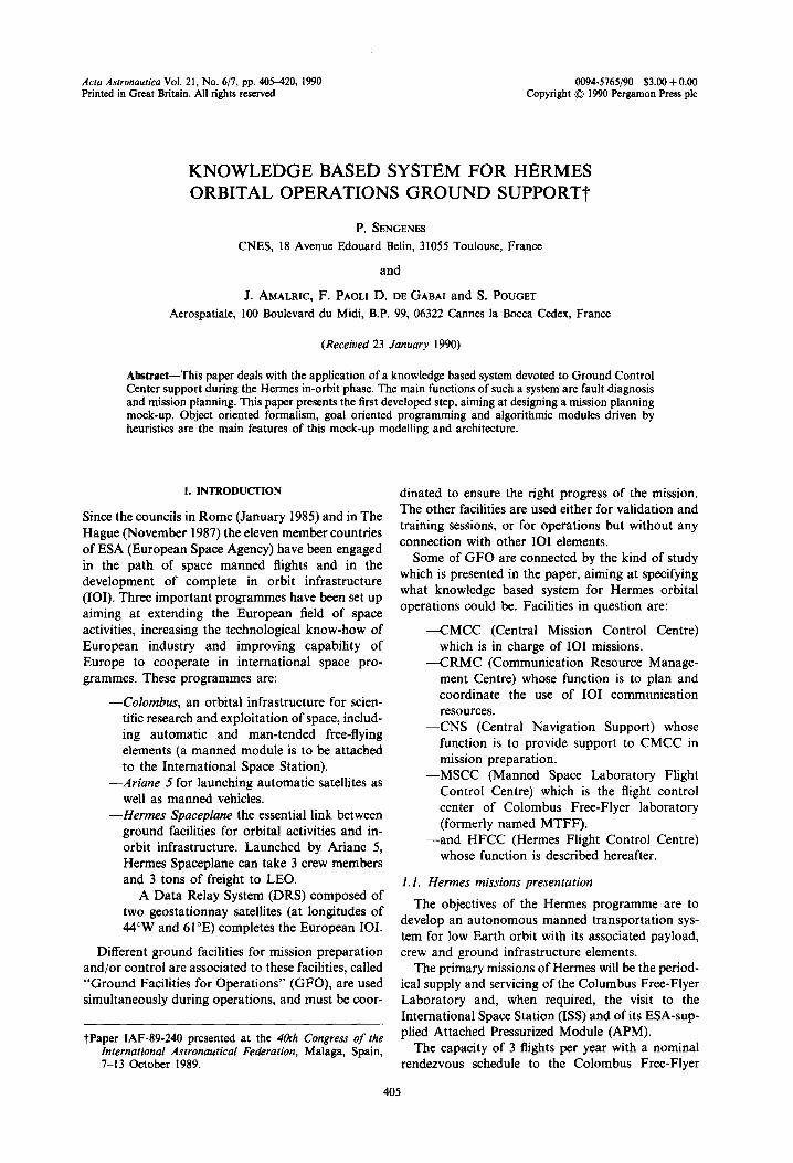
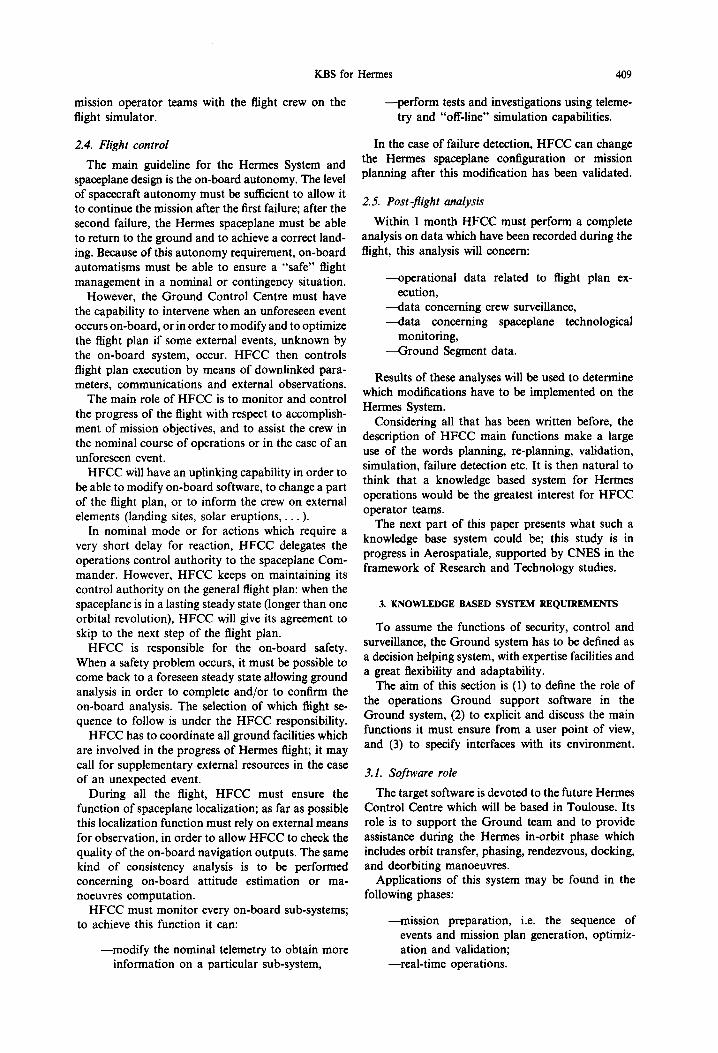
One of the main characteristics of Hermes is the capacity for reutilization, which requires complete vehicle refurbushing before each flight (Fig. 1).
I. I. 1. Description o f Hermes reference mission: ser- vicing o f the Colombus Free-Flyer Laboratory. The flight begins with the injection of Hermes by Ariane 5 into the Space Station orbital plane on a trajectory inclined at 28.5 ° to equatorial plane. Depending on the configuration which will be chosen for Her- mes/Ariane 5 composite vehicle, this injection may be achieved with a supplementary thrust provided by the MPH (Hermes Propulsion Module) and its two 27.5 kN engines.
The perigee of the post-injection trajectory is at an altitude of about 100 kin. The apogee altitude is a function of the Colombus Free-Flyer Laboratory altitude at the time of the flight--this altitude may change from 330 up to 483 km because of the require- ment for Colombus FFL orbit to be coplanar with the ISS orbit once every 180 days--and of the angular gap between Hermes and Colombus FFL at launch time. Because Space Station orbit plane acquisition determines a launch window of only a few seconds-- the required quantity of propellants would be pro- hibitive if acquisition were to be performed to orbit--the station may, a priori, be in any angular
position in its orbits and the resulting angular differ- ence must be caught up. This is the aim of "phasing".
Hermes follows an orbit of the semi-major axis which is shorter than that of the target station orbit and so has an angular velocity higher than that of the station (Kepler's 3rd law). The semi-major axis of this "phasing" orbit is adjusted according to the angular gap which is to be caught up by a thrust provided by the MRH (Hermes Resource Module) equipped with six 400 N engines when the spaceplane reaches the first apogee of the post-injection orbit. This allows Hermes to catch up the initial angular gap after a certain number of revolutions. The duration of this phase must not exceed 43 h.
At the end of phasing, Hermes is transferred from this "phasing" orbit to a quasi-circular orbit, 10 km below the Space Station.
"Homing" then begins, bringing Hermes into a stable waiting orbit with respect to the station, at a distance of 1 km. Different strategies can be im- plemented to achieve Homing like Hohmann transfer or "continuous thrusr'-type transfer.
After a waiting period spent at a distance of 1 km from the target station in order to get the right sun lighting conditions during docking, rendezvous ma- noeuvres start.
First Hermes is moved up to a distance of 100 m from the target by performing several radial impulses. At this point Hermes makes an U-turn to allow the CCD rendezvous cameras to acquire the docking axis. A final translation anchors the spaceplane to the Coiombus FFL.
Rendezvous is thus achieved less than 48 h after lift-off. In the framework of the main mission,
Launche sepa ra t
Deorbit
Take of 1
/ l , C r e w
Two-s tag adap t
l T PayLoad
Fig. 1. Hermes utilization cycle.
Runway
Hermes carrier a i r c ra f t
KBS for Hermes 407
Hermes can then remain docked to the station for 6 days. When this period has elapsed separation oper- ations are accomplished followed by a deorbiting manoeuvre, the timing of which is determined by the planned landing site.
The later manoeuvre causes Hermes to describe a ballistic arc bringing it back toward the Earth's surface. Spaceplane speed relative to the atmosphere is so great (~ 7 km/s) that it causes heating of the air close to Hermes. A plasma forms around the vehicle interrupting all radio links; this phenomenon is known as "black-out". It occurs during spaceplane re-entry at an altitude of between 80 and 50 km and lasts about 20 min.
The final flight phase consists of reaching the chosen landing site and executing several roll-rever- sals to align with the runway axis. It should be noted that the Hermes descent angle (about 18 ° ) is much higher than that of conventional aircrafts.
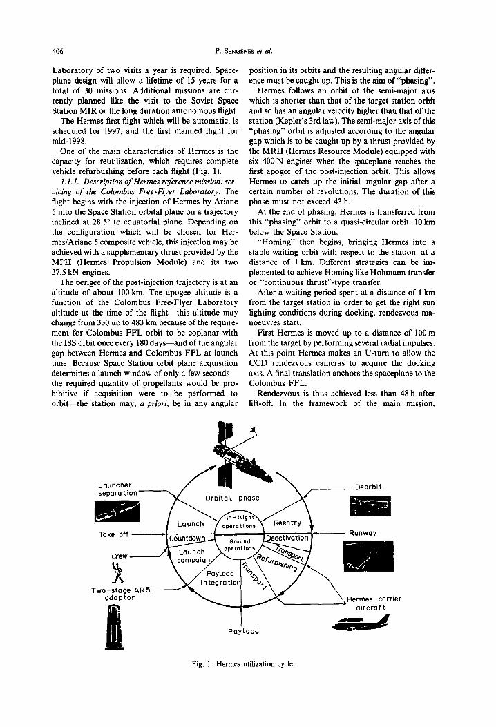
The progress of a typical Hermes mission is illus- trated in Fig. 2.
1.1.2. Hermes navigation and localization baseline description. To carry its mission through to a success- ful conclusion, Hermes has, on-board, several navi- gation equipment available to determine attitude, position and velocity of the spaceplane.
The attitude reference is provided to the spacecraft by three strap-down inertial measurement units put in skewed configuration in order to improve Hermes capability for failure self-detection.
The IMUs attitude estimation is periodically up- dated during orbital flight by CCD star trackers line-of-sight measurements in nominal mode or head- up display observations in degraded mode.
Position and velocity estimation mainly relies on IMUs during atmospheric phases (ascent and re-en- try) and on the orbital motion model during orbital
Deorb~ ~ mano~
flight. The trajectory estimation function is achieved by coupling the IMUs, or the orbital motion model, with the measurements (pseudo-ranges and pseudo- range rates) provided by two GPS receivers, every time these GPS measurements are available. In the case of GPS unavailability or receivers failure, the orbital motion model position and velocity predic- tions are updated by stellar refraction measurements or ground localization information.
During Homing and Docking phases, the GPS measurements obtained by the Space Station are transmitted to Hermes; these measurements are pro- cessed in connection with the Hermes GPS measure- ments in differential mode.
With regard to re-entry there is no real possibility of updating the inertial navigation during the "black- out" phenomenon.
The divergence of navigation error along vertical axis is limited by taking into account "pseudo-drag altitude" information.
From the end of the "black-out" to the touchdown on the landing site, the inertial navigation is updated by GPS measurements, or by the use of Trident IV radionavigation beacons if GPS is unavailable. Three radioaltimetres are provided on-board Hermes to allow the spaceplane to execute a correct flared-landing.
Different systems or facilities, like S-band or C- band ground stations, radar, or data relay satellites (DRS), participate in the ground localization function.
The localization function is carded out by the Hermes Flight Control Centre in order to:
- -make sure that the progress of Hermes mission is correct,
- -monitor on-board navigation function, and if some navigation equipment fails, update the on-board position and velocity state vector.
Entry
Fig. 2. Hermes flight profile.
408 P. SENOEr,r~ et al.
2. HERMES FLIGHT CONTROL CENTRE ROLE AND REQUIREMENTS
This localization function is not the only function that the HFCC must provide for a given mission, the role of HFCC consists of:
--assisting the CMCC in mission analysis and preparation,
----carrying out the flight control function: • providing on-board activities surveillance • checking the good working order of Hermes
spaceplane • assisting the crew in flight management in
nominal or degraded situations • ensuring on-board safety in all flight phases,
--performing post-flight analysis.
HFCC has also permanent functions to maintain like:
----coordinating all Hermes ground facilities, --managing Hermes system configurations, --providing ground operator teams training
sessions, --maintaining relations with mass media.
2.1. Mission analysis
During mission analysis, HFFC has to provide technical support to CMCC in order to define the mission plan, the overall mission preparation plan- ning including the end-to-end validation of the sys- tem, the particular mission requirements ("mission fitting" requirements).
HFCC is more particularly responsible for the following studies:
--mission feasibility studies considering Hermes spaceplane capabilities and constraints,
--mission feasibility studies regarding the dock- ing between Hermes and the target spacecraft,
--flight dynamics studies, --safety studies (crew safety, spaceplane safety,
payloads safety, Colombus FFL/Hermes and Ariane 5/Hermes composite vehicles safety).
HFCC must define the "mission fitting" require- ments concerning Hermes Ground Segment, Hermes spaceplane, and the System operating rules. It has no schedule Hermes spaceplane and Hermes Ground Segment preparation activities. It must provide a planning for the overall Hermes System validation, and determine which external resources are required by the Hermes System.
2.2. Mission preparation
During mission preparation, HFCC takes part in carrying out modifications in the Hermes System according to the "mission fitting" requirements, and validates them. Regarding the operations plan, HFCC is responsible for defining the Hermes space- plane flight plan, including the docked phase. It has to check the consistency of this flight plan with the
target station flight plan and the payloads experimen- tation programme.
Operations plans have to be worked out for nom- inal flight progress and for contingency situations. Safe spaceplane steady states and transitions for reaching these steady states must be defined as com- pletely as possible in order to make every kind of operations plan chaining feasible:
- -nominal plan, --foreseen plan for contingency situation when
the problem is identified, --operations plan which is defined and uplinked
by HFCC, in case of an unforeseen event, ---operations plan which is defined and applied
by the crew when communications between the spacecraft and HFCC are impossible.
This rule concerns free flight phases as well as the docked phase.
Operations plans regarding crew activities on pay- loads or on Colombus FFL, will be defined by the teams which are responsible for payloads or Colom- bus FFL. HFCC has to check the consistency of these activities with the general flight plan. "One-line" re-planning of these operations must be possible within the limits defined by the flight plan, and under HFCC control.
HFCC is responsible for defining all possible ac- tions regarding safety or emergency situations.
It must define operations plan for Hermes Ground segment, including cases of contingency situations; the definition of the use of the external resources which are required in the different flight phases (preparation, management, post-analysis) is the re- sponsibility of the HFCC.
HFCC is responsible for the definition and the validation of all Hermes Ground Segment pro- cedures, these procedures will be validated with the involvement of operator teams.
Mission parameters updating is carried out by the HFCC for all parameters regarding the Hermes System; it gets the supplementary information which are necessary to control the flight plan execution from CMCC concerning mission data, from MSCC con- cerning Colombus data, from CSG (Guyana Space Centre) concerning Ariane-5 data.
Last, during this phase of mission preparation, HFCC runs ground operator teams training sessions.
2.3. Flight preparation
The aim of this phase is to change from a "mis- sion" System configuration which has been analysed and "off-line" validated, to a configuration allowing operational flight control.
HFCC's work is to set and validate the flight plan chronology. If the launch time is delayed, HFCC must be able to quickly update the flight plan.
HFCC is responsible for the overall Hermes system validation, this validation is performed by the
KBS for Hermes 409
mission operator teams with the flight crew on the flight simulator.
--perform tests and investigations using teleme- try and "off-line" simulation capabilities.
2.4. Flight control
The main guideline for the Hermes System and spaceplane design is the on-board autonomy. The level of spacecraft autonomy must be sufficient to allow it to continue the mission after the first failure; after the second failure, the Hermes spaceplane must be able to return to the ground and to achieve a correct land- ing. Because of this autonomy requirement, on-board automatisms must be able to ensure a "safe" flight management in a nominal or contingency situation.
However, the Ground Control Centre must have the capability to intervene when an unforeseen event occurs on-board, or in order to modify and to optimize the flight plan if some external events, unknown by the on-board system, occur. HFCC then controls flight plan execution by means of downlinked para- meters, communications and external observations.
The main role of HFCC is to monitor and control the progress of the flight with respect to accomplish- ment of mission objectives, and to assist the crew in the nominal course of operations or in the case of an unforeseen event.
HFCC will have an uplinking capability in order to be able to modify on-board software, to change a part of the flight plan, or to inform the crew on external elements (landing sites, solar eruptions,. . . ).
In nominal mode or for actions which require a very short delay for reaction, HFCC delegates the operations control authority to the spaceplane Com- mander. However, HFCC keeps on maintaining its control authority on the general flight plan: when the spaceplane is in a lasting steady state (longer than one orbital revolution), HFCC will give its agreement to skip to the next step of the flight plan.
HFCC is responsible for the on-board safety. When a safety problem occurs, it must be possible to come back to a foreseen steady state allowing ground analysis in order to complete and/or to confirm the on-board analysis. The selection of which flight se- quence to follow is under the HFCC responsibility.
HFCC has to coordinate all ground facilities which are involved in the progress of Hermes flight; it may call for supplementary external resources in the case of an unexpected event.
During all the flight, HFCC must ensure the function of spaceplane localization; as far as possible this localization function must rely on external means for observation, in order to allow HFCC to check the quality of the on-board navigation outputs. The same kind of consistency analysis is to be performed concerning on-board attitude estimation or ma- noeuvres computation.
HFCC must monitor every on-board sub-systems; to achieve this function it can:
--modify the nominal telemetry to obtain more information on a particular sub-system,
In the case of failure detection, HFCC can change the Hermes spaceplane configuration or mission planning after this modification has been validated.
2.5. Post-flight analysis
Within 1 month HFCC must perform a complete analysis on data which have been recorded during the flight, this analysis will concern:
--operational data related to flight plan ex- ecution,
---data concerning crew surveillance, - -da ta concerning spaceplane technological
monitoring, ----Ground Segment data.
Results of these analyses will be used to determine which modifications have to be implemented on the Hermes System.
Considering all that has been written before, the description of HFCC main functions make a large use of the words planning, re-planning, validation, simulation, failure detection etc. It is then natural to think that a knowledge based system for Hermes operations would be the greatest interest for HFCC operator teams.
The next part of this paper presents what such a knowledge base system could be; this study is in progress in Aerospatiale, supported by CNES in the framework of Research and Technology studies.
3. KNOWLEDGE BASED SYSTEM REQUIREMENTS
To assume the functions of security, control and surveillance, the Ground system has to be defined as a decision helping system, with expertise facilities and a great flexibility and adaptability.
The aim of this section is (1) to define the role of the operations Ground support software in the Ground system, (2) to explicit and discuss the main functions it must ensure from a user point of view, and (3) to specify interfaces with its environment.
3.1. Software role
The target software is devoted to the future Hermes Control Centre which will be based in Toulouse. Its role is to support the Ground team and to provide assistance during the Hermes in-orbit phase which includes orbit transfer, phasing, rendezvous, docking, and deorbiting manoeuvres.
Applications of this system may be found in the following phases:
--mission preparation, i.e. the sequence of events and mission plan generation, optimiz- ation and validation;
--real-time operations.
410 P. SEr4GE~S et al.
The basic functions of this system are:
--fault diagnosis, based of the functional teleme- try flow;
--mission planning and validation, taking into account the actual system configuration and the applicable constraints.
Two classes of end users are distinguished:
-- the class of expert users, which include mission analysis and space dynamics engineers, and experts attached to a specific sub-system of the spaceplane;
-- the class of Ground team operators.
As the requirements differ for these two classes (in terms of protection and interactivity levels), two operating modes are necessary.
3.2. Software functions
Even if critical functions for spaceplane security are protected by autonomous on-board automatic systems, any on-board incident treatment is limited by available computing power. The control centre has to dispose of fine investigation facilities in order to diagnose an incident and determine, with respect to the spaceplane state, the necessary operations to reroute Hermes on a predefined flight plan corre- sponding to nominal or contingent mission.
Moreover, the Flight Control Centre should be able to intervene and modify the operations plan if an external event, which is unknown on-board, occurs.
Due to the real-time features associated with mis- sion context, an applicability verification function has
to be added to the two basic functions (diagnosis and planning/replanning), aimed at verifying a new gener- ated mission plan that is effectively applicable before transmitting it to the spaceplane. In case of an anomaly, several operations plans could be generated and validated by the software, then submitted to the Ground team responsibles for the final choice.
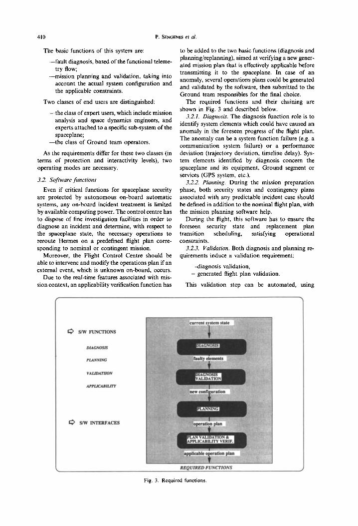
The required functions and their chaining are shown in Fig. 3 and described below.
3.2.1. Diagnosis. The diagnosis function role is to identify system elements which could have caused an anomaly in the foreseen progress of the flight plan. The anomaly can be a system function failure (e.g. a communication system failure) or a performance deviation (trajectory deviation, timeline delay). Sys- tem elements identified by diagnosis concern the spaceplane and its equipment, Ground segment or services (GPS system, etc.).
3.2.2. Planning. During the mission preparation phase, both security states and contingency plans associated with any predictable incident case should be defined in addition to the nominal flight plan, with the mission planning software help.
During the flight, this software has to ensure the foreseen security state and replacement plan transition scheduling, satisfying operational constraints.
3.2.3. Validation. Both diagnosis and planning re- quirements induce a validation requirement:
--diagnosis validation, --generated flight plan validation.
This validation step can be automated, using
I~ S/W FUNCTIONS
DIAGNOSIS
PLANNING
VALIDATIION
APPLICABILITY
S/W INTERFACES
REQUIRED FUNCTIONS
Fig. 3. Required functions.
KBS for Hermes 411
dynamic simulation techniques. Meanwhile, at last, human experts are in the loop.
Note that the simulator modelling has to be of the same decomposition level than the operations sup- port software one.
3.2.4. Applicability verification. Besides the real- time feature, the spatial system evolutive character has to be taken into account as an additive software function; an applicability verification function is necessary to ensure that a new mission plan, even if it is validated by simulation, is effectively applicable to the spaceplane.
During the diagnosis process, when a non nominal situation is detected, the system has to take into account that this situation might become critical, and then dangerous. During the planning process, the system has to foresee that it only has a short time to start a new planned operation. The system has also to take into account the human decision process duration.
3.3. Software interfaces
The Ground control operators interact with the knowledge based system with the aid of consoles which offer a visual representation of all the useful information. This display has to be Clear and familiar enough to the Ground team in order to make the mission real-time monitoring easier. For this purpose, both numerical and graphical displays can be used, with the help of menus and mousing techniques.
The user interface definition depends on the soft- ware function:
Interface with diagnosis function has to display the spaceplane sub-system and its equipment in which an anomaly has been detected.
Interface with planning function has at least to represent the mission plan and corresponding trajectory.
For both functions, the actual system configuration has to be displayed, with schematic representation of the current Ground segment, spatial segment and spaceplane configurations.
3.4. Mock-up requirements
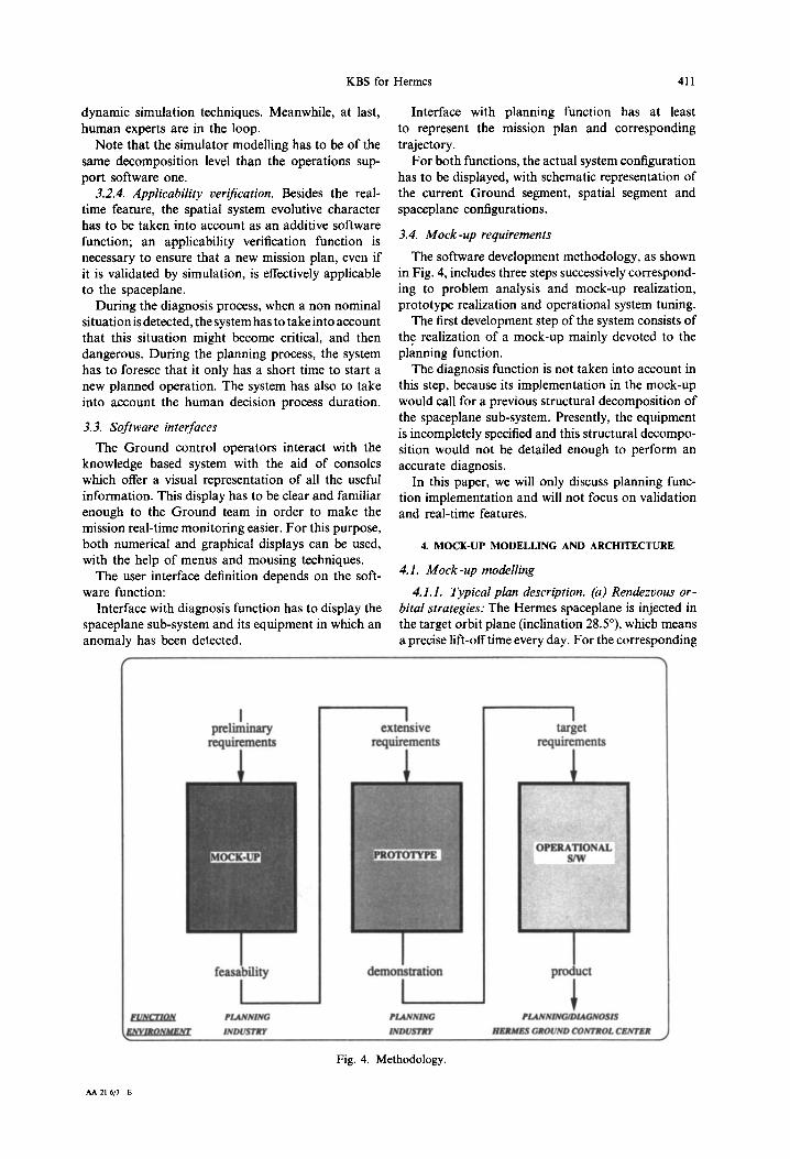
The software development methodology, as shown in Fig. 4, includes three steps successively correspond- ing to problem analysis and mock-up realization, prototype realization and operational system tuning.
The first development step of the system consists of the realization of a mock-up mainly devoted to the planning function.
The diagnosis function is not taken into account in this step, because its implementation in the mock-up would call for a previous structural decomposition of the spaceplane sub-system. Presently, the equipment is incompletely specified and this structural decompo- sition would not be detailed enough to perform an accurate diagnosis.
In this paper, we will only discuss planning func- tion implementation and will not focus on validation and real-time features.
4. MOCK-UP MODELLING AND ARCHITECTURE
4.1. Mock-up modelling
4.1.1. Typical plan description. (a) Rendezvous or- bital strategies: The Hermes spaceplane is injected in the target orbit plane (inclination 28.5°), which means a precise lift-offtime every day. For the corresponding
F U N C T I O N
E N V I R O N M E N T
I preliminary
requirements
I
feasability
I P L A N N I N G
I N D U S T R Y
I extensive
requirements
1 target
requirements
demonstration product
P L A N N I N G PLANNING~DIAGNOSIS
I N D U S T R Y H E R M E S GROUND CONTROL CENTER
Fig. 4. Methodology.
AA 21-6/7--E
412 P. S~NGE~.S e t a l .
Hermes phasing L.A.&S. strategy
22h 08mn__~.40.6 m/s • o o., . . . . . °o . .m , .
TronMer orbit N ",
N ~ Drift orbit "~,j/oLtitude : 200 km \'\)) Earth Target oR,rude 350kin
/1/
Injection orbit, /~. ~"
Oh 44ran -- .~"29,9 m/S
Hermes-M.T.F.E relative position
Fig. 5. Hermes phasing.
injection epoch, the difference between Hermes and the target has any value from 0 to 360 °. The target altitude is variable and ranges from about 330-483km. Hermes rendezvous strategies must then accommodate these phase and altitude ranges.
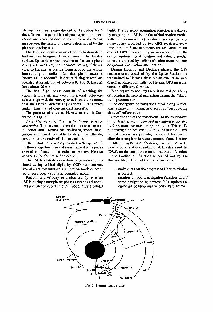
- - P h a s i n g s t r a t e g y (see Fig. 5 and [2]) The foreseen phasing strategy is as follows:
the Hermes propulsion module (MPH) injects the Hermes vehicle in an elliptic orbit with a 100kin perigee and an apogee altitude de- pending on the target phase and altitude. Then the propulsion module is jettisoned and the following manoeuvres are performed using the Hermes resource module (MRH).
The first manoeuvre occurs half an orbit after injection, i.e. at the apogee of the elliptic transfer orbit in order to make it circular. Hermes then stays a certain number of revolu- tions on this phasing orbit until the orbital periods difference between it and the target brings the phase angle to the desired value. Then the Hermes orbit altitude is raised to a few kilometre below the target altitude (typi- cally 10km), using a Hohman-type transfer (two impulses at half revolution intervals). At the end of the phasing, the spaceplane is about 10 km below and about 50 km behind the target.
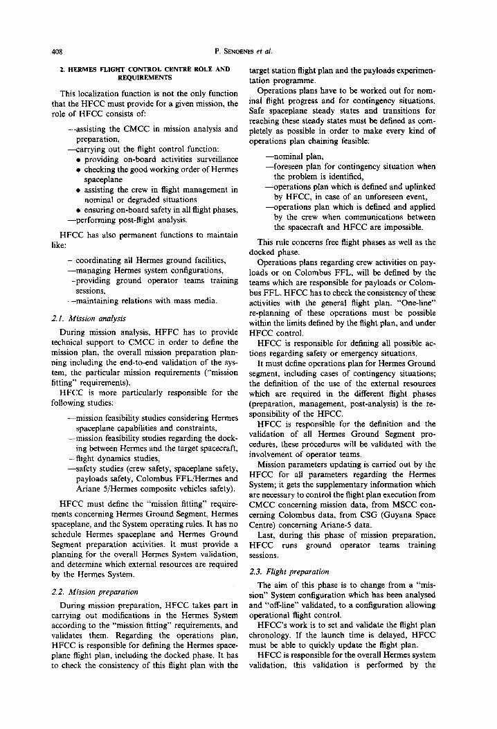
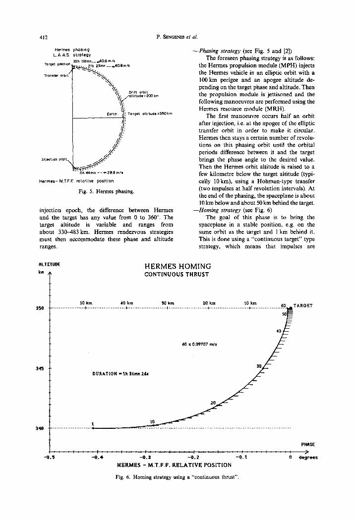
- - H o m i n g s t r a t e g y (see Fig. 6) The goal of this phase is to bring the
spaceplane in a stable position, e.g. on the same orbit as the target and 1 km behind it. This is done using a "continuous target" type strategy, which means that impulses are
I~LTI'I'UOE
ka
3'50
345
HERMES HOMING CONTINUOUS THRUST
: : : : : : : : : : : : : : : : : : : : : : : : : : : : : : : : : : : : : : : : : : : : : : : : : : : : -0 .5 - 0 . 4 -0 . S - 0 . 2 - 0 . 1 O
HERMES - M.T.F.F. R E L A T I V E POSITION
S0 km ,10 km 30 km Z0 kra 10 km . . . . . . . . . . . . . . . . . . . I. . . . . . . . . . . . . . . . . . . . . . , . . . . . . . . . . . . . . . . . . . . . . , . . . . . . . . . . . . . . . . . . . . . . }. . . . . . . . . . . . . . . . . . . . . . .I . . . . . . . . . . . . . . . . . . n .oy., T AKQ R T 'T'°-
80 x 0.09707 rnJs 40 S
/ - -
DUR&T[ON = th 3Lmn Zds 3 ~ / . _
PHASE /
degrees
Fig. 6. Homing strategy using a "continuous thrust".
KBS for Hermes 413
ALTrI'UD£
eletePs
200
100
-100
-200
-300
-400
-500
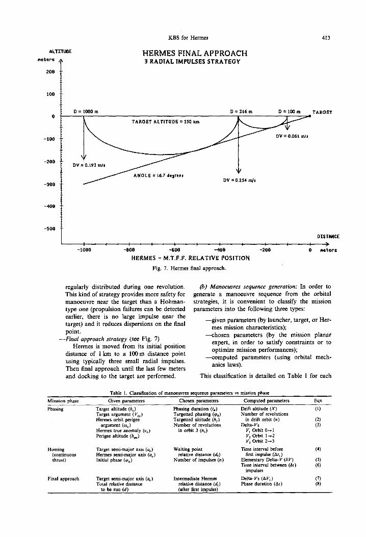
HERMES FINAL APPROACH RADIAL IMPULSES STRATEGY
D = I00Q m
DV = 0.L93 m J s ~
ANGLE =~ L6.7 delrees DV = 0254 m/s
D = 3 1 6 m D = 1 0 0 m
J I I J
- 1000 t ' I , I J I L I ~ I
-800 -600 -"40O
HERMES - M.T.F.F. R E L A T I V E POSITION
Fig. 7. Hermes final approach.
TAROST
o'rs'rliNCF
, I , i , I )
- 200 0 net.ePs
regularly distributed during one revolution. This kind of strategy provides more safety for manoeuvre near the target than a Hohman- type one (propulsion failures can be detected earlier, there is no large impulse near the target) and it reduces dispersions on the final point.
--Final approach strategy (see Fig. 7) Hermes is moved from its initial position
distance of I km to a 100 m distance point using typically three small radial impulses. Then final approach until the last few meters and docking to the target are performed.
(b) Manoeuvres sequence generation: In order to generate a manoeuvre sequence from the orbital strategies, it is convenient to classify the mission parameters into the following three types:
- -g iven parameters (by launcher, target, or Her- mes mission characteristics);
----chosen parameters (by the mission planar expert, in order to satisfy constraints or to optimize mission performances);
----computed parameters (using orbital mech- anics laws).
This classification is detailed on Table l for each
Table 1. Classification of manoeuvres sequence parameters vs mission phase Misssion phase Given parameters Chosen parameters Computed parameters Eqn
Phasing Target altitude (/I:) Phasing duration (t4) Drift altitude (X) (1) Target argument (V~o) Targetted phasing (¢4) Number of revolutions Hermes orbit perigee Targetted altitude (h3) in drift orbit (n) (2)
argument (too) Number of revolutions Delta- Vs (3) Hermes true anomaly (Vo) in orbit 3 (n 3) V] Orbit 0-,1 Perigee altitude (hvo) V2 Orbit I--,2
V 3 Orbit 2-,3
Homing Target semi-major axis (ac) Waiting point Time interval before (4) (continuous Hermes semi-major axis (ao) relative distance (dr) first impulse (Ah) thrust) Initial phase (t#o) Number of impulses (n) Elementary Delta-V (tV) (5)
Time interval between (60 (6) impulses
Final approach Target semi-major axis (a,) Intermediate Hermes Delta-Vs (AV~) (7) Total relative distance relative distance (at) Phase duration (At) (8)
to be run (d) (after first impulse)
414
LAUNCH a
P . SENGENES et al.
48 HOURS
l . . . . . . . . . • 1 : : : : : : : : : : : : : : : : : : : : : : : : : : : : : ] [ . . . . . . . . . ,
12H ISH30 18H 6 H 12H 13H30 18H
DOCKING 1 LAST LIMIT
L..~...-| ]
6H 7H30 12'H
K%\~\\NN1
I I
POSSIBLE PHASING MANOEUVRES PERIODS
FORBIDDEN PHASING MANOEUVRES PERIODS ICREW REST/SLEEP)
HOMING + DOCKING PERIOD
Fig. 8. Manoeuvres schedule vs crew time.
mission phase, giving reference to the equations detailed in the Appendix.
(c) Manoeuvre schedule constraints: Two important schedule constraints must be taken into account for the Hermes rendezvous strategies:
- -The mission duration limit leads to a maxi- mum of 48 h for rendezvous, including dock- ing to the MTFF.
- -The manoeuvres must be performed during crew activity periods: crew in flight time-table is shared between activity periods, from 6 a.m. to 6 p.m. in crew time, and rest (rest and sleep periods from 6 p.m. to 6 a.m,). Knowing the homing and docking phases durations (a total of 4.5h is typically taken) phasing ma- noeuvres must then be scheduled between 1.30
p.m. and 6 p.m. crew time. As launch will nominally correspond to 12 a.m. in crew time, the resulting periods for phasing manoeuvres are illustrated in Fig. 8.
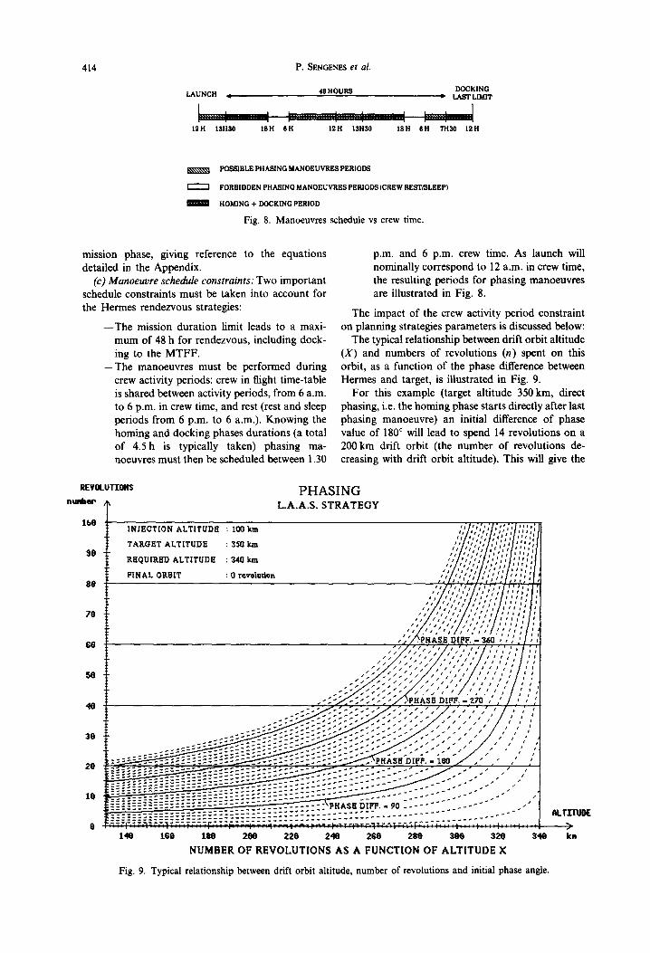
The impact of the crew activity period constraint on planning strategies parameters is discussed below:
The typical relationship between drift orbit altitude (X) and numbers of revolutions (n) spent on this orbit, as a function of the phase difference between Hermes and target, is illustrated in Fig. 9.
For this example (target altitude 350 kin, direct phasing, i.e. the homing phase starts directly after last phasing manoeuvre) an initial difference of phase value of 180 ° will lead to spend 14 revolutions on a 200 km drift orbit (the number of revolutions de- creasing with drift orbit altitude). This will give the
REVOLU~'ONS nu~er,
lbOg8 i"
PHASING L.A.A,S. STRATEGY
I N J E C T I O N A L T I T U D E : 100 km
TAKOET ALTITUDE : 350 k m
REQUIRED A L T I T U D E : 340 km
FINAL ORBIT : Q revoludan
70
$0 I~ DIFF. - 360 , ,
5O
40
30
20
16
0
" . ,~eHASE D[FF. - Z~
140 lSe t~0 2e0 22e 2,1e 26e 2$e 3co ~2o 3,1o NUMBER OF REVOLUTIONS AS A FUNCTION OF ALTITUDE X
Fig. 9. Typical relationship between drift orbit altitude, number of revolutions and initial phase angle.
~LTEfll0E
kn
KBS for Hermes 415
0
7 2
6 0
4 8
3 6
2 4
12
- - / l l / I l i t / I i I / l l t I l l I I Znjeotion attitude : /00k in / / I / l l / l l l l l / l l l l l l l I I
l / l / l / / I l l , i I I , 1 1 , I I ,a T a r g e t a t t i t u d e : 3 5 0 km
- - Required a t t i t u d e : 3 4 0 km
F i n a l o r b i t : 0 revo lu t ion
• / J s I P ¢ / / I I I / / I I I I I I I t I I / I / I / / 1 1 / i / I l l " " . ...;/.-?..:;/..;-...:./,, ,//,,/,,//
/.. ;~.-.'."~" -'." .'. I .... ,' I , i , ' Phase diff. compensed 360 330 300 :>70 240 210 180
L 345 315 285 255 225 195 150 120 90
t__ 165 135 105 75 45
. . . . . s_o_ _ . . . . . .-- J - " . . . . _.30 _ _ _ - - ' i s
[ - - ~ - - - = ? - - - - ~ - - - r - - - - - ~ : - - - r - - q - - - -J- , , 140 160 180 200 220 240 260 280 300 320
I 340
Att i tude (kml
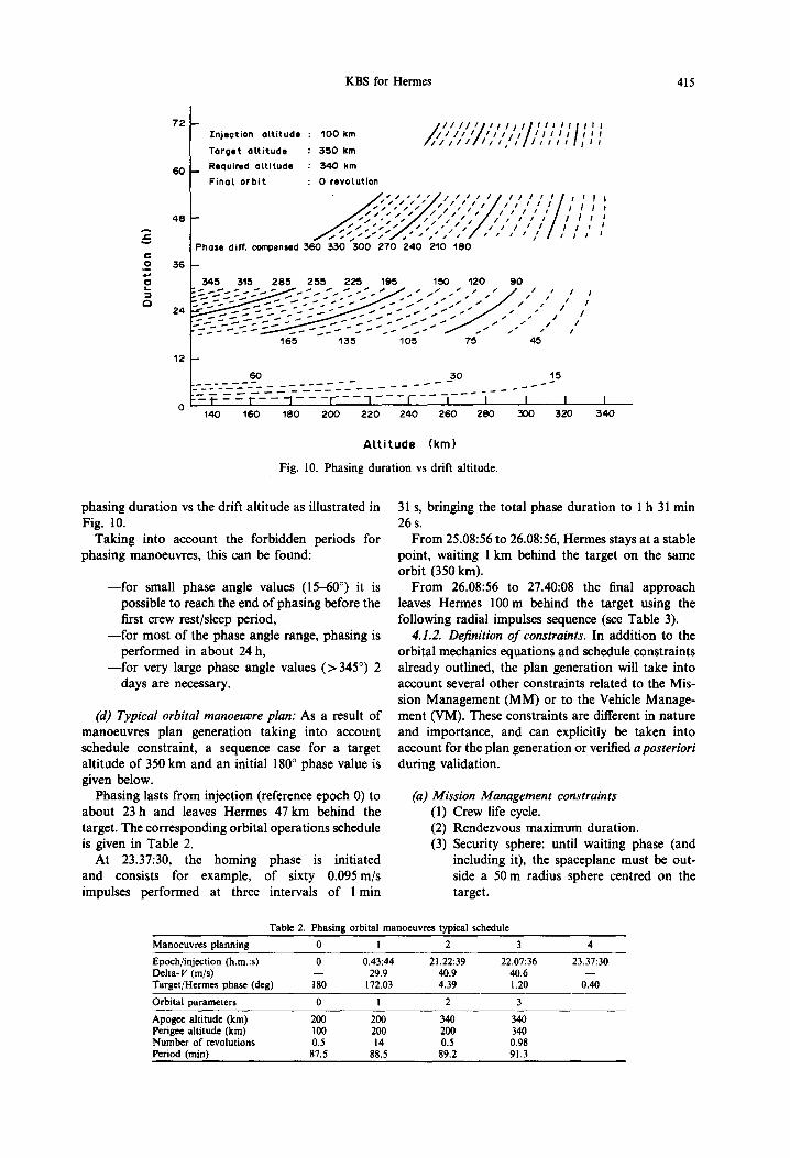
Fig. 10. Phasing duration vs drift altitude.
phasing duration vs the drift altitude as illustrated in Fig. 10.
Taking into account the forbidden periods for phasing manoeuvres, this can be found:
- - for small phase angle values (15-60 ° ) it is possible to reach the end of phasing before the first crew rest/sleep period,
- - for most of the phase angle range, phasing is performed in about 24 h,
- - for very large phase angle values (>345 °) 2 days are necessary.
(d) Typical orbital manoeuvre plan: As a result of manoeuvres plan generation taking into account schedule constraint, a sequence case for a target altitude of 350 km and an initial 180 ° phase value is given below.
Phasing lasts from injection (reference epoch 0) to about 23 h and leaves Hermes 47 km behind the target. The corresponding orbital operations schedule is given in Table 2.
At 23.37:30, the homing phase is initiated and consists for example, of sixty 0.095m/s impulses performed at three intervals of 1 min
31 s, bringing the total phase duration to 1 h 31 min 26 s.
From 25.08:56 to 26.08:56, Hermes stays at a stable point, waiting 1 km behind the target on the same orbit (350 km).
From 26.08:56 to 27.40:08 the final approach leaves Hermes 100m behind the target using the following radial impulses sequence (see Table 3).
4.1.2. Definition o f constraints. In addition to the orbital mechanics equations and schedule constraints already outlined, the plan generation will take into account several other constraints related to the Mis- sion Management (MM) or to the Vehicle Manage- ment (VM). These constraints are different in nature and importance, and can explicitly be taken into account for the plan generation or verified a posterior/
during validation.
(a) Miss ion Managemen t constraints
(1) Crew life cycle. (2) Rendezvous maximum duration. (3) Security sphere: until waiting phase (and
including it), the spaceplane must be out- side a 50 m radius sphere centred on the target.
Table 2. Phasing orbital manoeuvres typical schedule Manoeuvres planning 0 I 2 3 4 Epoch/injection (h.m.:s) 0 0.43:44 21.22:39 22.07:36 23.37:30 Delta- V (m/s) -- 29.9 40.9 40.6 -- Target/Hermes phase (de8) 180 172.03 4.39 1.20 0.40 Orbital parameters 0 1 2 3 Apogee altitude (km) 200 200 340 340 Perigee altitude (km) 100 200 200 340 Number of revolutions 0.5 14 0.5 0.98 Period (min) 87.5 88.5 89.2 91.3
416 P. SENGENES et al.
Table 3. Final approach orbital manoeuvres typical schedule Manoeuvres planning 1 2 3
Epoch/injection (h.m:s) 26.08:56 26.54:42 27.40:28 Delta- V (m/s) 0.194 0.257 0.063 Orbit eccentricity 2.53 x 10 5 8.17 × 10 -6 0
after manoeuvre
Co) Vehicle Management constraints (1) IMU modes switching: during phasing, it is
necessary to wait 30min before each manoeuvre for stabilization reasons, after switching from orbital mode 1 to orbital mode 2.
(2) IMU calibration: accelero calibration will require a certain time before the first homing manoeuvre.
(3) SST calibration after launch. (4) SST Sun dazzling: the Sun be out of the
sensor field of view (typically 20 ° ) during star sighting (phasing, homing, waiting phases).
(5) GPS visibility: measures require four satellites in the receiver antenna field (typically 80 ° around the Z-axis) during phasing, homing, waiting phases.#
(6) Differential GPS visibility: the four GPS satellites must be visible by both Hermes and M T F F and, in addition, a link between the two spacecraft must be established.
(7) GPS convergence time: filtering techniques need a convergence time to be taken into account after a manoeuvre is performed or the measurement stream is interrupted.
(8) SRV maximum distance (about 100 m from target) and field of view (typically 5 ° around the X-axis).
(9) SRV Sun dazzling: a forbidden cone around the sensor axis will be taken into account.
(10) Sunlight conditions for docking: the Sun must light the target and, more precisely, the docking port in order to provide good conditions for crew for direct or camera-as- sisted visions of the target.
4.1.3. Planning work modelling. Before any planning activity description, the used terminology has to be introduced in order to make the planning work modelling easier.
A state is defined by current trajectory and both spaceplane equipments and services configurations.
A goal is the final state expected to be reached. A strategy is globally characterized by its number
of impulses, their amplitude and date, and their direction. Besides, according to the strategy flight phase, some specific parameters may be used to define
tThe applicability of constraints (5) and (6) depend on the kind of GPS measurements processing which is im- plemented in the Hermes navigation software.
a strategy (e.g. phase angle is used to characterize any phasing strategy).
A scenario is a class of strategy, i.e. only a part of the strategy parameters have an assigned value.
A plan is a succession of strategies. A sequence is a sucession of scenarii. In other
words, a sequence is a class of plan. In the frame of the considered reference mission,
four high level goals are foreseen, each of them being defined by a peculiar state: rendezvous, Earth return, mission abortion and emergency return.
For a given high level goal, planning activity mainly includes two steps in order to:
Step I:
Step 2:
Define intermediate goals and scenarii allowing to reach them, taking into ac- count the initial state and MM con- straints. Then a sequence is issued from this step. For each scenario, define intermediate goals, if necessary, and compute the impulses allowing to reach them, taking into account the initial state and VM constraints. Then a plan is issued from this step.
In Step 1 time is taken into account in a relative way (i.e. reference time is crew time), whereas in Step 2 it is taken into account in an absolute way (i.e. reference time is UTC time). As a matter of fact, on the one hand MM constraints call for duration in crew time (e.g. no manoeuvre during crew sleep and rest period) and on the other hand, VM contraints call for finer datation in UTC time (e.g. Sun position computation).
At each step, three sets of parameters are available: given parameters, chosen parameters and computed parameters.
The given parameters express the goal to reach and the initial state, the chosen and computed parameters express the intermediate goals and the associated scenarii.
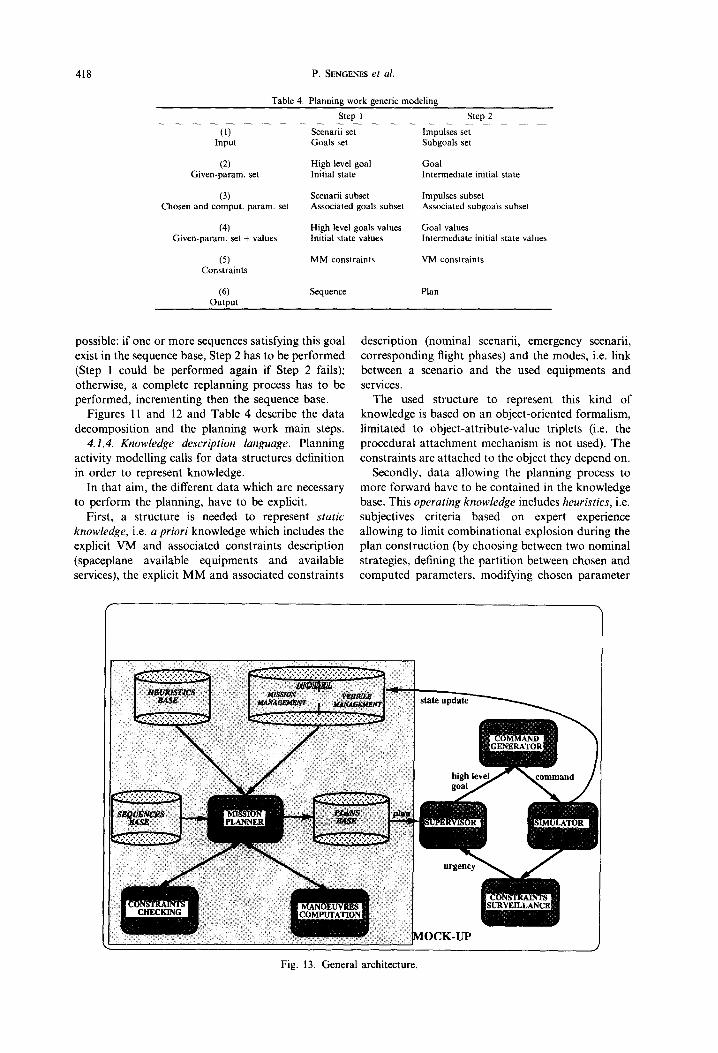
The complexity of planning activity mainly consists of the definition of chosen and computed parameters sets, and in chosen parameters valuation. As a matter of fact, each step includes constraints checking: a sequence is issued from the first step if every MM constraint is satisfied; in the same way, a plan is issued from the second step if every VM constraint is satisfied. If one of the current constraints is not satisfied, the it is necessary to successively reconsider the values assessed to chosen parameters, the partition between chosen and computed parameters, and the current goal.
These kinds of definitions and valuations are based on subjective criteria used by human experts, and not on pure algorithmic valuation. Therefore, planning work modelling calls for a knowledge based system approach, since it is the only way to simulate a human expert subjective reasoning.
KBS for Hermes 417
I STEP 2 STEP 1
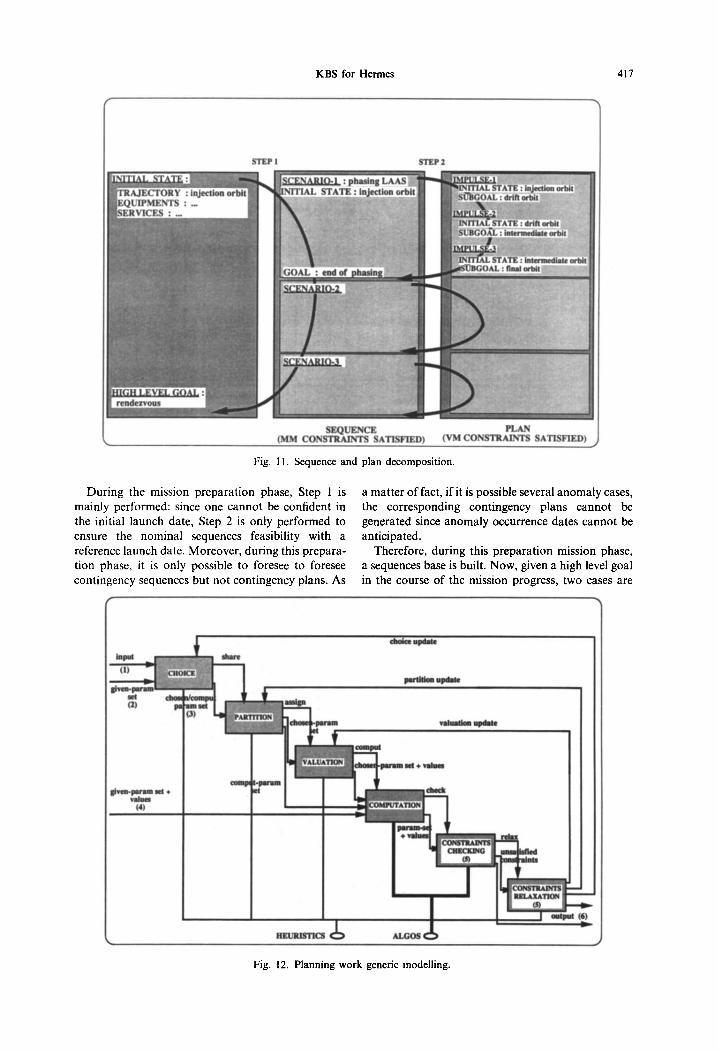
Fig. 11. Sequence and plan decomposition.
During the mission preparation phase, Step 1 is mainly performed: since one cannot be confident in the initial launch date, Step 2 is only performed to ensure the nominal sequences feasibility with a reference launch date. Moreover, during this prepara- tion phase, it is only possible to foresee to foresee contingency sequences but not contingency plans. As
a matter of fact, if it is possible several anomaly cases, the corresponding contingency plans cannot be generated since anomaly occurrence dates cannot be anticipated.
Therefore, during this preparation mission phase, a sequences base is built. Now, given a high level goal in the course of the mission progress, two cases are
choice update
set ° s ~ set u [ ~ nsstgn ch camp (2) m
partition update
valuation update
comput
given-param set + values
(4)
check
HEURISTICS C ~ ALGOS (
Fig. 12. Planning work generic modelling.
output (6)
418 P. SENGENES et al.
Table 4. Planning work generic modeling Step 1 Step 2
(1) Scenarii set Impulses set Input Goals set Subgoals set
(2) High level goal Goal Given-param. set Initial state Intermediate initial state
(3) Scenarii subset Impulses subset Chosen and comput, param, set Associated goals subset Associated subgoals subset
(4) High level goals values Goal values Given-param. set + values Initial state va lues Intermediate initial state values
(5) MM constraints VM constraints Constraints
(6) Sequence Plan Output
possible: if one or more sequences satisfying this goal exist in the sequence base, Step 2 has to be performed (Step 1 could be performed again if Step 2 fails); otherwise, a complete replanning process has to be performed, incrementing then the sequence base.
Figures 11 and 12 and Table 4 describe the data decomposition and the planning work main steps.
4.1.4. Knowledge description language. Planning activity modelling calls for data structures definition in order to represent knowledge.
In that aim, the different data which are necessary to perform the planning, have to be explicit.
First, a structure is needed to represent static knowledge, i.e. a priori knowledge which includes the explicit VM and associated constraints description (spaceplane available equipments and available services), the explicit MM and associated constraints
description (nominal scenarii, emergency scenarii, corresponding flight phases) and the modes, i.e. link between a scenario and the used equipments and services.
The used structure to represent this kind of knowledge is based on an object-oriented formalism, limitated to object-attribute-value triplets (i.e. the procedural attachment mechanism is not used). The constraints are attached to the object they depend on.
Secondly, data allowing the planning process to more forward have to be contained in the knowledge base. This operating knowledge includes heuristics, i.e. subjectives criteria based on expert experience allowing to limit combinational explosion during the plan construction (by choosing between two nominal strategies, defining the partit ion between chosen and computed parameters, modifying chosen parameter
Fig. 13. General architecture.
KBS for Hermes 419
values, deciding of a new goal, etc.). Furthermore, the operating knowledge also needs structures for se- quences andplans explicit description, sequences being both input and output data of the planning process.
The chosen structure used to express the operating knowledge is the "Knowledge Area" (KA) (see [1]). Each KA is composed of two parts: an invocation condition, which describes the activation context for a given goal, and a body, organized in a recursive transitive network, describing information on the operations to be performed in order to reach the goal.
Such a structure is suitable to describe sequences or plans, since it allows to express both goal oriented reasoning and the procedural feature of this kind of knowledge. However, even if production rule formal- ism (whose typical syntax is " IF conditions THEN actions") is generally used to express heuristics, the KA structure allows to make multiple conditions into account.
Lastly, an algorithmic knowledge component is needed in the knowledge base, which includes all the
necessary algorithm libraries for constraint valuation of manoeuvre computation. These algorithmic modules are classically written in an imperative language such as C or Pascal.
4.2. Mock-up architecture
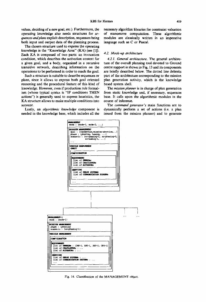
4.2.1. General architecture. The general architec- ture of the overall planning tool devoted to Ground centre support is shown in Fig. 13 and its components are briefly described below. The dotted line delimits part of the architecture corresponding to the mission plan generation activity, which is the knowledge based system shell.
The mission planner is in charge of plan generation from static knowledge and, if necessary, sequences base. It calls upon the algorithmic modules in the course of inference.
The command generator's main functions are to dynamically perform a set of actions (i.e. a plan issued from the mission planner) and to generate
( rendezvous, missiom-abor ti ..... ~I
2,
i ~ ~ ~ m o d e : (~I, m~-2, ...} I ~ : (pluas~_,~, hom~ ~., . I s c o r a t x i o : (sc~i~. ] , S,
paase : (phasing, hua~g .... ) scenario : {sc-p~asing-l, sc-~hasing~2
se-haming-1 .... )
~ ing-i }
list of ~ : (3~a-J-l, SST-I, SST-2, f~S-1) list of C~T/"Or_ aK~Rs : ... last of ~ : ...
list of R~%YSY~IZ~ : ... llst of C~M~II~KTIE~ : ...
I I . . . . . .
Fig. 14. Classification of the MANAGEMENT object.
420 P, SENGENKS et al.
commands in order to reach a final state from an initial state.
The constraints surveil lance module permanently looks after general constraints, whether they are temporal or factual, and sends a message to the supervisor in case of an emergency situation.
The s imula tor simulates the Hermes spaceplane flight evolution, from Ground commands generated by the command generator.
4.2.2. Knowledge base description. In this paper, only the knowledge base static component is presented, the operating component being currently under development.
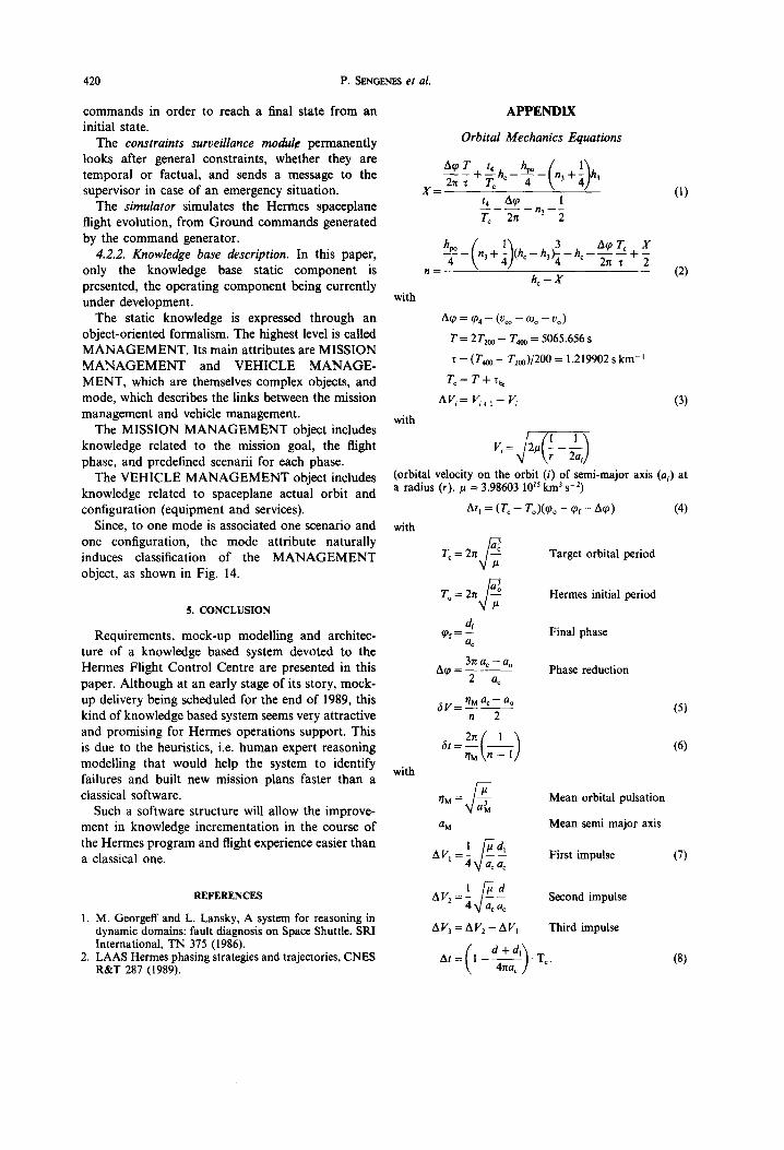
The static knowledge is expressed through an object-oriented formalism. The highest level is called M A N A G E M E N T . Its main attributes are MISSION M A N A G E M E N T and VEHICLE M A N A G E - MENT, which are themselves complex objects, and mode, which describes the links between the mission management and vehicle management.
The MISSION M A N A G E M E N T object includes knowledge related to the mission goal, the flight phase, and predefined scenarii for each phase.
The VEHICLE M A N A G E M E N T object includes knowledge related to spaceplane actual orbit and configuration (equipment and services).
Since, to one mode is associated one scenario and one configuration, the mode attribute naturally induces classification of the M A N A G E M E N T object, as shown in Fig. 14.
5. CONCLUSION
Requirements, mock-up modelling and architec- ture of a knowledge based system devoted to the Hermes Flight Control Centre are presented in this paper. Although at an early stage of its story, mock- up delivery being scheduled for the end of 1989, this kind of knowledge based system seems very attractive and promising for Hermes operations support. This is due to the heuristics, i.e. human expert reasoning modelling that would help the system to identify failures and built new mission plans faster than a classical software.
Such a software structure will allow the improve- ment in knowledge incrementation in the course of the Hermes program and flight experience easier than a classical one.
REFERENCES
1. M. Georgeff and L. Lansky, A system for reasoning in dynamic domains: fault diagnosis on Space Shuttle. SRI International, TN 375 (1986).
2. LAAS Hermes phasing strategies and trajectories, CNES R&T 287 (1989).
with
with
A P P E N D I X
Orbi ta l Mechan ic s Equat ions
Acp T t 4 hpo / 1 \
X = f4 A~ 1 T~ 2n n3 2
n
h c - ~"
(i)
(2)
A~o = ~o 4 - (Voo - COo - Vo)
T = 2T2o o - T4oo = 5065.656 s
x = (T4oo - T2oo)/200 = 1.219902 s km -I
T¢= T +'f h~
a v , = v~ + ~ - v , (3)
(orbital velocity on the orbit (i) of semi-major axis (a~) at a radius (r). # = 3.98603 1015 km 3 s -z)
At I = (T¢ - To)(~o o - ~pf- atp) (4)
with
T~ = 2 n ; ~ Target orbital period
T o = 2n Hermes initial period
4 q~f = - Final phase ac
3n ac - ao A~0 Phase reduction
2 a¢
~V= T/M ac - a° (5) n 2
rlM kn - 1] (6)
with
~M = Mean orbital pulsation
a M Mean semi major axis
1 /# ~ First impulse (7) AV, =4V a~ac
iJd A V 2 = ~ k]~¢ ; Second impulse
AV3 = AV2 - AVI Third impulse
( T At= 1- - -4~a¢] ' ~" (8)