Embed Size (px)
Citation preview
KODAK 8000 and KODAK 8000C Extraoral Imaging Systems
Safety, Regulatory & Technical Specification User Guide
Notice
The Regulatory Information & Technical Specifications User Guide for the KODAK 8000 and KODAK 8000C Extraoral Imaging Systems includes information on the safety instructions, regulatory information and the technical specifications of the devices. We recommend that you thoroughly familiarize yourself with this Guide in order to make the most effective use of your system.
The information contained in this Guide may be subject to modification without notice, justification or notification to the persons concerned.
No part of this Guide may be reproduced without the express permission of Carestream Health, Inc.
U.S. Federal law restricts this device to sale by or on the order of a dentist or physician.
This document is originally written in English.
Manual Name: KODAK 8000 and KODAK 8000C Extraoral Imaging Systems Safety, Regulatory and Technical Specifications User GuidePart Number: SM743Revision Number: 01Print Date: 03/2010
The Brand names and logos reproduced in this Guide are copyrightKODAK is a trademark of KODAK used under Licence.KODAK 8000 and KODAK 8000C Extraoral Imaging Systems, comply with Directive 93/42/CEE relating to medical equipment.
Manufacturer
Authorized Representative in the European Community
TROPHY 4, Rue F. Pelloutier, Croissy-Beaubourg
77435 Marne la Vallée Cedex 2, France
0086
Carestream Health, Inc.150 Verona StreetRochester NY 14 608
EC REP
KODAK 8000 and 8000C System_Safety, Regulatory & Technical Specifications (SM743)_Ed01 iii
Contents
Chapter 1Safety Information
Indications for Use . . . . . . . . . . . . . . . . . . . . . . . 1
Conventions in this Guide . . . . . . . . . . . . . . . . . . . 1
Note to the User . . . . . . . . . . . . . . . . . . . . . . . . 2
Warning and Safety Instructions . . . . . . . . . . . . . . . . 2
Warning and Safety Instructions . . . . . . . . . . . . . . . . 3
Hygiene and Disinfection . . . . . . . . . . . . . . . . . . . . 4
Marking and Labeling Symbols. . . . . . . . . . . . . . . . . 5
Label Locations . . . . . . . . . . . . . . . . . . . . . . . . . 6
KODAK 8000 Labels . . . . . . . . . . . . . . . . . . . 6
KODAK 8000C Labels . . . . . . . . . . . . . . . . . . 7
Chapter 2Regulatory Information
General Regulatory Information . . . . . . . . . . . . . . . . 9
Compliance with International Regulations . . . . . . . . . 14
Chapter 3Technical Specifications
Factory . . . . . . . . . . . . . . . . . . . . . . . . . . . . 15
Manufacturer . . . . . . . . . . . . . . . . . . . . . . . . . 15
Model . . . . . . . . . . . . . . . . . . . . . . . . . . . . . 15
KODAK 8000 and KODAK 8000C Systems Technical
Specifications. . . . . . . . . . . . . . . . . . . . . . . . . 15
KODAK 8000 and KODAK 8000C Systems Environmental
Requirements . . . . . . . . . . . . . . . . . . . . . . . . . 16
KODAK 8000 and KODAK 8000C Systems Electrical
Specifications. . . . . . . . . . . . . . . . . . . . . . . . . 17
X-Ray Tube Assembly Technical Specifications . . . . . . . 18

iv
KODAK 8000 and 8000C System_Safety, Regulatory & Technical Specifications (SM743)_Ed01 1
1 Safety Information
Indications for UseThe KODAK 8000 and KODAK 8000C Extraoral Imaging Systems are intended to be used at the direction health care professionals for dental volumetric reconstruction of extra-oral dento- maxillo-facial region of the human anatomy.
Conventions in this GuideThe following special messages emphasize information or indicate potential risk to personnel or equipment:
WARNING: Warns you to avoid injury to yourself or others by following the safety instructions precisely.
CAUTION: Alerts you to a condition that might cause serious damage.
Important: Alerts you to a condition that might cause problems.
Note: Emphasizes important information.
Tip: Provides extra information and hints.
2 Chapter 1 Safety Information
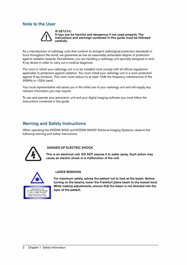
Note to the User
WARNINGX-rays can be harmful and dangerous if not used properly. The instructions and warnings contained in this guide must be followed carefully.
As a manufacturer of radiology units that conform to stringent radiological protection standards in force throughout the world, we guarantee as low as reasonably achievable degree of protection against radiation hazards. Nonetheless, you are handling a radiology unit specially designed to emit X-ray doses in order to carry out a medical diagnosis.
The room in which your radiology unit is to be installed must comply with all official regulations applicable to protection against radiation. You must install your radiology unit in a room protected against X-ray emission. This room must reduce to at least 12db the frequency interferences of the 30MHz to 1GHz band.
Your local representative will assist you in the initial use of your radiology unit and will supply any relevant information you may require.
To use and operate your panoramic unit and your digital imaging software you must follow the instructions contained in this guide.
Warning and Safety InstructionsWhen operating the KODAK 8000 and KODAK 8000C Extraoral Imaging Systems, observe the following warning and safety instructions:
DANGER OF ELECTRIC SHOCK
This is an electrical unit. DO NOT expose it to water spray. Such action may cause an electric shock or a malfunction of the unit.
LASER WARNING
For maximum safety, advise the patient not to look at the beam. Before turning on the beams, lower the Frankfurt plane beam to the lowest level. While making adjustments, ensure that the beam is not directed into the eyes of the patient.
KODAK 8000 and 8000C System_Safety, Regulatory & Technical Specifications (SM743)_Ed01 3
Warning and Safety InstructionsWARNINGS
Unit:
• Read and understand this Safety Information before using the KODAK 8000 and KODAK 8000C Extraoral Imaging Systems.
• You are responsible for the operation and maintenance of this unit. Only legally qualified persons can operate this unit. They MUST have training to use the radiological equipment. DO NOT open the cover of the unit. When necessary, have a trained authorized service technician carry out inspection and maintenance operations.
• Install this unit in an X-ray room that complies with current installation standards. From this location, you must be able to maintain visual or audio communication with the patient and be able to access the Acquisition interface module during exposure.
• This unit must be permanently connected to the ground with a fixed power supply cable. To avoid the risk of electric shock, this equipment must ONLY be connected to a mains supply with protective earth.
• DO NOT operate the unit if there is the threat of an earthquake. Following an earthquake, ensure that the unit is operating satisfactorily before using it again. Failure to observe this precaution may expose patients to hazards.
• X-ray equipment is hazardous to patients and the operator if you do not observe the exposure safety factors and operating instructions.
• DO NOT place objects within the field of operation of the unit.• The patient should wear a protective lead-lined shoulder apron, unless other Radiation
Protection Protocols apply locally.• While adjusting the height of the unit, ensure that the patient is kept clear of the
mechanism.• When the unit is not in use, ensure that the ON/OFF switch is set to OFF (O).• If the unit develops a fault, switch it to off (O), display an “Unserviceable” notice and
contact a service technician.• To dispose of the unit or its components, contact a service technician.• Ask the patient to refrain from moving during the entire period of exposure. • Ask the patient to remain still until the unit arm has stopped moving and the RESET
movement has completed.• DO NOT use this unit in conjunction with oxygen-rich environments. This unit is not
intended for use with flammable anesthetics or flammable agents.• DO NOT hang from the cephalostat.• Using accessories other than those specified in this document with the exception of
those sold by Carestream Health may result in a lower level of security for the entire system.
Computer:
• DO NOT place the computer and the peripheral equipment connected to it in the immediate vicinity of the patient in the unit. Leave at least 1.5 m distance between the patient and the unit. The computer and the peripheral equipment must conform to the IEC60950 standard.
• See your computer installation guide for details of the data processing system and screen. Leave a sufficient amount of clear space around the CPU to ensure that it is properly ventilated.
• To obtain maximum image quality and visual comfort, position the screen to avoid direct light reflections from internal or external lighting.
4 Chapter 1 Safety Information
Hygiene and DisinfectionWARNINGS
• Disinfect any parts of the unit that come into contact with the patient and the operator after each patient has been exposed to X-rays.
• To prevent cross-contamination, use a new hygienic sleeves for each new patient.
KODAK 8000 and 8000C System_Safety, Regulatory & Technical Specifications (SM743)_Ed01 5
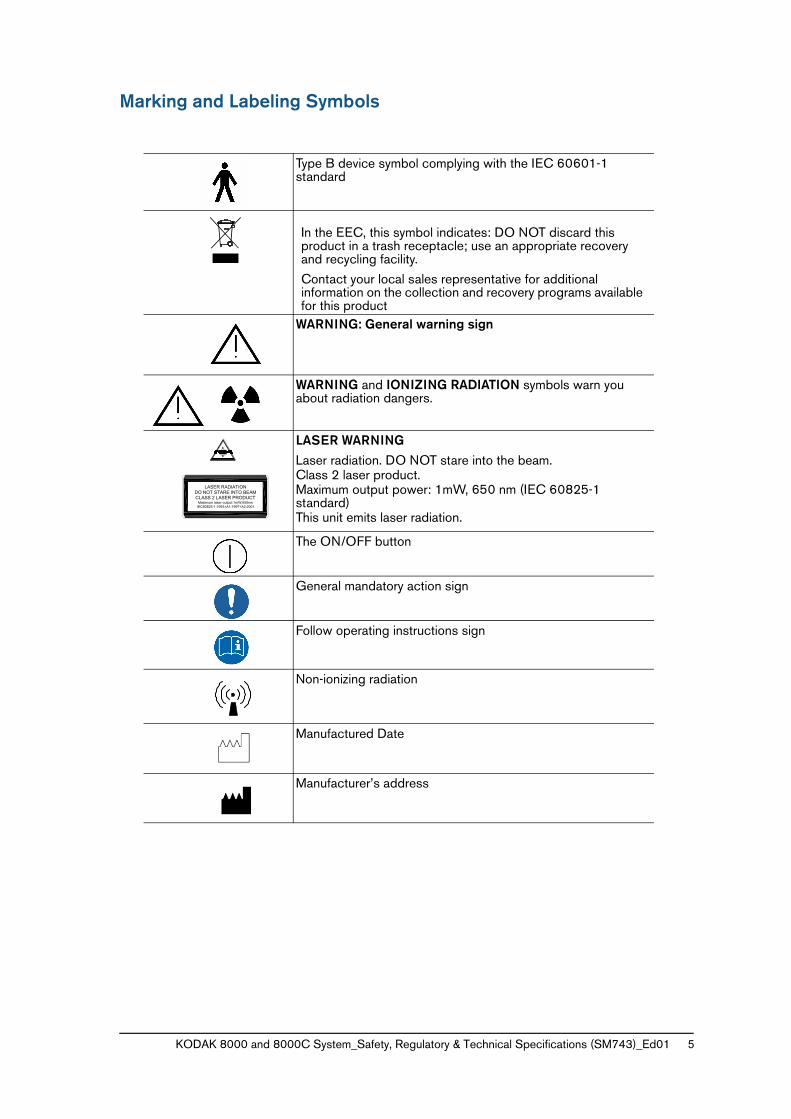
Marking and Labeling Symbols
Type B device symbol complying with the IEC 60601-1 standard
In the EEC, this symbol indicates: DO NOT discard this product in a trash receptacle; use an appropriate recovery and recycling facility.
Contact your local sales representative for additional information on the collection and recovery programs available for this product
WARNING: General warning sign
WARNING and IONIZING RADIATION symbols warn you about radiation dangers.
LASER WARNING
Laser radiation. DO NOT stare into the beam.Class 2 laser product.Maximum output power: 1mW, 650 nm (IEC 60825-1 standard)This unit emits laser radiation.
The ON/OFF button
General mandatory action sign
Follow operating instructions sign
Non-ionizing radiation
Manufactured Date
Manufacturer’s address
LASER RADIATIONDO NOT STARE INTO BEAMCLASS 2 LASER PRODUCT
Maximum laser output:1mW,650nmIEC60825-1:1993+A1:1997+A2:2001
6 Chapter 1 Safety Information
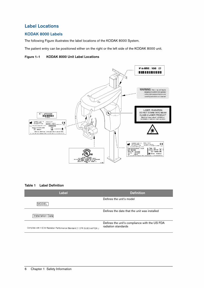
Label Locations
KODAK 8000 Labels
The following Figure illustrates the label locations of the KODAK 8000 System.
The patient entry can be positioned either on the right or the left side of the KODAK 8000 unit.
Figure 1–1 KODAK 8000 Unit Label Locations
Table 1 Label Definition
Label Definition
Defines the unit’s model
Defines the date that the unit was installed
Defines the unit’s compliance with the US FDA radiation standards
KODAK 8000 and 8000C System_Safety, Regulatory & Technical Specifications (SM743)_Ed01 7
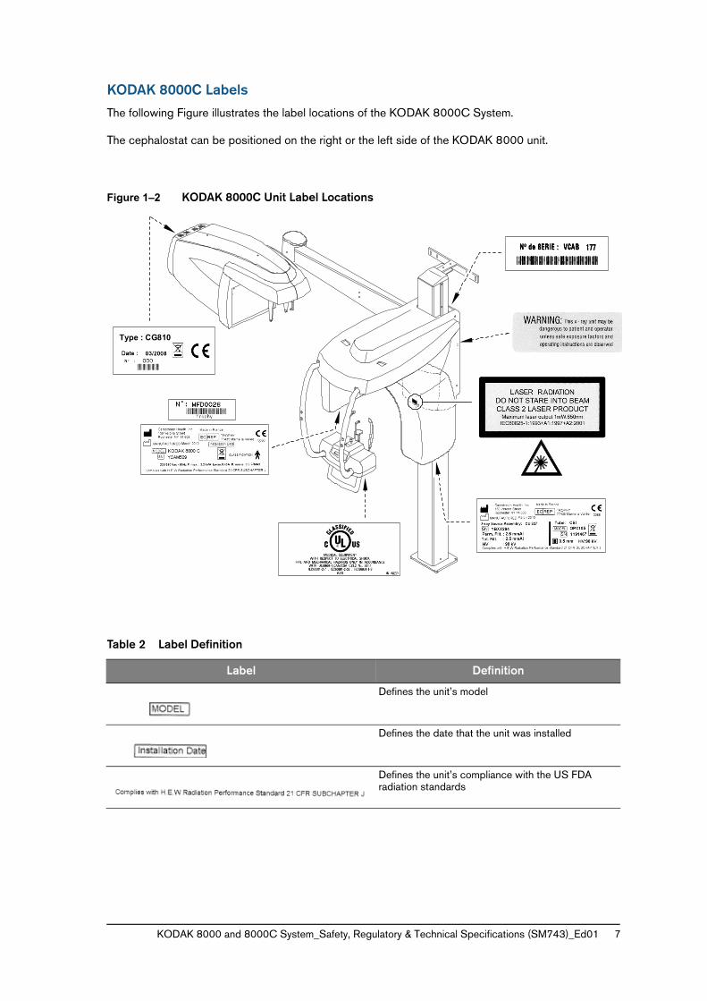
KODAK 8000C Labels
The following Figure illustrates the label locations of the KODAK 8000C System.
The cephalostat can be positioned on the right or the left side of the KODAK 8000 unit.
Figure 1–2 KODAK 8000C Unit Label Locations
Table 2 Label Definition
Label Definition
Defines the unit’s model
Defines the date that the unit was installed
Defines the unit’s compliance with the US FDA radiation standards
Type : CG810

8 Chapter 1 Safety Information
KODAK 8000 and 8000C System_Safety, Regulatory & Technical Specifications (SM743)_Ed01 9
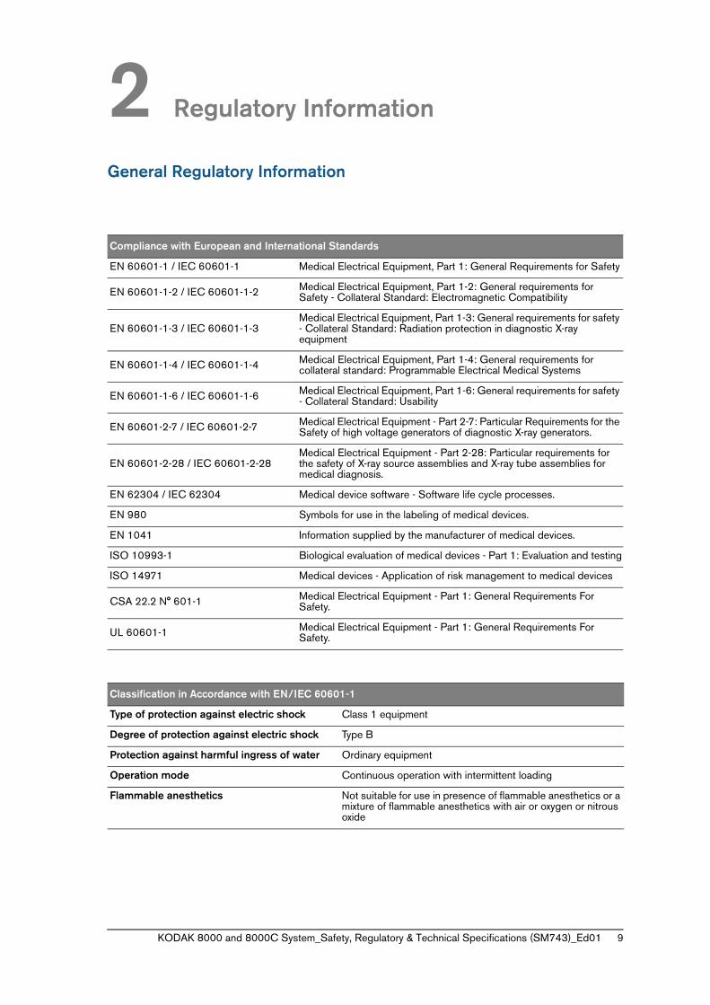
2 Regulatory Information
General Regulatory Information
Compliance with European and International Standards
EN 60601-1 / IEC 60601-1 Medical Electrical Equipment, Part 1: General Requirements for Safety
EN 60601-1-2 / IEC 60601-1-2 Medical Electrical Equipment, Part 1-2: General requirements for Safety - Collateral Standard: Electromagnetic Compatibility
EN 60601-1-3 / IEC 60601-1-3Medical Electrical Equipment, Part 1-3: General requirements for safety - Collateral Standard: Radiation protection in diagnostic X-ray equipment
EN 60601-1-4 / IEC 60601-1-4 Medical Electrical Equipment, Part 1-4: General requirements for collateral standard: Programmable Electrical Medical Systems
EN 60601-1-6 / IEC 60601-1-6 Medical Electrical Equipment, Part 1-6: General requirements for safety - Collateral Standard: Usability
EN 60601-2-7 / IEC 60601-2-7 Medical Electrical Equipment - Part 2-7: Particular Requirements for the Safety of high voltage generators of diagnostic X-ray generators.
EN 60601-2-28 / IEC 60601-2-28Medical Electrical Equipment - Part 2-28: Particular requirements for the safety of X-ray source assemblies and X-ray tube assemblies for medical diagnosis.
EN 62304 / IEC 62304 Medical device software - Software life cycle processes.
EN 980 Symbols for use in the labeling of medical devices.
EN 1041 Information supplied by the manufacturer of medical devices.
ISO 10993-1 Biological evaluation of medical devices - Part 1: Evaluation and testing
ISO 14971 Medical devices - Application of risk management to medical devices
CSA 22.2 N° 601-1 Medical Electrical Equipment - Part 1: General Requirements For Safety.
UL 60601-1 Medical Electrical Equipment - Part 1: General Requirements For Safety.
Classification in Accordance with EN/IEC 60601-1
Type of protection against electric shock Class 1 equipment
Degree of protection against electric shock Type B
Protection against harmful ingress of water Ordinary equipment
Operation mode Continuous operation with intermittent loading
Flammable anesthetics Not suitable for use in presence of flammable anesthetics or a mixture of flammable anesthetics with air or oxygen or nitrous oxide
10 Chapter 2 Regulatory Information
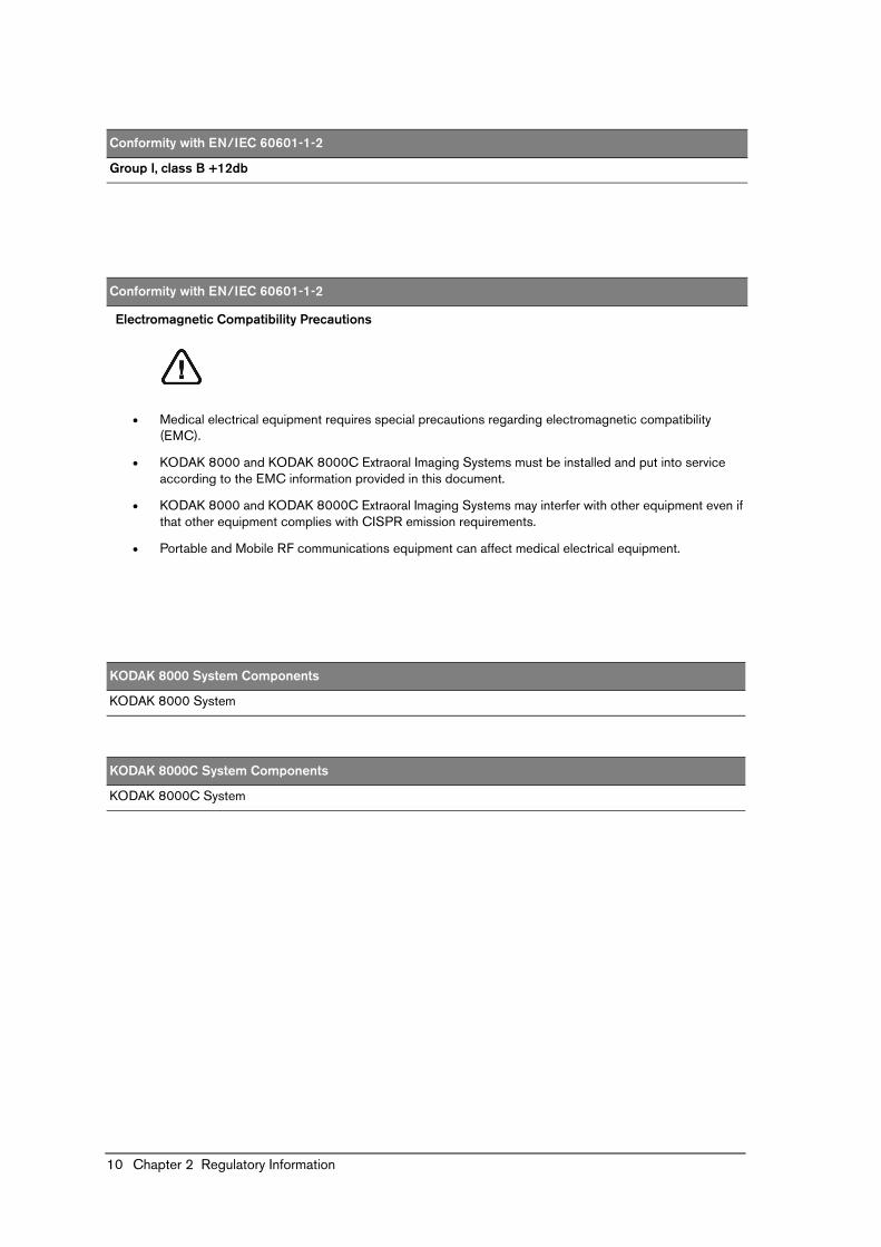
Electromagnetic Compatibility Precautions
• Medical electrical equipment requires special precautions regarding electromagnetic compatibility (EMC).
• KODAK 8000 and KODAK 8000C Extraoral Imaging Systems must be installed and put into service according to the EMC information provided in this document.
• KODAK 8000 and KODAK 8000C Extraoral Imaging Systems may interfer with other equipment even if that other equipment complies with CISPR emission requirements.
• Portable and Mobile RF communications equipment can affect medical electrical equipment.
Conformity with EN/IEC 60601-1-2
Group I, class B +12db
Conformity with EN/IEC 60601-1-2
Electromagnetic Compatibility Precautions
KODAK 8000 System Components
KODAK 8000 System
KODAK 8000C System Components
KODAK 8000C System
KODAK 8000 and 8000C System_Safety, Regulatory & Technical Specifications (SM743)_Ed01 11
• Use limitation: the use of accessories, cables, or transducers other than those specified in the user’s guide with the exception of cables, accessories or transducers sold by Carestream Health, Inc. as replacement parts of internal components, may result in increased emissions or decreased immunity of the KODAK 8000 and KODAK 8000C Extraoral Imaging Systems.
• The KODAK 8000 and KODAK 8000C Extraoral Imaging Systems should not be used adjacent to or stacked with other equipment. If adjacent or stacked use is necessary, the KODAK 8000 and KODAK 8000C Extraoral Imaging Systems should be observed to verify normal operation in the configuration in which it will be used.
Warning:
The room in which your radiology unit is to be installed must comply with all official regulations applicable to protection against radiation. you must install your radiology unit in a room protected against X-ray emission. this room must reduce to at least 12db the frequency interferences of the 30MHz to 1 GHz band (CISPR 11: 2003 + A1 2004).
12 Chapter 2 Regulatory Information
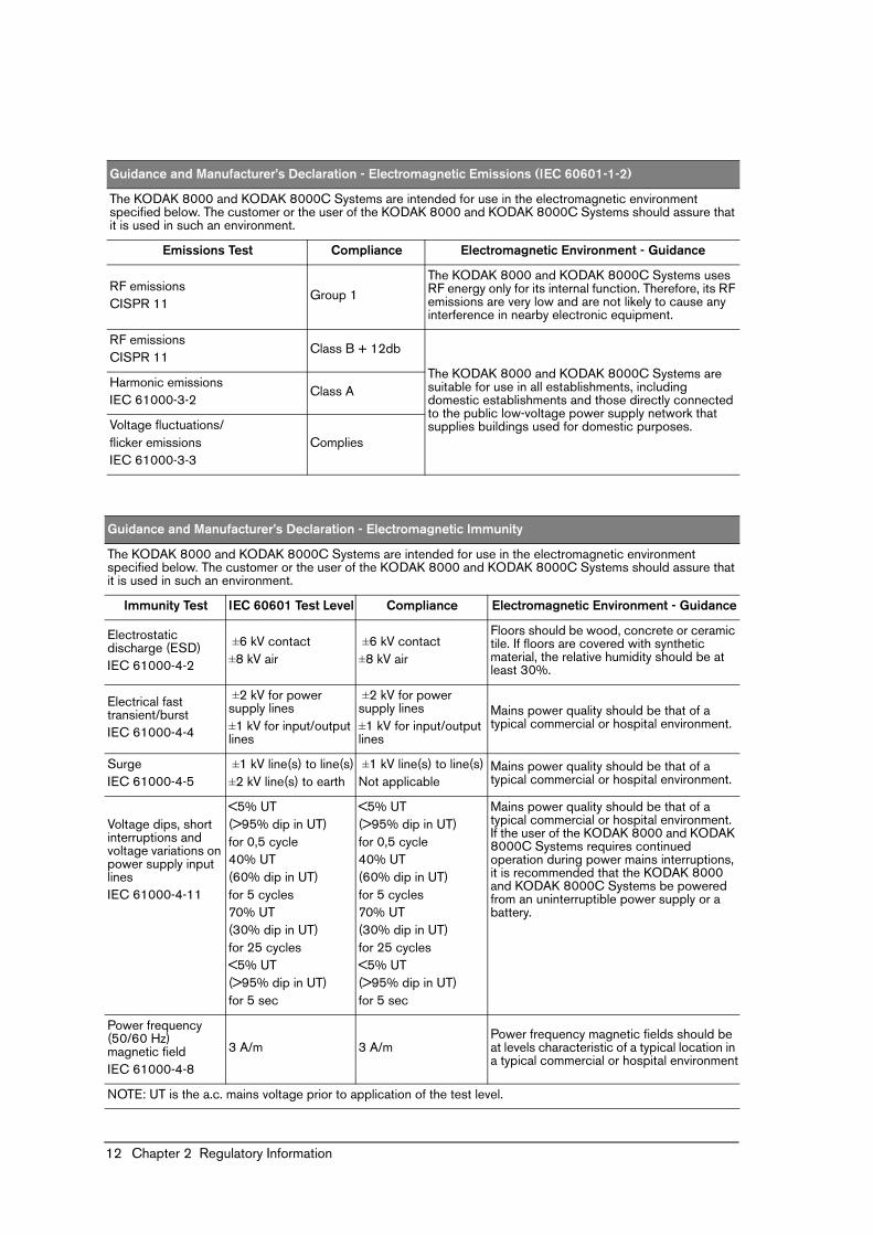
Guidance and Manufacturer’s Declaration - Electromagnetic Emissions (IEC 60601-1-2)
The KODAK 8000 and KODAK 8000C Systems are intended for use in the electromagnetic environment specified below. The customer or the user of the KODAK 8000 and KODAK 8000C Systems should assure that it is used in such an environment.
Emissions Test Compliance Electromagnetic Environment - Guidance
RF emissions CISPR 11
Group 1
The KODAK 8000 and KODAK 8000C Systems uses RF energy only for its internal function. Therefore, its RF emissions are very low and are not likely to cause any interference in nearby electronic equipment.
RF emissions CISPR 11
Class B + 12db
The KODAK 8000 and KODAK 8000C Systems are suitable for use in all establishments, including domestic establishments and those directly connected to the public low-voltage power supply network that supplies buildings used for domestic purposes.
Harmonic emissionsIEC 61000-3-2
Class A
Voltage fluctuations/flicker emissionsIEC 61000-3-3
Complies
Guidance and Manufacturer’s Declaration - Electromagnetic Immunity
The KODAK 8000 and KODAK 8000C Systems are intended for use in the electromagnetic environment specified below. The customer or the user of the KODAK 8000 and KODAK 8000C Systems should assure that it is used in such an environment.
Immunity Test IEC 60601 Test Level Compliance Electromagnetic Environment - Guidance
Electrostatic discharge (ESD)IEC 61000-4-2
±6 kV contact±8 kV air
±6 kV contact±8 kV air
Floors should be wood, concrete or ceramic tile. If floors are covered with synthetic material, the relative humidity should be at least 30%.
Electrical fast transient/burstIEC 61000-4-4
±2 kV for power supply lines±1 kV for input/output lines
±2 kV for power supply lines±1 kV for input/output lines
Mains power quality should be that of a typical commercial or hospital environment.
SurgeIEC 61000-4-5
±1 kV line(s) to line(s)±2 kV line(s) to earth
±1 kV line(s) to line(s)Not applicable
Mains power quality should be that of a typical commercial or hospital environment.
Voltage dips, short interruptions and voltage variations on power supply input linesIEC 61000-4-11
<5% UT (>95% dip in UT)for 0,5 cycle40% UT (60% dip in UT)for 5 cycles70% UT (30% dip in UT)for 25 cycles<5% UT (>95% dip in UT)for 5 sec
<5% UT (>95% dip in UT)for 0,5 cycle40% UT (60% dip in UT)for 5 cycles70% UT (30% dip in UT)for 25 cycles<5% UT (>95% dip in UT)for 5 sec
Mains power quality should be that of a typical commercial or hospital environment. If the user of the KODAK 8000 and KODAK 8000C Systems requires continued operation during power mains interruptions, it is recommended that the KODAK 8000 and KODAK 8000C Systems be powered from an uninterruptible power supply or a battery.
Power frequency (50/60 Hz) magnetic fieldIEC 61000-4-8
3 A/m 3 A/mPower frequency magnetic fields should be at levels characteristic of a typical location in a typical commercial or hospital environment
NOTE: UT is the a.c. mains voltage prior to application of the test level.
KODAK 8000 and 8000C System_Safety, Regulatory & Technical Specifications (SM743)_Ed01 13
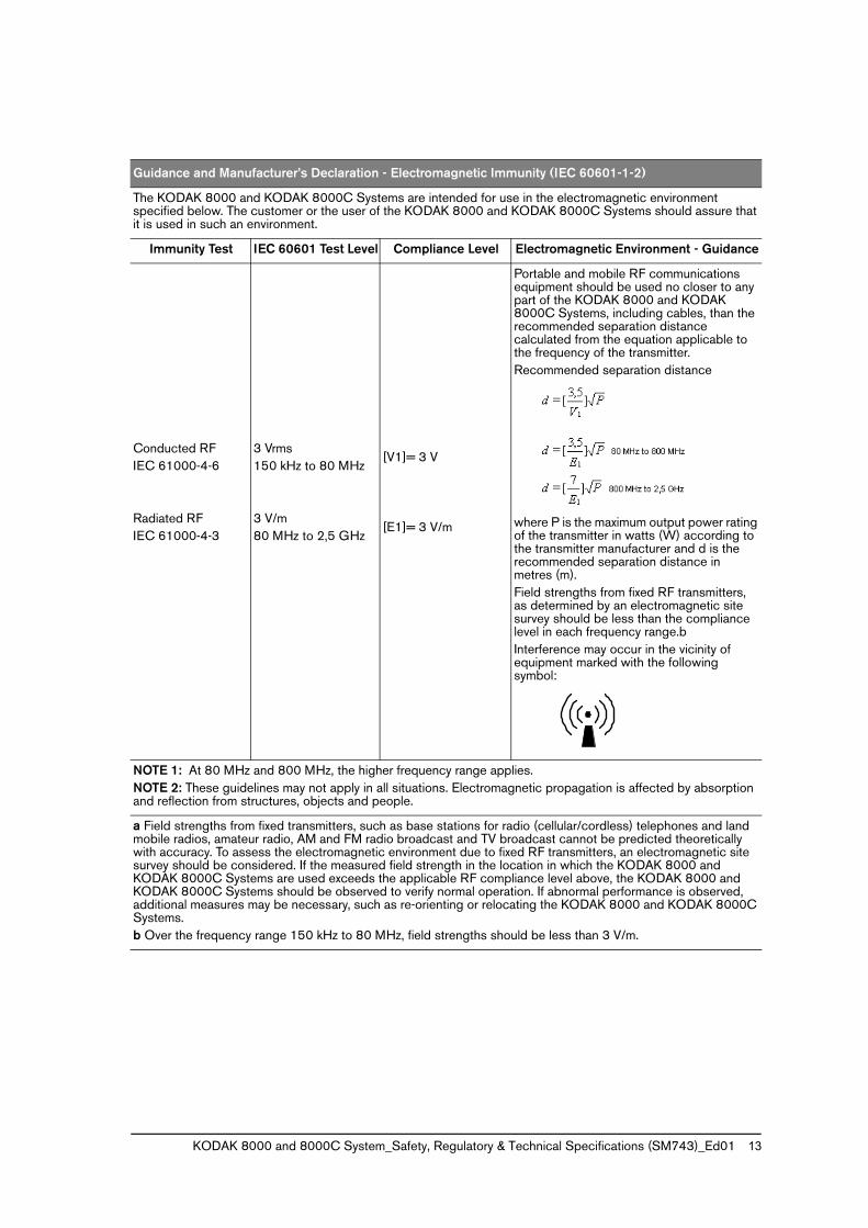
Guidance and Manufacturer’s Declaration - Electromagnetic Immunity (IEC 60601-1-2)
The KODAK 8000 and KODAK 8000C Systems are intended for use in the electromagnetic environment specified below. The customer or the user of the KODAK 8000 and KODAK 8000C Systems should assure that it is used in such an environment.
Immunity Test IEC 60601 Test Level Compliance Level Electromagnetic Environment - Guidance
Conducted RF IEC 61000-4-6
Radiated RFIEC 61000-4-3
3 Vrms150 kHz to 80 MHz
3 V/m80 MHz to 2,5 GHz
[V1]= 3 V
[E1]= 3 V/m
Portable and mobile RF communications equipment should be used no closer to any part of the KODAK 8000 and KODAK 8000C Systems, including cables, than the recommended separation distance calculated from the equation applicable to the frequency of the transmitter. Recommended separation distance
where P is the maximum output power rating of the transmitter in watts (W) according to the transmitter manufacturer and d is the recommended separation distance in metres (m).Field strengths from fixed RF transmitters, as determined by an electromagnetic site survey should be less than the compliance level in each frequency range.b Interference may occur in the vicinity of equipment marked with the following symbol:
NOTE 1: At 80 MHz and 800 MHz, the higher frequency range applies.NOTE 2: These guidelines may not apply in all situations. Electromagnetic propagation is affected by absorption and reflection from structures, objects and people.
a Field strengths from fixed transmitters, such as base stations for radio (cellular/cordless) telephones and land mobile radios, amateur radio, AM and FM radio broadcast and TV broadcast cannot be predicted theoretically with accuracy. To assess the electromagnetic environment due to fixed RF transmitters, an electromagnetic site survey should be considered. If the measured field strength in the location in which the KODAK 8000 and KODAK 8000C Systems are used exceeds the applicable RF compliance level above, the KODAK 8000 and KODAK 8000C Systems should be observed to verify normal operation. If abnormal performance is observed, additional measures may be necessary, such as re-orienting or relocating the KODAK 8000 and KODAK 8000C Systems.b Over the frequency range 150 kHz to 80 MHz, field strengths should be less than 3 V/m.
14 Chapter 2 Regulatory Information
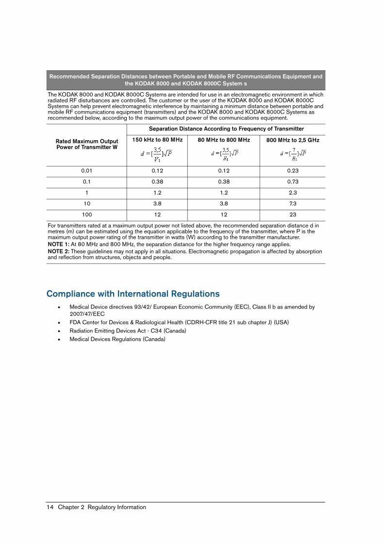
Compliance with International Regulations• Medical Device directives 93/42/ European Economic Community (EEC), Class II b as amended by
2007/47/EEC• FDA Center for Devices & Radiological Health (CDRH-CFR title 21 sub chapter J) (USA)• Radiation Emitting Devices Act - C34 (Canada)• Medical Devices Regulations (Canada)
Recommended Separation Distances between Portable and Mobile RF Communications Equipment and the KODAK 8000 and KODAK 8000C System s
The KODAK 8000 and KODAK 8000C Systems are intended for use in an electromagnetic environment in which radiated RF disturbances are controlled. The customer or the user of the KODAK 8000 and KODAK 8000C Systems can help prevent electromagnetic interference by maintaining a minimum distance between portable and mobile RF communications equipment (transmitters) and the KODAK 8000 and KODAK 8000C Systems as recommended below, according to the maximum output power of the communications equipment.
Rated Maximum Output Power of Transmitter W
Separation Distance According to Frequency of Transmitter
150 kHz to 80 MHz 80 MHz to 800 MHz 800 MHz to 2,5 GHz
0.01 0.12 0.12 0.23
0.1 0.38 0.38 0.73
1 1.2 1.2 2.3
10 3.8 3.8 7.3
100 12 12 23
For transmitters rated at a maximum output power not listed above, the recommended separation distance d in metres (m) can be estimated using the equation applicable to the frequency of the transmitter, where P is the maximum output power rating of the transmitter in watts (W) according to the transmitter manufacturer.NOTE 1: At 80 MHz and 800 MHz, the separation distance for the higher frequency range applies.NOTE 2: These guidelines may not apply in all situations. Electromagnetic propagation is affected by absorption and reflection from structures, objects and people.
KODAK 8000 and 8000C System_Safety, Regulatory & Technical Specifications (SM743)_Ed01 15
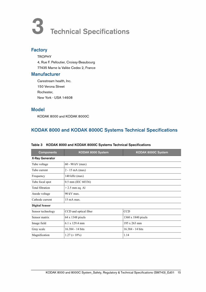
3 Technical Specifications
FactoryTROPHY
4, Rue F. Pelloutier, Croissy-Beaubourg
77435 Marne la Vallée Cedex 2, France
ManufacturerCarestream health, Inc.
150 Verona Street
Rochester,
New York - USA 14608
ModelKODAK 8000 and KODAK 8000C
KODAK 8000 and KODAK 8000C Systems Technical Specifications
Table 3 KODAK 8000 and KODAK 8000C Systems Technical Specifications
Components KODAK 8000 System KODAK 8000C System
X-Ray Generator
Tube voltage 60 - 90 kV (max)
Tube current 2 - 15 mA (max)
Frequency 140 kHz (max)
Tube focal spot 0.5 mm (IEC 60336)
Total filtration > 2.5 mm eq. Al
Anode voltage 90 kV max.
Cathode current 15 mA max.
Digital Sensor
Sensor technology CCD and optical fiber CCD
Sensor matrix 64 x 1348 pixels 1360 x 1840 pixels
Image field 6.1 x 129.4 mm 195 x 263 mm
Gray scale 16.384 - 14 bits 16.384 - 14 bits
Magnification 1.27 (± 10%) 1.14
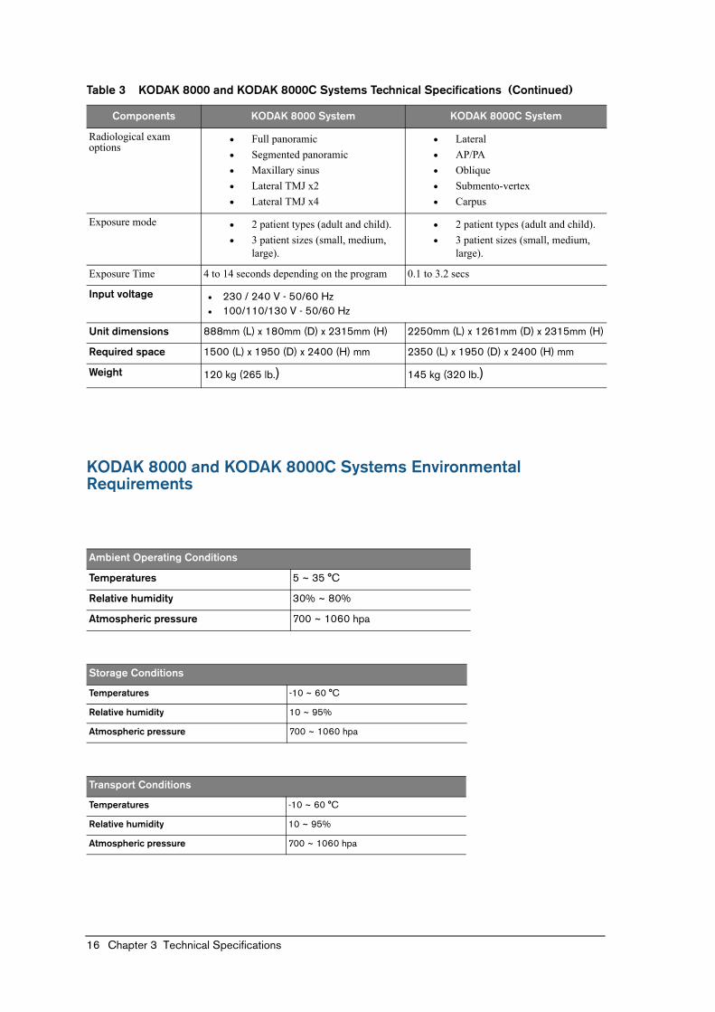
16 Chapter 3 Technical Specifications
KODAK 8000 and KODAK 8000C Systems Environmental Requirements
Radiological exam options
• Full panoramic• Segmented panoramic• Maxillary sinus• Lateral TMJ x2• Lateral TMJ x4
• Lateral• AP/PA• Oblique• Submento-vertex• Carpus
Exposure mode • 2 patient types (adult and child).• 3 patient sizes (small, medium,
large).
• 2 patient types (adult and child).• 3 patient sizes (small, medium,
large).
Exposure Time 4 to 14 seconds depending on the program 0.1 to 3.2 secs
Input voltage • 230 / 240 V - 50/60 Hz • 100/110/130 V - 50/60 Hz
Unit dimensions 888mm (L) x 180mm (D) x 2315mm (H) 2250mm (L) x 1261mm (D) x 2315mm (H)
Required space 1500 (L) x 1950 (D) x 2400 (H) mm 2350 (L) x 1950 (D) x 2400 (H) mm
Weight 120 kg (265 lb.) 145 kg (320 lb.)
Ambient Operating Conditions
Temperatures 5 ~ 35 °C
Relative humidity 30% ~ 80%
Atmospheric pressure 700 ~ 1060 hpa
Storage Conditions
Temperatures -10 ~ 60 °C
Relative humidity 10 ~ 95%
Atmospheric pressure 700 ~ 1060 hpa
Transport Conditions
Temperatures -10 ~ 60 °C
Relative humidity 10 ~ 95%
Atmospheric pressure 700 ~ 1060 hpa
Table 3 KODAK 8000 and KODAK 8000C Systems Technical Specifications (Continued)
Components KODAK 8000 System KODAK 8000C System
KODAK 8000 and 8000C System_Safety, Regulatory & Technical Specifications (SM743)_Ed01 17
KODAK 8000 and KODAK 8000C Systems Electrical Specifications
Type of Electrical Power Supply230/240 V (± 10%) 50/60 Hz,
Single-Phase100/110/130V (± 10%) 50/60 Hz,
Single-Phase
Acceptable fluctuation ± 10% ± 10%
Apparent resistance of the power supply circuit
0.5 (max.) 0.12 (max.)
Permanent absorbed current 1.0 A 1.0 A
Current absorbed during the X-ray emission
10 A 20 A
Maximum absorbed power 2.2 kVA 2.2 kVA
Protection for the power supply system
By shutter release at a maximum current of 16A and a differential current of 30 mA
By shutter release at a maximum current of 20A and a differential current of 30 mA
Nominal high voltage 90 kV 90 kV
Maximum corresponding tube current
10 mA 10 mA
Nominal tube current 15 mA 15 mA
Maximum corresponding high voltage
80 kV 68 kV
Tube current/voltage combination for maximum output power
80 kV, 15 mA 85 kV, 12 mA
Nominal power for an exposure time of 0.1 s.
at 80 kV, 15 mA: 1200 W at 85 kV, 12 mA: 1020 W
Utilization Rate in Continuous Mode (for example: one exposure - 85 kV, 5mA - 13.9 second, every 3 minutes)
Utilization Rate in Intermittent Mode (for example: one exposure - 80 kV, 15 mA - 13.9 second, every 3 minutes)
33 W 93 W
Selection of the Load Parameters:
kV (in increments of 1 kV) From 60 to 90 kV
mA (in increments of 25%) From 2 to 15 mA
Cooling Conditions
Maximum dissipation of heat from the X-ray radiogenic assembly into the ambient air (for utilization rate in continuous mode)
33 W
Ω Ω
18 Chapter 3 Technical Specifications
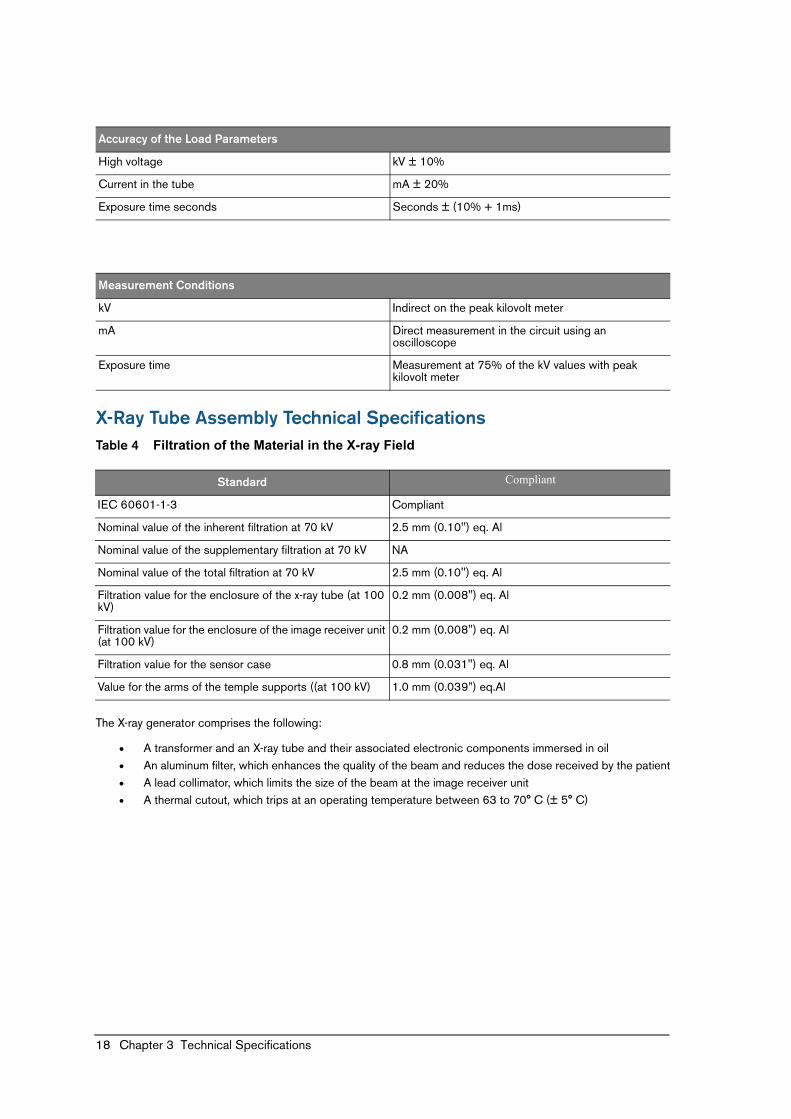
X-Ray Tube Assembly Technical SpecificationsTable 4 Filtration of the Material in the X-ray Field
The X-ray generator comprises the following:
• A transformer and an X-ray tube and their associated electronic components immersed in oil• An aluminum filter, which enhances the quality of the beam and reduces the dose received by the patient• A lead collimator, which limits the size of the beam at the image receiver unit• A thermal cutout, which trips at an operating temperature between 63 to 70° C (± 5° C)
Accuracy of the Load Parameters
High voltage kV ± 10%
Current in the tube mA ± 20%
Exposure time seconds Seconds ± (10% + 1ms)
Measurement Conditions
kV Indirect on the peak kilovolt meter
mA Direct measurement in the circuit using an oscilloscope
Exposure time Measurement at 75% of the kV values with peak kilovolt meter
Standard Compliant
IEC 60601-1-3 Compliant
Nominal value of the inherent filtration at 70 kV 2.5 mm (0.10'') eq. Al
Nominal value of the supplementary filtration at 70 kV NA
Nominal value of the total filtration at 70 kV 2.5 mm (0.10'') eq. Al
Filtration value for the enclosure of the x-ray tube (at 100 kV)
0.2 mm (0.008") eq. Al
Filtration value for the enclosure of the image receiver unit (at 100 kV)
0.2 mm (0.008") eq. Al
Filtration value for the sensor case 0.8 mm (0.031") eq. Al
Value for the arms of the temple supports ((at 100 kV) 1.0 mm (0.039”) eq.Al
KODAK 8000 and 8000C System_Safety, Regulatory & Technical Specifications (SM743)_Ed01 19
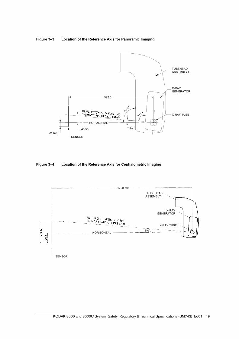
Figure 3–3 Location of the Reference Axis for Panoramic Imaging
Figure 3–4 Location of the Reference Axis for Cephalometric Imaging
F
5.0°45.50
522.0
TUBEHEADASSEMBLY1
X-RAYGENERATOR
X-RAY TUBE
HORIZONTAL
SENSOR24.50
1720 mm
TUBEHEADASSEMBLY1
X-RAYGENERATOR
X-RAY TUBE
5.0°HORIZONTAL
SENSOR
20 Chapter 3 Technical Specifications
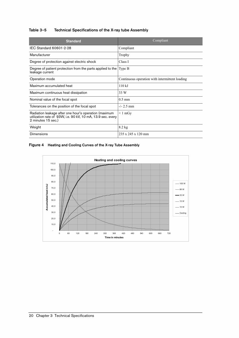
Table 3–5 Technical Specifications of the X-ray tube Assembly
Figure 4 Heating and Cooling Curves of the X-ray Tube Assembly
Standard Compliant
IEC Standard 60601-2-28 Compliant
Manufacturer Trophy
Degree of protection against electric shock Class I
Degree of patient protection from the parts applied to the leakage current
Type B
Operation mode Continuous operation with intermittent loading
Maximum accumulated heat 110 kJ
Maximum continuous heat dissipation 33 W
Nominal value of the focal spot 0.5 mm
Tolerances on the position of the focal spot -/- 2.5 mm
Radiation leakage after one hour's operation (maximum utilization rate of 93W, i.e. 90 kV, 10 mA, 13.9 sec. every 2 minutes 15 sec.)
< 1 mGy
Weight 8.2 kg
Dimensions 235 x 245 x 120 mm
Heating and cooling curves
-
10,0
20,0
30,0
40,0
50,0
60,0
70,0
80,0
90,0
100,0
110,0
0 60 120 180 240 300 360 420 480 540 600 660 720
Time in minutes
Acc
umul
ated
hea
t in
kJ
100 W
66 W
33 W
15 W
10 W
Cooling
KODAK 8000 and 8000C System_Safety, Regulatory & Technical Specifications (SM743)_Ed01 21
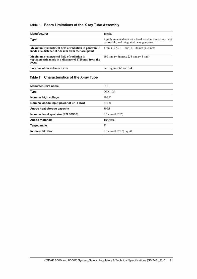
Table 6 Beam Limitations of the X-ray Tube Assembly
Table 7 Characteristics of the X-ray Tube
Manufacturer Trophy
Type Rigidly mounted unit with fixed window dimensions, not removable, and integrated x-ray generator
Maximum symmetrical field of radiation in panoramic mode at a distance of 522 mm from the focal point
4 mm (- 0.5 / + 1 mm) x 128 mm (± 2 mm)
Maximum symmetrical field of radiation in cephalometric mode at a distance of 1720 mm from the focus
190 mm (± 8mm) x 258 mm (± 8 mm)
Location of the reference axis See Figures 3-3 and 3-4
Manufacturer’s name CEI
Type OPX 105
Nominal high voltage 90 kV
Nominal anode input power at 0.1 s (AC) 810 W
Anode heat storage capacity 30 kJ
Nominal focal spot size (EN 60336) 0.5 mm (0.020'')
Anode materials Tungsten
Target angle 5°
Inherent filtration 0.5 mm (0.020 ") eq. Al
22 Chapter 3 Technical Specifications
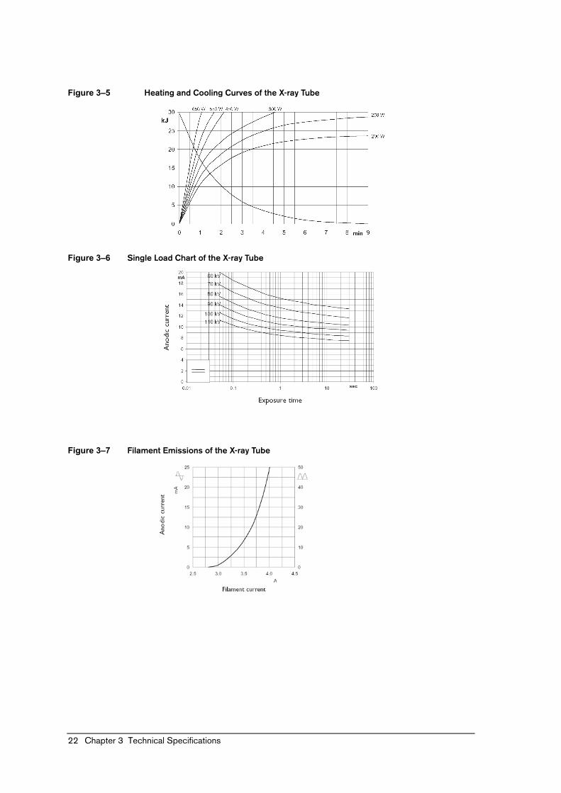
Figure 3–5 Heating and Cooling Curves of the X-ray Tube
Figure 3–6 Single Load Chart of the X-ray Tube
Figure 3–7 Filament Emissions of the X-ray Tube