Embed Size (px)
Citation preview
PUBLIC
KONGSBERG PROPRIETARY. This document and its accompanying elements contain
KONGSBERG information which is proprietary and confidential. Any disclosure, copying, distribution
or use is prohibited if not otherwise explicitly agreed with KONGSBERG in writing. Any authorized
reproduction, in whole or in part, must include this legend. ©2019 KONGSBERG - All rights reserved.
Kongsberg SBP 29
Sub-bottom Profiler
Product Description
Doc No: 447542
Revision: A
Status: Issued for use
Kongsberg Maritime AS PUBLIC
KONGSBERG PROPRIETARY – see Statement of Proprietary Information
447542 / A / March 2019/ Page 2 of 38
Document history
Revision Description of Change
A First Issue
Copyright
© Copyright Kongsberg Maritime AS
The information contained in this document remains the sole property of Kongsberg
Maritime AS. No part of this document may be copied or reproduced in any form or by
any means, and the information contained within it is not to be communicated to a third
party, without the prior written consent of Kongsberg Maritime AS. The document, or
any part of it, may not be translated to any other language without the written approval
from Kongsberg Maritime AS.
Disclaimer
Kongsberg Maritime AS endeavours to ensure that all information in this document is
correct and fairly stated, but does not accept liability for any errors or omissions.
Warning
The equipment to which this manual applies must only be used for the purpose for
which it was designed. Improper use or maintenance may cause damage to the
equipment and/or injury to personnel. All users must be familiar with the contents of the
appropriate manuals before attempting to install, operate, maintain or in any other way
work on the equipment.
Kongsberg Maritime AS disclaims any responsibility for damage or injury caused by
improper installation, use or maintenance of the equipment.
Support information
If you require maintenance or repair, contact your local dealer. You can also contact us
using the following address: [email protected]. If you need
information about our other products, visit http://www.km.kongsberg.com.

Kongsberg Maritime AS PUBLIC
KONGSBERG PROPRIETARY – see Statement of Proprietary Information
447542 / A / March 2019/ Page 3 of 38
Table of contents
1 Kongsberg SBP 29 .................................................................................................. 5
1.1 System description ................................................................................................... 6
1.2 Key specifications .................................................................................................... 7
1.3 System diagram ........................................................................................................ 9
1.4 Transducer description ........................................................................................... 10
1.5 Transceiver unit (TRU) .......................................................................................... 11
1.6 Operator Station ..................................................................................................... 11
1.7 Support information ............................................................................................... 12
2 Performance.......................................................................................................... 13
2.1 Penetration.............................................................................................................. 14
2.1.1 Examples of achieved penetration ........................................................... 14
2.2 Beam steering ......................................................................................................... 17
2.2.1 Stabilisation of pitch and roll ................................................................... 17
2.2.2 Multiple simultaneous beams .................................................................. 17
2.2.3 Active beam steering in sloping terrain ................................................... 18
2.3 Ping rate ................................................................................................................. 22
2.4 Steering of acquisition window .............................................................................. 22
2.5 Operating modes .................................................................................................... 22
2.6 Data logging and real-time processing ................................................................... 24
2.7 The transmit array .................................................................................................. 24
3 Installation ............................................................................................................ 25
3.1 Operator station ...................................................................................................... 25
3.2 K-Rem remote control............................................................................................ 25
3.3 Electronic cabinets ................................................................................................. 25
3.4 Transducer arrays ................................................................................................... 25
3.5 Ice Protection Windows ......................................................................................... 26
4 Scope of supply ..................................................................................................... 27
4.1 Standard supply ...................................................................................................... 27
Kongsberg Maritime AS PUBLIC
KONGSBERG PROPRIETARY – see Statement of Proprietary Information
447542 / A / March 2019/ Page 4 of 38
4.2 Optional supply ...................................................................................................... 27
4.3 System integration .................................................................................................. 27
5 Operation .............................................................................................................. 28
5.1 System control ........................................................................................................ 28
5.2 Operating system .................................................................................................... 28
5.3 Parameter settings .................................................................................................. 29
6 Technical specifications ....................................................................................... 30
6.1 System performance (3/6/12 deg) .......................................................................... 30
6.2 List of units and sub-units ...................................................................................... 31
6.3 Interfaces ................................................................................................................ 31
6.4 Physical specifications ........................................................................................... 32
6.5 Power requirements ................................................................................................ 33
6.6 Restriction for use .................................................................................................. 34
6.7 Operating and storage temperature ........................................................................ 34
6.8 Surface finish ......................................................................................................... 34
6.9 Environmental specifications ................................................................................. 34
6.10 Transceiver Unit outline dimensions ..................................................................... 35
7 Customer support ................................................................................................ 36
7.1 Installation .............................................................................................................. 36
7.2 Documentation and training ................................................................................... 36
7.3 Service .................................................................................................................... 37
7.4 FEMME ................................................................................................................. 37
7.5 Warranty and maintenance contract ....................................................................... 37
8 KM Sub-bottom profilers .................................................................................... 38
Kongsberg Maritime AS PUBLIC
KONGSBERG PROPRIETARY – see Statement of Proprietary Information
447542 / A / March 2019/ Page 5 of 38
1 Kongsberg SBP 29
Topics System description on page 6
Key specifications on page 7
System diagram on page 9
Transducer description on page 10
Transceiver unit (TRU) on page 11
Operator Station on page 11
Support information on page 12
Kongsberg Maritime AS PUBLIC
KONGSBERG PROPRIETARY – see Statement of Proprietary Information
447542 / A / March 2019/ Page 6 of 38
1.1 System description
The SBP 29 is the next generation narrow beam, multibeam sub-bottom profiler, and is
the successor of the SBP 120 and SBP 300. The system has new and improved
technology, wider bandwidth 2 – 9 kHz and accordingly improved range resolution.
The primary application of the SBP 29 is to do sub-bottom imaging of sediment layers
and buried objects. The data can be stored as raw or in SEG-Y format.
Key features of the SBP 29 are:
High source level. Can be reduced by 30 dB in steps of 1 dB.
Narrow beams giving improved penetration, cleaner data, and good angular
resolution.
Wider beams can be made when desired.
A swath of beams can be generated per ping, offering acrosstrack slope
robustness. This swath is also useful for detection of buried objects and studies
of backscatter.
Transmit modes for use when narrow beams are unfavourable:
o Cyclic variation of beam width
o Cyclic variation of alongtrack beam tilt (volume scanning)
Typically operated in parallel with the EM system, either synchronized or
unsynchronized.
Burst and multi-pulse modes to maintain a high ping rate in deep water
The array geometry of the SBP 29 is the same as that used by the EM multibeam echo
sounders. For reception, it uses the wideband receive antenna of the EM system. With
much narrower beam widths than conventional sub-bottom profilers, the SBP 29
provides superior specular return to backscatter ratio and thereby improved penetration
and less cluttered imaging. SBP 29 comes as 3, 6 or 12 degrees transmitting array
system.
For the three-degree transmitter, the frequency dependent source level is above 224 dB
re 1 μPa @ 1m between 3.5 kHz and 6.5 kHz.
The SBP 29 beams are electronically stabilized for roll and pitch, and the data are heave
compensated. The system has several advantages when encountering sloping sediments
compared to other systems:
For each ping a swath of beams can be made that cover the across track footprint
of the transmitter, making the system tolerant to across track slopes.
It is possible to operate with wider beams, trading slope robustness for signal
quality.
Kongsberg Maritime AS PUBLIC
KONGSBERG PROPRIETARY – see Statement of Proprietary Information
447542 / A / March 2019/ Page 7 of 38
In addition, two transmit modes are implemented as tools when sloping sediments is a
problem:
One transmit mode allows cyclic variation of the beam widths. In this manner
echograms imaging the sub-bottom with narrow and wide beams can be
collected in a single pass. When sloping sediments are missing in the narrow
beam echogram, this information can be found in the wide beam.
The other transmit mode offers volume scanning with narrow beams. By
combining information from all beams in a scan, a composite echogram can be
made with the slope robustness of a wide beam system and the data quality of a
narrow beam system.
1.2 Key specifications
The SBP 29 has significantly reduced beam widths compared to conventional sub-
bottom profilers. This is obtained by one linear transmitter array mounted along the
vessel keel, and one linear hydrophone array (shared with the EM 124/304) mounted
orthogonal to the keel. The footprint of the transmitter array is wide acrosstrack and
narrow alongtrack, whereas the opposite is the case for the receiver array. The
combined beam pattern of the two arrays is a narrow beam.
Some of the consequences of using large arrays are:
The larger the transmitter array, the more power can be injected (without risking
cavitation). This implies an increased source level.
The directivity of the transmitter also increases with the size of the transmitter,
which implies a further increase of the source level.
The reverberation volume is greatly reduced with reduced beam widths. (The
reverberation volume roughly increases with the square of the beamwidth.)
The increased directivity of the SBP 29 receiver array compared to smaller
receivers improves the suppression of acoustic noise.
Because the transmit beam is wide acrosstrack and all hydrophones are sampled
individually, the SBP 29 can make a fan of narrow beams acrosstrack per ping. This
multibeam capability of the SBP 29 is useful for:
Finding the specular return(s) in rough terrain despite the narrow beams.
Resolving lateral specular returns in rough terrain
Detecting buried objects
Obtaining information about the sloping angle of sediments (which sometimes
changes with range and may be completely different from that of the sea floor)
Kongsberg Maritime AS PUBLIC
KONGSBERG PROPRIETARY – see Statement of Proprietary Information
447542 / A / March 2019/ Page 8 of 38
The normal transmit waveform is a linear chirp. The outer limits for the start and stop
frequencies of the chirp are 2 to 9 kHz, providing a maximum vertical resolution of
approximately 0.2 milliseconds. In addition to linear chirps, the transmitter offers CW
pulses, hyperbolic chirps and Ricker pulses.
The transmit array of the SBP 29 is offered in three, six or twelve degree versions. The
frequency dependent source level of a three-degree transmitter is typically above 220
dB re 1 μPa @ 1 m. The peak electrical power consumption is less than 14 kW for the
largest system.
Normally the SBP 29 transmit antenna is matched with a receive antenna of similar
physical size, but it is possible to combine any SBP 29 transmit antenna with any EM
124/304 receiver antenna.
Kongsberg Maritime AS PUBLIC
KONGSBERG PROPRIETARY – see Statement of Proprietary Information
447542 / A / March 2019/ Page 9 of 38
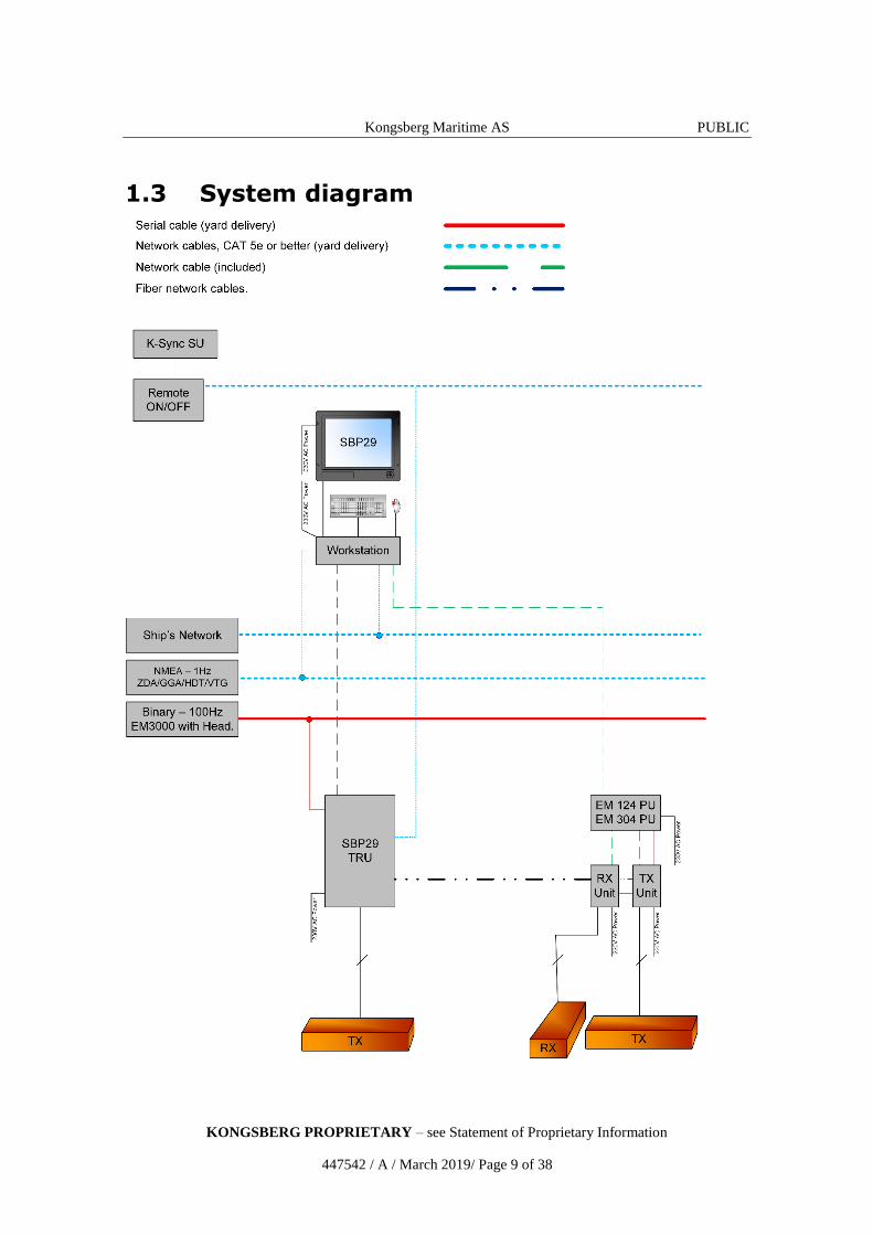
1.3 System diagram
Kongsberg Maritime AS PUBLIC
KONGSBERG PROPRIETARY – see Statement of Proprietary Information
447542 / A / March 2019/ Page 10 of 38
1.4 Transducer description
A transducer is a device that converts one form of energy to another. In a sub-bottom
profiler system, the transducer converts between electric energy and sound.
The SBP 29 transmit transducer has a physical width of 80 cm, a depth of 35 cm and a
length depending on the requested beamwidth. The 3º, 6º, and 12º SBP 29 transmit
arrays are 7.5, 3.8 and 1.9 meters long, respectively.
The transmit array is mounted in parallel with the vessel’s keel, normally side by side
with the multibeam echo sounder’s transmit array. For a “best performance” SBP 29
system one should always select a three-degree transmitter, but normally it will be
inconvenient to have an SBP transmitter much longer than the EM transmitter.
The lengths of the 0.5º, 1º and 2º EM 124 transmitter are 15.2, 7.8 and 4 meters,
respectively.
The lengths of the 0.5º, 1º and 2º EM 304 transmitter are 6.0, 3.0 and 1.5 meters,
respectively.
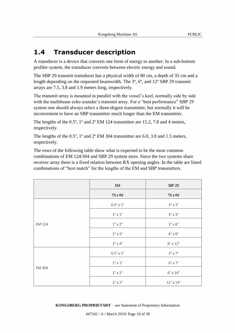
The rows of the following table show what is expected to be the most common
combinations of EM 124/304 and SBP 29 system sizes. Since the two systems share
receiver array there is a fixed relation between RX opening angles. In the table are listed
combinations of “best match” for the lengths of the EM and SBP transmitters.
EM SBP 29
TX x RX TX x RX
EM 124
0.5° x 1° 3° x 3°
1° x 1° 3° x 3°
1° x 2° 3° x 6°
2° x 2° 6° x 6°
2° x 4° 6° x 12°
EM 304
0.5° x 1° 3° x 7°
1° x 1° 6° x 7°
1° x 2° 6° x 14°
2° x 2° 12° x 14°
Kongsberg Maritime AS PUBLIC
KONGSBERG PROPRIETARY – see Statement of Proprietary Information
447542 / A / March 2019/ Page 11 of 38
1.5 Transceiver unit (TRU)
The electronic circuitry required for the SBP 29 Sub-bottom profiler is housed in a
separate cabinet called the transceiver unit (TRU). The TRU holds all transmit and
receive electronics for the SBP 29 TX, like power amplifiers, power supply, capacitor
battery and Ethernet interface.
The Transceiver Unit is a wall-mounted steel cabinet with integrated shock and
vibration absorbers, designed for bulkhead mounting. Two 19-inch sub-racks are
contained in the cabinet. The number of circuit boards in the sub-racks will depend
upon the chosen system configuration.
A fibre cable is used for sending an SBP TX active signal from the SBP 29 to the EM
124/304 Receiver Unit.
The TRU receives ships attitude, and has interfaces for synchronization with the EM
124/304 and K-Sync.
Ethernet is used for data communication with the Operator Station.
The Transmitter Units are normally located in a "sonar room" close to the transducer
arrays
1.6 Operator Station
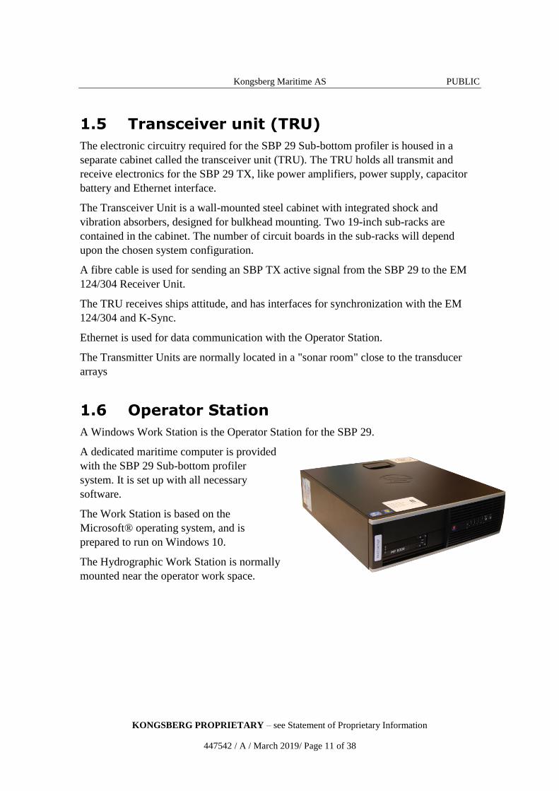
A Windows Work Station is the Operator Station for the SBP 29.
A dedicated maritime computer is provided
with the SBP 29 Sub-bottom profiler
system. It is set up with all necessary
software.
The Work Station is based on the
Microsoft® operating system, and is
prepared to run on Windows 10.
The Hydrographic Work Station is normally
mounted near the operator work space.

Kongsberg Maritime AS PUBLIC
KONGSBERG PROPRIETARY – see Statement of Proprietary Information
447542 / A / March 2019/ Page 12 of 38
1.7 Support information
Should you need technical support for your SBP 29 please contact a Kongsberg
Maritime office. A list of all our offices is provided on our website. You can also
contact our main support office in Norway.
Company name: Kongsberg Maritime AS
Address: Strandpromenaden 50, 3190 Horten, Norway
Telephone (24h support): +47 33 03 24 07
Website: https://www.km.kongsberg.com
E-mail address: [email protected]
Kongsberg Maritime AS PUBLIC
KONGSBERG PROPRIETARY – see Statement of Proprietary Information
447542 / A / March 2019/ Page 13 of 38
2 Performance
Topics Penetration on page 14
Beam steering on page 17
Ping rate on page 22
Steering of acquisition window on page 22
Operating modes on page 22
Data logging and real-time processing on page 24
The transmit array on page 24
Kongsberg Maritime AS PUBLIC
KONGSBERG PROPRIETARY – see Statement of Proprietary Information
447542 / A / March 2019/ Page 14 of 38
2.1 Penetration
How deep into the bottom we can image sediments is of course highly dependent on the
nature of the sediments. A large change in acoustic impedance between layers should
give strong specular returns. A small change in acoustic impedance will give weaker
specular returns, but the signal will propagate further into the sediments. Another and
perhaps more important factor is absorption within the sediments: This absorption is
known to be highly dependent on frequency. In addition to limiting the penetration,
absorption will degrade resolution with increasing penetration.
Data has been collected at varying depths ranging from just a few metres to more than
7000 metres. Based on our experience it seems like typical values of penetration is up to
100 milliseconds. This is the two-way travel time. Using a conservative estimate for the
sound velocity in the sediments (1500 m/s), we find that this corresponds to 75 metres
of penetration.
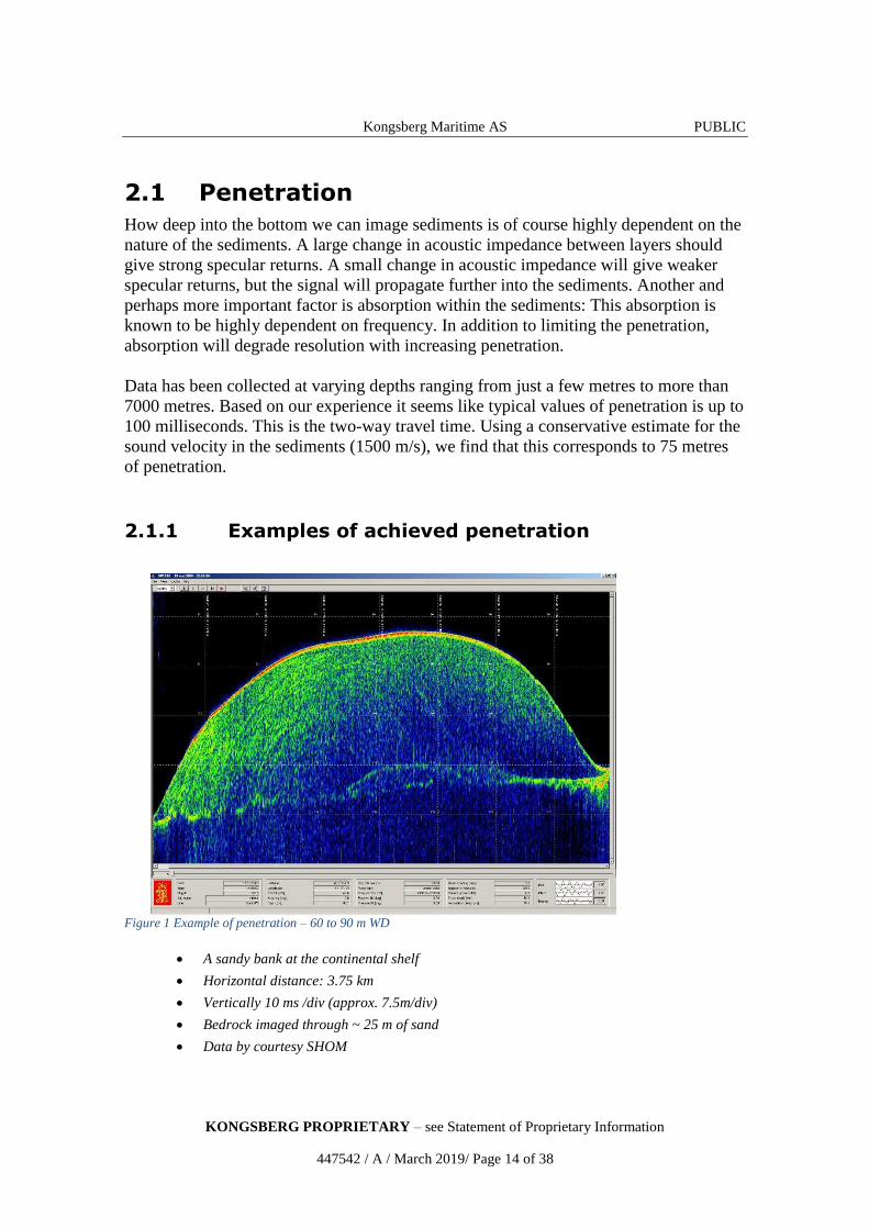
2.1.1 Examples of achieved penetration
Figure 1 Example of penetration – 60 to 90 m WD
A sandy bank at the continental shelf
Horizontal distance: 3.75 km
Vertically 10 ms /div (approx. 7.5m/div)
Bedrock imaged through ~ 25 m of sand
Data by courtesy SHOM
Kongsberg Maritime AS PUBLIC
KONGSBERG PROPRIETARY – see Statement of Proprietary Information
447542 / A / March 2019/ Page 15 of 38
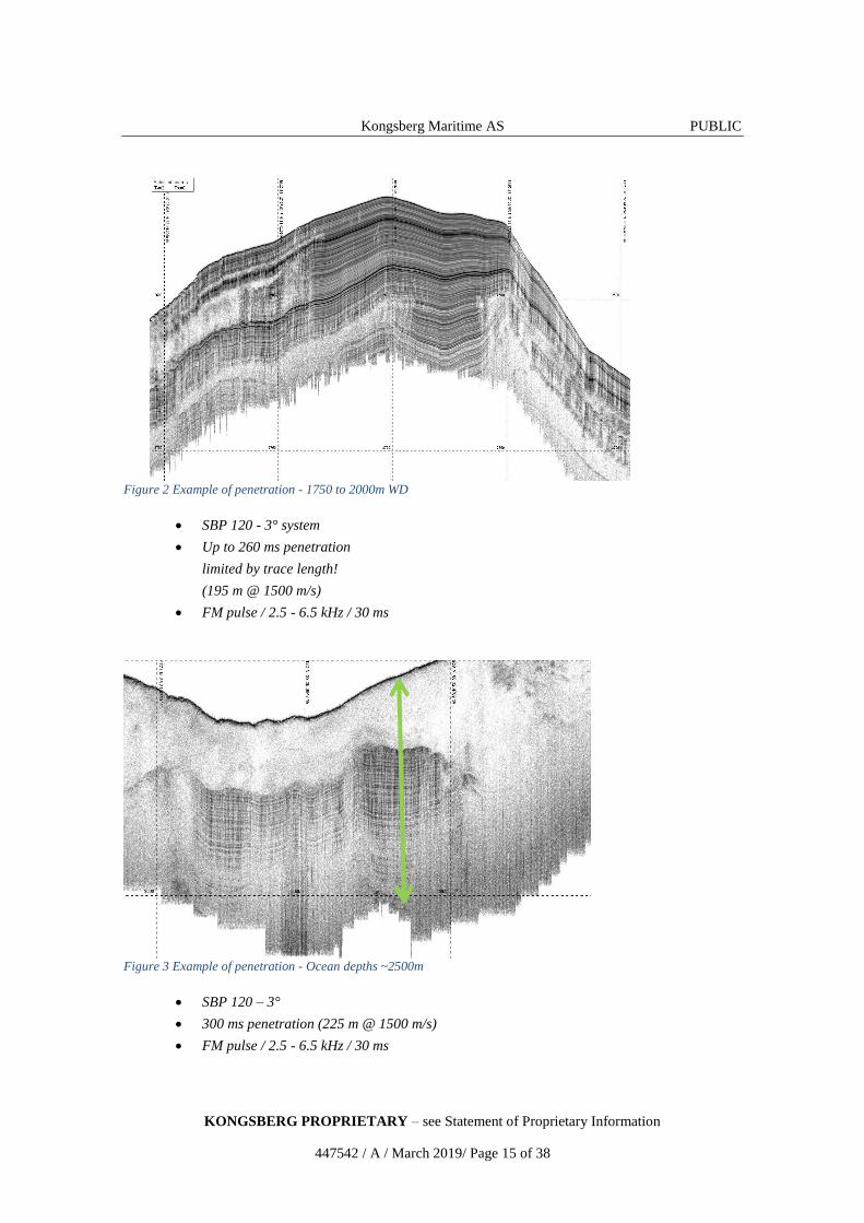
Figure 2 Example of penetration - 1750 to 2000m WD
SBP 120 - 3° system
Up to 260 ms penetration
limited by trace length!
(195 m @ 1500 m/s)
FM pulse / 2.5 - 6.5 kHz / 30 ms
Figure 3 Example of penetration - Ocean depths ~2500m
SBP 120 – 3°
300 ms penetration (225 m @ 1500 m/s)
FM pulse / 2.5 - 6.5 kHz / 30 ms
Kongsberg Maritime AS PUBLIC
KONGSBERG PROPRIETARY – see Statement of Proprietary Information
447542 / A / March 2019/ Page 16 of 38
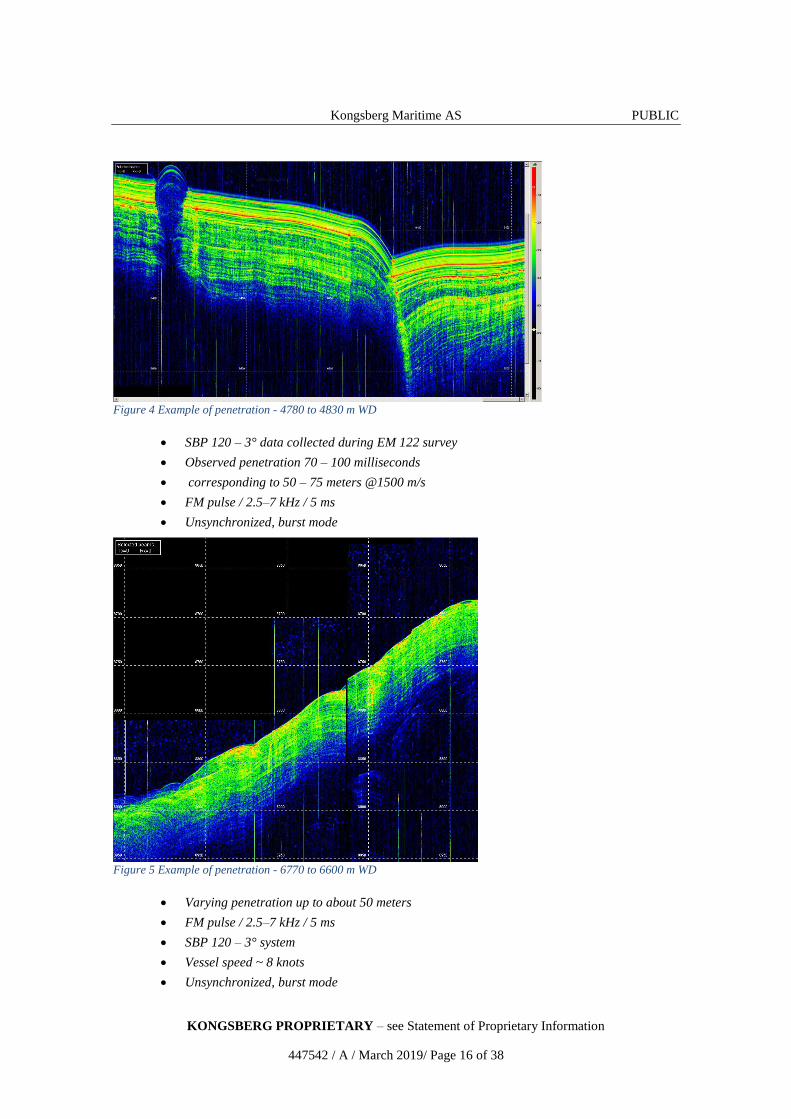
Figure 4 Example of penetration - 4780 to 4830 m WD
SBP 120 – 3° data collected during EM 122 survey
Observed penetration 70 – 100 milliseconds
corresponding to 50 – 75 meters @1500 m/s
FM pulse / 2.5–7 kHz / 5 ms
Unsynchronized, burst mode
Figure 5 Example of penetration - 6770 to 6600 m WD
Varying penetration up to about 50 meters
FM pulse / 2.5–7 kHz / 5 ms
SBP 120 – 3° system
Vessel speed ~ 8 knots
Unsynchronized, burst mode
Kongsberg Maritime AS PUBLIC
KONGSBERG PROPRIETARY – see Statement of Proprietary Information
447542 / A / March 2019/ Page 17 of 38
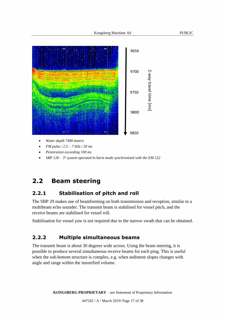
Water depth 7400 meters
FM pulse / 2.5 – 7 kHz / 20 ms
Penetration exceeding 100 ms
SBP 120 – 3° system operated in burst mode synchronized with the EM 122
2.2 Beam steering
2.2.1 Stabilisation of pitch and roll
The SBP 29 makes use of beamforming on both transmission and reception, similar to a
multibeam echo sounder. The transmit beam is stabilised for vessel pitch, and the
receive beams are stabilised for vessel roll.
Stabilisation for vessel yaw is not required due to the narrow swath that can be obtained.
2.2.2 Multiple simultaneous beams
The transmit beam is about 30 degrees wide across. Using the beam steering, it is
possible to produce several simultaneous receive beams for each ping. This is useful
when the sub-bottom structure is complex, e.g. when sediment slopes changes with
angle and range within the insonified volume.
9650
9750
9700
9800
9850
Kongsberg Maritime AS PUBLIC
KONGSBERG PROPRIETARY – see Statement of Proprietary Information
447542 / A / March 2019/ Page 18 of 38
For detection of buried objects, the fan of receiver beams will, compared to wide-beam
sub-bottom profiler systems, provide angular information about the position of the
buried objects. The likelihood of detection will in general be better in a narrow beam.
The narrower the beam and the less the level of reverberation, the easier it will be to
detect an echo from a weak target. Also, if an object buried in sediments is detected in a
narrow beam with oblique incidence to the sediments, the SBP 29 echo from the buried
object will not have to compete with strong specular returns from the sediments, as it
would in a wide beam system.
The SBP 29 offers up to five beams to each side of the centre beam, with selectable
beam spacing, giving a total of up to 11 beams. Maximum receiver fan width is 30
degrees, matching the across transmit beam width.
2.2.3 Active beam steering in sloping terrain
When the EM 124/304 Multibeam echo sounder is used in combination with the SBP
29, estimates of the local seabed inclination angles of the terrain fore-and-aft and across
are obtained in near real-time.
The SBP 29 allows you to steer the transmit beam and the centre of the fan of receive
beams in the direction where they are perpendicular to the underwater terrain. In this
way, the strength of the specular returns is maximised when the sediment layers are
parallel to the seafloor. This maximises the specular return to backscatter ratio.
Beam steering on transmission is limited to compensate for maximum ±10 degrees of
slope fore-and-aft, while beam steering on reception is limited to compensate for
maximum ±10 degrees of slope across. The slope angles are estimated by the EM
124/304 by a least square fit of data to a plane. A few pings and beams within ±10
degrees measured from the vertical are used. The information about slope angles is
transmitted from the EM 124/304 Operator Station over Ethernet.
Kongsberg Maritime AS PUBLIC
KONGSBERG PROPRIETARY – see Statement of Proprietary Information
447542 / A / March 2019/ Page 19 of 38
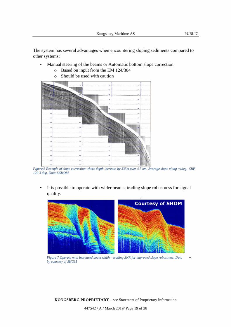
The system has several advantages when encountering sloping sediments compared to
other systems:
• Manual steering of the beams or Automatic bottom slope correction
o Based on input from the EM 124/304
o Should be used with caution
Figure 6 Example of slope correction where depth increase by 335m over 4.5 km. Average slope along ~4deg. SBP
120 3 deg. Data ©SHOM
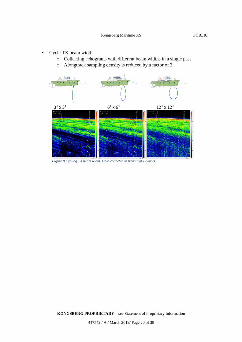
• It is possible to operate with wider beams, trading slope robustness for signal
quality.
•
Courtesy of SHOM
Figure 7 Operate with increased beam width – trading SNR for improved slope robustness. Data
by courtesy of SHOM
Kongsberg Maritime AS PUBLIC
KONGSBERG PROPRIETARY – see Statement of Proprietary Information
447542 / A / March 2019/ Page 20 of 38
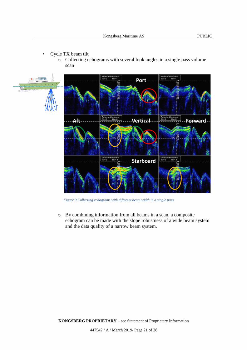
• Cycle TX beam width
o Collecting echograms with different beam widths in a single pass
o Alongtrack sampling density is reduced by a factor of 3
3° x 3° 6° x 6° 12° x 12°
Figure 8 Cycling TX beam width. Data collected in transit @ 12 knots
Kongsberg Maritime AS PUBLIC
KONGSBERG PROPRIETARY – see Statement of Proprietary Information
447542 / A / March 2019/ Page 21 of 38
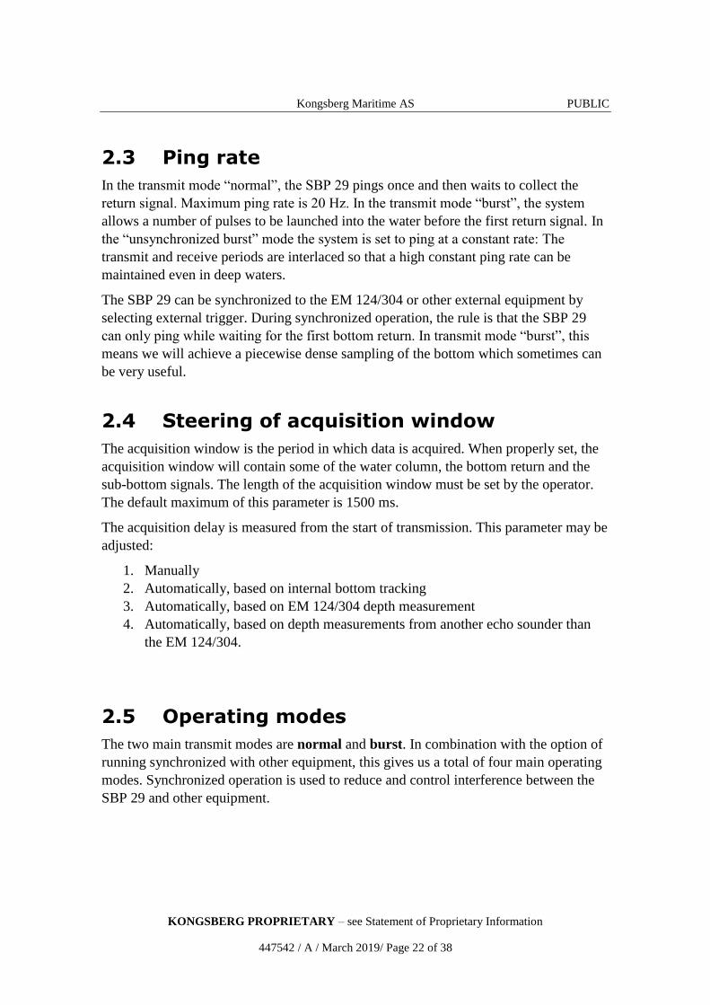
• Cycle TX beam tilt
o Collecting echograms with several look angles in a single pass volume
scan
o By combining information from all beams in a scan, a composite
echogram can be made with the slope robustness of a wide beam system
and the data quality of a narrow beam system.
Figure 9 Collecting echograms with different beam width in a single pass
Starboard
Port
Aft Forward Vertical
Kongsberg Maritime AS PUBLIC
KONGSBERG PROPRIETARY – see Statement of Proprietary Information
447542 / A / March 2019/ Page 22 of 38
2.3 Ping rate
In the transmit mode “normal”, the SBP 29 pings once and then waits to collect the
return signal. Maximum ping rate is 20 Hz. In the transmit mode “burst”, the system
allows a number of pulses to be launched into the water before the first return signal. In
the “unsynchronized burst” mode the system is set to ping at a constant rate: The
transmit and receive periods are interlaced so that a high constant ping rate can be
maintained even in deep waters.
The SBP 29 can be synchronized to the EM 124/304 or other external equipment by
selecting external trigger. During synchronized operation, the rule is that the SBP 29
can only ping while waiting for the first bottom return. In transmit mode “burst”, this
means we will achieve a piecewise dense sampling of the bottom which sometimes can
be very useful.
2.4 Steering of acquisition window
The acquisition window is the period in which data is acquired. When properly set, the
acquisition window will contain some of the water column, the bottom return and the
sub-bottom signals. The length of the acquisition window must be set by the operator.
The default maximum of this parameter is 1500 ms.
The acquisition delay is measured from the start of transmission. This parameter may be
adjusted:
1. Manually
2. Automatically, based on internal bottom tracking
3. Automatically, based on EM 124/304 depth measurement
4. Automatically, based on depth measurements from another echo sounder than
the EM 124/304.
2.5 Operating modes
The two main transmit modes are normal and burst. In combination with the option of
running synchronized with other equipment, this gives us a total of four main operating
modes. Synchronized operation is used to reduce and control interference between the
SBP 29 and other equipment.
Kongsberg Maritime AS PUBLIC
KONGSBERG PROPRIETARY – see Statement of Proprietary Information
447542 / A / March 2019/ Page 23 of 38
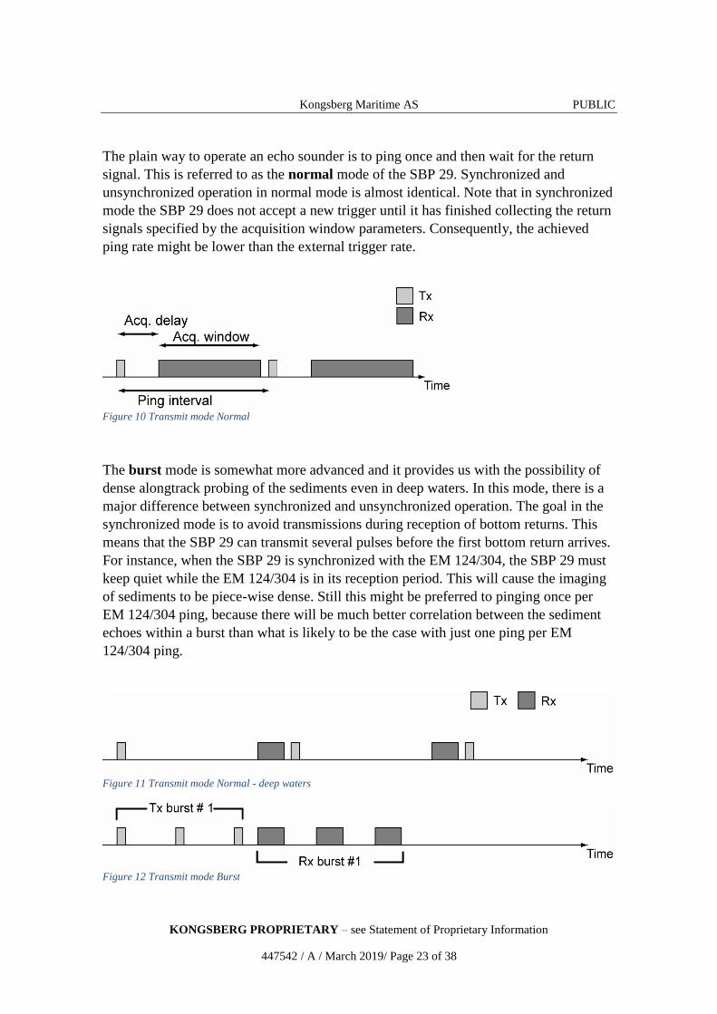
The plain way to operate an echo sounder is to ping once and then wait for the return
signal. This is referred to as the normal mode of the SBP 29. Synchronized and
unsynchronized operation in normal mode is almost identical. Note that in synchronized
mode the SBP 29 does not accept a new trigger until it has finished collecting the return
signals specified by the acquisition window parameters. Consequently, the achieved
ping rate might be lower than the external trigger rate.
Figure 10 Transmit mode Normal
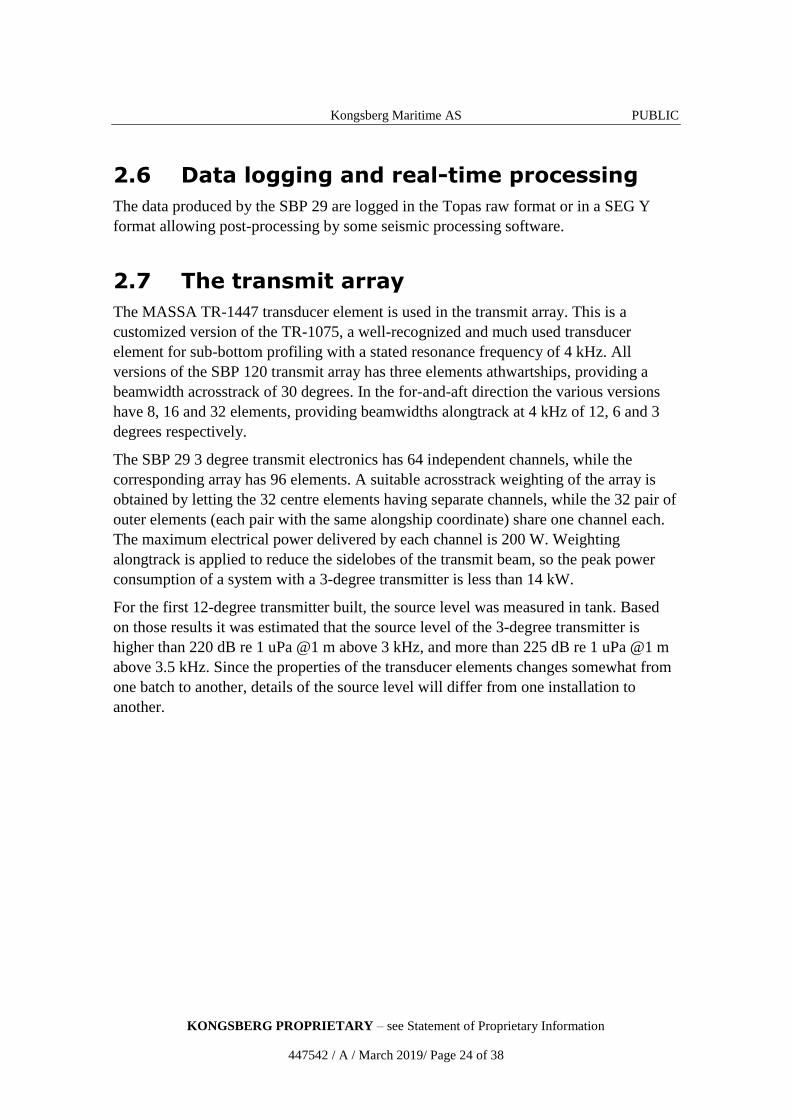
The burst mode is somewhat more advanced and it provides us with the possibility of
dense alongtrack probing of the sediments even in deep waters. In this mode, there is a
major difference between synchronized and unsynchronized operation. The goal in the
synchronized mode is to avoid transmissions during reception of bottom returns. This
means that the SBP 29 can transmit several pulses before the first bottom return arrives.
For instance, when the SBP 29 is synchronized with the EM 124/304, the SBP 29 must
keep quiet while the EM 124/304 is in its reception period. This will cause the imaging
of sediments to be piece-wise dense. Still this might be preferred to pinging once per
EM 124/304 ping, because there will be much better correlation between the sediment
echoes within a burst than what is likely to be the case with just one ping per EM
124/304 ping.
Figure 11 Transmit mode Normal - deep waters
Figure 12 Transmit mode Burst
Kongsberg Maritime AS PUBLIC
KONGSBERG PROPRIETARY – see Statement of Proprietary Information
447542 / A / March 2019/ Page 24 of 38
2.6 Data logging and real-time processing
The data produced by the SBP 29 are logged in the Topas raw format or in a SEG Y
format allowing post-processing by some seismic processing software.
2.7 The transmit array
The MASSA TR-1447 transducer element is used in the transmit array. This is a
customized version of the TR-1075, a well-recognized and much used transducer
element for sub-bottom profiling with a stated resonance frequency of 4 kHz. All
versions of the SBP 120 transmit array has three elements athwartships, providing a
beamwidth acrosstrack of 30 degrees. In the for-and-aft direction the various versions
have 8, 16 and 32 elements, providing beamwidths alongtrack at 4 kHz of 12, 6 and 3
degrees respectively.
The SBP 29 3 degree transmit electronics has 64 independent channels, while the
corresponding array has 96 elements. A suitable acrosstrack weighting of the array is
obtained by letting the 32 centre elements having separate channels, while the 32 pair of
outer elements (each pair with the same alongship coordinate) share one channel each.
The maximum electrical power delivered by each channel is 200 W. Weighting
alongtrack is applied to reduce the sidelobes of the transmit beam, so the peak power
consumption of a system with a 3-degree transmitter is less than 14 kW.
For the first 12-degree transmitter built, the source level was measured in tank. Based
on those results it was estimated that the source level of the 3-degree transmitter is
higher than 220 dB re 1 uPa @1 m above 3 kHz, and more than 225 dB re 1 uPa @1 m
above 3.5 kHz. Since the properties of the transducer elements changes somewhat from
one batch to another, details of the source level will differ from one installation to
another.
Kongsberg Maritime AS PUBLIC
KONGSBERG PROPRIETARY – see Statement of Proprietary Information
447542 / A / March 2019/ Page 25 of 38
3 Installation
3.1 Operator station
A Windows Work Station desktop computer model.
3.2 K-Rem remote control
The Remote Control Unit is called K-Rem. It is prepared for remote control and
interface to an external synchronization system for four Kongsberg echo sounders:
One Sub-bottom profiler (SBP)
Two EM multibeam echo sounders
One EA single beam echo sounder
It has been designed to provide remote on/off switches with light indication and
interface to a remote synchronizing system. K-Rem contains a terminal block and four
switches with lamps mounted in the front.
3.3 Electronic cabinets
The electronic cabinets are preferably installed close to the transducer arrays to reduce
the amount of cabling. In most cases all units are mounted in the same room, but they
may be moved elsewhere to allow easier access.
3.4 Transducer arrays
The transducer arrays should be mounted in the forward part of the vessel, taking into
account hull shape, potential aeration problems and ease of cable installation.
The frames may either be mounted directly on or recessed into the hull, or within sea
chests. The latter solution may be somewhat more expensive, but will ensure that the
transducers are properly mounted within the tolerances required. A fairing will usually
be added around the transducers to ensure a laminar water flow without any aeration
problems. Ice protection windows may be added if required.
A blister or gondola installation will usually help in avoiding air bubble blockage of the
transducers and may contain additional transducers for other systems.

Kongsberg Maritime AS PUBLIC
KONGSBERG PROPRIETARY – see Statement of Proprietary Information
447542 / A / March 2019/ Page 26 of 38
Figure 13 Transducer array installation example (photo taken prior to mounting of baffle)
3.5 Ice Protection Windows
Two types of acoustic protection windows can be offered with the SBP 29
Light ice class
Ice breaker version
In both cases the protection for the TX array is a reinforced structure which is potted by
a material which is acoustically transparent. For the RX array titanium will be used, but
this is to be supplied with the EM 124/304 system. The difference in strength,
dimensions and cost is however substantial. Unless the vessel is carrying out operations
in significantly ice infested waters, it is recommended not to use any protection on the
outside of the transducer arrays.
Note! All ice protection windows provided by Kongsberg Maritime are pressure
tested and comes with a certificate.
Kongsberg Maritime AS PUBLIC
KONGSBERG PROPRIETARY – see Statement of Proprietary Information
447542 / A / March 2019/ Page 27 of 38
4 Scope of supply
4.1 Standard supply
A basic SBP 29 Sub-bottom profiler delivery includes:
1. Operator Station with 19” rack mounting
2. 24” LCD monitor
3. Cable Connection Units
4. SBP 29 Transducer Array
5. SBP 29 Transceiver Unit
6. Necessary cables and mounting frames in accordance with chosen system size
7. Signal and control cables between cabinets; standard length is 8 m
8. All system software
9. System manuals covering system installation, operation and maintenance
4.2 Optional supply
System options available include:
1. Ice protection windows
2. Non-standard cable lengths between the transducer and the Transceiver Unit
3. Spare parts
4.3 System integration
The SBP 29 system is prepared for integration with other sensors to form a complete
seabed mapping and inspection system.
Kongsberg Maritime will always supply the SBP 29 as a sub-system for integration with
an EM 124 or an EM 304, but we can offer complete system solutions tailored to the
user’s need.
Kongsberg Maritime AS PUBLIC
KONGSBERG PROPRIETARY – see Statement of Proprietary Information
447542 / A / March 2019/ Page 28 of 38
5 Operation
5.1 System control
The SBP 29 is controlled from the Operator Station using a graphical user interface. The
system does not require intensive operator intervention during normal operation, as the
bottom track and observation window can be controlled by the EM 124/304.
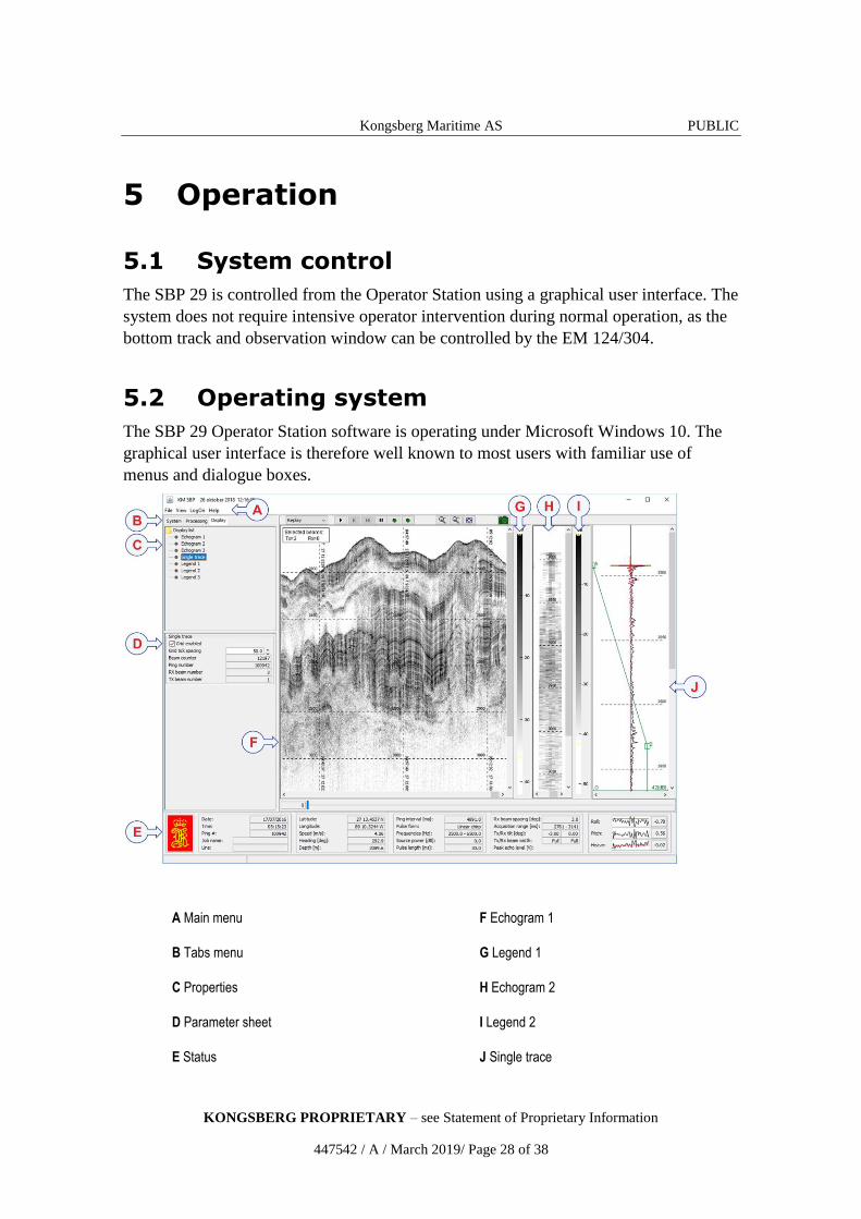
5.2 Operating system
The SBP 29 Operator Station software is operating under Microsoft Windows 10. The
graphical user interface is therefore well known to most users with familiar use of
menus and dialogue boxes.
A Main menu F Echogram 1
B Tabs menu G Legend 1
C Properties H Echogram 2
D Parameter sheet I Legend 2
E Status J Single trace
Kongsberg Maritime AS PUBLIC
KONGSBERG PROPRIETARY – see Statement of Proprietary Information
447542 / A / March 2019/ Page 29 of 38
5.3 Parameter settings
The SBP 29 Operator Station software provides the user with the following system
parameter settings:
• Number of transmit channels
• Number of receiver channels
• Installation angles of the arrays measured in vessel coordinates
• Installation positions of the arrays in vessel coordinates
• Installation position of the motion sensor in vessel coordinates
The following operational parameters may be adjusted:
• Power level
o Pulse form
o Pulse length
o Sweep length
o Start frequency
o Stop frequency
• Transmission mode
• Transmit synchronisation
• Beam width
• Beam steering mode
• Acquisition delay
• Acquisition window length
• Beam spacing and number of receiver beams
Kongsberg Maritime AS PUBLIC
KONGSBERG PROPRIETARY – see Statement of Proprietary Information
447542 / A / March 2019/ Page 30 of 38
6 Technical specifications
Note! Kongsberg Maritime is engaged in continuous developments of its products
and reserves the right to alter specifications without prior notice.
Topics
System performance (3/6/12 deg) on page 30
List of units and sub-units on page 31
Interfaces on page 31
Physical specifications on page 32
Power requirements on page 33
Restriction for use on page 34
Operating and storage temperature on page 34
Surface finish on page 34
Environmental specifications on page 34
Transceiver Unit outline dimensions on page 35
6.1 System performance (3/6/12 deg)
Operating frequency 2 to 9 kHz
Number of beams per ping Maximum 11
Beamwidth, 4 kHz (along x across)
o Transmit 3/6/12 x 35 degrees
o Receive (EM124) 80 x 3/6/12 degrees
o Receive (EM304) 120 x 7/14/28 degrees
Beam spacing ≤ 15 degrees
Fan width (RX) ≤30 degrees
Pulse length (FM and CW) 2 ms to 100 ms
Pulse type FM (linear or hyperbolic), Ricker, CW
Range sampling rate 21.0 kHz
Roll stabilization Yes
Pitch stabilization Yes
Heave compensation Yes
Range resolution 0.2 ms
Volume scanning ± 15 degrees
Maximum penetration >225 m (3 deg system, depending on type
of sediment and noise)
Kongsberg Maritime AS PUBLIC
KONGSBERG PROPRIETARY – see Statement of Proprietary Information
447542 / A / March 2019/ Page 31 of 38
6.2 List of units and sub-units
Operator station
Beamformer Unit
o No physical unit, integrated in the SBP 29 package
Transceiver Unit
Transmit Transducer Array
Remote Control Unit (K-Rem)
o The Remote Control Unit is called K-Rem. It is prepared for remote
control and interface to an external synchronization system for four
Kongsberg echo sounders:
One Sub-bottom profiler (SBP)
Two EM multibeam echo sounders
One EA single beam echo sounder
o It has been designed to provide remote on/off switches with light
indication and interface to a remote synchronizing system. K-Rem
contains a terminal block and four switches with lamps mounted in the
front.
6.3 Interfaces
Operator Station:
Network or serial line interfaces (with operator adjustable baud rate, parity, data length,
and stop bit length) for:
Positions in either Simrad 90, NMEA 0183 GGA and GGK formats.
External clock in NMEA 0183 ZDA format.
Input of depth, bottom slope angles and sound velocity information from EM
124/304 in a native KM datagram format or depth in NMEA DPT format.
Transceiver Unit:
Serial line interface for:
Motion sensor (roll, pitch, heave and optionally heading) in the SIMRAD EM
Attitude format supported by sensors from Applanix, Seatex and TSS.
Digital interfaces for external synchronization:
Trigger inputs (EM and K-Sync)
Trigger output
Ready-to-transmit
Kongsberg Maritime AS PUBLIC
KONGSBERG PROPRIETARY – see Statement of Proprietary Information
447542 / A / March 2019/ Page 32 of 38
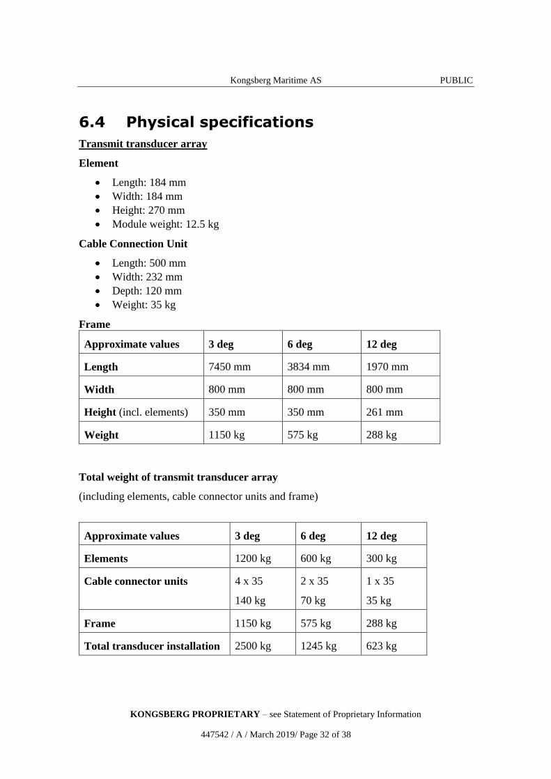
6.4 Physical specifications
Transmit transducer array
Element
Length: 184 mm
Width: 184 mm
Height: 270 mm
Module weight: 12.5 kg
Cable Connection Unit
Length: 500 mm
Width: 232 mm
Depth: 120 mm
Weight: 35 kg
Frame
Approximate values 3 deg 6 deg 12 deg
Length 7450 mm 3834 mm 1970 mm
Width 800 mm 800 mm 800 mm
Height (incl. elements) 350 mm 350 mm 261 mm
Weight 1150 kg 575 kg 288 kg
Total weight of transmit transducer array
(including elements, cable connector units and frame)
Approximate values 3 deg 6 deg 12 deg
Elements 1200 kg 600 kg 300 kg
Cable connector units 4 x 35
140 kg
2 x 35
70 kg
1 x 35
35 kg
Frame 1150 kg 575 kg 288 kg
Total transducer installation 2500 kg 1245 kg 623 kg
Kongsberg Maritime AS PUBLIC
KONGSBERG PROPRIETARY – see Statement of Proprietary Information
447542 / A / March 2019/ Page 33 of 38
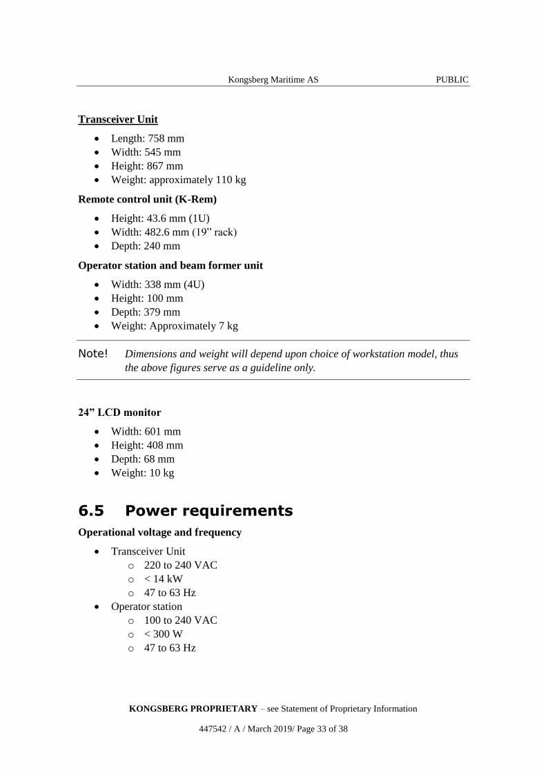
Transceiver Unit
Length: 758 mm
Width: 545 mm
Height: 867 mm
Weight: approximately 110 kg
Remote control unit (K-Rem)
Height: 43.6 mm (1U)
Width: 482.6 mm (19” rack)
Depth: 240 mm
Operator station and beam former unit
Width: 338 mm (4U)
Height: 100 mm
Depth: 379 mm
Weight: Approximately 7 kg
Note! Dimensions and weight will depend upon choice of workstation model, thus
the above figures serve as a guideline only.
24” LCD monitor
Width: 601 mm
Height: 408 mm
Depth: 68 mm
Weight: 10 kg
6.5 Power requirements
Operational voltage and frequency
Transceiver Unit
o 220 to 240 VAC
o < 14 kW
o 47 to 63 Hz
Operator station
o 100 to 240 VAC
o < 300 W
o 47 to 63 Hz
Kongsberg Maritime AS PUBLIC
KONGSBERG PROPRIETARY – see Statement of Proprietary Information
447542 / A / March 2019/ Page 34 of 38
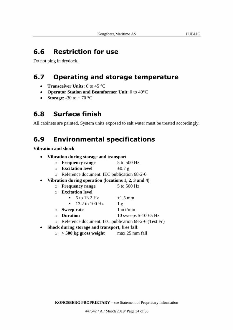
6.6 Restriction for use
Do not ping in drydock.
6.7 Operating and storage temperature
Transceiver Units: 0 to 45 °C
Operator Station and Beamformer Unit: 0 to 40°C
Storage: -30 to + 70 °C
6.8 Surface finish
All cabinets are painted. System units exposed to salt water must be treated accordingly.
6.9 Environmental specifications
Vibration and shock
Vibration during storage and transport
o Frequency range 5 to 500 Hz
o Excitation level ±0.7 g
o Reference document: IEC publication 68-2-6
Vibration during operation (locations 1, 2, 3 and 4)
o Frequency range 5 to 500 Hz
o Excitation level
5 to 13.2 Hz ±1.5 mm
13.2 to 100 Hz 1 g
o Sweep rate 1 oct/min
o Duration 10 sweeps 5-100-5 Hz
o Reference document: IEC publication 68-2-6 (Test Fc)
Shock during storage and transport, free fall:
o > 500 kg gross weight max 25 mm fall

Kongsberg Maritime AS PUBLIC
KONGSBERG PROPRIETARY – see Statement of Proprietary Information
447542 / A / March 2019/ Page 35 of 38
6.10 Transceiver Unit outline dimensions
Kongsberg Maritime AS PUBLIC
KONGSBERG PROPRIETARY – see Statement of Proprietary Information
447542 / A / March 2019/ Page 36 of 38
7 Customer support
Topics
Installation on page 36
Documentation and training on page 36
Service on page 37
FEMME on page 37
Warranty and maintenance contract on page 37
7.1 Installation
As part of the discussions with the client Kongsberg Maritime will - free of charge and
without any obligations - give advice regarding the practical installation of the SBP 29
system. We will also - upon request - prepare proposals for the supply of complete
instrument packages and/or systems. A project manager will usually be appointed to
supervise the delivery, installation and testing of larger instrumentation systems.
The installation and final testing of an SBP 29 system should be done according to
Kongsberg Maritime’s documentation. If required, Kongsberg Maritime field engineers
can be made available to:
Supervise the installation
Perform system check-out and final testing
7.2 Documentation and training
The SBP 29 is delivered with complete documentation for installation, operation and
maintenance. If required, the manuals may optionally be modified to reflect the actual
system on the client’s vessel.
Kongsberg Maritime can conduct the training of operators and maintenance personnel
to the extent required by the client. Such training courses can take place on the vessel,
on any of Kongsberg Maritime’s facilities, or any other location decided by the client.
Kongsberg Maritime AS PUBLIC
KONGSBERG PROPRIETARY – see Statement of Proprietary Information
447542 / A / March 2019/ Page 37 of 38
7.3 Service
The Kongsberg Maritime service department has a 24 hour duty arrangement, and can
thus be contacted by telephone at any time. The service department will assist in solving
all problems that may be encountered during the operation of the system, whether the
problem is caused by finger trouble, insufficient documentation, software bugs or
equipment breakdown.
7.4 FEMME
A forum for users of Kongsberg Maritime’s multibeam echo sounder systems
(FEMME), with the aim of improving communication both between the users and
Kongsberg Maritime, but also between the system users, is arranged at approximately
24 months’ intervals. Close to 100% user participation has been experienced at these
meetings.
7.5 Warranty and maintenance contract
The normal warranty period of the SBP 29 is 24 months after delivery.
A system maintenance contract tailored to fit the needs of the client is available. This
contract can be defined so that it covers repair work only, or complete support for
preventive maintenance, repair work, and system upgrading of both hardware and
software as the system design is improved by Kongsberg Maritime.
The maintenance contract could also include a life-time warranty of transducers,
upgrading of spare parts and documentation, and repeated or additional training courses.
Kongsberg Maritime AS PUBLIC
KONGSBERG PROPRIETARY – see Statement of Proprietary Information
447542 / A / March 2019/ Page 38 of 38
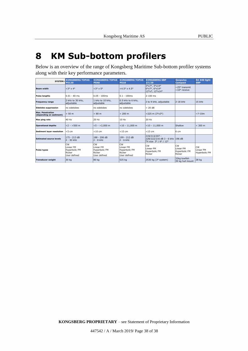
8 KM Sub-bottom profilers Below is an overview of the range of Kongsberg Maritime Sub-bottom profiler systems
along with their key performance parameters.
SYSTEM> KONGSBERG TOPAS
PS120
KONGSBERG TOPAS
PS40
KONGSBERG TOPAS
PS18
KONGSBERG SBP
27/29
Geopulse
Compact
EA 440 light
SBP
Beam width <3° x 4° <3° x 5° <4.5° x 4.5°
3°x7°, 3°x14°
6°x7°, 6°x14°
12°x7, 12°x14°
~25° transmit
~10° receive
Pulse lengths 0.01 - 40 ms 0.05 - 100ms 0.1 - 100ms 2-100 ms
Frequency range 2 kHz to 30 kHz,
adjustable
1 kHz to 10 kHz,
adjustable
0.5 kHz to 6 kHz,
adjustable 2 to 9 kHz, adjustable 2-18 kHz 15 kHz
Sidelobe suppression no sidelobes no sidelobes no sidelobes > 20 dB
Max. Penetration
(depending on sediment)> 50 m > 80 m > 200 m >225 m (3°x3°) ~7-10m
Max ping rate 40 Hz 20 Hz 10 Hz 20 Hz
Operational depths <2 – >500 m <5 – >2,000 m <10 – 11,000 m <10 – 11,000 m Shallow < 300 m
Sediment layer resolution <5 cm <10 cm <15 cm <15 cm 6 cm
Estimated source levels 175 - 213 dB
2 - 30 kHz
188 - 206 dB
2 - 8 kHz
199 - 212 dB
2 - 6 kHz
219/213/207 -
228/222/216 dB 3 - 6 kHz
TX size 3° / 6° / 12°
196 dB
Pulse types
CW
Linear FM
Hyperbolic FM
Ricker
User defined
CW
Linear FM
Hyperbolic FM
Ricker
User defined
CW
Linear FM
Hyperbolic FM
Ricker
User defined
CW
Linear FM
Hyperbolic FM
Ricker
CW
Linear FM
Hyperbolic FM
Ricker
CW
Linear FM
Hyperbolic FM
Transducer weight 30 kg 80 kg 525 kg 2530 kg (3° system)32kg towfish
39 kg hull mount28 kg