Embed Size (px)
Citation preview
Avery-HardollHolland Way
Blandford ForumDorset DT11 7BJ
UK
Tel: +44 (0) 1258 486600Fax: +44 (0) 1258 486601
www.meggittfuelling.com
Whittaker Controls12838 Saticoy StNorth Hollywood
California 91605-3505USA
Tel: +1 818 765 8160Fax: +1 818 759 2194
www.wkr.comwww.meggitt.com
Environmental pit boxGBMY5050 M2 series
The information contained herein is the property of Avery Hardolla division of Meggitt (UK) Ltd. No part may be reproduced orused except as authorised by contract or other writtenpermission. The Company reserves the right to alter withoutnotice the specification, design or conditions of supply of anyproduct or service.
Maintenance manual with spare parts list
Publication ref L005Issue 3 February 2004

TP0002/2
Page (ii)
L005
AMENDMENT RECORD
CHAPTER/PAGE
REASONAMENDMENT/ISSUE NO.
DATE
Page (iii)/(iv)

TP0002/2
Page (iv)
L005
Avery---Hardoll LimitedIt is the aim of Avery---Hardoll Limited to maintain a policy of continuous progress and for this reasonreserve the right to modify specifications without notice. This manual provides the information requiredto install, service and overhaul the equipment. Although every effort has been made to ensure absoluteaccuracy, Avery---Hardoll Limited does not hold itself responsible for any inaccuracies that may befound.
HEALTH AND SAFETY AT WORK ACT 1974
REFERENCE: CHAPTER 37, PART 1, SECTION 6Avery---Hardoll Limited take every care to ensure that, in accordance with the above Act, our products,as far as is reasonably practical in an industrial environment, are when operated and maintained inaccordance with the appropriate manual, safe without risk to health.
PRODUCT SAFETY
In the interest of safety it is strongly recommended by Avery---Hardoll Limited that the following detailsreceive strict attention.
For the Purpose of Definition, the word PRODUCT applies to any product sold by Avery---HardollLimited.
1 The Product is used only with fluids stated as acceptable by Avery---Hardoll Limited.
2 The Product, whilst in service, must not be subjected to pressures greater than the MaximumWorking Pressure or tested to pressures greater than the Test Pressure as specified in the manual.
3 The Product must only be coupled/connected to equipment considered acceptable byAvery---Hardoll Limited.
4 The Product must be handled using the lifting handles where fitted, or in accordance with themanual.
5 The Product must not be misused or handled in any way liable to cause damage.
6 The Product must be inspected for any signs of damage prior to use e.g. cracks, damaged seals,seized or tight operating mechanisms.
7 The Product must be subjected to a regular maintenance programme, either in accordance withthe manual or as agreed with Avery---Hardoll Limited.
8 Only technically competent personnel should repair or maintain the Product and only partssupplied by Avery---Hardoll Limited may be used.
9 Products covered by warranty may not be modified in any way without prior written permission ofAvery---Hardoll Limited.
10 Products not in service, must be stored in a clean area, and should not be subjected to excessivetemperature, humidity, sunlight, or strong artificial light. Products should be protected to preventdamage or the ingress of foreign matter.
11 Where applicable, attention should be drawn to dangers resulting from the generation of staticelectricity in product flow lines. We strongly recommend account is taken of BS5958 parts 1 and 2.
12 This equipment is not suitable for use with Liquid Petroleum Gas (L.P.G).
Page (v)/(vi)

TP0002/2
Page (vi)
L005
WARNINGS
DO NOT HANDLE O-RING SEALS IF THEIR MATERIAL APPEARS CHARRED, GUMMY ORSTICKY. USE TWEEZERS AND WEAR NEOPRENE OR PVC GLOVES. DO NOT TOUCHADJACENT PARTS WITH UNPROTECTED HANDS. NEUTRALIZE ADJACENT PARTS WITHA SOLUTION OF CALCIUM HYDROXIDE. IF THE DEGRADED MATERIAL OR ADJACENTPARTS TOUCH THE SKIN, DO NOT WASH OFF WITH WATER, SEEK IMMEDIATE MEDICALAID FOR POSSIBLE CONTAMINATION WITH HYDROFLUORIC ACID. HYDROFLUORICACID IN CONTACT WITH SKIN HAS DELAYED SYMPTOMS OF CONTAMINATION. IT ISEXTREMELY TOXIC.
DO NOT EXCEED PRESSURES AND TEMPERATURES QUOTED OR SERIOUS INJURY ANDCOMPONENT FAILURE MAY OCCUR.
NO SOLVENTS, CLEANING AGENTS, GREASES OR OTHER MATERIALS ARE TO BEUSED ON INTERNAL SURFACES IN CONTACT WITH FUEL. CLEANING IS TO BECARRIED OUT USING CLEAN AVIATION FUEL ONLY.
WORK MUST BE CARRIED OUT ONLY BY SUITABLY QUALIFIED PERSONNEL.
PRIOR TO COMMENCING WORK, ENSURE THAT ALL AIRPORT/COMPANY SAFETYPROCEDURES HAVE BEEN COMPLIED WITH.
Page (vii)/(viii)

TP0002/2
Page (viii)
L005
CONTENTS
Preliminary material
Title pageAmendment recordHealth and safety at work actProduct safetyWarningsContents and Associated publications (this page)
Chapters
1 Introduction2 Technical description3 Specification4 Installing the Environmental Pit Box5 Inspection, Maintenance and Overhaul6 Spare Parts
ASSOCIATED PUBLICATIONS
Manual No. TP0004 --- UVMY1000 Under Hydrant Valve
Manual No. TP0015 --- PVMY1100 Hydrant Pit Valve
Manual No. TP0035 --- PVMY1000 Hydrant Pit Valve
Manual No. TP0036 --- PVMY2000 Hydrant Pit Valve
Page (ix)/(x)

TP0002/2
Page (ii)
L005
Chap 1Page 1
Chapter 1
INTRODUCTION
CONTENTS
Para1 General2 Application3 Unit Identification
Fig Page1.1 Identification Label 1. . . . . . . . . . . . . . . . . . . . . . . . . . . . . . . . . . . . . . . . . . . . . . . . . . . . . . . . . . . . . . . . . . . . . . . .
1 GENERAL
1.1 With protection of the environment in mind and with the co--operation of one of the majorinternational oil companies, Avery--Hardoll have developed a truly environmentally friendly hydrant pit box.
2 APPLICATION
2.1 Designed specifically to prevent any fuel spillage in the pit from escaping and contaminating thesurrounding area, the two piece construction of the pit provides a large welded inner catchment area withover 0.3 cubic metre capacity below the seal. The design allows for a very large ground movement, 25mm (1”) vertically and 50 mm (2”) horizontally, without affecting valve operation and preventing stress ordamage to the riser pipe.
A high level positive seal fitted between the inner and outer sections of the box ensures that any fuel yousee in the pit is the total spillage and not simply the residue of a larger spillage.
The position of the seal allows ease of inspection and replacement with no requirement for special toolsor hydrant depressurisation.
The lightweight aluminium pit lid is designed to withstand the maximum loads modern aircraft can applywhile still being easily removed for operation.
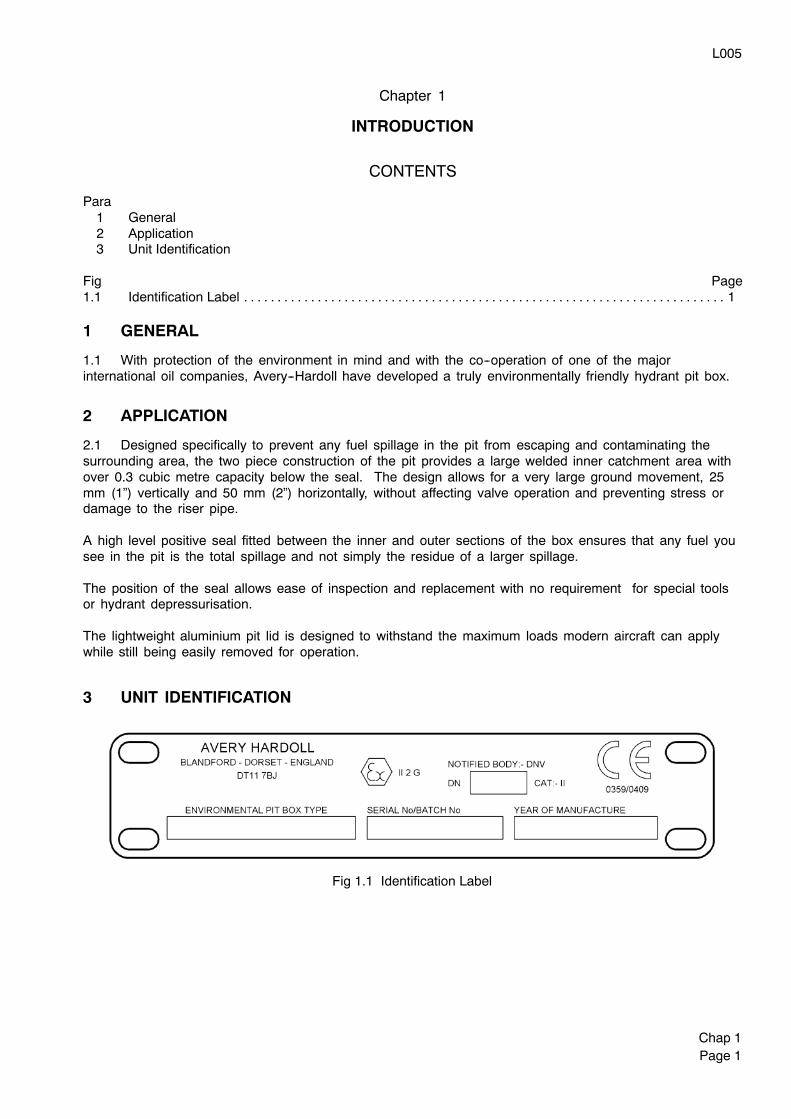
3 UNIT IDENTIFICATION
Fig 1.1 Identification Label

TP0004
Chap 1Page 2
L005
Chap 2Page 1
Chapter 2
TECHNICAL DESCRIPTION
CONTENTS
Para1 Environmental Pit Box
Fig Page2.1 Environmental Pit Box with Under Hydrant Valve and Fuelling Valve 1. . . . . . . . . . . . . . . . . . . . . . . . . . . . .
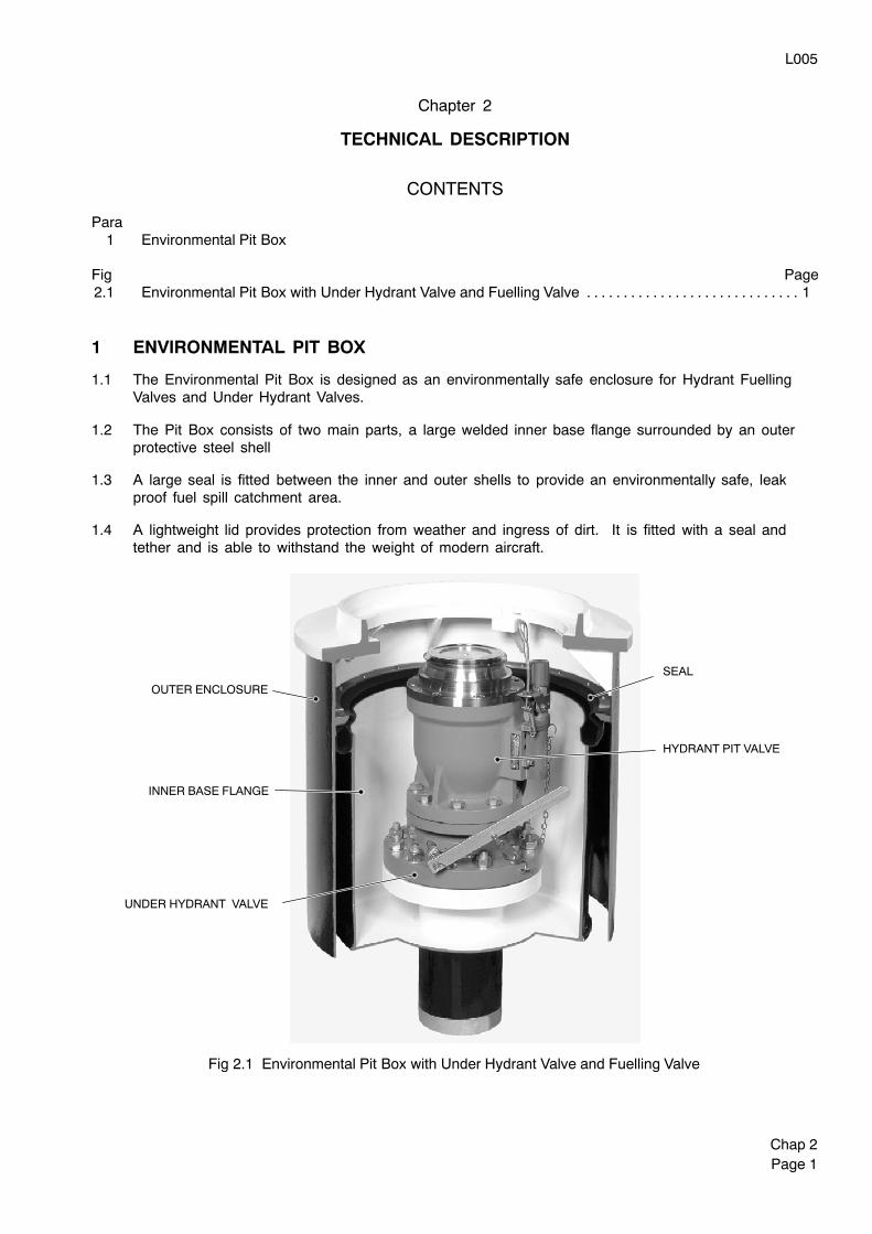
1 ENVIRONMENTAL PIT BOX
1.1 The Environmental Pit Box is designed as an environmentally safe enclosure for Hydrant FuellingValves and Under Hydrant Valves.
1.2 The Pit Box consists of two main parts, a large welded inner base flange surrounded by an outerprotective steel shell
1.3 A large seal is fitted between the inner and outer shells to provide an environmentally safe, leakproof fuel spill catchment area.
1.4 A lightweight lid provides protection from weather and ingress of dirt. It is fitted with a seal andtether and is able to withstand the weight of modern aircraft.
Fig 2.1 Environmental Pit Box with Under Hydrant Valve and Fuelling Valve
UNDER HYDRANT VALVE
HYDRANT PIT VALVE
SEAL
INNER BASE FLANGE
OUTER ENCLOSURE

TP0004
Chap 1Page 2
L005
Chap 3Page 1
Chapter 3
SPECIFICATION
CONTENTS
Para1 Standards2 Materials3 Operating Environment4 Storage Life5 Dimensions and Weight
Fig Page3.1 Dimensions 2. . . . . . . . . . . . . . . . . . . . . . . . . . . . . . . . . . . . . . . . . . . . . . . . . . . . . . . . . . . . . . . . . . . . . . . . . . . . . . .
WARNING
DO NOT EXCEED PRESSURES AND TEMPERATURES QUOTED IN THIS CHAPTER OR SERIOUSINJURY AND COMPONENT FAILURE MAY OCCUR.
1 STANDARDS
1.1 The Environmental Pit Box is built to comply with the following standards:
ATEX ApprovalPED CAT 2
2 MATERIALS
2.1 Components in contact with fuel are manufactured from the following materials:
Main Body Fabrications:Carbon Steel
Environmental Seal:Nitrile Rubber
Lid Seal:Nitrile Rubber
3 OPERATING ENVIRONMENT
3.1 The system into which this equipment is fitted is to be designed to offer the protection fromoverpressurisation and overheating above the working parameters stated below.
3.2 The following units and ancillaries are operational under the following conditions:
Maximum safe working pressure (gauge) 19 bar (275 psi). . . . . . . . . . . . . . . . . . . . . . . . . . . . . . . . . . . . . .Test pressure (gauge) 24 bar (348 psi). . . . . . . . . . . . . . . . . . . . . . . . . . . . . . . . . . . . . . . . . . . . . . . . . . . . . . .Max. working temperature 70 deg C (158 deg F). . . . . . . . . . . . . . . . . . . . . . . . . . . . . . . . . . . . . . . . . . . . . .Min. working temperature -40 deg C (-40 deg F). . . . . . . . . . . . . . . . . . . . . . . . . . . . . . . . . . . . . . . . . . . . . . .
4 STORAGE LIFE
4.1 Storage life of units is 3 years, limited by deterioration of seals and O-rings only.
L005
Chap 3Page 2
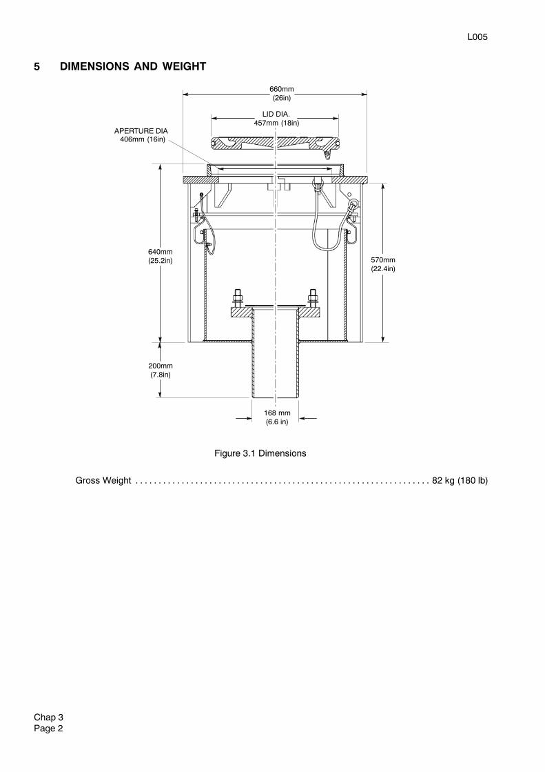
5 DIMENSIONS AND WEIGHT
570mm(22.4in)
Figure 3.1 Dimensions
640mm(25.2in)
APERTURE DIA406mm (16in)
LID DIA.457mm (18in)
660mm(26in)
168 mm(6.6 in)
200mm(7.8in)
Gross Weight 82 kg (180 lb). . . . . . . . . . . . . . . . . . . . . . . . . . . . . . . . . . . . . . . . . . . . . . . . . . . . . . . . . . . . . . . .
L005
Chap 4Page 1
Chapter 4
INSTALLING THE ENVIRONMENTAL PIT BOX
RISER PIPE
GROUND LEVEL
STAGE 1
RISER PIPE
770mm(30.3in)
BASE FLANGESUB--ASSEMBLY
647 mm(25.4in)
STAGE 2
INSTALLATIONSUPPORT
65mm(2.5in)
STAGE 3
POLYSTYRENEBAFFLE
GROUNDBOX ENCLOSURE
FALL AWAY TO DRAINSURFACE AREA 610mm
(24in)
STAGE 4
Installation of Pit Box Assembly
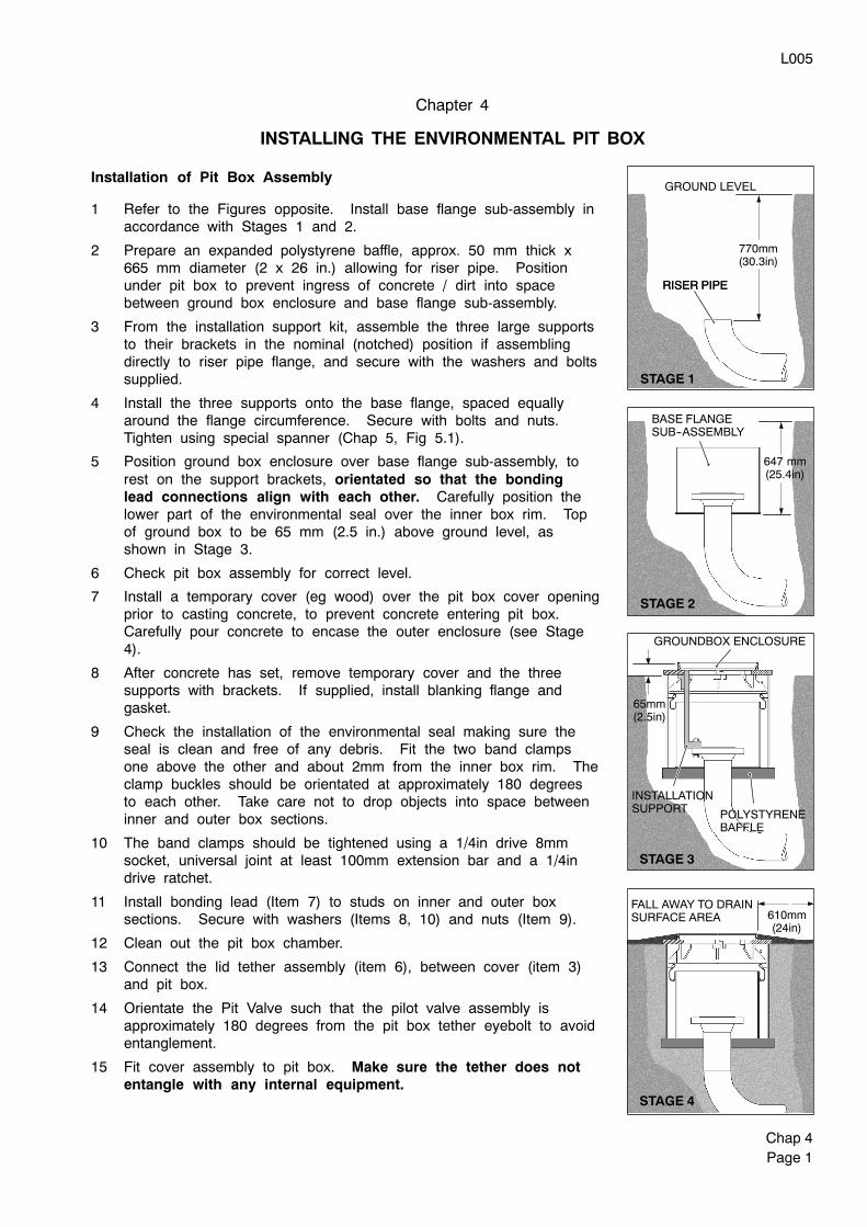
1 Refer to the Figures opposite. Install base flange sub-assembly inaccordance with Stages 1 and 2.
2 Prepare an expanded polystyrene baffle, approx. 50 mm thick x665 mm diameter (2 x 26 in.) allowing for riser pipe. Positionunder pit box to prevent ingress of concrete / dirt into spacebetween ground box enclosure and base flange sub-assembly.
3 From the installation support kit, assemble the three large supportsto their brackets in the nominal (notched) position if assemblingdirectly to riser pipe flange, and secure with the washers and boltssupplied.
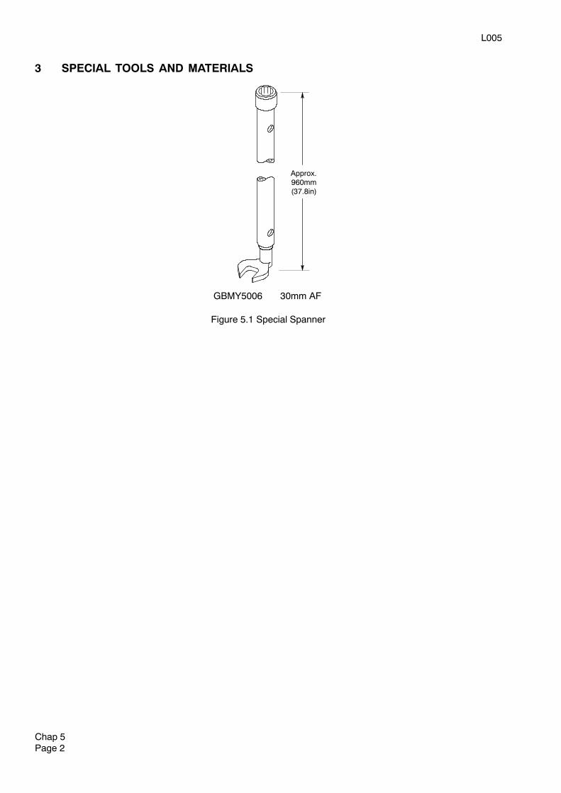
4 Install the three supports onto the base flange, spaced equallyaround the flange circumference. Secure with bolts and nuts.Tighten using special spanner (Chap 5, Fig 5.1).
5 Position ground box enclosure over base flange sub-assembly, torest on the support brackets, orientated so that the bondinglead connections align with each other. Carefully position thelower part of the environmental seal over the inner box rim. Topof ground box to be 65 mm (2.5 in.) above ground level, asshown in Stage 3.
6 Check pit box assembly for correct level.
7 Install a temporary cover (eg wood) over the pit box cover openingprior to casting concrete, to prevent concrete entering pit box.Carefully pour concrete to encase the outer enclosure (see Stage4).
8 After concrete has set, remove temporary cover and the threesupports with brackets. If supplied, install blanking flange andgasket.
9 Check the installation of the environmental seal making sure theseal is clean and free of any debris. Fit the two band clampsone above the other and about 2mm from the inner box rim. Theclamp buckles should be orientated at approximately 180 degreesto each other. Take care not to drop objects into space betweeninner and outer box sections.
10 The band clamps should be tightened using a 1/4in drive 8mmsocket, universal joint at least 100mm extension bar and a 1/4indrive ratchet.
11 Install bonding lead (Item 7) to studs on inner and outer boxsections. Secure with washers (Items 8, 10) and nuts (Item 9).
12 Clean out the pit box chamber.
13 Connect the lid tether assembly (item 6), between cover (item 3)and pit box.
14 Orientate the Pit Valve such that the pilot valve assembly isapproximately 180 degrees from the pit box tether eyebolt to avoidentanglement.
15 Fit cover assembly to pit box. Make sure the tether does notentangle with any internal equipment.

TP0004
Chap 4Page 2
L005
Chap 5Page 1
Chapter 5
INSPECTION, MAINTENANCE AND OVERHAUL
CONTENTS
Para1 General2 Routine Inspection and Maintenance3 Special Tools and Materials
Fig Page5.1 Special Spanner 2. . . . . . . . . . . . . . . . . . . . . . . . . . . . . . . . . . . . . . . . . . . . . . . . . . . . . . . . . . . . . . . . . . . . . . . . . . .
1 GENERAL
WARNING
DO NOT HANDLE O-RING SEALS IF THEIR MATERIAL APPEARS CHARRED, GUMMY ORSTICKY. USE TWEEZERS AND WEAR NEOPRENE OR PVC GLOVES. DO NOT TOUCHADJACENT PARTS WITH UNPROTECTED HANDS. NEUTRALIZE ADJACENT PARTS WITH ASOLUTION OF CALCIUM, HYDROXIDE. IF THE DEGRADED MATERIAL OR ADJACENT PARTSTOUCH THE SKIN, DO NOT WASH OFF WITH WATER, SEEK IMMEDIATE MEDICAL AID FORPOSSIBLE CONTAMINATION WITH HYDROFLUORIC ACID. HYDROFLUORIC ACID IN CONTACTWITH SKIN HAS DELAYED SYMPTOMS OF CONTAMINATION. IT IS EXTREMELY TOXIC.
WORK MUST BE CARRIED OUT ONLY BY SUITABLY QUALIFIED PERSONNEL.
PRIOR TO COMMENCING WORK, ENSURE THAT ALL AIRPORT/COMPANY SAFETYPROCEDURES HAVE BEEN COMPLIED WITH.
1.1 Before dismantling any unit ensure that all special tools, materials and replacement parts areavailable. Only Avery--Hardoll supplied parts and special tools are to be used.
1.2 On completion of overhaul, and during installation, units should be checked for any leakage.
2 ROUTINE INSPECTION AND MAINTENANCE
WARNING
NO SOLVENTS, CLEANING AGENTS, GREASES OR OTHER MATERIALS ARE TO BE USED ONINTERNAL SURFACES IN CONTACT WITH FUEL. CLEANING IS TO BE CARRIED OUT USINGCLEAN AVIATION FUEL ONLY.
2.1 Weekly
Clear the EPB of any residual rain water, fuel and debris and dispose of according to localenvironmental policies.
If rain water is regularly present in the Pit Box, renew the lid seal.
Check integrity of Pit Box lid tether
2.2 Annually
Check integrity of all seals.
Check the Pit Box lid for cracks and any general damage that may affect the secure closing of the lid.If any cracks are detected the lid is to be replaced.
NOTE:
The above maintenance frequencies are the minimum recommended but local companyinstructions must be observed.
All seals to be replaced after a 5 year period.
L005
Chap 5Page 2
3 SPECIAL TOOLS AND MATERIALS
GBMY5006 30mm AF
Approx.960mm(37.8in)
Figure 5.1 Special Spanner
L005
Chap 6Page 1
Chapter 6
SPARE PARTS CATALOGUE
CONTENTS
Para1 General2 Spare parts details
Fig Page6.1 Environmental Pit Box Assembly 2. . . . . . . . . . . . . . . . . . . . . . . . . . . . . . . . . . . . . . . . . . . . . . . . . . . . . . . . . . .
1 GENERAL
1.1 Only parts supplied by Avery--Hardoll are to be used to repair this equipment.
1.2 When ordering spare parts please quote the following information:
(a) Publication number and issue
(b) Fig/Item number
(c) Part number and description
(d) Quantity
2 SPARE PARTS DETAILS
2.1 The following tables of spare parts also contain the relevant attaching parts, i.e. screws, washers,nuts, etc, which may fail as a result of repeated removal and insertion.
NOTES
(1) ‘+’ in the Fig/Item column indicates Item is not illustrated.
(2) ‘REF’ in the Qty column indicates Item is for reference purposes only andis not available as a spare.
(3) ‘*’ in the Fig/Item column indicates Item is recommended as a spare part
L005
Chap 6Page 2
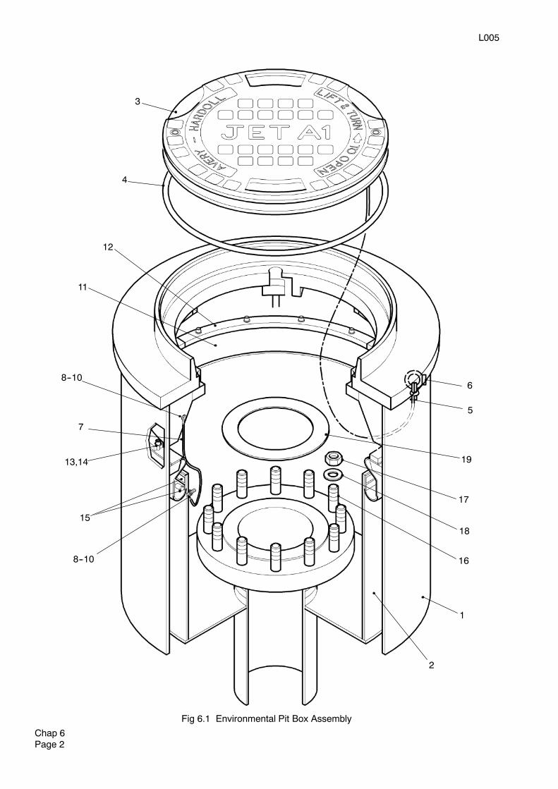
Fig 6.1 Environmental Pit Box Assembly
3
4
12
11
8--10
7
13,14
15
8--10
2
1
6
5
17
18
16
19
L005
Chap 6Page 3
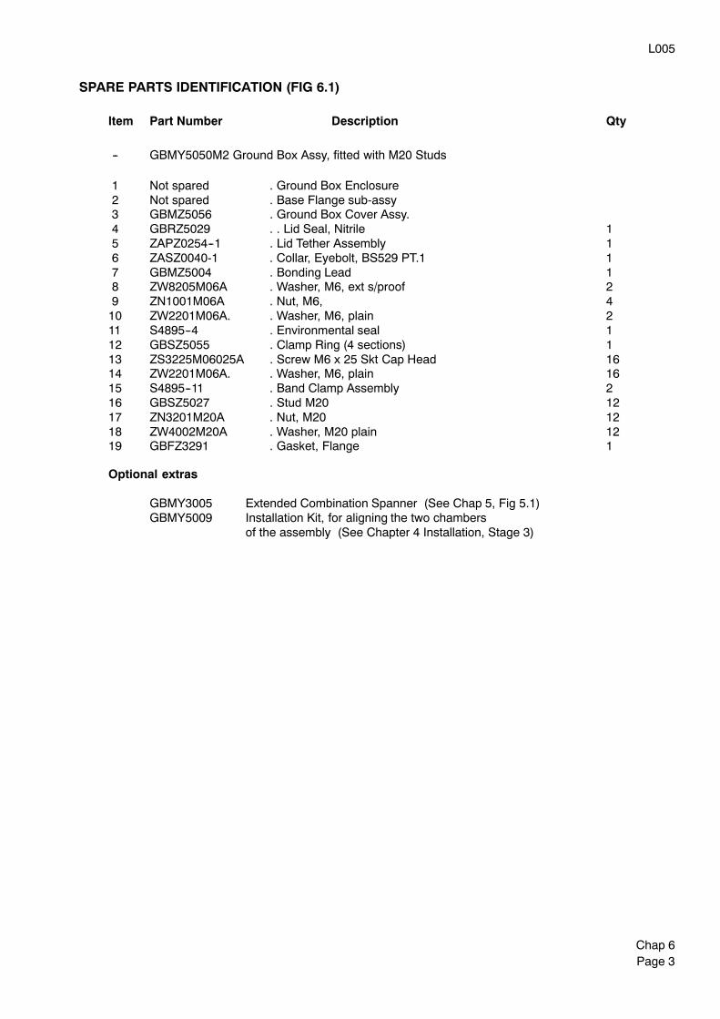
SPARE PARTS IDENTIFICATION (FIG 6.1)
Item Part Number Description Qty
-- GBMY5050M2 Ground Box Assy, fitted with M20 Studs
1 Not spared . Ground Box Enclosure2 Not spared . Base Flange sub-assy3 GBMZ5056 . Ground Box Cover Assy.4 GBRZ5029 . . Lid Seal, Nitrile 15 ZAPZ0254--1 . Lid Tether Assembly 16 ZASZ0040-1 . Collar, Eyebolt, BS529 PT.1 17 GBMZ5004 . Bonding Lead 18 ZW8205M06A . Washer, M6, ext s/proof 29 ZN1001M06A . Nut, M6, 410 ZW2201M06A. . Washer, M6, plain 211 S4895--4 . Environmental seal 112 GBSZ5055 . Clamp Ring (4 sections) 113 ZS3225M06025A . Screw M6 x 25 Skt Cap Head 1614 ZW2201M06A. . Washer, M6, plain 1615 S4895--11 . Band Clamp Assembly 216 GBSZ5027 . Stud M20 1217 ZN3201M20A . Nut, M20 1218 ZW4002M20A . Washer, M20 plain 1219 GBFZ3291 . Gasket, Flange 1
Optional extras
GBMY3005 Extended Combination Spanner (See Chap 5, Fig 5.1)GBMY5009 Installation Kit, for aligning the two chambers
of the assembly (See Chapter 4 Installation, Stage 3)

L005
Chap 6Page 4