Embed Size (px)
Citation preview
19
Modified from P. Laws, D. Sokoloff, R. Thornton Supported by National Science Foundation
and the U.S. Dept. of Education (FIPSE), 1993-2000
University of Virginia Physics Department PHYS 241W, Fall 2004
Name ___________________________ Date ____________ Partners__________________________________
Lab 2-SIMPLE DC CIRCUITS
OBJECTIVES
• To understand how a potential difference (voltage) can cause an electric current through a conductor.
• To learn to design and construct simple circuits using batteries, bulbs, wires, and switches.
• To learn to draw circuit diagrams using symbols. • To understand currents at all points in simple circuits. • To understand the meaning of series and parallel connections in an
electric circuit.
OVERVIEW
In the following labs, you are going to discover and extend theories about electric charge and potential difference (voltage), and apply them to electric circuits. A battery is a device that generates an electric potential difference (voltage) from other forms of energy. The type of batteries you will use in these labs are known as chemical batteries because they convert internal chemical energy into electrical energy. As a result of a potential difference, electric charge is repelled from one terminal of the battery and attracted to the other. However, no charge can flow out of a battery unless there is a conducting material connected between its terminals. If this conductor happens to be the filament in a small light bulb, the flow of charge will cause the light bulb to glow. In this lab, you are going to explore how charge flows in wires and bulbs when energy has been transferred to it by a battery. You will be asked to develop and explain some models that predict how the charge flows. You will also be asked to devise ways to test your models using current and voltage probes which can measure the rate of flow of
20 Lab 2 - Batteries, Bulbs, and Currents in Simple DC Circuits
Modified from P. Laws, D. Sokoloff, R. Thornton Supported by National Science Foundation
and US Department of Education (FIPSE), 1993-2000
University of Virginia Physics Department PHYS 241W, Fall 2004
electric charge and the potential difference (voltage), respectively, and display these quantities on a computer screen. Then you will examine more complicated circuits than a single bulb connected to a single battery. You will compare the currents through different parts of these circuits by comparing the brightness of the bulbs, and also by measuring the currents using current probes. *Some of the activities in this lab have been adapted from those designed by the Physics Education Group at the University of Washington.
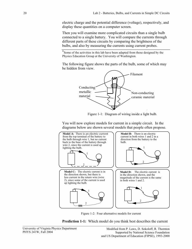
The following figure shows the parts of the bulb, some of which may be hidden from view.
Non-conducting ceramic material
Figure 1-1: Diagram of wiring inside a light bulb.
Conducting metallic material
Filament
You will now explore models for current in a simple circuit. In the diagrams below are shown several models that people often propose.
Model A: There is an electric current from the top terminal of the battery to the bulb through wire 1, but no current back to the base of the battery through wire 2, since the current is used up lighting the bulb.
Model B: There is an electric current in both wires 1 and 2 in a direction from the battery to the bulb.
1
2
Model C: The electric current is in the direction shown, but there is less current in the return wire (wire 2), since some of the current is used up lighting the bulb.
2
1
1
2
Model D: The electric current is in the direction shown, and the magnitude of the current is the same in both wires 1 and 2.
1
2
Figure 1-2: Four alternative models for current
Prediction 1-1: Which model do you think best describes the current
Lab 2 - Batteries, Bulbs, and Currents in Simple DC Circuits 21
Modified from P. Laws, D. Sokoloff, R. Thornton Supported by National Science Foundation
and the U.S. Dept. of Education (FIPSE), 1993-2000
University of Virginia Physics Department PHYS 241W, Fall 2004
through the bulb? Explain your reasoning.
For the Investigations in this lab, you will need the following:
• two current probes • two voltage probes • D cell battery • 2 resistors (~82 Ω) • push (contact) switch • knife switch • battery holder • 8 wires with alligator clips • 3 bulbs (#14) and holders
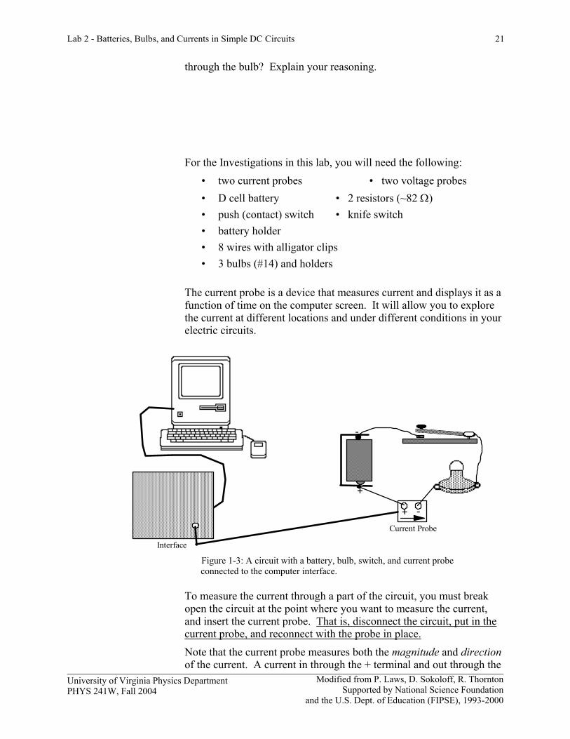
The current probe is a device that measures current and displays it as a function of time on the computer screen. It will allow you to explore the current at different locations and under different conditions in your electric circuits.
+ - Current Probe
-
+
Interface Figure 1-3: A circuit with a battery, bulb, switch, and current probe connected to the computer interface.
To measure the current through a part of the circuit, you must break open the circuit at the point where you want to measure the current, and insert the current probe. That is, disconnect the circuit, put in the current probe, and reconnect with the probe in place. Note that the current probe measures both the magnitude and direction of the current. A current in through the + terminal and out through the
22 Lab 2 - Batteries, Bulbs, and Currents in Simple DC Circuits
Modified from P. Laws, D. Sokoloff, R. Thornton Supported by National Science Foundation
and US Department of Education (FIPSE), 1993-2000
University of Virginia Physics Department PHYS 241W, Fall 2004
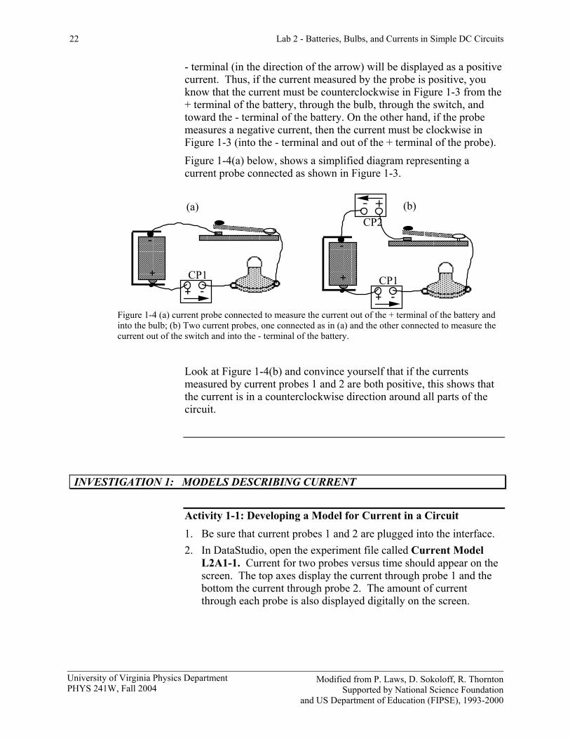
- terminal (in the direction of the arrow) will be displayed as a positive current. Thus, if the current measured by the probe is positive, you know that the current must be counterclockwise in Figure 1-3 from the + terminal of the battery, through the bulb, through the switch, and toward the - terminal of the battery. On the other hand, if the probe measures a negative current, then the current must be clockwise in Figure 1-3 (into the - terminal and out of the + terminal of the probe). Figure 1-4(a) below, shows a simplified diagram representing a current probe connected as shown in Figure 1-3.
CP2
CP1 + -
CP1+ -
(a) (b)
+ +
- -
Figure 1-4 (a) current probe connected to measure the current out of the + terminal of the battery and into the bulb; (b) Two current probes, one connected as in (a) and the other connected to measure the current out of the switch and into the - terminal of the battery.
Look at Figure 1-4(b) and convince yourself that if the currents measured by current probes 1 and 2 are both positive, this shows that the current is in a counterclockwise direction around all parts of the circuit.
INVESTIGATION 1: MODELS DESCRIBING CURRENT
Activity 1-1: Developing a Model for Current in a Circuit 1. Be sure that current probes 1 and 2 are plugged into the interface. 2. In DataStudio, open the experiment file called Current Model
L2A1-1. Current for two probes versus time should appear on the screen. The top axes display the current through probe 1 and the bottom the current through probe 2. The amount of current through each probe is also displayed digitally on the screen.
Lab 2 - Batteries, Bulbs, and Currents in Simple DC Circuits 23
Modified from P. Laws, D. Sokoloff, R. Thornton Supported by National Science Foundation
and the U.S. Dept. of Education (FIPSE), 1993-2000
University of Virginia Physics Department PHYS 241W, Fall 2004
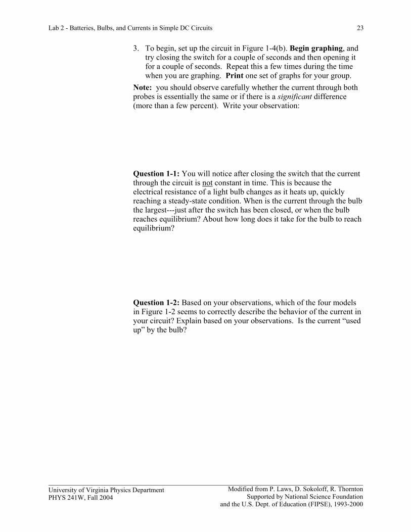
3. To begin, set up the circuit in Figure 1-4(b). Begin graphing, and try closing the switch for a couple of seconds and then opening it for a couple of seconds. Repeat this a few times during the time when you are graphing. Print one set of graphs for your group.
Note: you should observe carefully whether the current through both probes is essentially the same or if there is a significant difference (more than a few percent). Write your observation:
Question 1-1: You will notice after closing the switch that the current through the circuit is not constant in time. This is because the electrical resistance of a light bulb changes as it heats up, quickly reaching a steady-state condition. When is the current through the bulb the largest---just after the switch has been closed, or when the bulb reaches equilibrium? About how long does it take for the bulb to reach equilibrium? Question 1-2: Based on your observations, which of the four models in Figure 1-2 seems to correctly describe the behavior of the current in your circuit? Explain based on your observations. Is the current “used up” by the bulb?
24 Lab 2 - Batteries, Bulbs, and Currents in Simple DC Circuits
Modified from P. Laws, D. Sokoloff, R. Thornton Supported by National Science Foundation
and US Department of Education (FIPSE), 1993-2000
University of Virginia Physics Department PHYS 241W, Fall 2004
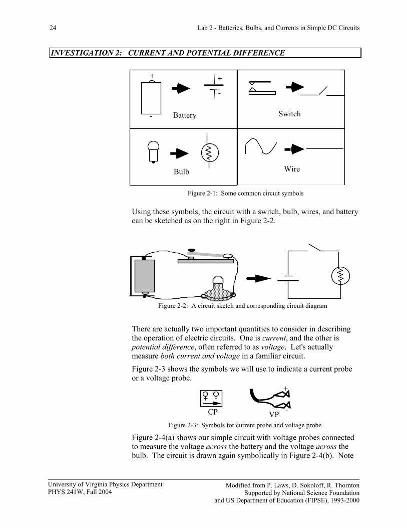
INVESTIGATION 2: CURRENT AND POTENTIAL DIFFERENCE
Switch
Bulb Wire
Battery
+
-
+
-
Figure 2-1: Some common circuit symbols
Using these symbols, the circuit with a switch, bulb, wires, and battery can be sketched as on the right in Figure 2-2.
Figure 2-2: A circuit sketch and corresponding circuit diagram
There are actually two important quantities to consider in describing the operation of electric circuits. One is current, and the other is potential difference, often referred to as voltage. Let's actually measure both current and voltage in a familiar circuit. Figure 2-3 shows the symbols we will use to indicate a current probe or a voltage probe.
+ -
CP
+
- VP Figure 2-3: Symbols for current probe and voltage probe.
Figure 2-4(a) shows our simple circuit with voltage probes connected to measure the voltage across the battery and the voltage across the bulb. The circuit is drawn again symbolically in Figure 2-4(b). Note
Lab 2 - Batteries, Bulbs, and Currents in Simple DC Circuits 25
Modified from P. Laws, D. Sokoloff, R. Thornton Supported by National Science Foundation
and the U.S. Dept. of Education (FIPSE), 1993-2000
University of Virginia Physics Department PHYS 241W, Fall 2004
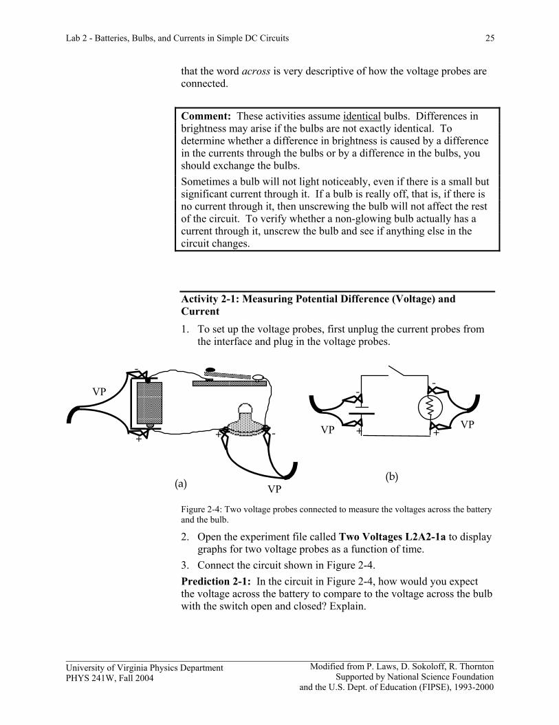
that the word across is very descriptive of how the voltage probes are connected. Comment: These activities assume identical bulbs. Differences in brightness may arise if the bulbs are not exactly identical. To determine whether a difference in brightness is caused by a difference in the currents through the bulbs or by a difference in the bulbs, you should exchange the bulbs. Sometimes a bulb will not light noticeably, even if there is a small but significant current through it. If a bulb is really off, that is, if there is no current through it, then unscrewing the bulb will not affect the rest of the circuit. To verify whether a non-glowing bulb actually has a current through it, unscrew the bulb and see if anything else in the circuit changes.
Activity 2-1: Measuring Potential Difference (Voltage) and Current 1. To set up the voltage probes, first unplug the current probes from
the interface and plug in the voltage probes.
+
-
VP +
-
VP+
-
VP
+ -
VP(a) (a) (b)
Figure 2-4: Two voltage probes connected to measure the voltages across the battery and the bulb. 2. Open the experiment file called Two Voltages L2A2-1a to display
graphs for two voltage probes as a function of time. 3. Connect the circuit shown in Figure 2-4. Prediction 2-1: In the circuit in Figure 2-4, how would you expect the voltage across the battery to compare to the voltage across the bulb with the switch open and closed? Explain.
26 Lab 2 - Batteries, Bulbs, and Currents in Simple DC Circuits
Modified from P. Laws, D. Sokoloff, R. Thornton Supported by National Science Foundation
and US Department of Education (FIPSE), 1993-2000
University of Virginia Physics Department PHYS 241W, Fall 2004
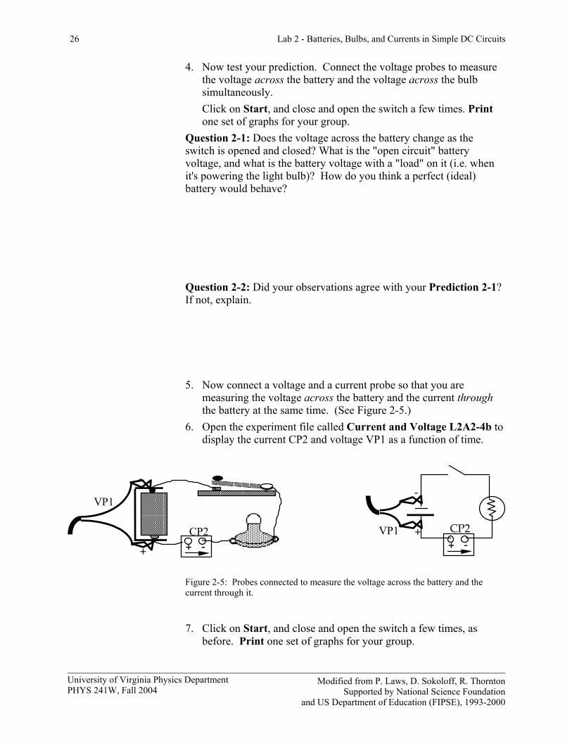
4. Now test your prediction. Connect the voltage probes to measure the voltage across the battery and the voltage across the bulb simultaneously. Click on Start, and close and open the switch a few times. Print one set of graphs for your group.
Question 2-1: Does the voltage across the battery change as the switch is opened and closed? What is the "open circuit" battery voltage, and what is the battery voltage with a "load" on it (i.e. when it's powering the light bulb)? How do you think a perfect (ideal) battery would behave? Question 2-2: Did your observations agree with your Prediction 2-1? If not, explain.
5. Now connect a voltage and a current probe so that you are
measuring the voltage across the battery and the current through the battery at the same time. (See Figure 2-5.)
6. Open the experiment file called Current and Voltage L2A2-4b to display the current CP2 and voltage VP1 as a function of time.
CP2 + - +
-
VP1
+
-
VP1+ -CP2
Figure 2-5: Probes connected to measure the voltage across the battery and the current through it. 7. Click on Start, and close and open the switch a few times, as
before. Print one set of graphs for your group.
Lab 2 - Batteries, Bulbs, and Currents in Simple DC Circuits 27
Modified from P. Laws, D. Sokoloff, R. Thornton Supported by National Science Foundation
and the U.S. Dept. of Education (FIPSE), 1993-2000
University of Virginia Physics Department PHYS 241W, Fall 2004
Question 2-3: Explain the appearance of your current and voltage graphs. What happens to the current through the battery as the switch is closed and opened? What happens to the voltage across the battery? 8. Find the voltage across, and the current through, the battery when
the switch is closed, the bulb is lit, and the values are constant. Use the Smart Tool and/or the Statistics feature.
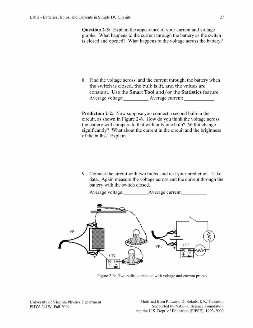
Average voltage:__________ Average current: ____________ Prediction 2-2: Now suppose you connect a second bulb in the circuit, as shown in Figure 2-6. How do you think the voltage across the battery will compare to that with only one bulb? Will it change significantly? What about the current in the circuit and the brightness of the bulbs? Explain. 9. Connect the circuit with two bulbs, and test your prediction. Take
data. Again measure the voltage across and the current through the battery with the switch closed.
Average voltage:__________Average current:__________
VP1
VP1
CP2
CP2
Figure 2-6: Two bulbs connected with voltage and current probes.
28 Lab 2 - Batteries, Bulbs, and Currents in Simple DC Circuits
Modified from P. Laws, D. Sokoloff, R. Thornton Supported by National Science Foundation
and US Department of Education (FIPSE), 1993-2000
University of Virginia Physics Department PHYS 241W, Fall 2004
Question 2-4: Did the current through the battery change significantly when you added the second bulb to the circuit (by more than 5%)?
Question 2-5: Did the voltage across the battery change significantly when you added the second bulb to the circuit (by more than 5%)? Question 2-6: Does the battery appear to be a source of constant current, constant voltage, or neither when different elements are added to a circuit?
INVESTIGATION 3: CURRENT IN SERIES CIRCUITS In the next series of activities you will be asked to make a number of predictions about the current in various circuits, and then to compare your predictions with actual observations. Whenever your experimental observations disagree with your predictions you should try to develop new concepts about how circuits with batteries and bulbs actually work. Hint: Helpful symbols are (> "is greater than", < "is less than", = "is equal to"), for example B>C>A
Prediction 3-1: What would you predict about the relative amount of current going through each bulb in Figures 3-1 (a) and (b)? Write down your predicted order of the amount of current passing through bulbs A, B and C.
Lab 2 - Batteries, Bulbs, and Currents in Simple DC Circuits 29
Modified from P. Laws, D. Sokoloff, R. Thornton Supported by National Science Foundation
and the U.S. Dept. of Education (FIPSE), 1993-2000
University of Virginia Physics Department PHYS 241W, Fall 2004
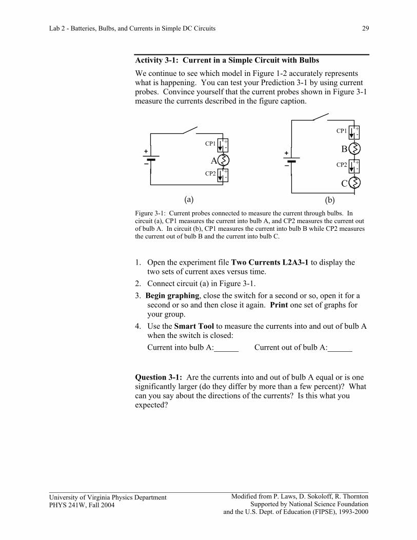
Activity 3-1: Current in a Simple Circuit with Bulbs We continue to see which model in Figure 1-2 accurately represents what is happening. You can test your Prediction 3-1 by using current probes. Convince yourself that the current probes shown in Figure 3-1 measure the currents described in the figure caption.
CP1 -+
CP2 -+
CP1 -+
CP2 -+A
B
C
(a) (b)
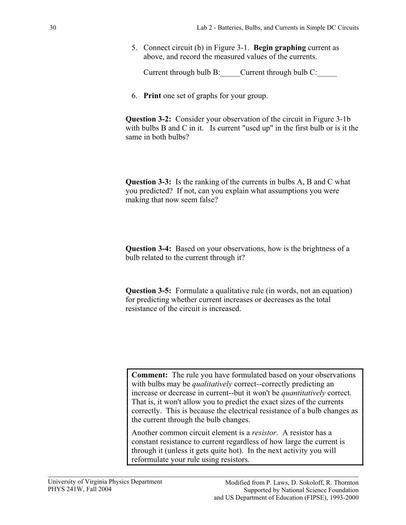
Figure 3-1: Current probes connected to measure the current through bulbs. In circuit (a), CP1 measures the current into bulb A, and CP2 measures the current out of bulb A. In circuit (b), CP1 measures the current into bulb B while CP2 measures the current out of bulb B and the current into bulb C.
1. Open the experiment file Two Currents L2A3-1 to display the
two sets of current axes versus time. 2. Connect circuit (a) in Figure 3-1. 3. Begin graphing, close the switch for a second or so, open it for a
second or so and then close it again. Print one set of graphs for your group.
4. Use the Smart Tool to measure the currents into and out of bulb A when the switch is closed:
Current into bulb A:______ Current out of bulb A:______
Question 3-1: Are the currents into and out of bulb A equal or is one significantly larger (do they differ by more than a few percent)? What can you say about the directions of the currents? Is this what you expected?
30 Lab 2 - Batteries, Bulbs, and Currents in Simple DC Circuits
Modified from P. Laws, D. Sokoloff, R. Thornton Supported by National Science Foundation
and US Department of Education (FIPSE), 1993-2000
University of Virginia Physics Department PHYS 241W, Fall 2004
5. Connect circuit (b) in Figure 3-1. Begin graphing current as above, and record the measured values of the currents.
Current through bulb B:_____Current through bulb C:_____ 6. Print one set of graphs for your group.
Question 3-2: Consider your observation of the circuit in Figure 3-1b with bulbs B and C in it. Is current "used up" in the first bulb or is it the same in both bulbs? Question 3-3: Is the ranking of the currents in bulbs A, B and C what you predicted? If not, can you explain what assumptions you were making that now seem false?
Question 3-4: Based on your observations, how is the brightness of a bulb related to the current through it? Question 3-5: Formulate a qualitative rule (in words, not an equation) for predicting whether current increases or decreases as the total resistance of the circuit is increased.
Comment: The rule you have formulated based on your observations with bulbs may be qualitatively correct--correctly predicting an increase or decrease in current--but it won't be quantitatively correct. That is, it won't allow you to predict the exact sizes of the currents correctly. This is because the electrical resistance of a bulb changes as the current through the bulb changes. Another common circuit element is a resistor. A resistor has a constant resistance to current regardless of how large the current is through it (unless it gets quite hot). In the next activity you will reformulate your rule using resistors.
Lab 2 - Batteries, Bulbs, and Currents in Simple DC Circuits 31
Modified from P. Laws, D. Sokoloff, R. Thornton Supported by National Science Foundation
and the U.S. Dept. of Education (FIPSE), 1993-2000
University of Virginia Physics Department PHYS 241W, Fall 2004
First a prediction.
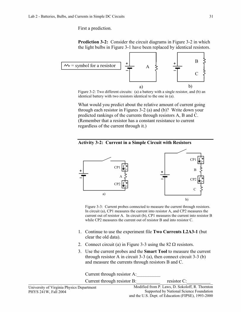
Prediction 3-2: Consider the circuit diagrams in Figure 3-2 in which the light bulbs in Figure 3-1 have been replaced by identical resistors.
= symbol for a resistor AB
C
a) b) Figure 3-2: Two different circuits: (a) a battery with a single resistor, and (b) an identical battery with two resistors identical to the one in (a). What would you predict about the relative amount of current going through each resistor in Figures 3-2 (a) and (b)? Write down your predicted rankings of the currents through resistors A, B and C. (Remember that a resistor has a constant resistance to current regardless of the current through it.) Activity 3-2: Current in a Simple Circuit with Resistors
CP1
CP2CP2
CP1
A
B
Ca)
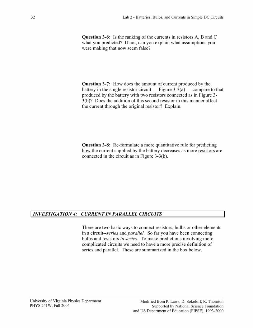
b) Figure 3-3: Current probes connected to measure the current through resistors. In circuit (a), CP1 measures the current into resistor A, and CP2 measures the current out of resistor A. In circuit (b), CP1 measures the current into resistor B while CP2 measures the current out of resistor B and into resistor C.
1. Continue to use the experiment file Two Currents L2A3-1 (but clear the old data).
2. Connect circuit (a) in Figure 3-3 using the 82 Ω resistors. 3. Use the current probes and the Smart Tool to measure the current
through resistor A in circuit 3-3 (a), then connect circuit 3-3 (b) and measure the currents through resistors B and C.
Current through resistor A:__________ Current through resistor B:__________ resistor C:__________
32 Lab 2 - Batteries, Bulbs, and Currents in Simple DC Circuits
Modified from P. Laws, D. Sokoloff, R. Thornton Supported by National Science Foundation
and US Department of Education (FIPSE), 1993-2000
University of Virginia Physics Department PHYS 241W, Fall 2004
Question 3-6: Is the ranking of the currents in resistors A, B and C what you predicted? If not, can you explain what assumptions you were making that now seem false?
Question 3-7: How does the amount of current produced by the battery in the single resistor circuit — Figure 3-3(a) — compare to that produced by the battery with two resistors connected as in Figure 3-3(b)? Does the addition of this second resistor in this manner affect the current through the original resistor? Explain.
Question 3-8: Re-formulate a more quantitative rule for predicting how the current supplied by the battery decreases as more resistors are connected in the circuit as in Figure 3-3(b).
INVESTIGATION 4: CURRENT IN PARALLEL CIRCUITS There are two basic ways to connect resistors, bulbs or other elements in a circuit--series and parallel. So far you have been connecting bulbs and resistors in series. To make predictions involving more complicated circuits we need to have a more precise definition of series and parallel. These are summarized in the box below.
Lab 2 - Batteries, Bulbs, and Currents in Simple DC Circuits 33
Modified from P. Laws, D. Sokoloff, R. Thornton Supported by National Science Foundation
and the U.S. Dept. of Education (FIPSE), 1993-2000
University of Virginia Physics Department PHYS 241W, Fall 2004
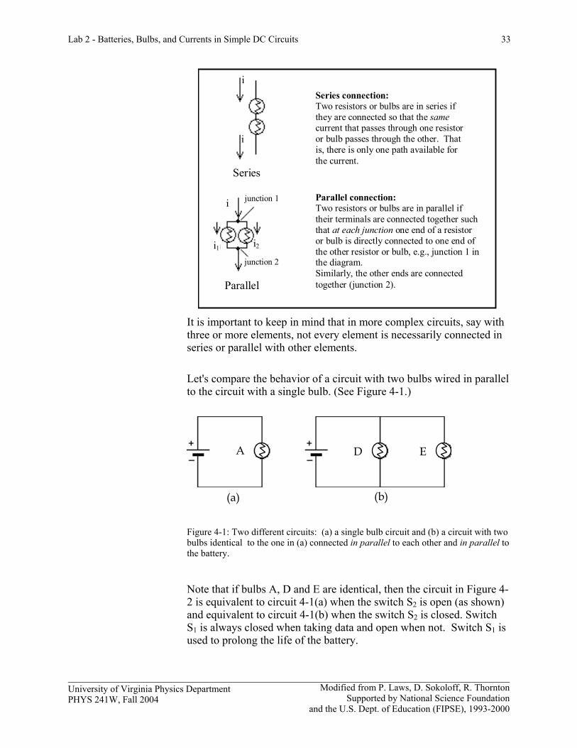
Series connection:Two resistors or bulbs are in series if they are connected so that the same current that passes through one resistor or bulb passes through the other. That is, there is only one path available for the current.
Series
Parallel connection:Two resistors or bulbs are in parallel if their terminals are connected together such that at each junction one end of a resistor or bulb is directly connected to one end of the other resistor or bulb, e.g., junction 1 in the diagram. Similarly, the other ends are connected together (junction 2). Parallel
junction 2
junction 1
i2i1
i
i
i
It is important to keep in mind that in more complex circuits, say with three or more elements, not every element is necessarily connected in series or parallel with other elements. Let's compare the behavior of a circuit with two bulbs wired in parallel to the circuit with a single bulb. (See Figure 4-1.)
(a) (b)
A D E
Figure 4-1: Two different circuits: (a) a single bulb circuit and (b) a circuit with two bulbs identical to the one in (a) connected in parallel to each other and in parallel to the battery.
Note that if bulbs A, D and E are identical, then the circuit in Figure 4-2 is equivalent to circuit 4-1(a) when the switch S2 is open (as shown) and equivalent to circuit 4-1(b) when the switch S2 is closed. Switch S1 is always closed when taking data and open when not. Switch S1 is used to prolong the life of the battery.
34 Lab 2 - Batteries, Bulbs, and Currents in Simple DC Circuits
Modified from P. Laws, D. Sokoloff, R. Thornton Supported by National Science Foundation
and US Department of Education (FIPSE), 1993-2000
University of Virginia Physics Department PHYS 241W, Fall 2004
D E
S2S1
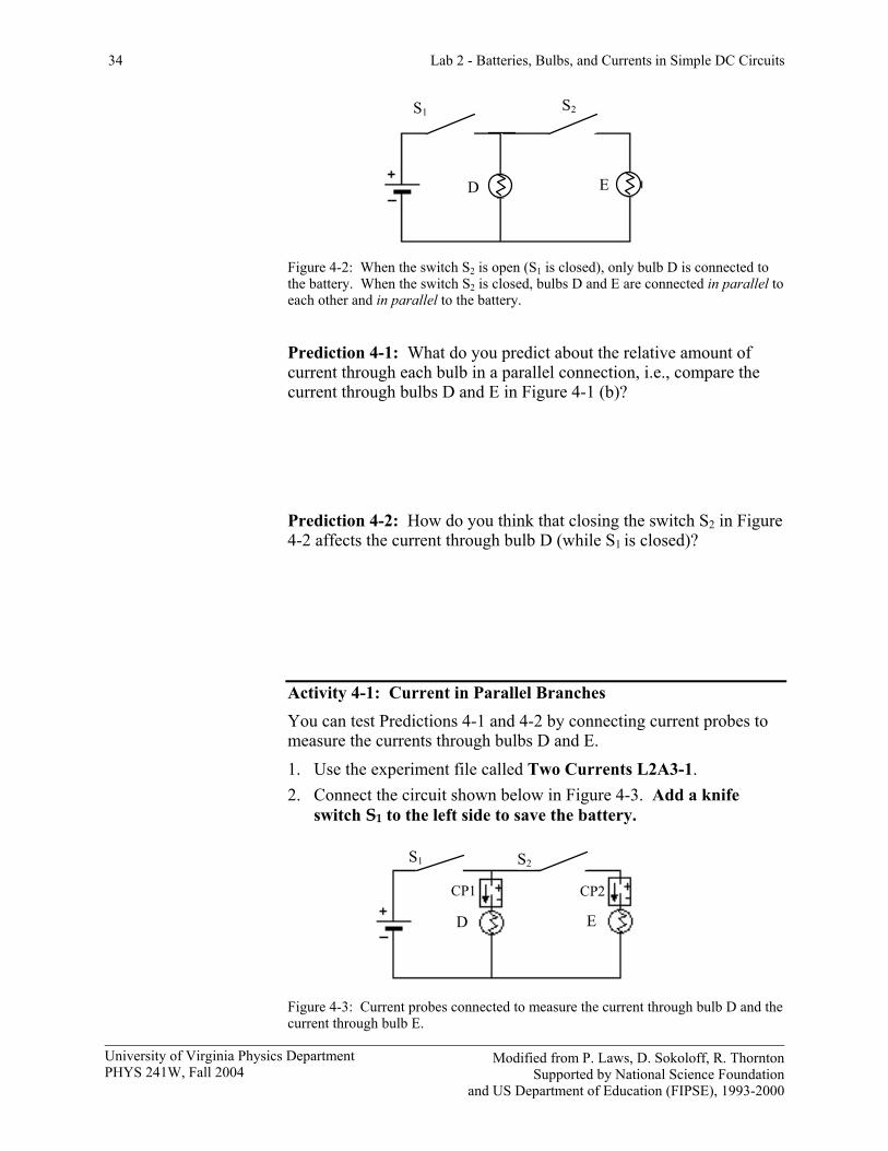
Figure 4-2: When the switch S2 is open (S1 is closed), only bulb D is connected to the battery. When the switch S2 is closed, bulbs D and E are connected in parallel to each other and in parallel to the battery.
Prediction 4-1: What do you predict about the relative amount of current through each bulb in a parallel connection, i.e., compare the current through bulbs D and E in Figure 4-1 (b)?
Prediction 4-2: How do you think that closing the switch S2 in Figure 4-2 affects the current through bulb D (while S1 is closed)?
Activity 4-1: Current in Parallel Branches You can test Predictions 4-1 and 4-2 by connecting current probes to measure the currents through bulbs D and E. 1. Use the experiment file called Two Currents L2A3-1. 2. Connect the circuit shown below in Figure 4-3. Add a knife
switch S1 to the left side to save the battery.
D E
CP2CP1
S2S1
Figure 4-3: Current probes connected to measure the current through bulb D and the current through bulb E.
Lab 2 - Batteries, Bulbs, and Currents in Simple DC Circuits 35
Modified from P. Laws, D. Sokoloff, R. Thornton Supported by National Science Foundation
and the U.S. Dept. of Education (FIPSE), 1993-2000
University of Virginia Physics Department PHYS 241W, Fall 2004
3. Begin graphing the currents through both probes with S1 closed then close the switch S2 for a second or so, open it for a second or so, and then close it again.
4. Print one set of graphs for your group. 5. Use the Smart Tool to measure both currents. Switch S2 open: Current through bulb D:_____Current through bulb E:_____ Switch S2 closed: Current through bulb D:_____Current through bulb E:_____
Question 4-1: Did closing the switch S2 and connecting bulb E in parallel with bulb D significantly affect the current through bulb D? How do you know? (Note: you are making a very significant change in the circuit. Think about whether the new current through D when the switch is closed reflects this.)
You have already seen that the voltage maintained by a battery doesn't change appreciably no matter what is connected to it (i.e. an ideal battery is a constant voltage source). But what about the current through the battery? Is it always the same no matter what is connected to it, or does it change depending on the circuit? This is what you will investigate next. Prediction 4-3: What do you predict about the amount of current through the battery in the parallel bulb circuit--Figure 4-1 (b)--compared to that through the single bulb circuit--Figure 4-1 (a)? Explain. Activity 4-2: Current Through the Battery 1. Test your prediction with the circuit shown in Figure 4-4. Use the
same experiment file, Two Currents L2A3-1, as in the previous
36 Lab 2 - Batteries, Bulbs, and Currents in Simple DC Circuits
Modified from P. Laws, D. Sokoloff, R. Thornton Supported by National Science Foundation
and US Department of Education (FIPSE), 1993-2000
University of Virginia Physics Department PHYS 241W, Fall 2004
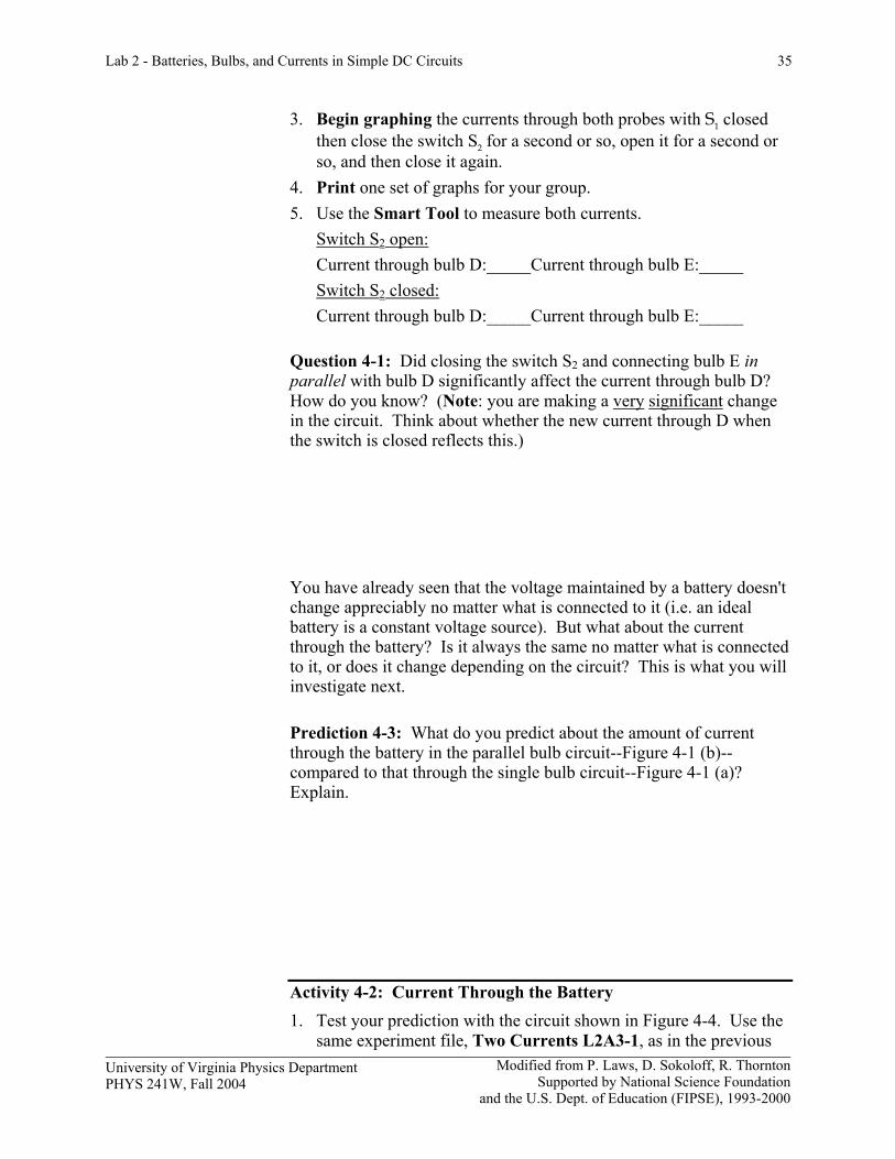
activities. Add a switch S1 in the left hand circuit below to save the battery.
D E
S2
CP1CP2
S1
Figure 4-4: Current probes connected to measure the current through the battery and the current through bulb D.
2. Begin graphing while closing and opening the switch S2 as before. Print one set of graphs for your group. Label on your graphs when the switch S2 is open and when it is closed. Remember that switch S1 is always closed when taking data, but open when not in order to save the battery.
3. Measure the currents through the battery and through bulb D. Switch S2 open: Current through battery:_____Current through bulb D:____ Switch S2 closed: Current through battery:_____Current through bulb D:____
Question 4-2: Does the current through the battery change as you predicted? If not, why not? Question 4-3: Does the addition of more bulbs in parallel increase, decrease or not change the total resistance of the circuit?
INVESTIGATION 5: MORE COMPLEX SERIES AND PARALLEL CIRCUITS Now you can apply your knowledge to some more complex circuits. Consider the circuit consisting of a battery and two bulbs, A and B, in
Lab 2 - Batteries, Bulbs, and Currents in Simple DC Circuits 37
Modified from P. Laws, D. Sokoloff, R. Thornton Supported by National Science Foundation
and the U.S. Dept. of Education (FIPSE), 1993-2000
University of Virginia Physics Department PHYS 241W, Fall 2004
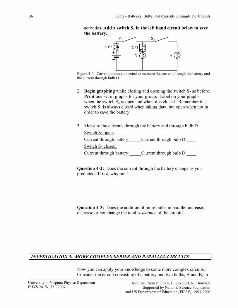
series shown in Figure 5-1(a). What will happen if you add a third bulb, C, in parallel with bulb B as shown in Figure 5-1(b)? You should be able to predict the relative brightness of A, B, and C based on previous observations. An important tough question is: how does the brightness of A change when C is connected in parallel to B?
Figure 5-1: Two circuits with identical components
Question 5-1: In Figure 5-1 (b) is bulb A in series with bulb B? with bulb C? or with a combination of bulbs B and C? (You may want to go back to the definitions of series and parallel connections.)
Question 5-2: In Figure 5-1 (b) are bulbs B and C connected in series or in parallel with each other, or neither?
Question 5-3: Is the resistance of the combination A, B and C in Figure 5-1 (b) larger than, smaller than or the same as the combination of A and B in Figure 5-1 (a)?
A
B
(a) (b)
A
B C
38 Lab 2 - Batteries, Bulbs, and Currents in Simple DC Circuits
Modified from P. Laws, D. Sokoloff, R. Thornton Supported by National Science Foundation
and US Department of Education (FIPSE), 1993-2000
University of Virginia Physics Department PHYS 241W, Fall 2004
Prediction 5-1: Predict how the current through bulb A will change, if at all, when circuit 5-1 (a) is changed to 5-1 (b) (when bulb C is added in parallel to bulb B). What will happen to the brightness of bulb A? Explain the reasons for your predictions.
Prediction 5-2: Predict how the current through bulb B will change, if at all, when circuit 5-1 (a) is changed to 5-1 (b) (when bulb C is added in parallel to bulb B). What will happen to the brightness of bulb B? Explain the reasons for your predictions. (This is difficult to do without a calculation, but at least explain your considerations.)
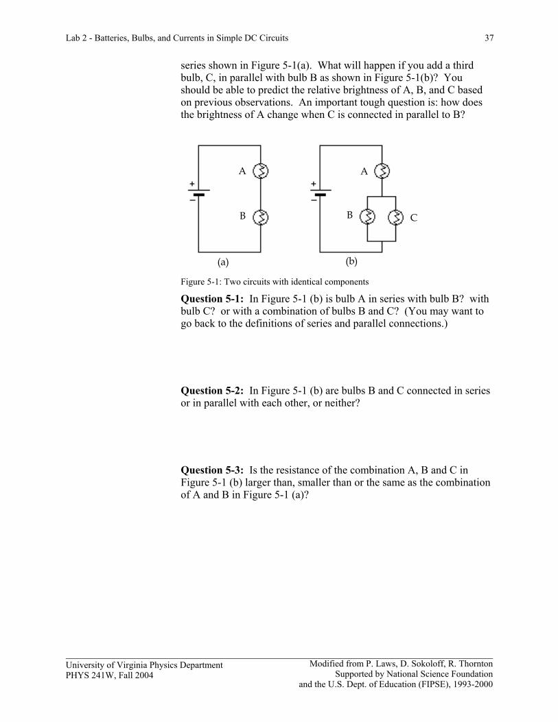
Activity 5-1: A More Complex Circuit 1. Set up the circuit shown in Figure 5-2(a). Add a switch to the left
side to save the battery. Convince yourself that this circuit is identical to Figure 5-1 (a) when the switch, S, is open, and to Figure 5-1 (b) when the switch is closed.
2. Connect the two current probes as shown in Figure 5-2(b). Be
sure you added a switch next to the battery to save the battery. Open the experiment file Two Currents L2A3-1, if it is not already opened.
- +
+ - CP1
CP2
(a) (b)
B B
A A
C C
S1
S2 S2
S1
Figure 5-2: (a) Circuit equivalent to Figure 5-1 (a) when the switch S2 is open and to Figure 5-1 (b) when the switch S2 is closed. (b) Same circuit with current probes connected to measure the current through bulb A (CP1) and the current through bulb B (CP2). Switch S1 is always closed when taking data.
Lab 2 - Batteries, Bulbs, and Currents in Simple DC Circuits 39
Modified from P. Laws, D. Sokoloff, R. Thornton Supported by National Science Foundation
and the U.S. Dept. of Education (FIPSE), 1993-2000
University of Virginia Physics Department PHYS 241W, Fall 2004
3. Close the battery switch S1 and begin graphing. Observe what
happens to the current through bulb A (i.e. through the battery) and the current through bulb B when the switch S2 to bulb C is opened and closed.
4. Open the battery switch S1, and print one set of graphs for your group. Use the Smart Tool to find the following information:
Without bulb C in the circuit: current through A:___________ current through B:___________ With bulb C in the circuit: current through A:___________ current through B:___________ Question 5-4: What happened to the brightness of bulbs A and B as the switch to bulb C was opened and closed? Compare to your predictions.
Question 5-5: What happens to the current through the battery when bulb C is added into the circuit? What do you conclude happens to the total resistance in the circuit?
40 Lab 2 - Batteries, Bulbs, and Currents in Simple DC Circuits
Modified from P. Laws, D. Sokoloff, R. Thornton Supported by National Science Foundation
and US Department of Education (FIPSE), 1993-2000
University of Virginia Physics Department PHYS 241W, Fall 2004