Embed Size (px)
Citation preview
Lab Manual (1)
Lab-2: Permanent Magnet Brushed DC Motor 1 Objectives and Overview The goals for this laboratory experiment are:
• to fully characterize a small industrial ¼ HP 48V Permanent Magnet DC (PMDC) Motor; • to observe the load characteristics when the motor is supplied from a variable DC souce; • to observe the load characteristics when the motor is supplied from a DC-DC converter
with variable duty-cycle. By doing a set of measurements, the students will determine the motor torque/voltage
constant tk , the armature winding + brush resistance aR , combined friction/loss torque as a function of speed ( )rfricT ω , and the moment of inertia rotorJ . Based on the determined parameters, the students will develop a steady-state model (equivalent circuit) of the given motor, and then use the model to predict the torque-speed characteristics and compare them to the measured ones. The students will also use a DC-DC converter with Pulse Width Modulation (PWM) to control the motor by varying the duty-cycle d .
2 Preparation It is expected that the students have read and understood the corresponding chapter in the
Textbook and reviewed the lecture notes Module corresponding to DC Motors. The students should be familiar with the theory and principle of DC Machine operation and equivalent circuit. Also, make sure to review the DC-DC converter operation using PWM voltage control.
3 Apparatus
This lab includes the following components:
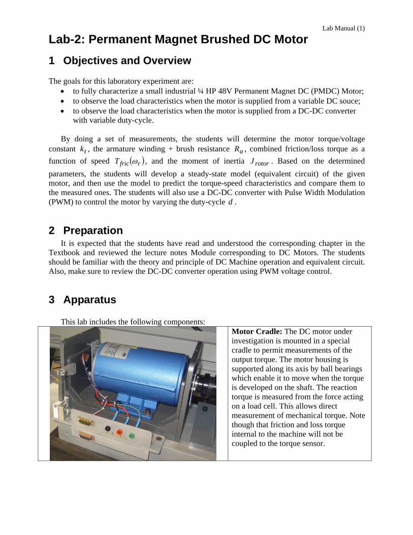
Motor Cradle: The DC motor under investigation is mounted in a special cradle to permit measurements of the output torque. The motor housing is supported along its axis by ball bearings which enable it to move when the torque is developed on the shaft. The reaction torque is measured from the force acting on a load cell. This allows direct measurement of mechanical torque. Note though that friction and loss torque internal to the machine will not be coupled to the torque sensor.
©Juri Jatskevich 2
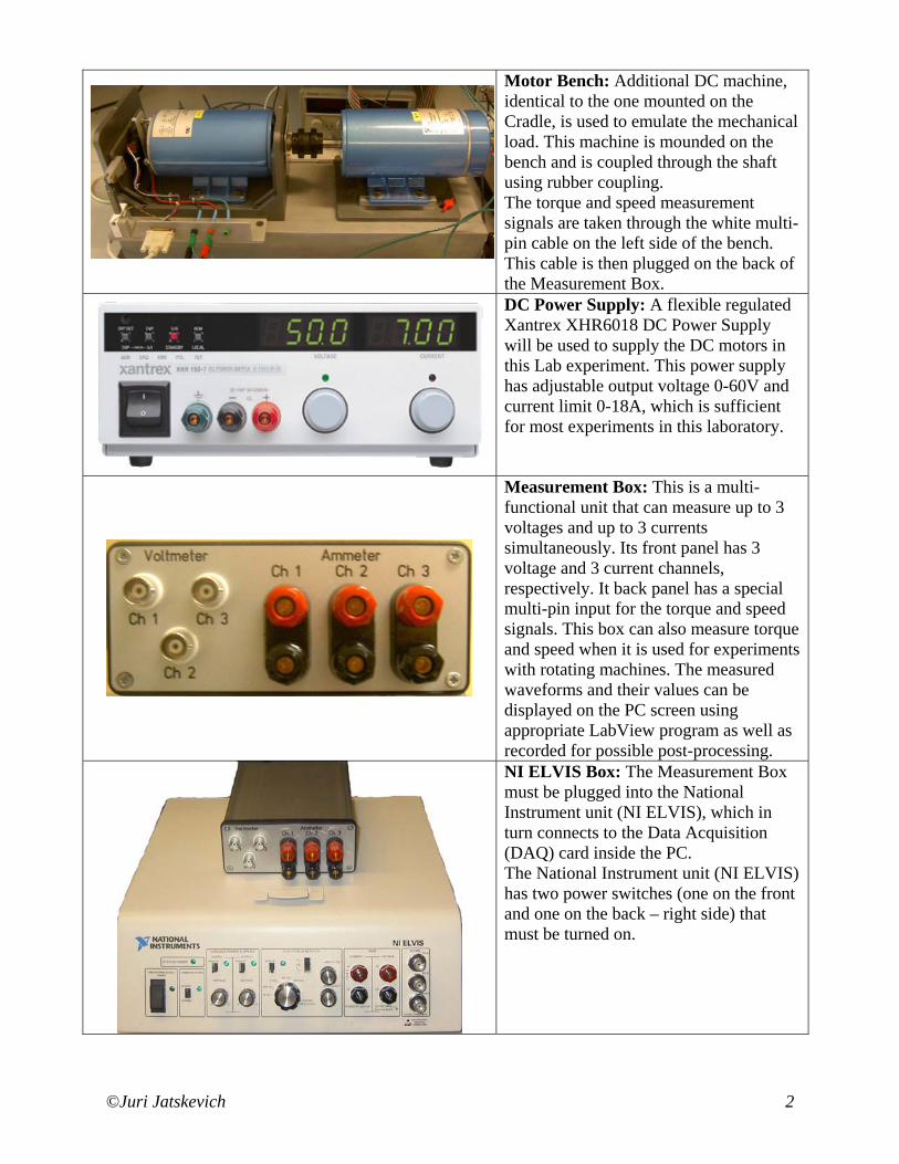
Motor Bench: Additional DC machine, identical to the one mounted on the Cradle, is used to emulate the mechanical load. This machine is mounded on the bench and is coupled through the shaft using rubber coupling. The torque and speed measurement signals are taken through the white multi-pin cable on the left side of the bench. This cable is then plugged on the back of the Measurement Box.
DC Power Supply: A flexible regulated Xantrex XHR6018 DC Power Supply will be used to supply the DC motors in this Lab experiment. This power supply has adjustable output voltage 0-60V and current limit 0-18A, which is sufficient for most experiments in this laboratory.
Measurement Box: This is a multi-functional unit that can measure up to 3 voltages and up to 3 currents simultaneously. Its front panel has 3 voltage and 3 current channels, respectively. It back panel has a special multi-pin input for the torque and speed signals. This box can also measure torque and speed when it is used for experiments with rotating machines. The measured waveforms and their values can be displayed on the PC screen using appropriate LabView program as well as recorded for possible post-processing.
NI ELVIS Box: The Measurement Box must be plugged into the National Instrument unit (NI ELVIS), which in turn connects to the Data Acquisition (DAQ) card inside the PC. The National Instrument unit (NI ELVIS) has two power switches (one on the front and one on the back – right side) that must be turned on.
©Juri Jatskevich 3
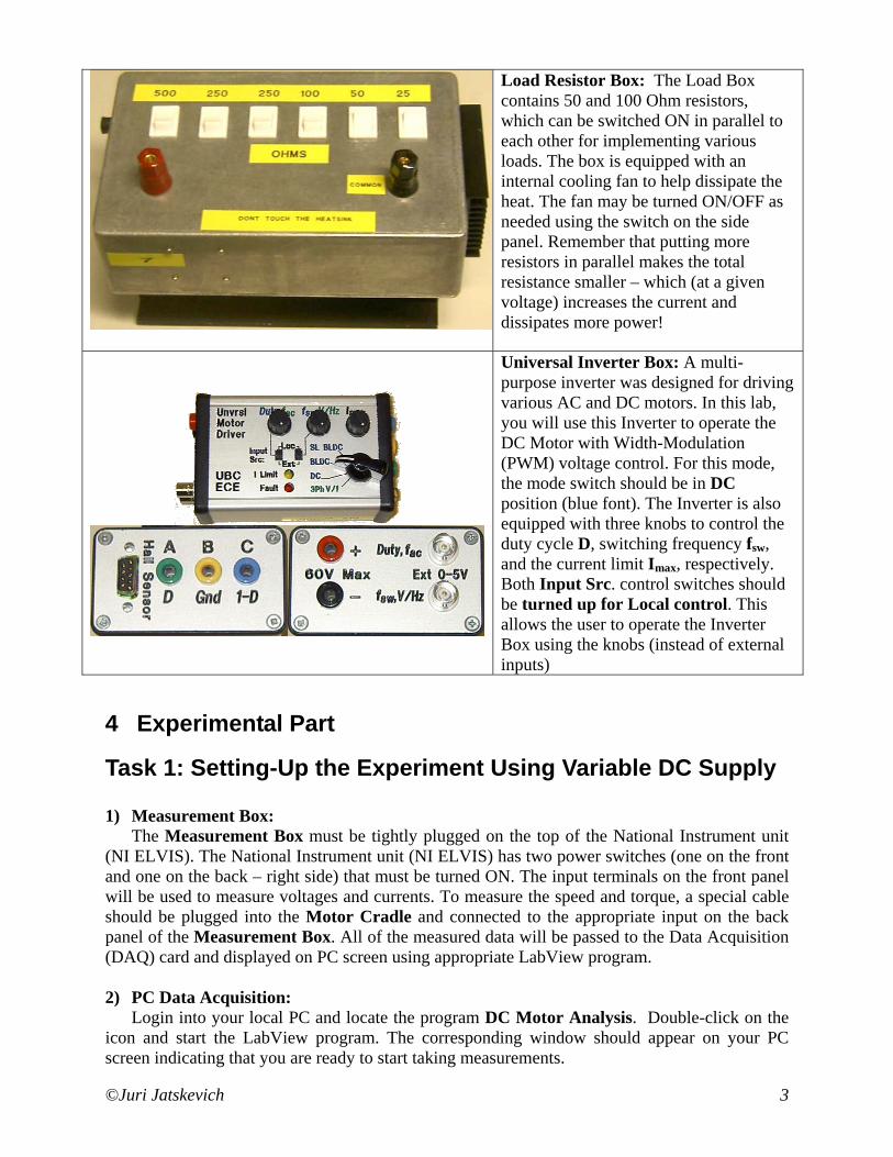
Load Resistor Box: The Load Box contains 50 and 100 Ohm resistors, which can be switched ON in parallel to each other for implementing various loads. The box is equipped with an internal cooling fan to help dissipate the heat. The fan may be turned ON/OFF as needed using the switch on the side panel. Remember that putting more resistors in parallel makes the total resistance smaller – which (at a given voltage) increases the current and dissipates more power!
Universal Inverter Box: A multi-purpose inverter was designed for driving various AC and DC motors. In this lab, you will use this Inverter to operate the DC Motor with Width-Modulation (PWM) voltage control. For this mode, the mode switch should be in DC position (blue font). The Inverter is also equipped with three knobs to control the duty cycle D, switching frequency fsw, and the current limit Imax, respectively. Both Input Src. control switches should be turned up for Local control. This allows the user to operate the Inverter Box using the knobs (instead of external inputs)
4 Experimental Part
Task 1: Setting-Up the Experiment Using Variable DC Supply 1) Measurement Box:
The Measurement Box must be tightly plugged on the top of the National Instrument unit (NI ELVIS). The National Instrument unit (NI ELVIS) has two power switches (one on the front and one on the back – right side) that must be turned ON. The input terminals on the front panel will be used to measure voltages and currents. To measure the speed and torque, a special cable should be plugged into the Motor Cradle and connected to the appropriate input on the back panel of the Measurement Box. All of the measured data will be passed to the Data Acquisition (DAQ) card and displayed on PC screen using appropriate LabView program. 2) PC Data Acquisition:
Login into your local PC and locate the program DC Motor Analysis. Double-click on the icon and start the LabView program. The corresponding window should appear on your PC screen indicating that you are ready to start taking measurements.
©Juri Jatskevich 4
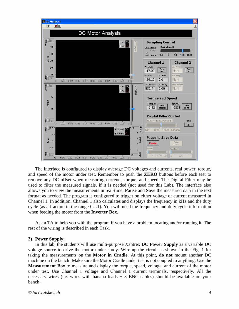
The interface is configured to display average DC voltages and currents, real power, torque,
and speed of the motor under test. Remember to push the ZERO buttons before each test to remove any DC offset when measuring currents, torque, and speed. The Digital Filter may be used to filter the measured signals, if it is needed (not used for this Lab). The interface also allows you to view the measurements in real-time, Pause and Save the measured data in the text format as needed. The program is configured to trigger on either voltage or current measured in Channel 1. In addition, Channel 1 also calculates and displays the frequency in kHz and the duty cycle (as a fraction in the range 0…1). You will need the frequency and duty cycle information when feeding the motor from the Inverter Box.
Ask a TA to help you with the program if you have a problem locating and/or running it. The rest of the wiring is described in each Task.
3) Power Supply:
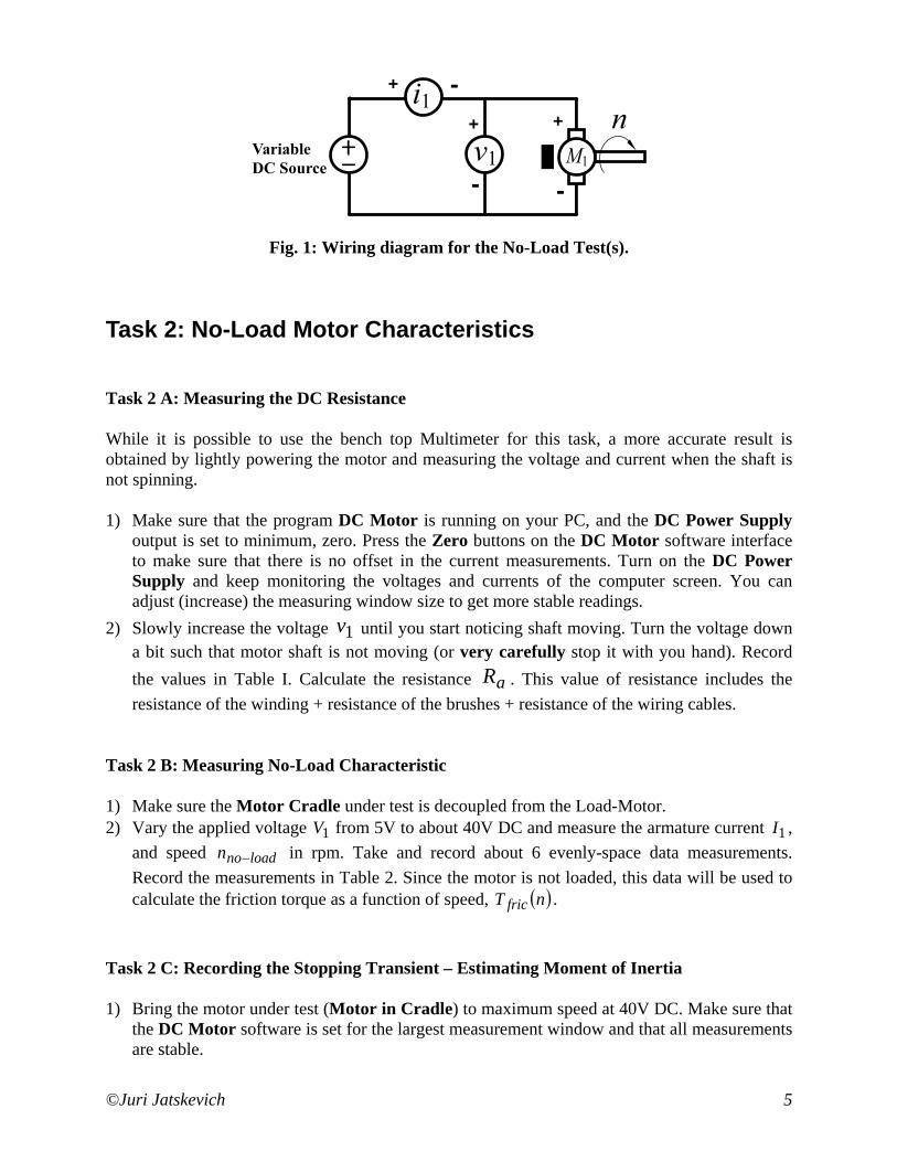
In this lab, the students will use multi-purpose Xantrex DC Power Supply as a variable DC voltage source to drive the motor under study. Wire-up the circuit as shown in the Fig. 1 for taking the measurements on the Motor in Cradle. At this point, do not mount another DC machine on the bench! Make sure the Motor Cradle under test is not coupled to anything. Use the Measurement Box to measure and display the torque, speed, voltage, and current of the motor under test. Use Channel 1 voltage and Channel 1 current terminals, respectively. All the necessary wires (i.e. wires with banana leads + 3 BNC cables) should be available on your bench.
©Juri Jatskevich 5
+ -
+
-
+
-
Fig. 1: Wiring diagram for the No-Load Test(s).
Task 2: No-Load Motor Characteristics
Task 2 A: Measuring the DC Resistance
While it is possible to use the bench top Multimeter for this task, a more accurate result is obtained by lightly powering the motor and measuring the voltage and current when the shaft is not spinning.
1) Make sure that the program DC Motor is running on your PC, and the DC Power Supply output is set to minimum, zero. Press the Zero buttons on the DC Motor software interface to make sure that there is no offset in the current measurements. Turn on the DC Power Supply and keep monitoring the voltages and currents of the computer screen. You can adjust (increase) the measuring window size to get more stable readings.
2) Slowly increase the voltage 1v until you start noticing shaft moving. Turn the voltage down a bit such that motor shaft is not moving (or very carefully stop it with you hand). Record the values in Table I. Calculate the resistance aR . This value of resistance includes the resistance of the winding + resistance of the brushes + resistance of the wiring cables.
Task 2 B: Measuring No-Load Characteristic
1) Make sure the Motor Cradle under test is decoupled from the Load-Motor. 2) Vary the applied voltage 1V from 5V to about 40V DC and measure the armature current 1I ,
and speed loadnon − in rpm. Take and record about 6 evenly-space data measurements. Record the measurements in Table 2. Since the motor is not loaded, this data will be used to calculate the friction torque as a function of speed, ( )nT fric .
Task 2 C: Recording the Stopping Transient – Estimating Moment of Inertia
1) Bring the motor under test (Motor in Cradle) to maximum speed at 40V DC. Make sure that the DC Motor software is set for the largest measurement window and that all measurements are stable.
©Juri Jatskevich 6
2) Simply disconnect the Power Supply by unplugging one of the wires and quickly push the PAUSE button to save the stopping transient. You can also adjust the position and zoom into the recorded interval to better view the transient response. Then, push the SAVE button to save the data in a text file. You may need to repeat this experiment to capture a sufficient interval of the stopping transient. You will use this data to calculate the moment of inertia
rotorJ for this motor in Task 5.
Task 3: Measuring Load Characteristics of the Motor
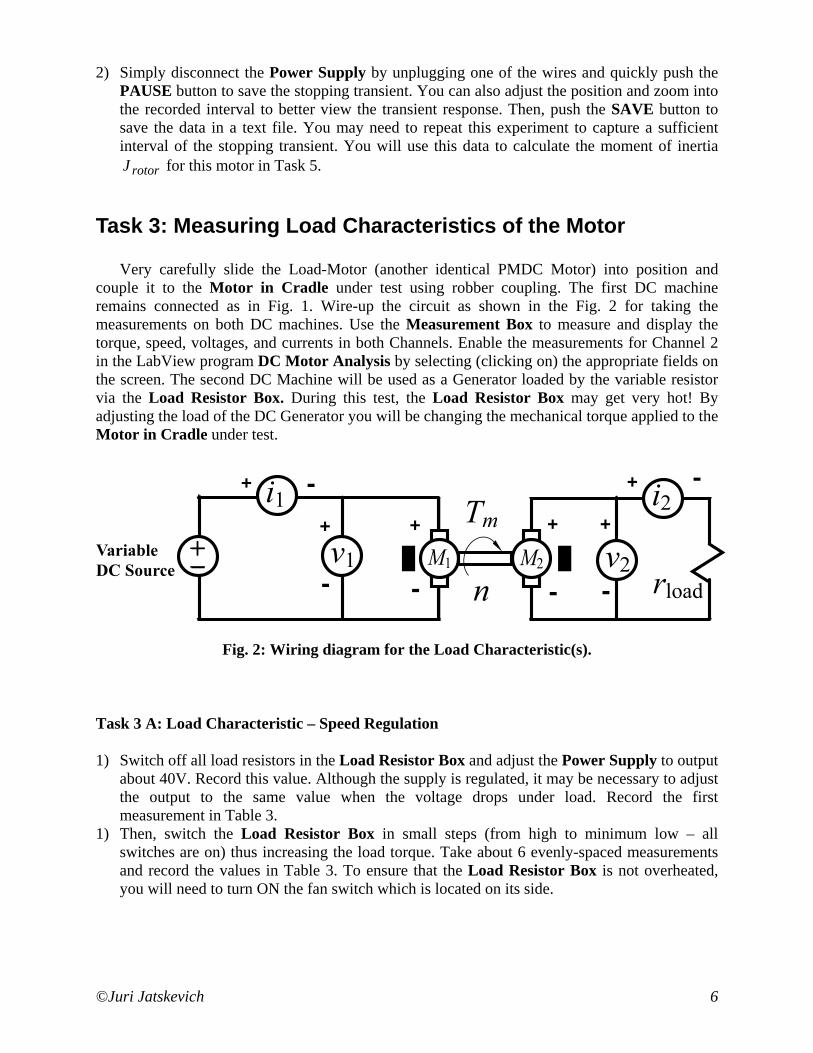
Very carefully slide the Load-Motor (another identical PMDC Motor) into position and couple it to the Motor in Cradle under test using robber coupling. The first DC machine remains connected as in Fig. 1. Wire-up the circuit as shown in the Fig. 2 for taking the measurements on both DC machines. Use the Measurement Box to measure and display the torque, speed, voltages, and currents in both Channels. Enable the measurements for Channel 2 in the LabView program DC Motor Analysis by selecting (clicking on) the appropriate fields on the screen. The second DC Machine will be used as a Generator loaded by the variable resistor via the Load Resistor Box. During this test, the Load Resistor Box may get very hot! By adjusting the load of the DC Generator you will be changing the mechanical torque applied to the Motor in Cradle under test.
+ - + -
+
-
+
-
+
-
+
-
Fig. 2: Wiring diagram for the Load Characteristic(s).
Task 3 A: Load Characteristic – Speed Regulation
1) Switch off all load resistors in the Load Resistor Box and adjust the Power Supply to output about 40V. Record this value. Although the supply is regulated, it may be necessary to adjust the output to the same value when the voltage drops under load. Record the first measurement in Table 3.
1) Then, switch the Load Resistor Box in small steps (from high to minimum low – all switches are on) thus increasing the load torque. Take about 6 evenly-spaced measurements and record the values in Table 3. To ensure that the Load Resistor Box is not overheated, you will need to turn ON the fan switch which is located on its side.
©Juri Jatskevich 7
Task 3 B: Speed Control by Adjusting Voltage
1) Switch on all load resistors in the Load Resistor Box. This will correspond to a mechanical load with maximum torque. The fan switch should be ON to provide the cooling.
2) Vary the DC Power Supply to output from 0 to 40V and record about 6 evenly-spaced measurements from almost zero speed (slightly spinning) to the maximum speed at 40 V. Write the measurements in Table 4.
Task 4: Motor Speed Control Using DC-DC Converter
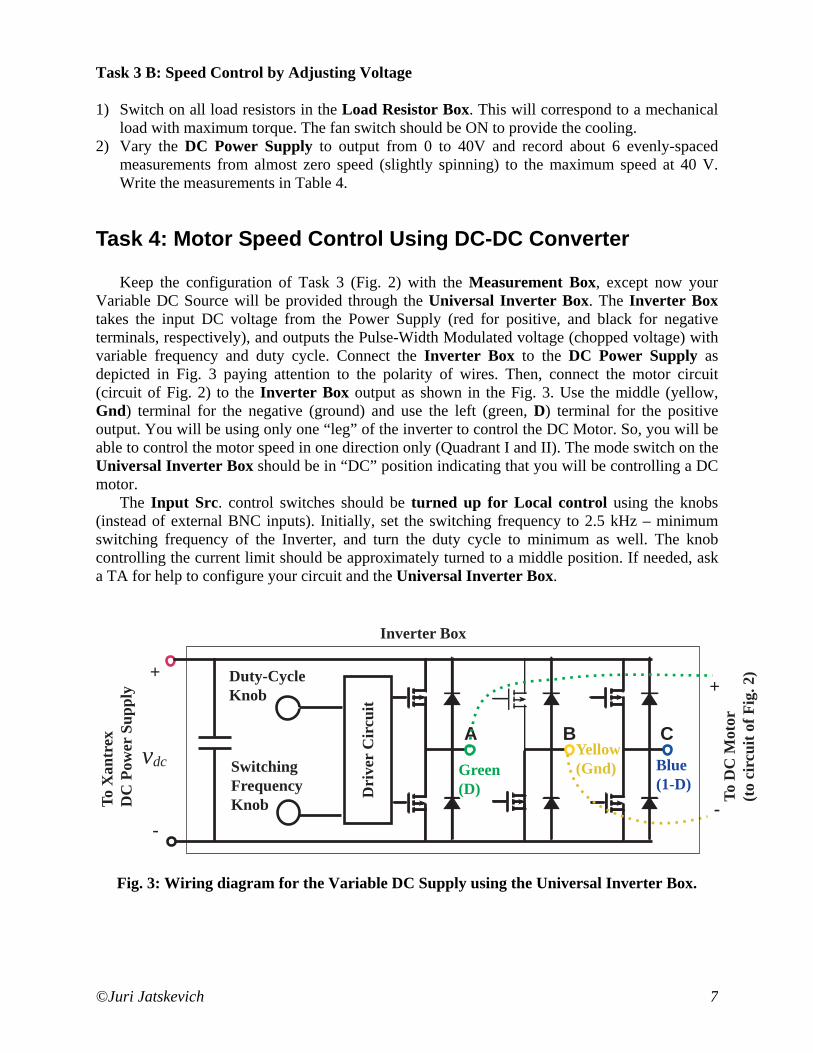
Keep the configuration of Task 3 (Fig. 2) with the Measurement Box, except now your Variable DC Source will be provided through the Universal Inverter Box. The Inverter Box takes the input DC voltage from the Power Supply (red for positive, and black for negative terminals, respectively), and outputs the Pulse-Width Modulated voltage (chopped voltage) with variable frequency and duty cycle. Connect the Inverter Box to the DC Power Supply as depicted in Fig. 3 paying attention to the polarity of wires. Then, connect the motor circuit (circuit of Fig. 2) to the Inverter Box output as shown in the Fig. 3. Use the middle (yellow, Gnd) terminal for the negative (ground) and use the left (green, D) terminal for the positive output. You will be using only one “leg” of the inverter to control the DC Motor. So, you will be able to control the motor speed in one direction only (Quadrant I and II). The mode switch on the Universal Inverter Box should be in “DC” position indicating that you will be controlling a DC motor.
The Input Src. control switches should be turned up for Local control using the knobs (instead of external BNC inputs). Initially, set the switching frequency to 2.5 kHz – minimum switching frequency of the Inverter, and turn the duty cycle to minimum as well. The knob controlling the current limit should be approximately turned to a middle position. If needed, ask a TA for help to configure your circuit and the Universal Inverter Box.
A B C
Dri
ver
Cir
cuit
SwitchingFrequencyKnob
Duty-CycleKnob
+
-
vdc
To D
C M
otor
(to
circ
uit o
f Fig
. 2)
Inverter Box
-
+
To X
antr
exD
C P
ower
Sup
ply
Green(D)
Yellow(Gnd) Blue
(1-D)
Fig. 3: Wiring diagram for the Variable DC Supply using the Universal Inverter Box.
©Juri Jatskevich 8
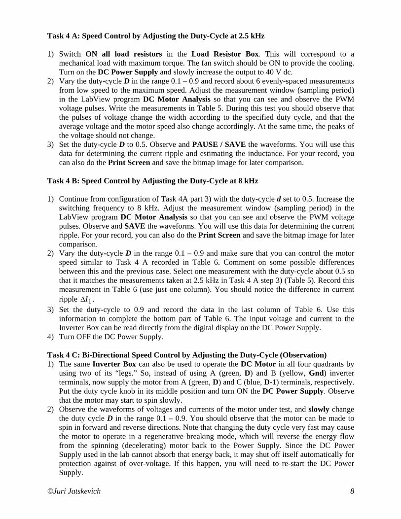
Task 4 A: Speed Control by Adjusting the Duty-Cycle at 2.5 kHz
1) Switch ON all load resistors in the Load Resistor Box. This will correspond to a mechanical load with maximum torque. The fan switch should be ON to provide the cooling. Turn on the DC Power Supply and slowly increase the output to 40 V dc.
2) Vary the duty-cycle D in the range 0.1 – 0.9 and record about 6 evenly-spaced measurements from low speed to the maximum speed. Adjust the measurement window (sampling period) in the LabView program DC Motor Analysis so that you can see and observe the PWM voltage pulses. Write the measurements in Table 5. During this test you should observe that the pulses of voltage change the width according to the specified duty cycle, and that the average voltage and the motor speed also change accordingly. At the same time, the peaks of the voltage should not change.
3) Set the duty-cycle D to 0.5. Observe and PAUSE / SAVE the waveforms. You will use this data for determining the current ripple and estimating the inductance. For your record, you can also do the Print Screen and save the bitmap image for later comparison.
Task 4 B: Speed Control by Adjusting the Duty-Cycle at 8 kHz
1) Continue from configuration of Task 4A part 3) with the duty-cycle d set to 0.5. Increase the switching frequency to 8 kHz. Adjust the measurement window (sampling period) in the LabView program DC Motor Analysis so that you can see and observe the PWM voltage pulses. Observe and SAVE the waveforms. You will use this data for determining the current ripple. For your record, you can also do the Print Screen and save the bitmap image for later comparison.
2) Vary the duty-cycle D in the range 0.1 – 0.9 and make sure that you can control the motor speed similar to Task 4 A recorded in Table 6. Comment on some possible differences between this and the previous case. Select one measurement with the duty-cycle about 0.5 so that it matches the measurements taken at 2.5 kHz in Task 4 A step 3) (Table 5). Record this measurement in Table 6 (use just one column). You should notice the difference in current ripple 1I∆ .
3) Set the duty-cycle to 0.9 and record the data in the last column of Table 6. Use this information to complete the bottom part of Table 6. The input voltage and current to the Inverter Box can be read directly from the digital display on the DC Power Supply.
4) Turn OFF the DC Power Supply.
Task 4 C: Bi-Directional Speed Control by Adjusting the Duty-Cycle (Observation) 1) The same Inverter Box can also be used to operate the DC Motor in all four quadrants by
using two of its “legs.” So, instead of using A (green, D) and B (yellow, Gnd) inverter terminals, now supply the motor from A (green, D) and C (blue, D-1) terminals, respectively. Put the duty cycle knob in its middle position and turn ON the DC Power Supply. Observe that the motor may start to spin slowly.
2) Observe the waveforms of voltages and currents of the motor under test, and slowly change the duty cycle D in the range 0.1 – 0.9. You should observe that the motor can be made to spin in forward and reverse directions. Note that changing the duty cycle very fast may cause the motor to operate in a regenerative breaking mode, which will reverse the energy flow from the spinning (decelerating) motor back to the Power Supply. Since the DC Power Supply used in the lab cannot absorb that energy back, it may shut off itself automatically for protection against of over-voltage. If this happen, you will need to re-start the DC Power Supply.

©Juri Jatskevich 9
Task 5: Calculations and Comparisons
This part must be included with your Lab Report:
Task 5 A: Determining Motor Parameters
1) Calculate the armature resistance aR and record the value in Table 1. 2) Calculate the torque constant from the no-load data obtained in Table 2, Task 2. This is
readily done by generating the value of r
aaat
RIVk
ω−
= for each measured point and
averaging the result. Also, calculate the voltage constant vk for the second DC Machine that was used as a generator and record this number in Table 3. You have to use the open-circuit voltage (before you connected the load resistor). What can you say about these two constants?
3) Calculate and the friction torque fricT in Table 2. Plot ( )nT fric as a function of rotor speed
n . This will require using the recently found torque constant tk . What can you say about the curve? Is the loss predominantly from sliding friction, viscous damping, or windage (turbulent airflow)?
4) Given that you now know the friction torque at all speeds, you can estimate with reasonable accuracy the system’s moment of inertia based on the rate of deceleration inferred from your
dtdEa measurement in Task 2 C. Calculate the moment of inertial rotorJ using your best
estimate of the friction torque at the speed where dt
dEa was measured. In particular, you will
have to use ( )rfrica
t
rotorrrotor T
dtdE
kJ
dtd
J ωω
== .
5) Based on the recorded data from Task 4, estimate the armature inductance aL . You will need to use the current ripple and voltage information from Task 4 A or B.
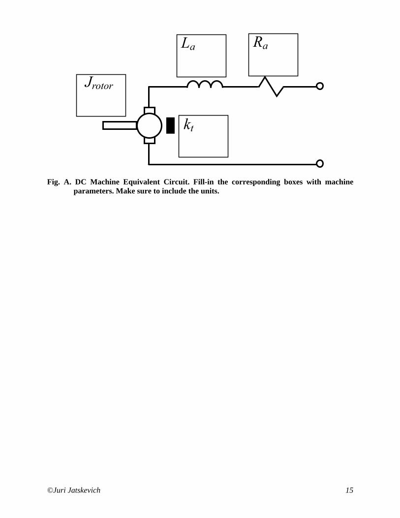
6) Complete Fig. A by filling-in the machine parameters.
Task 5 B: Equivalent Circuit vs. Measured Comparison
1) Use the equivalent circuit of the DC Machine and calculate the speed-torque characteristic ( )mTn . Don’t forget to include the effects of friction in your predicted curve. Superimpose
on the same plot the measured and the predicted characteristic. Comment of the result. 2) Use the equivalent circuit of the DC Machine and calculate the speed-voltage characteristic
( )1Vn . Don’t forget to include the effects of friction in your predicted curve. Superimpose on the same plot the characteristic measured in Task 3, Task 4, and the predicted characteristic. Comment of the result.
3) Plot the motor efficiency vs. current ( )1Iη characteristics based on the data measured in Task 3A as well as the model of the motor with the friction taken into account. Compare the results. Calculate/note at what current the motor has maximum efficiency.
4) Also, on different plots, plot the armature current and voltage (2 to 5 cycles) for the Task 4 A step 3) and Task 4 B step 1). What can you say about the effect of switching frequency?
©Juri Jatskevich 10
Task 5 C: Questions
1) What can you say about the accuracy of equivalent circuit? 2) Which method of the speed control (Task 3 or Task 4) in your opinion is more practical for
large motors and/or automotive/robotics applications? Briefly explain. 3) What can you say about the efficiency of your DC Motor and the efficiency of the Inverter
Box?
Task 6: Reporting Prepare the Lab Report that includes: 1) Title Page (all filled-in, with signatures) 2) Pages with the measured data and figures (pages 11 – 15), 3) Additional pages with calculations, discussions, and/or answers to questions in Task 5, 4) Brief Conclusion/Summary stating what you and your lab partner have learned in this Lab.
©Juri Jatskevich 11
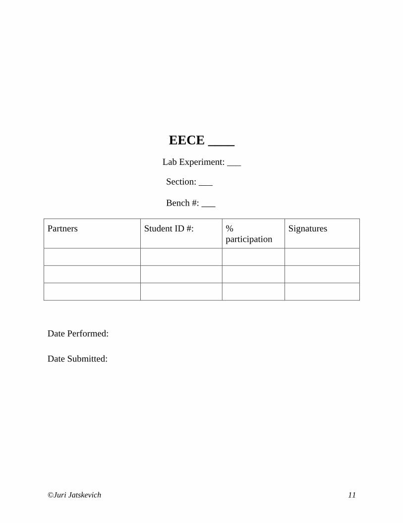
EECE ____
Lab Experiment: ___ Section: ___
Bench #: ___
Partners Student ID #: % participation
Signatures
Date Performed: Date Submitted:
©Juri Jatskevich 12
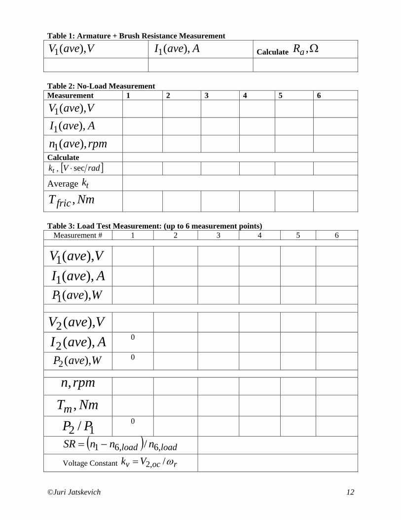
Table 1: Armature + Brush Resistance Measurement
VaveV ),(1 AaveI ),(1 Calculate Ω,aR
Table 2: No-Load Measurement Measurement 1 2 3 4 5 6
VaveV ),(1
AaveI ),(1
rpmaven ),(1
Calculate tk , [ ]radV sec⋅
Average tk
NmTfric ,
Table 3: Load Test Measurement: (up to 6 measurement points) Measurement # 1 2 3 4 5 6
VaveV ),(1
AaveI ),(1
WaveP ),(1
VaveV ),(2
AaveI ),(2 0
WaveP ),(2 0
rpmn,
NmTm ,
12 / PP 0
( ) loadload nnnSR ,6,61 /−=
Voltage Constant rocv Vk ω/,2=
©Juri Jatskevich 13
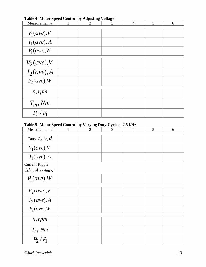
Table 4: Motor Speed Control by Adjusting Voltage Measurement # 1 2 3 4 5 6
VaveV ),(1
AaveI ),(1
WaveP ),(1
VaveV ),(2
AaveI ),(2
WaveP ),(2
rpmn,
NmTm ,
12 / PP
Table 5: Motor Speed Control by Varying Duty-Cycle at 2.5 kHz Measurement # 1 2 3 4 5 6
Duty-Cycle, d
VaveV ),(1
AaveI ),(1
Current Ripple AI ,1∆ at d=0.5
WaveP ),(1
VaveV ),(2
AaveI ),(2
WaveP ),(2
rpmn,
NmTm ,
12 / PP
©Juri Jatskevich 14
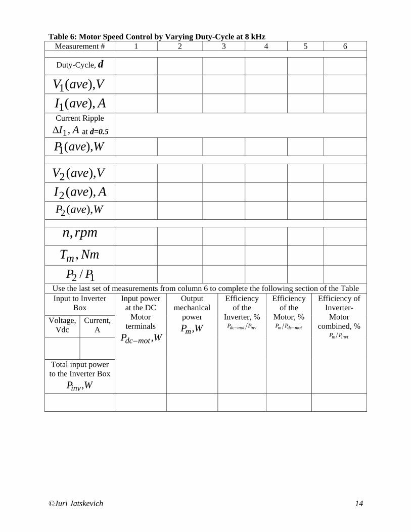
Table 6: Motor Speed Control by Varying Duty-Cycle at 8 kHz Measurement # 1 2 3 4 5 6
Duty-Cycle, d
VaveV ),(1
AaveI ),(1
Current Ripple AI ,1∆ at d=0.5
WaveP ),(1
VaveV ),(2
AaveI ),(2
WaveP ),(2
rpmn,
NmTm ,
12 / PP
Use the last set of measurements from column 6 to complete the following section of the Table Input to Inverter
Box Voltage,
Vdc Current,
A
Total input power to the Inverter Box
WPinv,
Input power at the DC
Motor terminals
WP motdc ,−
Output mechanical
power WPm ,
Efficiency of the
Inverter, % invmotdc PP −
Efficiency of the
Motor, % motdcm PP −
Efficiency of Inverter-Motor
combined, % invtm PP
©Juri Jatskevich 15
Fig. A. DC Machine Equivalent Circuit. Fill-in the corresponding boxes with machine parameters. Make sure to include the units.