Embed Size (px)
Citation preview
OM0053
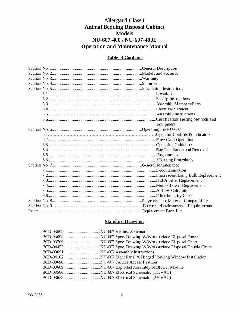
Allergard Class I Animal Bedding Disposal Cabinet
Models:
NU-607-400 NU-607-400E
Operation and Maintenance Manual
January, 2010 Revision 14
Manufactured By:
NuAire, Inc. 2100 Fernbrook Lane Plymouth, MN 55447
Toll-Free: 1-800-328-3352 In Minnesota: (763)-553-1270
Fax: (763)-553-0459
OM0053 2
Allergard Class I Animal Bedding Disposal Cabinet
Models NU-607-400 / NU-607-400E
Operation and Maintenance Manual
Table of Contents
Section No. 1...................................................................................General Description Section No. 2...................................................................................Models and Features Section No. 3...................................................................................Warranty Section No. 4...................................................................................Shipments Section No. 5...................................................................................Installation Instructions
5.1....................................................................................................Location 5.2....................................................................................................Set-Up Instructions 5.3....................................................................................................Assembly Members/Parts 5.4…………………………………………………………………Electrical Services 5.5…………………………………………………………………Assembly Instructions 5.6....................................................................................................Certification Testing Methods and
Equipment Section No. 6...................................................................................Operating the NU-607
6.1…………………………………………………………………Operator Controls & Indicators 6.2....................................................................................................Flow Gard Operation 6.3…………………………………………………………………Operating Guidelines 6.4…………………………………………………………………Bag Installation and Removal 6.5.....................................................................................................Ergonomics 6.6.....................................................................................................Cleaning Procedures
Section No. 7...................................................................................General Maintenance 7.1....................................................................................................Decontamination 7.2....................................................................................................Fluorescent Lamp Bulb Replacement 7.3....................................................................................................HEPA Filter Replacement 7.4....................................................................................................Motor/Blower Replacement 7.5....................................................................................................Airflow Calibration 7.6....................................................................................................Filter Integrity Check
Section No. 8...................................................................................Polycarbonate Material Compatibility Section No. 9……………………………………………………... Electrical/Environmental Requirements Insert………………………………………………………………Replacement Parts List
Standard Drawings
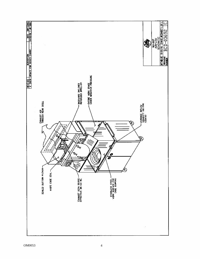
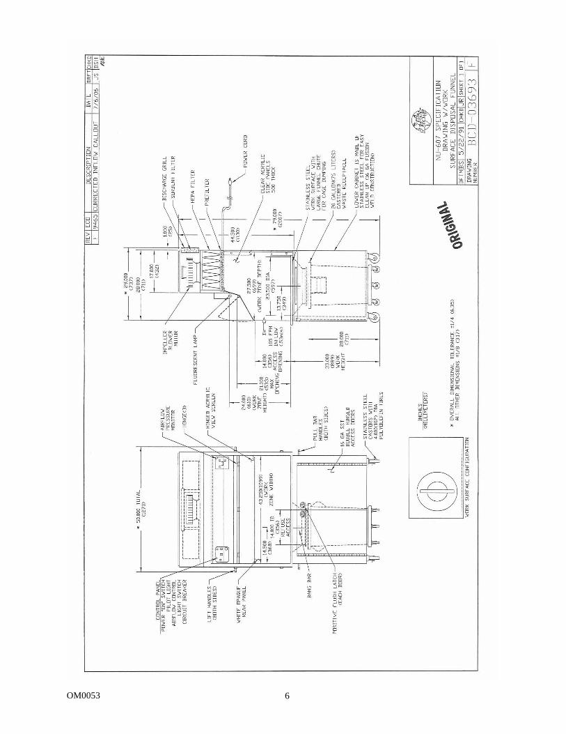
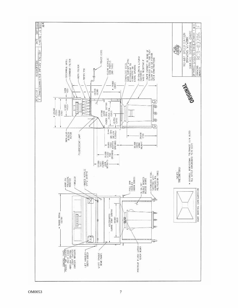
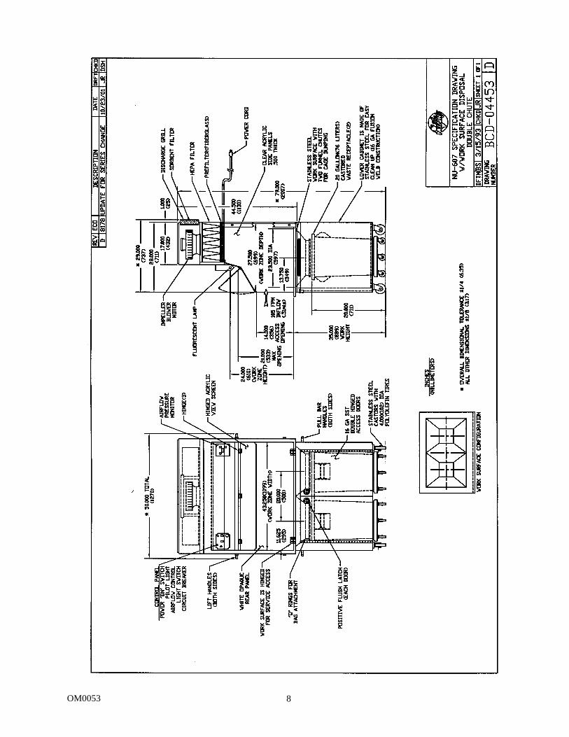
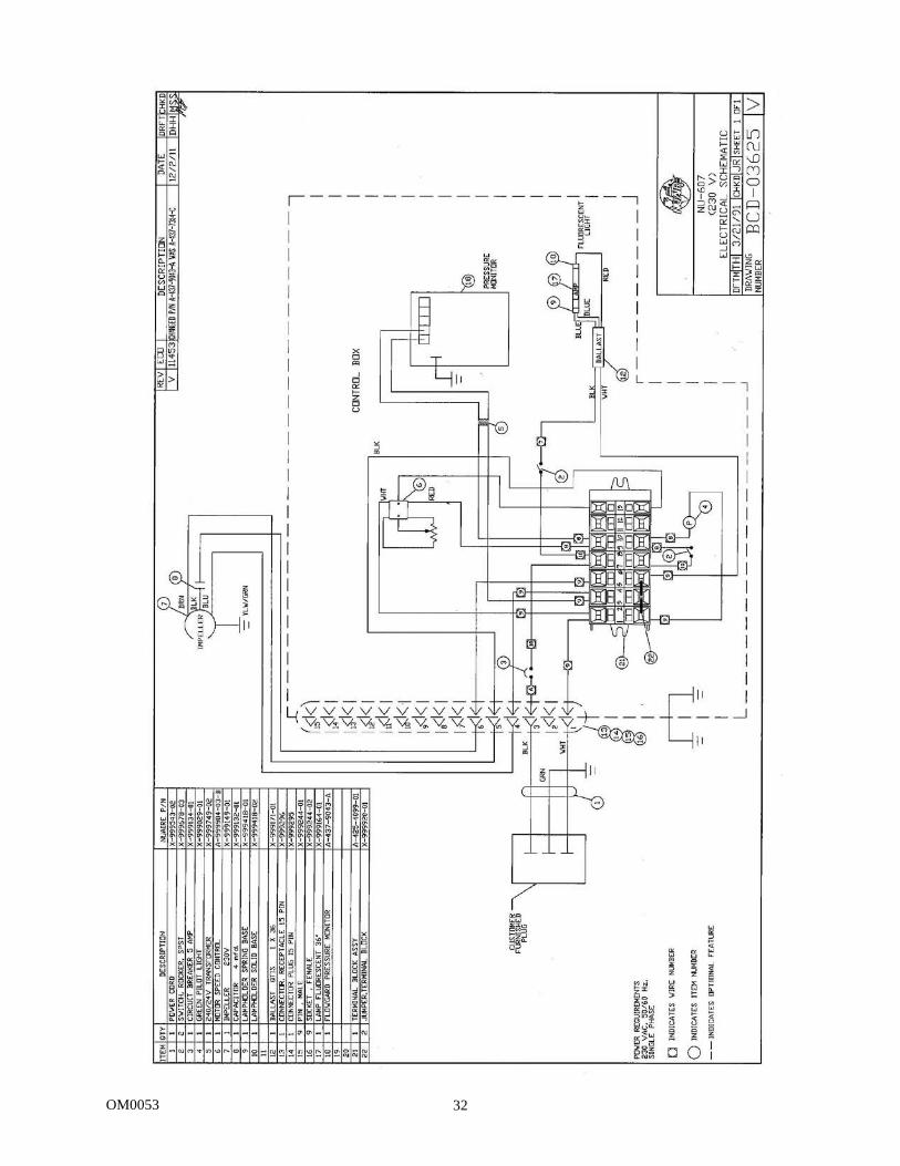
BCD-03692..................................NU-607 Airflow Schematic BCD-03693..................................NU-607 Spec. Drawing W/Worksurface Disposal Funnel BCD-03706..................................NU-607 Spec. Drawing W/Worksurface Disposal Chute BCD-04453..................................NU-607 Spec. Drawing W/Worksurface Disposal Double Chute BCD-03691..................................NU-607 Assembly Instructions BCD-04102..................................NU-607 Light Panel & Hinged Viewing Window Installation BCD-03690..................................NU-607 Service Access Features BCD-03689..................................NU-607 Exploded Assembly of Blower Module BCD-03586..................................NU-607 Electrical Schematic (115VAC) BCD-03625..................................NU-607 Electrical Schematic (230VAC)
OM0053 3
Allergard Class I Animal Bedding Disposal Cabinet
Models: NU-607-400/NU-607-400E
Operation and Maintenance Manual MANUFACTURED BY:
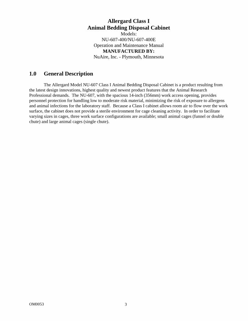
NuAire, Inc. - Plymouth, Minnesota 1.0 General Description
The Allergard Model NU-607 Class I Animal Bedding Disposal Cabinet is a product resulting from the latest design innovations, highest quality and newest product features that the Animal Research Professional demands. The NU-607, with the spacious 14-inch (356mm) work access opening, provides personnel protection for handling low to moderate risk material, minimizing the risk of exposure to allergens and animal infections for the laboratory staff. Because a Class I cabinet allows room air to flow over the work surface, the cabinet does not provide a sterile environment for cage cleaning activity. In order to facilitate varying sizes in cages, three work surface configurations are available; small animal cages (funnel or double chute) and large animal cages (single chute).
OM0053 4

OM0053 5
2.0 Models & Features The NU-607 is manufactured in one size. 4 ft. (1.2m)
OM0053 6
OM0053 7
OM0053 8
OM0053 9
3.0 Warranty
NuAire, Inc. warrants that it will repair F.O.B. its factory, or furnish without charge F.O.B. its factory, a similar part to replace any material in its equipment within 36 months after the date of sale if proved to the satisfaction of the company to have been defective at the time it was sold provided that all parts claimed defective shall be returned, properly identified to the company at its factory, charges prepaid. Factory installed equipment or accessories are warranted only to the extent guaranteed by the original manufacturer, and this warranty shall not apply to any portion of the equipment modified by the user. Claims under this warranty should be directed to NuAire, Inc. setting forth in detail the nature of the defect, the date of the initial installation and the serial and model number of the equipment.
This warranty shall not apply to any NuAire product or part thereof, which has been subject to misuse, abuse, accident, shipping damage, improper installation or service, or damage by fire, flood or acts of God. If the serial number of this product is altered, removed or defaced as to be illegible, the warranty shall be null and void in its entirety.
The warranty is for the sole benefit of the original purchaser and is not assignable or transferable. Prior to returning any item, for any reason, contact NuAire, Inc. for a Return Authorization Number. This number must accompany all returns. Any product shipped to NuAire without this number will be returned, refused shipment or collect freight. 4.0 Shipments
NuAire takes every reasonable precaution to assure that your Allergard cabinet arrives without damage. Motor carriers are carefully selected and shipping cartons have been specially designed to insure your purchase. However, damage can occur in any shipment and the following outlines the steps you should take on receipt of a NuAire Allergard cabinet to be sure that if damage has occurred, the proper claims and actions are taken immediately. 4.1 Damaged Shipments
4.1.1 Terms are factory, unless stated otherwise. Therefore, it is important to check each shipment before acceptance.
4.1.2 If there is visible damage, the material can be accepted after the driver makes a notation on
the consignee’s copy of the freight bill. Then an inspection must be made to verify the claim against the carrier. This inspection is the basis of your filing the claim against the carrier.
4.1.3 If concealed damage is found, it is absolutely necessary to NOTIFY THE FREIGHT AGENT
AT ONCE, and request an inspection. Without this inspection, the transportation company may not accept a claim for loss or damage. If the carrier will not perform the inspection, an affidavit must be prepared stating that he was contacted on a certain date and that he failed to comply with the request. This, along with other papers in the customer’s possession, will support the claim.
OM0053 10
5.0 Installation Instructions 5.1 Location
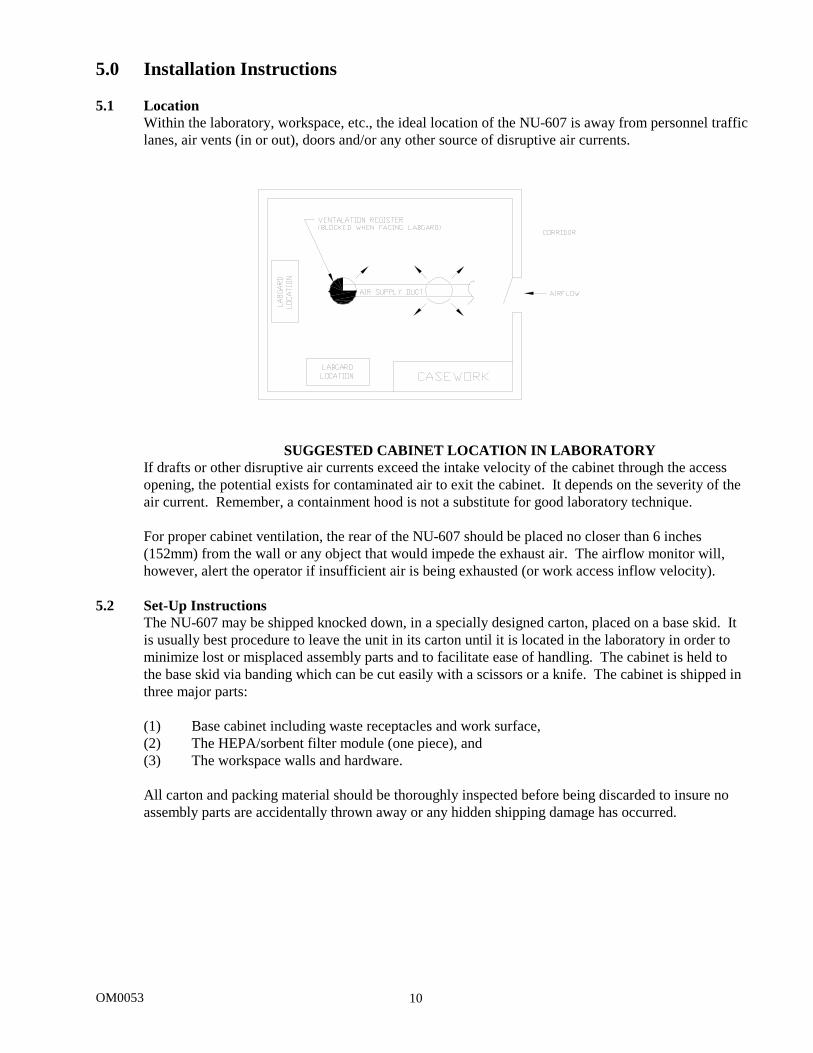
Within the laboratory, workspace, etc., the ideal location of the NU-607 is away from personnel traffic lanes, air vents (in or out), doors and/or any other source of disruptive air currents.
SUGGESTED CABINET LOCATION IN LABORATORY If drafts or other disruptive air currents exceed the intake velocity of the cabinet through the access opening, the potential exists for contaminated air to exit the cabinet. It depends on the severity of the air current. Remember, a containment hood is not a substitute for good laboratory technique. For proper cabinet ventilation, the rear of the NU-607 should be placed no closer than 6 inches (152mm) from the wall or any object that would impede the exhaust air. The airflow monitor will, however, alert the operator if insufficient air is being exhausted (or work access inflow velocity).
5.2 Set-Up Instructions
The NU-607 may be shipped knocked down, in a specially designed carton, placed on a base skid. It is usually best procedure to leave the unit in its carton until it is located in the laboratory in order to minimize lost or misplaced assembly parts and to facilitate ease of handling. The cabinet is held to the base skid via banding which can be cut easily with a scissors or a knife. The cabinet is shipped in three major parts: (1) Base cabinet including waste receptacles and work surface, (2) The HEPA/sorbent filter module (one piece), and (3) The workspace walls and hardware. All carton and packing material should be thoroughly inspected before being discarded to insure no assembly parts are accidentally thrown away or any hidden shipping damage has occurred.
OM0053 11
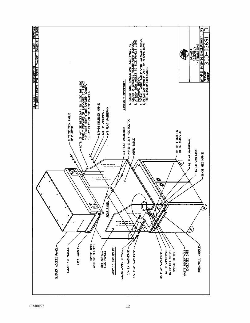
5.3 Assembly Members/Parts
The cabinet is assembled per Drawings BCD-04102 and BCD-03691. Before beginning assembly, make sure that all parts are accounted for as follows: (1) White acrylic back panel; 1 each (2) Clear acrylic side panels; 2 each (3) 2 each outside trim angles (4) 2 each inside trim angles NOTE: The inside trim angle has protruding studs on the angle that are inserted through the holes in
the acrylic walls.
(5) 4 each, sets of hardware (washer, lockwasher, and nut). (6) Polycarbonate view screen with light shield attached, and (7) 4 each, sets of #8-32 screws.
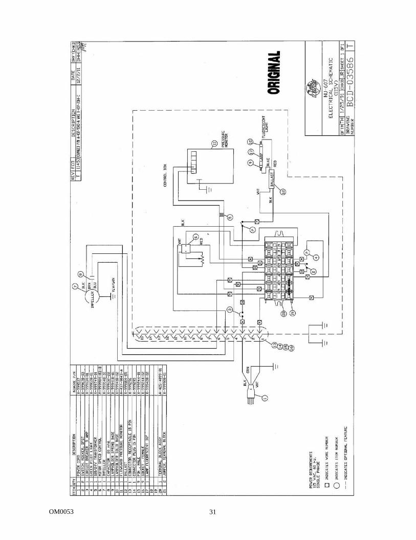
5.4 Electrical Services
The NU-607 is provided with an electrical power cord. The station requires 115 VAC, single phase power and is recommended to be on its own branch circuit, protected with a 15 Amp circuit breaker at the distribution panel. PLEASE NOTE, THIS UNIT CONTAINS AN ELECTRONIC BALLAST FOR THE FLUORESCENT LIGHTING. ELECTRONIC BALLASTS OPERATE WITH HIGH INRUSH CURRENT. IT IS NOT RECOMMENDED TO USE THIS PRODUCT WITH GROUND FAULT INTERRUPTERS (GFCI'S) BECAUSE THE BALLASTS MAY CAUSE THE GFCI TO TRIP.
OM0053 12
OM0053 13
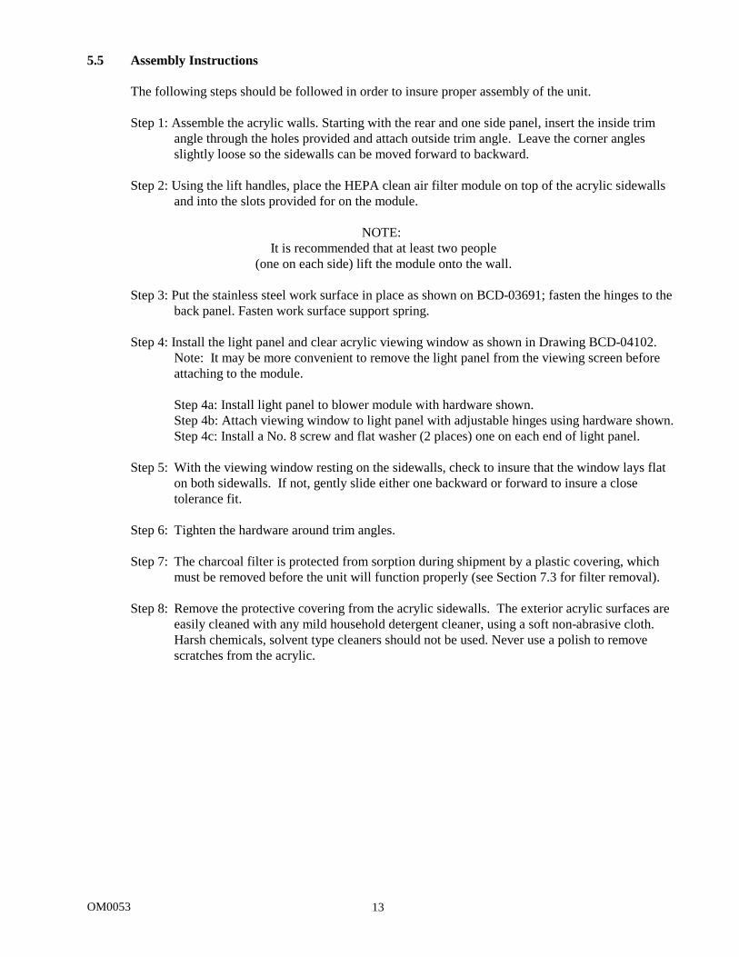
5.5 Assembly Instructions
The following steps should be followed in order to insure proper assembly of the unit. Step 1: Assemble the acrylic walls. Starting with the rear and one side panel, insert the inside trim
angle through the holes provided and attach outside trim angle. Leave the corner angles slightly loose so the sidewalls can be moved forward to backward.
Step 2: Using the lift handles, place the HEPA clean air filter module on top of the acrylic sidewalls
and into the slots provided for on the module.
NOTE: It is recommended that at least two people
(one on each side) lift the module onto the wall.
Step 3: Put the stainless steel work surface in place as shown on BCD-03691; fasten the hinges to the back panel. Fasten work surface support spring.
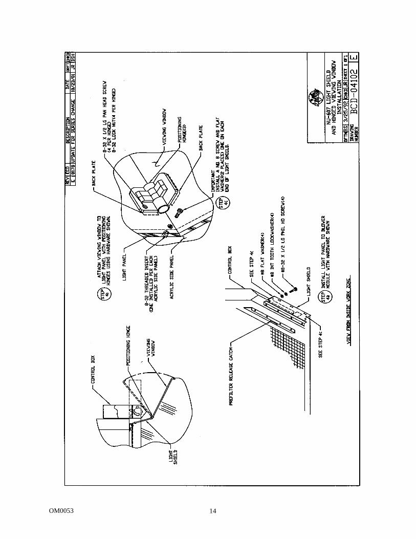
Step 4: Install the light panel and clear acrylic viewing window as shown in Drawing BCD-04102.
Note: It may be more convenient to remove the light panel from the viewing screen before attaching to the module.
Step 4a: Install light panel to blower module with hardware shown. Step 4b: Attach viewing window to light panel with adjustable hinges using hardware shown. Step 4c: Install a No. 8 screw and flat washer (2 places) one on each end of light panel.
Step 5: With the viewing window resting on the sidewalls, check to insure that the window lays flat
on both sidewalls. If not, gently slide either one backward or forward to insure a close tolerance fit.
Step 6: Tighten the hardware around trim angles. Step 7: The charcoal filter is protected from sorption during shipment by a plastic covering, which
must be removed before the unit will function properly (see Section 7.3 for filter removal). Step 8: Remove the protective covering from the acrylic sidewalls. The exterior acrylic surfaces are
easily cleaned with any mild household detergent cleaner, using a soft non-abrasive cloth. Harsh chemicals, solvent type cleaners should not be used. Never use a polish to remove scratches from the acrylic.
OM0053 14

OM0053 15
5.6 Certification Testing Methods and Equipment After installation and prior to use, NuAire recommends that the cabinet be certified or commissioned to factory standards. At a minimum, the following test should be performed. 1. HEPA filter leak test 2. Airflow velocity 3. Airflow smoke patterns Of these tests, in order to insure that no disruptive air currents are penetrating the air inflow barrier smoke flow tests must be performed. These tests must result in the containment of smoke passed around the perimeter of the work access opening. A smoke source shall be passed along the entire perimeter of the work opening edges, approximately 1.5 inches (38mm) outside the cabinet. The smoke shall show a smooth inward flow with no escape from the work access opening. IT IS RECOMMENDED THAT THESE TESTS BE PERFORMED BY A QUALIFIED TECHNICIAN WHO IS FAMILIAR WITH THE METHODS AND PROCEDURES FOR CERTIFYING SAFETY CABINETS. AFTER THE INITIAL CERTIFICATION, NUAIRE RECOMMENDS THAT THE CABINET BE RECERTIFIED AT A MINIMUM ON AN ANNUAL BASIS AND AFTER EVERY FILTER CHANGE OR MAINTENANCE ACTION OR ANY TIME THE OPERATOR FEELS IT IS NECESSARY. Note that NuAire cabinets, filters and seals provide premium performance; Quality Control in both design and manufacturing assure superior reliability. However, protection to the operator is so vital that certification to the performance requirements should be accomplished as stated to insure safety established by the factory standards.
OM0053 16
6.0 Operating the NU-607 6.1 Operator Controls and Indicators
The following is a description of the controls and indicators, (see location of control panel on Drawings BCD-03693 & BCD-03706). 6.1.1 Airflow Control
Airflow inside the unit is controlled by a Potentiometer behind a chrome pop-out button that is located on the instrument panel. To increase airflow, turn the airflow adjustment clockwise and counterclockwise to decrease airflow. The motor speed control should never be tampered with, except by a qualified technician who can measure airflow through the work access opening with a suitable velometer. Note that the motor/fan system is designed to minimize any requirement for the adjustment of motor speed as the HEPA filter loads up with contaminants.
6.1.2 Blower Switch
The blower switch applies power to the internal blower/motor when in the ON position.
6.1.3 Power “ON” Light A green neon light is located above the blower on/off switch and lights when power is applied to the motor blower. This switch also powers the Airflow Monitor.
6.1.4 Circuit Breaker
The entire cabinet is protected with a circuit breaker. The circuit breaker, in conjunction with the motor’s thermal protector, is designed to open under locked rotor or half-wave power condition. Should the circuit breaker open (pop-out button will appear) merely depress to reset. If the circuit breaker continually opens, a failure has occurred in the motor, solid-state speed controller or Airflow Monitor. Consult a qualified repair technician or NuAire, Inc. for replacement of necessary parts.
6.2 Flow Gard Operation
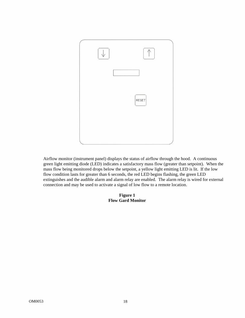
6.2.1 Overview The Flow Gard monitor (see Figure 1) uses a digital pressure transducer to monitor the cabinet's positive pressure plenum. The Flow Gard monitor indicates through LED's normal operation (green), as well as high alarm status (red) (HEPA filter loading) and low alarm status (red) (low airflow). The Flow Gard functions only when the cabinet blower is on. When the Flow Gard is turned on, it will go through a 4-minute warm-up period indicated by a series of blinking LED's. When the warm-up period is complete, the LED indicate will stop blinking and remain on. All user interaction is accomplished through the arrow and reset keys. IT IS RECOMMENDED THAT THE FLOWGARD BE CALIBRATED ANNUALLY DURING THE CERTIFICATION PROCESS.
OM0053 17
6.2.2 Nominal Airflow Calibration To calibrate the Flow Gard monitor, the cabinet must first be certified or set to nominal airflow values. Once the cabinet nominal airflows are set, perform the following procedure:
• Press and hold [] and [] arrow keys simultaneously for 3 seconds until the center green LED blinks. ALLOW UNIT TO RUN FOR A MINIMUM OF 2 MINUTES with the center green LED blinking.
• Press [RESET] key to enter the nominal airflow value (green LED will stop blinking and display normal).
Please note, after the initial calibration, the Flow Gard LED display will bounce around more than normal. After a few hours, the Flow Gard LED display will steady due to fuzzy logic or a learning program that averages the normal display. Once the Flow Gard has been calibrated, the high/low alarm limits are defaulted to activate with a pressure deviation of +0.13 inches (3mm) water gage from nominal. The pressure deviation translates to a reduction in airflow that is well within the operational tolerances of the cabinet.
6.2.3 Independent High/Low Alarm Calibration
If desired, the Flow Gard high or low alarm limit may be adjusted. However, to adjust the high or low alarm setpoint, the cabinet airflow must be altered to the desired alarm setpoint before the individual calibration point can be entered into the monitor. Once the cabinet high or low alarm limit airflows are set, perform the following procedure:
• Press and hold either the [] key for high alarm or [] key for low alarm for three seconds until
the Hi or Lo red LED blinks respectively. Allow unit to run for a minimum of 2 minutes with the respective LED blinking.
• Press [RESET] key to enter the high or low alarm setpoint. • Re-adjust airflow back to the nominal values.
The high or low alarm limit may be verified by adjusting the airflow to the alarm limit to induce an alarm condition.
6.2.4 Audible Pressure Alarm
The audible alarm should be activated whenever the pressure reaches the high or low alarm setpoint. However, once the alarm pressure is reached, it must stay on the alarm limit for 5 seconds consistently or it will not recognize it as an alarm. If at any time, the pressure returns to acceptable limits, the alarm would be reset and silenced. Once the 5 second period of constant alarm is present, the audible should sound for 30 seconds, then ringback 1 second every 10 seconds. If the Reset key is pressed, the alarm should be silenced for 5 minutes, then continue to ringback for 1 second every 10.
OM0053 18
Airflow monitor (instrument panel) displays the status of airflow through the hood. A continuous green light emitting diode (LED) indicates a satisfactory mass flow (greater than setpoint). When the mass flow being monitored drops below the setpoint, a yellow light emitting LED is lit. If the low flow condition lasts for greater than 6 seconds, the red LED begins flashing, the green LED extinguishes and the audible alarm and alarm relay are enabled. The alarm relay is wired for external connection and may be used to activate a signal of low flow to a remote location.
Figure 1
Flow Gard Monitor
OM0053 19
6.3 Operating Guidelines
6.3.1 The intent herein is to present general operating guidelines that will aid in the use of the Class I Containment Cabinet to control airborne contaminants of low to moderate risk.
6.3.2 Procedure protocols defined in terms of the barrier of control concepts unique to containment
cabinet must be developed in order to obtain the maximum potential for safety and protection. The pre-planning necessary to develop these protocols is based on several fundamental considerations, each of which will contribute to optimum benefits from the equipment:
a. Minimize disruption of “air curtain” b. Minimize room activity
6.3.3 The minimum number of items necessary should be placed into the cabinet to prevent
overloading, but the work should also be planned to minimize the number of times an operator’s hands and arms must enter and leave the air curtain at the open face. The ideal situation is to have everything needed for the complete procedure placed in the cabinet before starting, so that nothing need pass in or out through the air barrier at the face until the procedure is completed. This is especially important in working with moderate risk agents.
NOTE:
When working with agents of lower risk, it is not as important for all materials to be placed in the cabinet before starting, or for the procedure
to be completely finished before materials are removed. Also, the time period for a unit of work may be continued over a more extended period during
which entries and withdrawals from the hood may be made.
6.3.4 Minimize Room Activity Activity in the room itself should be held to a minimum. Unnecessary activity may create disruptive air currents as well as interfere with the work of the operator. A person walking past the front of the cabinet can cause draft velocities up to 175 fpm, which is sufficient to disrupt the air barrier provided by the work access opening.
6.3.5 Employ Good Laboratory Practice
The operator must not assume an attitude of “let the cabinet do it” during the procedure with a containment hood. Properly used, the hood will do an excellent job of containing toxic or noxious agents. Normal laboratory contamination control techniques are necessary to obtain maximum benefit from the hood. The good laboratory practices are designed to minimize creating and/or release of aerosols to the environment and should not be discontinued.
6.3.6 Operating Sequence
Start up -- turn on cabinet blower and lights, check the exhaust grill of the cabinet to make sure it is unobstructed. Blower speed must only be readjusted by qualified maintenance technicians. Allow blowers to operate for a minimum of 2 or 3 minutes before manipulations are begun in the cabinet.
6.3.7 Air Purge
Additional purging of the workspace without user activity should be allowed for 2-3 minutes after materials and apparatus’s have been placed in it. This will rid the area of all “loose” contamination that may have been introduced with the items.
OM0053 20
6.3.8 Perform Work
The work can now be performed. The technician performing the work is encouraged to wear a long-sleeved gown with knit cuffs and rubber gloves. This will protect the hands and arms from chemical contamination. At a minimum, the hands and arms should be washed well with germicidal soap before and after work.
6.3.9 Terminal Purging and Wipedown
Following completion of the work, allow the hood to run for a 2-3 minute period without personnel activity to purge the unit. The decontamination of the interior surfaces should be repeated after removal of all materials. USE OF CHLORINATED OR HALOGEN MATERIALS IN THE CABINET MAY DAMAGE STAINLESS STEEL.
6.3.10 Shut Down
Turn off blowers and lights. Do not use cabinet as a depository for excess laboratory equipment during periods of non-operation.
CAUTION:
If infected animal cages are being cleaned, it is recommended to let the cabinet run 24 hours per day, seven days a week in order to
prevent contaminants from escaping the filter media during periods of power off due to room air currents.
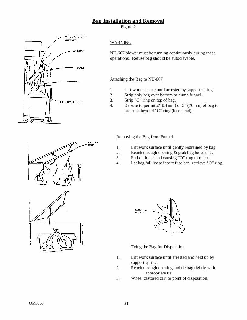
6.4 Bag Installation and Removal (See Figure 2)
Attachment of the bag to the underside of the work surface is easily accomplished when the work surface is raised. Conversely it is easy to also remove the bag for disposal.
OM0053 21
Bag Installation and Removal Figure 2
WARNING
NU-607 blower must be running continuously during these operations. Refuse bag should be autoclavable.
Attaching the Bag to NU-607
1 Lift work surface until arrested by support spring. 2. Strip poly bag over bottom of dump funnel. 3. Strip “O” ring on top of bag.
4. Be sure to permit 2” (51mm) or 3” (76mm) of bag to protrude beyond “O” ring (loose end).
Removing the Bag from Funnel
1. Lift work surface until gently restrained by bag. 2. Reach through opening & grab bag loose end. 3. Pull on loose end causing “O” ring to release. 4. Let bag fall loose into refuse can, retrieve “O” ring.
Tying the Bag for Disposition
1. Lift work surface until arrested and held up by support spring.
2. Reach through opening and tie bag tightly with appropriate tie.
3. Wheel castored cart to point of disposition.
OM0053 22
6.5 Ergonomics
Ergonomics, the study or accommodation of work practices is extremely important for proper cabinet usage and user health and safety. An evaluation of normal work practices should be performed with each user when working in a cabinet. Evaluation criteria should be at a minimum: a. Proper user posture (sitting or standing) b. Effective workzone layout for work practice c. Vision or sightlines For each of the above evaluation criterion, several work aids may be supplied to accommodate the user.
• Ergonomic chair - A six-way articulating seat and back control for personalized adjustment to assure proper user posture. Be sure feet are resting on the floor, chair foot support or foot rest. Also be sure back is fully supported with proper chair adjustments.
• Effective workzone layout - Always prepare your work procedure to minimize reach to avoid neck and shoulder stress and fatigue. Periodic mini-breaks during work practice should be taken to avoid stress and fatigue.
• Vision and sightline - Always prepare your work procedure to eliminate glare and bright reflections on the window. Keep your window clean and sightlines clear to your effective workzone.
6.6 Cleaning Procedures
Cleaning the cabinet is an important function in terms of both containment and sterility. Use the following procedure too effectively clean or surface disinfect the cabinet workzone surfaces.
a. Raise the hinged window to a full-open position, if desired.
b. Apply appropriate disinfecting solution to cabinet surfaces. Most surface disinfectants require a specific contact time depending upon the microbiological agents used within the cabinet. CONSULT APPROPRIATE DISINFECTANT DOCUMENTATION FOR PROPER APPLICATION AND SAFETY PRECAUTIONS.
NOTE: DISINFECTANTS THAT USE CHLORIDES AND HALOGENS WILL CAUSE
DAMAGE TO THE STAINLESS STEEL SURFACES IF LEFT ON FOR LONG PERIODS OF TIME.
c. After the specified contact time, wipe up excess disinfectant. IF THE DISINFECTANT USED
CONTAINS CHLORIDES OR HALOGENS, RE-WIPE ALL SURFACES WITH 70% ALCOHOL OR SIMILAR NON-CORROSIVE ANTI-MICROBIAL AGENT TO PREVENT DAMAGE TO STAINLESS STEEL SURFACES.
OM0053 23
191
ATTENTION ACCOMPANY'S INFORMATION OR IMPORTANT SYMBOL
POTENTIAL ELECTRICAL HAZARD ONLY QUALIFIED PERSON TO ACCESS
188
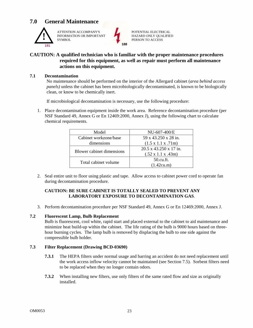
7.0 General Maintenance CAUTION: A qualified technician who is familiar with the proper maintenance procedures
required for this equipment, as well as repair must perform all maintenance actions on this equipment.
7.1 Decontamination
No maintenance should be performed on the interior of the Allergard cabinet (area behind access panels) unless the cabinet has been microbiologically decontaminated, is known to be biologically clean, or know to be chemically inert.
If microbiological decontamination is necessary, use the following procedure:
1. Place decontamination equipment inside the work area. Reference decontamination procedure (per
NSF Standard 49, Annex G or En 12469:2000, Annex J), using the following chart to calculate chemical requirements.
Model NU-607-400/E
Cabinet workzone/base dimensions
59 x 43.250 x 28 in. (1.5 x 1.1 x .71m)
Blower cabinet dimensions 20.5 x 43.250 x 17 in. (.52 x 1.1 x .43m)
Total cabinet volume 50.cu.ft. (1.42cu.m)
2. Seal entire unit to floor using plastic and tape. Allow access to cabinet power cord to operate fan
during decontamination procedure. CAUTION: BE SURE CABINET IS TOTALLY SEALED TO PREVENT ANY LABORATORY EXPOSURE TO DECONTAMINATION GAS.
3. Perform decontamination procedure per NSF Standard 49, Annex G or En 12469:2000, Annex J.
7.2 Fluorescent Lamp, Bulb Replacement Bulb is fluorescent, cool white, rapid start and placed external to the cabinet to aid maintenance and minimize heat build-up within the cabinet. The life rating of the bulb is 9000 hours based on three-hour burning cycles. The lamp bulb is removed by displacing the bulb to one side against the compressible bulb holder.
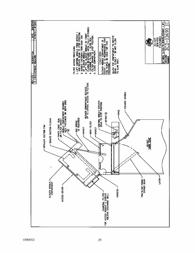
7.3 Filter Replacement (Drawing BCD-03690)
7.3.1 The HEPA filters under normal usage and barring an accident do not need replacement until the work access inflow velocity cannot be maintained (see Section 7.5). Sorbent filters need to be replaced when they no longer contain odors.
7.3.2 When installing new filters, use only filters of the same rated flow and size as originally
installed.
!
OM0053 24
7.3.3 To install the HEPA filter grease the bottom gasket of the filter lightly with silicone grease
and carefully insert. Position the filter frame within the outside walls of the exhaust opening on the top of the hood.
7.3.4 Prefilters should be cleaned or replaced every 3 months or whenever necessary, dependent
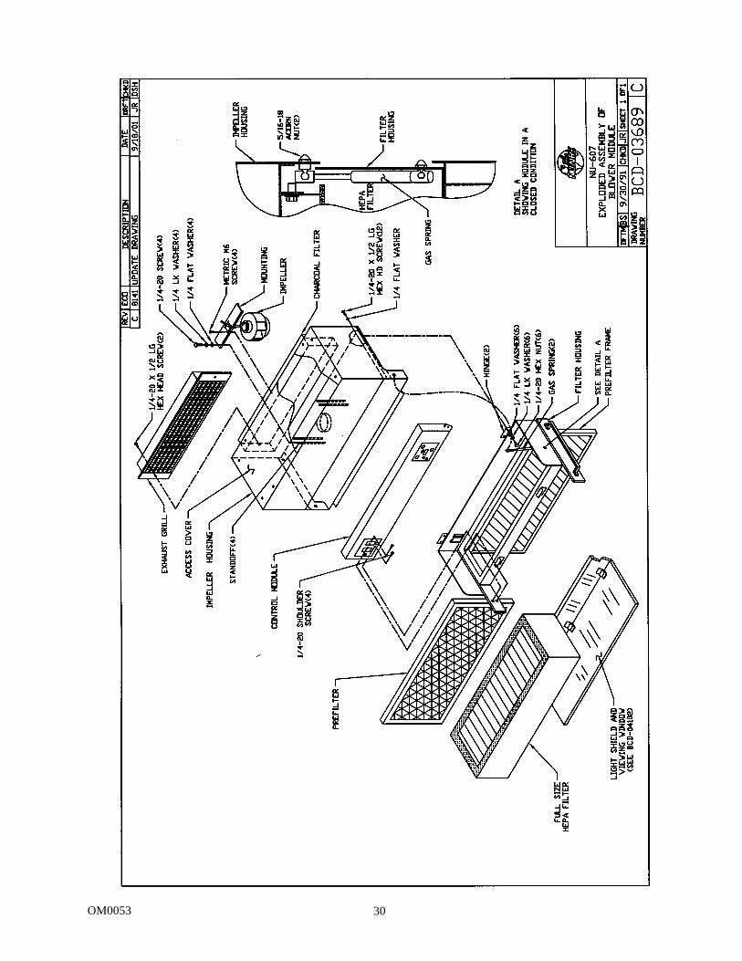
upon excessive particulate loading. 7.4 Motor/Blower Replacement
The motor/blower assembly should never need any preventative maintenance. But in case of a malfunction, the following steps should be taken. Disconnect power or unplug unit before working with any electrical wiring. Motor/blower removal should be done by a qualified technician (see Drawing BCD-03689).
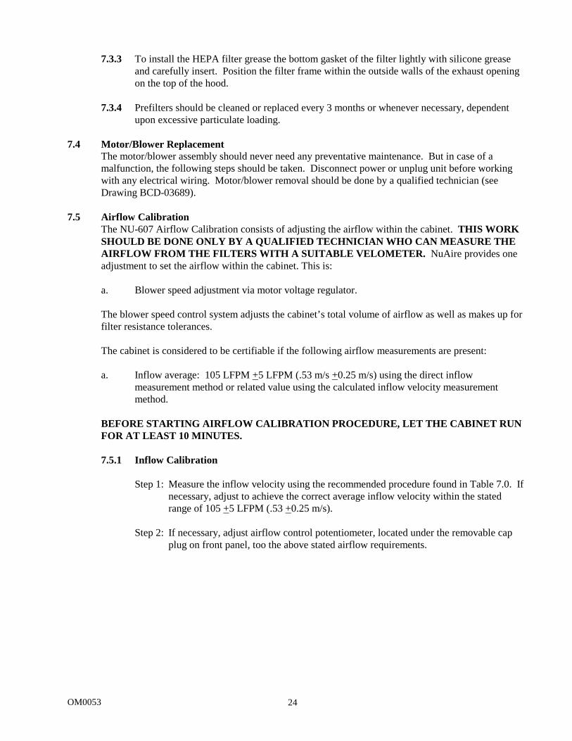
7.5 Airflow Calibration The NU-607 Airflow Calibration consists of adjusting the airflow within the cabinet. THIS WORK SHOULD BE DONE ONLY BY A QUALIFIED TECHNICIAN WHO CAN MEASURE THE AIRFLOW FROM THE FILTERS WITH A SUITABLE VELOMETER. NuAire provides one adjustment to set the airflow within the cabinet. This is: a. Blower speed adjustment via motor voltage regulator. The blower speed control system adjusts the cabinet’s total volume of airflow as well as makes up for filter resistance tolerances. The cabinet is considered to be certifiable if the following airflow measurements are present: a. Inflow average: 105 LFPM +5 LFPM (.53 m/s +0.25 m/s) using the direct inflow
measurement method or related value using the calculated inflow velocity measurement method.
BEFORE STARTING AIRFLOW CALIBRATION PROCEDURE, LET THE CABINET RUN FOR AT LEAST 10 MINUTES. 7.5.1 Inflow Calibration
Step 1: Measure the inflow velocity using the recommended procedure found in Table 7.0. If necessary, adjust to achieve the correct average inflow velocity within the stated range of 105 +5 LFPM (.53 +0.25 m/s).
Step 2: If necessary, adjust airflow control potentiometer, located under the removable cap
plug on front panel, too the above stated airflow requirements.
OM0053 25
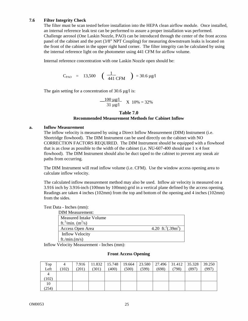
7.6 Filter Integrity Check The filter must be scan tested before installation into the HEPA clean airflow module. Once installed, an internal reference leak test can be performed to assure a proper installation was performed. Challenge aerosol (One Laskin Nozzle, PAO) can be introduced through the center of the front access panel of the cabinet and the port (3/8” NPT Coupling) for measuring downstream leaks is located on the front of the cabinet in the upper right hand corner. The filter integrity can be calculated by using the internal reference light on the photometer using 441 CFM for airflow volume.
Internal reference concentration with one Laskin Nozzle open should be:
The gain setting for a concentration of 30.6 µg/l is:
Table 7.0
Recommended Measurement Methods for Cabinet Inflow a. Inflow Measurement
The inflow velocity is measured by using a Direct Inflow Measurement (DIM) Instrument (i.e. Shortridge flowhood). The DIM Instrument can be used directly on the cabinet with NO CORRECTION FACTORS REQUIRED. The DIM Instrument should be equipped with a flowhood that is as close as possible to the width of the cabinet (i.e. NU-607-400 should use 1 x 4 foot flowhood). The DIM Instrument should also be duct taped to the cabinet to prevent any sneak air paths from occurring. The DIM Instrument will read inflow volume (i.e. CFM). Use the window access opening area to calculate inflow velocity. The calculated inflow measurement method may also be used. Inflow air velocity is measured on a 3.916 inch by 3.916-inch (100mm by 100mm) grid in a vertical plane defined by the access opening. Readings are taken 4 inches (102mm) from the top and bottom of the opening and 4 inches (102mm) from the sides.
Test Data - Inches (mm):
DIM Measurement:
Inflow Velocity Measurement - Inches (mm):
Front Access Opening
Top Left
4 (102)
7.916 (201)
11.832 (301)
15.748 (400)
19.664 (500)
23.580 (599)
27.496 (698)
31.412 (798)
35.328 (897)
39.250 (997)
4 (102)
10 (254)
CPAO = 13,500 ( _1 _ 441 CFM ) = 30.6 µg/l
__100 µg/l_ 31 µg/l X 10% = 32%
Measured Intake Volume ft.3/min. (m3/s) Access Open Area 4.20 ft.2(.39m2) Inflow Velocity ft./min.(m/s)

OM0053 26
Number of Readings Average Velocity ft./min.(m/s)

OM0053 27
8.0 Polycarbonate Material Compatibility 8.1 Polycarbonate sheet is resistant at 70° to these chemicals. Amyl alcohol Chromic acid (20%) Lactic acid (20%) Potassium bromate Sodium chloride Aluminum chloride Citric acid (40%) Magnesium chloride Potassium bromide Sodium hypochlorite Aluminum sulphate Copper chloride Magnesium sulphate Potassium nitrate Sodium sulphate Ammonium chloride Copper sulphate Maganese sulphate Potassium perchlorate Stannous chloride Ammonium nitrate Formic acid (10%) Mercuric chloride Potassium permanganate Sulfur Ammonium sulphate Formalin (30%) Nickel sulphate Potassium persulphate Sulfuric acid (>10%) Antimony trichloride Glycerine Nitric acid (10%) Potassium sulphate Sulfuric acid (50%) Arsenic acid Heptane Nitric acid (20%) Silicone oil Tartaric acid (30%) Butyl alcohol Hydrochloric acid
(10%) Oleic acid Silver nitrate Zinc chloride
Calcium nitrate Hydrogen peroxide (30%)
Oxalic acid Sodium bicarbonate Zinc sulphate
Chlorinated Lime Paste Hydrofluoric acid (10%) Pentane Sodium bisulphate Chrome alum Isopropyl alcohol (70%) Phosphoric acid (10%) Sodium carbonate 8.2 Polycarbonate sheet is not resistant to these chemicals. Acetaldehyde Carbon tetrachloride Ethane tetrachloride Phenol Acetic acid (conc.) Carbon disulfide Ethylamine Phosphorous hydroxy chloride Acetone Carbolic acid Ethylene dichloride Phosphorous trichloride Acrylonitrile Caustic potash solution (5%) Ethyl ether Proplonic acid Ammonia Caustic soda solution (5%) Ethylene chlorohydrin Pyridine Ammonium fluoride Chloroform Formic acid (conc.) Sodium sulfide Ammonium hydroxide Chlorothene Freon (refrigerant & propellant) Sodium hydroxide Ammonium sulfide Chlorobenzene Gasoline Sodium nitrate Benzene Cresol Lacquer thinner Sylfuric acid (1%) Benzoic acid Cutting oils Methyl alcohol Tetrahydronaphthalene Benzyl alcohol Cyclo hexanone Methylene chloride Thiophene Brake fluid Cyclohexene Nitrobezene Toluene Bromobenzene Dimethyl formamide Nurocellulose lacquer Turpentine Butylic acid Dioxane Ozone Xylene
OM0053 28
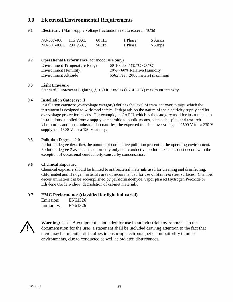
9.0 Electrical/Environmental Requirements 9.1 Electrical: (Main supply voltage fluctuations not to exceed +10%)
NU-607-400 115 VAC, 60 Hz, 1 Phase, 5 Amps NU-607-400E 230 VAC, 50 Hz, 1 Phase, 5 Amps
9.2 Operational Performance (for indoor use only)
Environment Temperature Range: 60°F - 85°F (15°C - 30°C) Environment Humidity: 20% - 60% Relative Humidity Environment Altitude 6562 Feet (2000 meters) maximum
9.3 Light Exposure
Standard Fluorescent Lighting @ 150 ft. candles (1614 LUX) maximum intensity. 9.4 Installation Category: II
Installation category (overvoltage category) defines the level of transient overvoltage, which the instrument is designed to withstand safely. It depends on the nature of the electricity supply and its overvoltage protection means. For example, in CAT II, which is the category used for instruments in installations supplied from a supply comparable to public means, such as hospital and research laboratories and most industrial laboratories, the expected transient overvoltage is 2500 V for a 230 V supply and 1500 V for a 120 V supply.
9.5 Pollution Degree: 2.0
Pollution degree describes the amount of conductive pollution present in the operating environment. Pollution degree 2 assumes that normally only non-conductive pollution such as dust occurs with the exception of occasional conductivity caused by condensation.
9.6 Chemical Exposure
Chemical exposure should be limited to antibacterial materials used for cleaning and disinfecting. Chlorinated and Halogen materials are not recommended for use on stainless steel surfaces. Chamber decontamination can be accomplished by paraformaldehyde, vapor phased Hydrogen Peroxide or Ethylene Oxide without degradation of cabinet materials.
9.7 EMC Performance (classified for light industrial)
Emission: EN61326 Immunity: EN61326
Warning: Class A equipment is intended for use in an industrial environment. In the documentation for the user, a statement shall be included drawing attention to the fact that there may be potential difficulties in ensuring electromagnetic compatibility in other environments, due to conducted as well as radiated disturbances.
!
OM0053 29
OM0053 30
OM0053 31
OM0053 32