Embed Size (px)
Citation preview
1
Laboratory scale sewerage system
for detection of contaminants in
wastewater
Victor Benavides
Andreas Forsman
Alicja Malik
LiangFu Wang
Final Report
European Project Semester, Spring 2013
Vaasa 2013
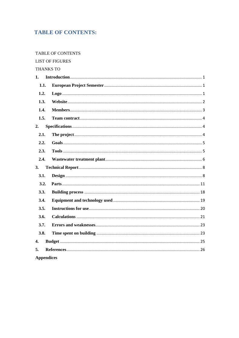
TABLE OF CONTENTS:
TABLE OF CONTENTS
LIST OF FIGURES
THANKS TO
1. Introduction ....................................................................................................................... 1
1.1. European Project Semester ........................................................................................ 1
1.2. Logo .............................................................................................................................. 1
1.3. Website ......................................................................................................................... 2
1.4. Members ....................................................................................................................... 3
1.5. Team contract .............................................................................................................. 4
2. Specifications ..................................................................................................................... 4
2.1. The project ................................................................................................................... 4
2.2. Goals ............................................................................................................................. 5
2.3. Tools ............................................................................................................................. 5
2.4. Wastewater treatment plant ....................................................................................... 6
3. Technical Report ............................................................................................................... 8
3.1. Design ........................................................................................................................... 8
3.2. Parts ............................................................................................................................ 11
3.3. Building process ........................................................................................................ 18
3.4. Equipment and technology used .............................................................................. 19
3.5. Instructions for use.................................................................................................... 20
3.6. Calculations ............................................................................................................... 21
3.7. Errors and weaknesses .............................................................................................. 23
3.8. Time spent on building ............................................................................................. 23
4. Budget .............................................................................................................................. 25
5. References ........................................................................................................................ 26
Appendices
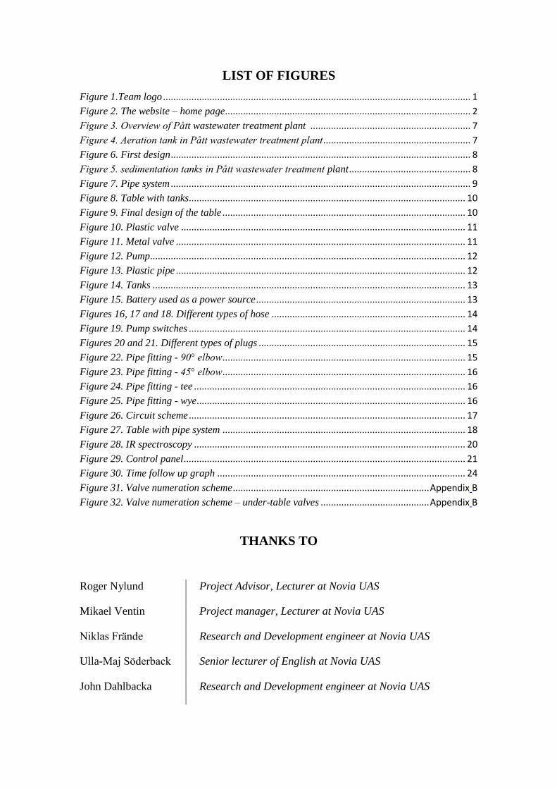
LIST OF FIGURES
Figure 1.Team logo ....................................................................................................................... 1
Figure 2. The website – home page ............................................................................................... 2
Figure 3. Overview of Pått wastewater treatment plant .............................................................. 7
Figure 4. Aeration tank in Pått wastewater treatment plant ......................................................... 7
Figure 6. First design .................................................................................................................... 8
Figure 5. sedimentation tanks in Pått wastewater treatment plant ............................................... 8
Figure 7. Pipe system .................................................................................................................... 9
Figure 8. Table with tanks........................................................................................................... 10
Figure 9. Final design of the table .............................................................................................. 10
Figure 10. Plastic valve .............................................................................................................. 11
Figure 11. Metal valve ................................................................................................................ 11
Figure 12. Pump .......................................................................................................................... 12
Figure 13. Plastic pipe ................................................................................................................ 12
Figure 14. Tanks ......................................................................................................................... 13
Figure 15. Battery used as a power source ................................................................................. 13
Figures 16, 17 and 18. Different types of hose ........................................................................... 14
Figure 19. Pump switches ........................................................................................................... 14
Figures 20 and 21. Different types of plugs ................................................................................ 15
Figure 22. Pipe fitting - 90° elbow .............................................................................................. 15
Figure 23. Pipe fitting - 45° elbow .............................................................................................. 16
Figure 24. Pipe fitting - tee ......................................................................................................... 16
Figure 25. Pipe fitting - wye........................................................................................................ 16
Figure 26. Circuit scheme ........................................................................................................... 17
Figure 27. Table with pipe system .............................................................................................. 18
Figure 28. IR spectroscopy ......................................................................................................... 20
Figure 29. Control panel ............................................................................................................. 21
Figure 30. Time follow up graph ................................................................................................ 24
Figure 31. Valve numeration scheme ............................................................................ Appendix B
Figure 32. Valve numeration scheme – under-table valves .......................................... Appendix B
THANKS TO
Roger Nylund Project Advisor, Lecturer at Novia UAS
Mikael Ventin Project manager, Lecturer at Novia UAS
Niklas Frände Research and Development engineer at Novia UAS
Ulla-Maj Söderback Senior lecturer of English at Novia UAS
John Dahlbacka Research and Development engineer at Novia UAS
1
1. Introduction
1.1. European Project Semester
European Project Semester is a program run by ten countries throughout Europe.
There are eleven universities participating in this program. EPS is addressed to third
year university students, especially engineers.
EPS is designed to prepare students with necessary skills to face the challenges of
today’s world. Students are grouped to create international and interdisciplinary teams
consisting of 3-6 members. Sometimes teams are collaborating with commercial
businesses and industries. During this project students learn that they are responsible for
their work. They also develop intercultural competences and improve their
communication and interpersonal skills. One of the most important things for students is
to learn how to work with international people and to share different points of view. /3/
1.2. Logo
To enhance the group coherence and presentation several logo designs were created.
The following one was chosen.
Figure 1.Team logo

2
The team logo is a combination of a water drop, which symbolizes the practical part of
the project (the building of the pipe system) and the name Mare Purum which refers to
the aim and application of the project.
1.3. Website
A website was created in order to share information about the project with everyone
interested in it. It was programmed by HTML, CSS and basic JavaScript. The site of the
internet is as follows: http://eps.novia.fi/2013/marepurum.
The website contains eight subpages. They are described below.
Home page: As can be seen below, it is a “welcome” page; the “news” part will be kept
up to date until the end of the project. The “road sign” image at the bottom directs a
viewer to the “download” page.
Figure 2. The website – home page
3
Download page: here the documents from team meetings - “agendas and minutes” as
well as presentations and reports can be found
EPS page: this page contains information about the EPS project itself. The link placed
on this site will take the viewer to the official site of the European Project Semester.
EPS 2013 page: describes the project
GALLERY page: this page contains a few photos of team members during work
MEMBERS page: information about the members of EPS group can be found here
CONTACT page: contains contact information about the team
VIDEO page: here a 3D photo album and a video can be found
1.4. Members
The EPS group in Vaasa during spring term 2013 consisted of two exchange students
and two degree students. Each member of the team was from a different country and
had different skills and abilities.
Name: Víctor Benavides
Date of birth: 27-01-1990
Country: Spain, Barcelona
University: Universitat Politècnica de Catalunya
Degree program: Electrical Engineering
4
Name: Andreas Forsman
Date of birth: 11-01-1986
Country: Finland, Munsala
University: Novia University of Applied Sciences
Degree: Environmental Engineering
Name: Wang Liangfu
Date of birth: 23-01-1989
Country: China
University: Novia University of Applied Sciences
Degree program: Electrical Engineering
Name: Alicja Malik
Date of birth: 12-03-1991
Country: Poland, Lodz
University: Lodz University of Technology
Degree program: Engineering in Biotechnology
1.5. Team contract
To establish some basic rules and responsibilities inside the project group a team
contract was created. It was written in order to increase the effectiveness of team work
during the project and to ensure the team success. (appendix A)
2. Specifications
2.1. The Project
Mare Purum is a project focusing on studying and improving biological wastewater
facilities in the Botnia-Atlantica region. This EPS project has been focused on
5
the wastewater treatment facility at Pått. This facility uses biological treatment as one
step of the cleaning process, which is very sensitive. It would be good for facility
workers to have the ability to assess when the water is contaminated. To discover these
contaminations a vibrational spectroscopy can be used. /5/
The task of this project was to design, construct and test an experimental facility in
which the usability of vibrational spectroscopy application for contamination
measurement can be examined. This task is not focused on using vibrational
spectroscopy, but rather on providing the Mare Purum project with the device needed to
test it.
2.2. Goals
First of all it is necessary to specify what the targets of the EPS project are and
determine or define a useful plan to achieve the main aim. The main aim is to build
a facility that simulates the conditions at a wastewater treatment plant.
2.3. Tools
To be successful in the EPS Project, Novia University of Applied Sciences provided the
team with necessary tools. The most often used ones are the following:
Internet
Lectures
Weekly meetings
MS Project
At the beginning of this project, lecturers gave different lectures about how to set up the
project and the main steps that should be followed.
The first days of the project were dedicated to getting to know the university and the
classmates. Mr David Swetnam from England came to Vaasa and explained to the EPS
group how team building works and what kind of personality each member should have
to be successful in the project. In addition, Mr Nelson showed how the Tritonia library
works. Mr Mikael Ventin gave several lectures on Project Management.
6
Mr Roger Nylund showed the team different meeting techniques. Mr John Dahlbacka
and Mr Niklas Frände played important roles because they provided the team with a lot
of information about the project. Their opinions were crucial at the beginning of the
project. The main source used in this EPS project was Internet. However, the project
meetings with Mr Frände were also important. During these meetings the team members
were able to discuss the mistakes and find solutions for them.
2.4. Wastewater treatment plant
On Monday, 18 March 2013, the team went on a trip to the local wastewater treatment
facility named Pått (Påttska Reningsverket). It is situated close to the sea on Palosaari,
one of Vaasa’s districts.
Pått wastewater treatment plant cleans wastewater not only from Vaasa, but also from
parts of the municipalities of Mustasaari and Maalahti. After that process clean water is
led out into the sea. 6 – 7 million m3 of wastewater is collected annually from those
areas.
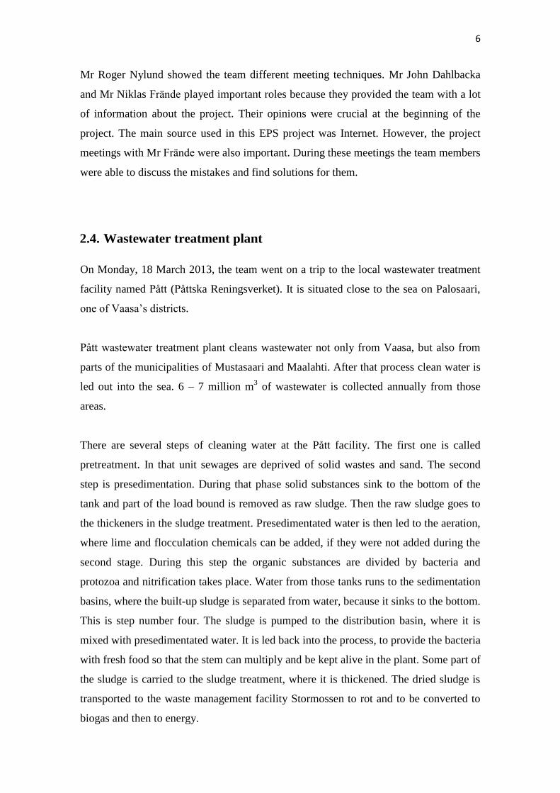
There are several steps of cleaning water at the Pått facility. The first one is called
pretreatment. In that unit sewages are deprived of solid wastes and sand. The second
step is presedimentation. During that phase solid substances sink to the bottom of the
tank and part of the load bound is removed as raw sludge. Then the raw sludge goes to
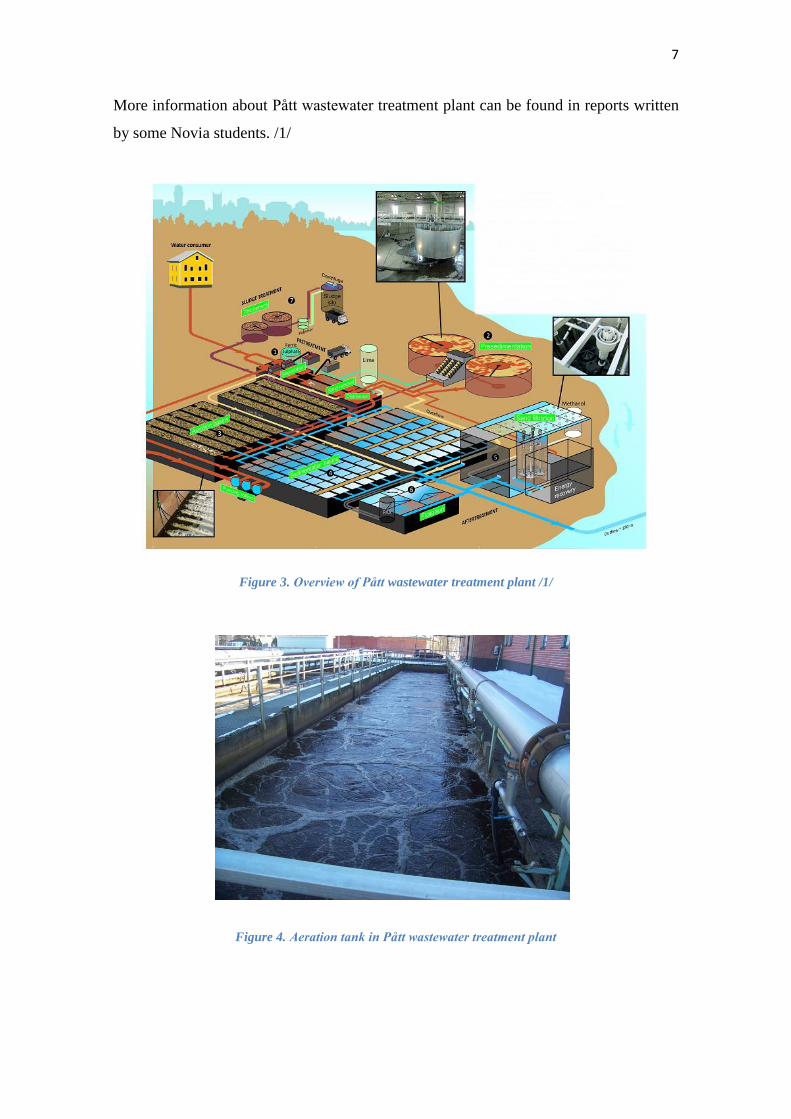
the thickeners in the sludge treatment. Presedimentated water is then led to the aeration,
where lime and flocculation chemicals can be added, if they were not added during the
second stage. During this step the organic substances are divided by bacteria and
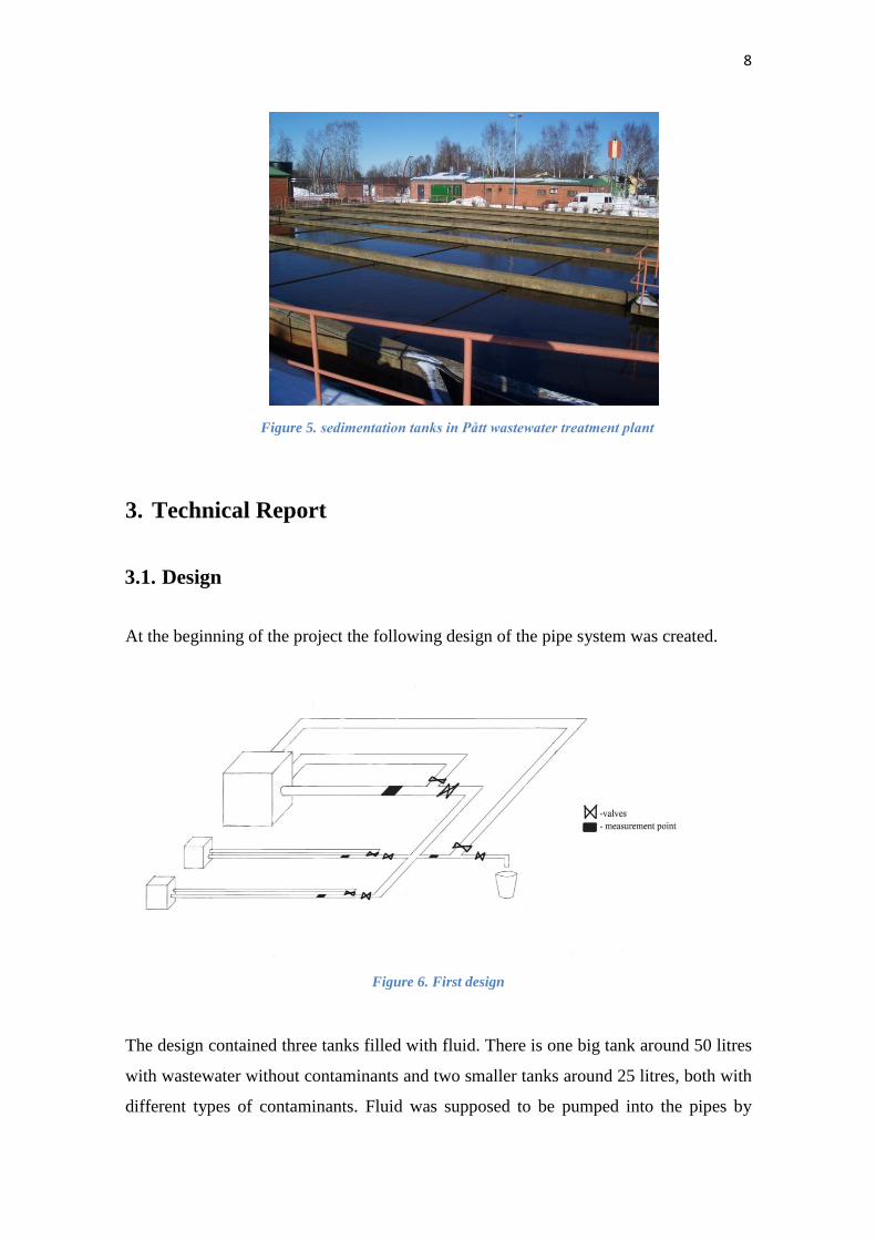
protozoa and nitrification takes place. Water from those tanks runs to the sedimentation
basins, where the built-up sludge is separated from water, because it sinks to the bottom.
This is step number four. The sludge is pumped to the distribution basin, where it is
mixed with presedimentated water. It is led back into the process, to provide the bacteria
with fresh food so that the stem can multiply and be kept alive in the plant. Some part of
the sludge is carried to the sludge treatment, where it is thickened. The dried sludge is
transported to the waste management facility Stormossen to rot and to be converted to
biogas and then to energy.
7
More information about Pått wastewater treatment plant can be found in reports written
by some Novia students. /1/
Figure 3. Overview of Pått wastewater treatment plant /1/
Figure 4. Aeration tank in Pått wastewater treatment plant
8
3. Technical Report
3.1. Design
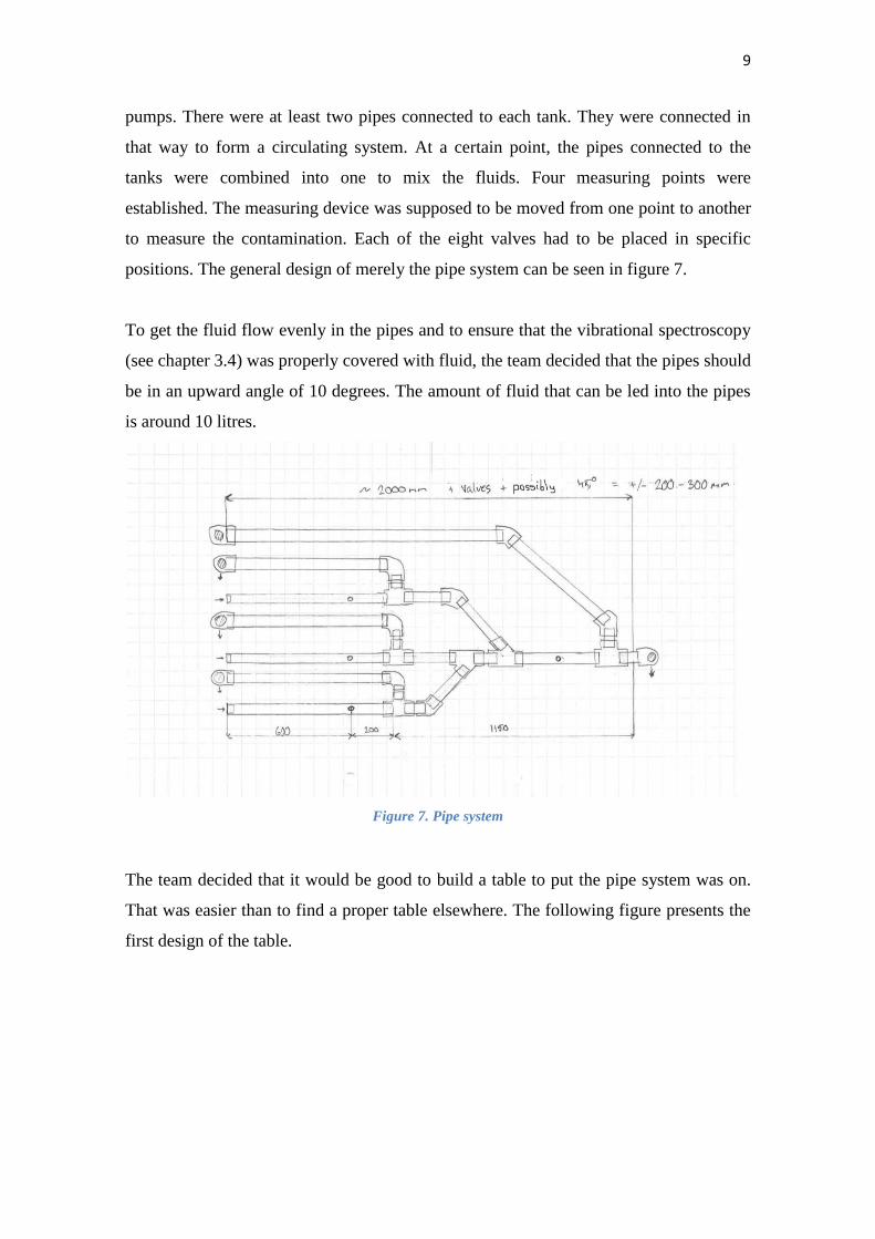
At the beginning of the project the following design of the pipe system was created.
Figure 6. First design
The design contained three tanks filled with fluid. There is one big tank around 50 litres
with wastewater without contaminants and two smaller tanks around 25 litres, both with
different types of contaminants. Fluid was supposed to be pumped into the pipes by
Figure 5. sedimentation tanks in Pått wastewater treatment plant
9
pumps. There were at least two pipes connected to each tank. They were connected in
that way to form a circulating system. At a certain point, the pipes connected to the
tanks were combined into one to mix the fluids. Four measuring points were
established. The measuring device was supposed to be moved from one point to another
to measure the contamination. Each of the eight valves had to be placed in specific
positions. The general design of merely the pipe system can be seen in figure 7.
To get the fluid flow evenly in the pipes and to ensure that the vibrational spectroscopy
(see chapter 3.4) was properly covered with fluid, the team decided that the pipes should
be in an upward angle of 10 degrees. The amount of fluid that can be led into the pipes
is around 10 litres.
Figure 7. Pipe system
The team decided that it would be good to build a table to put the pipe system was on.
That was easier than to find a proper table elsewhere. The following figure presents the
first design of the table.
10
Figure 8. Table with tanks
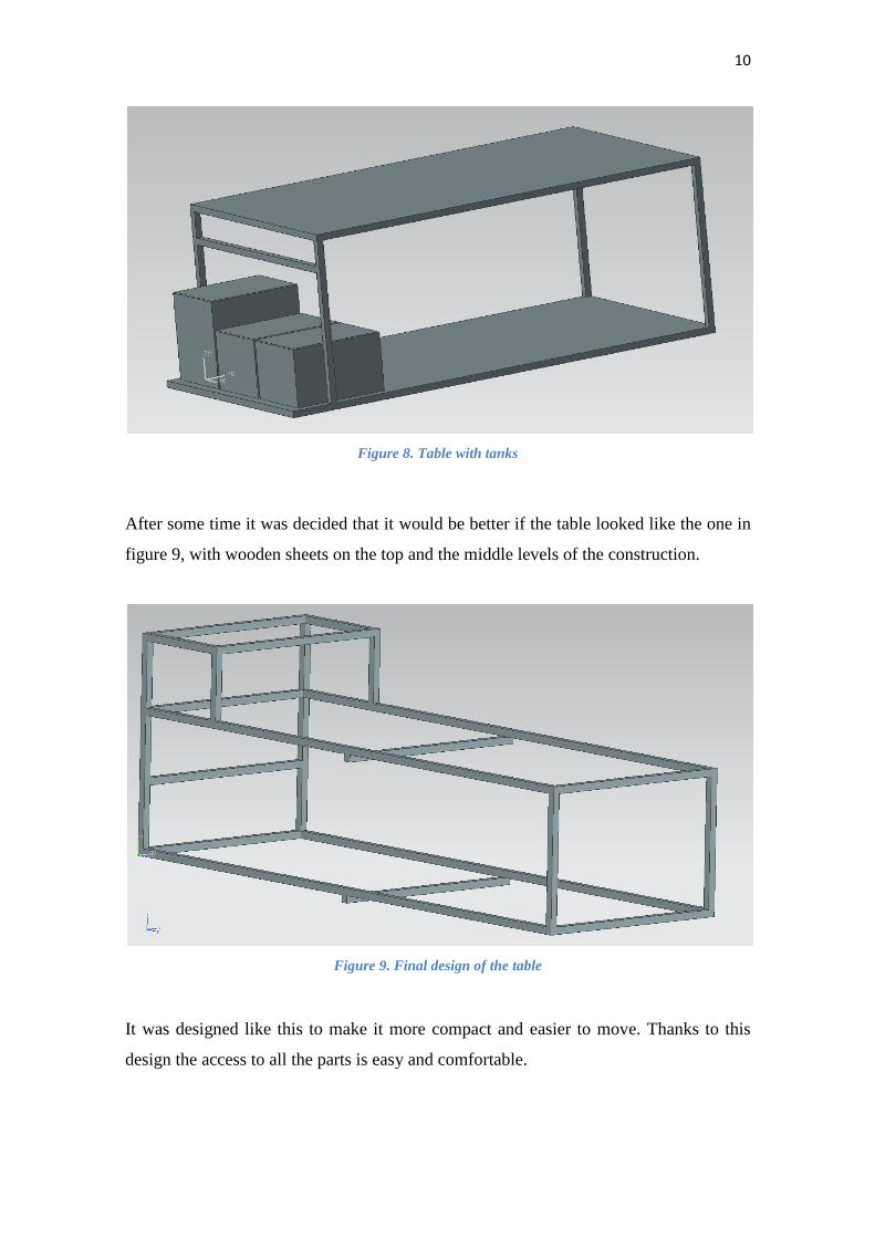
After some time it was decided that it would be better if the table looked like the one in
figure 9, with wooden sheets on the top and the middle levels of the construction.
Figure 9. Final design of the table
It was designed like this to make it more compact and easier to move. Thanks to this
design the access to all the parts is easy and comfortable.
11
The design of the pipe system changed only a little bit since the first design. The
returning pipes were replaced by hoses. In the lowest part of the pipe system plugs were
added in order to enable an easy removal of the fluid.
3.2. Parts
The construction consists of several parts. Each one is described below:
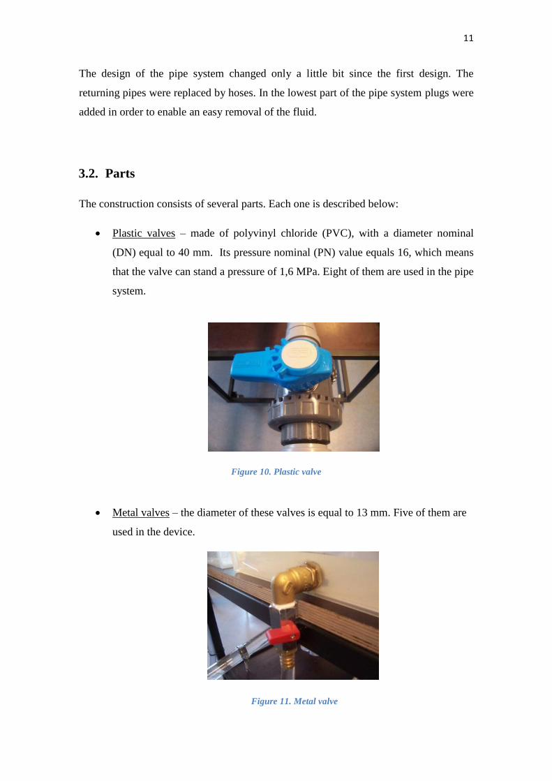
Plastic valves – made of polyvinyl chloride (PVC), with a diameter nominal
(DN) equal to 40 mm. Its pressure nominal (PN) value equals 16, which means
that the valve can stand a pressure of 1,6 MPa. Eight of them are used in the pipe
system.
Figure 10. Plastic valve
Metal valves – the diameter of these valves is equal to 13 mm. Five of them are
used in the device.
Figure 11. Metal valve
12
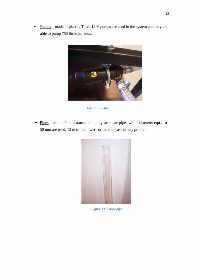
Pumps – made of plastic. Three 12 V pumps are used in the system and they are
able to pump 750 litres per hour.
Figure 12. Pump
Pipes – around 9 m of transparent, polycarbonate pipes with a diameter equal to
50 mm are used. 12 m of them were ordered in case of any problem.
Figure 13. Plastic pipe
13
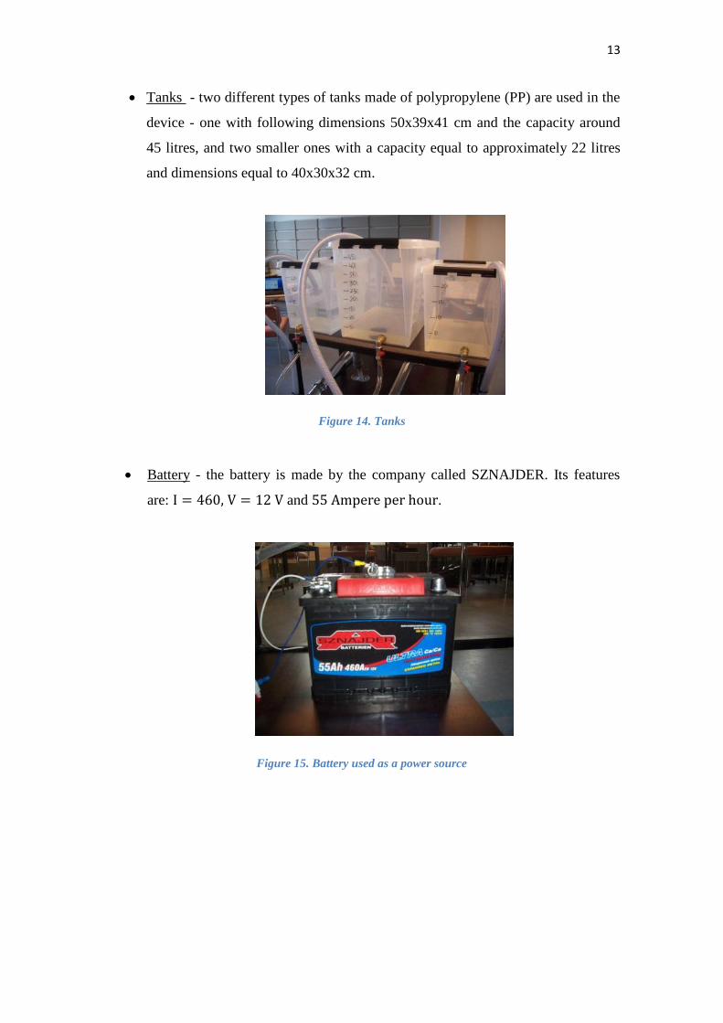
Tanks - two different types of tanks made of polypropylene (PP) are used in the
device - one with following dimensions 50x39x41 cm and the capacity around
45 litres, and two smaller ones with a capacity equal to approximately 22 litres
and dimensions equal to 40x30x32 cm.
Figure 14. Tanks
Battery - the battery is made by the company called SZNAJDER. Its features
are: and .
Figure 15. Battery used as a power source
14
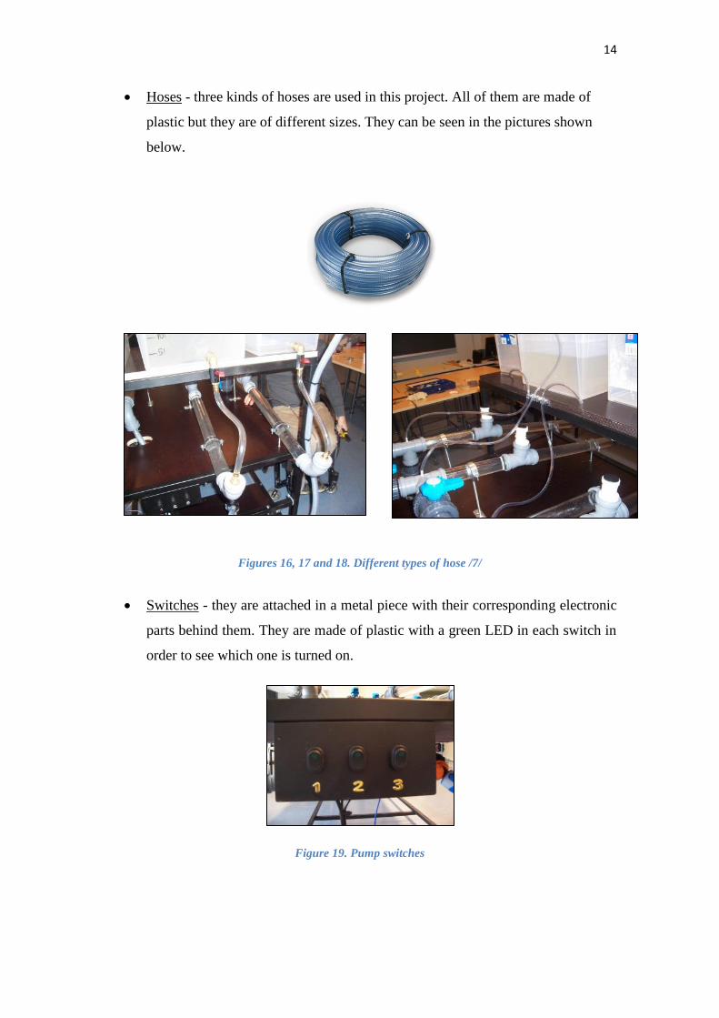
Hoses - three kinds of hoses are used in this project. All of them are made of
plastic but they are of different sizes. They can be seen in the pictures shown
below.
Figures 16, 17 and 18. Different types of hose /7/
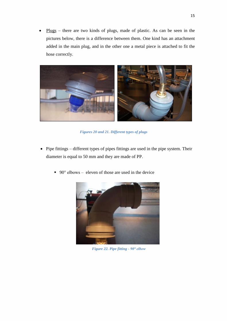
Switches - they are attached in a metal piece with their corresponding electronic
parts behind them. They are made of plastic with a green LED in each switch in
order to see which one is turned on.
Figure 19. Pump switches
15
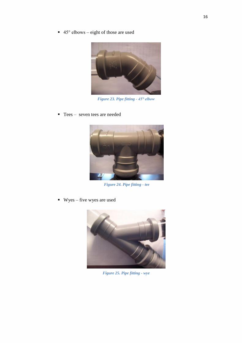
Plugs – there are two kinds of plugs, made of plastic. As can be seen in the
pictures below, there is a difference between them. One kind has an attachment
added in the main plug, and in the other one a metal piece is attached to fit the
hose correctly.
Figures 20 and 21. Different types of plugs
Pipe fittings – different types of pipes fittings are used in the pipe system. Their
diameter is equal to 50 mm and they are made of PP.
90° elbows – eleven of those are used in the device
Figure 22. Pipe fitting - 90° elbow
16
45° elbows – eight of those are used
Tees – seven tees are needed
Wyes – five wyes are used
Figure 23. Pipe fitting - 45° elbow
Figure 24. Pipe fitting - tee
Figure 25. Pipe fitting - wye
17
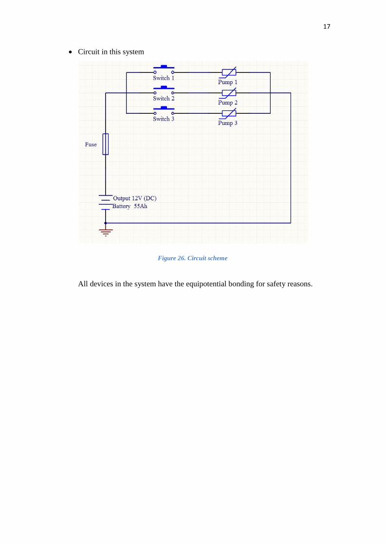
Circuit in this system
Figure 26. Circuit scheme
All devices in the system have the equipotential bonding for safety reasons.
18
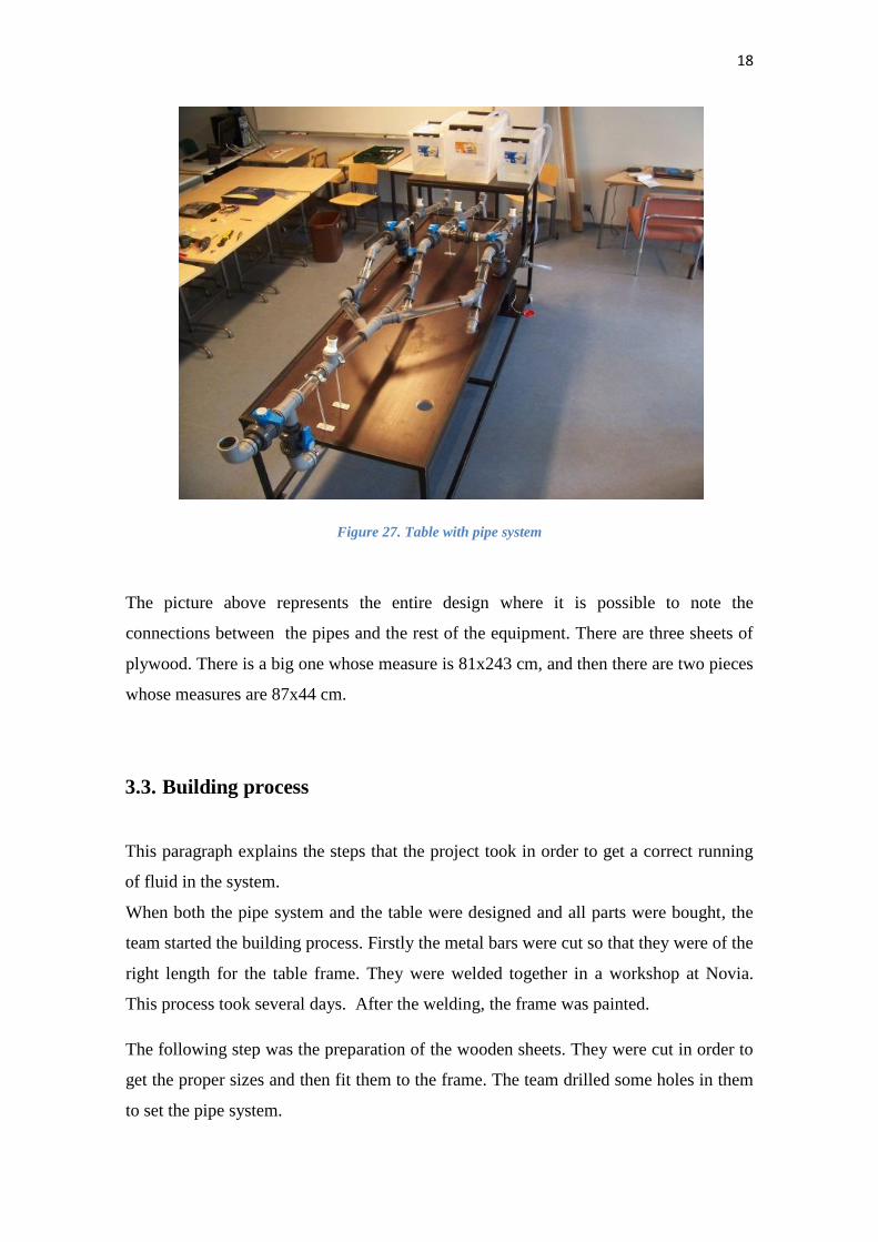
Figure 27. Table with pipe system
The picture above represents the entire design where it is possible to note the
connections between the pipes and the rest of the equipment. There are three sheets of
plywood. There is a big one whose measure is 81x243 cm, and then there are two pieces
whose measures are 87x44 cm.
3.3. Building process
This paragraph explains the steps that the project took in order to get a correct running
of fluid in the system.
When both the pipe system and the table were designed and all parts were bought, the
team started the building process. Firstly the metal bars were cut so that they were of the
right length for the table frame. They were welded together in a workshop at Novia.
This process took several days. After the welding, the frame was painted.
The following step was the preparation of the wooden sheets. They were cut in order to
get the proper sizes and then fit them to the frame. The team drilled some holes in them
to set the pipe system.
19
When attaching the system to the table, and the hoses, tanks and electronic parts were
connected, it had to be tested to see that the valves were attached correctly to the pipes.
A special kind of glue was used to avoid fluid leakage. During the building process all
safety precautions were taken.
3.4. Equipment and technology used
In this section the equipment and the technology that were used during the project are
explained.
Vibrational Spectroscopy
Vibrational spectroscopy can be divided into two types of spectroscopies.
The difference between these two is the intensitivity of the wavelengths. Near-Infrared
spectroscopy (NIRS) is one of the vibrational spectroscopies that analyses the presence
of different functional groups in chemical compounds in a wavelength between
700-2500 nm, and IR spectroscopy between 2500-5000 nm. Vibrational spectroscopy is
often used by chemists. This method is based on different IR frequencies of a
researched sample.
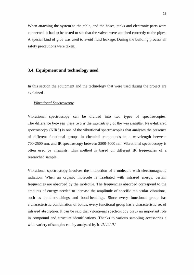
Vibrational spectroscopy involves the interaction of a molecule with electromagnetic
radiation. When an organic molecule is irradiated with infrared energy, certain
frequencies are absorbed by the molecule. The frequencies absorbed correspond to the
amounts of energy needed to increase the amplitude of specific molecular vibrations,
such as bond-stretchings and bond-bendings. Since every functional group has
a characteristic combination of bonds, every functional group has a characteristic set of
infrared absorption. It can be said that vibrational spectroscopy plays an important role
in compound and structure identifications. Thanks to various sampling accessories a
wide variety of samples can by analyzed by it. /2/ /4/ /6/
20
Figure 28. IR spectroscopy /8/
3.5. Instructions for use
The pipe system is built to be able to run three tests at the same time. If wanted, these
three tests can be mixed into one. Before a test is started, the tanks must be filled with
the proper amount of fluid. The maximum amount of fluid that can be used is 50 litres
and can be divided into desired amounts. The pipe system uses self-pressure to get the
fluids into the pipes. Each circuit has its own returning pipe, which is connected to
a pump that pumps the fluid back to the tank. Circuits 1 and 3 have their own pumps,
but circuits 2 and 4 share one pump. In case of running two or three tests into one, the
returning pipes in the desired circuits should be closed, and the valve that leads to
circuit 4 should be opened. After this is done, it is necessary to close the valve of the
returning pipe in circuit 2 and open the valve from circuit 4. It is important to do this
because otherwise the fluid will start to go in the wrong direction.
There are four measuring points in the circuits where the NIR-probe can be inserted.
In case of changing the measuring point during a test, it is necessary to close the valve
at the tank and run the returning pump until the pressure in the circuit is gone.
21
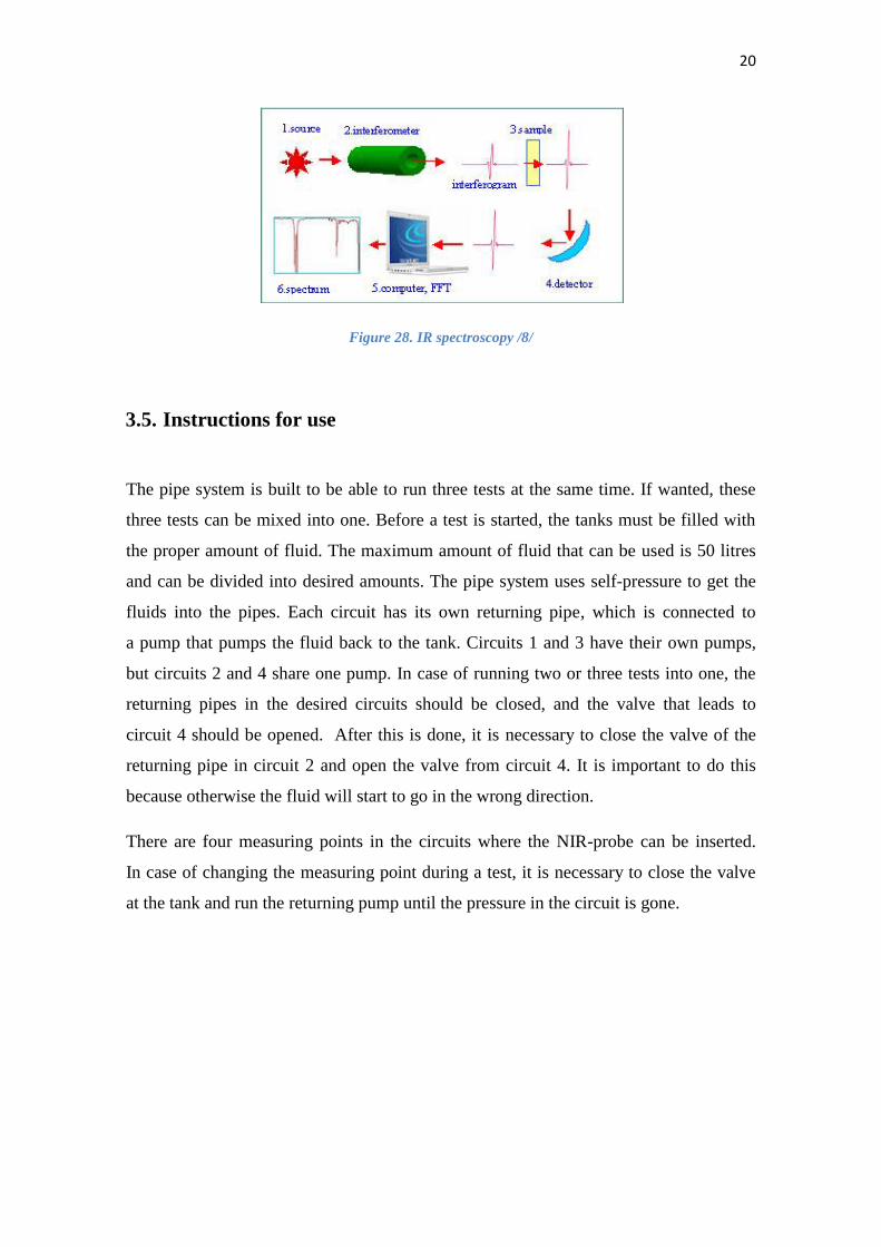
Figure 29. Control panel
Step-by-step instructions for use can be found at the end of this report in appendix B.
3.6. Calculations
During the testing process the following calculations were made.
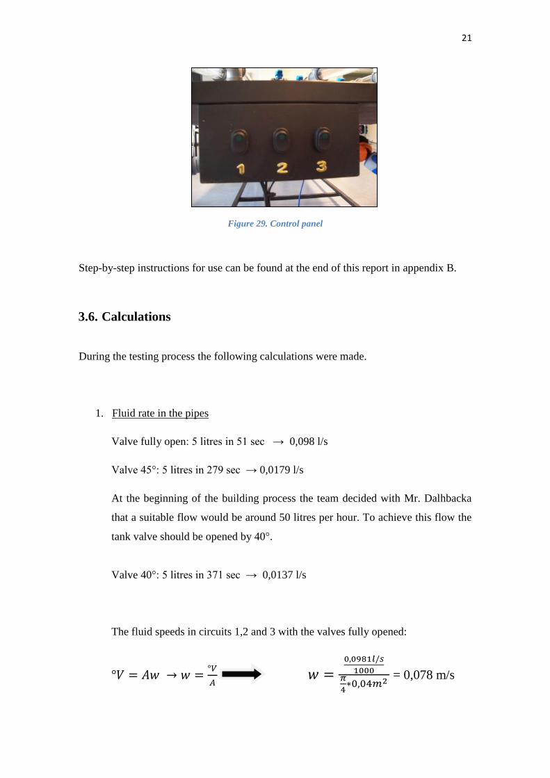
1. Fluid rate in the pipes
Valve fully open: 5 litres in 51 sec → 0,098 l/s
Valve 45°: 5 litres in 279 sec → 0,0179 l/s
At the beginning of the building process the team decided with Mr. Dalhbacka
that a suitable flow would be around 50 litres per hour. To achieve this flow the
tank valve should be opened by 40°.
Valve 40°: 5 litres in 371 sec → 0,0137 l/s
The fluid speeds in circuits 1,2 and 3 with the valves fully opened:
= 0,078 m/s
22
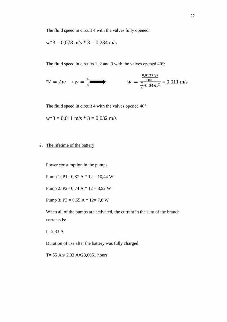
The fluid speed in circuit 4 with the valves fully opened:
w*3 = 0,078 m/s * 3 = 0,234 m/s
The fluid speed in circuits 1, 2 and 3 with the valves opened 40°:
= 0,011 m/s
The fluid speed in circuit 4 with the valves opened 40°:
w*3 = 0,011 m/s * 3 = 0,032 m/s
2. The lifetime of the battery
Power consumption in the pumps
Pump 1: P1= 0,87 A * 12 = 10,44 W
Pump 2: P2= 0,74 A * 12 = 8,52 W
Pump 3: P3 = 0,65 A * 12= 7,8 W
When all of the pumps are activated, the current in the sum of the branch
currents is:
I= 2,33 A
Duration of use after the battery was fully charged:
T= 55 Ah/ 2,33 A=23,6051 hours
23
3.7. Errors and weaknesses
During this project there have been several problems that the team had to overcome,
such as leakage, problem with lack of air in the system, and fluid removal.
Leakages were the most common problem, due to the fact that parts were not glued
correctly.
However, this problem was solved by adding more glue called Sikaflex or Loctite.
Another problem that caused delays in the advancement of the project was the air
ventilation. It was solved with hoses that were attached to the tees. After some tests it
was discovered that removal of the fluid was a problem that also had to be solved.
It was done by a couple of plugs in the lowest points in the system.
3.8. Time spent on building
The building of the device took around two months. During this time the team was
searching for parts, connecting them and testing the system. The obtaining of the parts
was the most time consuming task. Many of the parts had to be specially ordered and
the team had to wait and even pause the building for some time and focus on other tasks
during the waiting time. During the whole building process the team has been searching
for more parts, i.e. the total time spent on searching for parts is about 20 days during
two months. The actual building of the pipe system took about 15 days. The table took
about three days to build, the fitting of the pipes and valves took about five days and the
assembling of small parts like the tank valves and the hoses took about four days. The
remaining three days of those 15 building days were spent on glueing all the parts
correctly, so that the pipe system would not have any leakage within the splices. After
the table and the pipe system were finished we spent about five days testing the system
to get it work like it should.
Assuming that each team member spent around 6 to 8 hours per day working on the
pipe system gives a total of 240 to 340 hours per member. Accordingly, the total time
spent on building is 960 to 1280 hours for all four members in the team.
24
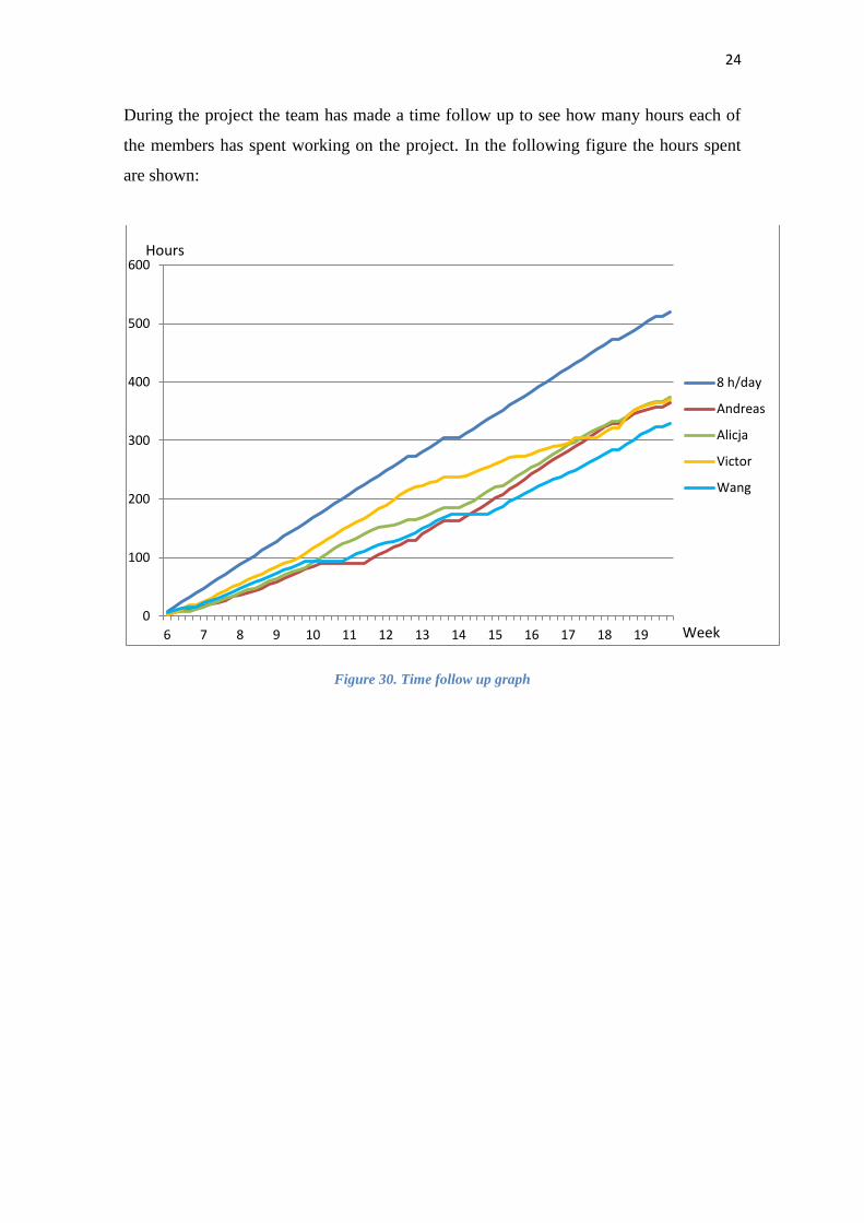
During the project the team has made a time follow up to see how many hours each of
the members has spent working on the project. In the following figure the hours spent
are shown:
Figure 30. Time follow up graph
0
100
200
300
400
500
600
6 7 8 9 10 11 12 13 14 15 16 17 18 19
8 h/day
Andreas
Alicja
Victor
Wang
Hours
Week
25
4. Budget
The entire project was financed by Mare Purum, whose main financiers are the Regional
Council of Ostrobothnia, the Botnia-Atlantica programme and Region Västerbotten. /5/
More expensive parts were bought by Mr. Dahlbacka, the rest of them were bought by
the team members, who got a refund of the money they spent. These are the
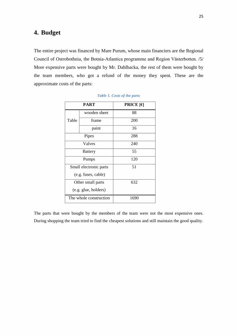
approximate costs of the parts:
Table 1. Costs of the parts
PART PRICE [€]
Table
wooden sheet 88
frame 200
paint 16
Pipes 288
Valves 240
Battery 55
Pumps 120
Small electronic parts
(e.g. fuses, cable)
51
Other small parts
(e.g. glue, holders)
632
The whole construction 1690
The parts that were bought by the members of the team were not the most expensive ones.
During shopping the team tried to find the cheapest solutions and still maintain the good quality.
26
5. References
/1/ Berle, E., Nan, C. & Sjöholm, M. (2012). Pått wastewater treatment plant.
Vaasa: Novia University of Applied Science
/2/ C.-P. Sherman Hsu, Ph.D. Infrared Spectroscopy
http://www.prenhall.com/settle/chapters/ch15.pdf
Retrieved: 2.4.2013
/3/ European Project Semester
http://www.europeanprojectsemester.eu/info/Introduction
retrieved: 7.4.2013
/4/ Infrared Spectroscopy
http://www2.chemistry.msu.edu/faculty/reusch/VirtTxtJml/Spectrpy/InfraRed/in
frared.htm
retrieved: 2.5.2013
/5/ Mare Purum
http://www.mare-purum.eu/
retrieved: 31.4.2013
/6/ McMurry, J., 2008, Thomson Learning, (7th
edition), Organic Chemistry
/7/ Medivators. A Centel Medical Company
http://www.medivators.com/products/renal-systems/hemodialysis-
concentrates/pvc-suction-hose
Retrieved: 3.5.2013
/8/ Northwestern University Atomic and Nanoscale Characterization Experimental
Center
http://www.nuance.northwestern.edu/media/keckiiimage/ftir_f1.jpg
retrieved: 18.04.2013
Appendix A 1 (2)
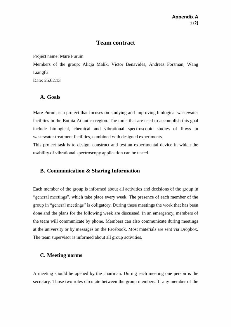
Team contract
Project name: Mare Purum
Members of the group: Alicja Malik, Victor Benavides, Andreas Forsman, Wang
Liangfu
Date: 25.02.13
A. Goals
Mare Purum is a project that focuses on studying and improving biological wastewater
facilities in the Botnia-Atlantica region. The tools that are used to accomplish this goal
include biological, chemical and vibrational spectroscopic studies of flows in
wastewater treatment facilities, combined with designed experiments.
This project task is to design, construct and test an experimental device in which the
usability of vibrational spectroscopy application can be tested.
B. Communication & Sharing Information
Each member of the group is informed about all activities and decisions of the group in
“general meetings”, which take place every week. The presence of each member of the
group in “general meetings” is obligatory. During these meetings the work that has been
done and the plans for the following week are discussed. In an emergency, members of
the team will communicate by phone. Members can also communicate during meetings
at the university or by messages on the Facebook. Most materials are sent via Dropbox.
The team supervisor is informed about all group activities.
C. Meeting norms
A meeting should be opened by the chairman. During each meeting one person is the
secretary. Those two roles circulate between the group members. If any member of the
Appendix A 2 (2)
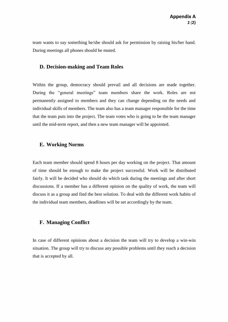
team wants to say something he/she should ask for permission by raising his/her hand.
During meetings all phones should be muted.
D. Decision-making and Team Roles
Within the group, democracy should prevail and all decisions are made together.
During the “general meetings” team members share the work. Roles are not
permanently assigned to members and they can change depending on the needs and
individual skills of members. The team also has a team manager responsible for the time
that the team puts into the project. The team votes who is going to be the team manager
until the mid-term report, and then a new team manager will be appointed.
E. Working Norms
Each team member should spend 8 hours per day working on the project. That amount
of time should be enough to make the project successful. Work will be distributed
fairly. It will be decided who should do which task during the meetings and after short
discussions. If a member has a different opinion on the quality of work, the team will
discuss it as a group and find the best solution. To deal with the different work habits of
the individual team members, deadlines will be set accordingly by the team.
F. Managing Conflict
In case of different opinions about a decision the team will try to develop a win-win
situation. The group will try to discuss any possible problems until they reach a decision
that is accepted by all.
Appendix B 1 (3)
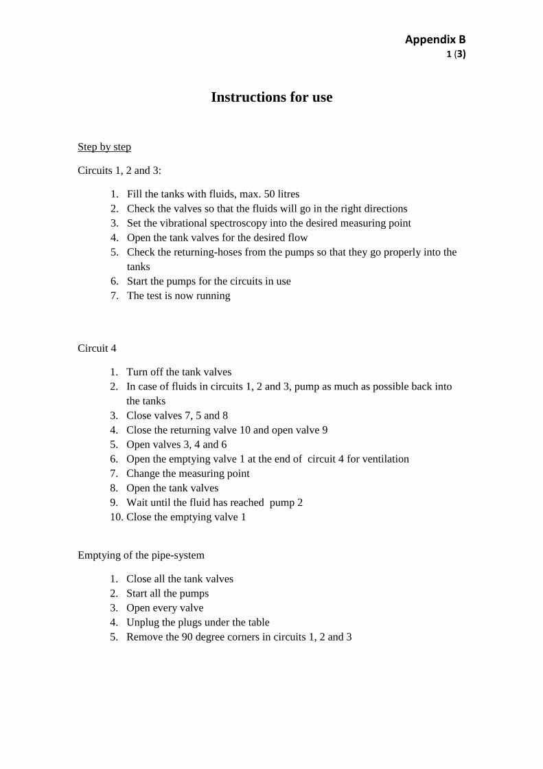
Instructions for use
Step by step
Circuits 1, 2 and 3:
1. Fill the tanks with fluids, max. 50 litres
2. Check the valves so that the fluids will go in the right directions
3. Set the vibrational spectroscopy into the desired measuring point
4. Open the tank valves for the desired flow
5. Check the returning-hoses from the pumps so that they go properly into the
tanks
6. Start the pumps for the circuits in use
7. The test is now running
Circuit 4
1. Turn off the tank valves
2. In case of fluids in circuits 1, 2 and 3, pump as much as possible back into
the tanks
3. Close valves 7, 5 and 8
4. Close the returning valve 10 and open valve 9
5. Open valves 3, 4 and 6
6. Open the emptying valve 1 at the end of circuit 4 for ventilation
7. Change the measuring point
8. Open the tank valves
9. Wait until the fluid has reached pump 2
10. Close the emptying valve 1
Emptying of the pipe-system
1. Close all the tank valves
2. Start all the pumps
3. Open every valve
4. Unplug the plugs under the table
5. Remove the 90 degree corners in circuits 1, 2 and 3
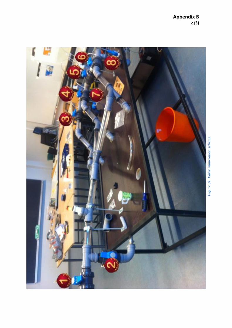
Appendix B 2 (3)
Fig
ure
31
. V
alv
e n
um
era
tio
n s
chem
e
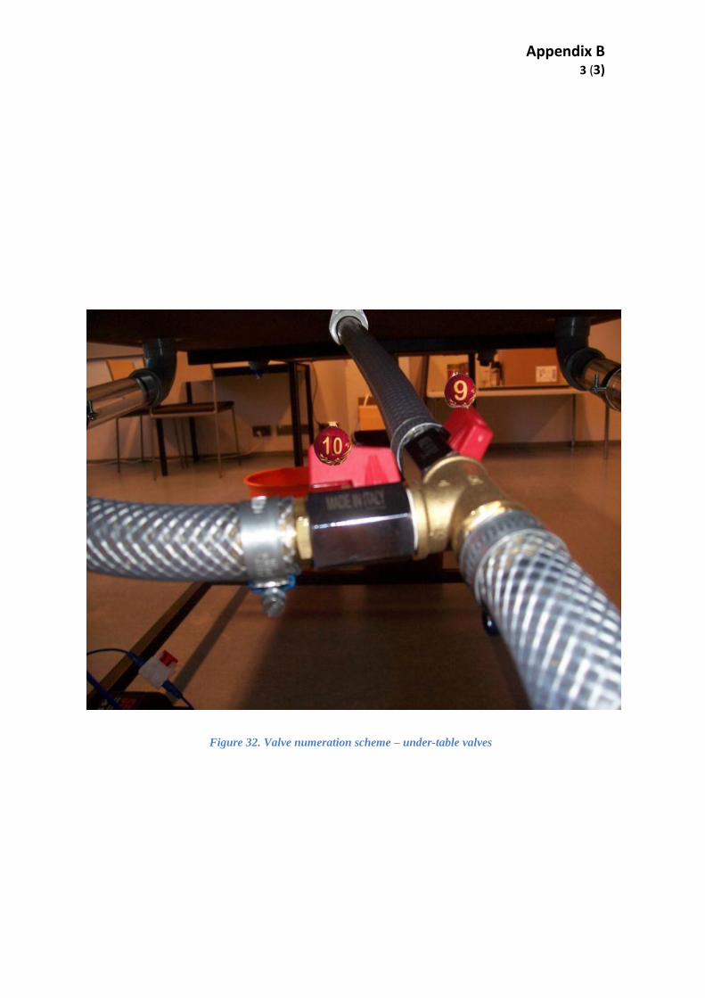
Appendix B 3 (3)
Figure 32. Valve numeration scheme – under-table valves