Embed Size (px)
Citation preview
HMC7000 Series Ladder Logic Guide i
Ladder Logic Guide For the HMC7000 Series
For use with the following:
HMC7000 Series
Maple Systems, Inc. | 808 134th St. SW, Suite 120, Everett, WA 98204 | 425.745.3229
Your Industrial Control Solutions Source _____________________
www.maplesystems.com

HMC7000 Series Ladder Logic Guide ii
HMC7000 Series Ladder Logic Guide ii
COPYRIGHT NOTICE This manual is a publication of Maple Systems, Inc., and is provided for use by its
customers only. The contents of the manual are copyrighted by Maple Systems, Inc.;
reproduction in whole or in part, for use other than in support of Maple Systems
equipment, is prohibited without the specific written permission of Maple Systems.
WARRANTY Warranty Statements are included with each unit at the time of purchase and are
available at www.maplesystems.com.
TECHNICAL SUPPORT This manual is designed to provide the necessary information for trouble-free
installation and operation of Maple Systems products. However, if you need assistance,
please contact Maple Systems:
Phone: 425-745-3229
Email: [email protected]
Web: www.maplesystems.com
HMC7000 Series Ladder Logic Guide iii
HMC7000 Series Ladder Logic Guide iii
Table of Contents COPYRIGHT NOTICE .................................................................................................... ii
WARRANTY................................................................................................................. ii
TECHNICAL SUPPORT .................................................................................................. ii
Table of Contents ....................................................................................................... iii
Chapter 1 – Native Ladder Logic Editor ........................................................................ 9
Introduction .......................................................................................................................9
Ladder Logic .......................................................................................................................9
Ladder Nets ...................................................................................................................... 10
Rungs ............................................................................................................................... 11
Placing elements in a ladder rung ......................................................................................... 12
Errors when placing elements in rungs ................................................................................. 13
Moving elements in rungs ..................................................................................................... 14
Cutting, copying, pasting elements in rungs ......................................................................... 15
Shortcuts when editing the ladder rungs .............................................................................. 16
Using Rung Comments .......................................................................................................... 17
Logic Block Types ............................................................................................................. 17
Main Program block .............................................................................................................. 18
Power-Up block ..................................................................................................................... 18
Subroutines .......................................................................................................................... 19
Timer Interrupts .................................................................................................................... 19
I/O Interrupts 1 and 2 ............................................................................................................ 20
Creating A Simple Ladder Logic Program ........................................................................... 20
Create a Logic Block ............................................................................................................... 20
Create Tags to Use in the Program ........................................................................................ 21
Configure Instructions in the Logic Block .............................................................................. 21
Create a Screen to View the Output ..................................................................................... 23
Compiler Output .................................................................................................................... 24
Downloading the Ladder Logic .......................................................................................... 25
Online Monitoring and Debugging .................................................................................... 25
Getting Connected................................................................................................................. 25
HMC7000 Series Ladder Logic Guide iv
HMC7000 Series Ladder Logic Guide iv
Monitor .................................................................................................................................. 26
Debug .................................................................................................................................... 28
Other Useful Ladder Logic Tools ........................................................................................ 32
Importing Ladder Logic Blocks from another project ............................................................ 32
Configuring color preferences ............................................................................................... 34
Chapter 2 - Ladder Instruction Table .......................................................................... 35
Input/Output Instructions ................................................................................................ 35
Data Transfer Instructions ................................................................................................ 36
Math Instructions ............................................................................................................. 37
Compare Instructions ....................................................................................................... 39
Logic Instructions ............................................................................................................. 40
Conversion Instructions .................................................................................................... 42
Timer Instructions ............................................................................................................ 43
Counter Instructions ......................................................................................................... 44
Program Control Instructions ............................................................................................ 44
Functions Instructions ...................................................................................................... 45
Special Instructions .......................................................................................................... 46
Chapter 3 - Instructions Defined ................................................................................ 48
Input/Output Instructions ................................................................................................ 48
NO Contact ............................................................................................................................ 48
NC Contact ............................................................................................................................. 49
Output ................................................................................................................................... 50
Rising Edge (Transitional Contact) ......................................................................................... 51
Falling Edge (Transitional Contact) ........................................................................................ 52
Inverter .................................................................................................................................. 53
Invert Coil .............................................................................................................................. 54
Positive Pulse Contact ........................................................................................................... 55
Negative Pulse Contact .......................................................................................................... 56
Positive Pulse Coil .................................................................................................................. 57
Negative Pulse Coil ................................................................................................................ 58
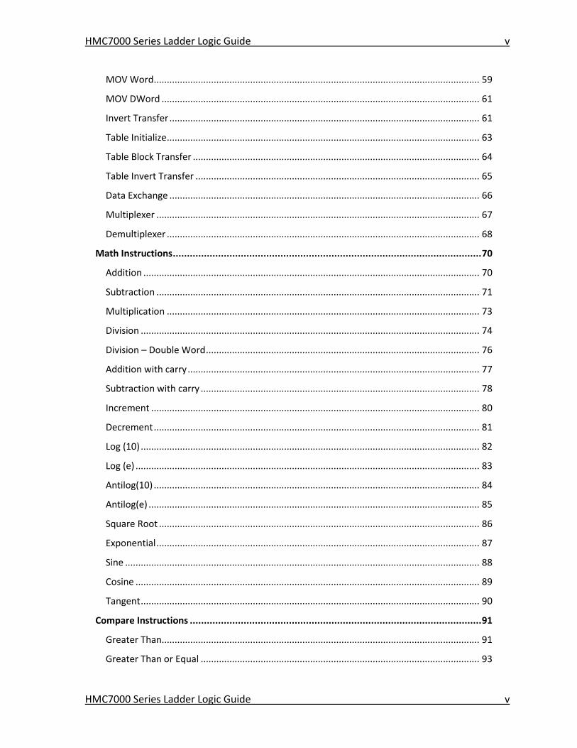
Data Transfer Instructions ................................................................................................ 59
HMC7000 Series Ladder Logic Guide v
HMC7000 Series Ladder Logic Guide v
MOV Word ............................................................................................................................. 59
MOV DWord .......................................................................................................................... 61
Invert Transfer ....................................................................................................................... 61
Table Initialize ........................................................................................................................ 63
Table Block Transfer .............................................................................................................. 64
Table Invert Transfer ............................................................................................................. 65
Data Exchange ....................................................................................................................... 66
Multiplexer ............................................................................................................................ 67
Demultiplexer ........................................................................................................................ 68
Math Instructions ............................................................................................................. 70
Addition ................................................................................................................................. 70
Subtraction ............................................................................................................................ 71
Multiplication ........................................................................................................................ 73
Division .................................................................................................................................. 74
Division – Double Word ......................................................................................................... 76
Addition with carry ................................................................................................................ 77
Subtraction with carry ........................................................................................................... 78
Increment .............................................................................................................................. 80
Decrement ............................................................................................................................. 81
Log (10) .................................................................................................................................. 82
Log (e) .................................................................................................................................... 83
Antilog(10) ............................................................................................................................. 84
Antilog(e) ............................................................................................................................... 85
Square Root ........................................................................................................................... 86
Exponential ............................................................................................................................ 87
Sine ........................................................................................................................................ 88
Cosine .................................................................................................................................... 89
Tangent .................................................................................................................................. 90
Compare Instructions ....................................................................................................... 91
Greater Than.......................................................................................................................... 91
Greater Than or Equal ........................................................................................................... 93
HMC7000 Series Ladder Logic Guide vi
HMC7000 Series Ladder Logic Guide vi
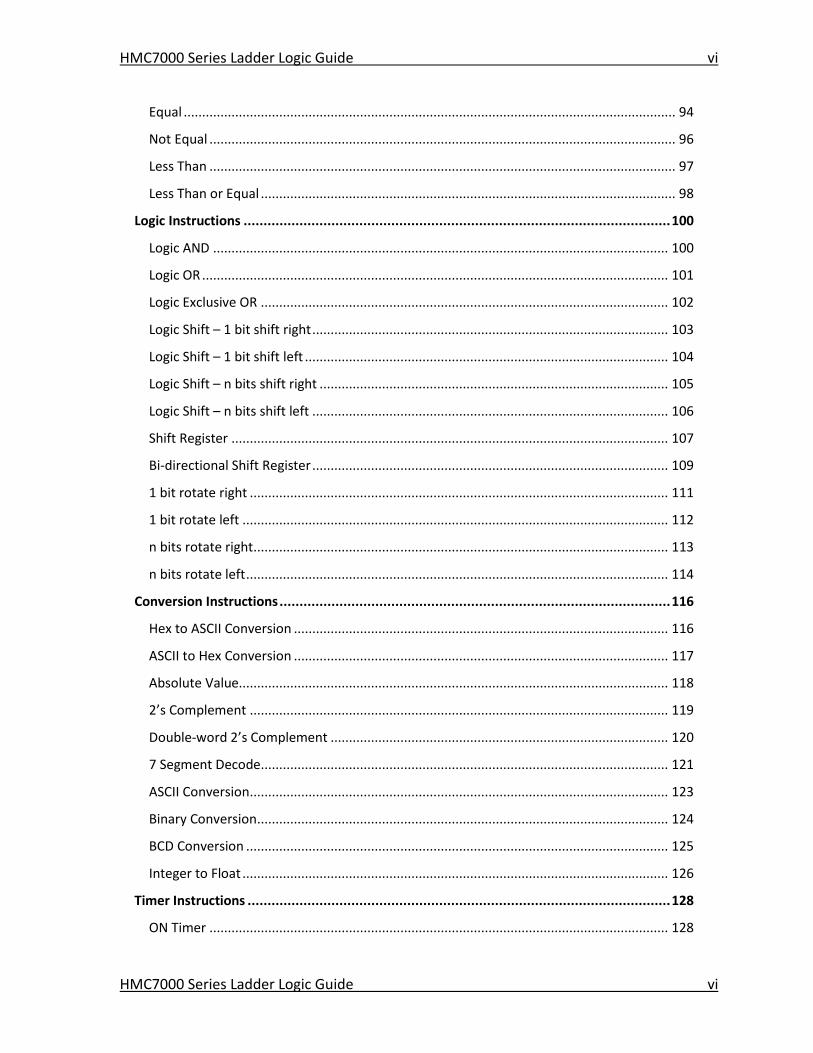
Equal ...................................................................................................................................... 94
Not Equal ............................................................................................................................... 96
Less Than ............................................................................................................................... 97
Less Than or Equal ................................................................................................................. 98
Logic Instructions ........................................................................................................... 100
Logic AND ............................................................................................................................ 100
Logic OR ............................................................................................................................... 101
Logic Exclusive OR ............................................................................................................... 102
Logic Shift – 1 bit shift right ................................................................................................. 103
Logic Shift – 1 bit shift left ................................................................................................... 104
Logic Shift – n bits shift right ............................................................................................... 105
Logic Shift – n bits shift left ................................................................................................. 106
Shift Register ....................................................................................................................... 107
Bi-directional Shift Register ................................................................................................. 109
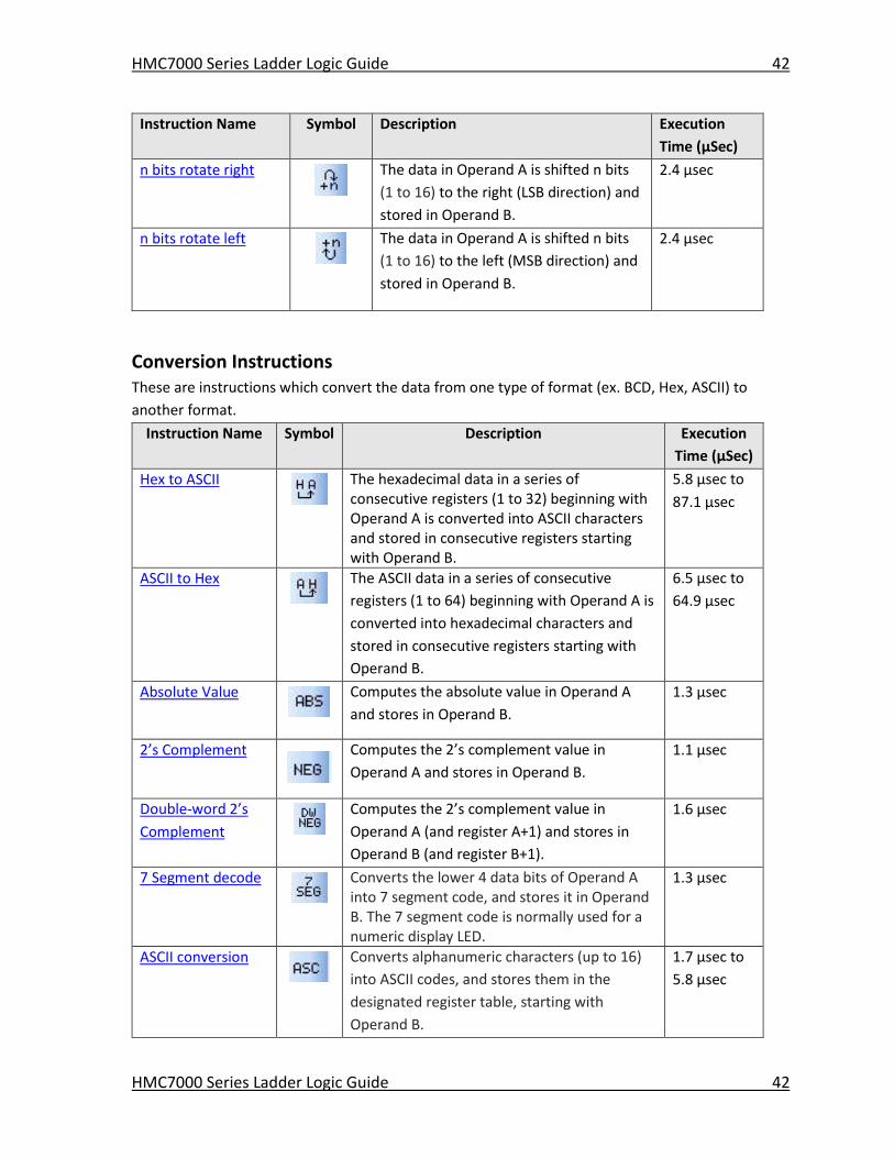
1 bit rotate right .................................................................................................................. 111
1 bit rotate left .................................................................................................................... 112
n bits rotate right ................................................................................................................. 113
n bits rotate left ................................................................................................................... 114
Conversion Instructions .................................................................................................. 116
Hex to ASCII Conversion ...................................................................................................... 116
ASCII to Hex Conversion ...................................................................................................... 117
Absolute Value..................................................................................................................... 118
2’s Complement .................................................................................................................. 119
Double-word 2’s Complement ............................................................................................ 120
7 Segment Decode ............................................................................................................... 121
ASCII Conversion .................................................................................................................. 123
Binary Conversion ................................................................................................................ 124
BCD Conversion ................................................................................................................... 125
Integer to Float .................................................................................................................... 126
Timer Instructions .......................................................................................................... 128
ON Timer ............................................................................................................................. 128
HMC7000 Series Ladder Logic Guide vii
HMC7000 Series Ladder Logic Guide vii
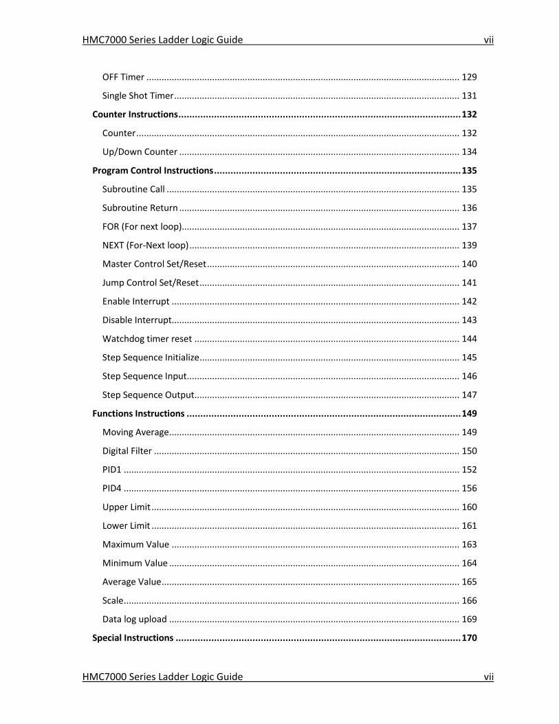
OFF Timer ............................................................................................................................ 129
Single Shot Timer ................................................................................................................. 131
Counter Instructions ....................................................................................................... 132
Counter ................................................................................................................................ 132
Up/Down Counter ............................................................................................................... 134
Program Control Instructions .......................................................................................... 135
Subroutine Call .................................................................................................................... 135
Subroutine Return ............................................................................................................... 136
FOR (For next loop).............................................................................................................. 137
NEXT (For-Next loop) ........................................................................................................... 139
Master Control Set/Reset .................................................................................................... 140
Jump Control Set/Reset ....................................................................................................... 141
Enable Interrupt .................................................................................................................. 142
Disable Interrupt.................................................................................................................. 143
Watchdog timer reset ......................................................................................................... 144
Step Sequence Initialize ....................................................................................................... 145
Step Sequence Input............................................................................................................ 146
Step Sequence Output ......................................................................................................... 147
Functions Instructions .................................................................................................... 149
Moving Average ................................................................................................................... 149
Digital Filter ......................................................................................................................... 150
PID1 ..................................................................................................................................... 152
PID4 ..................................................................................................................................... 156
Upper Limit .......................................................................................................................... 160
Lower Limit .......................................................................................................................... 161
Maximum Value .................................................................................................................. 163
Minimum Value ................................................................................................................... 164
Average Value ...................................................................................................................... 165
Scale ..................................................................................................................................... 166
Data log upload ................................................................................................................... 169
Special Instructions ........................................................................................................ 170
HMC7000 Series Ladder Logic Guide viii
HMC7000 Series Ladder Logic Guide viii
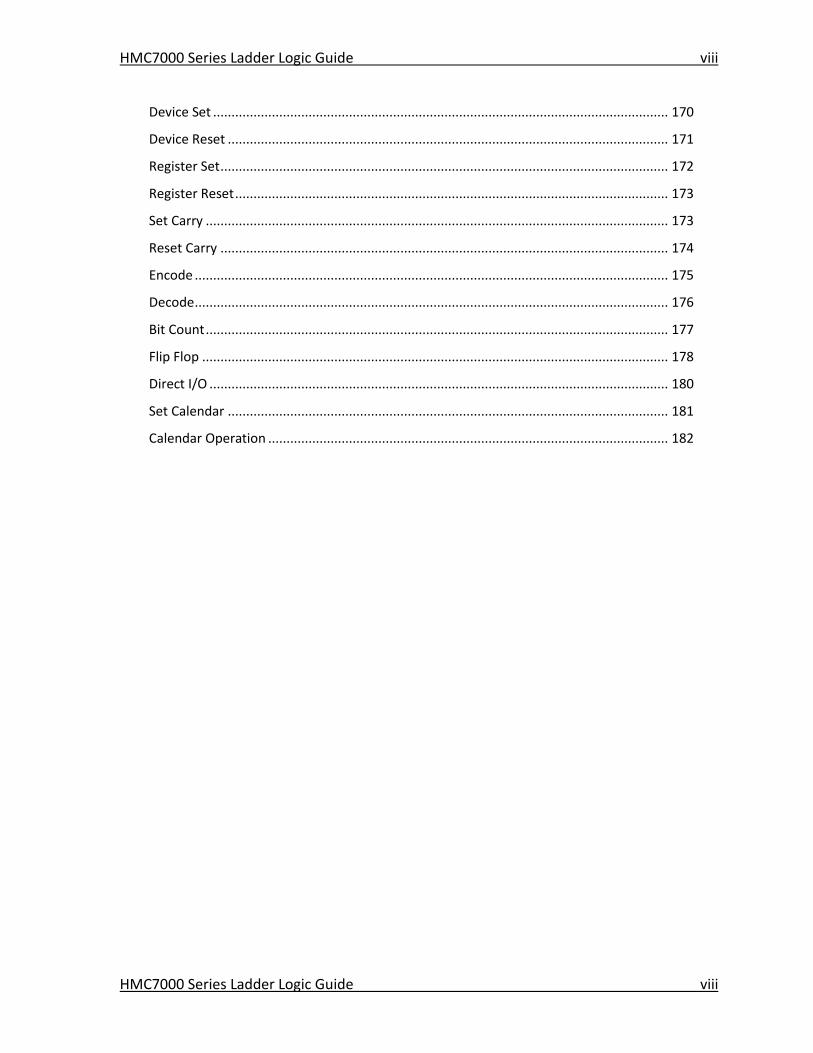
Device Set ............................................................................................................................ 170
Device Reset ........................................................................................................................ 171
Register Set .......................................................................................................................... 172
Register Reset ...................................................................................................................... 173
Set Carry .............................................................................................................................. 173
Reset Carry .......................................................................................................................... 174
Encode ................................................................................................................................. 175
Decode ................................................................................................................................. 176
Bit Count .............................................................................................................................. 177
Flip Flop ............................................................................................................................... 178
Direct I/O ............................................................................................................................. 180
Set Calendar ........................................................................................................................ 181
Calendar Operation ............................................................................................................. 182
HMC7000 Series Ladder Logic Guide 9
HMC7000 Series Ladder Logic Guide 9
Chapter 1 – Native Ladder Logic Editor
Introduction Logic blocks are a very useful and significant part of the feature set of the HMC7000 products. A
logic block is a series of ladder logic instructions or commands that is executed by the HMC7000.
As you will see later in this chapter, there are different types of logic blocks. These blocks vary
according to how they are initiated and in the order of execution. The following six types of logic
blocks are supported:
Main program
Power up
Timer Interrupt
I/O Interrupt #1 (HMC7030A-L only)
I/O Interrupt #2 (HMC7030A-L only)
Subroutine
By creating logic blocks of each of the above types and filling them with Ladder Logic
instructions, the programmer can configure the HMC to interact with input from the operator
and with the environment through the IO blocks connected to HMC. The possibilities are limited
only by the programmer’s imagination. This guide will help you become more familiar with the
tools available to quickly translate your ideas into a responsive, interactive and versatile system.
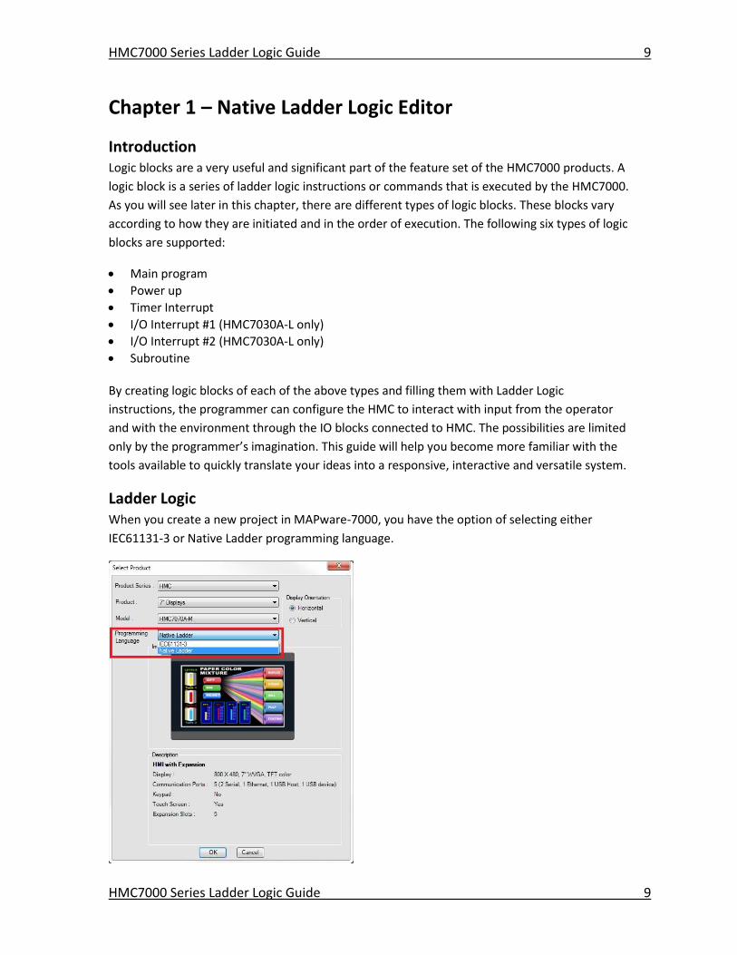
Ladder Logic When you create a new project in MAPware-7000, you have the option of selecting either
IEC61131-3 or Native Ladder programming language.
HMC7000 Series Ladder Logic Guide 10
HMC7000 Series Ladder Logic Guide 10
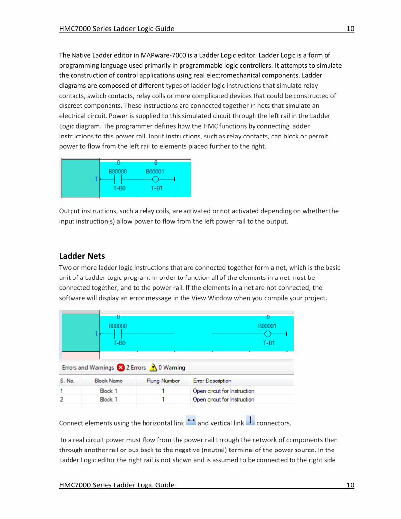
The Native Ladder editor in MAPware-7000 is a Ladder Logic editor. Ladder Logic is a form of
programming language used primarily in programmable logic controllers. It attempts to simulate
the construction of control applications using real electromechanical components. Ladder
diagrams are composed of different types of ladder logic instructions that simulate relay
contacts, switch contacts, relay coils or more complicated devices that could be constructed of
discreet components. These instructions are connected together in nets that simulate an
electrical circuit. Power is supplied to this simulated circuit through the left rail in the Ladder
Logic diagram. The programmer defines how the HMC functions by connecting ladder
instructions to this power rail. Input instructions, such as relay contacts, can block or permit
power to flow from the left rail to elements placed further to the right.
Output instructions, such a relay coils, are activated or not activated depending on whether the
input instruction(s) allow power to flow from the left power rail to the output.
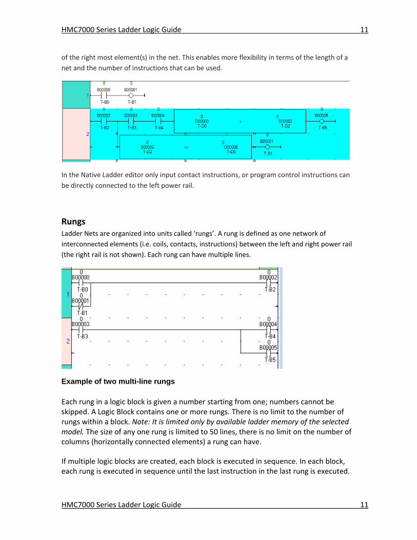
Ladder Nets Two or more ladder logic instructions that are connected together form a net, which is the basic
unit of a Ladder Logic program. In order to function all of the elements in a net must be
connected together, and to the power rail. If the elements in a net are not connected, the
software will display an error message in the View Window when you compile your project.
Connect elements using the horizontal link and vertical link connectors.
In a real circuit power must flow from the power rail through the network of components then
through another rail or bus back to the negative (neutral) terminal of the power source. In the
Ladder Logic editor the right rail is not shown and is assumed to be connected to the right side
HMC7000 Series Ladder Logic Guide 11
HMC7000 Series Ladder Logic Guide 11
of the right most element(s) in the net. This enables more flexibility in terms of the length of a
net and the number of instructions that can be used.
In the Native Ladder editor only input contact instructions, or program control instructions can
be directly connected to the left power rail.
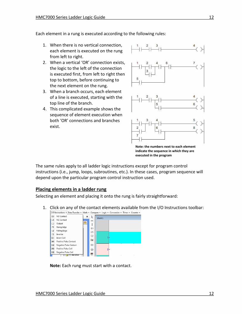
Rungs Ladder Nets are organized into units called ‘rungs’. A rung is defined as one network of
interconnected elements (i.e. coils, contacts, instructions) between the left and right power rail
(the right rail is not shown). Each rung can have multiple lines.
Example of two multi-line rungs
Each rung in a logic block is given a number starting from one; numbers cannot be skipped. A Logic Block contains one or more rungs. There is no limit to the number of rungs within a block. Note: It is limited only by available ladder memory of the selected model. The size of any one rung is limited to 50 lines, there is no limit on the number of columns (horizontally connected elements) a rung can have.
If multiple logic blocks are created, each block is executed in sequence. In each block, each rung is executed in sequence until the last instruction in the last rung is executed.
HMC7000 Series Ladder Logic Guide 12
HMC7000 Series Ladder Logic Guide 12
Each element in a rung is executed according to the following rules:
1. When there is no vertical connection, each element is executed on the rung from left to right.
2. When a vertical ‘OR’ connection exists, the logic to the left of the connection is executed first, from left to right then top to bottom, before continuing to the next element on the rung.
3. When a branch occurs, each element of a line is executed, starting with the top line of the branch.
4. This complicated example shows the sequence of element execution when both ‘OR’ connections and branches exist.
Note: the numbers next to each element indicate the sequence in which they are executed in the program
The same rules apply to all ladder logic instructions except for program control instructions (i.e., jump, loops, subroutines, etc.). In these cases, program sequence will depend upon the particular program control instruction used.
Placing elements in a ladder rung
Selecting an element and placing it onto the rung is fairly straightforward:
1. Click on any of the contact elements available from the I/O Instructions toolbar:
Note: Each rung must start with a contact.
HMC7000 Series Ladder Logic Guide 13
HMC7000 Series Ladder Logic Guide 13
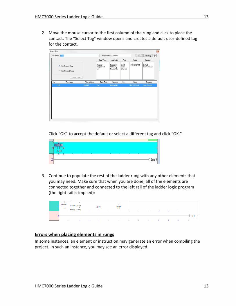
2. Move the mouse cursor to the first column of the rung and click to place the contact. The “Select Tag” window opens and creates a default user-defined tag for the contact.
Click “OK” to accept the default or select a different tag and click “OK.”
3. Continue to populate the rest of the ladder rung with any other elements that you may need. Make sure that when you are done, all of the elements are connected together and connected to the left rail of the ladder logic program (the right rail is implied):
Errors when placing elements in rungs
In some instances, an element or instruction may generate an error when compiling the project. In such an instance, you may see an error displayed.
HMC7000 Series Ladder Logic Guide 14
HMC7000 Series Ladder Logic Guide 14
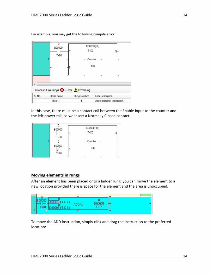
For example, you may get the following compile error:
In this case, there must be a contact coil between the Enable input to the counter and the left power rail, so we insert a Normally Closed contact:
Moving elements in rungs
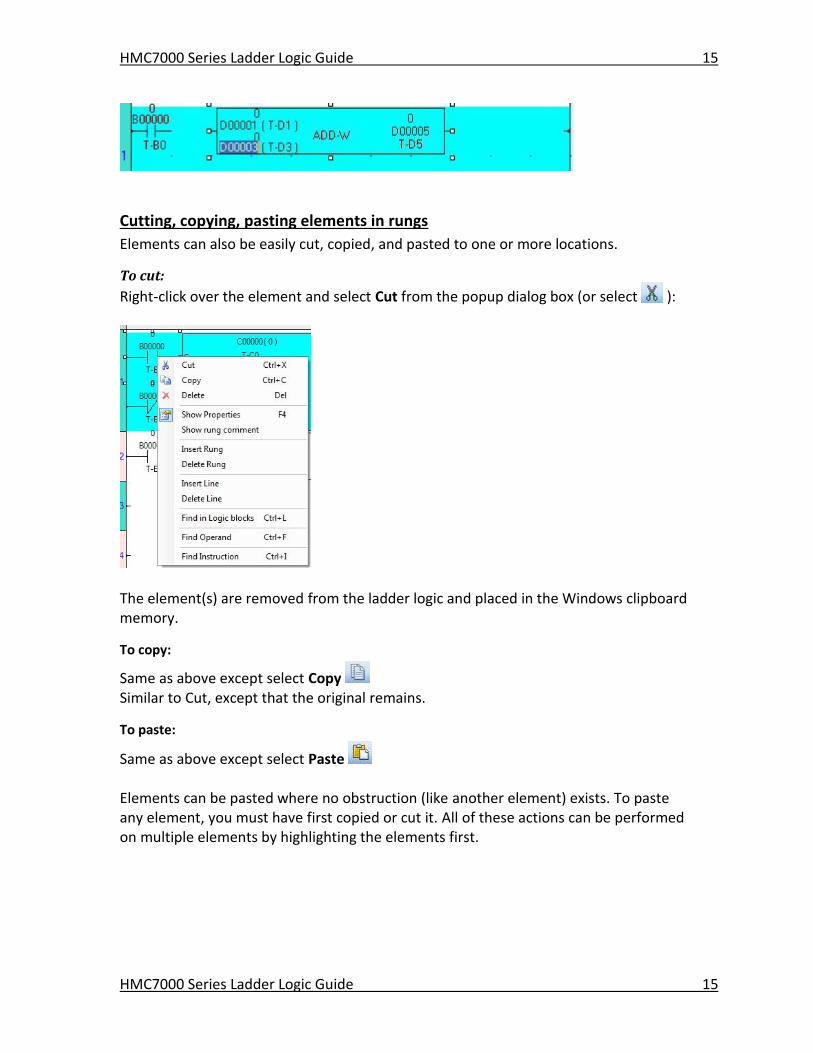
After an element has been placed onto a ladder rung, you can move the element to a new location provided there is space for the element and the area is unoccupied.
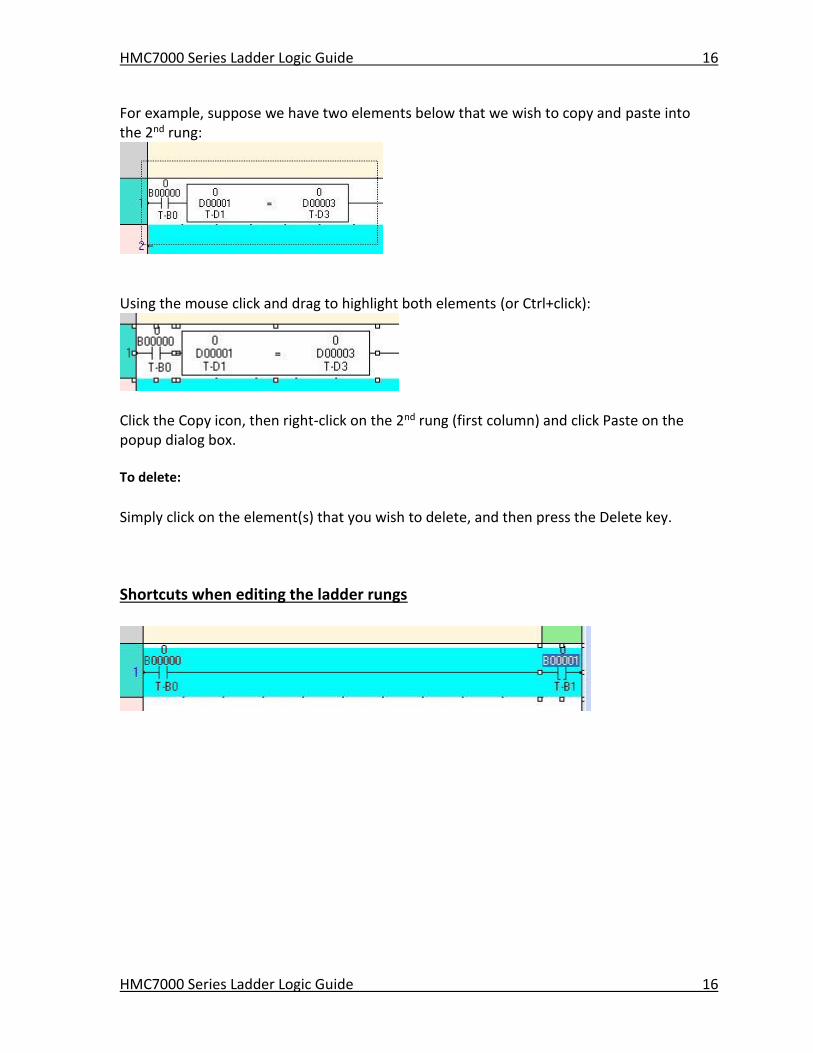
To move the ADD instruction, simply click and drag the instruction to the preferred location:
HMC7000 Series Ladder Logic Guide 15
HMC7000 Series Ladder Logic Guide 15
Cutting, copying, pasting elements in rungs
Elements can also be easily cut, copied, and pasted to one or more locations.
To cut:
Right-click over the element and select Cut from the popup dialog box (or select ):
The element(s) are removed from the ladder logic and placed in the Windows clipboard memory.
To copy:
Same as above except select Copy Similar to Cut, except that the original remains.
To paste:
Same as above except select Paste Elements can be pasted where no obstruction (like another element) exists. To paste any element, you must have first copied or cut it. All of these actions can be performed on multiple elements by highlighting the elements first.
HMC7000 Series Ladder Logic Guide 16
HMC7000 Series Ladder Logic Guide 16
For example, suppose we have two elements below that we wish to copy and paste into the 2nd rung:
Using the mouse click and drag to highlight both elements (or Ctrl+click):
Click the Copy icon, then right-click on the 2nd rung (first column) and click Paste on the popup dialog box.
To delete:
Simply click on the element(s) that you wish to delete, and then press the Delete key.
Shortcuts when editing the ladder rungs
HMC7000 Series Ladder Logic Guide 17
HMC7000 Series Ladder Logic Guide 17
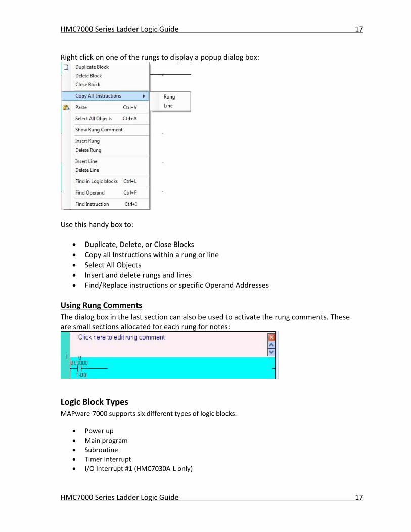
Right click on one of the rungs to display a popup dialog box:
Use this handy box to:
Duplicate, Delete, or Close Blocks
Copy all Instructions within a rung or line
Select All Objects
Insert and delete rungs and lines
Find/Replace instructions or specific Operand Addresses
Using Rung Comments
The dialog box in the last section can also be used to activate the rung comments. These are small sections allocated for each rung for notes:
Logic Block Types MAPware-7000 supports six different types of logic blocks:
Power up
Main program
Subroutine
Timer Interrupt
I/O Interrupt #1 (HMC7030A-L only)
HMC7000 Series Ladder Logic Guide 18
HMC7000 Series Ladder Logic Guide 18
I/O Interrupt #2 (HMC7030A-L only)
Although each logic block is basically the same, each type is targeted for special purposes.
Main Program block
The main program is the core of the user program. It is executed once during each scan.
Multiple logic blocks can be created (up to 256) and used in the Main Program block. During
execution, the HMC7000 starts with the first block listed. When completed, it will execute each
block in sequence. Each logic block can contain an END instruction to indicate where execution
of instructions ends and the program is exited. Please note that you can place additional
instructions after the END instruction, though these will not be executed during operation. The
figure below shows a typical scan sequence:
1 scan time
Mode I/O Timers Main
Program
Mode I/O Timers Main
Program
Time
Where:
Mode- determines mode of operation (Run, Halt, etc.)
I/O- update and process all inputs and outputs
Timer- update all running timers
Main Program- all logic blocks created under Main
Power-Up block
If the Power up-program is programmed, it is executed once at the beginning of the first scan
(before main program execution). Therefore, this program can be used to set initial values into
registers.
The figure below shows the first scan operation:
Run mode
Transition 1st scan 2nd scan…
I/O Timers Power-
up
Main
Program
Mode I/O Timers Main
Program
Time
HMC7000 Series Ladder Logic Guide 19
HMC7000 Series Ladder Logic Guide 19
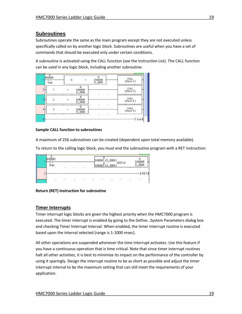
Subroutines Subroutines operate the same as the main program except they are not executed unless
specifically called on by another logic block. Subroutines are useful when you have a set of
commands that should be executed only under certain conditions.
A subroutine is activated using the CALL function (see the Instruction List). The CALL function
can be used in any logic block, including another subroutine:
Sample CALL function to subroutines
A maximum of 256 subroutines can be created (dependent upon total memory available).
To return to the calling logic block, you must end the subroutine program with a RET instruction:
Return (RET) instruction for subroutine
Timer Interrupts
Timer interrupt logic blocks are given the highest priority when the HMC7000 program is
executed. The timer interrupt is enabled by going to the Define…System Parameters dialog box
and checking Timer Interrupt Interval. When enabled, the timer interrupt routine is executed
based upon the interval selected (range is 1-1000 msec).
All other operations are suspended whenever the time interrupt activates. Use this feature if
you have a continuous operation that is time critical. Note that since timer interrupt routines
halt all other activities, it is best to minimize its impact on the performance of the controller by
using it sparingly. Design the interrupt routine to be as short as possible and adjust the timer
interrupt interval to be the maximum setting that can still meet the requirements of your
application.
HMC7000 Series Ladder Logic Guide 20
HMC7000 Series Ladder Logic Guide 20
I/O Interrupts 1 and 2 The I/O interrupt program is also a high priority task. It is executed immediately when the
interrupt factor is generated, while suspending other operations.
Two I/O interrupt programs are supported in the HMC7000 unit. Note: only models with built-in
IO modules such as the HMC7030A-L support the I/O interrupt blocks. The end of each Interrupt
program is recognized by the END instruction.
(1) I/O Interrupt #1 The I/O Interrupt #1 is used with the high-speed counter function. When the count value reaches the preset value, etc., the I/O Interrupt #1 is activated immediately, suspending other operations.
(2) I/O Interrupt #2 The I/O Interrupt #2 is also used with the high-speed counter function. If an interrupt factor is generated while another interrupt program is executing (including the timer interrupt), the interrupt factor is held. Then it is activated after the first interrupt is finished executing.
Therefore, if two or more interrupt factors are generated at the same time, the priority is as follows:
1. Timer 2. I/O # 1 3. I/O # 2
Creating A Simple Ladder Logic Program The following is an example of how to create a simple ladder logic program. In this example, we
will use the HMC7035A-M and create a logic block in the Main section. This simple program will
activate a 10ms timer with the press of a button on Screen 1. The timer will count for ten
seconds, after which it will cause an output coil to turn ON. The output coil will be monitored on
Screen 1 using a bit lamp object.
Create a Logic Block Before Ladder Logic instructions can be placed in a logic block the block itself must be created. Perform the following steps:
1. In the Project’s Information window:
a. Click the Logic Blocks sub-folder for the currently opened project. (Note: if
necessary, click on the expansion symbol located to the left of the Logic Blocks subfolder to expand the directory.
b. Right-click on the appropriate Logic Blocks type (ex. Main) subfolder. c. A popup dialog box appears “New Logic Block”. Click on the dialog box.
HMC7000 Series Ladder Logic Guide 21
HMC7000 Series Ladder Logic Guide 21
2. A new logic block of the selected type is created and displayed in the work area and the Block Properties box displays to the right.
Create Tags to Use in the Program
Before creating the ladder logic, we must add the memory areas we intend to use to the tag
database. Create the following tags using the tag database (for information on how to use the
tag database, refer to Chapter 4 – Screens and Tags in the MAPware-7000 Programing Manual):
Node Name Tag Name Register/Coil Type Address Register or Coil
Operator Panel Start Timer Internal Coils (B) 0 Coil
Operator Panel Timer Set Internal Coils (B) 1 Coil
Operator Panel TR_00001 Timer Register (T) 1 Register
Operator Panel T_00001 Timer Coils (T.) 1 Coil
Configure Instructions in the Logic Block
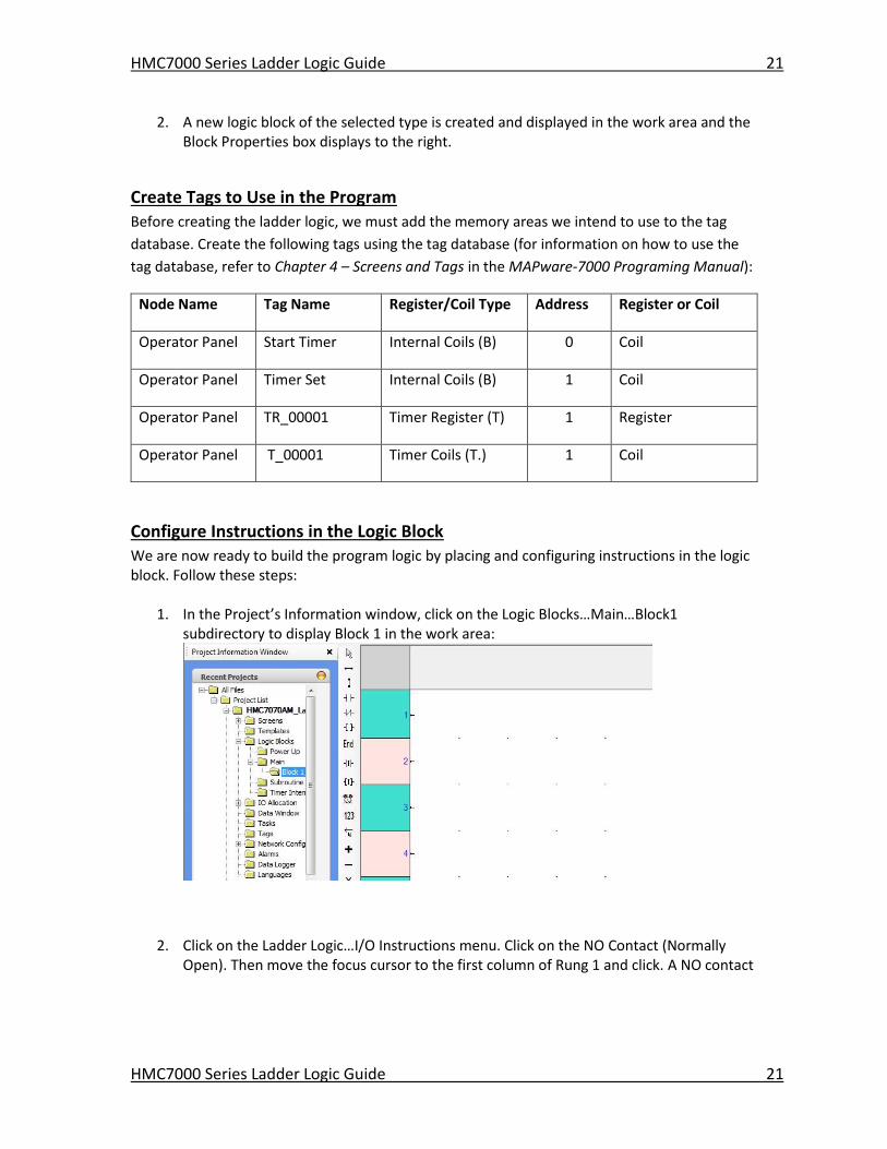
We are now ready to build the program logic by placing and configuring instructions in the logic block. Follow these steps:
1. In the Project’s Information window, click on the Logic Blocks…Main…Block1 subdirectory to display Block 1 in the work area:
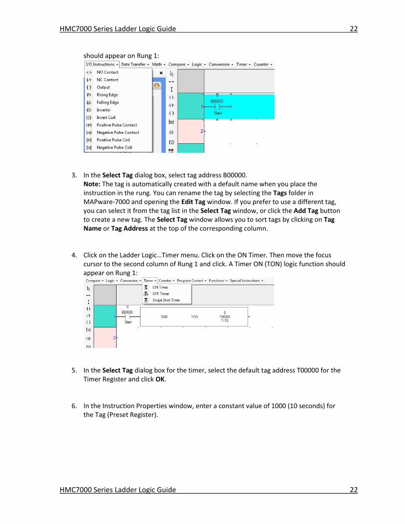
2. Click on the Ladder Logic…I/O Instructions menu. Click on the NO Contact (Normally Open). Then move the focus cursor to the first column of Rung 1 and click. A NO contact
HMC7000 Series Ladder Logic Guide 22
HMC7000 Series Ladder Logic Guide 22
should appear on Rung 1:
3. In the Select Tag dialog box, select tag address B00000. Note: The tag is automatically created with a default name when you place the instruction in the rung. You can rename the tag by selecting the Tags folder in MAPware-7000 and opening the Edit Tag window. If you prefer to use a different tag, you can select it from the tag list in the Select Tag window, or click the Add Tag button to create a new tag. The Select Tag window allows you to sort tags by clicking on Tag Name or Tag Address at the top of the corresponding column.
4. Click on the Ladder Logic…Timer menu. Click on the ON Timer. Then move the focus cursor to the second column of Rung 1 and click. A Timer ON (TON) logic function should appear on Rung 1:
5. In the Select Tag dialog box for the timer, select the default tag address T00000 for the
Timer Register and click OK.
6. In the Instruction Properties window, enter a constant value of 1000 (10 seconds) for the Tag (Preset Register).
HMC7000 Series Ladder Logic Guide 23
HMC7000 Series Ladder Logic Guide 23
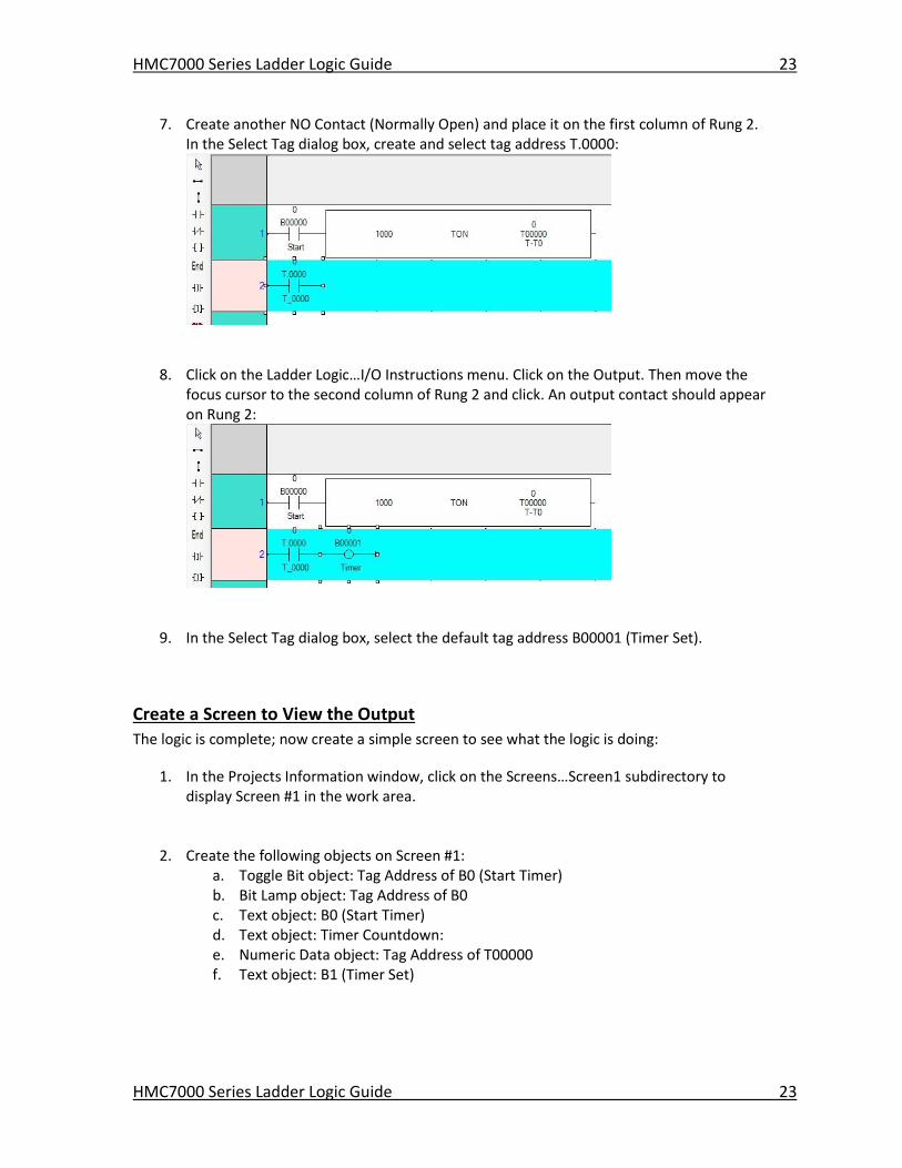
7. Create another NO Contact (Normally Open) and place it on the first column of Rung 2. In the Select Tag dialog box, create and select tag address T.0000:
8. Click on the Ladder Logic…I/O Instructions menu. Click on the Output. Then move the focus cursor to the second column of Rung 2 and click. An output contact should appear on Rung 2:
9. In the Select Tag dialog box, select the default tag address B00001 (Timer Set).
Create a Screen to View the Output
The logic is complete; now create a simple screen to see what the logic is doing:
1. In the Projects Information window, click on the Screens…Screen1 subdirectory to display Screen #1 in the work area.
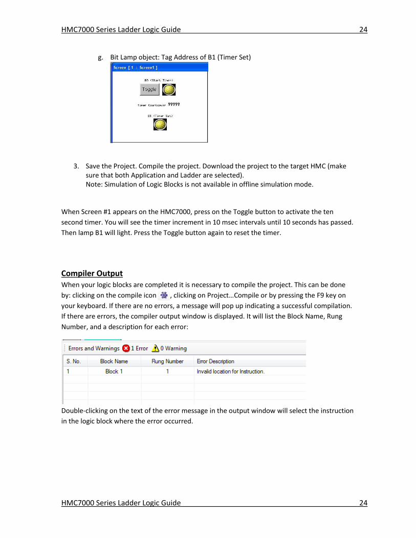
2. Create the following objects on Screen #1: a. Toggle Bit object: Tag Address of B0 (Start Timer) b. Bit Lamp object: Tag Address of B0 c. Text object: B0 (Start Timer) d. Text object: Timer Countdown: e. Numeric Data object: Tag Address of T00000 f. Text object: B1 (Timer Set)
HMC7000 Series Ladder Logic Guide 24
HMC7000 Series Ladder Logic Guide 24
g. Bit Lamp object: Tag Address of B1 (Timer Set)
3. Save the Project. Compile the project. Download the project to the target HMC (make sure that both Application and Ladder are selected). Note: Simulation of Logic Blocks is not available in offline simulation mode.
When Screen #1 appears on the HMC7000, press on the Toggle button to activate the ten
second timer. You will see the timer increment in 10 msec intervals until 10 seconds has passed.
Then lamp B1 will light. Press the Toggle button again to reset the timer.
Compiler Output
When your logic blocks are completed it is necessary to compile the project. This can be done
by: clicking on the compile icon , clicking on Project…Compile or by pressing the F9 key on
your keyboard. If there are no errors, a message will pop up indicating a successful compilation.
If there are errors, the compiler output window is displayed. It will list the Block Name, Rung
Number, and a description for each error:
Double-clicking on the text of the error message in the output window will select the instruction
in the logic block where the error occurred.

HMC7000 Series Ladder Logic Guide 25
HMC7000 Series Ladder Logic Guide 25
Downloading the Ladder Logic After saving and compiling (make sure no errors occur), you can download the project into your
HMC7000:
Click Project…Transfer…Download to display the Download menu:
Make sure that Firmware, Application, and Ladder are checked. Click the Download button to begin the download to the HMC7000 unit.
Online Monitoring and Debugging Ladder logic programs composed of many logic blocks each with many rungs can become very
complex. Programs rarely work exactly as the programmer intended the first time they are run.
Understanding exactly what the HMC is doing is nearly impossible without some visualization
tools. Fortunately, MAPware-7000 can be connected to an HMC while it is running a ladder logic
program, allowing the programmer to see and control the state of inputs, outputs and other
data the logic is operating on. In addition, a debugger allows the programmer to control
program execution and step through the logic blocks one instruction at a time, quickly
identifying and fixing any logical errors.
Getting Connected The first step to monitor logic in an HMC is to connect it to the PC running MAPware-7000. Click
on the Tools menu…Preferences…Online Communication Mode to select the connection
method used to go online.
Once connected, there are two options to go online with the HMC:
HMC7000 Series Ladder Logic Guide 26
HMC7000 Series Ladder Logic Guide 26
1. With Upload: This mode can be entered whether a project is currently open or not. If a
project is open, it will be closed; there will be an opportunity to save any changes. The
project on the HMC will be uploaded and opened in MAPware-7000, and the software
will be placed in online mode. To go online with upload:
a. Click on the Mode menu… Online… With Upload
b. Press the F8 key on the keyboard
c. Click on the online mode icon:
2. Without Upload: The project on the HMC must be open in MAPware-7000. If the ladder
logic has been modified since the last download, you will be prompted to download it
again. To go online without upload:
a. Click on the Mode menu… Online… Without Upload
b. Press the F6 key on the keyboard
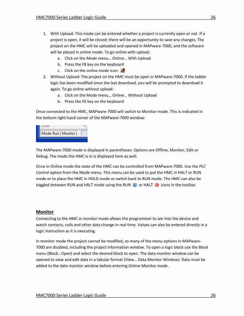
Once connected to the HMC, MAPware-7000 will switch to Monitor mode. This is indicated in
the bottom right hand corner of the MAPware-7000 window:
The MAPware-7000 mode is displayed in parentheses. Options are Offline, Monitor, Edit or
Debug. The mode the HMC is in is displayed here as well.
Once in Online mode the state of the HMC can be controlled from MAPware-7000. Use the PLC
Control option from the Mode menu. This menu can be used to put the HMC in HALT or RUN
mode or to place the HMC in HOLD mode or switch back to RUN mode. The HMC can also be
toggled between RUN and HALT mode using the RUN or HALT icons in the toolbar.
Monitor Connecting to the HMC in monitor mode allows the programmer to see into the device and
watch contacts, coils and other data change in real time. Values can also be entered directly in a
logic instruction as it is executing.
In monitor mode the project cannot be modified, so many of the menu options in MAPware-
7000 are disabled, including the project information window. To open a logic block use the Block
menu (Block…Open) and select the desired block to open. The data monitor window can be
opened to view and edit data in a tabular format (View… Data Monitor Window). Data must be
added to the data monitor window before entering Online-Monitor mode.
HMC7000 Series Ladder Logic Guide 27
HMC7000 Series Ladder Logic Guide 27
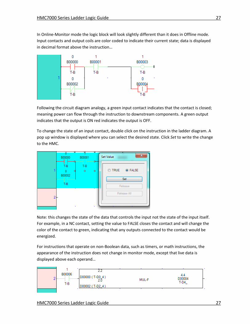
In Online-Monitor mode the logic block will look slightly different than it does in Offline mode.
Input contacts and output coils are color coded to indicate their current state; data is displayed
in decimal format above the instruction…
Following the circuit diagram analogy, a green input contact indicates that the contact is closed;
meaning power can flow through the instruction to downstream components. A green output
indicates that the output is ON red indicates the output is OFF.
To change the state of an input contact, double click on the instruction in the ladder diagram. A
pop up window is displayed where you can select the desired state. Click Set to write the change
to the HMC.
Note: this changes the state of the data that controls the input not the state of the input itself.
For example, in a NC contact, setting the value to FALSE closes the contact and will change the
color of the contact to green, indicating that any outputs connected to the contact would be
energized.
For instructions that operate on non-Boolean data, such as timers, or math instructions, the
appearance of the instruction does not change in monitor mode, except that live data is
displayed above each operand…
HMC7000 Series Ladder Logic Guide 28
HMC7000 Series Ladder Logic Guide 28
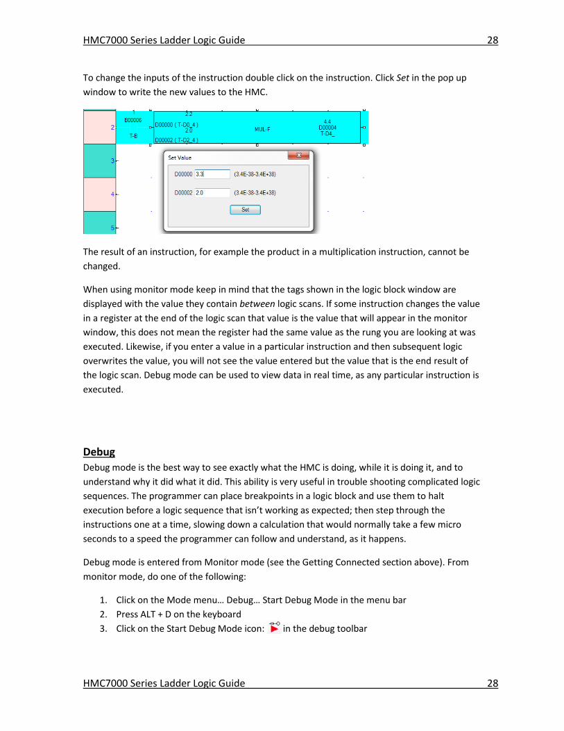
To change the inputs of the instruction double click on the instruction. Click Set in the pop up
window to write the new values to the HMC.
The result of an instruction, for example the product in a multiplication instruction, cannot be
changed.
When using monitor mode keep in mind that the tags shown in the logic block window are
displayed with the value they contain between logic scans. If some instruction changes the value
in a register at the end of the logic scan that value is the value that will appear in the monitor
window, this does not mean the register had the same value as the rung you are looking at was
executed. Likewise, if you enter a value in a particular instruction and then subsequent logic
overwrites the value, you will not see the value entered but the value that is the end result of
the logic scan. Debug mode can be used to view data in real time, as any particular instruction is
executed.
Debug
Debug mode is the best way to see exactly what the HMC is doing, while it is doing it, and to
understand why it did what it did. This ability is very useful in trouble shooting complicated logic
sequences. The programmer can place breakpoints in a logic block and use them to halt
execution before a logic sequence that isn’t working as expected; then step through the
instructions one at a time, slowing down a calculation that would normally take a few micro
seconds to a speed the programmer can follow and understand, as it happens.
Debug mode is entered from Monitor mode (see the Getting Connected section above). From
monitor mode, do one of the following:
1. Click on the Mode menu… Debug… Start Debug Mode in the menu bar
2. Press ALT + D on the keyboard
3. Click on the Start Debug Mode icon: in the debug toolbar
HMC7000 Series Ladder Logic Guide 29
HMC7000 Series Ladder Logic Guide 29
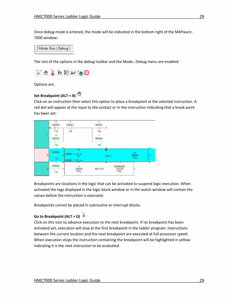
Once debug mode is entered, the mode will be indicated in the bottom right of the MAPware-
7000 window:
The rest of the options in the debug toolbar and the Mode…Debug menu are enabled:
Options are:
Set Breakpoint (ALT + B)
Click on an instruction then select this option to place a breakpoint at the selected instruction. A
red dot will appear at the input to the contact or in the instruction indicating that a break point
has been set:
Breakpoints are locations in the logic that can be activated to suspend logic execution. When
activated the tags displayed in the logic block window or in the watch window will contain the
values before the instruction is executed.
Breakpoints cannot be placed in subroutine or interrupt blocks.
Go to Breakpoint (ALT + G)
Click on this icon to advance execution to the next breakpoint. If no breakpoint has been
activated yet, execution will stop at the first breakpoint in the ladder program. Instructions
between the current location and the next breakpoint are executed at full processor speed.
When execution stops the instruction containing the breakpoint will be highlighted in yellow
indicating it is the next instruction to be evaluated.
HMC7000 Series Ladder Logic Guide 30
HMC7000 Series Ladder Logic Guide 30
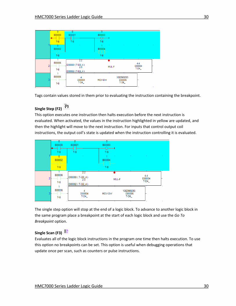
Tags contain values stored in them prior to evaluating the instruction containing the breakpoint.
Single Step (F2)
This option executes one instruction then halts execution before the next instruction is
evaluated. When activated, the values in the instruction highlighted in yellow are updated, and
then the highlight will move to the next instruction. For inputs that control output coil
instructions, the output coil’s state is updated when the instruction controlling it is evaluated.
The single step option will stop at the end of a logic block. To advance to another logic block in
the same program place a breakpoint at the start of each logic block and use the Go To
Breakpoint option.
Single Scan (F3)
Evaluates all of the logic block instructions in the program one time then halts execution. To use
this option no breakpoints can be set. This option is useful when debugging operations that
update once per scan, such as counters or pulse instructions.
HMC7000 Series Ladder Logic Guide 31
HMC7000 Series Ladder Logic Guide 31
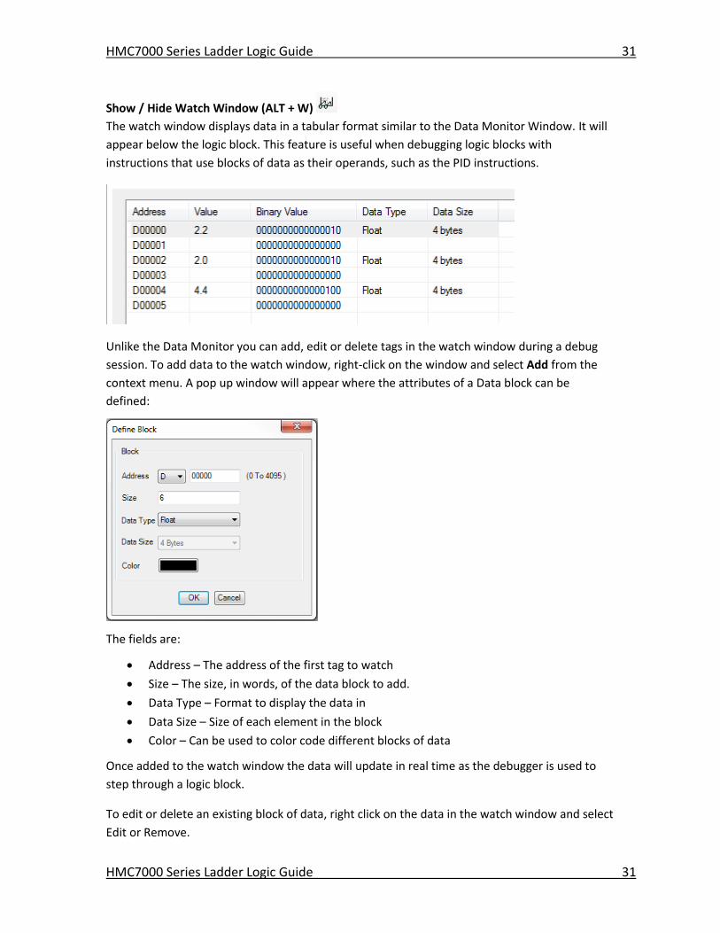
Show / Hide Watch Window (ALT + W)
The watch window displays data in a tabular format similar to the Data Monitor Window. It will
appear below the logic block. This feature is useful when debugging logic blocks with
instructions that use blocks of data as their operands, such as the PID instructions.
Unlike the Data Monitor you can add, edit or delete tags in the watch window during a debug
session. To add data to the watch window, right-click on the window and select Add from the
context menu. A pop up window will appear where the attributes of a Data block can be
defined:
The fields are:
Address – The address of the first tag to watch
Size – The size, in words, of the data block to add.
Data Type – Format to display the data in
Data Size – Size of each element in the block
Color – Can be used to color code different blocks of data
Once added to the watch window the data will update in real time as the debugger is used to
step through a logic block.
To edit or delete an existing block of data, right click on the data in the watch window and select
Edit or Remove.
HMC7000 Series Ladder Logic Guide 32
HMC7000 Series Ladder Logic Guide 32
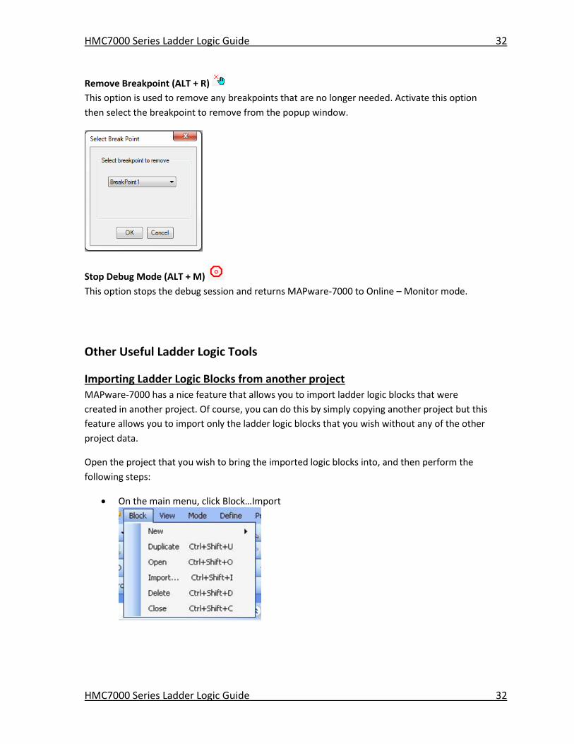
Remove Breakpoint (ALT + R)
This option is used to remove any breakpoints that are no longer needed. Activate this option
then select the breakpoint to remove from the popup window.
Stop Debug Mode (ALT + M)
This option stops the debug session and returns MAPware-7000 to Online – Monitor mode.
Other Useful Ladder Logic Tools
Importing Ladder Logic Blocks from another project MAPware-7000 has a nice feature that allows you to import ladder logic blocks that were
created in another project. Of course, you can do this by simply copying another project but this
feature allows you to import only the ladder logic blocks that you wish without any of the other
project data.
Open the project that you wish to bring the imported logic blocks into, and then perform the
following steps:
On the main menu, click Block…Import
HMC7000 Series Ladder Logic Guide 33
HMC7000 Series Ladder Logic Guide 33
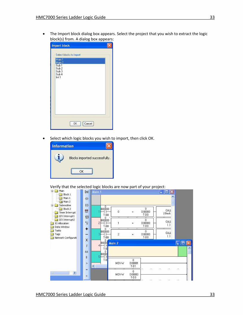
The Import block dialog box appears. Select the project that you wish to extract the logic block(s) from. A dialog box appears:
Select which logic blocks you wish to import, then click OK.
Verify that the selected logic blocks are now part of your project:
HMC7000 Series Ladder Logic Guide 34
HMC7000 Series Ladder Logic Guide 34
Block menu from main toolbar
Instructions List toolbar
Common Commands Vertical toolbar
Horizontal Block Command toolbar
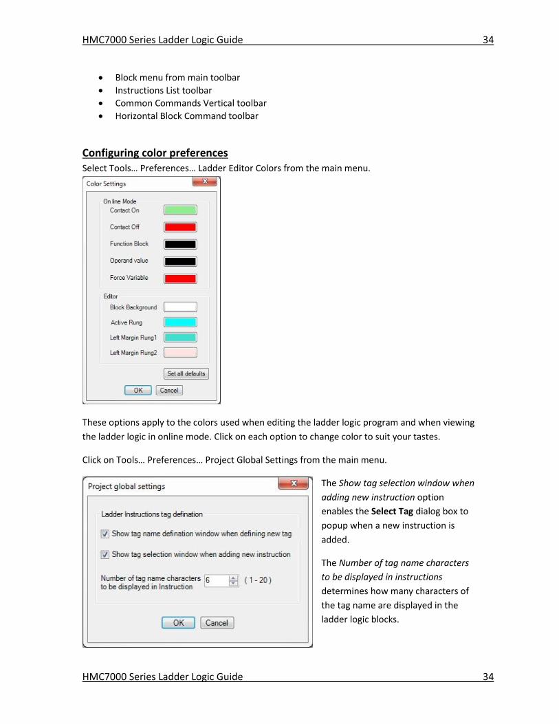
Configuring color preferences
Select Tools… Preferences… Ladder Editor Colors from the main menu.
These options apply to the colors used when editing the ladder logic program and when viewing
the ladder logic in online mode. Click on each option to change color to suit your tastes.
Click on Tools… Preferences… Project Global Settings from the main menu.
The Show tag selection window when
adding new instruction option
enables the Select Tag dialog box to
popup when a new instruction is
added.
The Number of tag name characters
to be displayed in instructions
determines how many characters of
the tag name are displayed in the
ladder logic blocks.
HMC7000 Series Ladder Logic Guide 35
HMC7000 Series Ladder Logic Guide 35
Chapter 2 - Ladder Instruction Table The tables below give a brief listing of all ladder logic instructions available. The instructions are
split into groups according to similarity of purpose. In the next chapter each instruction will be
dealt with in more detail.
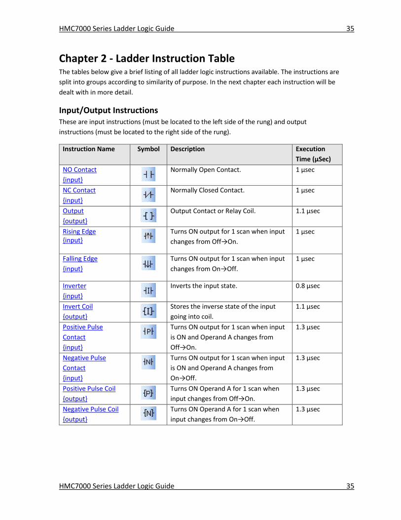
Input/Output Instructions These are input instructions (must be located to the left side of the rung) and output
instructions (must be located to the right side of the rung).
Instruction Name Symbol Description Execution
Time (μSec)
NO Contact
{input}
Normally Open Contact. 1 μsec
NC Contact
{input}
Normally Closed Contact. 1 μsec
Output
{output}
Output Contact or Relay Coil. 1.1 μsec
Rising Edge {input}
Turns ON output for 1 scan when input
changes from Off→On.
1 μsec
Falling Edge
{input}
Turns ON output for 1 scan when input
changes from On→Off.
1 μsec
Inverter
{input}
Inverts the input state. 0.8 μsec
Invert Coil
{output}
Stores the inverse state of the input
going into coil.
1.1 μsec
Positive Pulse
Contact
{input}
Turns ON output for 1 scan when input
is ON and Operand A changes from
Off→On.
1.3 μsec
Negative Pulse
Contact
{input}
Turns ON output for 1 scan when input
is ON and Operand A changes from
On→Off.
1.3 μsec
Positive Pulse Coil
{output} Turns ON Operand A for 1 scan when
input changes from Off→On.
1.3 μsec
Negative Pulse Coil
{output}
Turns ON Operand A for 1 scan when
input changes from On→Off.
1.3 μsec
HMC7000 Series Ladder Logic Guide 36
HMC7000 Series Ladder Logic Guide 36
Data Transfer Instructions These are instructions which can be used to move data from one (or more) memory location(s)
to another memory location(s).
Instruction Name Symbol Description Execution
Time (μSec)
MOV Word
Transfer data from one 16-bit register
to another.
1.9 μsec
MOV DWord
Transfer data from one 32-bit register
to another.
2.2 μsec
Invert Transfer
Transfers an inverted version of the
data in one register (ex. 1→0, and 0→1)
to another.
1.9 μsec
Table Initialize
Transfers a constant value or a value in
the specified source register (Operand
A) to a series of consecutive registers (1
to 1024) beginning with the target
register. (Operand B)
1.8 μsec to
205.3 μsec
Table Block Transfer
Transfers a series of consecutive
registers (1 to 1024) beginning with the
source register (Operand A) to a series
of consecutive registers beginning with
the target register. (Operand B)
1.7 μsec to
271.4 μsec
Table Invert Transfer
Transfers a series of consecutive
registers (1 to 1024) beginning with the
source register (Operand A) to a series
of consecutive registers beginning with
the target register (Operand B).
However, the values transferred are
inverted. (ex. 1→0, and 0→1).
1.6 μsec to
316.2 μsec
Data Exchange
The data values in the two specified
registers are exchanged or swapped.
2 μsec
Multiplexer
A particular register in a range of
registers (Operand A) is read and copied
to a target register (Operand C). Which
2.7 μsec
HMC7000 Series Ladder Logic Guide 37
HMC7000 Series Ladder Logic Guide 37
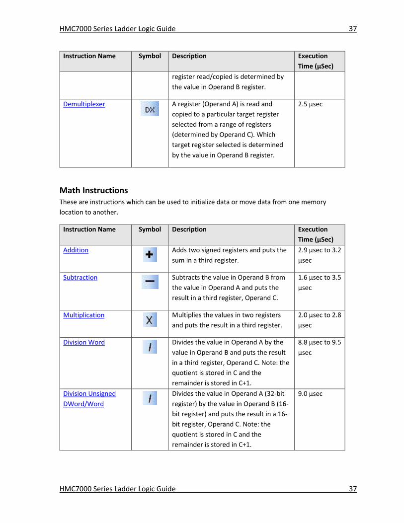
Instruction Name Symbol Description Execution
Time (μSec)
register read/copied is determined by
the value in Operand B register.
Demultiplexer
A register (Operand A) is read and
copied to a particular target register
selected from a range of registers
(determined by Operand C). Which
target register selected is determined
by the value in Operand B register.
2.5 μsec
Math Instructions These are instructions which can be used to initialize data or move data from one memory
location to another.
Instruction Name Symbol Description Execution
Time (μSec)
Addition
Adds two signed registers and puts the
sum in a third register.
2.9 μsec to 3.2
μsec
Subtraction
Subtracts the value in Operand B from
the value in Operand A and puts the
result in a third register, Operand C.
1.6 μsec to 3.5
μsec
Multiplication
Multiplies the values in two registers
and puts the result in a third register.
2.0 μsec to 2.8
μsec
Division Word
Divides the value in Operand A by the
value in Operand B and puts the result
in a third register, Operand C. Note: the
quotient is stored in C and the
remainder is stored in C+1.
8.8 μsec to 9.5
μsec
Division Unsigned
DWord/Word Divides the value in Operand A (32-bit
register) by the value in Operand B (16-
bit register) and puts the result in a 16-
bit register, Operand C. Note: the
quotient is stored in C and the
remainder is stored in C+1.
9.0 μsec
HMC7000 Series Ladder Logic Guide 38
HMC7000 Series Ladder Logic Guide 38
Instruction Name Symbol Description Execution
Time (μSec)
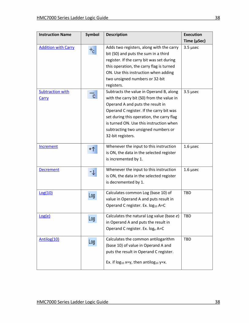
Addition with Carry
Adds two registers, along with the carry
bit (S0) and puts the sum in a third
register. If the carry bit was set during
this operation, the carry flag is turned
ON. Use this instruction when adding
two unsigned numbers or 32-bit
registers.
3.5 μsec
Subtraction with
Carry
Subtracts the value in Operand B, along
with the carry bit (S0) from the value in
Operand A and puts the result in
Operand C register. If the carry bit was
set during this operation, the carry flag
is turned ON. Use this instruction when
subtracting two unsigned numbers or
32-bit registers.
3.5 μsec
Increment
Whenever the input to this instruction
is ON, the data in the selected register
is incremented by 1.
1.6 μsec
Decrement
Whenever the input to this instruction
is ON, the data in the selected register
is decremented by 1.
1.6 μsec
Log(10)
Calculates common Log (base 10) of
value in Operand A and puts result in
Operand C register. Ex. log10 A=C
TBD
Log(e)
Calculates the natural Log value (base e)
in Operand A and puts the result in
Operand C register. Ex. loge A=C
TBD
Antilog(10)
Calculates the common antilogarithm
(base 10) of value in Operand A and
puts the result in Operand C register.
Ex. if log10 x=y, then antilog10 y=x.
TBD
HMC7000 Series Ladder Logic Guide 39
HMC7000 Series Ladder Logic Guide 39
Instruction Name Symbol Description Execution
Time (μSec)
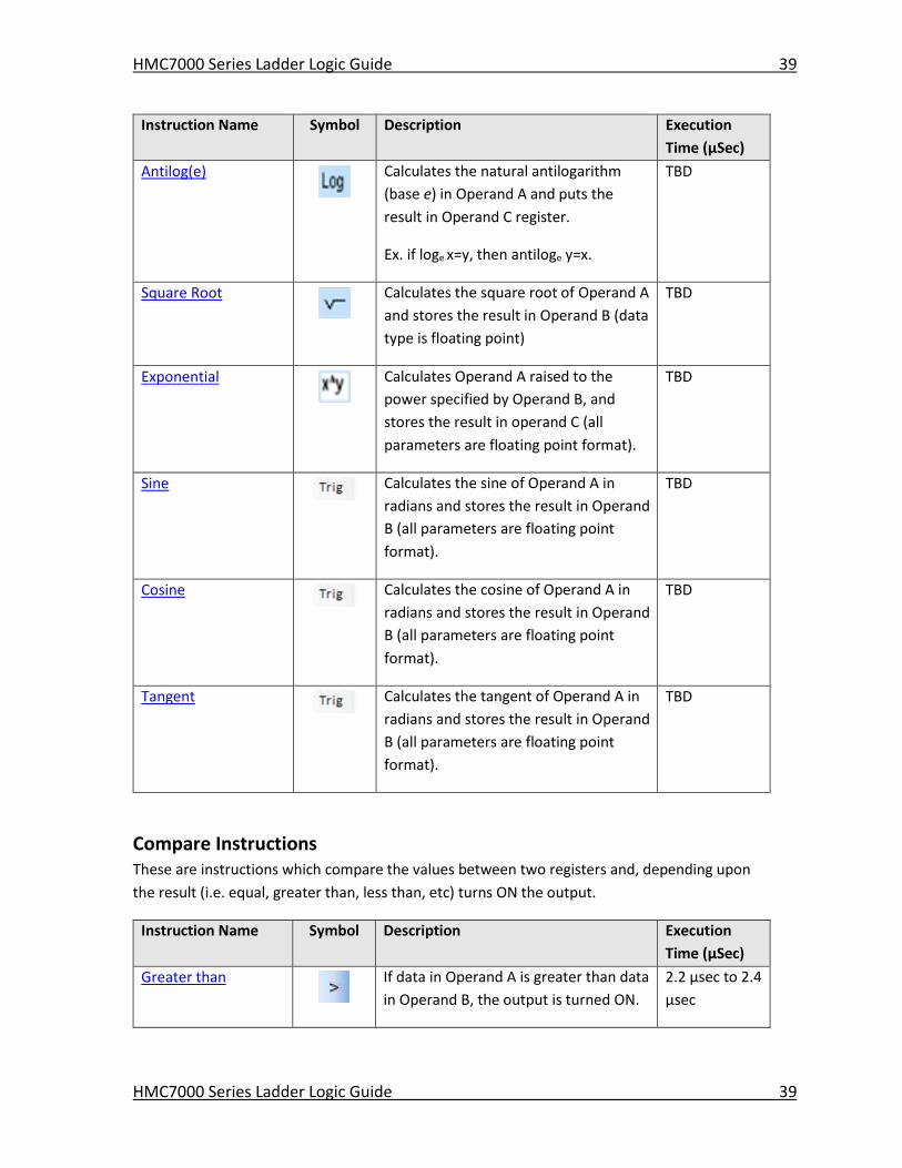
Antilog(e)
Calculates the natural antilogarithm
(base e) in Operand A and puts the
result in Operand C register.
Ex. if loge x=y, then antiloge y=x.
TBD
Square Root
Calculates the square root of Operand A
and stores the result in Operand B (data
type is floating point)
TBD
Exponential
Calculates Operand A raised to the
power specified by Operand B, and
stores the result in operand C (all
parameters are floating point format).
TBD
Sine
Calculates the sine of Operand A in
radians and stores the result in Operand
B (all parameters are floating point
format).
TBD
Cosine
Calculates the cosine of Operand A in
radians and stores the result in Operand
B (all parameters are floating point
format).
TBD
Tangent
Calculates the tangent of Operand A in
radians and stores the result in Operand
B (all parameters are floating point
format).
TBD
Compare Instructions These are instructions which compare the values between two registers and, depending upon
the result (i.e. equal, greater than, less than, etc) turns ON the output.
Instruction Name Symbol Description Execution
Time (μSec)
Greater than
If data in Operand A is greater than data
in Operand B, the output is turned ON.
2.2 μsec to 2.4
μsec
HMC7000 Series Ladder Logic Guide 40
HMC7000 Series Ladder Logic Guide 40
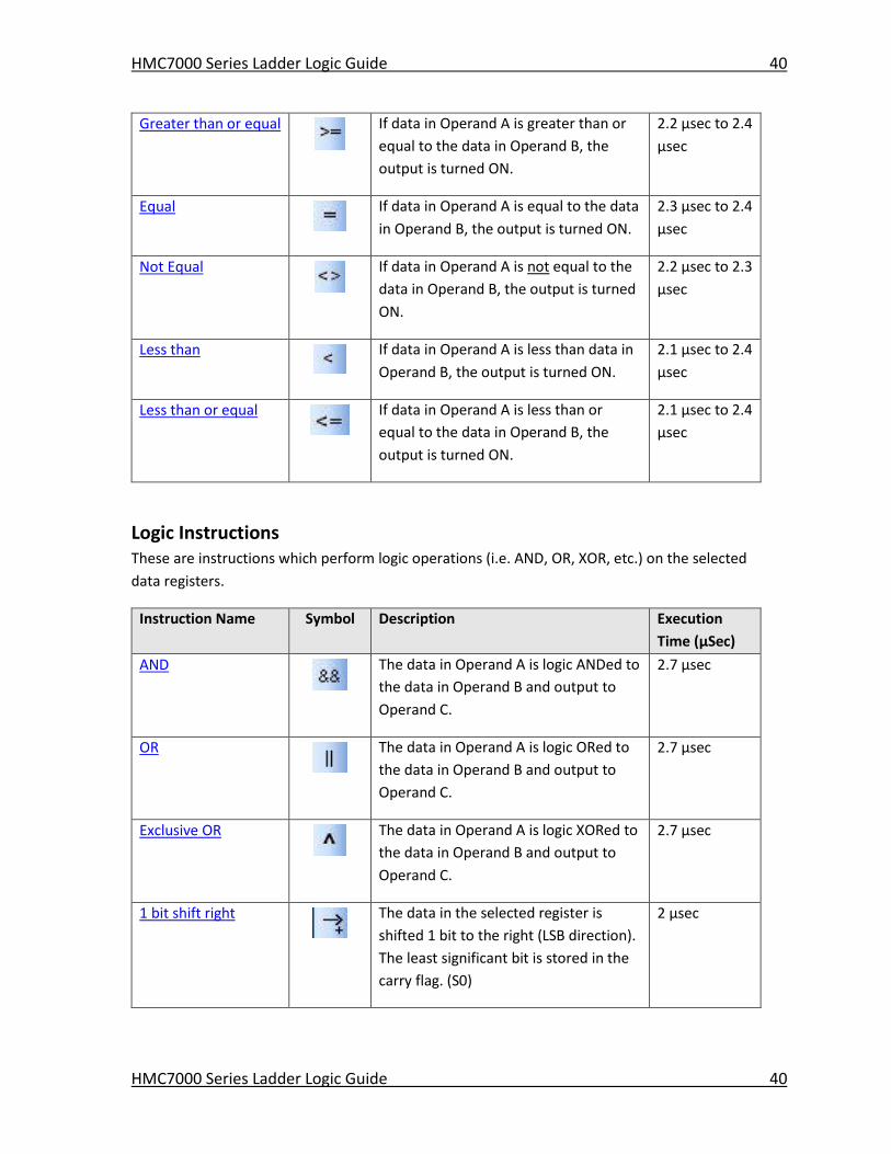
Greater than or equal
If data in Operand A is greater than or
equal to the data in Operand B, the
output is turned ON.
2.2 μsec to 2.4
μsec
Equal
If data in Operand A is equal to the data
in Operand B, the output is turned ON.
2.3 μsec to 2.4
μsec
Not Equal
If data in Operand A is not equal to the
data in Operand B, the output is turned
ON.
2.2 μsec to 2.3
μsec
Less than
If data in Operand A is less than data in
Operand B, the output is turned ON.
2.1 μsec to 2.4
μsec
Less than or equal
If data in Operand A is less than or
equal to the data in Operand B, the
output is turned ON.
2.1 μsec to 2.4
μsec
Logic Instructions These are instructions which perform logic operations (i.e. AND, OR, XOR, etc.) on the selected
data registers.
Instruction Name Symbol Description Execution
Time (μSec)
AND
The data in Operand A is logic ANDed to
the data in Operand B and output to
Operand C.
2.7 μsec
OR
The data in Operand A is logic ORed to
the data in Operand B and output to
Operand C.
2.7 μsec
Exclusive OR
The data in Operand A is logic XORed to
the data in Operand B and output to
Operand C.
2.7 μsec
1 bit shift right
The data in the selected register is
shifted 1 bit to the right (LSB direction).
The least significant bit is stored in the
carry flag. (S0)
2 μsec
HMC7000 Series Ladder Logic Guide 41
HMC7000 Series Ladder Logic Guide 41
Instruction Name Symbol Description Execution
Time (μSec)
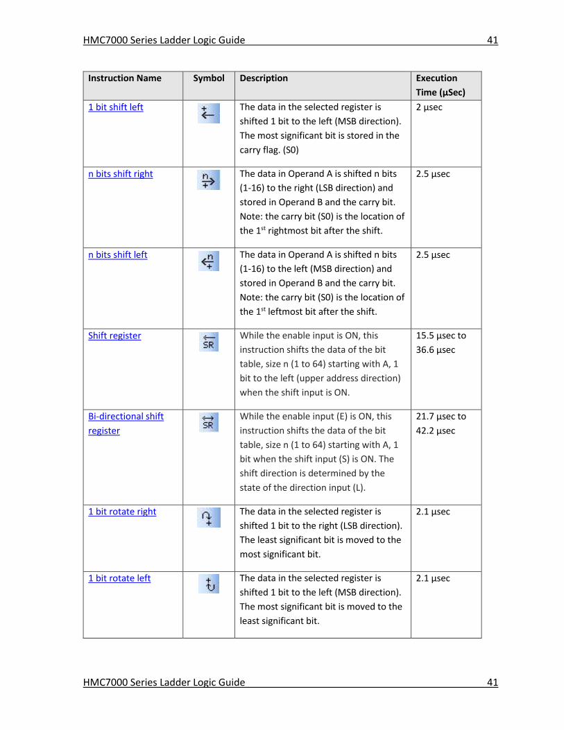
1 bit shift left
The data in the selected register is
shifted 1 bit to the left (MSB direction).
The most significant bit is stored in the
carry flag. (S0)
2 μsec
n bits shift right
The data in Operand A is shifted n bits
(1-16) to the right (LSB direction) and
stored in Operand B and the carry bit.
Note: the carry bit (S0) is the location of
the 1st rightmost bit after the shift.
2.5 μsec
n bits shift left
The data in Operand A is shifted n bits
(1-16) to the left (MSB direction) and
stored in Operand B and the carry bit.
Note: the carry bit (S0) is the location of
the 1st leftmost bit after the shift.
2.5 μsec
Shift register
While the enable input is ON, this
instruction shifts the data of the bit
table, size n (1 to 64) starting with A, 1
bit to the left (upper address direction)
when the shift input is ON.
15.5 μsec to
36.6 μsec
Bi-directional shift
register
While the enable input (E) is ON, this
instruction shifts the data of the bit
table, size n (1 to 64) starting with A, 1
bit when the shift input (S) is ON. The
shift direction is determined by the
state of the direction input (L).
21.7 μsec to
42.2 μsec
1 bit rotate right
The data in the selected register is
shifted 1 bit to the right (LSB direction).
The least significant bit is moved to the
most significant bit.
2.1 μsec
1 bit rotate left
The data in the selected register is
shifted 1 bit to the left (MSB direction).
The most significant bit is moved to the
least significant bit.
2.1 μsec
HMC7000 Series Ladder Logic Guide 42
HMC7000 Series Ladder Logic Guide 42
Instruction Name Symbol Description Execution
Time (μSec)
n bits rotate right
The data in Operand A is shifted n bits
(1 to 16) to the right (LSB direction) and
stored in Operand B.
2.4 μsec
n bits rotate left
The data in Operand A is shifted n bits
(1 to 16) to the left (MSB direction) and
stored in Operand B.
2.4 μsec
Conversion Instructions
These are instructions which convert the data from one type of format (ex. BCD, Hex, ASCII) to
another format.
Instruction Name Symbol Description Execution
Time (μSec)
Hex to ASCII
The hexadecimal data in a series of consecutive registers (1 to 32) beginning with Operand A is converted into ASCII characters and stored in consecutive registers starting with Operand B.
5.8 μsec to
87.1 μsec
ASCII to Hex
The ASCII data in a series of consecutive
registers (1 to 64) beginning with Operand A is
converted into hexadecimal characters and
stored in consecutive registers starting with
Operand B.
6.5 μsec to
64.9 μsec
Absolute Value
Computes the absolute value in Operand A
and stores in Operand B.
1.3 μsec
2’s Complement
Computes the 2’s complement value in
Operand A and stores in Operand B.
1.1 μsec
Double-word 2’s
Complement
Computes the 2’s complement value in
Operand A (and register A+1) and stores in
Operand B (and register B+1).
1.6 μsec
7 Segment decode
Converts the lower 4 data bits of Operand A into 7 segment code, and stores it in Operand B. The 7 segment code is normally used for a numeric display LED.
1.3 μsec
ASCII conversion
Converts alphanumeric characters (up to 16)
into ASCII codes, and stores them in the
designated register table, starting with
Operand B.
1.7 μsec to
5.8 μsec
HMC7000 Series Ladder Logic Guide 43
HMC7000 Series Ladder Logic Guide 43
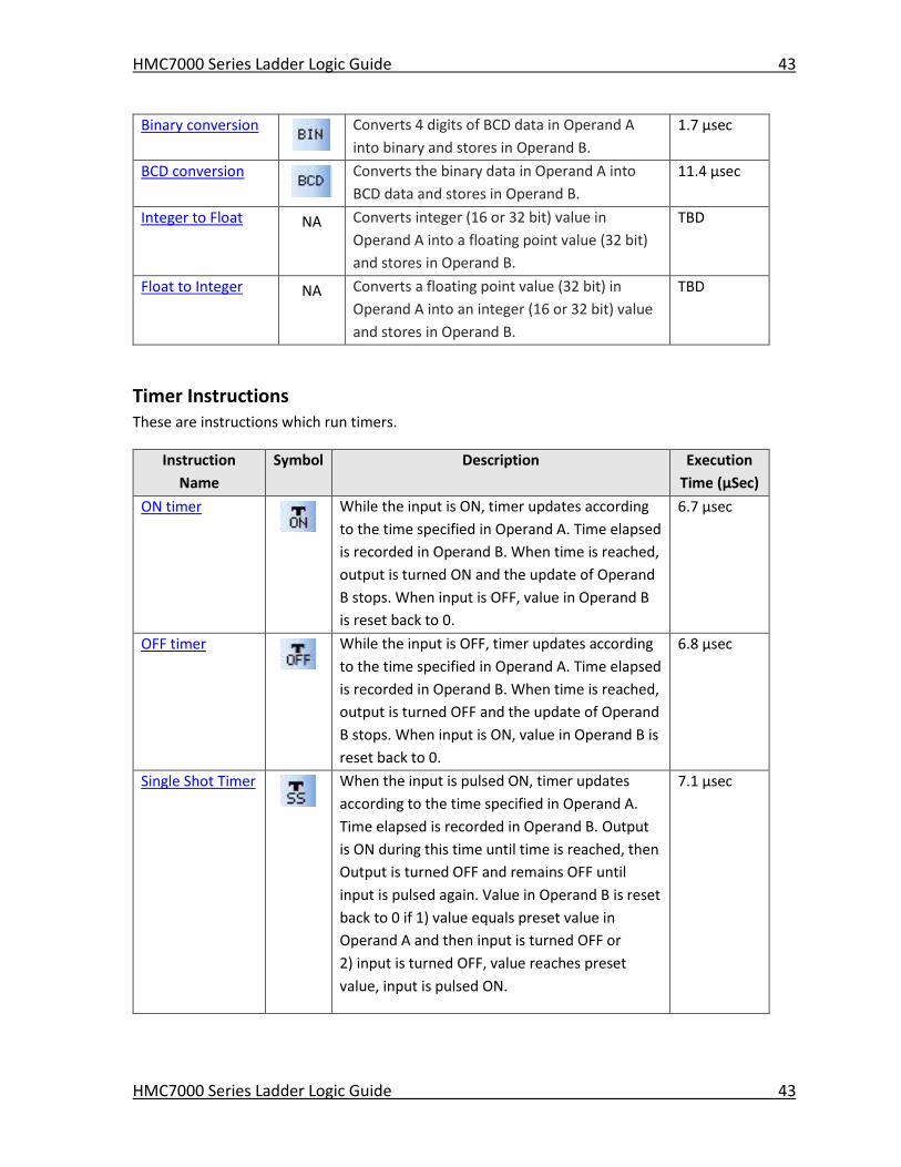
Binary conversion
Converts 4 digits of BCD data in Operand A
into binary and stores in Operand B.
1.7 μsec
BCD conversion
Converts the binary data in Operand A into
BCD data and stores in Operand B.
11.4 μsec
Integer to Float NA Converts integer (16 or 32 bit) value in
Operand A into a floating point value (32 bit)
and stores in Operand B.
TBD
Float to Integer NA Converts a floating point value (32 bit) in
Operand A into an integer (16 or 32 bit) value
and stores in Operand B.
TBD
Timer Instructions These are instructions which run timers.
Instruction
Name
Symbol Description Execution
Time (μSec)
ON timer
While the input is ON, timer updates according
to the time specified in Operand A. Time elapsed
is recorded in Operand B. When time is reached,
output is turned ON and the update of Operand
B stops. When input is OFF, value in Operand B
is reset back to 0.
6.7 μsec
OFF timer
While the input is OFF, timer updates according
to the time specified in Operand A. Time elapsed
is recorded in Operand B. When time is reached,
output is turned OFF and the update of Operand
B stops. When input is ON, value in Operand B is
reset back to 0.
6.8 μsec
Single Shot Timer
When the input is pulsed ON, timer updates
according to the time specified in Operand A.
Time elapsed is recorded in Operand B. Output
is ON during this time until time is reached, then
Output is turned OFF and remains OFF until
input is pulsed again. Value in Operand B is reset
back to 0 if 1) value equals preset value in
Operand A and then input is turned OFF or
2) input is turned OFF, value reaches preset
value, input is pulsed ON.
7.1 μsec
HMC7000 Series Ladder Logic Guide 44
HMC7000 Series Ladder Logic Guide 44
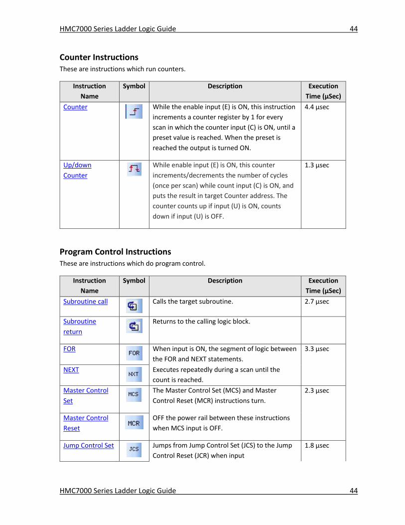
Counter Instructions These are instructions which run counters.
Instruction
Name
Symbol Description Execution
Time (μSec)
Counter
While the enable input (E) is ON, this instruction
increments a counter register by 1 for every
scan in which the counter input (C) is ON, until a
preset value is reached. When the preset is
reached the output is turned ON.
4.4 μsec
Up/down
Counter While enable input (E) is ON, this counter
increments/decrements the number of cycles
(once per scan) while count input (C) is ON, and
puts the result in target Counter address. The
counter counts up if input (U) is ON, counts
down if input (U) is OFF.
1.3 μsec
Program Control Instructions These are instructions which do program control.
Instruction
Name
Symbol Description Execution
Time (μSec)
Subroutine call
Calls the target subroutine. 2.7 μsec
Subroutine
return
Returns to the calling logic block.
FOR
When input is ON, the segment of logic between
the FOR and NEXT statements.
3.3 μsec
NEXT
Executes repeatedly during a scan until the
count is reached.
Master Control
Set
The Master Control Set (MCS) and Master
Control Reset (MCR) instructions turn.
2.3 μsec
Master Control
Reset
OFF the power rail between these instructions
when MCS input is OFF.
Jump Control Set
Jumps from Jump Control Set (JCS) to the Jump
Control Reset (JCR) when input
1.8 μsec
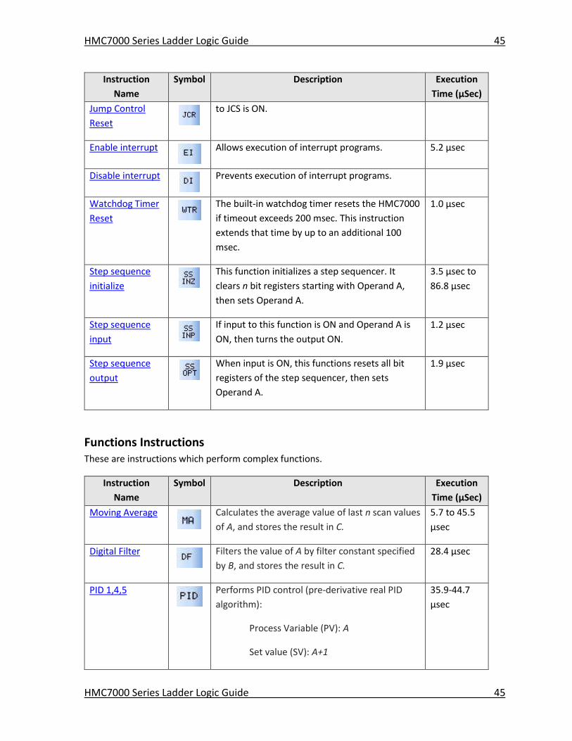
HMC7000 Series Ladder Logic Guide 45
HMC7000 Series Ladder Logic Guide 45
Instruction
Name
Symbol Description Execution
Time (μSec)
Jump Control
Reset
to JCS is ON.
Enable interrupt
Allows execution of interrupt programs. 5.2 μsec
Disable interrupt
Prevents execution of interrupt programs.
Watchdog Timer
Reset
The built-in watchdog timer resets the HMC7000
if timeout exceeds 200 msec. This instruction
extends that time by up to an additional 100
msec.
1.0 μsec
Step sequence
initialize
This function initializes a step sequencer. It
clears n bit registers starting with Operand A,
then sets Operand A.
3.5 μsec to
86.8 μsec
Step sequence
input
If input to this function is ON and Operand A is
ON, then turns the output ON.
1.2 μsec
Step sequence
output
When input is ON, this functions resets all bit
registers of the step sequencer, then sets
Operand A.
1.9 μsec
Functions Instructions These are instructions which perform complex functions.
Instruction
Name
Symbol Description Execution
Time (μSec)
Moving Average
Calculates the average value of last n scan values
of A, and stores the result in C.
5.7 to 45.5
μsec
Digital Filter
Filters the value of A by filter constant specified
by B, and stores the result in C.
28.4 μsec
PID 1,4,5
Performs PID control (pre-derivative real PID
algorithm):
Process Variable (PV): A
Set value (SV): A+1
35.9-44.7
μsec
HMC7000 Series Ladder Logic Guide 46
HMC7000 Series Ladder Logic Guide 46
Instruction
Name
Symbol Description Execution
Time (μSec)
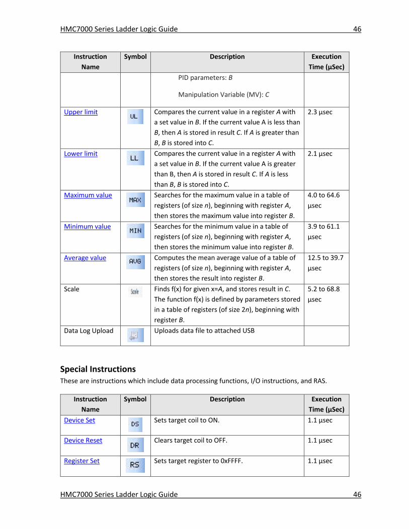
PID parameters: B
Manipulation Variable (MV): C
Upper limit
Compares the current value in a register A with
a set value in B. If the current value A is less than
B, then A is stored in result C. If A is greater than
B, B is stored into C.
2.3 μsec
Lower limit
Compares the current value in a register A with
a set value in B. If the current value A is greater
than B, then A is stored in result C. If A is less
than B, B is stored into C.
2.1 μsec
Maximum value
Searches for the maximum value in a table of
registers (of size n), beginning with register A,
then stores the maximum value into register B.
4.0 to 64.6
μsec
Minimum value
Searches for the minimum value in a table of
registers (of size n), beginning with register A,
then stores the minimum value into register B.
3.9 to 61.1
μsec
Average value
Computes the mean average value of a table of
registers (of size n), beginning with register A,
then stores the result into register B.
12.5 to 39.7
μsec
Scale
Finds f(x) for given x=A, and stores result in C.
The function f(x) is defined by parameters stored
in a table of registers (of size 2n), beginning with
register B.
5.2 to 68.8
μsec
Data Log Upload
Uploads data file to attached USB
Special Instructions These are instructions which include data processing functions, I/O instructions, and RAS.
Instruction
Name
Symbol Description Execution
Time (μSec)
Device Set
Sets target coil to ON. 1.1 μsec
Device Reset
Clears target coil to OFF. 1.1 μsec
Register Set
Sets target register to 0xFFFF. 1.1 μsec
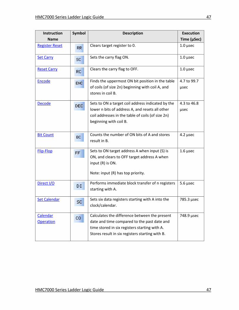
HMC7000 Series Ladder Logic Guide 47
HMC7000 Series Ladder Logic Guide 47
Instruction
Name
Symbol Description Execution
Time (μSec)
Register Reset
Clears target register to 0. 1.0 μsec
Set Carry
Sets the carry flag ON. 1.0 μsec
Reset Carry
Clears the carry flag to OFF. 1.0 μsec
Encode
Finds the uppermost ON bit position in the table
of coils (of size 2n) beginning with coil A, and
stores in coil B.
4.7 to 99.7
μsec
Decode
Sets to ON a target coil address indicated by the
lower n bits of address A, and resets all other
coil addresses in the table of coils (of size 2n)
beginning with coil B.
4.3 to 46.8
μsec
Bit Count
Counts the number of ON bits of A and stores
result in B.
4.2 μsec
Flip-Flop
Sets to ON target address A when input (S) is
ON, and clears to OFF target address A when
input (R) is ON.
Note: input (R) has top priority.
1.6 μsec
Direct I/O
Performs immediate block transfer of n registers
starting with A.
5.6 μsec
Set Calendar
Sets six data registers starting with A into the
clock/calendar.
785.3 μsec
Calendar
Operation
Calculates the difference between the present
date and time compared to the past date and
time stored in six registers starting with A.
Stores result in six registers starting with B.
748.9 μsec
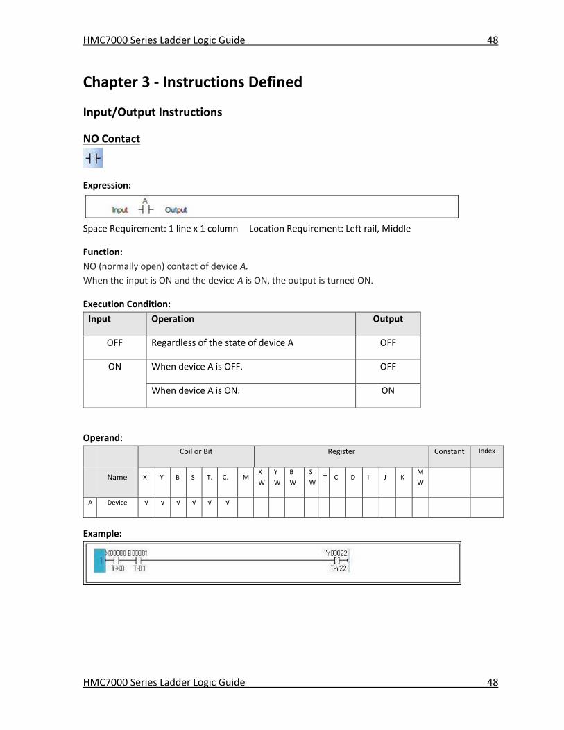
HMC7000 Series Ladder Logic Guide 48
HMC7000 Series Ladder Logic Guide 48
Chapter 3 - Instructions Defined
Input/Output Instructions
NO Contact
Expression:
Space Requirement: 1 line x 1 column Location Requirement: Left rail, Middle
Function:
NO (normally open) contact of device A.
When the input is ON and the device A is ON, the output is turned ON.
Execution Condition:
Input Operation Output
OFF Regardless of the state of device A OFF
ON When device A is OFF. OFF
When device A is ON. ON
Operand:
Coil or Bit Register Constant Index
Name X Y B S T. C. M
X
W
Y
W
B
W
S
W T C D I J K
M
W
A Device √ √ √ √ √ √
Example:
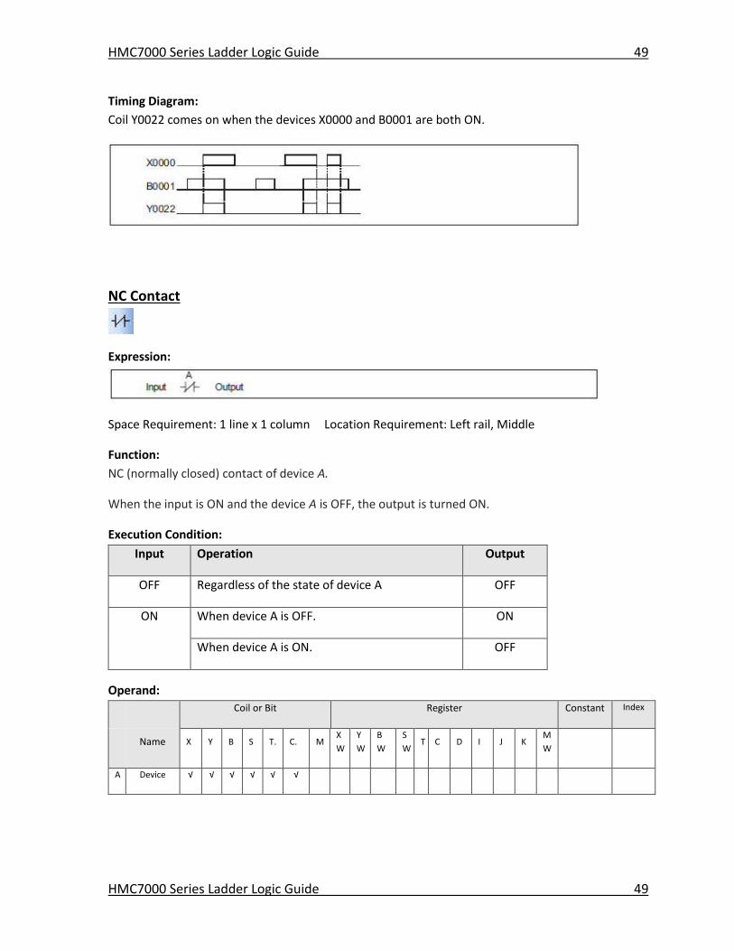
HMC7000 Series Ladder Logic Guide 49
HMC7000 Series Ladder Logic Guide 49
Timing Diagram:
Coil Y0022 comes on when the devices X0000 and B0001 are both ON.
NC Contact
Expression:
Space Requirement: 1 line x 1 column Location Requirement: Left rail, Middle
Function:
NC (normally closed) contact of device A.
When the input is ON and the device A is OFF, the output is turned ON.
Execution Condition:
Input Operation Output
OFF Regardless of the state of device A OFF
ON When device A is OFF. ON
When device A is ON. OFF
Operand:
Coil or Bit Register Constant Index
Name X Y B S T. C. M
X
W
Y
W
B
W
S
W T C D I J K
M
W
A Device √ √ √ √ √ √
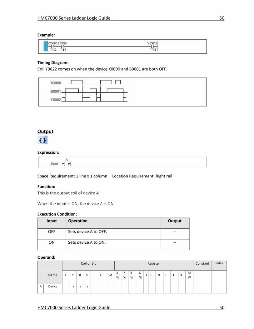
HMC7000 Series Ladder Logic Guide 50
HMC7000 Series Ladder Logic Guide 50
Example:
Timing Diagram:
Coil Y0022 comes on when the device X0000 and B0001 are both OFF.
Output
Expression:
Space Requirement: 1 line x 1 column Location Requirement: Right rail
Function:
This is the output coil of device A.
When the input is ON, the device A is ON.
Execution Condition:
Input Operation Output
OFF Sets device A to OFF. --
ON Sets device A to ON. --
Operand:
Coil or Bit Register Constant Index
Name X Y B S T. C. M
X
W
Y
W
B
W
S
W T C D I J K
M
W
A Device √ √ √
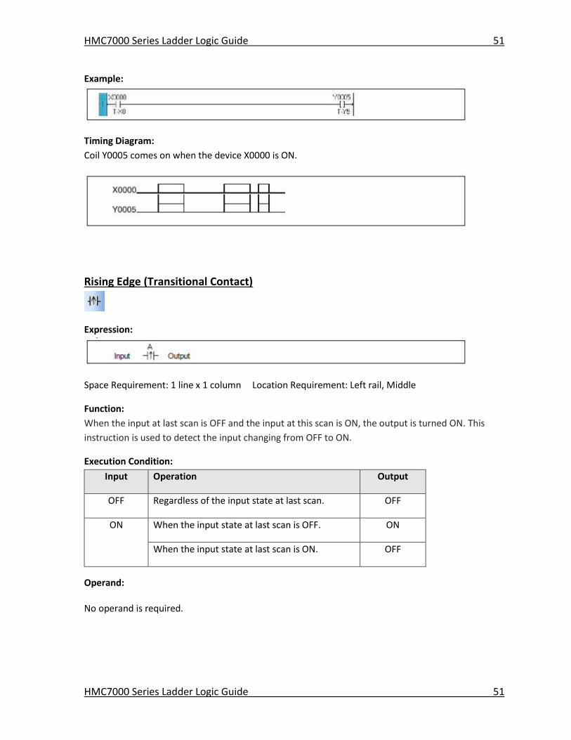
HMC7000 Series Ladder Logic Guide 51
HMC7000 Series Ladder Logic Guide 51
Example:
Timing Diagram:
Coil Y0005 comes on when the device X0000 is ON.
Rising Edge (Transitional Contact)
Expression:
Space Requirement: 1 line x 1 column Location Requirement: Left rail, Middle
Function:
When the input at last scan is OFF and the input at this scan is ON, the output is turned ON. This
instruction is used to detect the input changing from OFF to ON.
Execution Condition:
Input Operation Output
OFF Regardless of the input state at last scan. OFF
ON When the input state at last scan is OFF. ON
When the input state at last scan is ON. OFF
Operand:
No operand is required.
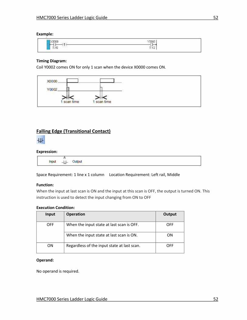
HMC7000 Series Ladder Logic Guide 52
HMC7000 Series Ladder Logic Guide 52
Example:
Timing Diagram:
Coil Y0002 comes ON for only 1 scan when the device X0000 comes ON.
Falling Edge (Transitional Contact)
Expression:
Space Requirement: 1 line x 1 column Location Requirement: Left rail, Middle
Function:
When the input at last scan is ON and the input at this scan is OFF, the output is turned ON. This
instruction is used to detect the input changing from ON to OFF
Execution Condition:
Input Operation Output
OFF When the input state at last scan is OFF. OFF
When the input state at last scan is ON. ON
ON Regardless of the input state at last scan. OFF
Operand:
No operand is required.
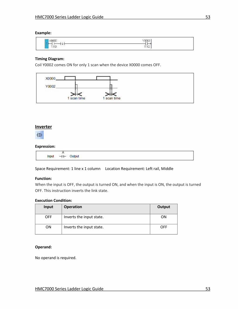
HMC7000 Series Ladder Logic Guide 53
HMC7000 Series Ladder Logic Guide 53
Example:
Timing Diagram:
Coil Y0002 comes ON for only 1 scan when the device X0000 comes OFF.
Inverter
Expression:
Space Requirement: 1 line x 1 column Location Requirement: Left rail, Middle
Function:
When the input is OFF, the output is turned ON, and when the input is ON, the output is turned
OFF. This instruction inverts the link state.
Execution Condition:
Input Operation Output
OFF Inverts the input state. ON
ON Inverts the input state. OFF
Operand:
No operand is required.
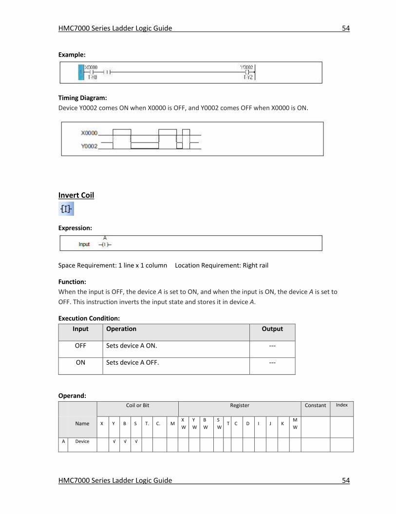
HMC7000 Series Ladder Logic Guide 54
HMC7000 Series Ladder Logic Guide 54
Example:
Timing Diagram:
Device Y0002 comes ON when X0000 is OFF, and Y0002 comes OFF when X0000 is ON.
Invert Coil
Expression:
Space Requirement: 1 line x 1 column Location Requirement: Right rail
Function:
When the input is OFF, the device A is set to ON, and when the input is ON, the device A is set to
OFF. This instruction inverts the input state and stores it in device A.
Execution Condition:
Input Operation Output
OFF Sets device A ON. ---
ON Sets device A OFF. ---
Operand:
Coil or Bit Register Constant Index
Name X Y B S T. C. M
X
W
Y
W
B
W
S
W T C D I J K
M
W
A Device √ √ √
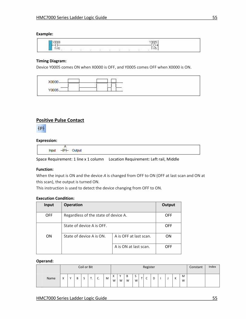
HMC7000 Series Ladder Logic Guide 55
HMC7000 Series Ladder Logic Guide 55
Example:
Timing Diagram:
Device Y0005 comes ON when X0000 is OFF, and Y0005 comes OFF when X0000 is ON.
Positive Pulse Contact
Expression:
Space Requirement: 1 line x 1 column Location Requirement: Left rail, Middle
Function:
When the input is ON and the device A is changed from OFF to ON (OFF at last scan and ON at
this scan), the output is turned ON.
This instruction is used to detect the device changing from OFF to ON.
Execution Condition:
Input Operation Output
OFF Regardless of the state of device A. OFF
State of device A is OFF. OFF
ON State of device A is ON. A is OFF at last scan. ON
A is ON at last scan. OFF
Operand:
Coil or Bit Register Constant Index
Name X Y B S T. C. M
X
W
Y
W
B
W
S
W T C D I J K
M
W
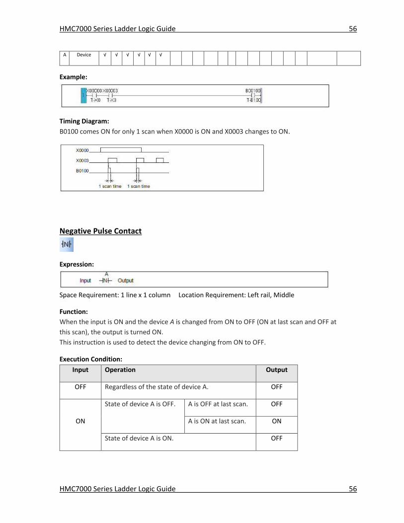
HMC7000 Series Ladder Logic Guide 56
HMC7000 Series Ladder Logic Guide 56
A Device √ √ √ √ √ √
Example:
Timing Diagram:
B0100 comes ON for only 1 scan when X0000 is ON and X0003 changes to ON.
Negative Pulse Contact
Expression:
Space Requirement: 1 line x 1 column Location Requirement: Left rail, Middle
Function:
When the input is ON and the device A is changed from ON to OFF (ON at last scan and OFF at
this scan), the output is turned ON.
This instruction is used to detect the device changing from ON to OFF.
Execution Condition:
Input Operation Output
OFF Regardless of the state of device A. OFF
State of device A is OFF. A is OFF at last scan. OFF
ON A is ON at last scan. ON
State of device A is ON. OFF
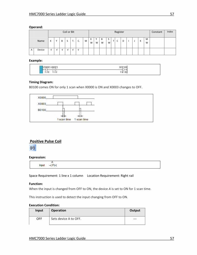
HMC7000 Series Ladder Logic Guide 57
HMC7000 Series Ladder Logic Guide 57
Operand:
Coil or Bit Register Constant Index
Name X Y B S T. C. M
X
W
Y
W
B
W
S
W T C D I J K
M
W
A Device √ √ √ √ √ √
Example:
Timing Diagram:
B0100 comes ON for only 1 scan when X0000 is ON and X0003 changes to OFF.
Positive Pulse Coil
Expression:
Space Requirement: 1 line x 1 column Location Requirement: Right rail
Function:
When the input is changed from OFF to ON, the device A is set to ON for 1 scan time.
This instruction is used to detect the input changing from OFF to ON.
Execution Condition:
Input Operation Output
OFF Sets device A to OFF. ---
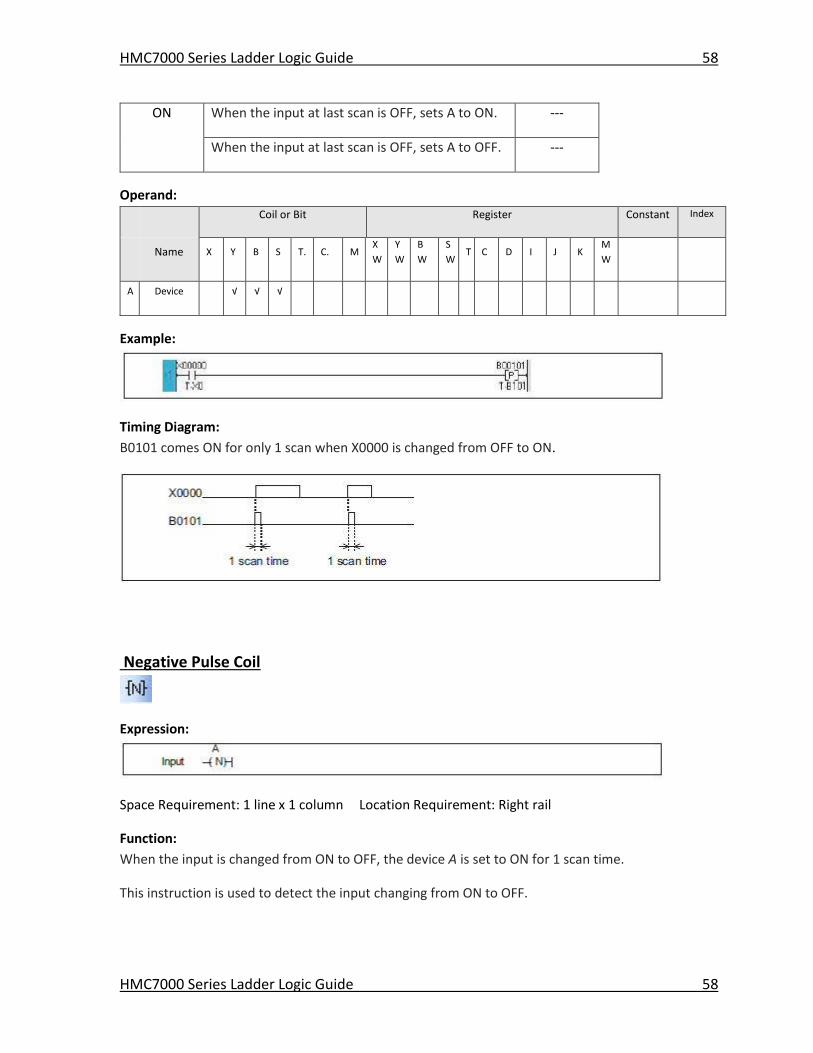
HMC7000 Series Ladder Logic Guide 58
HMC7000 Series Ladder Logic Guide 58
ON When the input at last scan is OFF, sets A to ON. ---
When the input at last scan is OFF, sets A to OFF. ---
Operand:
Coil or Bit Register Constant Index
Name X Y B S T. C. M
X
W
Y
W
B
W
S
W T C D I J K
M
W
A Device √ √ √
Example:
Timing Diagram:
B0101 comes ON for only 1 scan when X0000 is changed from OFF to ON.
Negative Pulse Coil
Expression:
Space Requirement: 1 line x 1 column Location Requirement: Right rail
Function:
When the input is changed from ON to OFF, the device A is set to ON for 1 scan time.
This instruction is used to detect the input changing from ON to OFF.
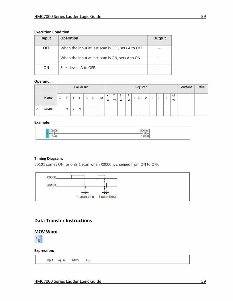
HMC7000 Series Ladder Logic Guide 59
HMC7000 Series Ladder Logic Guide 59
Execution Condition:
Input Operation Output
OFF When the input at last scan is OFF, sets A to OFF. ---
When the input at last scan is ON, sets A to ON. ---
ON Sets device A to OFF. ---
Operand:
Coil or Bit Register Constant Index
Name X Y B S T. C. M
X
W
Y
W
B
W
S
W T C D I J K
M
W
A Device √ √ √
Example:
Timing Diagram:
B0101 comes ON for only 1 scan when X0000 is changed from ON to OFF.
Data Transfer Instructions
MOV Word
Expression:
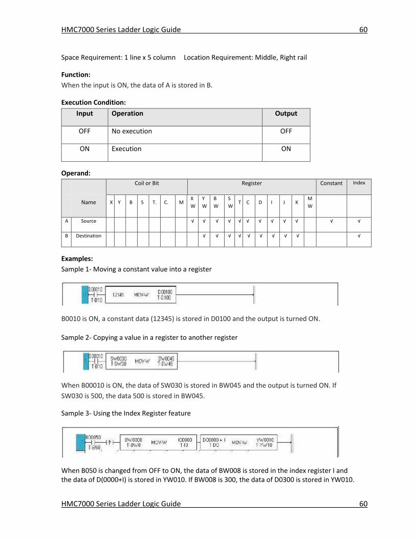
HMC7000 Series Ladder Logic Guide 60
HMC7000 Series Ladder Logic Guide 60
Space Requirement: 1 line x 5 column Location Requirement: Middle, Right rail
Function:
When the input is ON, the data of A is stored in B.
Execution Condition:
Input Operation Output
OFF No execution OFF
ON Execution ON
Operand:
Coil or Bit Register Constant Index
Name X Y B S T. C. M
X
W
Y
W
B
W
S
W T C D I J K
M
W
A Source √ √ √ √ √ √ √ √ √ √ √ √
B Destination √ √ √ √ √ √ √ √ √ √
Examples:
Sample 1- Moving a constant value into a register
B0010 is ON, a constant data (12345) is stored in D0100 and the output is turned ON.
Sample 2- Copying a value in a register to another register
When B00010 is ON, the data of SW030 is stored in BW045 and the output is turned ON. If
SW030 is 500, the data 500 is stored in BW045.
Sample 3- Using the Index Register feature
When B050 is changed from OFF to ON, the data of BW008 is stored in the index register I and the data of D(0000+I) is stored in YW010. If BW008 is 300, the data of D0300 is stored in YW010.

HMC7000 Series Ladder Logic Guide 61
HMC7000 Series Ladder Logic Guide 61
MOV DWord
Expression:
Space Requirement: 1 line x 5 column Location Requirement: Middle, Right rail
Function:
When the input is ON, the double-word (32-bit) data of A+1× A is stored in double-word register
B+1× B. The data range is -2147483648 to 2147483647.
Execution Condition:
Input Operation Output
OFF No execution OFF
ON Execution ON
Operand:
Coil or Bit Register Constant Index
Name X Y B S T. C. M
X
W
Y
W
B
W
S
W T C D I J K
M
W
A Source √ √ √ √ √ √ √ √ √ √ √ √
B Destination √ √ √ √ √ √ √ √ √ √
Example:
When B011 is ON, a double-word data of D0101×D0100 is stored in BW17×BW16 and the output is turned ON. If D0101×D0100 is 1234567, the data 1234567 is stored in BW17×BW16.
Invert Transfer
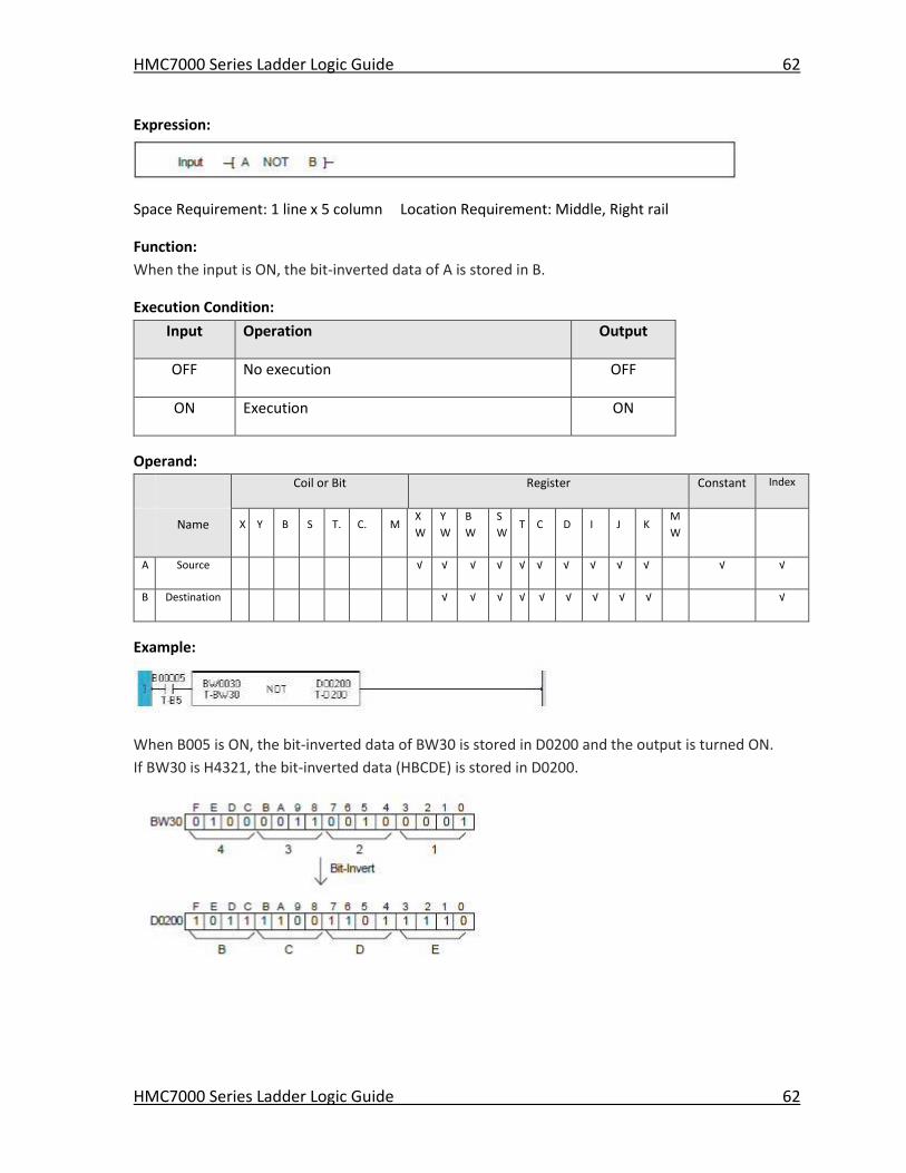
HMC7000 Series Ladder Logic Guide 62
HMC7000 Series Ladder Logic Guide 62
Expression:
Space Requirement: 1 line x 5 column Location Requirement: Middle, Right rail
Function:
When the input is ON, the bit-inverted data of A is stored in B.
Execution Condition:
Input Operation Output
OFF No execution OFF
ON Execution ON
Operand:
Coil or Bit Register Constant Index
Name X Y B S T. C. M
X
W
Y
W
B
W
S
W T C D I J K
M
W
A Source √ √ √ √ √ √ √ √ √ √ √ √
B Destination √ √ √ √ √ √ √ √ √ √
Example:
When B005 is ON, the bit-inverted data of BW30 is stored in D0200 and the output is turned ON.
If BW30 is H4321, the bit-inverted data (HBCDE) is stored in D0200.
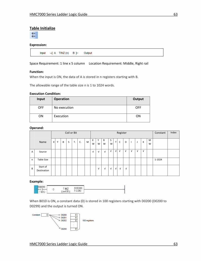
HMC7000 Series Ladder Logic Guide 63
HMC7000 Series Ladder Logic Guide 63
Table Initialize
Expression:
Space Requirement: 1 line x 5 column Location Requirement: Middle, Right rail
Function:
When the input is ON, the data of A is stored in n registers starting with B.
The allowable range of the table size n is 1 to 1024 words.
Execution Condition:
Input Operation Output
OFF No execution OFF
ON Execution ON
Operand:
Coil or Bit Register Constant Index
Name X Y B S T. C. M
X
W
Y
W
B
W
S
W T C D I J K
M
W
A Source √ √ √ √ √ √ √ √ √ √
n Table Size 1-1024
B Start of
Destination √ √ √ √ √ √
Example:
When B010 is ON, a constant data (0) is stored in 100 registers starting with D0200 (D0200 to
D0299) and the output is turned ON.
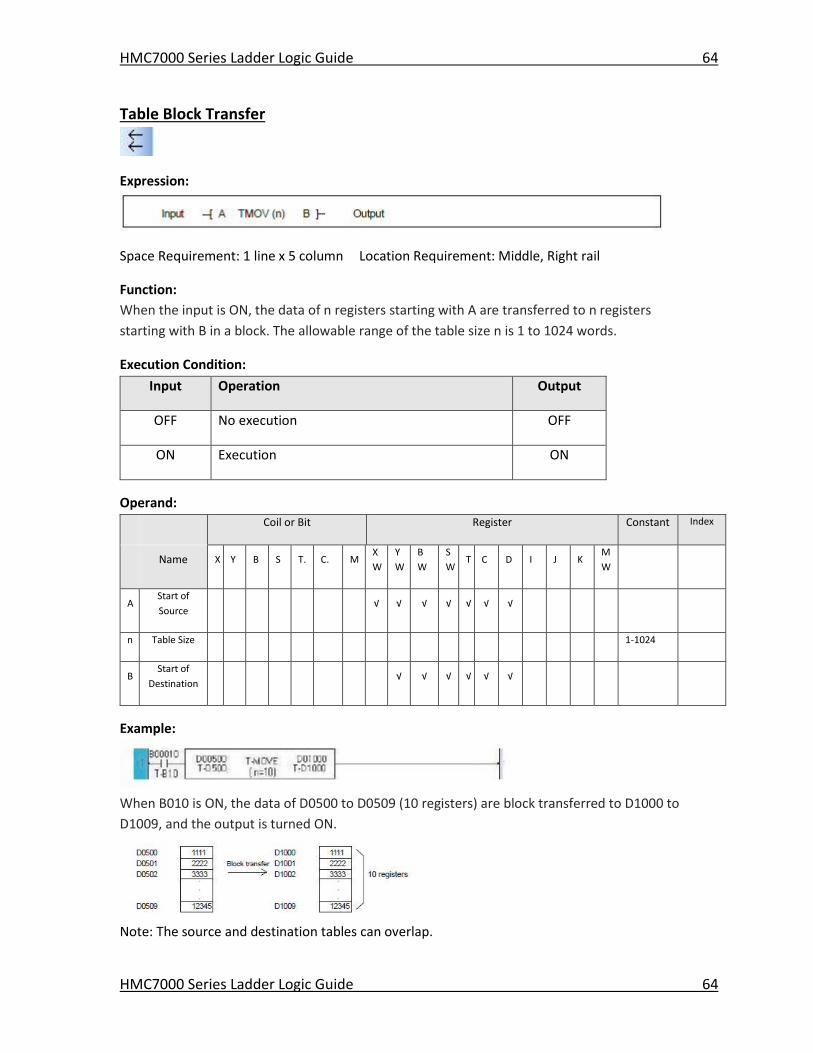
HMC7000 Series Ladder Logic Guide 64
HMC7000 Series Ladder Logic Guide 64
Table Block Transfer
Expression:
Space Requirement: 1 line x 5 column Location Requirement: Middle, Right rail
Function:
When the input is ON, the data of n registers starting with A are transferred to n registers
starting with B in a block. The allowable range of the table size n is 1 to 1024 words.
Execution Condition:
Input Operation Output
OFF No execution OFF
ON Execution ON
Operand:
Coil or Bit Register Constant Index
Name X Y B S T. C. M
X
W
Y
W
B
W
S
W T C D I J K
M
W
A Start of
Source √ √ √ √ √ √ √
n Table Size 1-1024
B Start of
Destination √ √ √ √ √ √
Example:
When B010 is ON, the data of D0500 to D0509 (10 registers) are block transferred to D1000 to
D1009, and the output is turned ON.
Note: The source and destination tables can overlap.
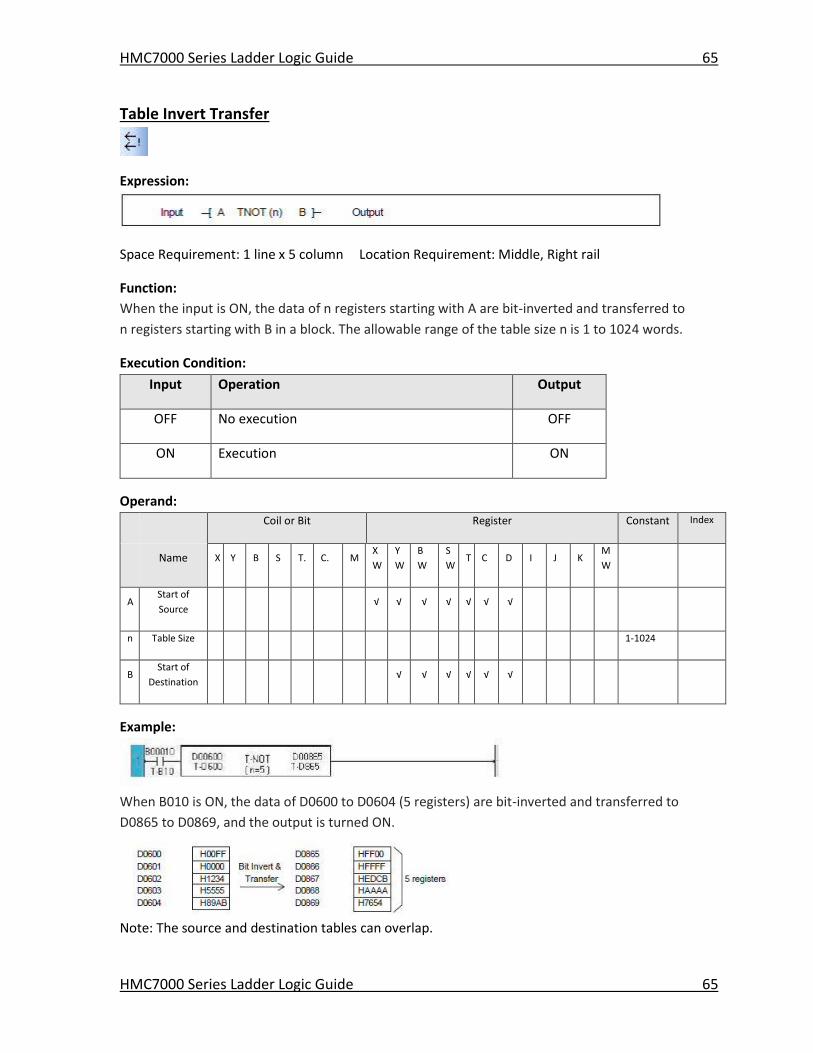
HMC7000 Series Ladder Logic Guide 65
HMC7000 Series Ladder Logic Guide 65
Table Invert Transfer
Expression:
Space Requirement: 1 line x 5 column Location Requirement: Middle, Right rail
Function:
When the input is ON, the data of n registers starting with A are bit-inverted and transferred to
n registers starting with B in a block. The allowable range of the table size n is 1 to 1024 words.
Execution Condition:
Input Operation Output
OFF No execution OFF
ON Execution ON
Operand:
Coil or Bit Register Constant Index
Name X Y B S T. C. M
X
W
Y
W
B
W
S
W T C D I J K
M
W
A Start of
Source √ √ √ √ √ √ √
n Table Size 1-1024
B Start of
Destination √ √ √ √ √ √
Example:
When B010 is ON, the data of D0600 to D0604 (5 registers) are bit-inverted and transferred to
D0865 to D0869, and the output is turned ON.
Note: The source and destination tables can overlap.
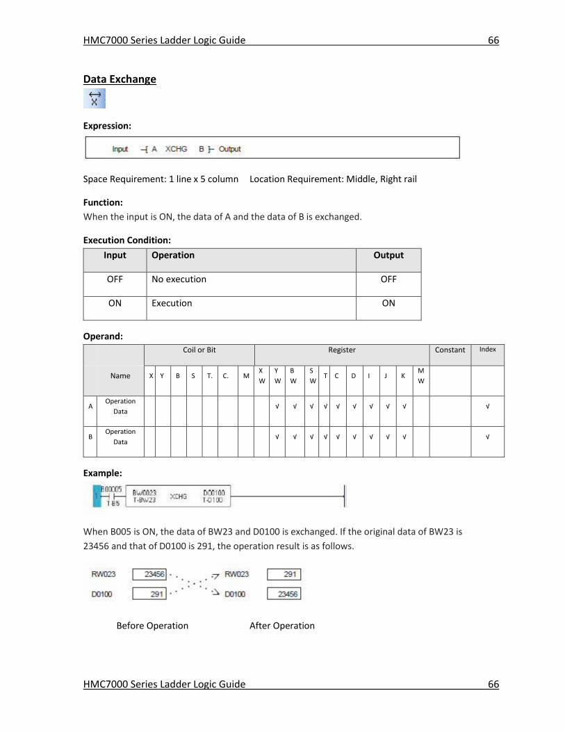
HMC7000 Series Ladder Logic Guide 66
HMC7000 Series Ladder Logic Guide 66
Data Exchange
Expression:
Space Requirement: 1 line x 5 column Location Requirement: Middle, Right rail
Function:
When the input is ON, the data of A and the data of B is exchanged.
Execution Condition:
Input Operation Output
OFF No execution OFF
ON Execution ON
Operand:
Coil or Bit Register Constant Index
Name X Y B S T. C. M
X
W
Y
W
B
W
S
W T C D I J K
M
W
A Operation
Data √ √ √ √ √ √ √ √ √ √
B Operation
Data √ √ √ √ √ √ √ √ √
√
Example:
When B005 is ON, the data of BW23 and D0100 is exchanged. If the original data of BW23 is
23456 and that of D0100 is 291, the operation result is as follows.
Before Operation After Operation
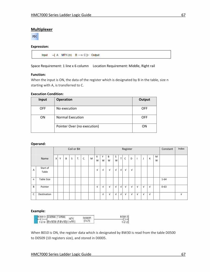
HMC7000 Series Ladder Logic Guide 67
HMC7000 Series Ladder Logic Guide 67
Multiplexer
Expression:
Space Requirement: 1 line x 6 column Location Requirement: Middle, Right rail
Function:
When the input is ON, the data of the register which is designated by B in the table, size n
starting with A, is transferred to C.
Execution Condition:
Input Operation Output
OFF No execution OFF
ON Normal Execution OFF
Pointer Over (no execution) ON
Operand:
Coil or Bit Register Constant Index
Name X Y B S T. C. M
X
W
Y
W
B
W
S
W T C D I J K
M
W
A Start of
Table √ √ √ √ √ √ √
n Table Size 1-64
B Pointer √ √ √ √ √ √ √ √ √ √ 0-63
C Destination √ √ √ √ √ √ √ √ √ √
Example:
When B010 is ON, the register data which is designated by BW30 is read from the table D0500
to D0509 (10 registers size), and stored in D0005.
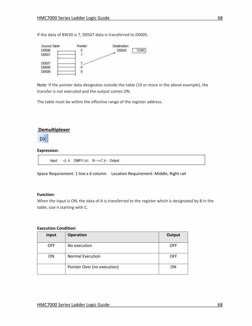
HMC7000 Series Ladder Logic Guide 68
HMC7000 Series Ladder Logic Guide 68
If the data of BW30 is 7, D0507 data is transferred to D0005.
Note: If the pointer data designates outside the table (10 or more in the above example), the
transfer is not executed and the output comes ON.
The table must be within the effective range of the register address.
Demultiplexer
Expression:
Space Requirement: 1 line x 6 column Location Requirement: Middle, Right rail
Function:
When the input is ON, the data of A is transferred to the register which is designated by B in the
table, size n starting with C.
Execution Condition:
Input Operation Output
OFF No execution OFF
ON Normal Execution OFF
Pointer Over (no execution) ON
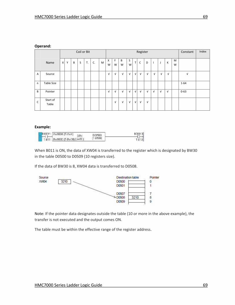
HMC7000 Series Ladder Logic Guide 69
HMC7000 Series Ladder Logic Guide 69
Operand:
Coil or Bit Register Constant Index
Name X Y B S T. C. M
X
W
Y
W
B
W
S
W T C D I J K
M
W
A Source √ √ √ √ √ √ √ √ √ √ √
n Table Size 1-64
B Pointer √ √ √ √ √ √ √ √ √ √ 0-63
C Start of
Table √ √ √ √ √ √
Example:
When B011 is ON, the data of XW04 is transferred to the register which is designated by BW30
in the table D0500 to D0509 (10 registers size).
If the data of BW30 is 8, XW04 data is transferred to D0508.
Note: If the pointer data designates outside the table (10 or more in the above example), the
transfer is not executed and the output comes ON.
The table must be within the effective range of the register address.
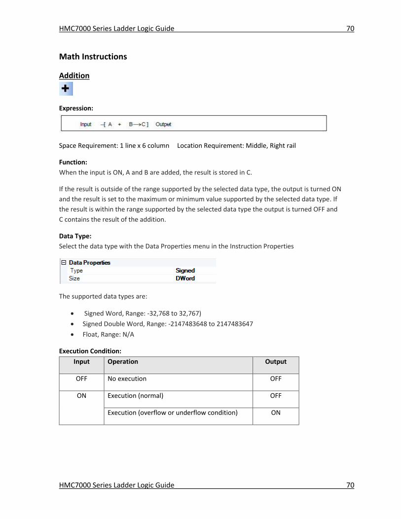
HMC7000 Series Ladder Logic Guide 70
HMC7000 Series Ladder Logic Guide 70
Math Instructions
Addition
Expression:
Space Requirement: 1 line x 6 column Location Requirement: Middle, Right rail
Function:
When the input is ON, A and B are added, the result is stored in C.
If the result is outside of the range supported by the selected data type, the output is turned ON
and the result is set to the maximum or minimum value supported by the selected data type. If
the result is within the range supported by the selected data type the output is turned OFF and
C contains the result of the addition.
Data Type:
Select the data type with the Data Properties menu in the Instruction Properties
The supported data types are:
Signed Word, Range: -32,768 to 32,767)
Signed Double Word, Range: -2147483648 to 2147483647
Float, Range: N/A
Execution Condition:
Input Operation Output
OFF No execution OFF
ON Execution (normal) OFF
Execution (overflow or underflow condition) ON
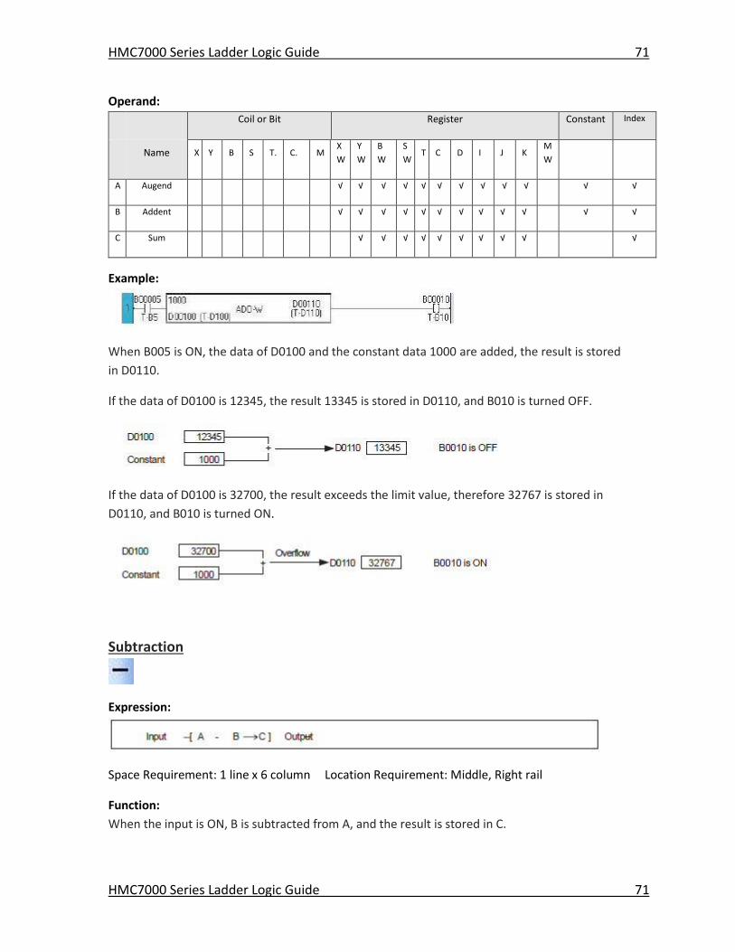
HMC7000 Series Ladder Logic Guide 71
HMC7000 Series Ladder Logic Guide 71
Operand:
Coil or Bit Register Constant Index
Name X Y B S T. C. M
X
W
Y
W
B
W
S
W T C D I J K
M
W
A Augend √ √ √ √ √ √ √ √ √ √ √ √
B Addent √ √ √ √ √ √ √ √ √ √ √ √
C Sum √ √ √ √ √ √ √ √ √ √
Example:
When B005 is ON, the data of D0100 and the constant data 1000 are added, the result is stored
in D0110.
If the data of D0100 is 12345, the result 13345 is stored in D0110, and B010 is turned OFF.
If the data of D0100 is 32700, the result exceeds the limit value, therefore 32767 is stored in
D0110, and B010 is turned ON.
Subtraction
Expression:
Space Requirement: 1 line x 6 column Location Requirement: Middle, Right rail
Function:
When the input is ON, B is subtracted from A, and the result is stored in C.
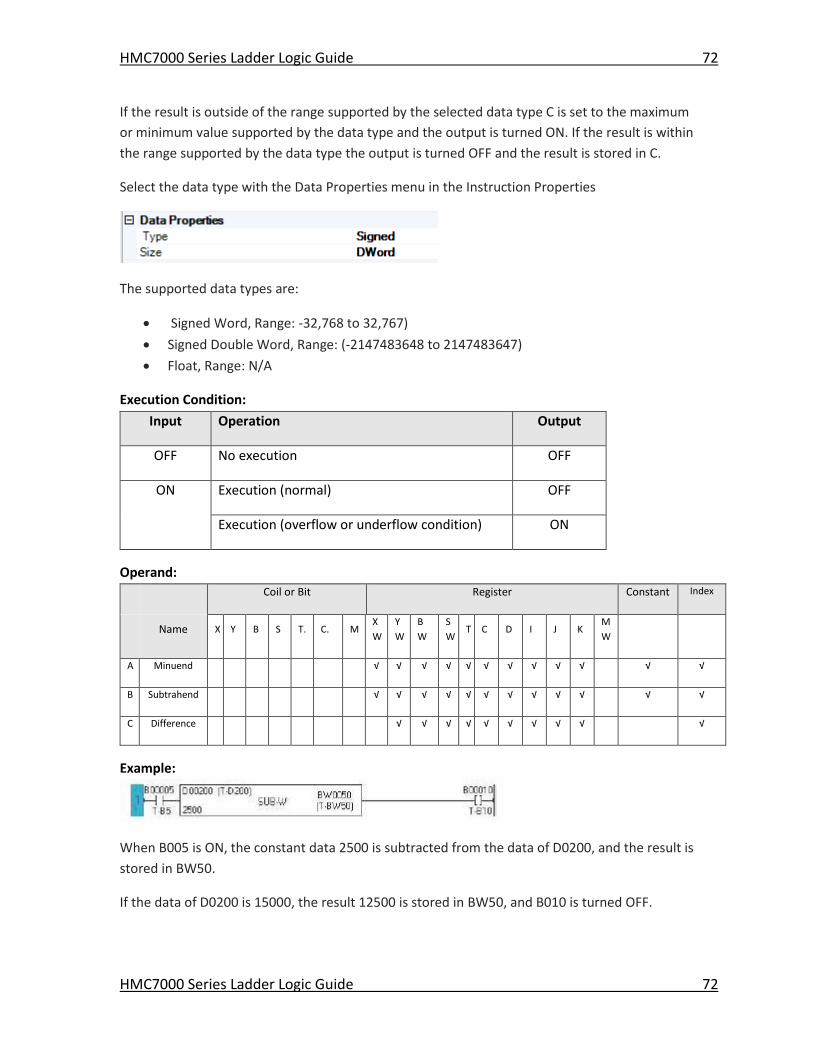
HMC7000 Series Ladder Logic Guide 72
HMC7000 Series Ladder Logic Guide 72
If the result is outside of the range supported by the selected data type C is set to the maximum
or minimum value supported by the data type and the output is turned ON. If the result is within
the range supported by the data type the output is turned OFF and the result is stored in C.
Select the data type with the Data Properties menu in the Instruction Properties
The supported data types are:
Signed Word, Range: -32,768 to 32,767)
Signed Double Word, Range: (-2147483648 to 2147483647)
Float, Range: N/A
Execution Condition:
Input Operation Output
OFF No execution OFF
ON Execution (normal) OFF
Execution (overflow or underflow condition) ON
Operand:
Coil or Bit Register Constant Index
Name X Y B S T. C. M
X
W
Y
W
B
W
S
W T C D I J K
M
W
A Minuend √ √ √ √ √ √ √ √ √ √ √ √
B Subtrahend √ √ √ √ √ √ √ √ √ √ √ √
C Difference √ √ √ √ √ √ √ √ √ √
Example:
When B005 is ON, the constant data 2500 is subtracted from the data of D0200, and the result is
stored in BW50.
If the data of D0200 is 15000, the result 12500 is stored in BW50, and B010 is turned OFF.
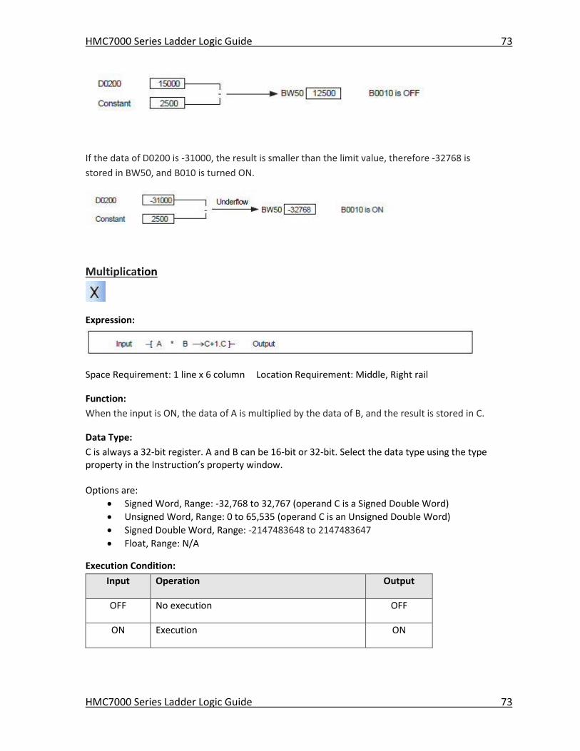
HMC7000 Series Ladder Logic Guide 73
HMC7000 Series Ladder Logic Guide 73
If the data of D0200 is -31000, the result is smaller than the limit value, therefore -32768 is
stored in BW50, and B010 is turned ON.
Multiplication
Expression:
Space Requirement: 1 line x 6 column Location Requirement: Middle, Right rail
Function:
When the input is ON, the data of A is multiplied by the data of B, and the result is stored in C.
Data Type:
C is always a 32-bit register. A and B can be 16-bit or 32-bit. Select the data type using the type property in the Instruction’s property window. Options are:
Signed Word, Range: -32,768 to 32,767 (operand C is a Signed Double Word)
Unsigned Word, Range: 0 to 65,535 (operand C is an Unsigned Double Word)
Signed Double Word, Range: -2147483648 to 2147483647
Float, Range: N/A
Execution Condition:
Input Operation Output
OFF No execution OFF
ON Execution ON
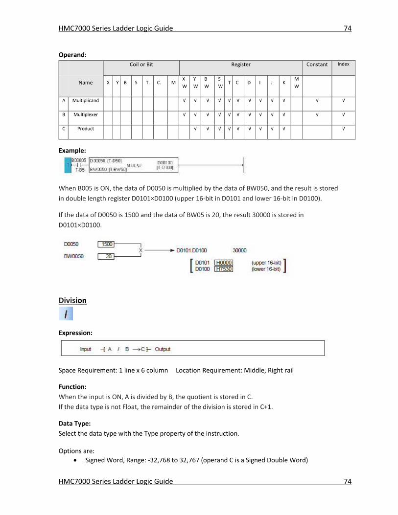
HMC7000 Series Ladder Logic Guide 74
HMC7000 Series Ladder Logic Guide 74
Operand:
Coil or Bit Register Constant Index
Name X Y B S T. C. M
X
W
Y
W
B
W
S
W T C D I J K
M
W
A Multiplicand √ √ √ √ √ √ √ √ √ √ √ √
B Multiplexer √ √ √ √ √ √ √ √ √ √ √ √
C Product √ √ √ √ √ √ √ √ √ √
Example:
When B005 is ON, the data of D0050 is multiplied by the data of BW050, and the result is stored
in double length register D0101×D0100 (upper 16-bit in D0101 and lower 16-bit in D0100).
If the data of D0050 is 1500 and the data of BW05 is 20, the result 30000 is stored in
D0101×D0100.
Division
Expression:
Space Requirement: 1 line x 6 column Location Requirement: Middle, Right rail
Function:
When the input is ON, A is divided by B, the quotient is stored in C.
If the data type is not Float, the remainder of the division is stored in C+1.
Data Type:
Select the data type with the Type property of the instruction. Options are:
Signed Word, Range: -32,768 to 32,767 (operand C is a Signed Double Word)
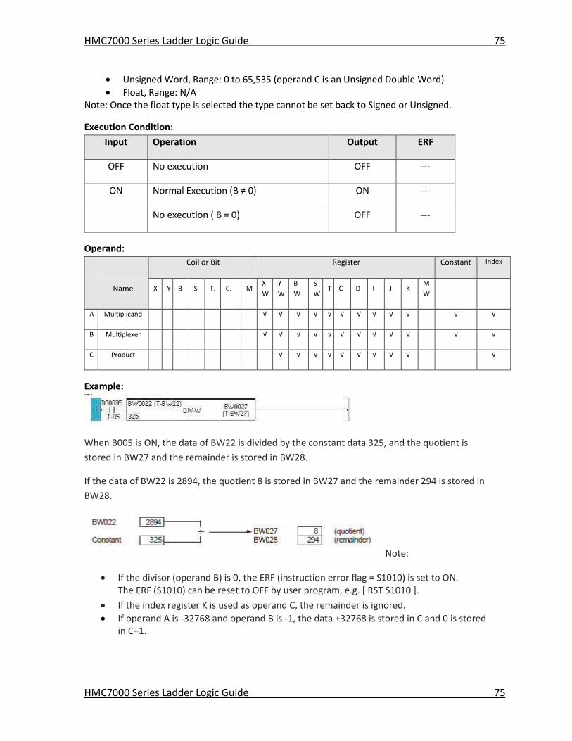
HMC7000 Series Ladder Logic Guide 75
HMC7000 Series Ladder Logic Guide 75
Unsigned Word, Range: 0 to 65,535 (operand C is an Unsigned Double Word)
Float, Range: N/A Note: Once the float type is selected the type cannot be set back to Signed or Unsigned.
Execution Condition:
Input Operation Output ERF
OFF No execution OFF ---
ON Normal Execution (B ≠ 0) ON ---
No execution ( B = 0) OFF ---
Operand:
Coil or Bit Register Constant Index
Name X Y B S T. C. M
X
W
Y
W
B
W
S
W T C D I J K
M
W
A Multiplicand √ √ √ √ √ √ √ √ √ √ √ √
B Multiplexer √ √ √ √ √ √ √ √ √ √ √ √
C Product √ √ √ √ √ √ √ √ √ √
Example:
When B005 is ON, the data of BW22 is divided by the constant data 325, and the quotient is
stored in BW27 and the remainder is stored in BW28.
If the data of BW22 is 2894, the quotient 8 is stored in BW27 and the remainder 294 is stored in
BW28.
Note:
If the divisor (operand B) is 0, the ERF (instruction error flag = S1010) is set to ON. The ERF (S1010) can be reset to OFF by user program, e.g. [ RST S1010 ].
If the index register K is used as operand C, the remainder is ignored.
If operand A is -32768 and operand B is -1, the data +32768 is stored in C and 0 is stored in C+1.
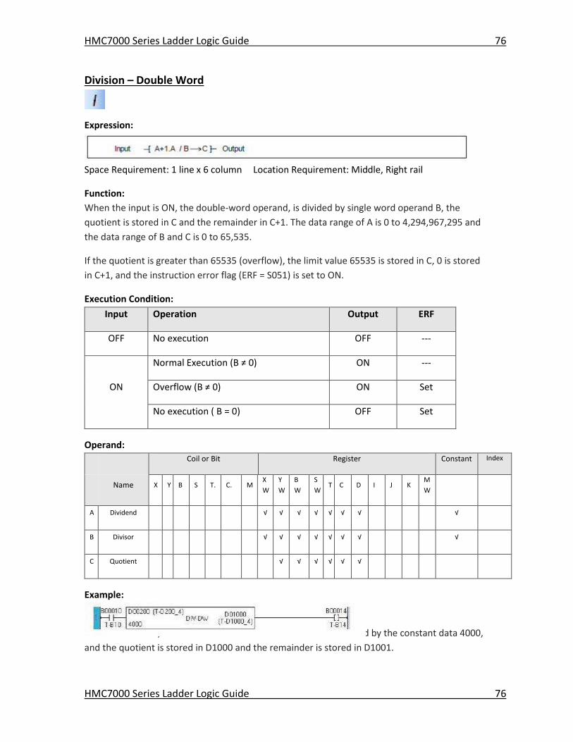
HMC7000 Series Ladder Logic Guide 76
HMC7000 Series Ladder Logic Guide 76
Division – Double Word
Expression:
Space Requirement: 1 line x 6 column Location Requirement: Middle, Right rail
Function:
When the input is ON, the double-word operand, is divided by single word operand B, the
quotient is stored in C and the remainder in C+1. The data range of A is 0 to 4,294,967,295 and
the data range of B and C is 0 to 65,535.
If the quotient is greater than 65535 (overflow), the limit value 65535 is stored in C, 0 is stored
in C+1, and the instruction error flag (ERF = S051) is set to ON.
Execution Condition:
Input Operation Output ERF
OFF No execution OFF ---
Normal Execution (B ≠ 0) ON ---
ON Overflow (B ≠ 0) ON Set
No execution ( B = 0) OFF Set
Operand:
Coil or Bit Register Constant Index
Name X Y B S T. C. M
X
W
Y
W
B
W
S
W T C D I J K
M
W
A Dividend √ √ √ √ √ √ √ √
B Divisor √ √ √ √ √ √ √ √
C Quotient √ √ √ √ √ √
Example:
When B010 is ON, the double-word data of D0201×D0200 is divided by the constant data 4000,
and the quotient is stored in D1000 and the remainder is stored in D1001.
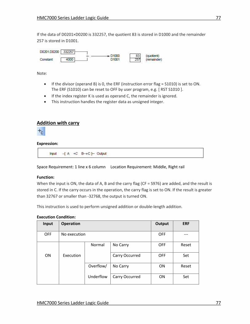
HMC7000 Series Ladder Logic Guide 77
HMC7000 Series Ladder Logic Guide 77
If the data of D0201×D0200 is 332257, the quotient 83 is stored in D1000 and the remainder
257 is stored in D1001.
Note:
If the divisor (operand B) is 0, the ERF (instruction error flag = S1010) is set to ON. The ERF (S1010) can be reset to OFF by user program, e.g. [ RST S1010 ].
If the index register K is used as operand C, the remainder is ignored.
This instruction handles the register data as unsigned integer.
Addition with carry
Expression:
Space Requirement: 1 line x 6 column Location Requirement: Middle, Right rail
Function:
When the input is ON, the data of A, B and the carry flag (CF = S976) are added, and the result is
stored in C. If the carry occurs in the operation, the carry flag is set to ON. If the result is greater
than 32767 or smaller than -32768, the output is turned ON.
This instruction is used to perform unsigned addition or double-length addition.
Execution Condition:
Input Operation Output ERF
OFF No execution OFF ---
Normal No Carry OFF Reset
ON Execution Carry Occurred OFF Set
Overflow/ No Carry ON Reset
Underflow Carry Occurred ON Set
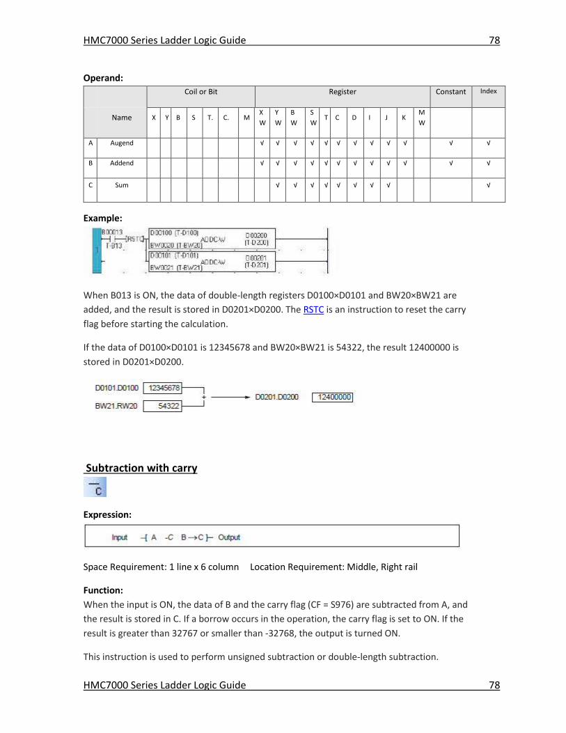
HMC7000 Series Ladder Logic Guide 78
HMC7000 Series Ladder Logic Guide 78
Operand:
Coil or Bit Register Constant Index
Name X Y B S T. C. M
X
W
Y
W
B
W
S
W T C D I J K
M
W
A Augend √ √ √ √ √ √ √ √ √ √ √ √
B Addend √ √ √ √ √ √ √ √ √ √ √ √
C Sum √ √ √ √ √ √ √ √ √
Example:
When B013 is ON, the data of double-length registers D0100×D0101 and BW20×BW21 are
added, and the result is stored in D0201×D0200. The RSTC is an instruction to reset the carry
flag before starting the calculation.
If the data of D0100×D0101 is 12345678 and BW20×BW21 is 54322, the result 12400000 is
stored in D0201×D0200.
Subtraction with carry
Expression:
Space Requirement: 1 line x 6 column Location Requirement: Middle, Right rail
Function:
When the input is ON, the data of B and the carry flag (CF = S976) are subtracted from A, and
the result is stored in C. If a borrow occurs in the operation, the carry flag is set to ON. If the
result is greater than 32767 or smaller than -32768, the output is turned ON.
This instruction is used to perform unsigned subtraction or double-length subtraction.
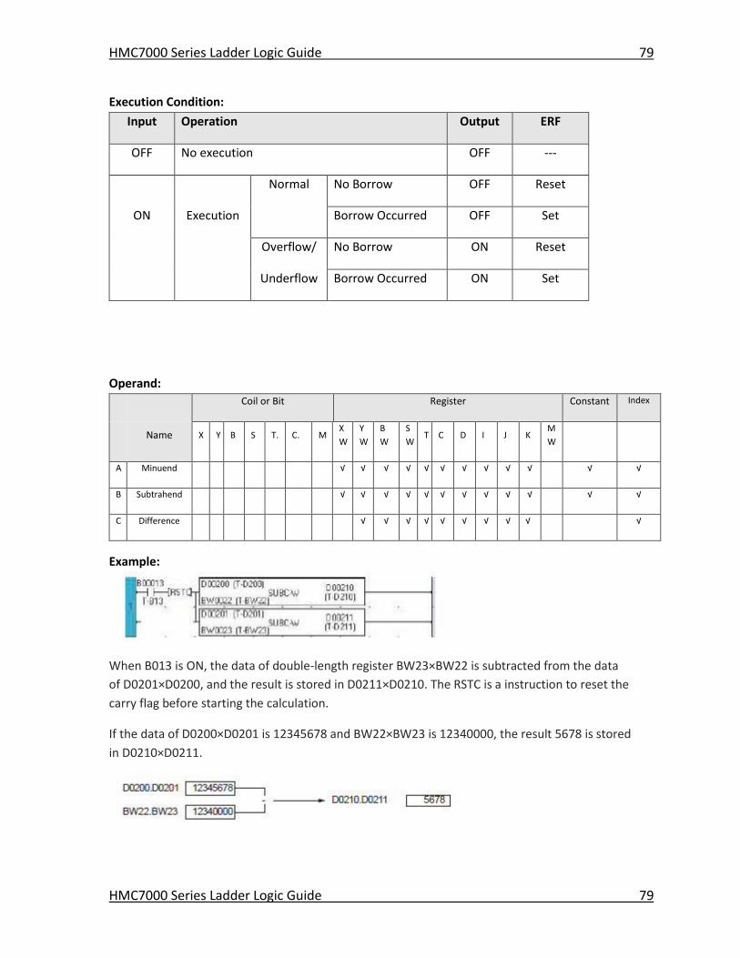
HMC7000 Series Ladder Logic Guide 79
HMC7000 Series Ladder Logic Guide 79
Execution Condition:
Input Operation Output ERF
OFF No execution OFF ---
Normal No Borrow OFF Reset
ON Execution Borrow Occurred OFF Set
Overflow/ No Borrow ON Reset
Underflow Borrow Occurred ON Set
Operand:
Coil or Bit Register Constant Index
Name X Y B S T. C. M
X
W
Y
W
B
W
S
W T C D I J K
M
W
A Minuend √ √ √ √ √ √ √ √ √ √ √ √
B Subtrahend √ √ √ √ √ √ √ √ √ √ √ √
C Difference √ √ √ √ √ √ √ √ √ √
Example:
When B013 is ON, the data of double-length register BW23×BW22 is subtracted from the data
of D0201×D0200, and the result is stored in D0211×D0210. The RSTC is a instruction to reset the
carry flag before starting the calculation.
If the data of D0200×D0201 is 12345678 and BW22×BW23 is 12340000, the result 5678 is stored
in D0210×D0211.
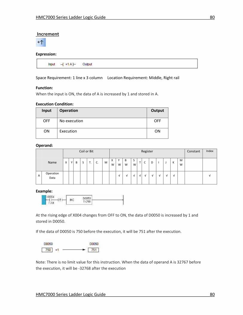
HMC7000 Series Ladder Logic Guide 80
HMC7000 Series Ladder Logic Guide 80
Increment
Expression:
Space Requirement: 1 line x 3 column Location Requirement: Middle, Right rail
Function:
When the input is ON, the data of A is increased by 1 and stored in A.
Execution Condition:
Input Operation Output
OFF No execution OFF
ON Execution ON
Operand:
Coil or Bit Register Constant Index
Name X Y B S T. C. M
X
W
Y
W
B
W
S
W T C D I J K
M
W
A Operation
Data √ √ √ √ √ √ √ √ √ √
Example:
At the rising edge of X004 changes from OFF to ON, the data of D0050 is increased by 1 and
stored in D0050.
If the data of D0050 is 750 before the execution, it will be 751 after the execution.
Note: There is no limit value for this instruction. When the data of operand A is 32767 before
the execution, it will be -32768 after the execution
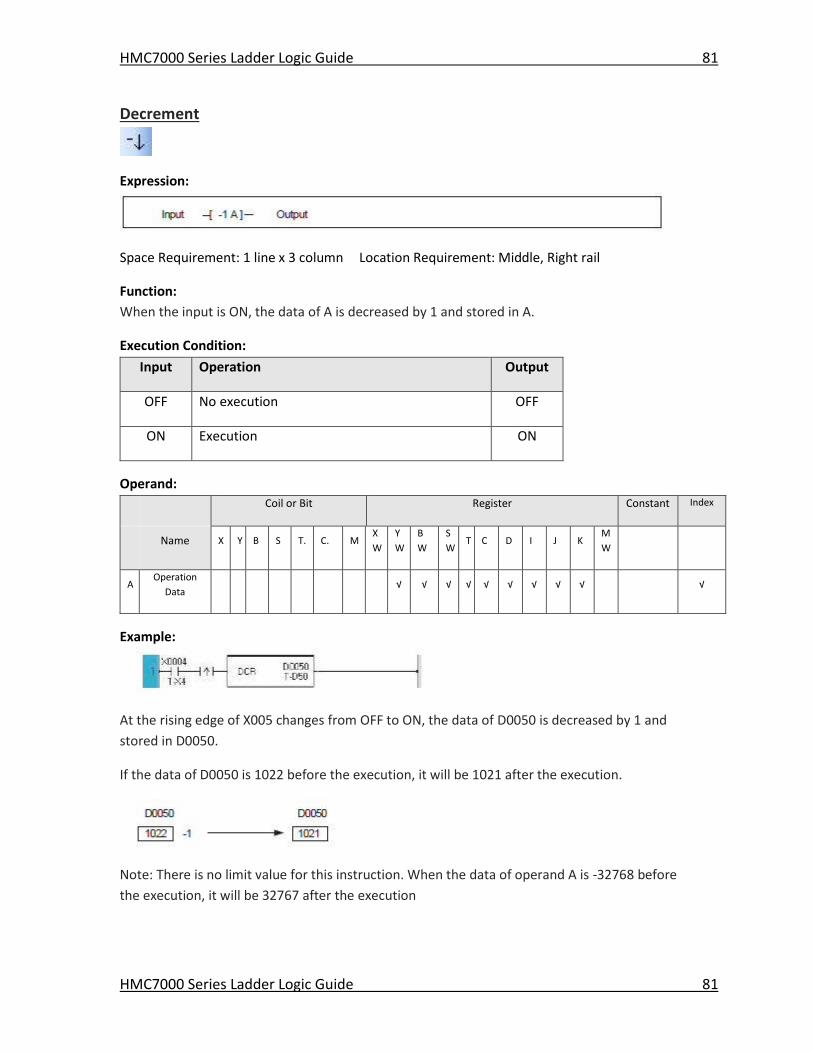
HMC7000 Series Ladder Logic Guide 81
HMC7000 Series Ladder Logic Guide 81
Decrement
Expression:
Space Requirement: 1 line x 3 column Location Requirement: Middle, Right rail
Function:
When the input is ON, the data of A is decreased by 1 and stored in A.
Execution Condition:
Input Operation Output
OFF No execution OFF
ON Execution ON
Operand:
Coil or Bit Register Constant Index
Name X Y B S T. C. M
X
W
Y
W
B
W
S
W T C D I J K
M
W
A Operation
Data √ √ √ √ √ √ √ √ √ √
Example:
At the rising edge of X005 changes from OFF to ON, the data of D0050 is decreased by 1 and
stored in D0050.
If the data of D0050 is 1022 before the execution, it will be 1021 after the execution.
Note: There is no limit value for this instruction. When the data of operand A is -32768 before
the execution, it will be 32767 after the execution
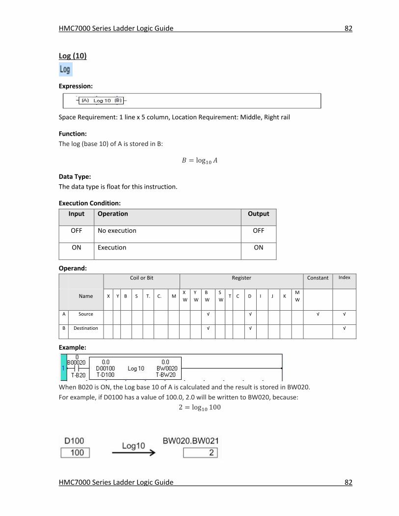
HMC7000 Series Ladder Logic Guide 82
HMC7000 Series Ladder Logic Guide 82
Log (10)
Expression:
Space Requirement: 1 line x 5 column, Location Requirement: Middle, Right rail
Function:
The log (base 10) of A is stored in B:
𝐵 = log10 𝐴
Data Type:
The data type is float for this instruction.
Execution Condition:
Input Operation Output
OFF No execution OFF
ON Execution ON
Operand:
Coil or Bit Register Constant Index
Name X Y B S T. C. M
X
W
Y
W
B
W
S
W T C D I J K
M
W
A Source √ √ √ √
B Destination √ √ √
Example:
When B020 is ON, the Log base 10 of A is calculated and the result is stored in BW020.
For example, if D0100 has a value of 100.0, 2.0 will be written to BW020, because:
2 = log10 100
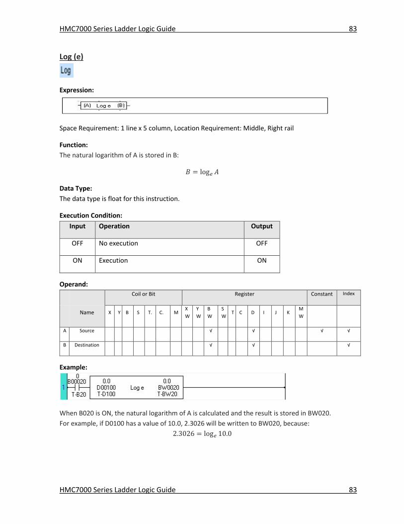
HMC7000 Series Ladder Logic Guide 83
HMC7000 Series Ladder Logic Guide 83
Log (e)
Expression:
Space Requirement: 1 line x 5 column, Location Requirement: Middle, Right rail
Function:
The natural logarithm of A is stored in B:
𝐵 = log𝑒 𝐴
Data Type:
The data type is float for this instruction.
Execution Condition:
Input Operation Output
OFF No execution OFF
ON Execution ON
Operand:
Coil or Bit Register Constant Index
Name X Y B S T. C. M
X
W
Y
W
B
W
S
W T C D I J K
M
W
A Source √ √ √ √
B Destination √ √ √
Example:
When B020 is ON, the natural logarithm of A is calculated and the result is stored in BW020.
For example, if D0100 has a value of 10.0, 2.3026 will be written to BW020, because:
2.3026 = log𝑒 10.0
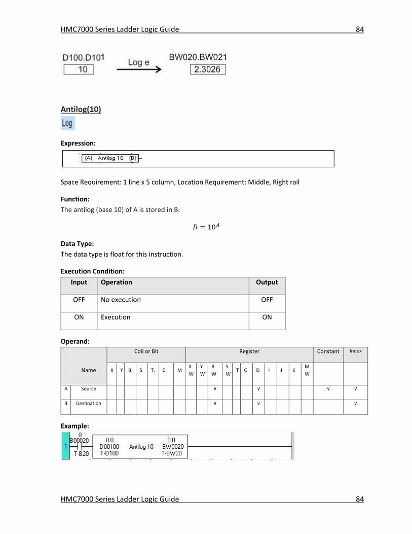
HMC7000 Series Ladder Logic Guide 84
HMC7000 Series Ladder Logic Guide 84
Antilog(10)
Expression:
Space Requirement: 1 line x 5 column, Location Requirement: Middle, Right rail
Function:
The antilog (base 10) of A is stored in B:
𝐵 = 10𝐴
Data Type:
The data type is float for this instruction.
Execution Condition:
Input Operation Output
OFF No execution OFF
ON Execution ON
Operand:
Coil or Bit Register Constant Index
Name X Y B S T. C. M
X
W
Y
W
B
W
S
W T C D I J K
M
W
A Source √ √ √ √
B Destination √ √ √
Example:
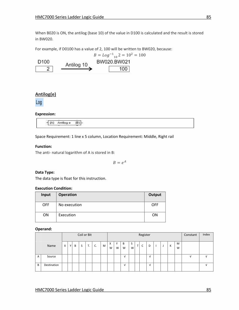
HMC7000 Series Ladder Logic Guide 85
HMC7000 Series Ladder Logic Guide 85
When B020 is ON, the antilog (base 10) of the value in D100 is calculated and the result is stored
in BW020.
For example, if D0100 has a value of 2, 100 will be written to BW020, because:
𝐵 = 𝐿𝑜𝑔−110 2 = 102 = 100
Antilog(e)
Expression:
Space Requirement: 1 line x 5 column, Location Requirement: Middle, Right rail
Function:
The anti- natural logarithm of A is stored in B:
𝐵 = 𝑒𝐴
Data Type:
The data type is float for this instruction.
Execution Condition:
Input Operation Output
OFF No execution OFF
ON Execution ON
Operand:
Coil or Bit Register Constant Index
Name X Y B S T. C. M
X
W
Y
W
B
W
S
W T C D I J K
M
W
A Source √ √ √ √
B Destination √ √ √
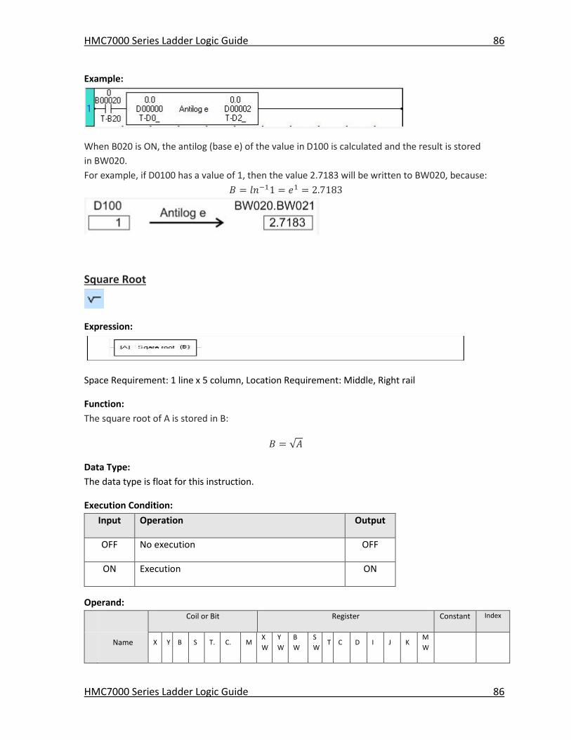
HMC7000 Series Ladder Logic Guide 86
HMC7000 Series Ladder Logic Guide 86
Example:
When B020 is ON, the antilog (base e) of the value in D100 is calculated and the result is stored
in BW020.
For example, if D0100 has a value of 1, then the value 2.7183 will be written to BW020, because:
𝐵 = 𝑙𝑛−11 = 𝑒1 = 2.7183
Square Root
Expression:
Space Requirement: 1 line x 5 column, Location Requirement: Middle, Right rail
Function:
The square root of A is stored in B:
𝐵 = √𝐴
Data Type:
The data type is float for this instruction.
Execution Condition:
Input Operation Output
OFF No execution OFF
ON Execution ON
Operand:
Coil or Bit Register Constant Index
Name X Y B S T. C. M
X
W
Y
W
B
W
S
W T C D I J K
M
W
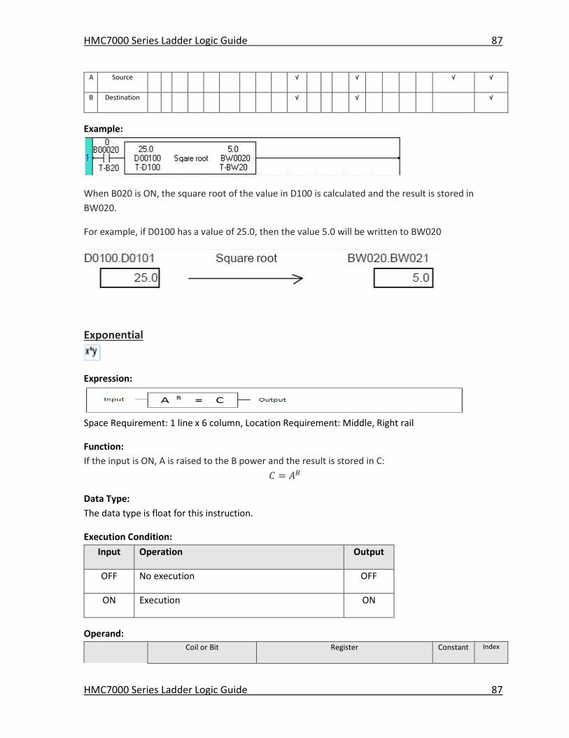
HMC7000 Series Ladder Logic Guide 87
HMC7000 Series Ladder Logic Guide 87
A Source √ √ √ √
B Destination √ √ √
Example:
When B020 is ON, the square root of the value in D100 is calculated and the result is stored in
BW020.
For example, if D0100 has a value of 25.0, then the value 5.0 will be written to BW020
Exponential
Expression:
Space Requirement: 1 line x 6 column, Location Requirement: Middle, Right rail
Function:
If the input is ON, A is raised to the B power and the result is stored in C:
𝐶 = 𝐴𝐵
Data Type:
The data type is float for this instruction.
Execution Condition:
Input Operation Output
OFF No execution OFF
ON Execution ON
Operand:
Coil or Bit Register Constant Index
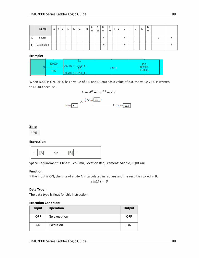
HMC7000 Series Ladder Logic Guide 88
HMC7000 Series Ladder Logic Guide 88
Name X Y B S T. C. M
X
W
Y
W
B
W
S
W T C D I J K
M
W
A Source √ √ √ √
B Destination √ √ √
Example:
When B020 is ON, D100 has a value of 5.0 and D0200 has a value of 2.0, the value 25.0 is written
to D0300 because
𝐶 = 𝐴𝐵 = 5.02.0 = 25.0
Sine
Expression:
Space Requirement: 1 line x 6 column, Location Requirement: Middle, Right rail
Function:
If the input is ON, the sine of angle A is calculated in radians and the result is stored in B:
sin(𝐴) = 𝐵
Data Type:
The data type is float for this instruction.
Execution Condition:
Input Operation Output
OFF No execution OFF
ON Execution ON
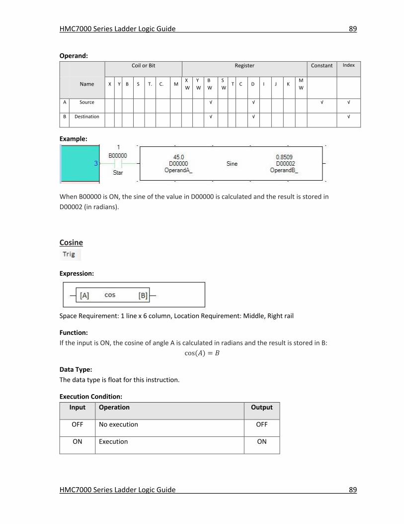
HMC7000 Series Ladder Logic Guide 89
HMC7000 Series Ladder Logic Guide 89
Operand:
Coil or Bit Register Constant Index
Name X Y B S T. C. M
X
W
Y
W
B
W
S
W T C D I J K
M
W
A Source √ √ √ √
B Destination √ √ √
Example:
When B00000 is ON, the sine of the value in D00000 is calculated and the result is stored in
D00002 (in radians).
Cosine
Expression:
Space Requirement: 1 line x 6 column, Location Requirement: Middle, Right rail
Function:
If the input is ON, the cosine of angle A is calculated in radians and the result is stored in B:
cos(𝐴) = 𝐵
Data Type:
The data type is float for this instruction.
Execution Condition:
Input Operation Output
OFF No execution OFF
ON Execution ON
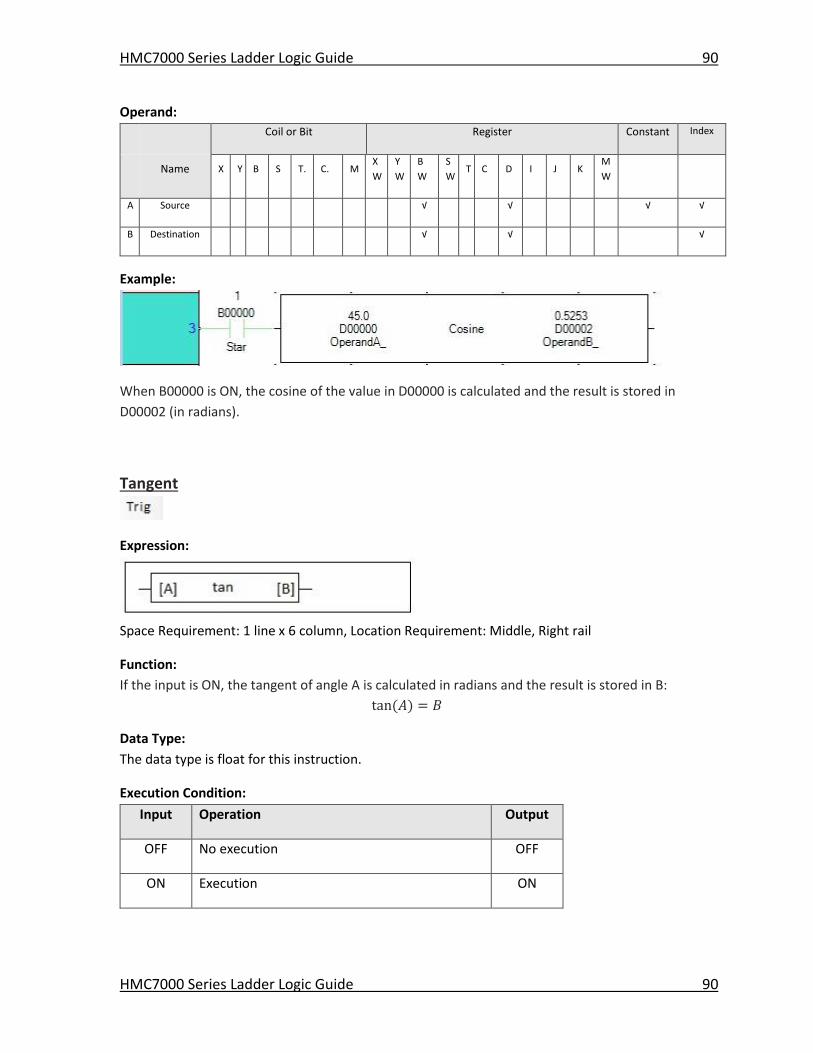
HMC7000 Series Ladder Logic Guide 90
HMC7000 Series Ladder Logic Guide 90
Operand:
Coil or Bit Register Constant Index
Name X Y B S T. C. M
X
W
Y
W
B
W
S
W T C D I J K
M
W
A Source √ √ √ √
B Destination √ √ √
Example:
When B00000 is ON, the cosine of the value in D00000 is calculated and the result is stored in
D00002 (in radians).
Tangent
Expression:
Space Requirement: 1 line x 6 column, Location Requirement: Middle, Right rail
Function:
If the input is ON, the tangent of angle A is calculated in radians and the result is stored in B:
tan(𝐴) = 𝐵
Data Type:
The data type is float for this instruction.
Execution Condition:
Input Operation Output
OFF No execution OFF
ON Execution ON
HMC7000 Series Ladder Logic Guide 91
HMC7000 Series Ladder Logic Guide 91
Operand:
Coil or Bit Register Constant Index
Name X Y B S T. C. M
X
W
Y
W
B
W
S
W T C D I J K
M
W
A Source √ √ √ √
B Destination √ √ √
Example:
When B00000 is ON, the tangent of the value in D00000 is calculated and the result is stored in
D00002 (in radians).
Compare Instructions
Greater Than
Expression:
Space Requirement: 1 line x 5 column Location Requirement: Middle, Right rail
Function:
If A is greater than B, and the input is ON, the output is turned ON.
Data Type:
Select the data type with the Data Properties menu in the Instruction Properties
The supported data types are:
Signed Word, Range: -32,768 to 32,767)
Unsigned Word, Range: 0 to 65,535
HMC7000 Series Ladder Logic Guide 92
HMC7000 Series Ladder Logic Guide 92
Signed Double Word, Range: -2,147,483,648 to 2,147,483,647
Float, Range: N/A
Execution Condition:
Input Operation Output
OFF No execution OFF
ON Execution A > B ON
A < B OFF
Operand:
Coil or Bit Register Constant Index
Name X Y B S T. C. M
X
W
Y
W
B
W
S
W T C D I J K
M
W
A Compared
Data √ √ √ √ √ √ √ √ √ √ √ √
B Reference
Data √ √ √ √ √ √ √ √ √ √ √ √
Example:
When B0005 is ON, the data of D0125 is compared with the constant data 2500, and if the data
of D0125 is greater than 2500, B0020 is turned ON.
If the data of D0125 is 3000, the comparison result is true. Consequently, B0020 is turned ON.
If the data of D0125 is -100, the comparison result is false. Consequently, B0005 is turned OFF
HMC7000 Series Ladder Logic Guide 93
HMC7000 Series Ladder Logic Guide 93
Greater Than or Equal
Expression:
Space Requirement: 1 line x 5 column Location Requirement: Middle, Right rail
Function:
If A is greater than or equal to B, and the input is ON, the output is turned ON.
Data Type:
Select the data type with the Data Properties menu in the Instruction Properties
The supported data types are:
Signed Word, Range: -32,768 to 32,767
Unsigned Word, Range: 0 to 65,535
Signed Double Word, Range: -2,147,483,648 to 2,147,483,647
Float, Range: N/A
Execution Condition:
Input Operation Output
OFF No execution OFF
ON Execution A > B ON
A < B OFF
Operand:
Coil or Bit Register Constant Index
Name X Y B S T. C. M
X
W
Y
W
B
W
S
W T C D I J K
M
W
A Compared
Data √ √ √ √ √ √ √ √ √ √ √ √
B Reference
Data √ √ √ √ √ √ √ √ √ √ √ √
HMC7000 Series Ladder Logic Guide 94
HMC7000 Series Ladder Logic Guide 94
Example:
When B0005 is ON, the data of D0125 is compared with the data of D0020, and if the data of
D0125 is greater than or equal to the data of D0020, B020 is turned ON.
If the data of D0125 is 3000 and that of D0020 is 3000, the comparison result is true.
Consequently, B020 is turned ON.
If the data of D0125 is -1500 and that of D0020 is 0, the comparison result is false.
Consequently, B020 is turned OFF.
Equal
Expression:
Space Requirement: 1 line x 5 column Location Requirement: Middle, Right rail
Function:
If A is equal to B, and the input is ON, the output is turned ON.
Data Type:
Select the data type with the Data Properties menu in the Instruction Properties
The supported data types are:
Signed Word, Range: -32,768 to 32,767
Unsigned Word, Range: 0 to 65,535
Signed Double Word, Range: -2,147,483,648 to 2,147,483,647
Float, Range: N/A
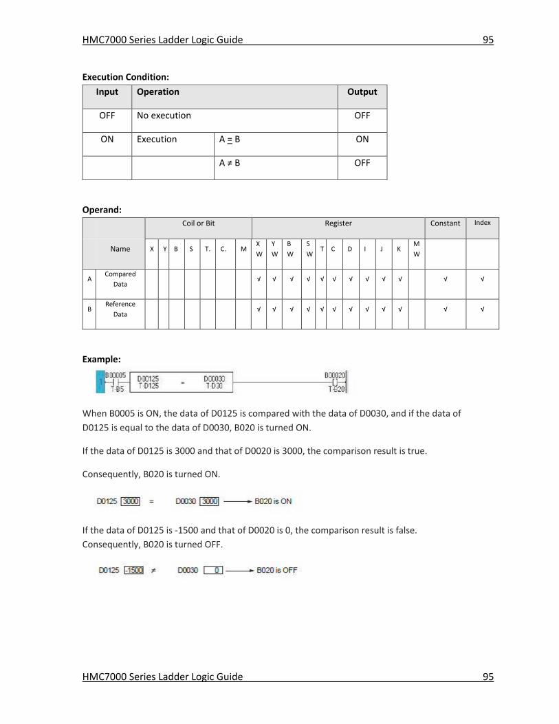
HMC7000 Series Ladder Logic Guide 95
HMC7000 Series Ladder Logic Guide 95
Execution Condition:
Input Operation Output
OFF No execution OFF
ON Execution A = B ON
A ≠ B OFF
Operand:
Coil or Bit Register Constant Index
Name X Y B S T. C. M
X
W
Y
W
B
W
S
W T C D I J K
M
W
A Compared
Data √ √ √ √ √ √ √ √ √ √ √ √
B Reference
Data √ √ √ √ √ √ √ √ √ √ √ √
Example:
When B0005 is ON, the data of D0125 is compared with the data of D0030, and if the data of
D0125 is equal to the data of D0030, B020 is turned ON.
If the data of D0125 is 3000 and that of D0020 is 3000, the comparison result is true.
Consequently, B020 is turned ON.
If the data of D0125 is -1500 and that of D0020 is 0, the comparison result is false.
Consequently, B020 is turned OFF.
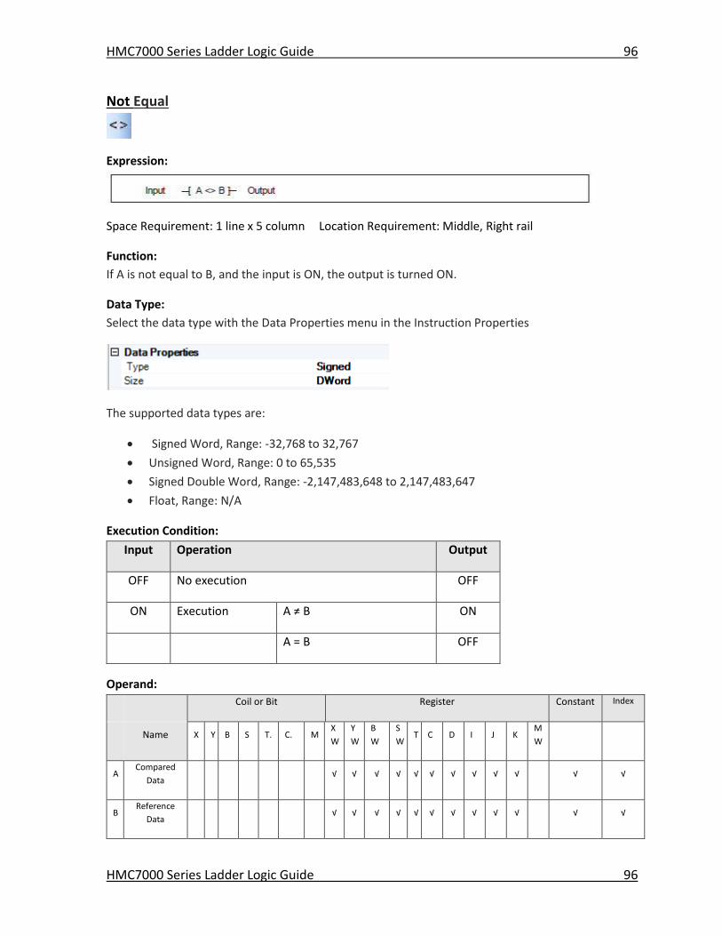
HMC7000 Series Ladder Logic Guide 96
HMC7000 Series Ladder Logic Guide 96
Not Equal
Expression:
Space Requirement: 1 line x 5 column Location Requirement: Middle, Right rail
Function:
If A is not equal to B, and the input is ON, the output is turned ON.
Data Type:
Select the data type with the Data Properties menu in the Instruction Properties
The supported data types are:
Signed Word, Range: -32,768 to 32,767
Unsigned Word, Range: 0 to 65,535
Signed Double Word, Range: -2,147,483,648 to 2,147,483,647
Float, Range: N/A
Execution Condition:
Input Operation Output
OFF No execution OFF
ON Execution A ≠ B ON
A = B OFF
Operand:
Coil or Bit Register Constant Index
Name X Y B S T. C. M
X
W
Y
W
B
W
S
W T C D I J K
M
W
A Compared
Data √ √ √ √ √ √ √ √ √ √ √ √
B Reference
Data √ √ √ √ √ √ √ √ √ √ √ √
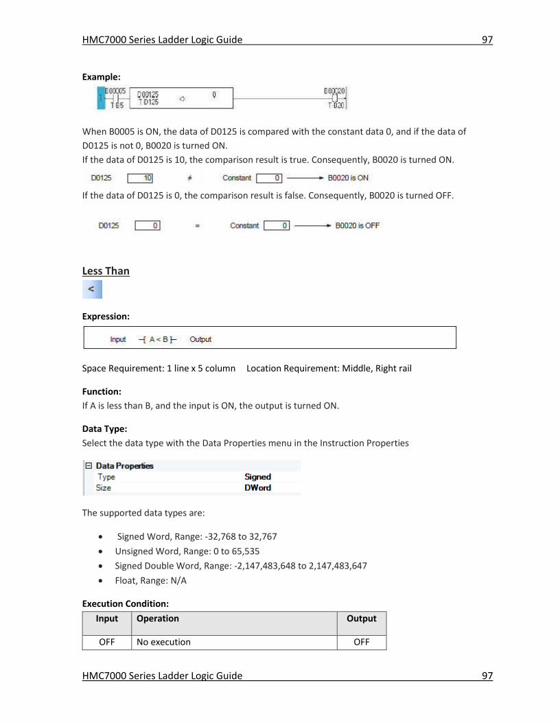
HMC7000 Series Ladder Logic Guide 97
HMC7000 Series Ladder Logic Guide 97
Example:
When B0005 is ON, the data of D0125 is compared with the constant data 0, and if the data of
D0125 is not 0, B0020 is turned ON.
If the data of D0125 is 10, the comparison result is true. Consequently, B0020 is turned ON.
If the data of D0125 is 0, the comparison result is false. Consequently, B0020 is turned OFF.
Less Than
Expression:
Space Requirement: 1 line x 5 column Location Requirement: Middle, Right rail
Function:
If A is less than B, and the input is ON, the output is turned ON.
Data Type:
Select the data type with the Data Properties menu in the Instruction Properties
The supported data types are:
Signed Word, Range: -32,768 to 32,767
Unsigned Word, Range: 0 to 65,535
Signed Double Word, Range: -2,147,483,648 to 2,147,483,647
Float, Range: N/A
Execution Condition:
Input Operation Output
OFF No execution OFF
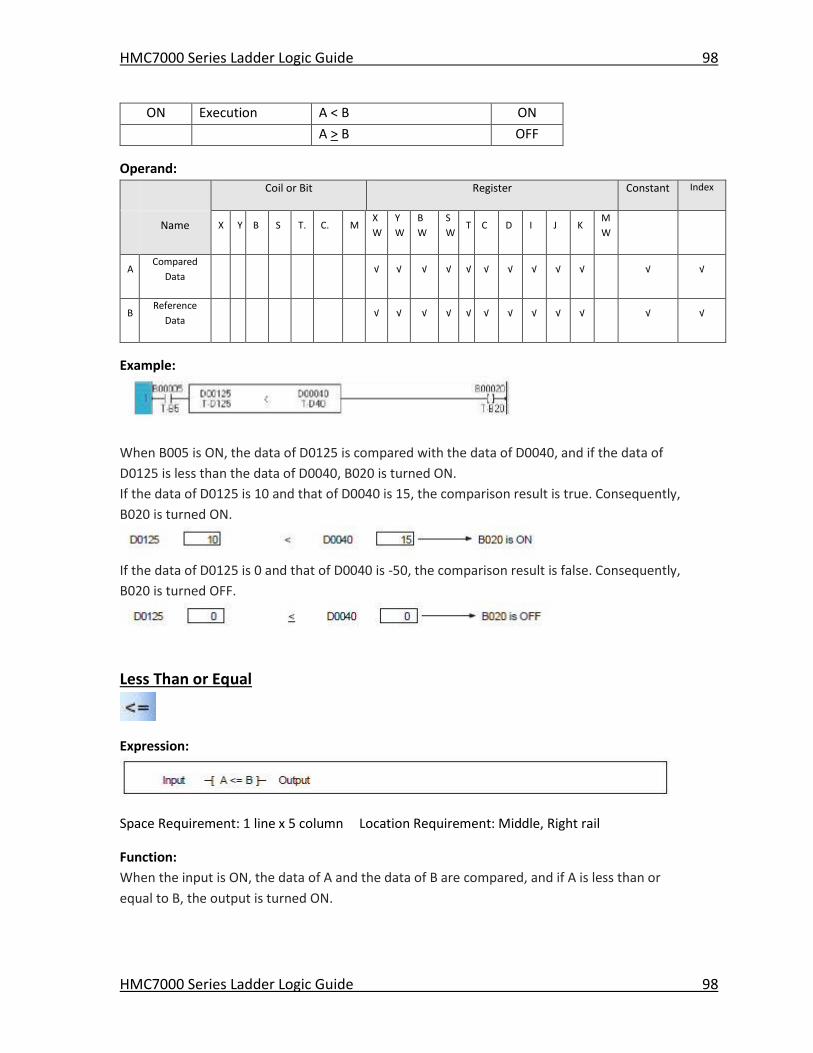
HMC7000 Series Ladder Logic Guide 98
HMC7000 Series Ladder Logic Guide 98
ON Execution A < B ON
A > B OFF
Operand:
Coil or Bit Register Constant Index
Name X Y B S T. C. M
X
W
Y
W
B
W
S
W T C D I J K
M
W
A Compared
Data √ √ √ √ √ √ √ √ √ √ √ √
B Reference
Data √ √ √ √ √ √ √ √ √ √ √ √
Example:
When B005 is ON, the data of D0125 is compared with the data of D0040, and if the data of
D0125 is less than the data of D0040, B020 is turned ON.
If the data of D0125 is 10 and that of D0040 is 15, the comparison result is true. Consequently,
B020 is turned ON.
If the data of D0125 is 0 and that of D0040 is -50, the comparison result is false. Consequently,
B020 is turned OFF.
Less Than or Equal
Expression:
Space Requirement: 1 line x 5 column Location Requirement: Middle, Right rail
Function:
When the input is ON, the data of A and the data of B are compared, and if A is less than or
equal to B, the output is turned ON.
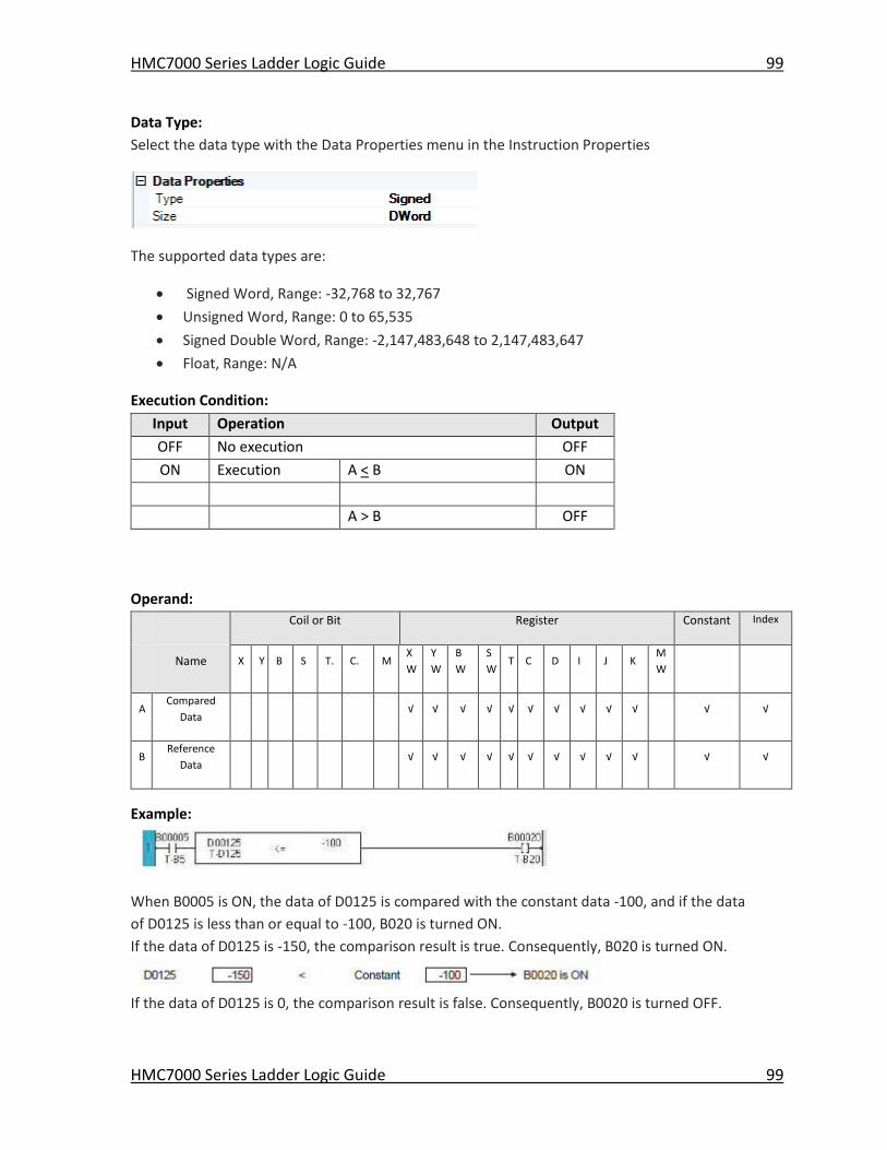
HMC7000 Series Ladder Logic Guide 99
HMC7000 Series Ladder Logic Guide 99
Data Type:
Select the data type with the Data Properties menu in the Instruction Properties
The supported data types are:
Signed Word, Range: -32,768 to 32,767
Unsigned Word, Range: 0 to 65,535
Signed Double Word, Range: -2,147,483,648 to 2,147,483,647
Float, Range: N/A
Execution Condition:
Input Operation Output
OFF No execution OFF
ON Execution A < B ON
A > B OFF
Operand:
Coil or Bit Register Constant Index
Name X Y B S T. C. M
X
W
Y
W
B
W
S
W T C D I J K
M
W
A Compared
Data √ √ √ √ √ √ √ √ √ √ √ √
B Reference
Data √ √ √ √ √ √ √ √ √ √ √ √
Example:
When B0005 is ON, the data of D0125 is compared with the constant data -100, and if the data
of D0125 is less than or equal to -100, B020 is turned ON.
If the data of D0125 is -150, the comparison result is true. Consequently, B020 is turned ON.
If the data of D0125 is 0, the comparison result is false. Consequently, B0020 is turned OFF.
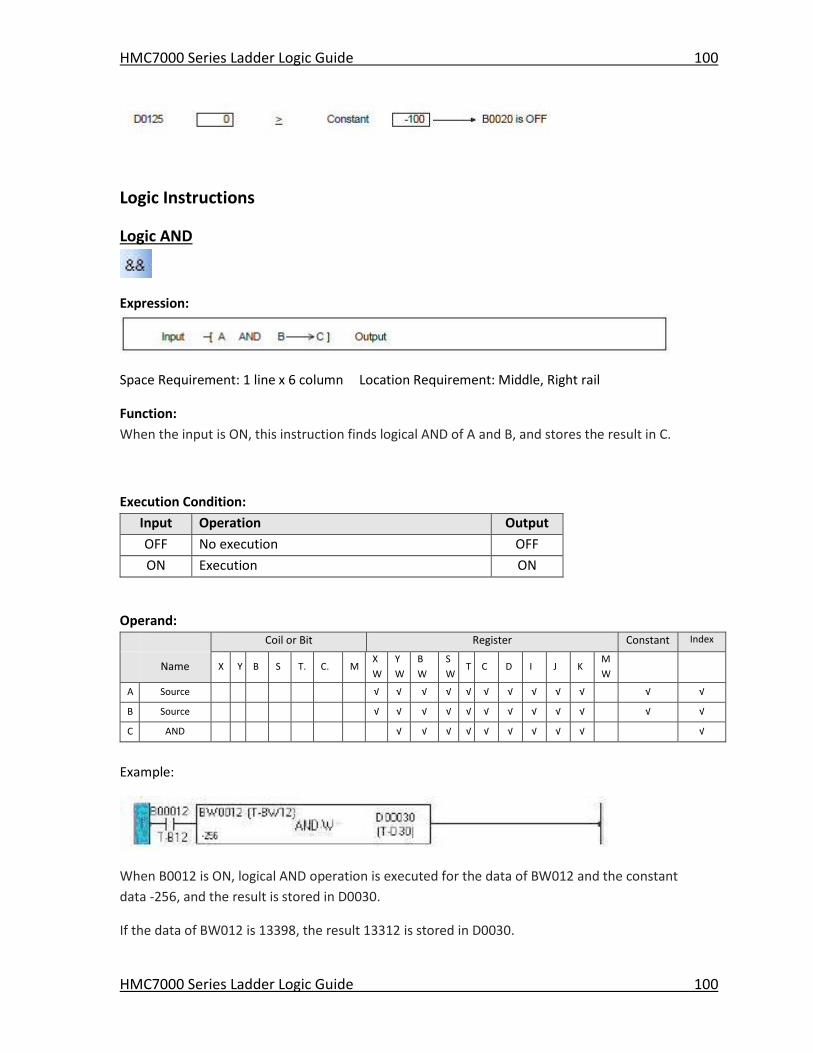
HMC7000 Series Ladder Logic Guide 100
HMC7000 Series Ladder Logic Guide 100
Logic Instructions
Logic AND
Expression:
Space Requirement: 1 line x 6 column Location Requirement: Middle, Right rail
Function:
When the input is ON, this instruction finds logical AND of A and B, and stores the result in C.
Execution Condition:
Input Operation Output
OFF No execution OFF
ON Execution ON
Operand:
Coil or Bit Register Constant Index
Name X Y B S T. C. M
X
W
Y
W
B
W
S
W T C D I J K
M
W
A Source √ √ √ √ √ √ √ √ √ √ √ √
B Source √ √ √ √ √ √ √ √ √ √ √ √
C AND √ √ √ √ √ √ √ √ √ √
Example:
When B0012 is ON, logical AND operation is executed for the data of BW012 and the constant
data -256, and the result is stored in D0030.
If the data of BW012 is 13398, the result 13312 is stored in D0030.
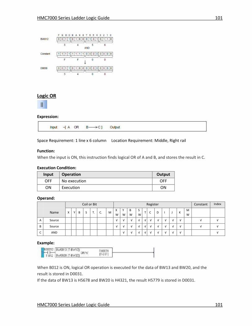
HMC7000 Series Ladder Logic Guide 101
HMC7000 Series Ladder Logic Guide 101
Logic OR
Expression:
Space Requirement: 1 line x 6 column Location Requirement: Middle, Right rail
Function:
When the input is ON, this instruction finds logical OR of A and B, and stores the result in C.
Execution Condition:
Input Operation Output
OFF No execution OFF
ON Execution ON
Operand:
Coil or Bit Register Constant Index
Name X Y B S T. C. M
X
W
Y
W
B
W
S
W T C D I J K
M
W
A Source √ √ √ √ √ √ √ √ √ √ √ √
B Source √ √ √ √ √ √ √ √ √ √ √ √
C AND √ √ √ √ √ √ √ √ √ √
Example:
When B012 is ON, logical OR operation is executed for the data of BW13 and BW20, and the
result is stored in D0031.
If the data of BW13 is H5678 and BW20 is H4321, the result H5779 is stored in D0031.
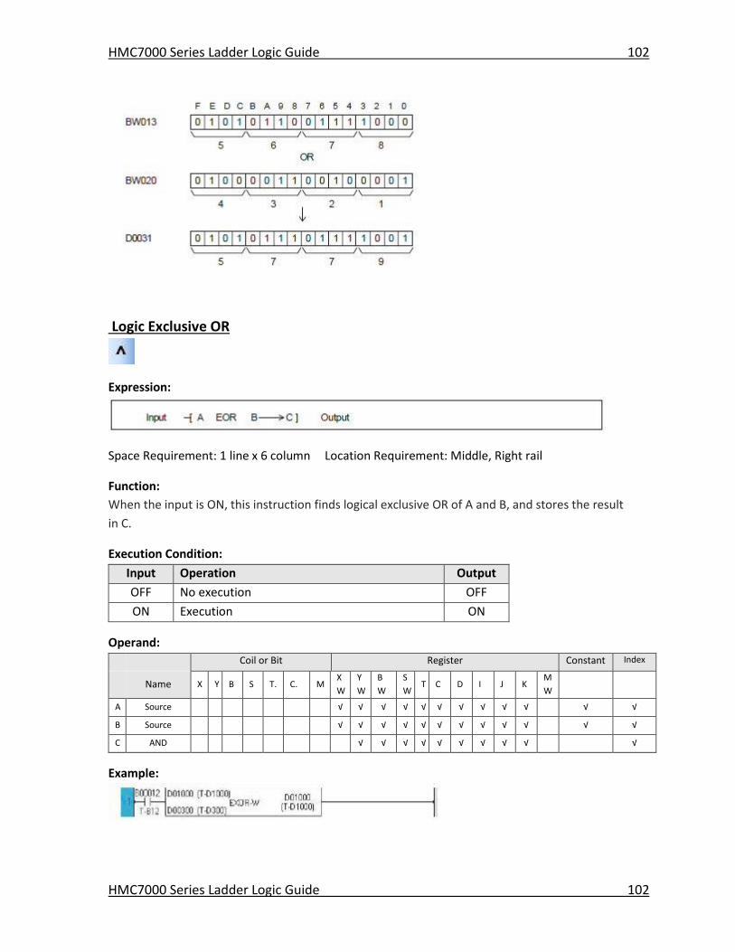
HMC7000 Series Ladder Logic Guide 102
HMC7000 Series Ladder Logic Guide 102
Logic Exclusive OR
Expression:
Space Requirement: 1 line x 6 column Location Requirement: Middle, Right rail
Function:
When the input is ON, this instruction finds logical exclusive OR of A and B, and stores the result
in C.
Execution Condition:
Input Operation Output
OFF No execution OFF
ON Execution ON
Operand:
Coil or Bit Register Constant Index
Name X Y B S T. C. M
X
W
Y
W
B
W
S
W T C D I J K
M
W
A Source √ √ √ √ √ √ √ √ √ √ √ √
B Source √ √ √ √ √ √ √ √ √ √ √ √
C AND √ √ √ √ √ √ √ √ √ √
Example:
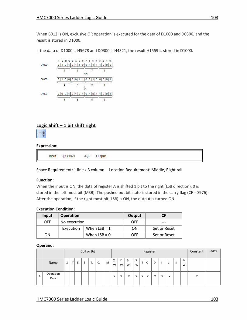
HMC7000 Series Ladder Logic Guide 103
HMC7000 Series Ladder Logic Guide 103
When B012 is ON, exclusive OR operation is executed for the data of D1000 and D0300, and the
result is stored in D1000.
If the data of D1000 is H5678 and D0300 is H4321, the result H1559 is stored in D1000.
Logic Shift – 1 bit shift right
Expression:
Space Requirement: 1 line x 3 column Location Requirement: Middle, Right rail
Function:
When the input is ON, the data of register A is shifted 1 bit to the right (LSB direction). 0 is
stored in the left most bit (MSB). The pushed out bit state is stored in the carry flag (CF = S976).
After the operation, if the right most bit (LSB) is ON, the output is turned ON.
Execution Condition:
Input Operation Output CF
OFF No execution OFF ---
Execution When LSB = 1 ON Set or Reset
ON When LSB = 0 OFF Set or Reset
Operand:
Coil or Bit Register Constant Index
Name X Y B S T. C. M
X
W
Y
W
B
W
S
W T C D I J K
M
W
A Operation
Data √ √ √ √ √ √ √ √ √ √
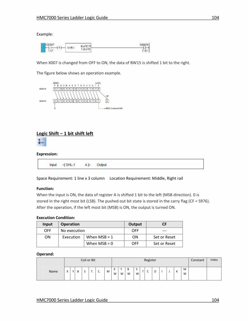
HMC7000 Series Ladder Logic Guide 104
HMC7000 Series Ladder Logic Guide 104
Example:
When X007 is changed from OFF to ON, the data of BW15 is shifted 1 bit to the right.
The figure below shows an operation example.
Logic Shift – 1 bit shift left
Expression:
Space Requirement: 1 line x 3 column Location Requirement: Middle, Right rail
Function:
When the input is ON, the data of register A is shifted 1 bit to the left (MSB direction). 0 is
stored in the right most bit (LSB). The pushed out bit state is stored in the carry flag (CF = S976).
After the operation, if the left most bit (MSB) is ON, the output is turned ON.
Execution Condition:
Input Operation Output CF
OFF No execution OFF ---
ON Execution When MSB = 1 ON Set or Reset
When MSB = 0 OFF Set or Reset
Operand:
Coil or Bit Register Constant Index
Name X Y B S T. C. M
X
W
Y
W
B
W
S
W T C D I J K
M
W
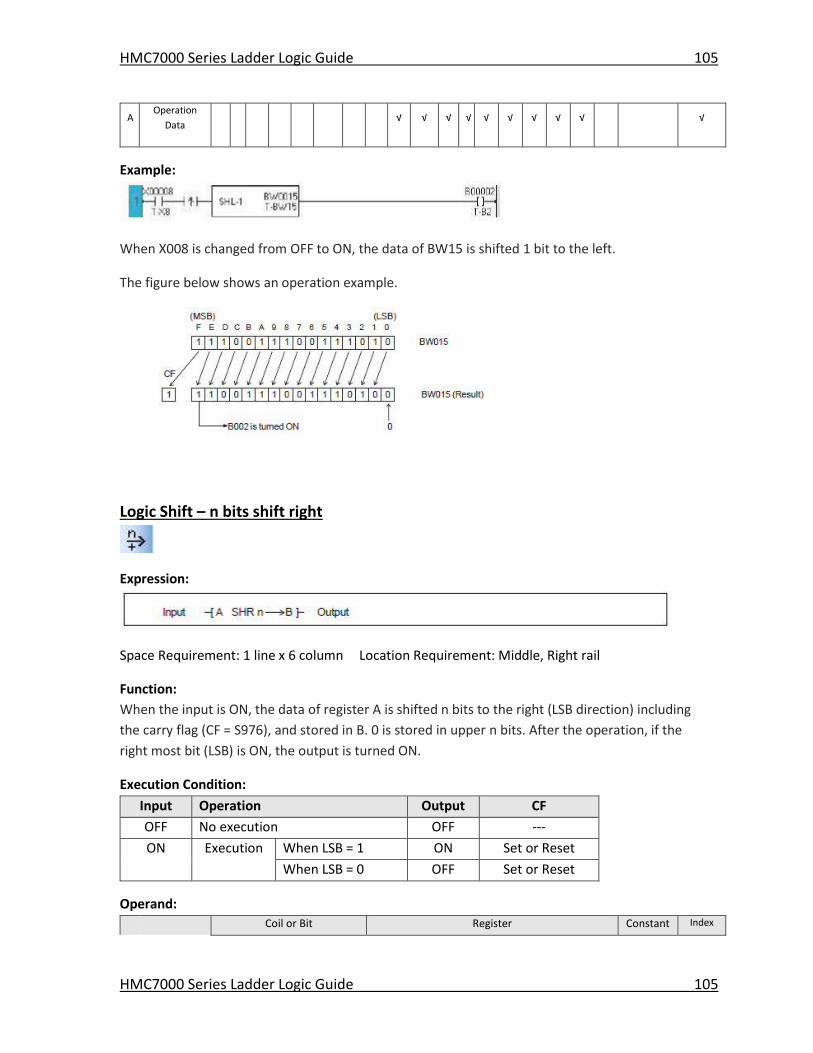
HMC7000 Series Ladder Logic Guide 105
HMC7000 Series Ladder Logic Guide 105
A Operation
Data √ √ √ √ √ √ √ √ √ √
Example:
When X008 is changed from OFF to ON, the data of BW15 is shifted 1 bit to the left.
The figure below shows an operation example.
Logic Shift – n bits shift right
Expression:
Space Requirement: 1 line x 6 column Location Requirement: Middle, Right rail
Function:
When the input is ON, the data of register A is shifted n bits to the right (LSB direction) including
the carry flag (CF = S976), and stored in B. 0 is stored in upper n bits. After the operation, if the
right most bit (LSB) is ON, the output is turned ON.
Execution Condition:
Input Operation Output CF
OFF No execution OFF ---
ON Execution When LSB = 1 ON Set or Reset
When LSB = 0 OFF Set or Reset
Operand:
Coil or Bit Register Constant Index
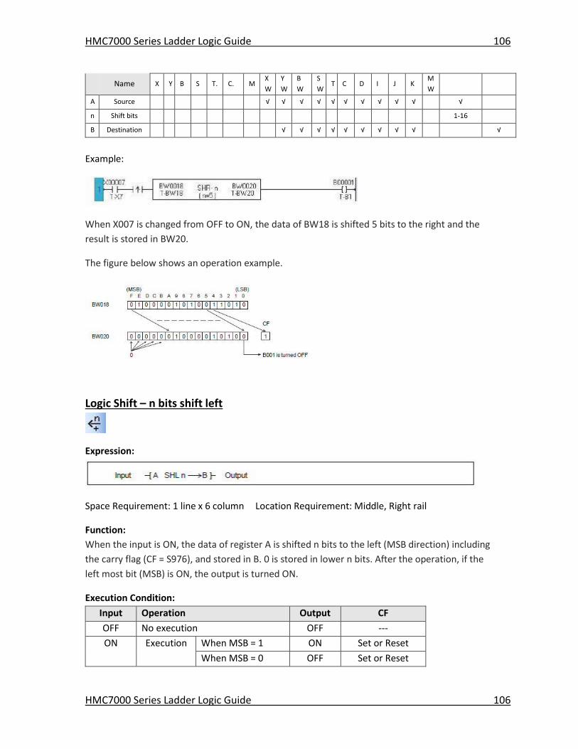
HMC7000 Series Ladder Logic Guide 106
HMC7000 Series Ladder Logic Guide 106
Name X Y B S T. C. M
X
W
Y
W
B
W
S
W T C D I J K
M
W
A Source √ √ √ √ √ √ √ √ √ √ √
n Shift bits 1-16
B Destination √ √ √ √ √ √ √ √ √ √
Example:
When X007 is changed from OFF to ON, the data of BW18 is shifted 5 bits to the right and the
result is stored in BW20.
The figure below shows an operation example.
Logic Shift – n bits shift left
Expression:
Space Requirement: 1 line x 6 column Location Requirement: Middle, Right rail
Function:
When the input is ON, the data of register A is shifted n bits to the left (MSB direction) including
the carry flag (CF = S976), and stored in B. 0 is stored in lower n bits. After the operation, if the
left most bit (MSB) is ON, the output is turned ON.
Execution Condition:
Input Operation Output CF
OFF No execution OFF ---
ON Execution When MSB = 1 ON Set or Reset
When MSB = 0 OFF Set or Reset
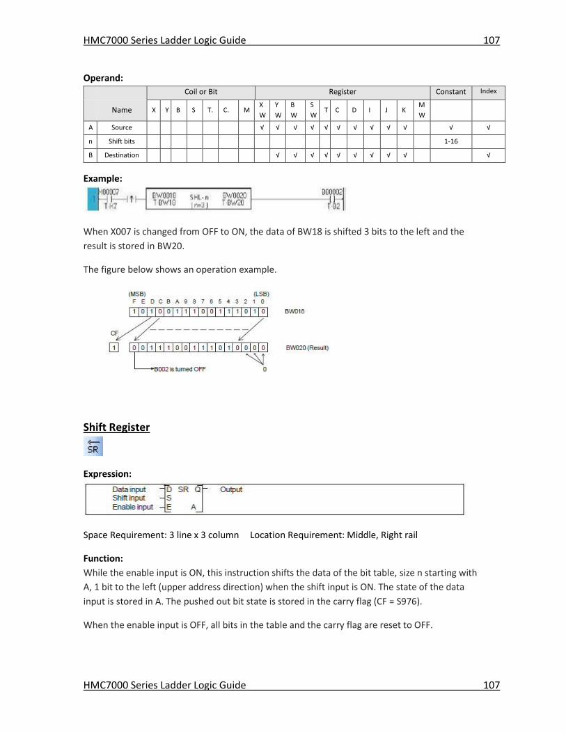
HMC7000 Series Ladder Logic Guide 107
HMC7000 Series Ladder Logic Guide 107
Operand:
Coil or Bit Register Constant Index
Name X Y B S T. C. M
X
W
Y
W
B
W
S
W T C D I J K
M
W
A Source √ √ √ √ √ √ √ √ √ √ √ √
n Shift bits 1-16
B Destination √ √ √ √ √ √ √ √ √ √
Example:
When X007 is changed from OFF to ON, the data of BW18 is shifted 3 bits to the left and the
result is stored in BW20.
The figure below shows an operation example.
Shift Register
Expression:
Space Requirement: 3 line x 3 column Location Requirement: Middle, Right rail
Function:
While the enable input is ON, this instruction shifts the data of the bit table, size n starting with
A, 1 bit to the left (upper address direction) when the shift input is ON. The state of the data
input is stored in A. The pushed out bit state is stored in the carry flag (CF = S976).
When the enable input is OFF, all bits in the table and the carry flag are reset to OFF.
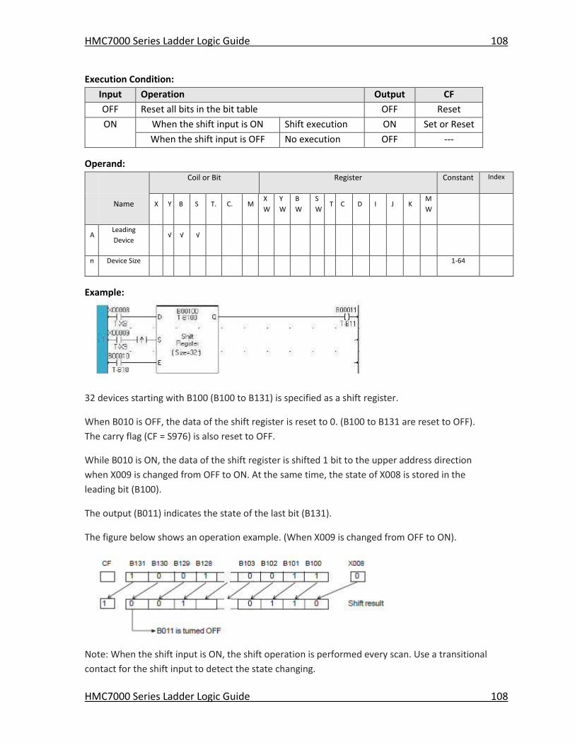
HMC7000 Series Ladder Logic Guide 108
HMC7000 Series Ladder Logic Guide 108
Execution Condition:
Input Operation Output CF
OFF Reset all bits in the bit table OFF Reset
ON When the shift input is ON Shift execution ON Set or Reset
When the shift input is OFF No execution OFF ---
Operand:
Coil or Bit Register Constant Index
Name X Y B S T. C. M
X
W
Y
W
B
W
S
W T C D I J K
M
W
A Leading
Device √ √ √
n Device Size 1-64
Example:
32 devices starting with B100 (B100 to B131) is specified as a shift register.
When B010 is OFF, the data of the shift register is reset to 0. (B100 to B131 are reset to OFF).
The carry flag (CF = S976) is also reset to OFF.
While B010 is ON, the data of the shift register is shifted 1 bit to the upper address direction
when X009 is changed from OFF to ON. At the same time, the state of X008 is stored in the
leading bit (B100).
The output (B011) indicates the state of the last bit (B131).
The figure below shows an operation example. (When X009 is changed from OFF to ON).
Note: When the shift input is ON, the shift operation is performed every scan. Use a transitional
contact for the shift input to detect the state changing.
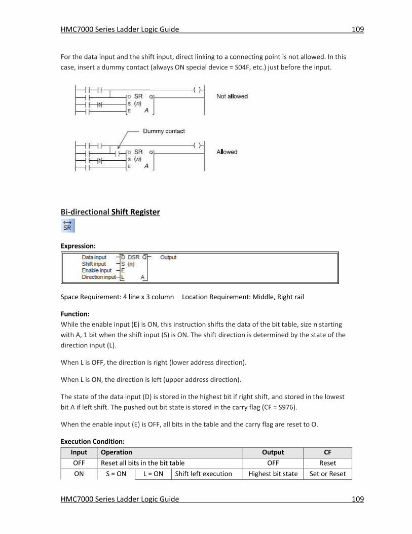
HMC7000 Series Ladder Logic Guide 109
HMC7000 Series Ladder Logic Guide 109
For the data input and the shift input, direct linking to a connecting point is not allowed. In this
case, insert a dummy contact (always ON special device = S04F, etc.) just before the input.
Bi-directional Shift Register
Expression:
Space Requirement: 4 line x 3 column Location Requirement: Middle, Right rail
Function:
While the enable input (E) is ON, this instruction shifts the data of the bit table, size n starting
with A, 1 bit when the shift input (S) is ON. The shift direction is determined by the state of the
direction input (L).
When L is OFF, the direction is right (lower address direction).
When L is ON, the direction is left (upper address direction).
The state of the data input (D) is stored in the highest bit if right shift, and stored in the lowest
bit A if left shift. The pushed out bit state is stored in the carry flag (CF = S976).
When the enable input (E) is OFF, all bits in the table and the carry flag are reset to O.
Execution Condition:
Input Operation Output CF
OFF Reset all bits in the bit table OFF Reset
ON S = ON L = ON Shift left execution Highest bit state Set or Reset
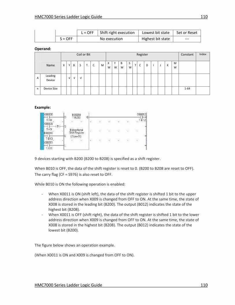
HMC7000 Series Ladder Logic Guide 110
HMC7000 Series Ladder Logic Guide 110
L = OFF Shift right execution Lowest bit state Set or Reset
S = OFF No execution Highest bit state ---
Operand:
Coil or Bit Register Constant Index
Name X Y B S T. C. M
X
W
Y
W
B
W
S
W T C D I J K
M
W
A Leading
Device √ √ √
n Device Size 1-64
Example:
9 devices starting with B200 (B200 to B208) is specified as a shift register.
When B010 is OFF, the data of the shift register is reset to 0. (B200 to B208 are reset to OFF).
The carry flag (CF = S976) is also reset to OFF.
While B010 is ON the following operation is enabled:
- When X0011 is ON (shift left), the data of the shift register is shifted 1 bit to the upper address direction when X009 is changed from OFF to ON. At the same time, the state of X008 is stored in the leading bit (B200). The output (B012) indicates the state of the highest bit (B208).
- When X0011 is OFF (shift right), the data of the shift register is shifted 1 bit to the lower address direction when X009 is changed from OFF to ON. At the same time, the state of X008 is stored in the highest bit (B208). The output (B012) indicates the state of the lowest bit (B200).
The figure below shows an operation example.
(When X0011 is ON and X009 is changed from OFF to ON).
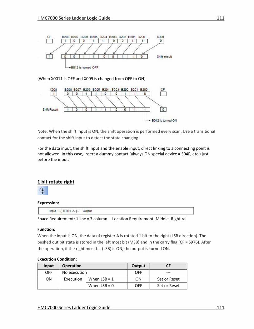
HMC7000 Series Ladder Logic Guide 111
HMC7000 Series Ladder Logic Guide 111
(When X0011 is OFF and X009 is changed from OFF to ON)
Note: When the shift input is ON, the shift operation is performed every scan. Use a transitional
contact for the shift input to detect the state changing.
For the data input, the shift input and the enable input, direct linking to a connecting point is not allowed. In this case, insert a dummy contact (always ON special device = S04F, etc.) just before the input.
1 bit rotate right
Expression:
Space Requirement: 1 line x 3 column Location Requirement: Middle, Right rail
Function:
When the input is ON, the data of register A is rotated 1 bit to the right (LSB direction). The
pushed out bit state is stored in the left most bit (MSB) and in the carry flag (CF = S976). After
the operation, if the right most bit (LSB) is ON, the output is turned ON.
Execution Condition:
Input Operation Output CF
OFF No execution OFF ---
ON Execution When LSB = 1 ON Set or Reset
When LSB = 0 OFF Set or Reset
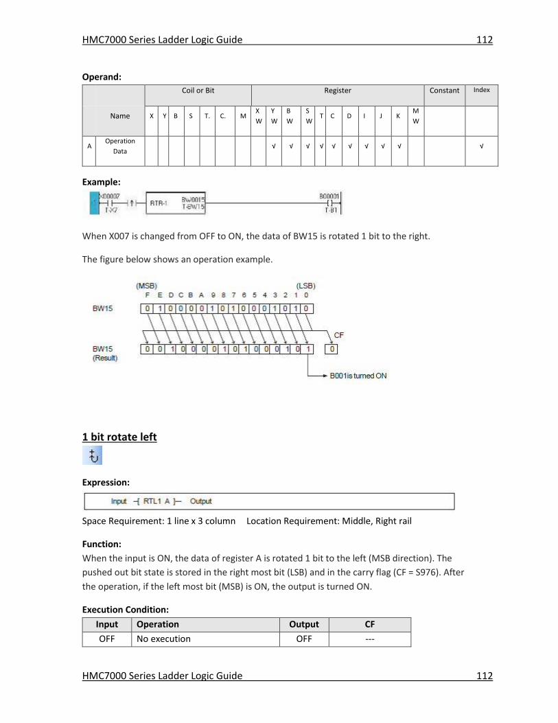
HMC7000 Series Ladder Logic Guide 112
HMC7000 Series Ladder Logic Guide 112
Operand:
Coil or Bit Register Constant Index
Name X Y B S T. C. M
X
W
Y
W
B
W
S
W T C D I J K
M
W
A Operation
Data √ √ √ √ √ √ √ √ √ √
Example:
When X007 is changed from OFF to ON, the data of BW15 is rotated 1 bit to the right.
The figure below shows an operation example.
1 bit rotate left
Expression:
Space Requirement: 1 line x 3 column Location Requirement: Middle, Right rail
Function:
When the input is ON, the data of register A is rotated 1 bit to the left (MSB direction). The
pushed out bit state is stored in the right most bit (LSB) and in the carry flag (CF = S976). After
the operation, if the left most bit (MSB) is ON, the output is turned ON.
Execution Condition:
Input Operation Output CF
OFF No execution OFF ---
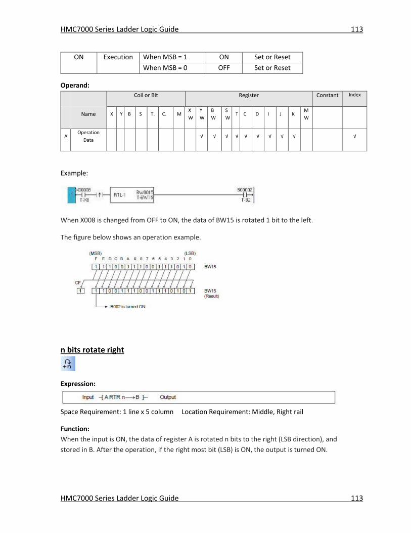
HMC7000 Series Ladder Logic Guide 113
HMC7000 Series Ladder Logic Guide 113
ON Execution When MSB = 1 ON Set or Reset
When MSB = 0 OFF Set or Reset
Operand:
Coil or Bit Register Constant Index
Name X Y B S T. C. M
X
W
Y
W
B
W
S
W T C D I J K
M
W
A Operation
Data √ √ √ √ √ √ √ √ √ √
Example:
When X008 is changed from OFF to ON, the data of BW15 is rotated 1 bit to the left.
The figure below shows an operation example.
n bits rotate right
Expression:
Space Requirement: 1 line x 5 column Location Requirement: Middle, Right rail
Function:
When the input is ON, the data of register A is rotated n bits to the right (LSB direction), and
stored in B. After the operation, if the right most bit (LSB) is ON, the output is turned ON.
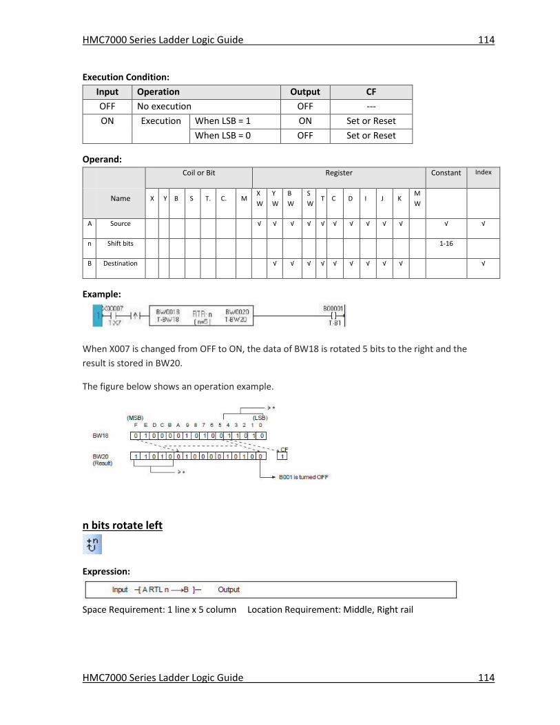
HMC7000 Series Ladder Logic Guide 114
HMC7000 Series Ladder Logic Guide 114
Execution Condition:
Input Operation Output CF
OFF No execution OFF ---
ON Execution When LSB = 1 ON Set or Reset
When LSB = 0 OFF Set or Reset
Operand:
Coil or Bit Register Constant Index
Name X Y B S T. C. M
X
W
Y
W
B
W
S
W T C D I J K
M
W
A Source √ √ √ √ √ √ √ √ √ √ √ √
n Shift bits 1-16
B Destination √ √ √ √ √ √ √ √ √ √
Example:
When X007 is changed from OFF to ON, the data of BW18 is rotated 5 bits to the right and the
result is stored in BW20.
The figure below shows an operation example.
n bits rotate left
Expression:
Space Requirement: 1 line x 5 column Location Requirement: Middle, Right rail
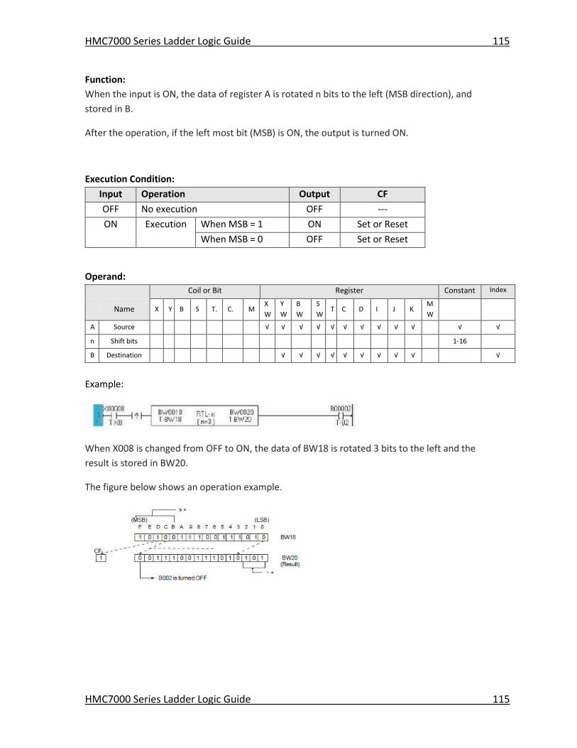
HMC7000 Series Ladder Logic Guide 115
HMC7000 Series Ladder Logic Guide 115
Function:
When the input is ON, the data of register A is rotated n bits to the left (MSB direction), and
stored in B.
After the operation, if the left most bit (MSB) is ON, the output is turned ON.
Execution Condition:
Input Operation Output CF
OFF No execution OFF ---
ON Execution When MSB = 1 ON Set or Reset
When MSB = 0 OFF Set or Reset
Operand:
Coil or Bit Register Constant Index
Name X Y B S T. C. M
X
W
Y
W
B
W
S
W T C D I J K
M
W
A Source √ √ √ √ √ √ √ √ √ √ √ √
n Shift bits 1-16
B Destination √ √ √ √ √ √ √ √ √ √
Example:
When X008 is changed from OFF to ON, the data of BW18 is rotated 3 bits to the left and the
result is stored in BW20.
The figure below shows an operation example.
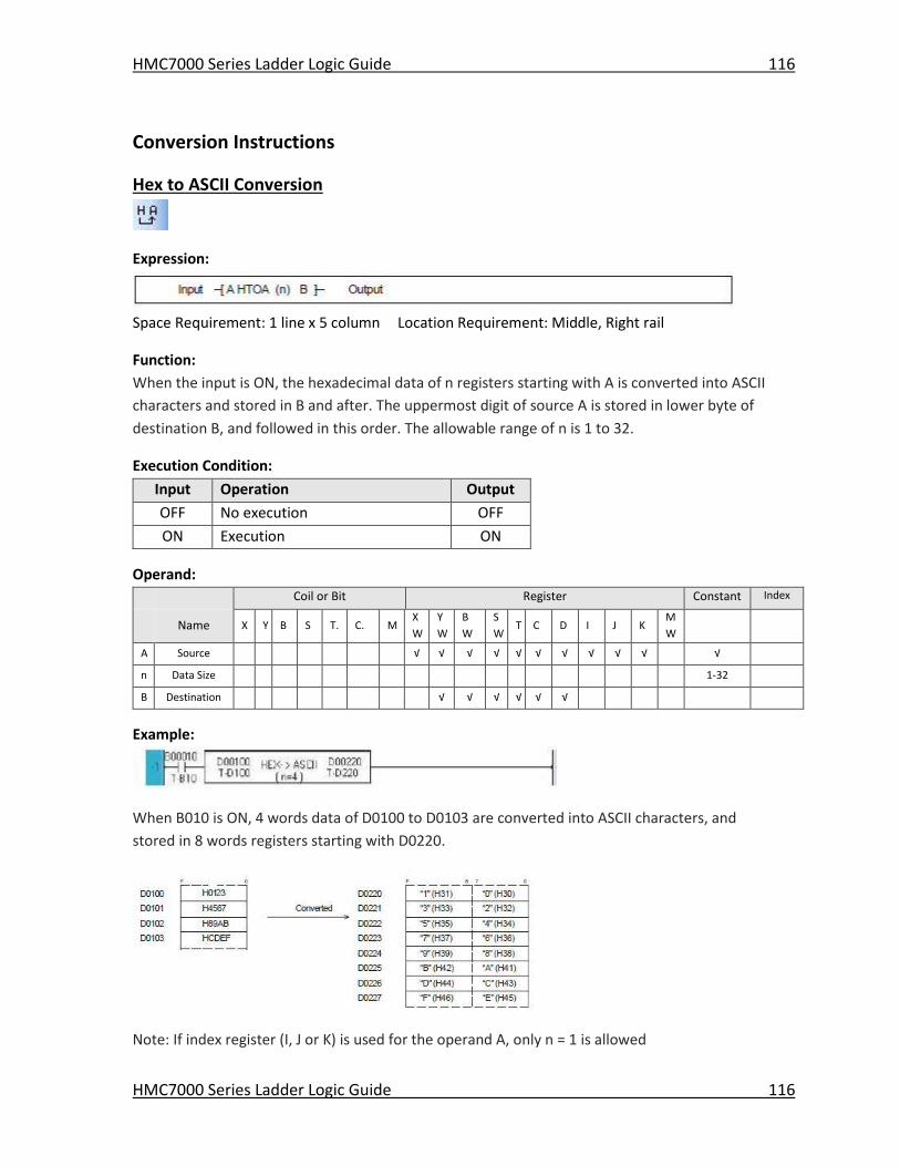
HMC7000 Series Ladder Logic Guide 116
HMC7000 Series Ladder Logic Guide 116
Conversion Instructions
Hex to ASCII Conversion
Expression:
Space Requirement: 1 line x 5 column Location Requirement: Middle, Right rail
Function:
When the input is ON, the hexadecimal data of n registers starting with A is converted into ASCII
characters and stored in B and after. The uppermost digit of source A is stored in lower byte of
destination B, and followed in this order. The allowable range of n is 1 to 32.
Execution Condition:
Input Operation Output
OFF No execution OFF
ON Execution ON
Operand:
Coil or Bit Register Constant Index
Name X Y B S T. C. M
X
W
Y
W
B
W
S
W T C D I J K
M
W
A Source √ √ √ √ √ √ √ √ √ √ √
n Data Size 1-32
B Destination √ √ √ √ √ √
Example:
When B010 is ON, 4 words data of D0100 to D0103 are converted into ASCII characters, and
stored in 8 words registers starting with D0220.
Note: If index register (I, J or K) is used for the operand A, only n = 1 is allowed
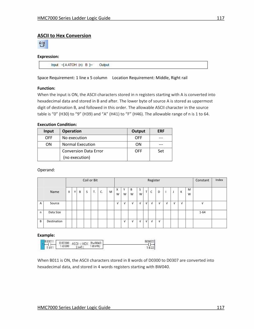
HMC7000 Series Ladder Logic Guide 117
HMC7000 Series Ladder Logic Guide 117
ASCII to Hex Conversion
Expression:
Space Requirement: 1 line x 5 column Location Requirement: Middle, Right rail
Function:
When the input is ON, the ASCII characters stored in n registers starting with A is converted into
hexadecimal data and stored in B and after. The lower byte of source A is stored as uppermost
digit of destination B, and followed in this order. The allowable ASCII character in the source
table is “0” (H30) to “9” (H39) and “A” (H41) to “F” (H46). The allowable range of n is 1 to 64.
Execution Condition:
Input Operation Output ERF
OFF No execution OFF ---
ON Normal Execution ON ---
Conversion Data Error
(no execution)
OFF Set
Operand:
Coil or Bit Register Constant Index
Name X Y B S T. C. M
X
W
Y
W
B
W
S
W T C D I J K
M
W
A Source √ √ √ √ √ √ √ √ √ √ √
n Data Size 1-64
B Destination √ √ √ √ √ √
Example:
When B011 is ON, the ASCII characters stored in 8 words of D0300 to D0307 are converted into
hexadecimal data, and stored in 4 words registers starting with BW040.
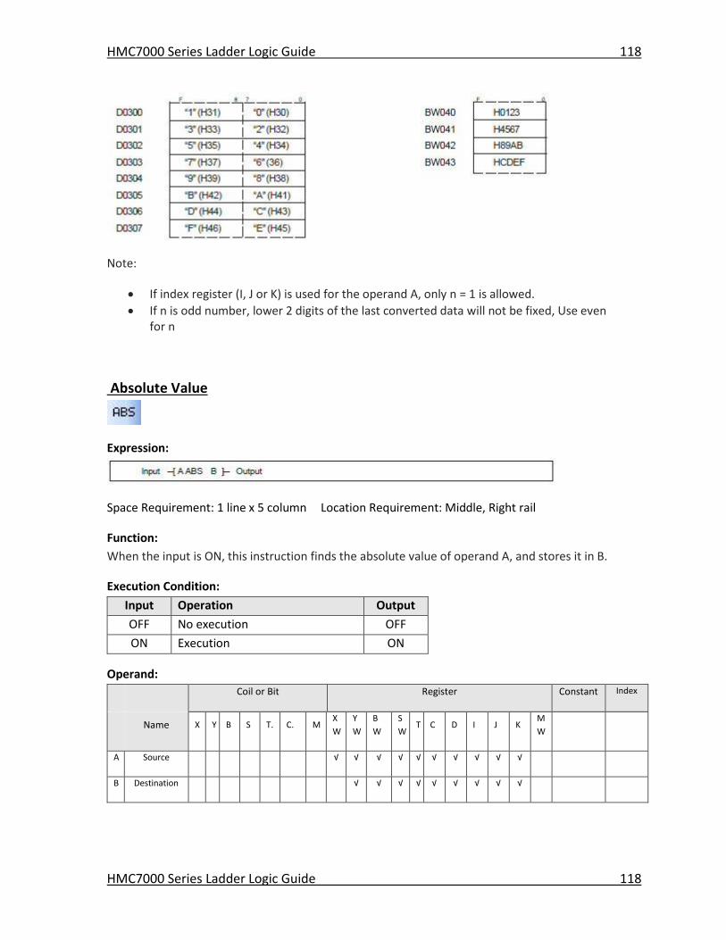
HMC7000 Series Ladder Logic Guide 118
HMC7000 Series Ladder Logic Guide 118
Note:
If index register (I, J or K) is used for the operand A, only n = 1 is allowed.
If n is odd number, lower 2 digits of the last converted data will not be fixed, Use even for n
Absolute Value
Expression:
Space Requirement: 1 line x 5 column Location Requirement: Middle, Right rail
Function:
When the input is ON, this instruction finds the absolute value of operand A, and stores it in B.
Execution Condition:
Input Operation Output
OFF No execution OFF
ON Execution ON
Operand:
Coil or Bit Register Constant Index
Name X Y B S T. C. M
X
W
Y
W
B
W
S
W T C D I J K
M
W
A Source √ √ √ √ √ √ √ √ √ √
B Destination √ √ √ √ √ √ √ √ √
HMC7000 Series Ladder Logic Guide 119
HMC7000 Series Ladder Logic Guide 119
Example:
When X006 is ON, the absolute value of BW38 is stored in D0121.
For example, if BW38 is -12000, the absolute value 12000 is stored in D0121.
Note: The data range of A is -32768 to 32767. If the data of A is -32768, then 32767 is stored in
B.
2’s Complement
Expression:
Space Requirement: 1 line x 5 column Location Requirement: Middle, Right rail
Function:
When the input is ON, this instruction finds the 2’s compliment value of A, and stores it in B.
Execution Condition:
Input Operation Output
OFF No execution OFF
ON Execution ON
Operand:
Coil or Bit Register Constant Index
Name X Y B S T. C. M
X
W
Y
W
B
W
S
W T C D I J K
M
W
A Source √ √ √ √ √ √ √ √ √ √ √
HMC7000 Series Ladder Logic Guide 120
HMC7000 Series Ladder Logic Guide 120
B Destination √ √ √ √ √ √ √ √ √
Example:
When X007 is ON, the 2’s complement value (sign inverted data) of BW39 is stored in D0122.
For example, if BW38 is 4660, the 2’s complement value -4660 is stored in D0122.
2’s complement data is calculated as follows.
Note: The data range of A is -32768 to 32767. If the data of A is -32768, the same data -32768 is
stored in B.
Double-word 2’s Complement
Expression:
Space Requirement: 1 line x 5 column Location Requirement: Middle, Right rail
Function:
When the input is ON, this instruction finds the 2’s complement value of double-word data
A+1×A, and stores it in B+1×B..
Execution Condition:
Input Operation Output
OFF No execution OFF
ON Execution ON
Operand:
Coil or Bit Register Constant Index
HMC7000 Series Ladder Logic Guide 121
HMC7000 Series Ladder Logic Guide 121
Name X Y B S T. C. M
X
W
Y
W
B
W
S
W T C D I J K
M
W
A Source √ √ √ √ √ √ √ √
B Destination √ √ √ √ √ √
Example:
When X007 is ON, the 2’s complement value (sign inverted data) of double-word register
BW41×BW40 is stored in double-word register D0051×D0050.
For example, if BW41×BW40 is -1234567890, the 2’s complement value 1234567890 is stored in
D0051×D0050.
Note: The data range of A+1× A is -2147483648 to 2147483647. If the data of A+1× A is -
2147483648, the same data -2147483648 is stored in B+1× B.
7 Segment Decode
Expression:
Space Requirement: 1 line x 5 column Location Requirement: Middle, Right rail
Function:
When the input is ON, this instruction converts the lower 4 bits data of A into the 7 segment
code, and stores it in B. The 7 segment code is normally used for a numeric display LED.
Execution Condition:
Input Operation Output
OFF No execution OFF
ON Execution ON
Operand:
Coil or Bit Register Constant Index
Name X Y B S T. C. M
X
W
Y
W
B
W
S
W T C D I J K
M
W
HMC7000 Series Ladder Logic Guide 122
HMC7000 Series Ladder Logic Guide 122
A Source √ √ √ √ √ √ √ √ √ √ √
B Destination √ √ √ √ √ √ √ √ √
Example:
When X000 is ON, the lower 4 bits data of BW15 is converted into the 7 segment code, and the
result is stored in lower 8 bits of BW10. 0 is stored in upper 8 bits of BW10.
For example, if BW15 is H0009, the corresponding 7 segment code H006F is stored in BW1.
The 7 segment code conversion table is shown on the next page.
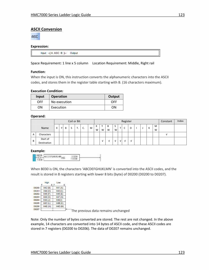
HMC7000 Series Ladder Logic Guide 123
HMC7000 Series Ladder Logic Guide 123
ASCII Conversion
Expression:
Space Requirement: 1 line x 5 column Location Requirement: Middle, Right rail
Function:
When the input is ON, this instruction converts the alphanumeric characters into the ASCII
codes, and stores them in the register table starting with B. (16 characters maximum).
Execution Condition:
Input Operation Output
OFF No execution OFF
ON Execution ON
Operand:
Coil or Bit Register Constant Index
Name X Y B S T. C. M
X
W
Y
W
B
W
S
W T C D I J K
M
W
A Characters √
B Start of
Destination √ √ √ √ √ √
Example:
When B030 is ON, the characters ‘ABCDEFGHIJKLMN’ is converted into the ASCII codes, and the
result is stored in 8 registers starting with lower 8 bits (byte) of D0200 (D0200 to D0207).
The previous data remains unchanged
Note: Only the number of bytes converted are stored. The rest are not changed. In the above example, 14 characters are converted into 14 bytes of ASCII code, and these ASCII codes are stored in 7 registers (D0200 to D0206). The data of D0207 remains unchanged.
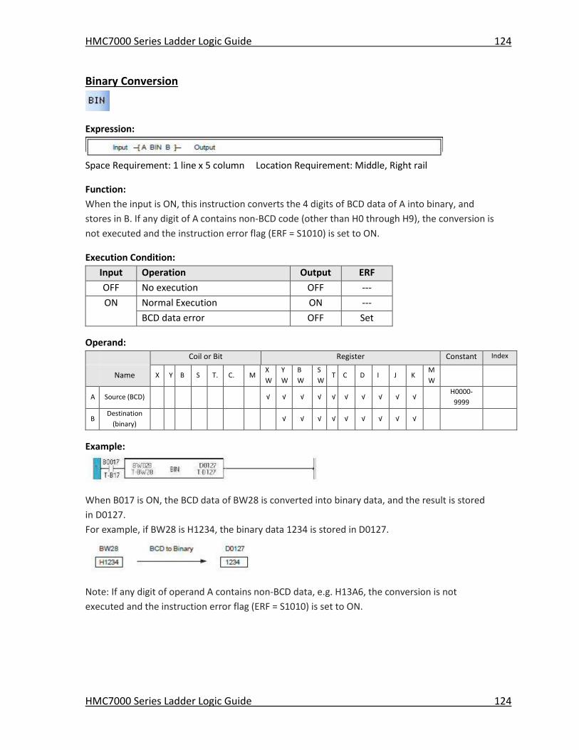
HMC7000 Series Ladder Logic Guide 124
HMC7000 Series Ladder Logic Guide 124
Binary Conversion
Expression:
Space Requirement: 1 line x 5 column Location Requirement: Middle, Right rail
Function:
When the input is ON, this instruction converts the 4 digits of BCD data of A into binary, and
stores in B. If any digit of A contains non-BCD code (other than H0 through H9), the conversion is
not executed and the instruction error flag (ERF = S1010) is set to ON.
Execution Condition:
Input Operation Output ERF
OFF No execution OFF ---
ON Normal Execution ON ---
BCD data error OFF Set
Operand:
Coil or Bit Register Constant Index
Name X Y B S T. C. M
X
W
Y
W
B
W
S
W T C D I J K
M
W
A Source (BCD) √ √ √ √ √ √ √ √ √ √ H0000-
9999
B Destination
(binary) √ √ √ √ √ √ √ √ √
Example:
When B017 is ON, the BCD data of BW28 is converted into binary data, and the result is stored
in D0127.
For example, if BW28 is H1234, the binary data 1234 is stored in D0127.
Note: If any digit of operand A contains non-BCD data, e.g. H13A6, the conversion is not
executed and the instruction error flag (ERF = S1010) is set to ON.
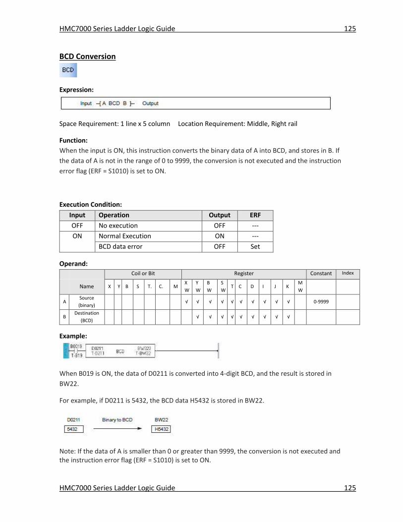
HMC7000 Series Ladder Logic Guide 125
HMC7000 Series Ladder Logic Guide 125
BCD Conversion
Expression:
Space Requirement: 1 line x 5 column Location Requirement: Middle, Right rail
Function:
When the input is ON, this instruction converts the binary data of A into BCD, and stores in B. If
the data of A is not in the range of 0 to 9999, the conversion is not executed and the instruction
error flag (ERF = S1010) is set to ON.
Execution Condition:
Input Operation Output ERF
OFF No execution OFF ---
ON Normal Execution ON ---
BCD data error OFF Set
Operand:
Coil or Bit Register Constant Index
Name X Y B S T. C. M
X
W
Y
W
B
W
S
W T C D I J K
M
W
A Source
(binary) √ √ √ √ √ √ √ √ √ √ 0-9999
B Destination
(BCD) √ √ √ √ √ √ √ √ √
Example:
When B019 is ON, the data of D0211 is converted into 4-digit BCD, and the result is stored in
BW22.
For example, if D0211 is 5432, the BCD data H5432 is stored in BW22.
Note: If the data of A is smaller than 0 or greater than 9999, the conversion is not executed and the instruction error flag (ERF = S1010) is set to ON.
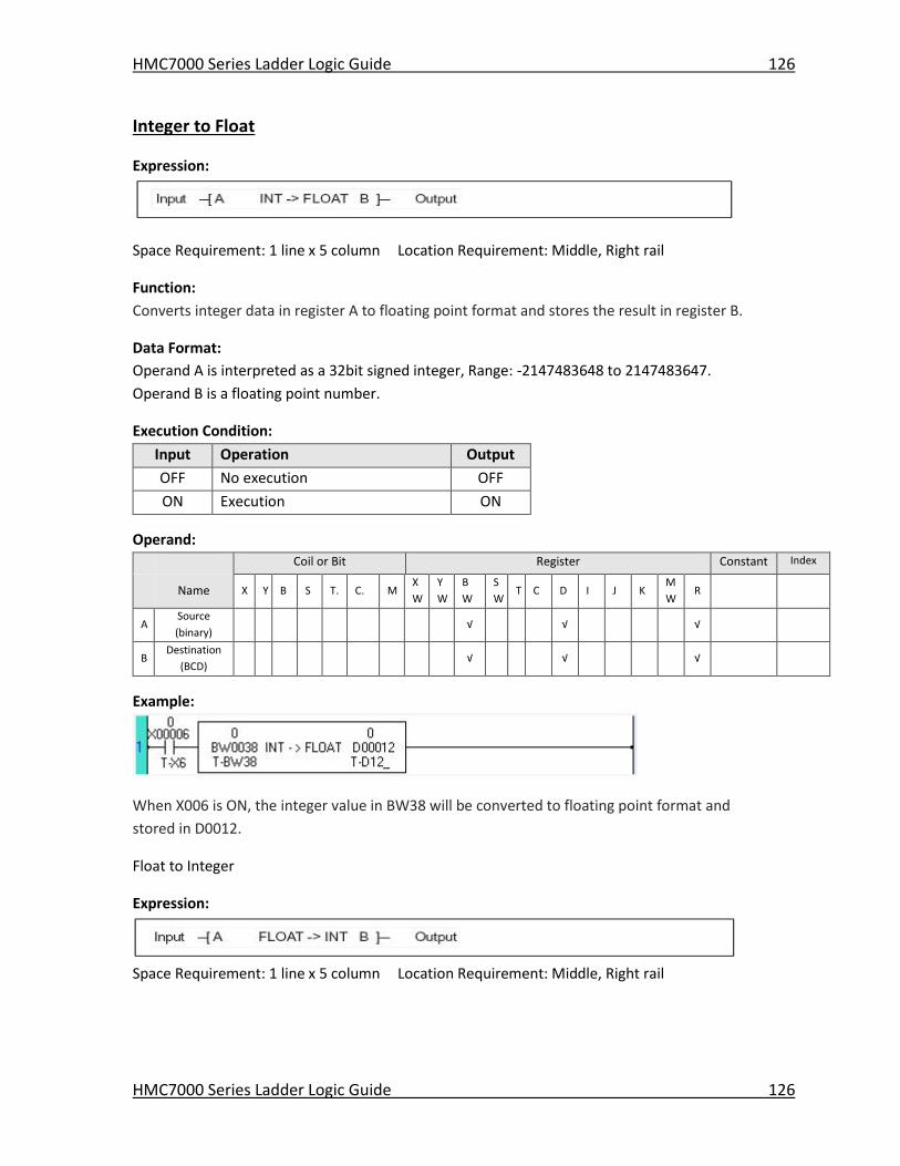
HMC7000 Series Ladder Logic Guide 126
HMC7000 Series Ladder Logic Guide 126
Integer to Float
Expression:
Space Requirement: 1 line x 5 column Location Requirement: Middle, Right rail
Function:
Converts integer data in register A to floating point format and stores the result in register B.
Data Format:
Operand A is interpreted as a 32bit signed integer, Range: -2147483648 to 2147483647.
Operand B is a floating point number.
Execution Condition:
Input Operation Output
OFF No execution OFF
ON Execution ON
Operand:
Coil or Bit Register Constant Index
Name X Y B S T. C. M
X
W
Y
W
B
W
S
W T C D I J K
M
W R
A Source
(binary) √ √ √
B Destination
(BCD) √ √ √
Example:
When X006 is ON, the integer value in BW38 will be converted to floating point format and
stored in D0012.
Float to Integer
Expression:
Space Requirement: 1 line x 5 column Location Requirement: Middle, Right rail

HMC7000 Series Ladder Logic Guide 127
HMC7000 Series Ladder Logic Guide 127
Function:
Converts a floating point number from register A to a double word signed integer and stores the
result in register B. The converted value is set to the equivalent float value rounded to the
nearest integer.
If the floating point value is outside of the range for a double word signed integer (-2147483648
to 2147483647) the maximum or minimum value is written to operand B and the output is set
OFF. If the float value is within the range of a double word signed integer the value is converted
and the output is set ON.
Data Format:
Operand A is a floating point number, and is converted to a double word signed integer. Range: -
2147483648 to 2147483648
Execution Condition:
Input Operation Output
OFF No execution OFF
ON Execution ON
Operand:
Coil or Bit Register Constant Index
Name X Y B S T. C. M
X
W
Y
W
B
W
S
W T C D I J K
M
W R
A Source
(binary) √ √ √
B Destination
(BCD) √ √ √
Example:
When X006 is ON, the floating point value in BW38 will be converted to a double word signed
integer and the result is stored in D0012.
For example if the float value is 13.7, it is converted to 14. If the float value is 12.3 it is converted
to 12.
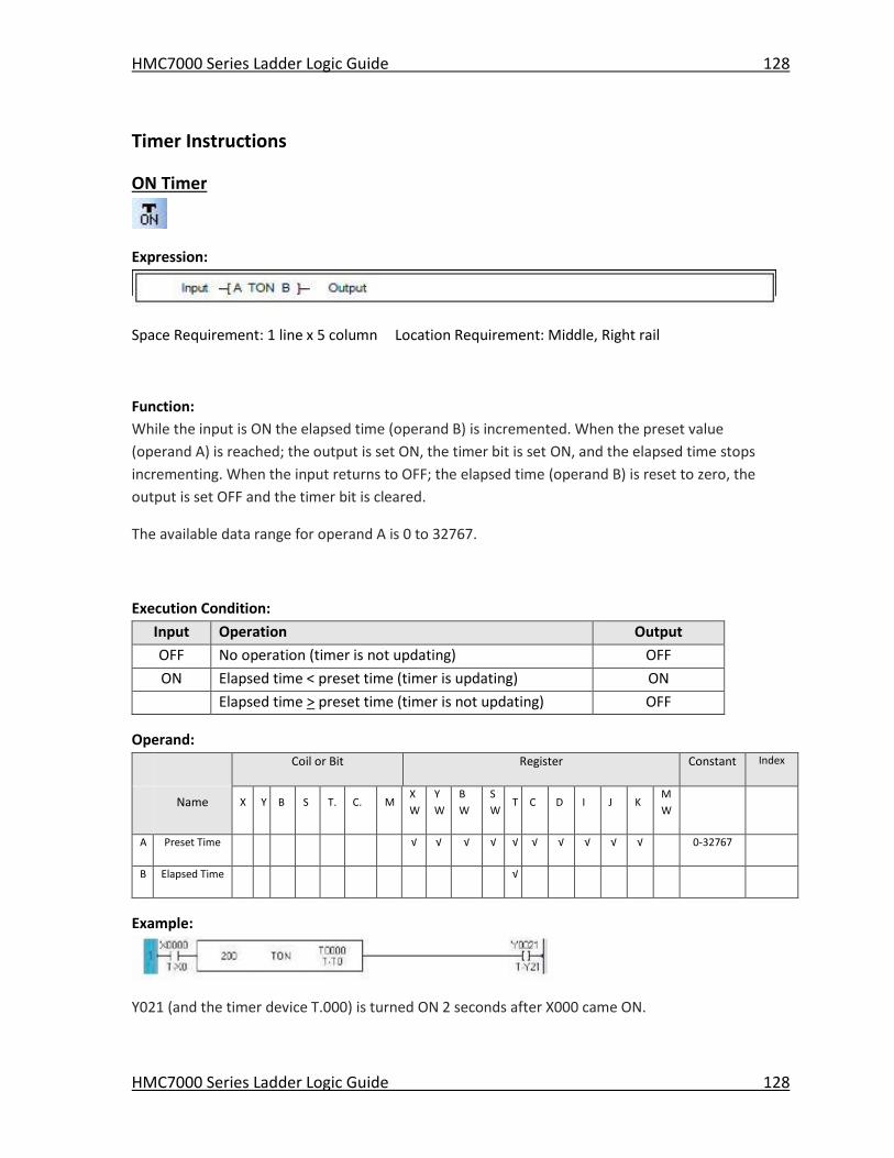
HMC7000 Series Ladder Logic Guide 128
HMC7000 Series Ladder Logic Guide 128
Timer Instructions
ON Timer
Expression:
Space Requirement: 1 line x 5 column Location Requirement: Middle, Right rail
Function:
While the input is ON the elapsed time (operand B) is incremented. When the preset value
(operand A) is reached; the output is set ON, the timer bit is set ON, and the elapsed time stops
incrementing. When the input returns to OFF; the elapsed time (operand B) is reset to zero, the
output is set OFF and the timer bit is cleared.
The available data range for operand A is 0 to 32767.
Execution Condition:
Input Operation Output
OFF No operation (timer is not updating) OFF
ON Elapsed time < preset time (timer is updating) ON
Elapsed time > preset time (timer is not updating) OFF
Operand:
Coil or Bit Register Constant Index
Name X Y B S T. C. M
X
W
Y
W
B
W
S
W T C D I J K
M
W
A Preset Time √ √ √ √ √ √ √ √ √ √ 0-32767
B Elapsed Time √
Example:
Y021 (and the timer device T.000) is turned ON 2 seconds after X000 came ON.
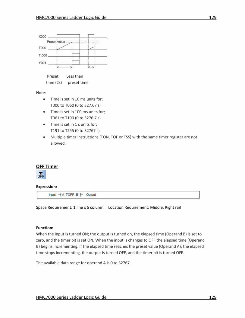
HMC7000 Series Ladder Logic Guide 129
HMC7000 Series Ladder Logic Guide 129
Preset Less than
time (2s) preset time
Note:
Time is set in 10 ms units for;
T000 to T060 (0 to 327.67 s)
Time is set in 100 ms units for;
T061 to T190 (0 to 3276.7 s)
Time is set in 1 s units for;
T191 to T255 (0 to 32767 s)
Multiple timer instructions (TON, TOF or TSS) with the same timer register are not
allowed.
OFF Timer
Expression:
Space Requirement: 1 line x 5 column Location Requirement: Middle, Right rail
Function:
When the input is turned ON; the output is turned on, the elapsed time (Operand B) is set to
zero, and the timer bit is set ON. When the input is changes to OFF the elapsed time (Operand
B) begins incrementing. If the elapsed time reaches the preset value (Operand A); the elapsed
time stops incrementing, the output is turned OFF, and the timer bit is turned OFF.
The available data range for operand A is 0 to 32767.
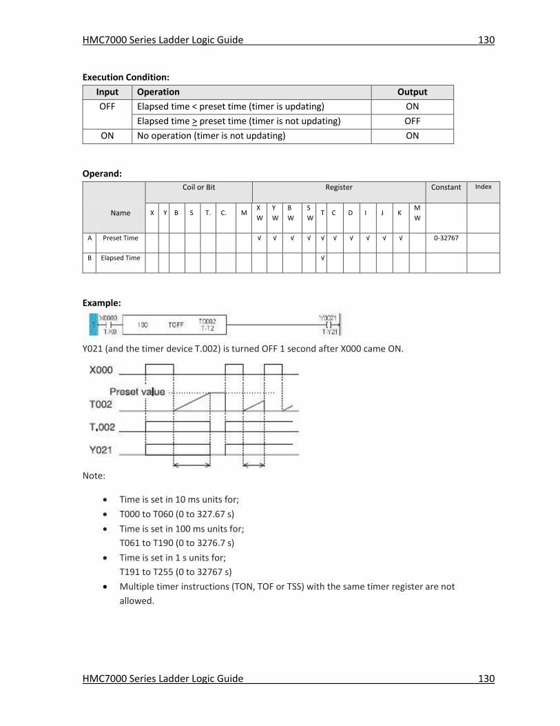
HMC7000 Series Ladder Logic Guide 130
HMC7000 Series Ladder Logic Guide 130
Execution Condition:
Input Operation Output
OFF Elapsed time < preset time (timer is updating) ON
Elapsed time > preset time (timer is not updating) OFF
ON No operation (timer is not updating) ON
Operand:
Coil or Bit Register Constant Index
Name X Y B S T. C. M
X
W
Y
W
B
W
S
W T C D I J K
M
W
A Preset Time √ √ √ √ √ √ √ √ √ √ 0-32767
B Elapsed Time √
Example:
Y021 (and the timer device T.002) is turned OFF 1 second after X000 came ON.
Note:
Time is set in 10 ms units for;
T000 to T060 (0 to 327.67 s)
Time is set in 100 ms units for;
T061 to T190 (0 to 3276.7 s)
Time is set in 1 s units for;
T191 to T255 (0 to 32767 s)
Multiple timer instructions (TON, TOF or TSS) with the same timer register are not
allowed.
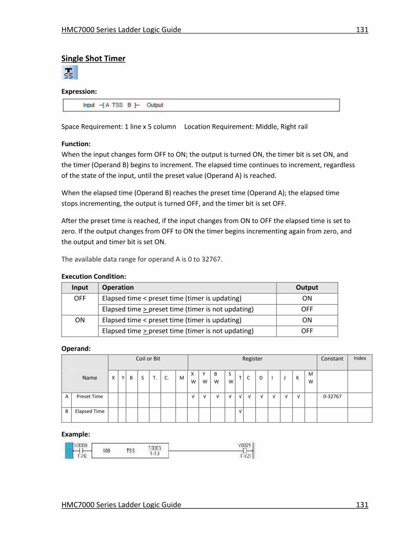
HMC7000 Series Ladder Logic Guide 131
HMC7000 Series Ladder Logic Guide 131
Single Shot Timer
Expression:
Space Requirement: 1 line x 5 column Location Requirement: Middle, Right rail
Function:
When the input changes form OFF to ON; the output is turned ON, the timer bit is set ON, and
the timer (Operand B) begins to increment. The elapsed time continues to increment, regardless
of the state of the input, until the preset value (Operand A) is reached.
When the elapsed time (Operand B) reaches the preset time (Operand A); the elapsed time
stops incrementing, the output is turned OFF, and the timer bit is set OFF.
After the preset time is reached, if the input changes from ON to OFF the elapsed time is set to
zero. If the output changes from OFF to ON the timer begins incrementing again from zero, and
the output and timer bit is set ON.
The available data range for operand A is 0 to 32767.
Execution Condition:
Input Operation Output
OFF Elapsed time < preset time (timer is updating) ON
Elapsed time > preset time (timer is not updating) OFF
ON Elapsed time < preset time (timer is updating) ON
Elapsed time > preset time (timer is not updating) OFF
Operand:
Coil or Bit Register Constant Index
Name X Y B S T. C. M
X
W
Y
W
B
W
S
W T C D I J K
M
W
A Preset Time √ √ √ √ √ √ √ √ √ √ 0-32767
B Elapsed Time √
Example:
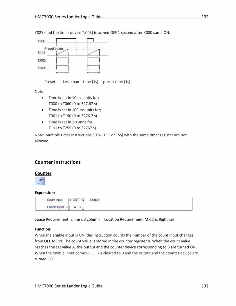
HMC7000 Series Ladder Logic Guide 132
HMC7000 Series Ladder Logic Guide 132
Y021 (and the timer device T.003) is turned OFF 1 second after X000 came ON.
Preset Less than time (1s) preset time (1s)
Note:
Time is set in 10 ms units for;
T000 to T060 (0 to 327.67 s)
Time is set in 100 ms units for;
T061 to T190 (0 to 3276.7 s)
Time is set in 1 s units for;
T191 to T255 (0 to 32767 s)
Note: Multiple timer instructions (TON, TOF or TSS) with the same timer register are not
allowed.
Counter Instructions
Counter
Expression:
Space Requirement: 2 line x 3 column Location Requirement: Middle, Right rail
Function:
While the enable input is ON, this instruction counts the number of the count input changes
from OFF to ON. The count value is stored in the counter register B. When the count value
reaches the set value A, the output and the counter device corresponding to B are turned ON.
When the enable input comes OFF, B is cleared to 0 and the output and the counter device are
turned OFF.
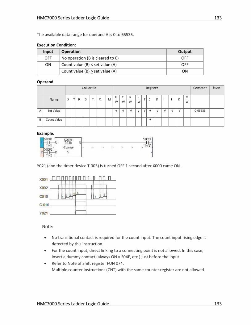
HMC7000 Series Ladder Logic Guide 133
HMC7000 Series Ladder Logic Guide 133
The available data range for operand A is 0 to 65535.
Execution Condition:
Input Operation Output
OFF No operation (B is cleared to 0) OFF
ON Count value (B) < set value (A) OFF
Count value (B) > set value (A) ON
Operand:
Coil or Bit Register Constant Index
Name X Y B S T. C. M
X
W
Y
W
B
W
S
W T C D I J K
M
W
A Set Value √ √ √ √ √ √ √ √ √ √ 0-65535
B Count Value √
Example:
Y021 (and the timer device T.003) is turned OFF 1 second after X000 came ON.
Note:
No transitional contact is required for the count input. The count input rising edge is
detected by this instruction.
For the count input, direct linking to a connecting point is not allowed. In this case,
insert a dummy contact (always ON = S04F, etc.) just before the input.
Refer to Note of Shift register FUN 074.
Multiple counter instructions (CNT) with the same counter register are not allowed
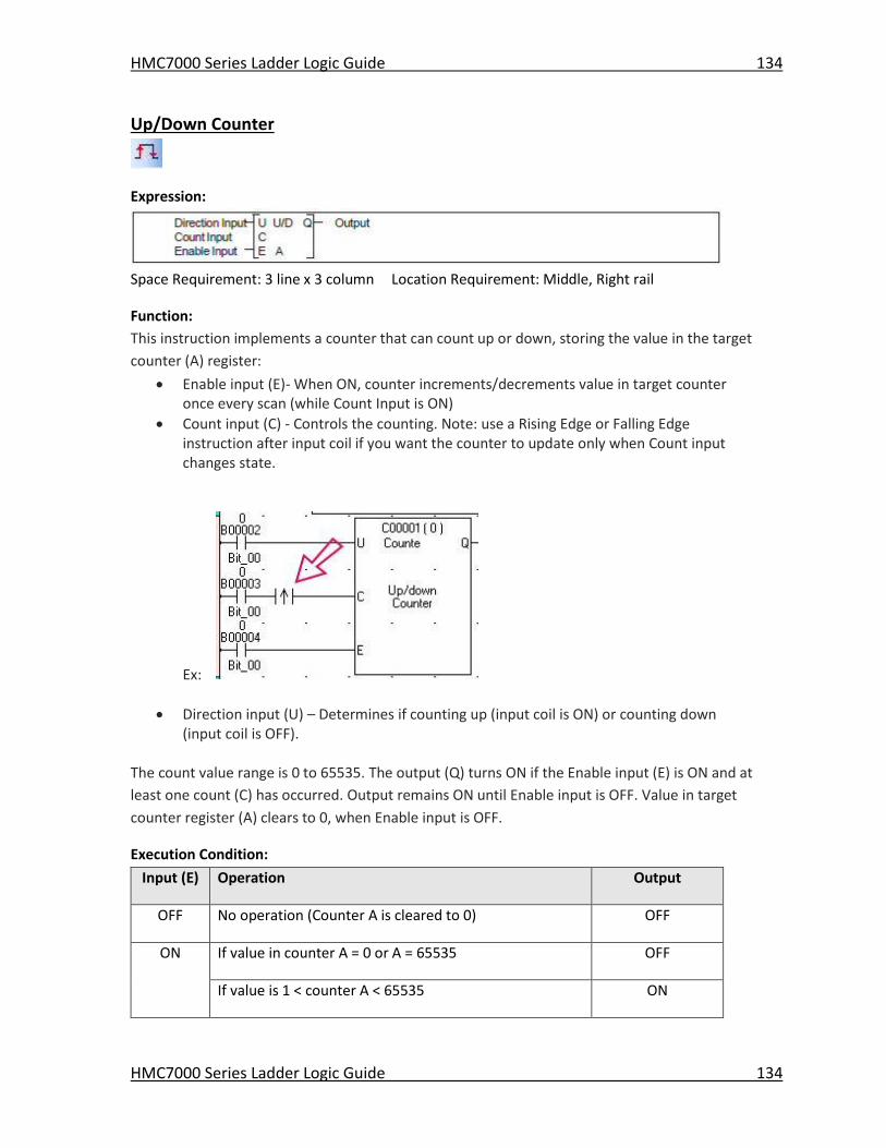
HMC7000 Series Ladder Logic Guide 134
HMC7000 Series Ladder Logic Guide 134
Up/Down Counter
Expression:
Space Requirement: 3 line x 3 column Location Requirement: Middle, Right rail
Function:
This instruction implements a counter that can count up or down, storing the value in the target
counter (A) register:
Enable input (E)- When ON, counter increments/decrements value in target counter once every scan (while Count Input is ON)
Count input (C) - Controls the counting. Note: use a Rising Edge or Falling Edge instruction after input coil if you want the counter to update only when Count input changes state.
Ex:
Direction input (U) – Determines if counting up (input coil is ON) or counting down (input coil is OFF).
The count value range is 0 to 65535. The output (Q) turns ON if the Enable input (E) is ON and at
least one count (C) has occurred. Output remains ON until Enable input is OFF. Value in target
counter register (A) clears to 0, when Enable input is OFF.
Execution Condition:
Input (E) Operation Output
OFF No operation (Counter A is cleared to 0) OFF
ON If value in counter A = 0 or A = 65535 OFF
If value is 1 < counter A < 65535 ON
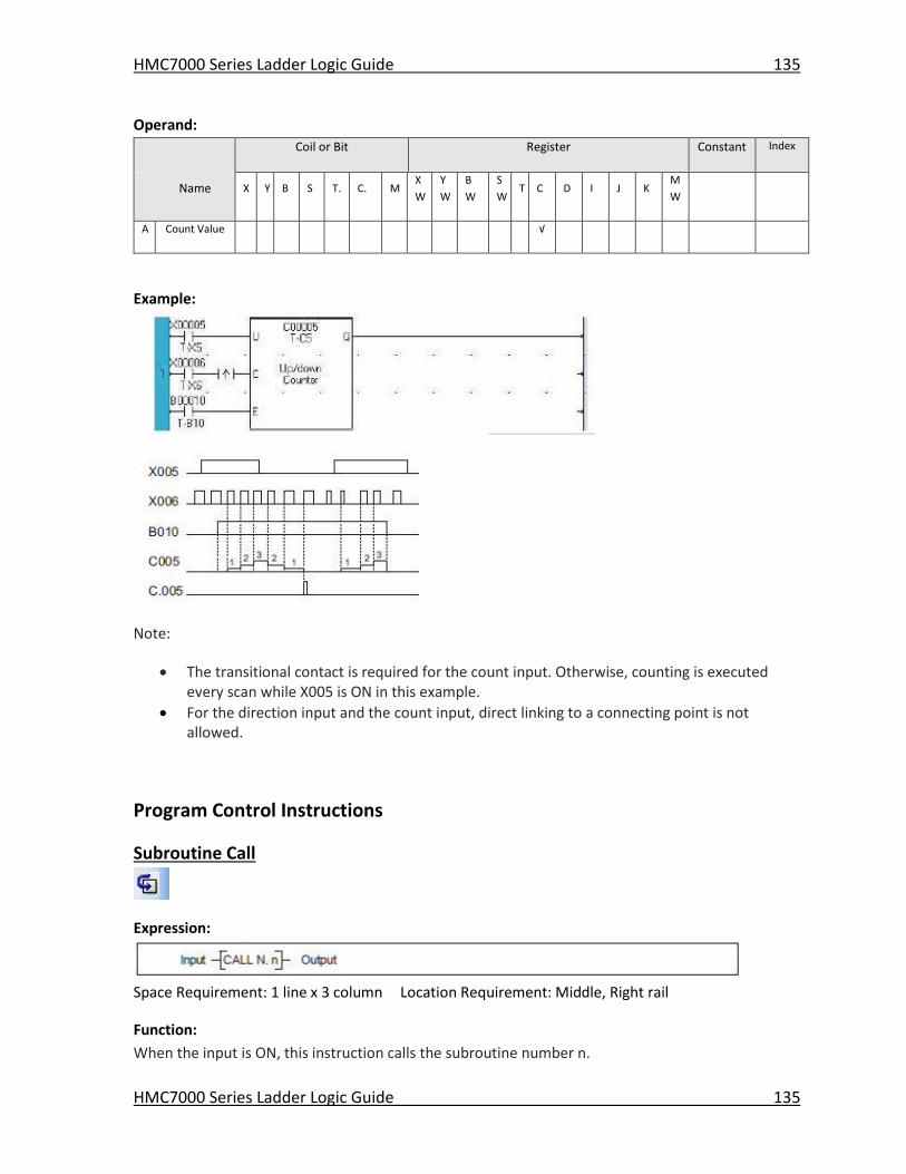
HMC7000 Series Ladder Logic Guide 135
HMC7000 Series Ladder Logic Guide 135
Operand:
Coil or Bit Register Constant Index
Name X Y B S T. C. M
X
W
Y
W
B
W
S
W T C D I J K
M
W
A Count Value √
Example:
Note:
The transitional contact is required for the count input. Otherwise, counting is executed every scan while X005 is ON in this example.
For the direction input and the count input, direct linking to a connecting point is not allowed.
Program Control Instructions
Subroutine Call
Expression:
Space Requirement: 1 line x 3 column Location Requirement: Middle, Right rail
Function:
When the input is ON, this instruction calls the subroutine number n.
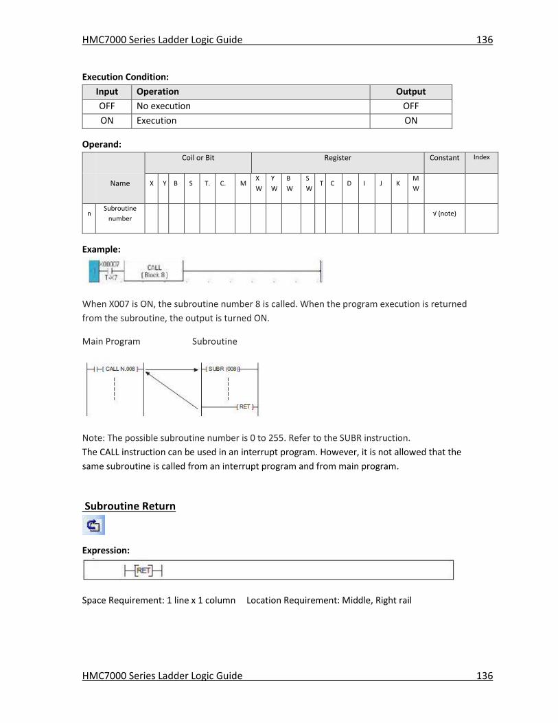
HMC7000 Series Ladder Logic Guide 136
HMC7000 Series Ladder Logic Guide 136
Execution Condition:
Input Operation Output
OFF No execution OFF
ON Execution ON
Operand:
Coil or Bit Register Constant Index
Name X Y B S T. C. M
X
W
Y
W
B
W
S
W T C D I J K
M
W
n Subroutine
number √ (note)
Example:
When X007 is ON, the subroutine number 8 is called. When the program execution is returned
from the subroutine, the output is turned ON.
Main Program Subroutine
Note: The possible subroutine number is 0 to 255. Refer to the SUBR instruction.
The CALL instruction can be used in an interrupt program. However, it is not allowed that the
same subroutine is called from an interrupt program and from main program.
Subroutine Return
Expression:
Space Requirement: 1 line x 1 column Location Requirement: Middle, Right rail
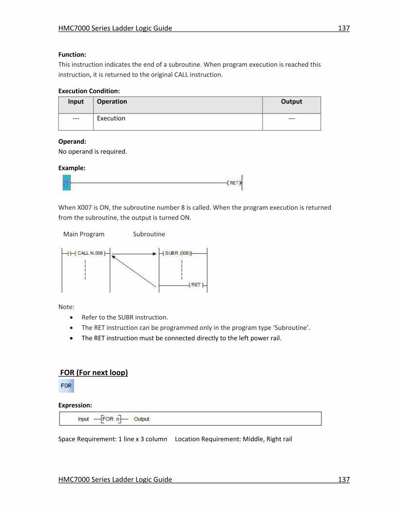
HMC7000 Series Ladder Logic Guide 137
HMC7000 Series Ladder Logic Guide 137
Function:
This instruction indicates the end of a subroutine. When program execution is reached this
instruction, it is returned to the original CALL instruction.
Execution Condition:
Input Operation Output
--- Execution ---
Operand:
No operand is required.
Example:
When X007 is ON, the subroutine number 8 is called. When the program execution is returned
from the subroutine, the output is turned ON.
Main Program Subroutine
Note:
Refer to the SUBR instruction.
The RET instruction can be programmed only in the program type ‘Subroutine’.
The RET instruction must be connected directly to the left power rail.
FOR (For next loop)
Expression:
Space Requirement: 1 line x 3 column Location Requirement: Middle, Right rail
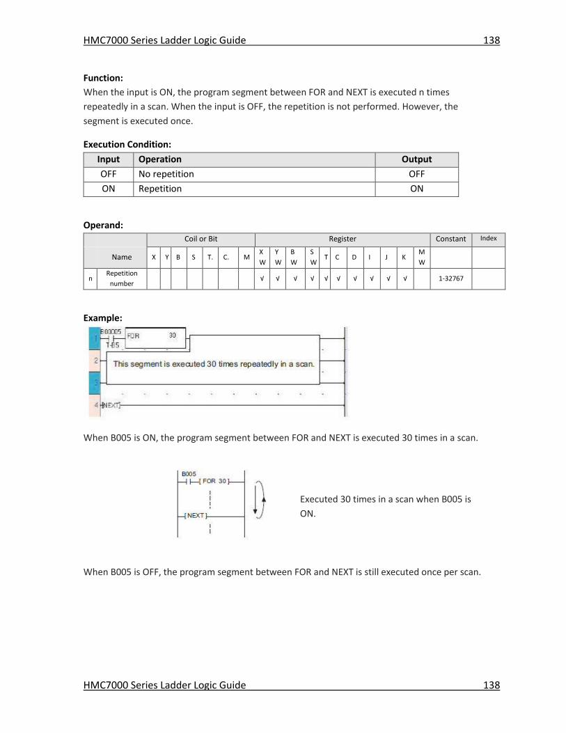
HMC7000 Series Ladder Logic Guide 138
HMC7000 Series Ladder Logic Guide 138
Function:
When the input is ON, the program segment between FOR and NEXT is executed n times
repeatedly in a scan. When the input is OFF, the repetition is not performed. However, the
segment is executed once.
Execution Condition:
Input Operation Output
OFF No repetition OFF
ON Repetition ON
Operand:
Coil or Bit Register Constant Index
Name X Y B S T. C. M
X
W
Y
W
B
W
S
W T C D I J K
M
W
n Repetition
number √ √ √ √ √ √ √ √ √ √ 1-32767
Example:
When B005 is ON, the program segment between FOR and NEXT is executed 30 times in a scan.
Executed 30 times in a scan when B005 is
ON.
When B005 is OFF, the program segment between FOR and NEXT is still executed once per scan.
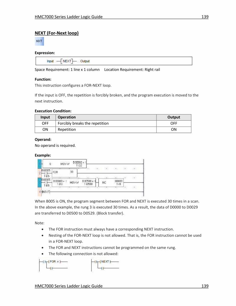
HMC7000 Series Ladder Logic Guide 139
HMC7000 Series Ladder Logic Guide 139
NEXT (For-Next loop)
Expression:
Space Requirement: 1 line x 1 column Location Requirement: Right rail
Function:
This instruction configures a FOR-NEXT loop.
If the input is OFF, the repetition is forcibly broken, and the program execution is moved to the
next instruction.
Execution Condition:
Input Operation Output
OFF Forcibly breaks the repetition OFF
ON Repetition ON
Operand:
No operand is required.
Example:
When B005 is ON, the program segment between FOR and NEXT is executed 30 times in a scan.
In the above example, the rung 3 is executed 30 times. As a result, the data of D0000 to D0029
are transferred to D0500 to D0529. (Block transfer).
Note:
The FOR instruction must always have a corresponding NEXT instruction.
Nesting of the FOR-NEXT loop is not allowed. That is, the FOR instruction cannot be used
in a FOR-NEXT loop.
The FOR and NEXT instructions cannot be programmed on the same rung.
The following connection is not allowed:
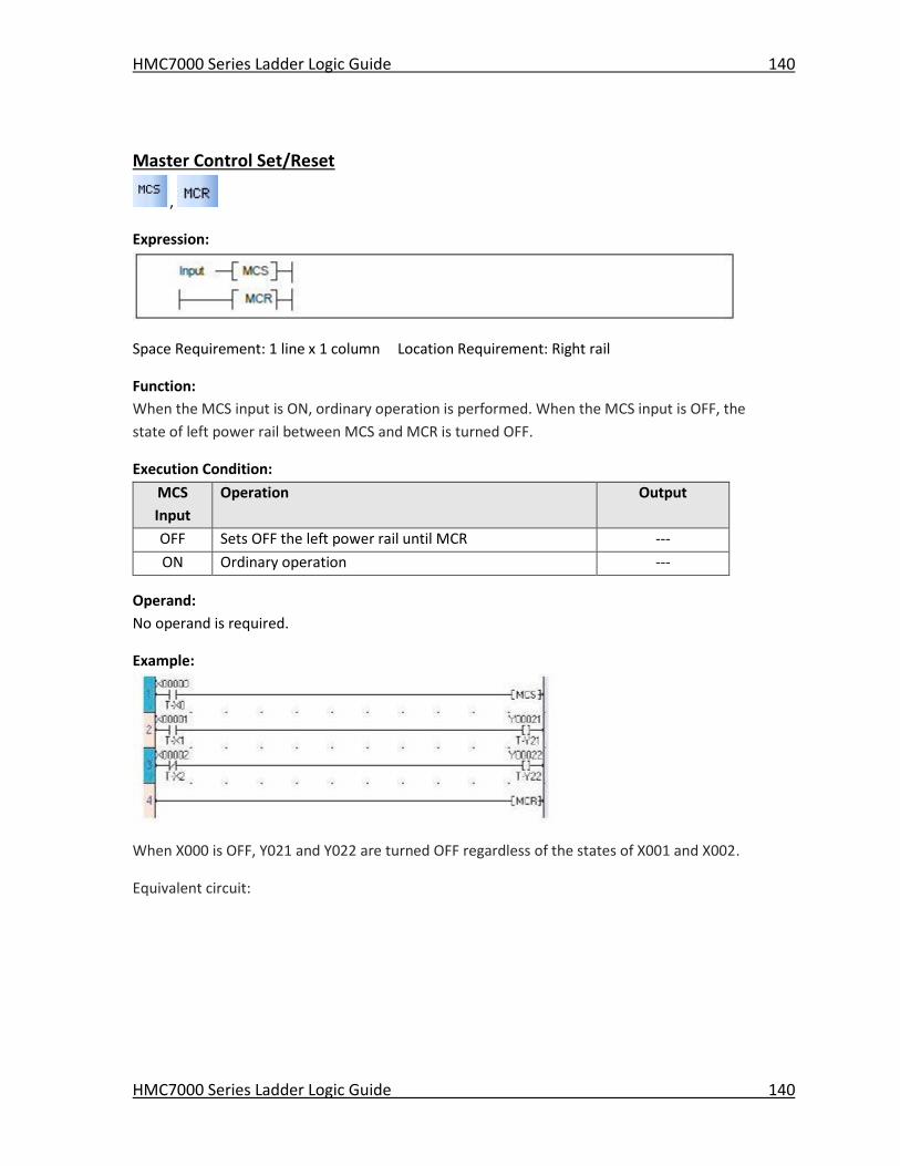
HMC7000 Series Ladder Logic Guide 140
HMC7000 Series Ladder Logic Guide 140
Master Control Set/Reset
,
Expression:
Space Requirement: 1 line x 1 column Location Requirement: Right rail
Function:
When the MCS input is ON, ordinary operation is performed. When the MCS input is OFF, the
state of left power rail between MCS and MCR is turned OFF.
Execution Condition:
MCS
Input
Operation Output
OFF Sets OFF the left power rail until MCR ---
ON Ordinary operation ---
Operand:
No operand is required.
Example:
When X000 is OFF, Y021 and Y022 are turned OFF regardless of the states of X001 and X002.
Equivalent circuit:
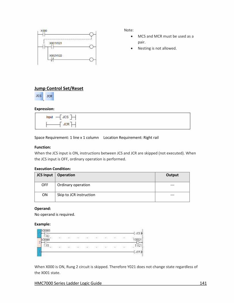
HMC7000 Series Ladder Logic Guide 141
Note:
MCS and MCR must be used as a
pair.
Nesting is not allowed.
Jump Control Set/Reset
,
Expression:
Space Requirement: 1 line x 1 column Location Requirement: Right rail
Function:
When the JCS input is ON, instructions between JCS and JCR are skipped (not executed). When
the JCS input is OFF, ordinary operation is performed.
Execution Condition:
JCS Input Operation Output
OFF Ordinary operation ---
ON Skip to JCR instruction ---
Operand:
No operand is required.
Example:
When X000 is ON, Rung 2 circuit is skipped. Therefore Y021 does not change state regardless of
the X001 state.
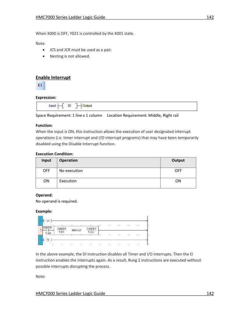
HMC7000 Series Ladder Logic Guide 142
HMC7000 Series Ladder Logic Guide 142
When X000 is OFF, Y021 is controlled by the X001 state.
Note:
JCS and JCR must be used as a pair.
Nesting is not allowed.
Enable Interrupt
Expression:
Space Requirement: 1 line x 1 column Location Requirement: Middle, Right rail
Function:
When the input is ON, this instruction allows the execution of user designated interrupt
operations (i.e. timer interrupt and I/O interrupt programs) that may have been temporarily
disabled using the Disable Interrupt function.
Execution Condition:
Input Operation Output
OFF No execution OFF
ON Execution ON
Operand:
No operand is required.
Example:
In the above example, the DI instruction disables all Timer and I/O interrupts. Then the EI
instruction enables the interrupts again. As a result, Rung 2 instructions are executed without
possible interrupts disrupting the process.
Note:
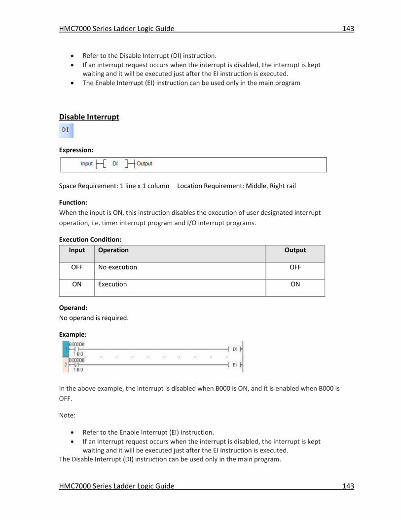
HMC7000 Series Ladder Logic Guide 143
HMC7000 Series Ladder Logic Guide 143
Refer to the Disable Interrupt (DI) instruction.
If an interrupt request occurs when the interrupt is disabled, the interrupt is kept waiting and it will be executed just after the EI instruction is executed.
The Enable Interrupt (EI) instruction can be used only in the main program
Disable Interrupt
Expression:
Space Requirement: 1 line x 1 column Location Requirement: Middle, Right rail
Function:
When the input is ON, this instruction disables the execution of user designated interrupt
operation, i.e. timer interrupt program and I/O interrupt programs.
Execution Condition:
Input Operation Output
OFF No execution OFF
ON Execution ON
Operand:
No operand is required.
Example:
In the above example, the interrupt is disabled when B000 is ON, and it is enabled when B000 is
OFF.
Note:
Refer to the Enable Interrupt (EI) instruction.
If an interrupt request occurs when the interrupt is disabled, the interrupt is kept waiting and it will be executed just after the EI instruction is executed.
The Disable Interrupt (DI) instruction can be used only in the main program.
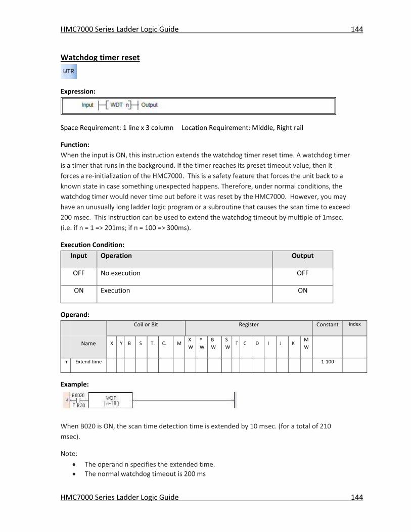
HMC7000 Series Ladder Logic Guide 144
HMC7000 Series Ladder Logic Guide 144
Watchdog timer reset
Expression:
Space Requirement: 1 line x 3 column Location Requirement: Middle, Right rail
Function:
When the input is ON, this instruction extends the watchdog timer reset time. A watchdog timer
is a timer that runs in the background. If the timer reaches its preset timeout value, then it
forces a re-initialization of the HMC7000. This is a safety feature that forces the unit back to a
known state in case something unexpected happens. Therefore, under normal conditions, the
watchdog timer would never time out before it was reset by the HMC7000. However, you may
have an unusually long ladder logic program or a subroutine that causes the scan time to exceed
200 msec. This instruction can be used to extend the watchdog timeout by multiple of 1msec.
(i.e. if n = 1 => 201ms; if n = 100 => 300ms).
Execution Condition:
Input Operation Output
OFF No execution OFF
ON Execution ON
Operand:
Coil or Bit Register Constant Index
Name X Y B S T. C. M
X
W
Y
W
B
W
S
W T C D I J K
M
W
n Extend time 1-100
Example:
When B020 is ON, the scan time detection time is extended by 10 msec. (for a total of 210
msec).
Note:
The operand n specifies the extended time.
The normal watchdog timeout is 200 ms
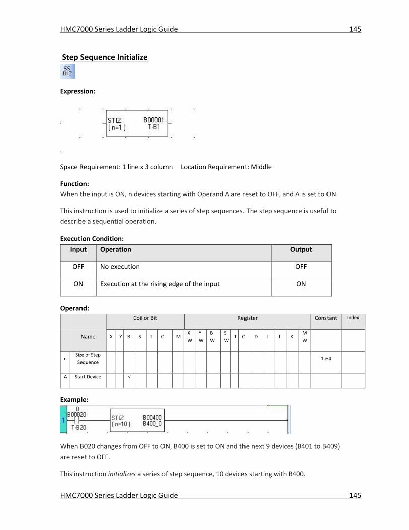
HMC7000 Series Ladder Logic Guide 145
HMC7000 Series Ladder Logic Guide 145
Step Sequence Initialize
Expression:
Space Requirement: 1 line x 3 column Location Requirement: Middle
Function:
When the input is ON, n devices starting with Operand A are reset to OFF, and A is set to ON.
This instruction is used to initialize a series of step sequences. The step sequence is useful to
describe a sequential operation.
Execution Condition:
Input Operation Output
OFF No execution OFF
ON Execution at the rising edge of the input ON
Operand:
Coil or Bit Register Constant Index
Name X Y B S T. C. M
X
W
Y
W
B
W
S
W T C D I J K
M
W
n Size of Step
Sequence 1-64
A Start Device √
Example:
When B020 changes from OFF to ON, B400 is set to ON and the next 9 devices (B401 to B409)
are reset to OFF.
This instruction initializes a series of step sequence, 10 devices starting with B400.
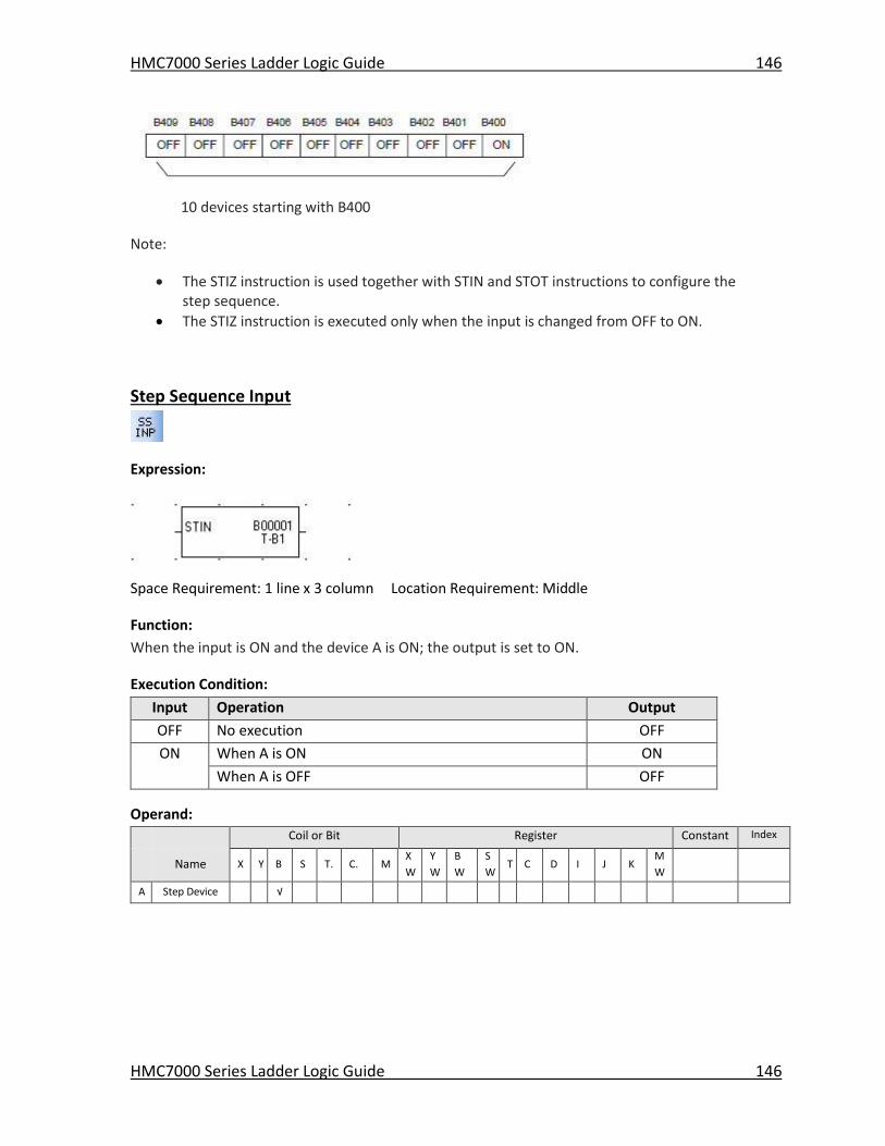
HMC7000 Series Ladder Logic Guide 146
HMC7000 Series Ladder Logic Guide 146
10 devices starting with B400
Note:
The STIZ instruction is used together with STIN and STOT instructions to configure the step sequence.
The STIZ instruction is executed only when the input is changed from OFF to ON.
Step Sequence Input
Expression:
Space Requirement: 1 line x 3 column Location Requirement: Middle
Function:
When the input is ON and the device A is ON; the output is set to ON.
Execution Condition:
Input Operation Output
OFF No execution OFF
ON When A is ON ON
When A is OFF OFF
Operand:
Coil or Bit Register Constant Index
Name X Y B S T. C. M
X
W
Y
W
B
W
S
W T C D I J K
M
W
A Step Device √
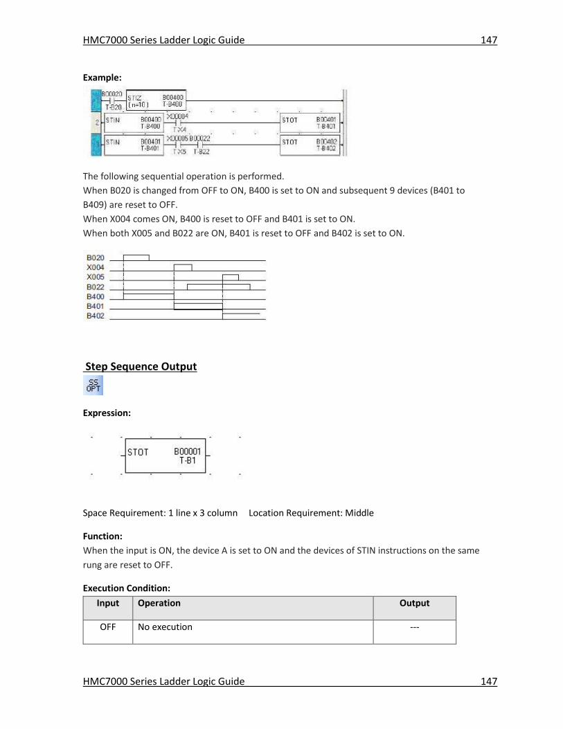
HMC7000 Series Ladder Logic Guide 147
HMC7000 Series Ladder Logic Guide 147
Example:
The following sequential operation is performed.
When B020 is changed from OFF to ON, B400 is set to ON and subsequent 9 devices (B401 to
B409) are reset to OFF.
When X004 comes ON, B400 is reset to OFF and B401 is set to ON.
When both X005 and B022 are ON, B401 is reset to OFF and B402 is set to ON.
Step Sequence Output
Expression:
Space Requirement: 1 line x 3 column Location Requirement: Middle
Function:
When the input is ON, the device A is set to ON and the devices of STIN instructions on the same
rung are reset to OFF.
Execution Condition:
Input Operation Output
OFF No execution ---
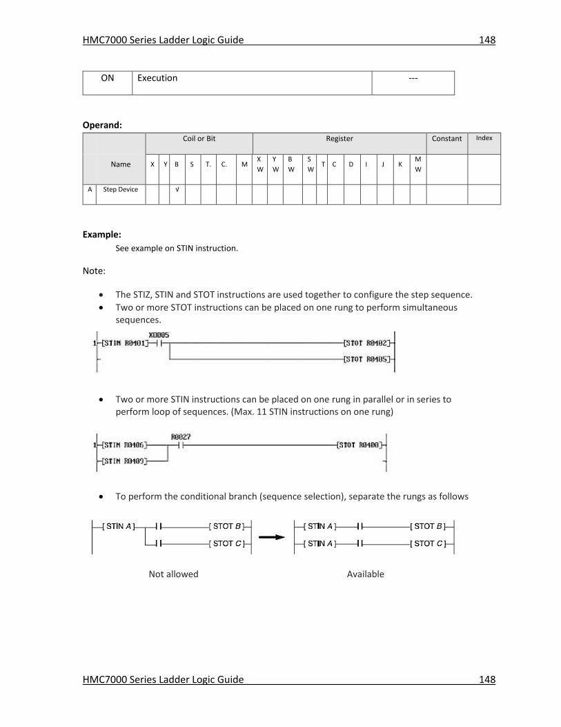
HMC7000 Series Ladder Logic Guide 148
HMC7000 Series Ladder Logic Guide 148
ON Execution ---
Operand:
Coil or Bit Register Constant Index
Name X Y B S T. C. M
X
W
Y
W
B
W
S
W T C D I J K
M
W
A Step Device √
Example:
See example on STIN instruction.
Note:
The STIZ, STIN and STOT instructions are used together to configure the step sequence.
Two or more STOT instructions can be placed on one rung to perform simultaneous sequences.
Two or more STIN instructions can be placed on one rung in parallel or in series to perform loop of sequences. (Max. 11 STIN instructions on one rung)
To perform the conditional branch (sequence selection), separate the rungs as follows
Not allowed Available
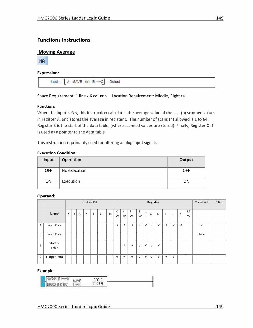
HMC7000 Series Ladder Logic Guide 149
HMC7000 Series Ladder Logic Guide 149
Functions Instructions
Moving Average
Expression:
Space Requirement: 1 line x 6 column Location Requirement: Middle, Right rail
Function:
When the input is ON, this instruction calculates the average value of the last (n) scanned values
in register A, and stores the average in register C. The number of scans (n) allowed is 1 to 64.
Register B is the start of the data table, (where scanned values are stored). Finally, Register C+1
is used as a pointer to the data table.
This instruction is primarily used for filtering analog input signals.
Execution Condition:
Input Operation Output
OFF No execution OFF
ON Execution ON
Operand:
Coil or Bit Register Constant Index
Name X Y B S T. C. M
X
W
Y
W
B
W
S
W T C D I J K
M
W
A Input Data √ √ √ √ √ √ √ √ √ √ √
n Input Data 1-64
B Start of
Table √ √ √ √ √ √
C Output Data √ √ √ √ √ √ √ √ √
Example:
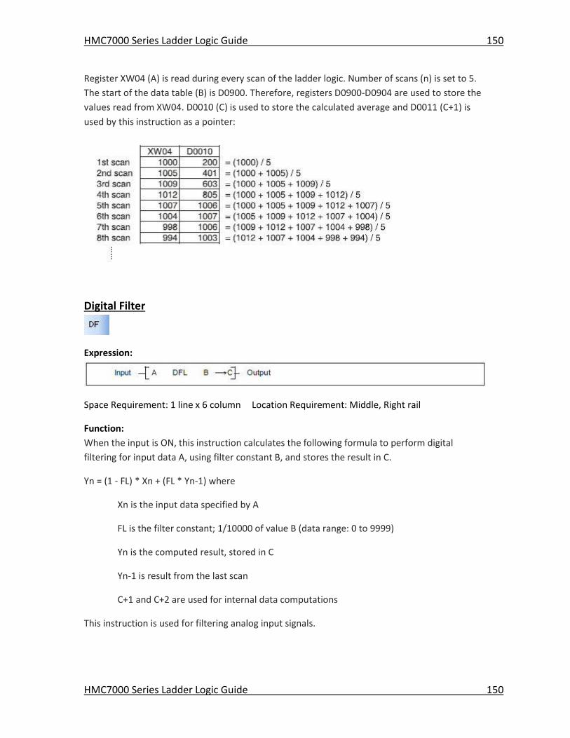
HMC7000 Series Ladder Logic Guide 150
HMC7000 Series Ladder Logic Guide 150
Register XW04 (A) is read during every scan of the ladder logic. Number of scans (n) is set to 5.
The start of the data table (B) is D0900. Therefore, registers D0900-D0904 are used to store the
values read from XW04. D0010 (C) is used to store the calculated average and D0011 (C+1) is
used by this instruction as a pointer:
Digital Filter
Expression:
Space Requirement: 1 line x 6 column Location Requirement: Middle, Right rail
Function:
When the input is ON, this instruction calculates the following formula to perform digital
filtering for input data A, using filter constant B, and stores the result in C.
Yn = (1 - FL) * Xn + (FL * Yn-1) where
Xn is the input data specified by A
FL is the filter constant; 1/10000 of value B (data range: 0 to 9999)
Yn is the computed result, stored in C
Yn-1 is result from the last scan
C+1 and C+2 are used for internal data computations
This instruction is used for filtering analog input signals.
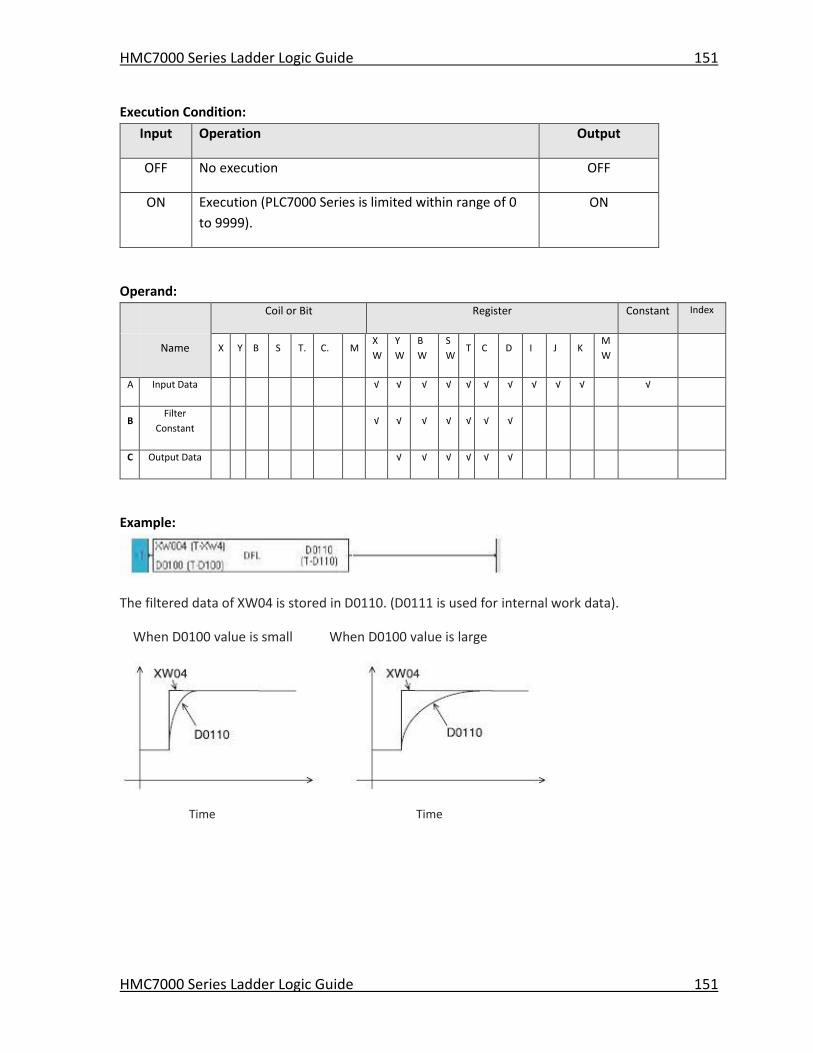
HMC7000 Series Ladder Logic Guide 151
HMC7000 Series Ladder Logic Guide 151
Execution Condition:
Input Operation Output
OFF No execution OFF
ON Execution (PLC7000 Series is limited within range of 0
to 9999).
ON
Operand:
Coil or Bit Register Constant Index
Name X Y B S T. C. M
X
W
Y
W
B
W
S
W T C D I J K
M
W
A Input Data √ √ √ √ √ √ √ √ √ √ √
B Filter
Constant √ √ √ √ √ √ √
C Output Data √ √ √ √ √ √
Example:
The filtered data of XW04 is stored in D0110. (D0111 is used for internal work data).
When D0100 value is small When D0100 value is large
Time Time
HMC7000 Series Ladder Logic Guide 152
HMC7000 Series Ladder Logic Guide 152
PID1
Expression:
Space Requirement: 1 line x 6 column Location Requirement: Middle, Right rail
Function:
This function performs a PID (Proportional, Integral, and Derivative) calculation based upon
fourteen input values. A PID controller is used to monitor some measureable process variable in
a control system and determine how it varies (the “error” value) from a desired setpoint. The
PID controller then adjusts an input to the control system to minimize the error value. The name
is derived from the three basic mathematical functions that are performed in order to derive the
output:
Generally, the Proportional value tracks the present error, the Integral value tracks the
accumulation of past errors, and the Derivative value predicts future error based upon the
current rate of change. MAPware-7000 provides three PID controller instructions that are based
upon three different formulas.
PID1 is based upon the following formula:
--------P--------|------------------I-----------------|---------------------D-------------------|
M= Kp * (e-e-1) + INT ( | Kil | * e + Ir / |Kih| ) + INT [ (|Kdh| / |Kdl|) * (2P-1-P-P-2)]
where:
M= manipulated variable or control value
Kp = the proportional gain constant
e = deviation or error value
e-1 = deviation of prior computation
Kih = the integral gain constant (high limit value)
Kil = the integral gain constant (low limit value)
HMC7000 Series Ladder Logic Guide 153
HMC7000 Series Ladder Logic Guide 153
Kdh = the derivative gain constant (high limit value)
Kdl = the derivative gain constant (low limit value)
Ir = the data remainder of the Integral computation
S = setpoint value
P = Process Variable
P-1 = the Process Variable at the prior computation
P-2 = Process Variable at the second to the last computation
G = gap constant at which the deviation error is considered to be zero (i.e. no
adjustment required). If the calculated error falls within +G, then the deviation is set to
0 (see graph below).
L = limit constant used to limit the deviation error to minimum/maximum value. In other
words, if the calculated deviation error e is greater or less than L, then e is set to L.
Notes:
The INT symbol refers to the integer quotient after division. For example, the integer quotient of INT (18/5) is 3.
The absolute value symbol (ex. |Kil|) is used to indicate that the absolute value is used for the computation.
If KIH=0 the integral calculation is not executed.
If KDL=0 the derivative calculation is not executed.
All ranges are considered to be -32767 to +32768. If the output value M is calculated to be outside of this range, then the lower/upper range limit is used.
Execution Condition:
Input Operation Output
OFF Initialization OFF
ON Execute PID every setting interval ON when
execution
HMC7000 Series Ladder Logic Guide 154
HMC7000 Series Ladder Logic Guide 154
Operand:
Coil or Bit Register Constant Index
Name X Y B S T. C. M
X
W
Y
W
B
W
S
W T C D I J K
M
W
A Top of Input
Data √ √ √ √ √ √ √
B Top of
Parameter √ √ √ √ √ √ √
C Top of
Output Data √ √ √ √ √ √
Input Data
A Process
Variable
P
A+1 Setpoint S
Control Parameters
B Proportional
gain constant
KP
B+1 Integral
coefficient
high
KIH
B+2 Integral
coefficient
low
KIL
B+3 Derivative
coefficient
high
KDH
B+4 Derivative
coefficient
low
KDL
B+5 Gap Constant G
B+6 Limit
Constant
L
Output Data
C Manipulated
Variable
M
C+1 Last deviation
error
e-1
C+2 Last Process
Variable Value
P-
1
C+3 Second to last
Process
Variable value
P-
2
C+4 Remainder
Value
IR
HMC7000 Series Ladder Logic Guide 155
HMC7000 Series Ladder Logic Guide 155
Example:
In this example, the following values are loaded into each Operand register:
Operand A
Offset Parameter Register Value
A Process Variable D12 25
A+1 Setpoint D13 100
Operand B
Offset Parameter Register Value
B Proportional Coefficient D14 1
B+1 Integral Gain Constant High D15 4
B+2 Integral Gain Constant Low D16 10
B+3 Derivative Gain Constant Low D17 20
B+4 Derivative Gain Constant High D18 5
B+5 Gap Constant D19 0
B+6 Limit Constant D20 100
Operand C
Offset Parameter Register Value
C Manipulated Variable D21 0
C+1 Last deviation error D22 78
C+2 Last Present Value D23 22
C+3 2nd to last Present Value D24 20
C+4 Remainder Value D25 0
When the normally open contact B4 is ON, the PID1 calculation is performed based upon the
formula given above and the values entered into the registers. The results are stored in the five
consecutive registers as specified by Operand C.
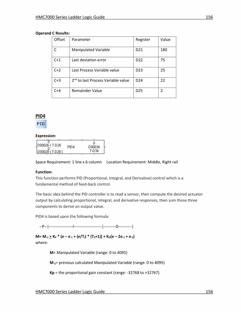
HMC7000 Series Ladder Logic Guide 156
HMC7000 Series Ladder Logic Guide 156
Operand C Results:
Offset Parameter Register Value
C Manipulated Variable D21 180
C+1 Last deviation error D22 75
C+2 Last Process Variable value D23 25
C+3 2nd to last Process Variable value D24 22
C+4 Remainder Value D25 2
PID4
Expression:
Space Requirement: 1 line x 6 column Location Requirement: Middle, Right rail
Function:
This function performs PID (Proportional, Integral, and Derivative) control which is a
fundamental method of feed-back control.
The basic idea behind the PID controller is to read a sensor, then compute the desired actuator
output by calculating proportional, integral, and derivative responses, then sum those three
components to derive an output value.
PID4 is based upon the following formula:
--P--|------------------I---------------------|---------D----------|
M= M-1 + KP * (e – e-1 + (e/TI) * (TS+1)) + KD(e – 2e-1 + e-2)
where:
M= Manipulated Variable (range: 0 to 4095)
M-1= previous calculated Manipulated Variable (range: 0 to 4095)
Kp = the proportional gain constant (range: -32768 to +32767)
HMC7000 Series Ladder Logic Guide 157
HMC7000 Series Ladder Logic Guide 157
e = deviation or error value;
if Action Type = reverse action then e=S-P;
if Action Type = forward action then e=P-S
A = Action Type (range: 0 for forward, 1 for reverse); this determines if the manipulation
value increases/decreases as the present value increases. For example, if you have an
electric heater, you would want the manipulation value to increase as temperature goes
down (i.e. reverse action so e=S-P). On the other hand, if you have a control valve used
to put cold air into a system, you would want the manipulation value to decrease as
temperature goes down (i.e. forward action so e=P-S).
e-1 = deviation of prior computation (range: -32768 to +32767)
e-2 = deviation of second to last computation (range: -32768 to +32767)
TI = integral time value (range: 0 to +32767)
TS = the scan interval (range: 0 to +32767)
KD = the derivative gain constant (range: -32768 to +32767)
S = setpoint value (range: -32768 to +32767)
P = Process Variable (range: -32768 to +32767)
GP = the gap or dead-band value. A dead-band limit causes the PID instruction to only
execute when the error value is less than the dead-band value. The dead band must be
given as a percentage of the setpoint value (i.e. range is 0 to 100). For example, if
GP=10, and S=200, then 10% of 200 is 20, so the dead-band gap is the range of 180-220.
Note:
When the PID instruction is not executed, the manipulation variable (M) is set automatically to 0 or 4095, depending upon:
if S > P then M=4095
if P > S then M=0
Execution Condition:
Input Operation Output
OFF Initialization OFF
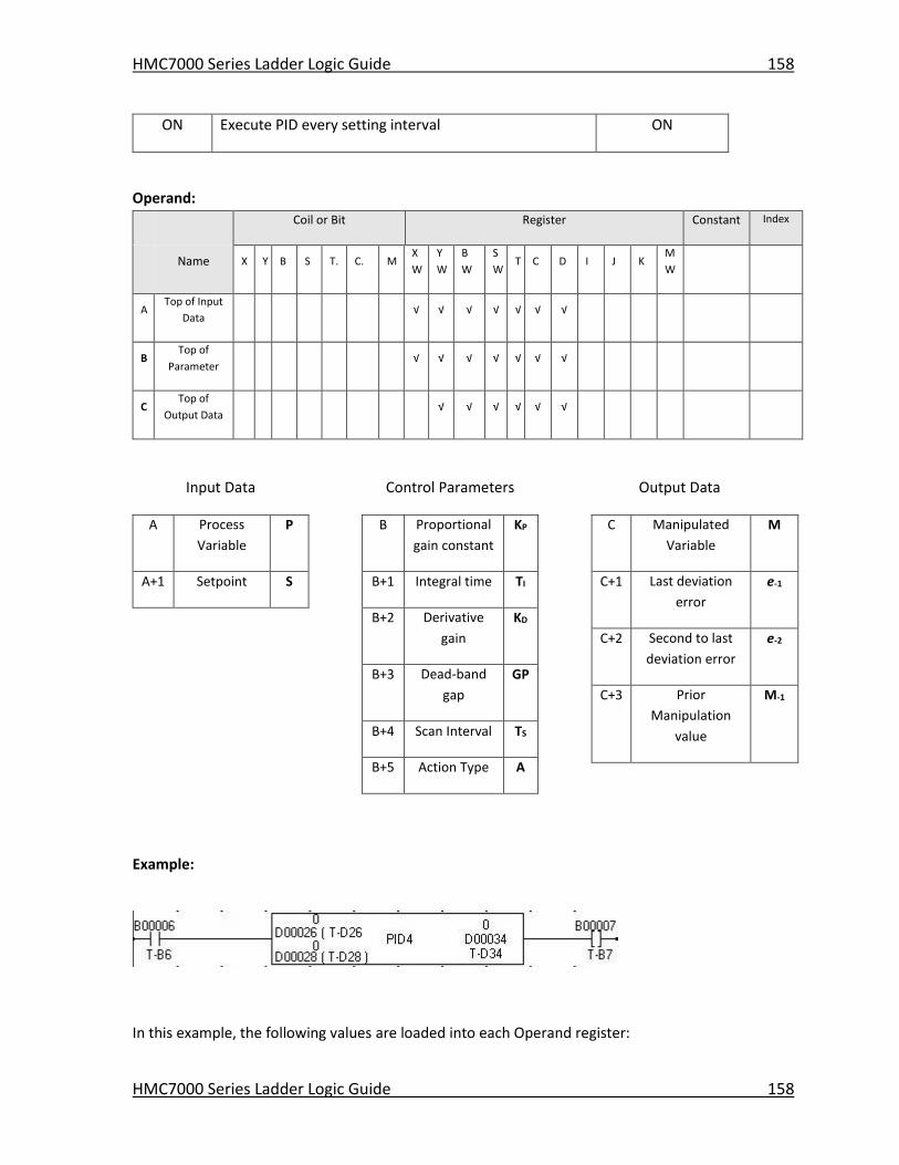
HMC7000 Series Ladder Logic Guide 158
HMC7000 Series Ladder Logic Guide 158
ON Execute PID every setting interval ON
Operand:
Coil or Bit Register Constant Index
Name X Y B S T. C. M
X
W
Y
W
B
W
S
W T C D I J K
M
W
A Top of Input
Data √ √ √ √ √ √ √
B Top of
Parameter √ √ √ √ √ √ √
C Top of
Output Data √ √ √ √ √ √
Input Data
A Process
Variable
P
A+1 Setpoint S
Control Parameters
B Proportional
gain constant
KP
B+1 Integral time TI
B+2 Derivative
gain
KD
B+3 Dead-band
gap
GP
B+4 Scan Interval TS
B+5 Action Type A
Output Data
C Manipulated
Variable
M
C+1 Last deviation
error
e-1
C+2 Second to last
deviation error
e-2
C+3 Prior
Manipulation
value
M-1
Example:
In this example, the following values are loaded into each Operand register:
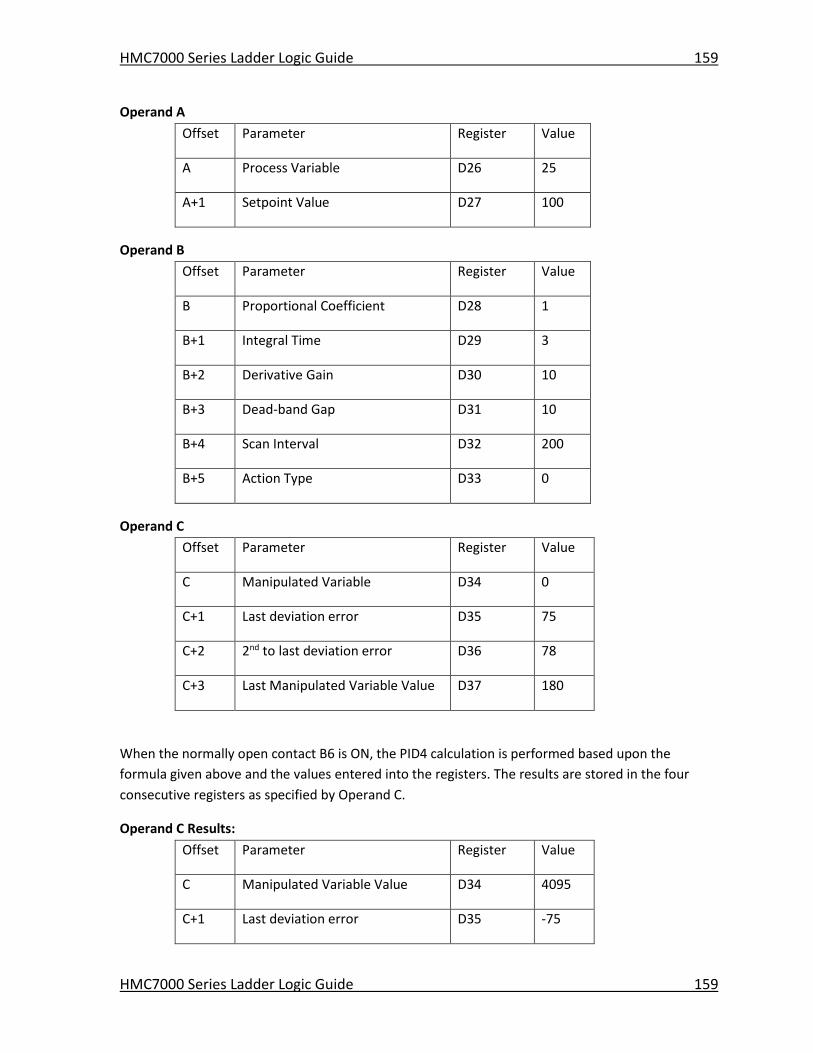
HMC7000 Series Ladder Logic Guide 159
HMC7000 Series Ladder Logic Guide 159
Operand A
Offset Parameter Register Value
A Process Variable D26 25
A+1 Setpoint Value D27 100
Operand B
Offset Parameter Register Value
B Proportional Coefficient D28 1
B+1 Integral Time D29 3
B+2 Derivative Gain D30 10
B+3 Dead-band Gap D31 10
B+4 Scan Interval D32 200
B+5 Action Type D33 0
Operand C
Offset Parameter Register Value
C Manipulated Variable D34 0
C+1 Last deviation error D35 75
C+2 2nd to last deviation error D36 78
C+3 Last Manipulated Variable Value D37 180
When the normally open contact B6 is ON, the PID4 calculation is performed based upon the
formula given above and the values entered into the registers. The results are stored in the four
consecutive registers as specified by Operand C.
Operand C Results:
Offset Parameter Register Value
C Manipulated Variable Value D34 4095
C+1 Last deviation error D35 -75
HMC7000 Series Ladder Logic Guide 160
HMC7000 Series Ladder Logic Guide 160
C+2 2nd to last deviation error D36 75
C+3 Last Manipulated Variable Value D37 0
Upper Limit
Expression:
Space Requirement: 1 line x 6 column Location Requirement: Middle, Right rail
Function:
When the input is ON, this function compares the value in A with the Upper Limit value as set in
B. If the upper limit value is not exceeded, then value in A is placed into C. If upper limit is
exceeded, the upper limit value is placed into C:
If A < B, then C = A.
If A > B, then C = B.
Execution Condition:
Input Operation Output
OFF No execution OFF
ON Execution: not limited (A<B) OFF
Execution: limited (A>B) ON
Operand:
Coil or Bit Register Constant Index
Name X Y B S T. C. M
X
W
Y
W
B
W
S
W T C D I J K
M
W
A Operation
Data √ √ √ √ √ √ √ √ √ √ √ √
B Upper Limit √ √ √ √ √ √ √ √ √ √ √ √
C Destination √ √ √ √ √ √ √ √ √ √
HMC7000 Series Ladder Logic Guide 161
HMC7000 Series Ladder Logic Guide 161
Example:
When B030 is ON, the upper limit operation is executed for the data of BW018 by the data of
D1200, and the result is stored in BW021.
When BW018 is 3000 and D1200 is 4000, 3000 is stored in BW021 and B0040 is OFF.
When BW018 is 4500 and D1200 is 4000, the limit value 4000 is stored in BW021 and B0040 is
ON.
Note:
This instruction deals with the data as signed integer (-32768 to 32767).
Lower Limit
Expression:
Space Requirement: 1 line x 6 column Location Requirement: Middle, Right rail
Function:
When the input is ON, this function compares the value in A with the Lower Limit value as set in
B. If the lower limit value is not exceeded, then value in A is placed into C. If lower limit is
exceeded, the lower limit value is placed into C:
If A > B, then C = A.
If A < B, then C = B.
HMC7000 Series Ladder Logic Guide 162
HMC7000 Series Ladder Logic Guide 162
Execution Condition:
Input Operation Output
OFF No execution OFF
ON Execution: not limited (A>B) OFF
Execution: limited (A<B) ON
Operand:
Coil or Bit Register Constant Index
Name X Y B S T. C. M
X
W
Y
W
B
W
S
W T C D I J K
M
W
A Operation
Data √ √ √ √ √ √ √ √ √ √ √ √
B Lower Limit √ √ √ √ √ √ √ √ √ √ √ √
C Destination √ √ √ √ √ √ √ √ √ √
Example:
When B031 is ON, the lower limit operation is executed for the data of BW019 by the data of
D1220, and the result is stored in BW022.
When BW019 is -1000 and D1220 is -1800, -1000 is stored in BW022 and B0041 is OFF.
When BW019 is 800 and D1220 is 1200, the limit value 1200 is stored in BW022 and B0041 is
ON.
Note:
This instruction deals with the data as signed integer (-32768 to 32767).
HMC7000 Series Ladder Logic Guide 163
HMC7000 Series Ladder Logic Guide 163
Maximum Value
Expression:
Space Requirement: 1 line x 5 column Location Requirement: Middle, Right rail
Function:
When the input is ON, this instruction searches for the maximum value from the table of size n
words starting with A, and stores the maximum value in B and the pointer indicating the
position of the maximum value in B+1. The allowable range of the table size n is 1 to 64.
Execution Condition:
Input Operation Output
OFF No execution OFF
ON Execution ON
Operand:
Coil or Bit Register Constant Index
Name X Y B S T. C. M
X
W
Y
W
B
W
S
W T C D I J K
M
W
A Start of table √ √ √ √ √ √ √ √ √ √
N Table size 1-64
B Result √ √ √ √ √ √ √ √ √
Example:
When B010 is ON, the maximum value is found from the register table D0200 to D0209 (10
words), and the maximum value is stored in D0500 and the pointer is stored in D0501.
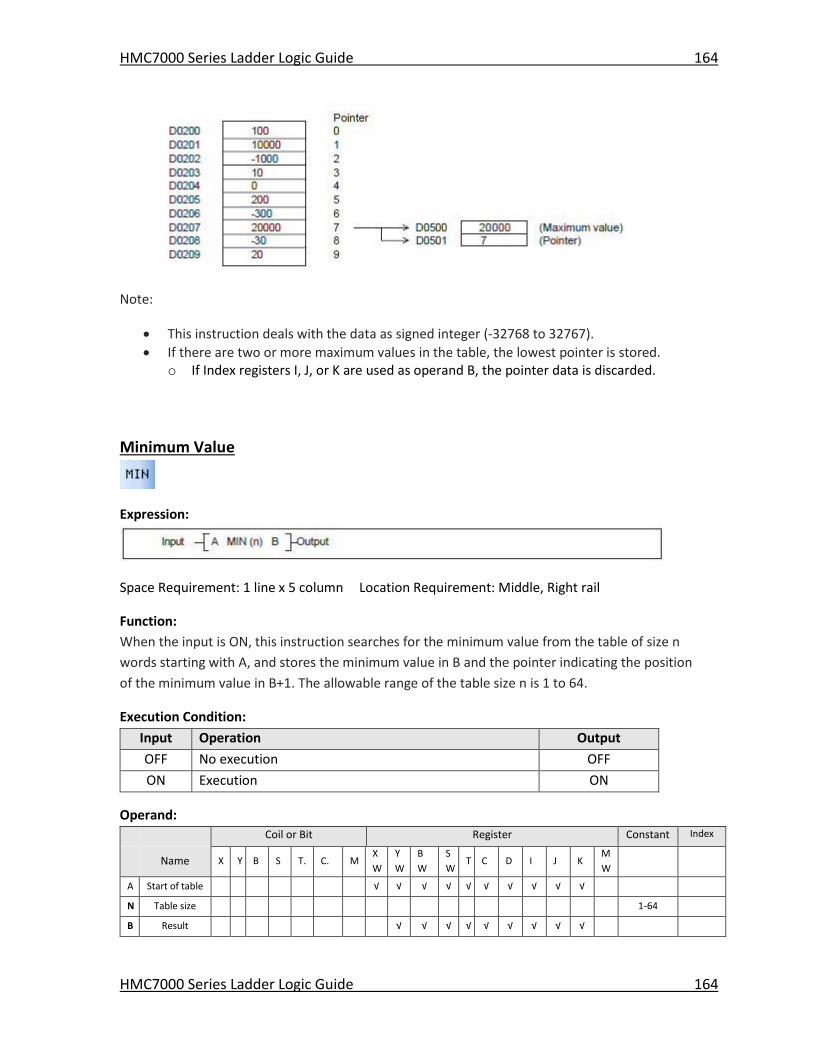
HMC7000 Series Ladder Logic Guide 164
HMC7000 Series Ladder Logic Guide 164
Note:
This instruction deals with the data as signed integer (-32768 to 32767).
If there are two or more maximum values in the table, the lowest pointer is stored. o If Index registers I, J, or K are used as operand B, the pointer data is discarded.
Minimum Value
Expression:
Space Requirement: 1 line x 5 column Location Requirement: Middle, Right rail
Function:
When the input is ON, this instruction searches for the minimum value from the table of size n
words starting with A, and stores the minimum value in B and the pointer indicating the position
of the minimum value in B+1. The allowable range of the table size n is 1 to 64.
Execution Condition:
Input Operation Output
OFF No execution OFF
ON Execution ON
Operand:
Coil or Bit Register Constant Index
Name X Y B S T. C. M
X
W
Y
W
B
W
S
W T C D I J K
M
W
A Start of table √ √ √ √ √ √ √ √ √ √
N Table size 1-64
B Result √ √ √ √ √ √ √ √ √
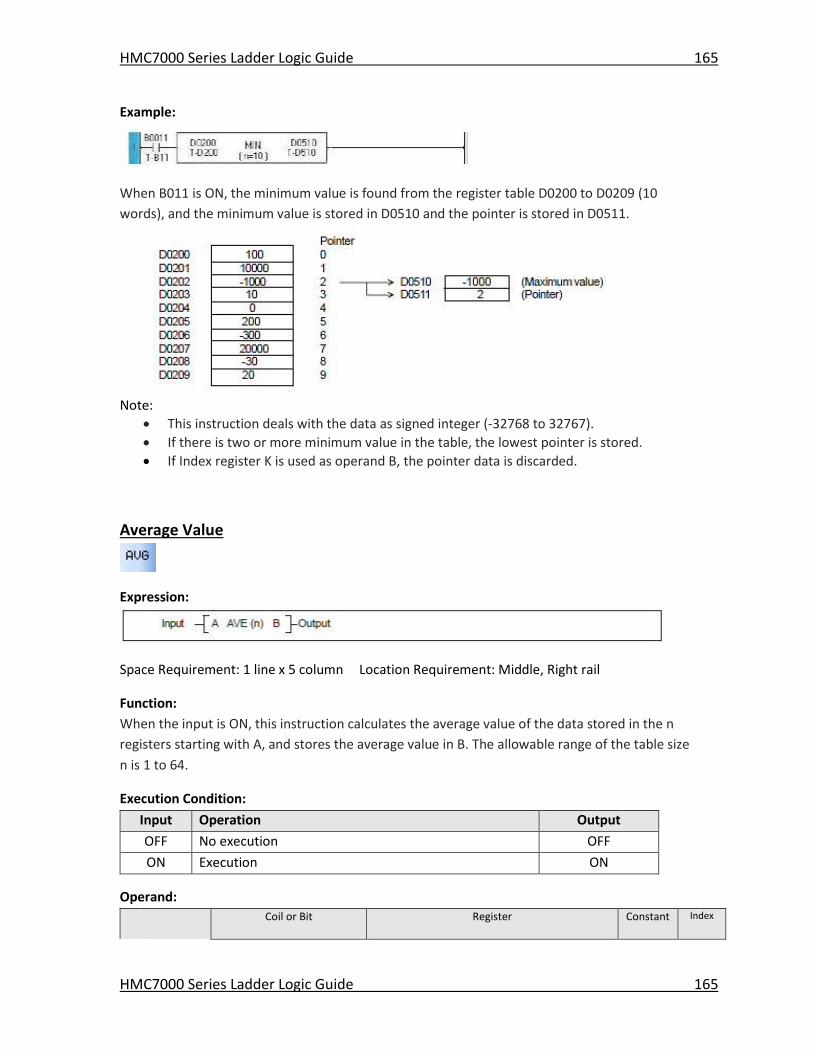
HMC7000 Series Ladder Logic Guide 165
HMC7000 Series Ladder Logic Guide 165
Example:
When B011 is ON, the minimum value is found from the register table D0200 to D0209 (10
words), and the minimum value is stored in D0510 and the pointer is stored in D0511.
Note:
This instruction deals with the data as signed integer (-32768 to 32767).
If there is two or more minimum value in the table, the lowest pointer is stored.
If Index register K is used as operand B, the pointer data is discarded.
Average Value
Expression:
Space Requirement: 1 line x 5 column Location Requirement: Middle, Right rail
Function:
When the input is ON, this instruction calculates the average value of the data stored in the n
registers starting with A, and stores the average value in B. The allowable range of the table size
n is 1 to 64.
Execution Condition:
Input Operation Output
OFF No execution OFF
ON Execution ON
Operand:
Coil or Bit Register Constant Index
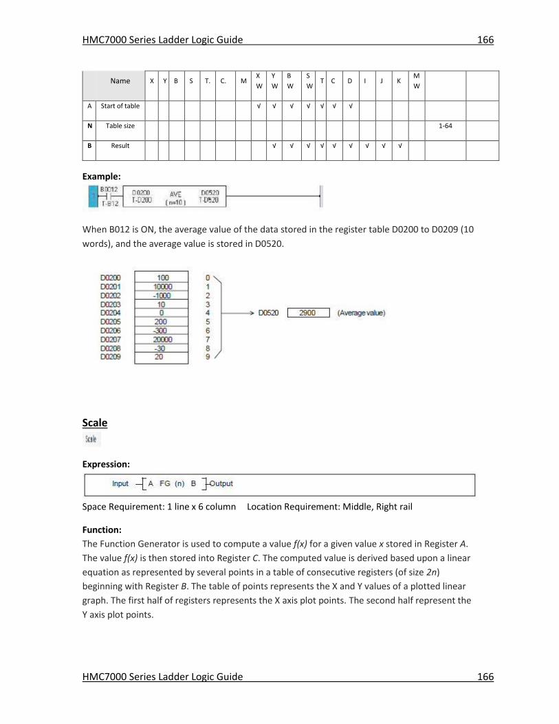
HMC7000 Series Ladder Logic Guide 166
HMC7000 Series Ladder Logic Guide 166
Name X Y B S T. C. M
X
W
Y
W
B
W
S
W T C D I J K
M
W
A Start of table √ √ √ √ √ √ √
N Table size 1-64
B Result √ √ √ √ √ √ √ √ √
Example:
When B012 is ON, the average value of the data stored in the register table D0200 to D0209 (10
words), and the average value is stored in D0520.
Scale
Expression:
Space Requirement: 1 line x 6 column Location Requirement: Middle, Right rail
Function:
The Function Generator is used to compute a value f(x) for a given value x stored in Register A.
The value f(x) is then stored into Register C. The computed value is derived based upon a linear
equation as represented by several points in a table of consecutive registers (of size 2n)
beginning with Register B. The table of points represents the X and Y values of a plotted linear
graph. The first half of registers represents the X axis plot points. The second half represent the
Y axis plot points.
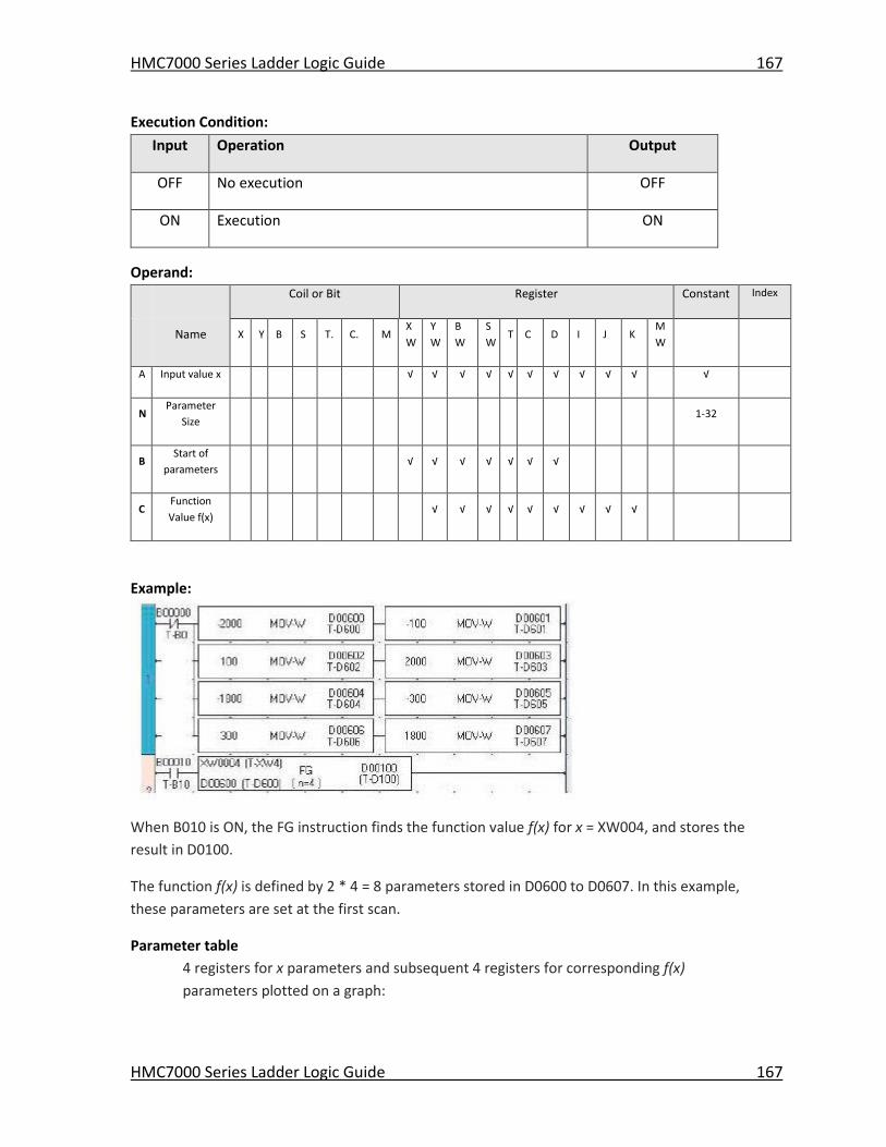
HMC7000 Series Ladder Logic Guide 167
HMC7000 Series Ladder Logic Guide 167
Execution Condition:
Input Operation Output
OFF No execution OFF
ON Execution ON
Operand:
Coil or Bit Register Constant Index
Name X Y B S T. C. M
X
W
Y
W
B
W
S
W T C D I J K
M
W
A Input value x √ √ √ √ √ √ √ √ √ √ √
N Parameter
Size 1-32
B Start of
parameters √ √ √ √ √ √ √
C Function
Value f(x) √ √ √ √ √ √ √ √ √
Example:
When B010 is ON, the FG instruction finds the function value f(x) for x = XW004, and stores the
result in D0100.
The function f(x) is defined by 2 * 4 = 8 parameters stored in D0600 to D0607. In this example,
these parameters are set at the first scan.
Parameter table
4 registers for x parameters and subsequent 4 registers for corresponding f(x)
parameters plotted on a graph:
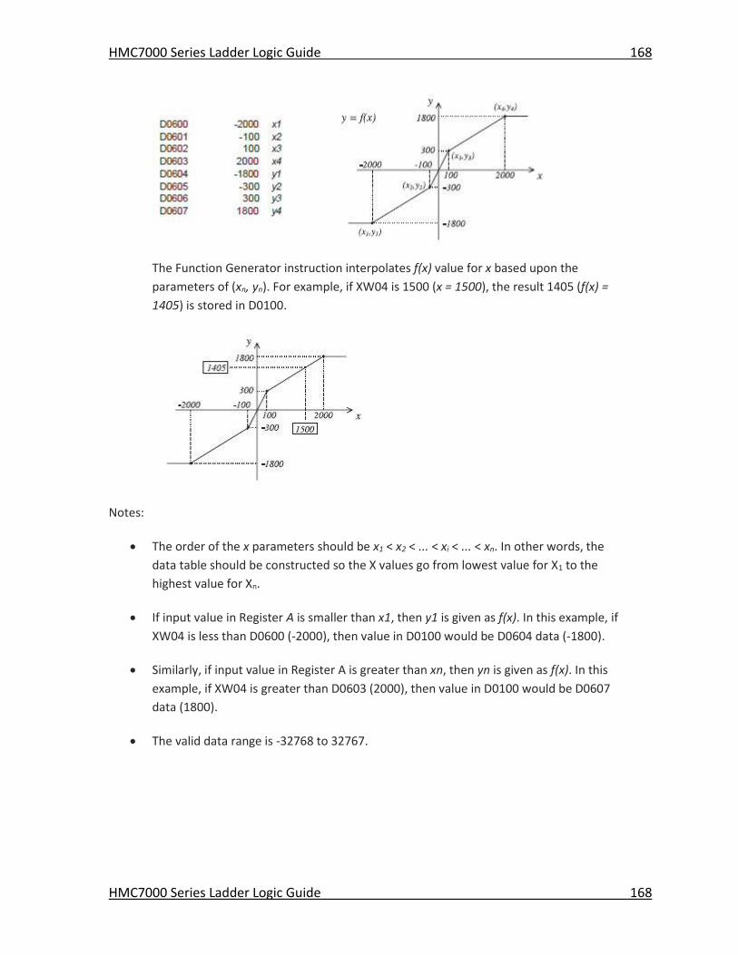
HMC7000 Series Ladder Logic Guide 168
HMC7000 Series Ladder Logic Guide 168
The Function Generator instruction interpolates f(x) value for x based upon the
parameters of (xn, yn). For example, if XW04 is 1500 (x = 1500), the result 1405 (f(x) =
1405) is stored in D0100.
Notes:
The order of the x parameters should be x1 < x2 < ... < xi < ... < xn. In other words, the
data table should be constructed so the X values go from lowest value for X1 to the
highest value for Xn.
If input value in Register A is smaller than x1, then y1 is given as f(x). In this example, if
XW04 is less than D0600 (-2000), then value in D0100 would be D0604 data (-1800).
Similarly, if input value in Register A is greater than xn, then yn is given as f(x). In this
example, if XW04 is greater than D0603 (2000), then value in D0100 would be D0607
data (1800).
The valid data range is -32768 to 32767.
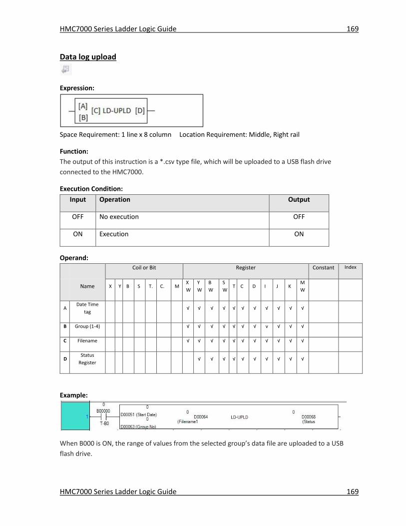
HMC7000 Series Ladder Logic Guide 169
HMC7000 Series Ladder Logic Guide 169
Data log upload
Expression:
Space Requirement: 1 line x 8 column Location Requirement: Middle, Right rail
Function:
The output of this instruction is a *.csv type file, which will be uploaded to a USB flash drive
connected to the HMC7000.
Execution Condition:
Input Operation Output
OFF No execution OFF
ON Execution ON
Operand:
Coil or Bit Register Constant Index
Name X Y B S T. C. M
X
W
Y
W
B
W
S
W T C D I J K
M
W
A Date Time
tag √ √ √ √ √ √ √ √ √ √ √
B Group (1-4) √ √ √ √ √ √ √ v √ √ √
C Filename √ √ √ √ √ √ √ √ √ √ √
D Status
Register √ √ √ √ √ √ √ √ √ √
Example:
When B000 is ON, the range of values from the selected group’s data file are uploaded to a USB
flash drive.
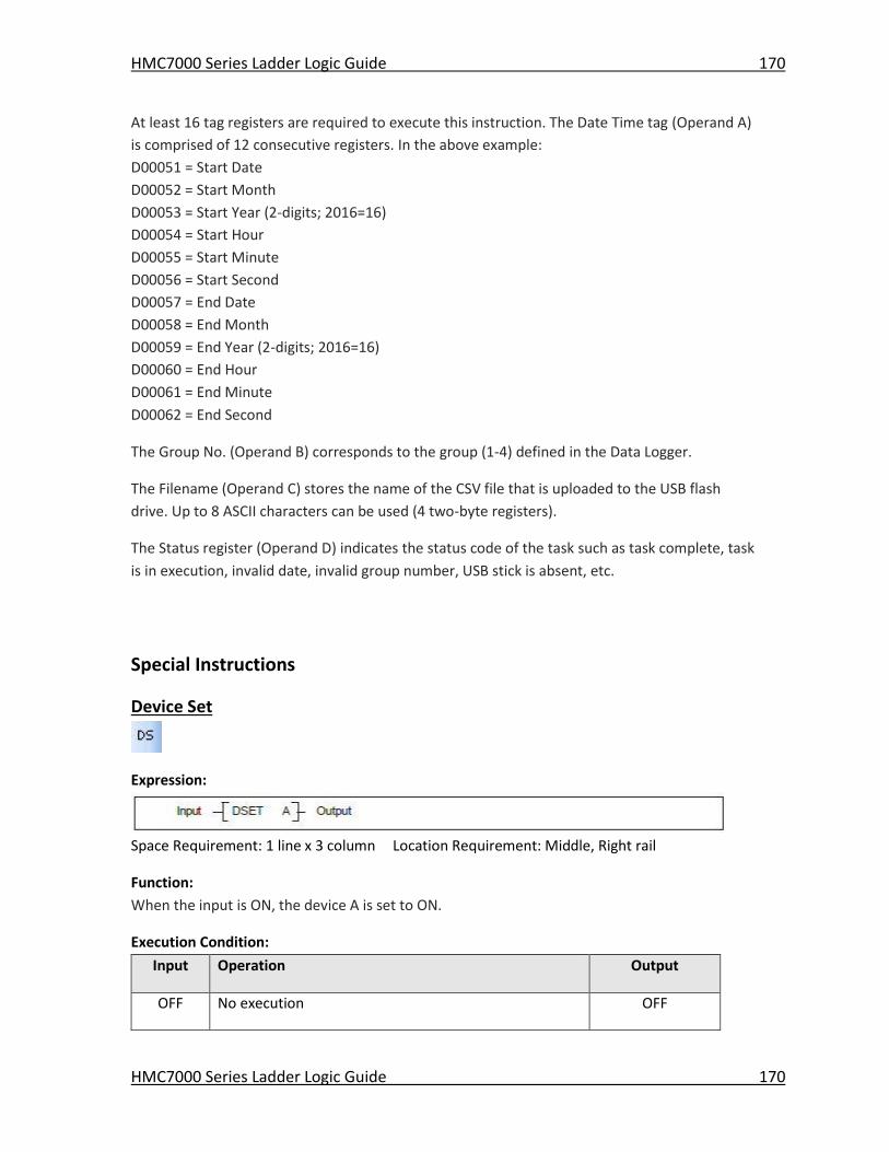
HMC7000 Series Ladder Logic Guide 170
HMC7000 Series Ladder Logic Guide 170
At least 16 tag registers are required to execute this instruction. The Date Time tag (Operand A)
is comprised of 12 consecutive registers. In the above example:
D00051 = Start Date
D00052 = Start Month
D00053 = Start Year (2-digits; 2016=16)
D00054 = Start Hour
D00055 = Start Minute
D00056 = Start Second
D00057 = End Date
D00058 = End Month
D00059 = End Year (2-digits; 2016=16)
D00060 = End Hour
D00061 = End Minute
D00062 = End Second
The Group No. (Operand B) corresponds to the group (1-4) defined in the Data Logger.
The Filename (Operand C) stores the name of the CSV file that is uploaded to the USB flash
drive. Up to 8 ASCII characters can be used (4 two-byte registers).
The Status register (Operand D) indicates the status code of the task such as task complete, task
is in execution, invalid date, invalid group number, USB stick is absent, etc.
Special Instructions
Device Set
Expression:
Space Requirement: 1 line x 3 column Location Requirement: Middle, Right rail
Function:
When the input is ON, the device A is set to ON.
Execution Condition:
Input Operation Output
OFF No execution OFF
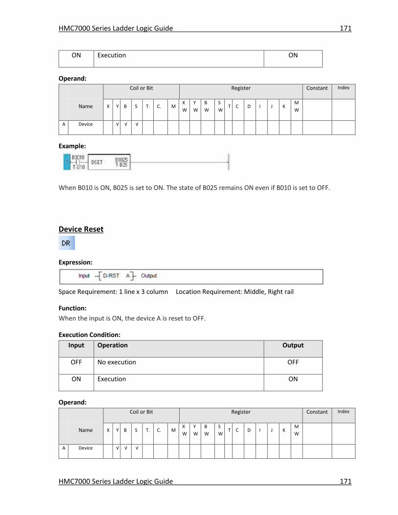
HMC7000 Series Ladder Logic Guide 171
HMC7000 Series Ladder Logic Guide 171
ON Execution ON
Operand:
Coil or Bit Register Constant Index
Name X Y B S T. C. M
X
W
Y
W
B
W
S
W T C D I J K
M
W
A Device √ √ √
Example:
When B010 is ON, B025 is set to ON. The state of B025 remains ON even if B010 is set to OFF.
Device Reset
Expression:
Space Requirement: 1 line x 3 column Location Requirement: Middle, Right rail
Function:
When the input is ON, the device A is reset to OFF.
Execution Condition:
Input Operation Output
OFF No execution OFF
ON Execution ON
Operand:
Coil or Bit Register Constant Index
Name X Y B S T. C. M
X
W
Y
W
B
W
S
W T C D I J K
M
W
A Device √ √ √
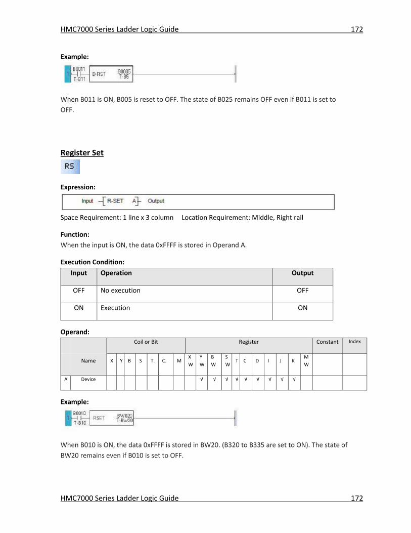
HMC7000 Series Ladder Logic Guide 172
HMC7000 Series Ladder Logic Guide 172
Example:
When B011 is ON, B005 is reset to OFF. The state of B025 remains OFF even if B011 is set to
OFF.
Register Set
Expression:
Space Requirement: 1 line x 3 column Location Requirement: Middle, Right rail
Function:
When the input is ON, the data 0xFFFF is stored in Operand A.
Execution Condition:
Input Operation Output
OFF No execution OFF
ON Execution ON
Operand:
Coil or Bit Register Constant Index
Name X Y B S T. C. M
X
W
Y
W
B
W
S
W T C D I J K
M
W
A Device √ √ √ √ √ √ √ √ √
Example:
When B010 is ON, the data 0xFFFF is stored in BW20. (B320 to B335 are set to ON). The state of
BW20 remains even if B010 is set to OFF.
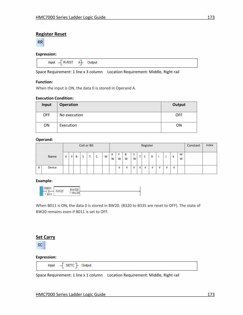
HMC7000 Series Ladder Logic Guide 173
HMC7000 Series Ladder Logic Guide 173
Register Reset
Expression:
Space Requirement: 1 line x 3 column Location Requirement: Middle, Right rail
Function:
When the input is ON, the data 0 is stored in Operand A.
Execution Condition:
Input Operation Output
OFF No execution OFF
ON Execution ON
Operand:
Coil or Bit Register Constant Index
Name X Y B S T. C. M
X
W
Y
W
B
W
S
W T C D I J K
M
W
A Device √ √ √ √ √ √ √ √ √
Example:
When B011 is ON, the data 0 is stored in BW20. (B320 to B335 are reset to OFF). The state of
BW20 remains even if B011 is set to OFF.
Set Carry
Expression:
Space Requirement: 1 line x 1 column Location Requirement: Middle, Right rail
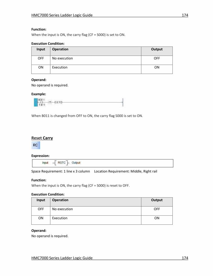
HMC7000 Series Ladder Logic Guide 174
HMC7000 Series Ladder Logic Guide 174
Function:
When the input is ON, the carry flag (CF = S000) is set to ON.
Execution Condition:
Input Operation Output
OFF No execution OFF
ON Execution ON
Operand:
No operand is required.
Example:
When B011 is changed from OFF to ON, the carry flag S000 is set to ON.
Reset Carry
Expression:
Space Requirement: 1 line x 3 column Location Requirement: Middle, Right rail
Function:
When the input is ON, the carry flag (CF = S000) is reset to OFF.
Execution Condition:
Input Operation Output
OFF No execution OFF
ON Execution ON
Operand:
No operand is required.
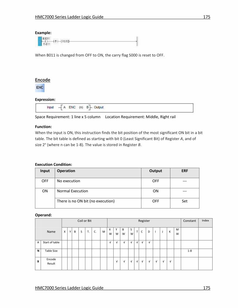
HMC7000 Series Ladder Logic Guide 175
HMC7000 Series Ladder Logic Guide 175
Example:
When B011 is changed from OFF to ON, the carry flag S000 is reset to OFF.
Encode
Expression:
Space Requirement: 1 line x 5 column Location Requirement: Middle, Right rail
Function:
When the input is ON, this instruction finds the bit position of the most significant ON bit in a bit
table. The bit table is defined as starting with bit 0 (Least Significant Bit) of Register A, and of
size 2n (where n can be 1-8). The value is stored in Register B.
Execution Condition:
Input Operation Output ERF
OFF No execution OFF ---
ON Normal Execution ON ---
There is no ON bit (no execution) OFF Set
Operand:
Coil or Bit Register Constant Index
Name X Y B S T. C. M
X
W
Y
W
B
W
S
W T C D I J K
M
W
A Start of table √ √ √ √ √ √ √
N Table Size 1-8
B Encode
Result √ √ √ √ √ √ √ √ √
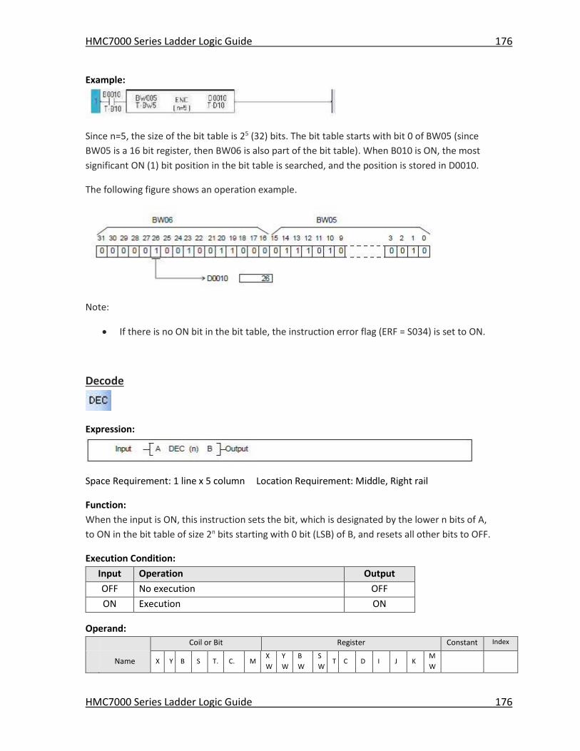
HMC7000 Series Ladder Logic Guide 176
HMC7000 Series Ladder Logic Guide 176
Example:
Since n=5, the size of the bit table is 25 (32) bits. The bit table starts with bit 0 of BW05 (since
BW05 is a 16 bit register, then BW06 is also part of the bit table). When B010 is ON, the most
significant ON (1) bit position in the bit table is searched, and the position is stored in D0010.
The following figure shows an operation example.
Note:
If there is no ON bit in the bit table, the instruction error flag (ERF = S034) is set to ON.
Decode
Expression:
Space Requirement: 1 line x 5 column Location Requirement: Middle, Right rail
Function:
When the input is ON, this instruction sets the bit, which is designated by the lower n bits of A,
to ON in the bit table of size 2n bits starting with 0 bit (LSB) of B, and resets all other bits to OFF.
Execution Condition:
Input Operation Output
OFF No execution OFF
ON Execution ON
Operand:
Coil or Bit Register Constant Index
Name X Y B S T. C. M
X
W
Y
W
B
W
S
W T C D I J K
M
W
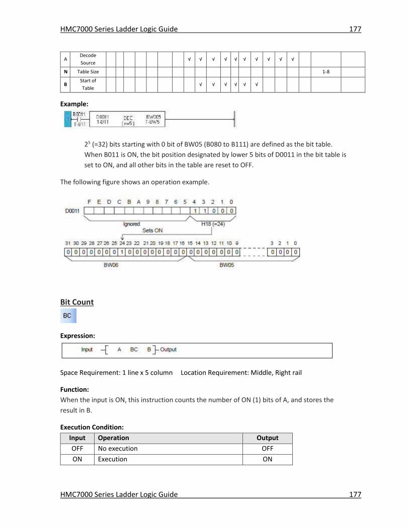
HMC7000 Series Ladder Logic Guide 177
HMC7000 Series Ladder Logic Guide 177
A Decode
Source √ √ √ √ √ √ √ √ √ √
N Table Size 1-8
B Start of
Table √ √ √ √ √ √
Example:
25 (=32) bits starting with 0 bit of BW05 (B080 to B111) are defined as the bit table.
When B011 is ON, the bit position designated by lower 5 bits of D0011 in the bit table is
set to ON, and all other bits in the table are reset to OFF.
The following figure shows an operation example.
Bit Count
Expression:
Space Requirement: 1 line x 5 column Location Requirement: Middle, Right rail
Function:
When the input is ON, this instruction counts the number of ON (1) bits of A, and stores the
result in B.
Execution Condition:
Input Operation Output
OFF No execution OFF
ON Execution ON
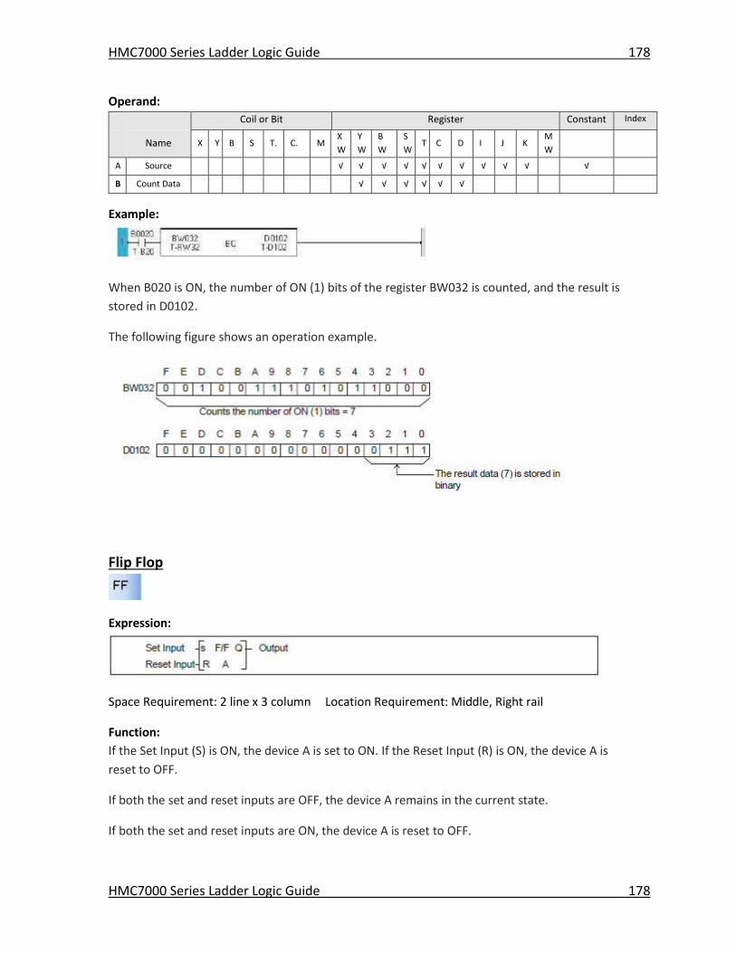
HMC7000 Series Ladder Logic Guide 178
HMC7000 Series Ladder Logic Guide 178
Operand:
Coil or Bit Register Constant Index
Name X Y B S T. C. M
X
W
Y
W
B
W
S
W T C D I J K
M
W
A Source √ √ √ √ √ √ √ √ √ √ √
B Count Data √ √ √ √ √ √
Example:
When B020 is ON, the number of ON (1) bits of the register BW032 is counted, and the result is
stored in D0102.
The following figure shows an operation example.
Flip Flop
Expression:
Space Requirement: 2 line x 3 column Location Requirement: Middle, Right rail
Function:
If the Set Input (S) is ON, the device A is set to ON. If the Reset Input (R) is ON, the device A is
reset to OFF.
If both the set and reset inputs are OFF, the device A remains in the current state.
If both the set and reset inputs are ON, the device A is reset to OFF.
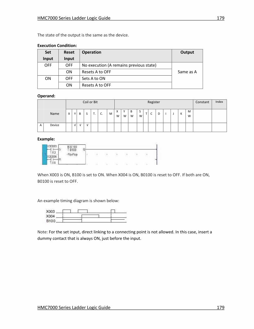
HMC7000 Series Ladder Logic Guide 179
HMC7000 Series Ladder Logic Guide 179
The state of the output is the same as the device.
Execution Condition:
Set
Input
Reset
Input
Operation Output
OFF OFF No execution (A remains previous state)
ON Resets A to OFF Same as A
ON OFF Sets A to ON
ON Resets A to OFF
Operand:
Coil or Bit Register Constant Index
Name X Y B S T. C. M
X
W
Y
W
B
W
S
W T C D I J K
M
W
A Device √ √ √
Example:
When X003 is ON, B100 is set to ON. When X004 is ON, B0100 is reset to OFF. If both are ON,
B0100 is reset to OFF.
An example timing diagram is shown below:
Note: For the set input, direct linking to a connecting point is not allowed. In this case, insert a
dummy contact that is always ON, just before the input.
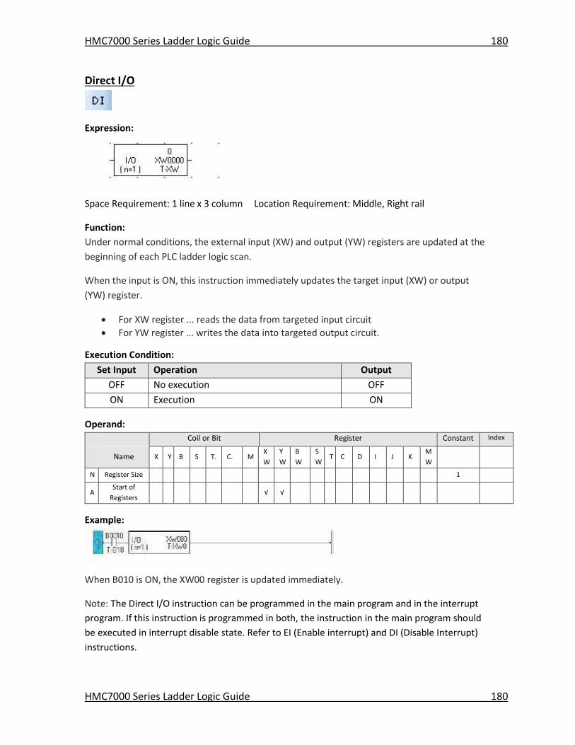
HMC7000 Series Ladder Logic Guide 180
HMC7000 Series Ladder Logic Guide 180
Direct I/O
Expression:
Space Requirement: 1 line x 3 column Location Requirement: Middle, Right rail
Function:
Under normal conditions, the external input (XW) and output (YW) registers are updated at the
beginning of each PLC ladder logic scan.
When the input is ON, this instruction immediately updates the target input (XW) or output
(YW) register.
For XW register ... reads the data from targeted input circuit
For YW register ... writes the data into targeted output circuit.
Execution Condition:
Set Input Operation Output
OFF No execution OFF
ON Execution ON
Operand:
Coil or Bit Register Constant Index
Name X Y B S T. C. M
X
W
Y
W
B
W
S
W T C D I J K
M
W
N Register Size 1
A Start of
Registers √ √
Example:
When B010 is ON, the XW00 register is updated immediately.
Note: The Direct I/O instruction can be programmed in the main program and in the interrupt
program. If this instruction is programmed in both, the instruction in the main program should
be executed in interrupt disable state. Refer to EI (Enable interrupt) and DI (Disable Interrupt)
instructions.
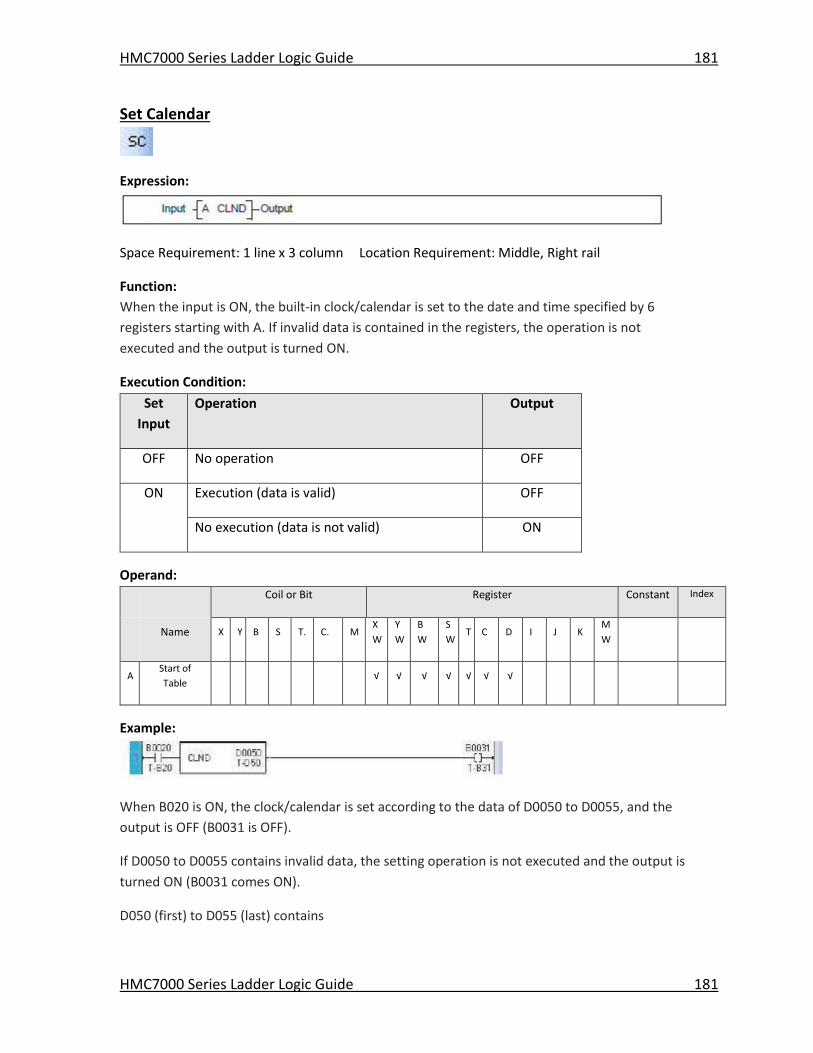
HMC7000 Series Ladder Logic Guide 181
HMC7000 Series Ladder Logic Guide 181
Set Calendar
Expression:
Space Requirement: 1 line x 3 column Location Requirement: Middle, Right rail
Function:
When the input is ON, the built-in clock/calendar is set to the date and time specified by 6
registers starting with A. If invalid data is contained in the registers, the operation is not
executed and the output is turned ON.
Execution Condition:
Set
Input
Operation Output
OFF No operation OFF
ON Execution (data is valid) OFF
No execution (data is not valid) ON
Operand:
Coil or Bit Register Constant Index
Name X Y B S T. C. M
X
W
Y
W
B
W
S
W T C D I J K
M
W
A Start of
Table √ √ √ √ √ √ √
Example:
When B020 is ON, the clock/calendar is set according to the data of D0050 to D0055, and the
output is OFF (B0031 is OFF).
If D0050 to D0055 contains invalid data, the setting operation is not executed and the output is
turned ON (B0031 comes ON).
D050 (first) to D055 (last) contains
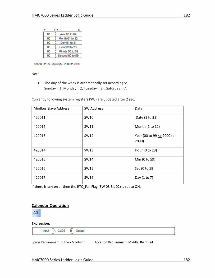
HMC7000 Series Ladder Logic Guide 182
HMC7000 Series Ladder Logic Guide 182
Note:
The day of the week is automatically set accordingly:
Sunday = 1, Monday = 2, Tuesday = 3 ...Saturday = 7.
Currently following system registers (SW) are updated after 2 sec:
Modbus Slave Address SW Address Data
420011 SW10 Date (1 to 31)
420012 SW11 Month (1 to 12)
420013 SW12 Year (00 to 99 <> 2000 to
2099)
420014 SW13 Hour (0 to 23)
420015 SW14 Min (0 to 59)
420016 SW15 Sec (0 to 59)
420017 SW16 Day (1 to 7)
If there is any error then the RTC_Fail Flag (SW 03 Bit 02) is set to ON.
Calendar Operation
Expression:
Space Requirement: 1 line x 5 column Location Requirement: Middle, Right rail
HMC7000 Series Ladder Logic Guide 183
HMC7000 Series Ladder Logic Guide 183
Function:
Use this function to determine how many days, hours, minutes, and seconds have passed between the
date/time entered into Operand A and the current time in the RTC of the HMC7000. The result is stored
into Operand B.
When the input is ON, this instruction subtracts the date and time stored in 6 registers starting with A
from the current date and time, and stores the result in 6 registers starting with B. If an invalid data is
contained in the registers, the operation is not executed and the output is turned ON.
Execution Condition:
Set
Input
Operation Output
OFF No operation OFF
ON Execution (data is valid) OFF
No execution (data is not valid) ON
Operand:
Coil or Bit Register Constant Index
Name X Y B S T. C. M
X
W
Y
W
B
W
S
W T C D I J K
M
W
A Subtrahend √ √ √ √ √ √ √
B Result √ √ √ √ √ √
Example:
In this example, the current date/time in the HMC7000 unit is 5pm on January 15th, 1998. The
date/time stored in registers D0050-55 is 3:30pm on October 10th, 1997. How much time has
transpired between these dates? (see Answer below)
When B020 is ON, the date and time data recorded in D0050 to D0055 are subtracted from the
current date and time of the internal RTC. The result is stored in D0100 to D0105. During normal
operation, the output (B0035) is OFF. If D0050 to D0055 contain any invalid data, then operation
is not executed and the output (B0035) is turned ON.
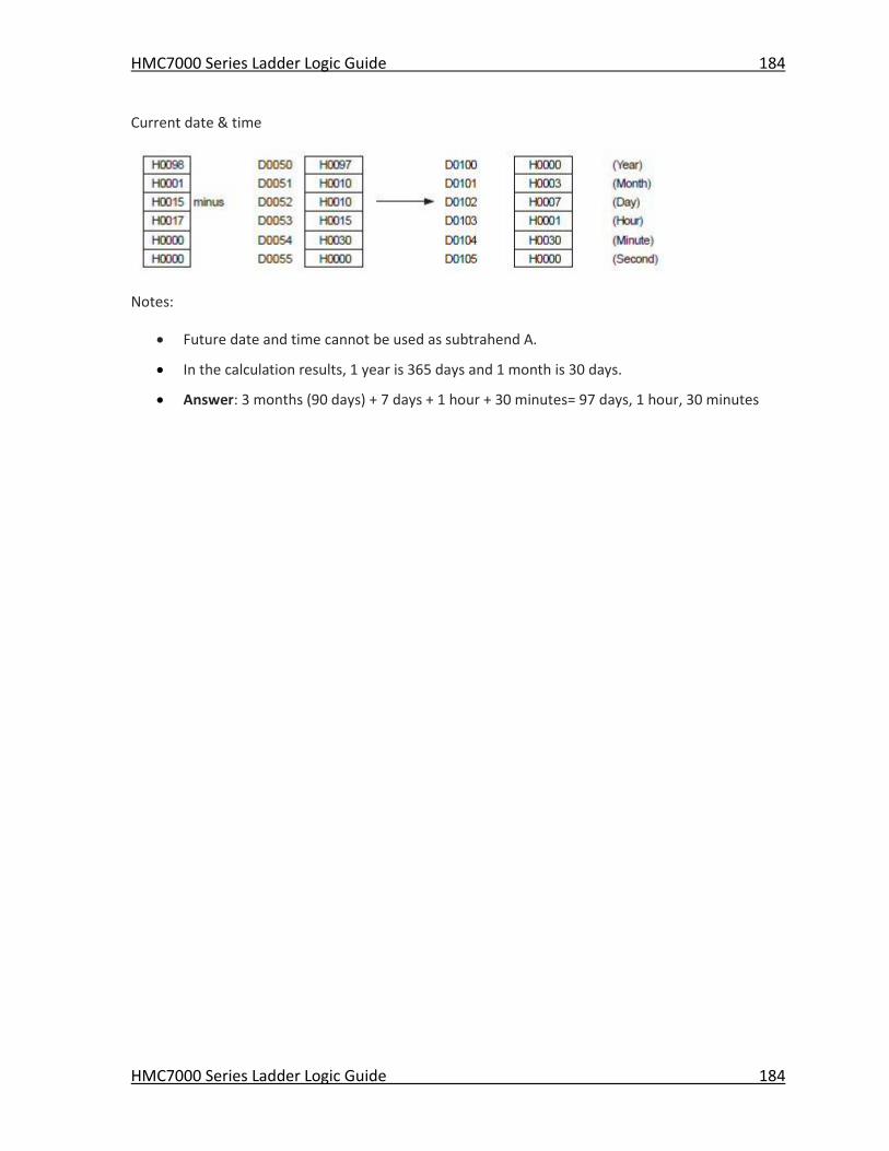
HMC7000 Series Ladder Logic Guide 184
HMC7000 Series Ladder Logic Guide 184
Current date & time
Notes:
Future date and time cannot be used as subtrahend A.
In the calculation results, 1 year is 365 days and 1 month is 30 days.
Answer: 3 months (90 days) + 7 days + 1 hour + 30 minutes= 97 days, 1 hour, 30 minutes

1010-1041 Rev. 05
Maple Systems, Inc. | 808 134th St. SW, Suite 120, Everett, WA 98204 | 425.745.3229
Your Industrial Control Solutions Source _____________________
www.maplesystems.com