Embed Size (px)
Citation preview
I- A/,,/SA7,,-n-_'/_I : -3 1176 00169 0040 . "1
INASA Technical Memorandum 81591 i• NASA-TM-81591 19810003661 _
. - )
Laminates and Reinforced Metals- 0 - -
2
C.C. Chamis -Lewis Research Center . :Cleveland, Ohio
o . .
.o
October 1980 .....b
LIB__,',n"/I],I]PY -- ". ]
DEC8 1980'i- . .,
• _:AN(.:,-L,..."¢L3,5_RCt-I CEf,IT_! :
- ,. ! LIBRARY, NASA
<'If!:- " - "
https://ntrs.nasa.gov/search.jsp?R=19810003661 2018-07-01T02:20:04+00:00Z
LAMINATESAND REINFORCEDMETALS
by C. C. Chamis
National Aeronautics and Space AdministrationLewis Research CenterCleveland, Ohio 44135
ABSTRACT
A selective review is presented of the state-of-the-art of metallic
_ laminates and fiber-reinforced metals called herein metallic matrix la_minates
(MMLs) for convenience. Design and analysis procedures that are used for, and
typical structural components that have been made from MMLs are emphasized.o
Selected MMLs, constituent materials, typical material properties andI
fabrication procedures are briefly described, including hybrids and
superhybrids. Advantages, disadvantages, and special considerations required
during design, analysis and fabrication of MMLsare examined. Tabular and
graphical data are included to illustrate key aspects of MMLs. Appropriate
references are cited to make the article self-contained and to provide a
selective bibliography of a rapidly expanding and very promising research and
development field.
INTRODUCTION
There is a natural desire in the technical community to satisfy several
diverse and competing design requirements in a cost-effective manner.
Recently this desire has been affected by the need for energy conservation,
due to energy shortages and increasing energy costs, and the need to develop
cost-effective alternatives for critical materials. As a result, material
scientists, structural designers/analYStS, and fabricators have jointly
conducted extensive research and development to the point where metallic
laminates and fiber-reinforced metals are serious contenders for structural
IV%I-17_171

2
applications. In this report these laminatesare called metallicmatrix
laminates(MMLs)for convenience, MMLs made with reinforcingfibers are
relativelyexpensiveat this time (1980)due to the cost of the fibers and
fabricationprocedures. However,the cost of MMLs will decreaseas the volume
_' increases. Until now they have been used mainly in aerospacestructures.
However,they will find more extensiveuse as energy efficiencyand other
design considerations,includingscarcityof criticalmaterials,overridethe
material cost considerations.
A large body of informationhas been generatedabout MMLs over the last
fifteenyears. Significantdevelopmentsof MMLs are reported in the
Proceedingsof the Societyfor the Advancementof Materialsand Processing
Engineering(SAMPE)as well as other technicalpublications. These
proceedingsincludepapers which are presentedat the two SAMPE annual
meetings in springand fall. Three recentlycompiled bibliographies•with
abstracts(refs. i, 2, and 3)cover technicalarticlesand governmentreports
that have been publishedsince about,1965. Kreider (ref. 4) providesan
extensivereview of MMLS coveringdevelopmentsup to 1972. Boron-fiber-
reinforcedaluminum (boron/aluminumcomposites)and graphite-fiber-reinforced
• aluminum (graphite/aluminumcomposites)are reviewedin reference5. The
presentarticle is a selectivereview of the state of the art of MN_s. The
emphasisof the review is on design/analysisproceduresand structural
componentsthat have been made from MNLs.
Specifically,the articleincludesdiscussionof (1) selectedMMLs and
definitions,(2) constituentmaterials,metals and fibers,for MMLs, (3)
typicalmechanical,thermaland physicalpropertiesof both constituentsand
MMLs, (4) fabricationprocedures- brief description,(5) design/analysis
procedures,(6) specialtypes of metallicMMLs, (7) specialtypes of
3
fiber-reinforced MMLs, and (8) hybrids and superhybrids. The discussion is
complemented with suitable tabular and graphical data, photographs of
structural components that have been made, and appropriate references. The
majority of the references cited deal with key aspects of reinforced MMLsand
therefore, serve as a bibliography as well.
SELECTEDLAMINATESANDDEFINITIONS
The types of MMLsthat will be reviewed herein include those made from
fiber-reinforced metals, superhybrids and those made from layers of different
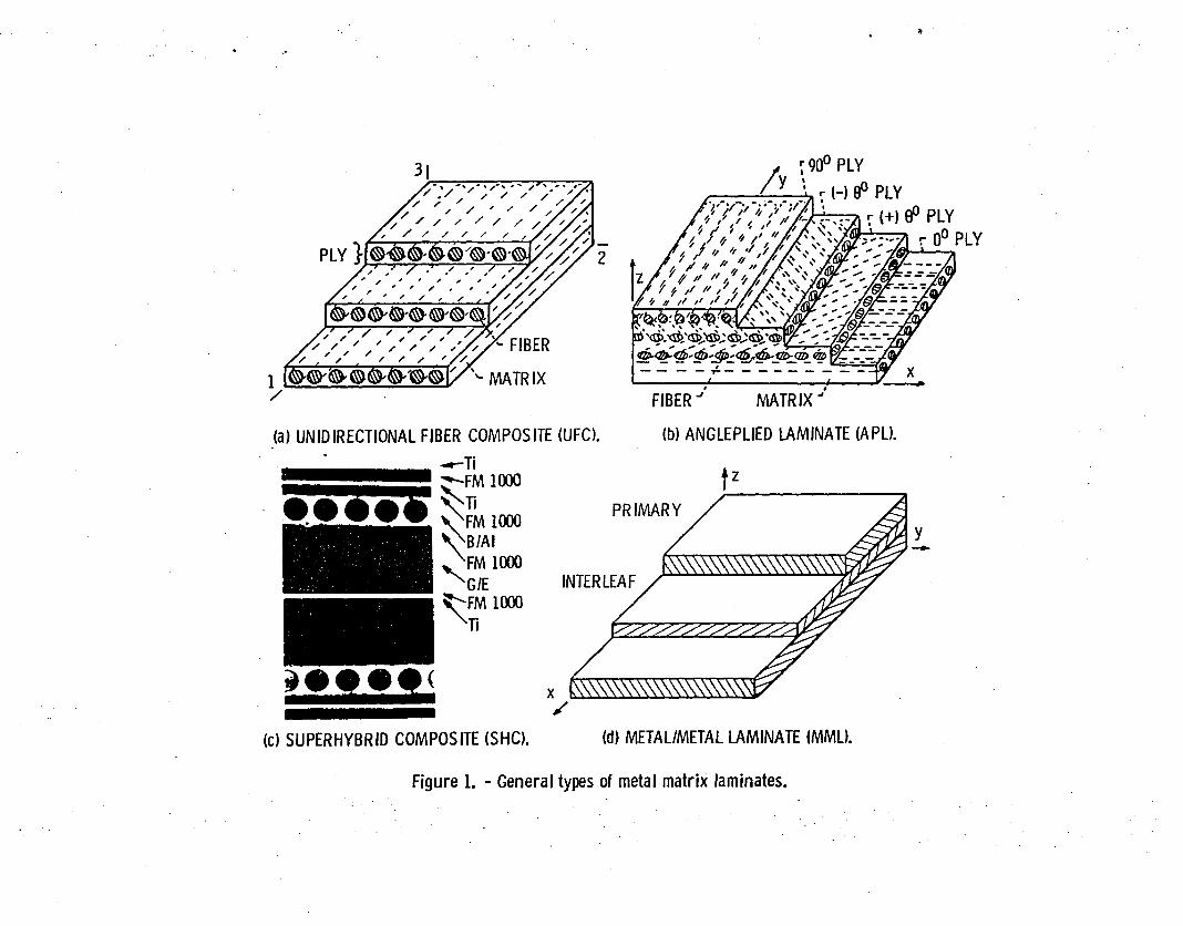
metals. Fiber-reinforced metals consist of unidirectional fiber composite
(UFC) laminates, as depicted schematically in figure l(a), and angleplied
laminates (APL), figure l(b). In both UFCand APL laminates, metallic foils
may be used between plies to enhance certain mechanical properties as will be
discussed later. Superhybrid composites (SHC) consist of outer metallic
foils, boron/aluminum plies (B/AI), graphite-fiber/resin (UFC) inner or core
plies, and adhesive film between these as shown in the photomicrograph in
figure 1(c). Metallic laminates consist usually of alternate layers from
different metals as depicted schematically in figure l(d). The various
procedures that are used to fabricate these laminates will be described
later. The combinations of materials that are used to make these laminates
are described below.
The basic unit used to study, design and fabricate UFC laminates is the
single layer (ply, monolayer, lamina) which consists of stiff, strong fibers
embedded in a metal matrix. Tile fibers and the matrix are generally called
the constituent materials, or constituents, of the laminate (composite) in the
composites community literature. Various constituents that have been used to
make UFC are summarized alphabetically under the heading fiber reinforced
4
metal laminates (first two columns in table 1). As can be seen in this table
a large number of constituent materials are used for both fibers and
matrices. The materials for fibers range from alumina to whisker. Those for
matrices range from aluminum to superalloy. The constituents used thus far
for SHChave been those summarized under superhybrids in table I. The
constituents that have been used for metallic laminates are summarized in the
last two columns of table 1. An extensive list of constituent combinations
for metallic laminates is tabulated in Kreider (ref. 4, page 40), and a list
of constituent combinations for metallic laminates made by explosive bonding
is also tabulated (ref. 4, page 49).
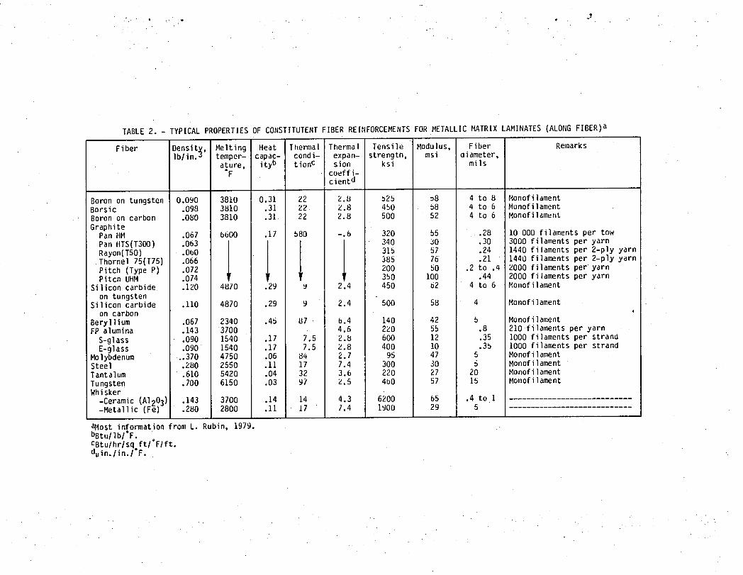
Mechanical and physical properties of constituent fiber reinforcements for
MMLs are summarizea in table 2. Part of the data in this table is from Rubin
(ref. 6). That for the whiskers is from McCreigllt, et al. (ref. 7).
Corresponding properties for metal matrices and metallic constituents for MMLs
are summarized in table 3.
FABRICATIONPROCEDURES- BRIEF DESCRIPTION
Metal matrix laminates (MMLs) are generally fabricated using diffusion
bonding, roll-bonding, coextrusion, explosive bonding and brazing.
Several other fabrication methods are also used, depending on the type of
constituent metal used in the laminate. These methoas include: vacuum
infiltration casting, high energy forming, flow molding, plasma spraying, hot
pressing, continuous infiltration, powder metallurgy methods for discontinuous
fiber composites, explosive welding and superplastic forming (Kreider (ref. 4)
and Renton (ref. 5)).
In diffusion bonding, tile filaments or tile interleaf layers (plies) are
hot pressed between layers of the matrix material. For example, for aluminum
5
matrix laminates, the pressures usuallyrange up to 20,000 psi and tile
temperature up to 2200° F. In roll-bonaing, the layers in the metal/metal
laminates are bonded by mill rolling under specified temperatures and
• pressures. In the case of fiber-reinforced metals, first, the ply (monolayer)
is formed by diffusion bonding , or one of the other methods, and seCond, the
,_ laminate of the specified number of plies is made by roll-bonding or
hot-pressing. In coextrusion, the constituents are assembled in a billet and
are extruded through a given die at specified temperatures and pressures•
depending on the constituents used. The primary bonding mechanism in the
coextrustion process is diffusion bonding. Coextrusion is particularly suited
for round and rectangular shaped bar stock. In explosive bonding, the
constituent metal plies are bonded into a laminate by the high pressure
generated through explosive means. The amount of charge used is determined by
•the metallurgical bond required between the plies. This method is especially
suitable for fabricating MMLsfrom metal plies with widely different melting
temperatures. In brazing, bonding of the constituent metal plies into a
laminate is accomplished by a third metal constituent (brazing foil) which
acts as a wetting liquid-metal phase and which has a lower melting temperature
than either•of the constituent metals. The plies to be bonded are stacked •
into a laminate with brazing foils between them. The temperature is then -.
raised to between the melting temperature of the brazing foils and the
constituent plies, and appropriate pressure is applied. Upon solidification,
the brazing foil bonds the adjacent constituent plies together into a
laminate. The temperature for fabricating boronJaluminum plies is about
1100° F while the pressure is less than 200 psi.
Superhybrids are fabricated by adhesively bonding titanium or other metal•
outer plies over composite plies such as boron/aluminum plies and
6
graphite-fiber/epoxyinner plies (core)and sometimeswith a titaniumor other
metal ply at the center (Chamis,et al. (refs.8 and 9)). The adhesivebond
betweenthe metallicplies and betweenthe metallicand compositeplies is
provided by using epoxy adhesivefilm approximately1 mil thick. The bonding
process is accomplishedunder a specifiedpressureand temperaturenormally
used for epoxy-matrixcomposites. For example,this processmight be a 3-hour.....
cure at a temperatureof 300° F under a pressureof 100 psi. The same bonding
process(fabricationprocedure)is used to fabricatethe nongraphitic
superhybrids,the Tiber hybrids(titanium/beryllium)and the adhesivelybonded
metallic-plylaminates.
TYPICALPHYSICAL,THERMALAND MECHANICALPROPERTIES
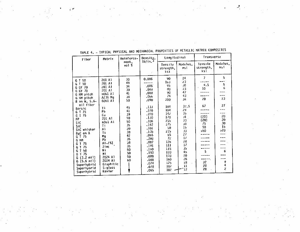
Typical physicaland mechanicalpropertiesof fibrousMMLs that have been
made are summarizedin table 4 The last three entriesin this table are
superhybridcomposites (fig. 1(c)) where the core is made from graphitefiber
(GRAPHITIC)composite,S-glassfiber (S-GLASS)composite,or Kevlar fiber
(KEVLAR)composite. It can be seen in table 4 that MMLs can be made with
densitiesrangingfrom 0.065 to 0.270 ib/in.3, longitudinalstrengths
rangingfrom 50 to 200 ksi, and longitudinalmoduli rangingfrom 11 to 45
million Ib/in.2. It can also be seen in table 4 that fibrousMMLs have
relativelylow transverse(T) strengthsrangingfrom about 5 to 75 ksi.
The transversemoduli range from 2 million Ib/in.2 for the superhybrid
• to 30 million Ib/in.2 for the SiC/Ti. The transversepropertiesfor several
fibrousMMLs listed in table 4 are not available. These propertiesas well as
•those of metallic laminates(fig. l(d)), can be predictedapproximatelyby the
methods summarizedin the sectionDESIGN/ANALYSISPROCEDURES.
7
Mechanical, thermal and physical properties are used in selecting fibrous
MMLsfor possible use in structural components during the preliminary design
phases. These properties are then verified by selective testing and are
subsequently used in the detailed analysis and the final design phases.
DESIGN/ANALYSISPROCEDURES
Designing structures with metal matrix laminates (MMLs) necessitates use
of MMLs in structures and structural parts in a cost effective way. Design
requirements for structures may be: maximumstrength witn light weight, long
life service with minimum strength degradation, notch or other defect
insensitivity with high stiffness, impact resistance with high stiffness,
damage tolerance with high stiffness, and low manufacturing and maintainance
cost.
Because building or fabricating large or complex structures frequently is
a single, nonrepetitious operation, there may be no time or money to evaluate
alternative design concepts by trial and success. Therefore, alternate design
concepts for a specific case are evaluated on paper. The fomlal way to
evaluate structural concepts with respect to given design requirements is by
the use of structural analysis. Structural analysis includes a collection of
mathematical models (equations). These equations describe the response of the
structure to the anticipated loads which the structure will have to resist
• safely during its life time.
A general structural analysis model in equation form is given by
Mu + Cu + Ku : F (1)
Equation (i) describes the structural response at any point in the structure
in terms of acceleration (u), velocity (u) and displacement (u) for a given
mechanical and/or thermal load condition (F). The structure's geometric
configuration and material are represented in equation (1) in terms of mass
(M), damping (C), and stiffness (K). Equation (1) applies to simple and/or
complex structures made from any material. In order to use equation (1) for a
structure or structural part made from a given material, tile property •values
in M, C, and K for this material must be known.
Procedures for using equation (i) for the analysis and/or design of
structures made from composite laminates are extensively aiscussed by Chamis
(refs. i0 and 11). Herein, we are concerned mainly with determining the MML
properties for M, C, and K to be used in equation (i). Weare also
concerned with strength and thermal properties wiMch are needed to evaluate
and/or select MMLsfor specified design requirements.
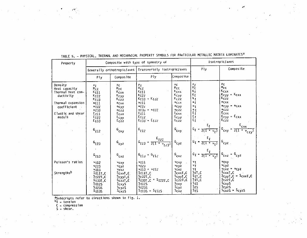
If the MMLbehaves like a general orthotropic solid (ref. 10, page 8),
then physical, thermal and mechanical properties that are needed for
structural analysis of MMLs (figs. l(b) and l(d)) include: density (p), heat
capacity (Hc) , three thermal heat conductivities (k with subscripts), three
thermal expansion coefficients (_), three normal (Young's) moduli (E), three
shear moduli (G), tnree Poisson's ratios (_) and nine strengths (S). Except
for p and Hc, the other properties are given with respect to three
mutually orthogonal directions which are taken to coincide with the planes of .
elastic symmetry of tile MML. These directions are 1, 2, and 3 in figure l(a) .....
and are referred to as the material axis of the single layer (ply). Or x, y,
and z in figures l(b) and l(d) and are referred to as structural or load
axis of the laminate (composite). It is customary to use subscripts to denote
; the directions along which the properties are given. The subscript _ in
combination with subscripts 1, 2, and 3 is usea to denote ply material axis
properties, while the subscript c in comoination with subscripts x, y, and
h!i......
z is used to denote compositestructuralaxis properties. For examples,
EllI .denotesthe modulus of elastipity (normalmodulus) in the 1-direction
and Gll2 the shear modulus in the 1-2 plane (fig. l(a)). The
• correspondingmoduli along the structuralaxis of the MML (figs.l(b) and l(d)
_ are Ecxx and Gcxy. These propertiesare summarizedin symbolicform in
table 5 for MMLs with three types of symmetry. As previouslynoted, the
material axis propertiesare for the single layer (ply) while the structural
axis propertiesare for t_lelaminate(composite).
Theories have been developed,verifiedand are availablefor predicting
material axis and/or structuralaxis propertiesbased on constituent
properties. These theoriesare includedin the generalfieid of composite
mechanics (ref. 12). Compositemechanicsis subdividedinto micromechanics,
macromechanicsand laminatetheory. Micromechanicsembodiesthe various
theorieswhich are used to predictmaterialaxis propertiesof unidirectional
fiber composites(plies)using constituentfiber and matrix properties.
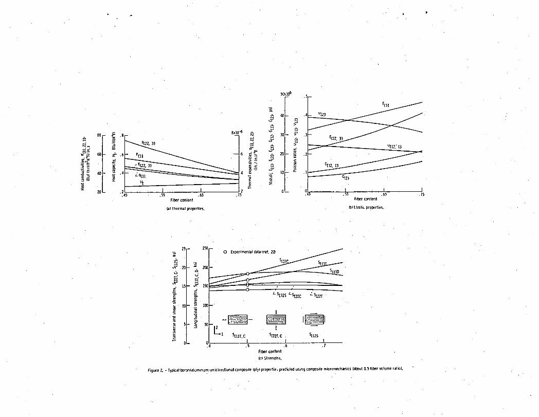
Typical resultspredictedfor boron/aluminumplies using composite
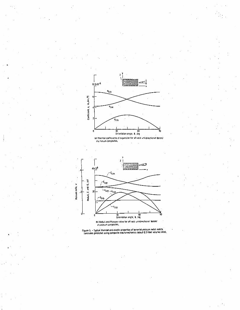
micromechanicsare shown in figure 2. Macromechanicsincludestransformation
equationswhich are used to transformmaterial axis propertiesto other axis.
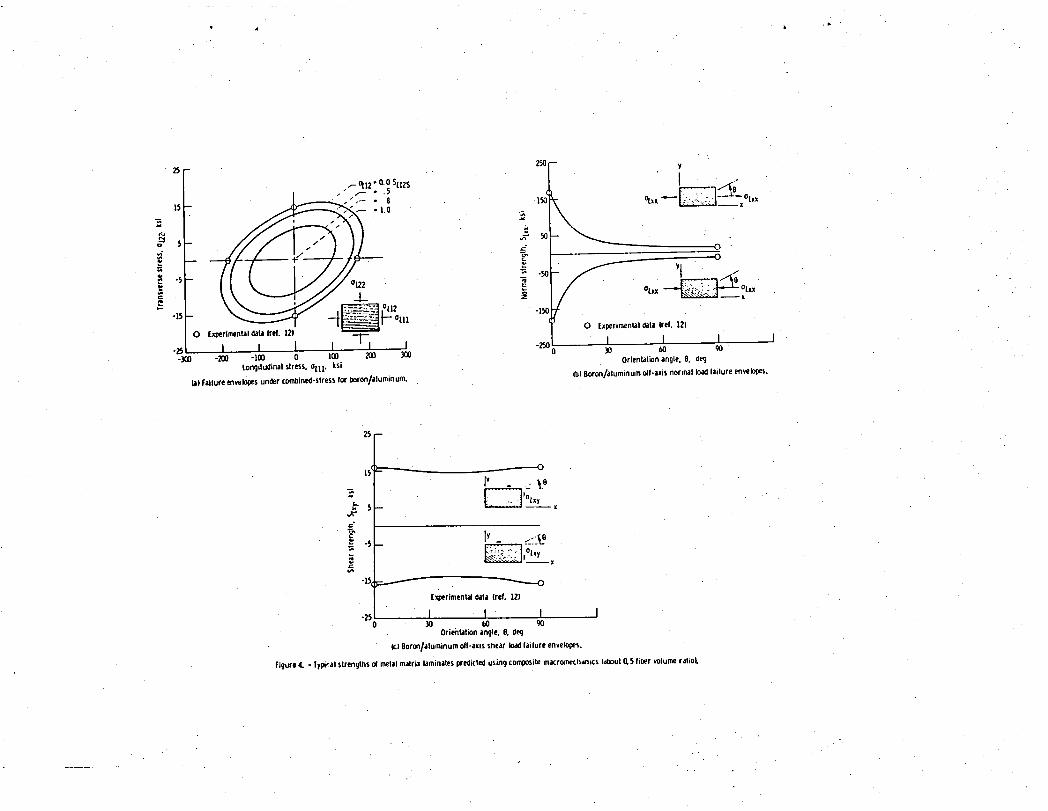
Macromechanicsalso includesfailuretheoriesand failurescriteriafor plies
subjectedto combined stresses. Typical resultspredictedfor boron/aluminum
MMLs using compositemacromechanicsare shown in figure 3 for thermaland
elastic propertiesand in figure 4 for strengths. Laminatetheory embodies
the equationsand procedureswhich are used to predictthe laminateproperties
using ply properties. Laminate theory is also used to generatethe properties
requiredto form the M, C, and K matrices (ref. 11, page 231; refs. 13 and
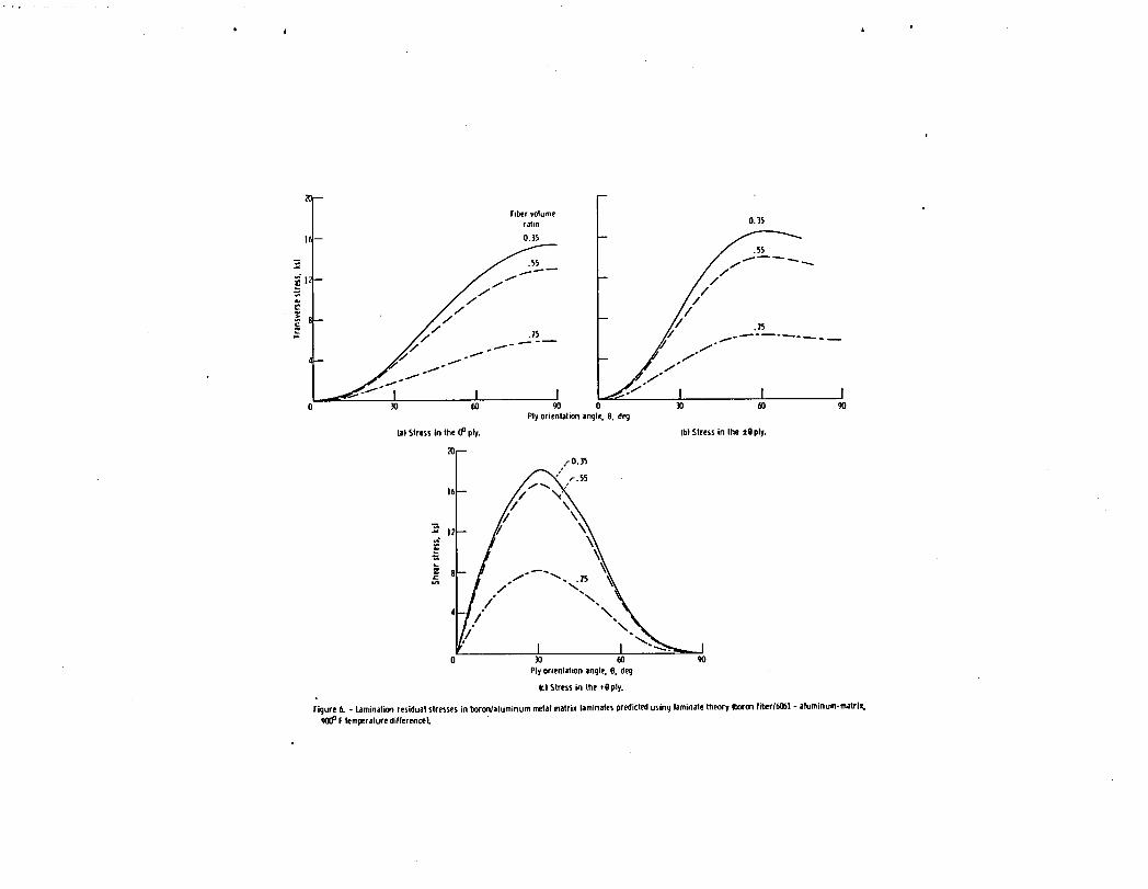
14). In addition,laminatetheory is used to predictthe laminationresidual
stressesin the plies. These residualstressesresultfrom the aifference
10
betweenthe processingand use temperaturesas well as the differencebetween
the thermalexpansioncoefficientsof the constituents(refs.15 and 16).
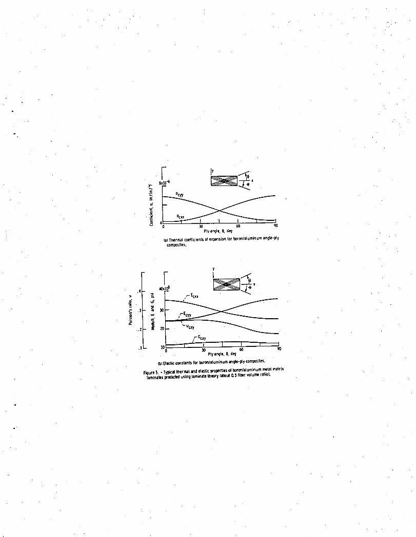
Typical resultspredictedfor boron/aluminumMMLs using laminatetheory are
shown in figure 5 for thermalexpansioncoefficientsand elasticproperties,
_. and in figure 6 for laminationresidualstresses. Laminationresidual
stresses(strains)affect significantlythe laminatemechanicalbehaviorof
boron/aluminumMMLs (ref. 16) Differenttypes of heat treatmentalso affect •_
the mechanicalbehaviorof MMLs, especiallythe transverseproperties(ref. 5,
page 72).
When MMLs are made from isotropicplies (fig. l(d)),the analysisis
considerablysimpleras comparedwith that used for fiber compositeplies.
One such an analysis is describedin detail in Chamis and Lark (ref. 17).
Typical resultsobtainedusing this analysisare summarizedin table 6 for
titanium/beryllium(Tiber)hybridMMLs.
Tilethermaland mechanicalpropertiesof MMLs as describedpreviously
constitutea minimum of the propertiesusuallyrequiredto assessthe
suitabilityof a relativelynew material at the preliminarydesign stage.
Severalother importantfactorsneed De consideredsimultaneouslywith the
thermaland mechanicalproperties. Some of these factorsare: fatigue
resistance,creep, impactresistance,erosionand corrosionresistance,
serviceenvironmenteffects,notch sensitivityand fracturetoughness,damage
toleranceand repairability,fabricationand qualitycontrol,reliabilityand
durability,inspectabilityand maintainability,design data developmentcosts
: and reproducibility,design/analysisexperienceof the staff and acceptanceof
the public agencywhich sets and administersstructuralintegritylsafety
requirements.
.
11
SPECIALTYPESOF METAL/METALLAMINATES
Special types of metal/metal MMLsthat have been investigated include
(table 1): (1) different plies of steels such as mild, high-strength and
maraging, (2) aluminum/aluminum, (3) titanium/titanium and titanium/aluminum,
(4) tungsten/superalloy and tungsten/tantalum, and (5) titanium/beryllium.
• One important reason for making and investigating these types of MMLs is their
• potential for fracture control and damage tolerance. Fracture control•
characteristics are usually assessed by using a material property called
fracture toughness. The fracture toughness of a plate-form material, with a
crack-like defect, is established by the stress that the material can resist
prior to onset of rapid crack propagation. Fracture toughness is different
for different materials. It is also different for the same generic material
but with different alloying elements, thicknesses and heat treatments. In
addition fracture toughness depends on temperature. In principle, then, by
interleaving materials with different fracture toughnesses, the fracture
toughness of MMLscan be altered and controlled within certain limits.
For analysis/design purposes, fracture toughness is used to determine the
level of stress that a structural member with a given defect or crack size can
• safely support. This level of stress is usually determined using linear
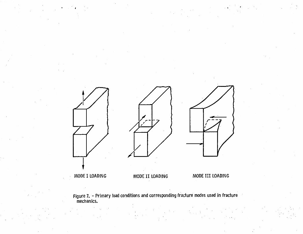
elastic fracture mechanics (LEFM). A basic equation from LEFMfor a panel
with a center-through-crack is the following
Kc• o = F (2)
where o is the averageor gross stress (stresswithoutthe crack),K isc
. the material fracturetoughnessparametercorrespondingto the primaryloading
conditionsand crack propagationdirectionsdepictedschematicallyin
figure 7, a is the crack length;and F representsthe stress state at the
12
crack tip and depends on: (1) material, (2) geometry, and (3) loading
condition. Values for K for different materials are found in reportsc
published by the Metals and Ceramics Information Center (ref. 18) as well as
in various handbooks dealing with aerospace structures and pressure vessel
" materials and design. The determination of F, on the other hand, generally
requires complicated stress analyses which frequently are performed using
finite element analysis.
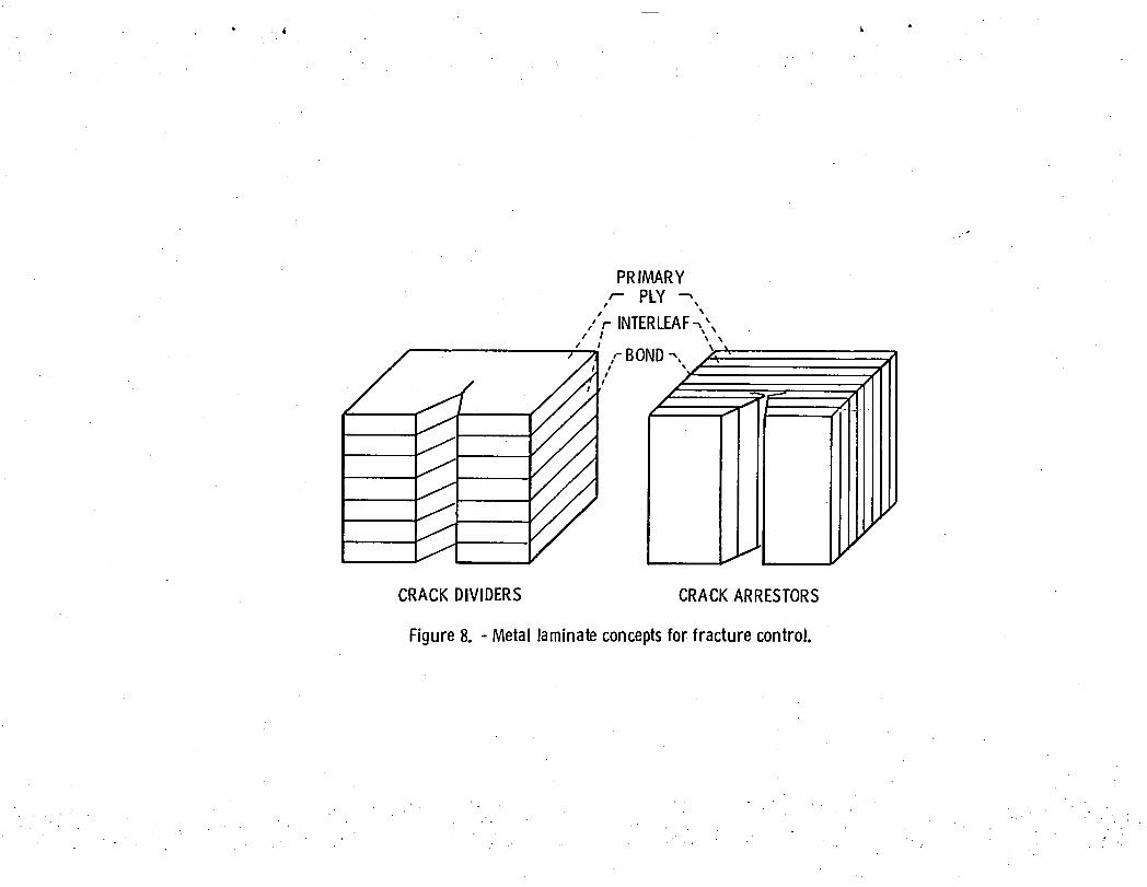
The designer can use MMLsto control (prevent or limit) fracture, and
thereby provide improved damage tolerance, in two ways: (1) using plies of
materials with different fracture toughness to divide the fracture driving
stress (crack divider), and (2) using plies with higher fracture toughness to
arrest the fracture driving stress (crack arrest). Both of these are
illustrated schematically in figure 8. In order for either concept to work,
the type of bond has to be selected to meet three general criteria: (1)
sufficiently strong to constrain the laminate to respond structurally (with
respect to displacement, buckling and frequency) like a homogenousmaterial,
(2) sufficiently flexible to permit each ply to fracture independently of its
neighbors, and (3) sufficiently brittle to fail by local delamination in the
vicinity of the advancing crack front. Goolsby (ref. 19) discusses the
fracture toughness of aluminum/aluminum MMLsfabricateo by diffusion, roll, or
explosive bonding while Koch (ref. 20) discusses those made by adhesive
bonding. Photomicrographs depicting arrested cracks in actual samples are
shown in Mileiko and AnisIlenkov (ref. 21). Oberson (ref. 22) provides a
concise treatment of fracture analysis for aerospace metals while Miska
(ref. 23) provides a comparable treatment for fatigue.
The root of a helicopter rotor blade is an example where MMLsare used for
fracture control. This part of the blade may have crack-like defects because
13
of the joint geometry and fabrication procedure as well as being subjected to
high cycle fatigue. Wings of military aircraft and helicopter booms are
potential applications for MMLs in order to provide damage tolerance for
projectile impact.
In addition to providing fracture control• or damage tolerance, MMLsare
. also used in applications where the interleaf may be the stronger, stiffer
material while the primary material provides erosion, corrosion, oxidation or
other service environmental resistance. Examples are tantalum/tungsten MMLs
which are being investigated for possible use in aircraft engine turbine
blades. Tantalum with a suitable coating is used to resist the corrosive
environment of the burning fuel while tungsten is used for strength and
stiffness in order to meet mechanical design requirements.
SPECIALTYPES OF FIBER-REINFORCEDMETALS
Boron-fiber/aluminum-matrix(B/A1)MMLs have been made and investigated
more extensivelythan those of any other fiber-reinforcedmetal. This type of
laminatecombinesseveraiof the desirablefeaturesof aluminumand, in
addition,provides about a threefoldimprovementin modulus and about a
sixfoldimprovementin strengthover that of homogeneousaluminum. One
disadvantageis tilehigh cost of the boron fiber. And the major part of this
cost is the tungsten substrate. In order to reduce the fiber cost, research
has been done and developmentis underwayto use carbon fiber for the
substrateand/or to make largerdiameterboron fibers.
Boron-fiber/aluminum-matrixMMLs have excellentfatigue,creep,corrosion
and erosion resistance. Galvanicactionmay affect (degrade)the interfacial
bond dependingon the surfacecoatingof the fiber. These MMLs have good
temperatureresistanceup to about 300° F. They may be used with a relatively
14
small property-losspenalty up to 600° F in stiffness-controlleddesignssuch
as dimensionalstability,bucklingand vibrationfrequencies. BIAI MMLs have
improvedfracturetoughnesscomparedto the aluminummatrix and are
notch-insensitive.However, dependingon the aluminumalloy and fabrication
procedure,B/AI MMLs may have about one-halfthe impactresistancecomparedto
aluminum. Christianand Adsit (ref. 5, pages 67 to 97) providean extensive
discussionon variousmechanicalpropertiesof B/AI MNLs. The elevated
temperatureeffectsare discussedby Sullivan(ref. 24). Limiteddata
available(Shrammand Kasen (ref. 25)) indicatethat cryogenictemperature
conditionshave negligibleeffect on the tensilepropertiesof B/AI MMLs.
AnglePliedB/AI MMLs (fig. I(D)) undergoinelasticdeformationsat
relativelysmall load (about 10 to 20 percentof the fracture load)
(ref. 26). In a cyclic load condition,these inelasticdeformationsmay
progressivelyimproveor degradeor have no effect on the mechanical
propertiesof the laminate(ref. 27). Conventionalmetal joiningand
repairingtechniquesare used for B/AI MMLs as well. Significantparameters
affectingjoints and joint designsare discussedby Janes (ref.28).
Boron/aluminumMMLs have been made for a varietyof structuralcomponents
such as aircraftfuselage skins and stringers,aircraftwing skins,aircraft
wing boxes, aircraftengine fan and compressorblades,propellershells,
landinggear struts,thrust supportstructuresfor the space shuttle,shafts
for torque transmission,and rocket motor cases. Photographsof some of these
structuresare shown in figures 9 to 12. Miller and Robertson(ref.5,
pages 99 to 157) providean extensivediscussionon the applicationof B/AI
MMLs for aerospacestructures. Becauseof the high cost (about$250/Ibin
1980 dollars)B/AI MMLs have not been consideredseriouslyfor use outsidethe
i
15
aerospaceindustryas yet except in limitedrecreationapplicationssuch as
tennis raquetsand bicycleframes.
Graphite-fiber/aluminum-matrix(Gr/Al)MMLs are now being investigated
. mainly for B/AI MML replacementbecauseof their low-costpotential(about5
to 10 percentof B/AI MMLs). In addition,Gr/Al MMLs have excellentthermal
dimensionalstability. They may be suitablefor use as superconductors
becauseof their excellentthermalconductivityand good mechanicalproperty
retentionat cryogenictemperatures. Gr/Al MMLs may also be suitablefor
friction-wearapplicationsbecauseof the inherentlubricatingpropertiesof
the graphitefibers. However,Gr/AI MMLs are much more susceptibleto
galvanicaction than are B/AI MMLs. Special surfacetreatmentof the fibers
is requiredto minimize this galvanicaction. Gr/Al MMLs that have been made
to date exhibit"rule-of-mixtures"propertiesalong the fiber direction
(table4). However,the transversepropertiesare relativelypoor.
Alternativessuch as heat-treatingand metal-foil interleavingare used to
improvethe transverseproperties. These alternativesare selectedwith
considerablecaution since they tend to degradethe longitudinalproperties.
Gr/Al MMLs have good fracturetoughnessand damage tolerance. They also have
excellentmechanicaland thermalfatigueresistance. Their corrosionand
erosion resistanceis comparableto that of B/AI. Pfeifer (ref. 5, pages 159
to 255) providesan extensivediscussionand a good review of several
- important apsects of Gr/Al MMLsup to 1976.
_. Borsic-fiber/titanium-matrixand Borsic-fiber/aluminum-matrixMMLs have
been investigatedprimarilyfor possibleuse in aircraftturbineengine fan
blades. Borsic/titaniumMMLs have about twice the stiffnessand about 80
percentof the density of titanium (ref.4, pages 269 to 318 and ref. 29).
The combinationof these two propertiesis generallysufficientto eliminate
16
the midspan shrouds which are presently used to meet vibration and flutter
design requirements.
Tungsten-fiber/superalloy (TF/SA) MMLshave been investigated for their
potential use in aircraft turbine blades. The excellent mechanical propertyi
q,
retention of the tungsten fibers at high temperatures (about 2000° F) is the
key feature for investigating this type of laminate. However, TF/SA have two
major disadvantages: (i) high density and (2) low cycle thermal fatigue
degradation due to thermal expansion mismatch of the constituents. T_e high
density disadvantage may be circumvented to some extent by appropriate
structural design configurations, such as nollow blades. On the other hand,
the low cycle thermal fatigue degradation can only be minimized by
metallurgical considerations. Most of the research to date for TF/SA MMLswas
conducted at laboratory level, Signorelli (ref. 30 and ref. 4, pages 229 to
267). Limited research has been initiated recently to make turbine blades
from these laminates (refs. 31 and 32).
Whisker-reinforced metals and ceramic laminates also have been
investigated for possible use in internal combustion engines and other high
temperature applications. Disadvantages for these MMLsinclude the high cost
of the whiskers and the problems associated with whisker matrix reaction which
leads to poor interfacial bonding. Additionally, whisker-reinforced ceramic
MMLshave poor fracture toughness and poor impact'resistance characteristics.
These poor characteristics may be improved by designing the laminate to
operate in preferential compression.
Someof the other fiber-reinforced MMLs listed in table 4 have been
investigated for specific applications. For example,
graphite-fiber/magnesium-matrix MMLswere investigated for space antennas
because of their desirable thermal distortion and low density properties,
17
while graphite-fiber/lead-matrix MMLswere investigated for use in batteries
where weight is an important design consideration. Someother MMLs listed in
table 4 were investigated for metallurgical considerations at tne fiberlmatrix
interface (borsic/aluminum, silicon carbide/aluminum). Still others nave been
or are being investigated at the laboratory level for scientific interest.
HYBRIDS
A general concensus definition for 'I1ybria composite' may be summarized as
f_ollows: "A hybrid composite is that composite which combines two or more
different types of fibers in the same matrix, or one fiber type in two
different matrices or combinations of these (ref. 33, pages 1337 to 1339).
Superhybrids (fig. 1(c)) are a generic class of composites which combine
appropriate properties of fiber/metal-matrix composites, fiberlresin-matrix
composites and/or metallic plies in a predetermined manner in order to meet
competing and diverse design requirements (refs. 8 and _). Tiber hybrids have
been used by the author and his collegues as an acronym for titanium/beryllium
adhesively bonded metallic laminates (ref. 17).
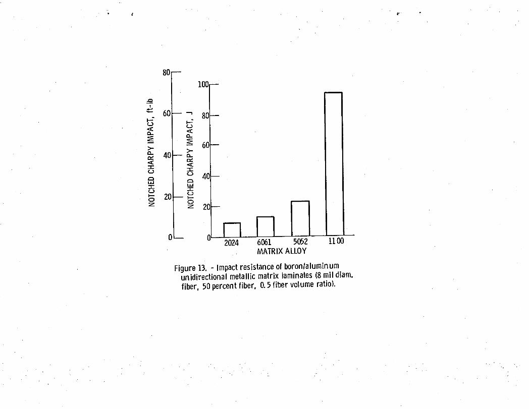
Boron-fiber-reinforced 1100, 2024, 5052, or b061 aluminum alloys nave been
investigated for use in fan blades for aircraft turbine engines. Different
diameter boron fibers (8 and 5.6 mil) may be included in the same hybrid. The
•• high impact resistance of the 8-mil-diameter boron fiber in the 1100 aluminum
alloy matrix (fig. 13) is combined with the nigh transverse tensile and shear
properties of the 8- or 5.6-mil-diameter boron fiber in either 2024, 5052, or
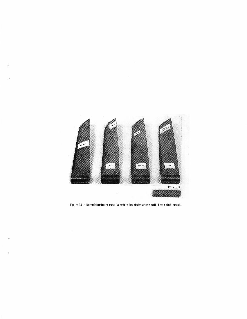
' 6061 aluminum alloy matrix. Fan blades made from some of these hybrids and
subjected to a small bird (3 oz starling) impact are shown in figure 14. The
advantages anu disadvantages of these types of hybrids are described by
18
McDanels and Signorelli(ref. 34) whi]e their use for fan blades is described
by Brantly and Stabrylla(ref. 35).
Superhybridshave been developedprimarilyfor use in fan blades for
aircraftturbineengines. This type of superhybridgenerallyhas (1)
longitudinalstrengthand stiffnesscomparableto advancedfiber composites,
(2) transverse flexural strength comparable to titanium, (3) impact resistance
comparable to aluminum, (4) transverse and shear stiffness comparable to
aluminum, and (5) density comparable to glass-fiber/resin composites
(ref. 8). In addition, superhybrids are notch-insensitive and are not
degraded by thermal fatigue (ref. 9)° Impact resistance data for
superhybrids, other fiber composites, and some metals are summarized in
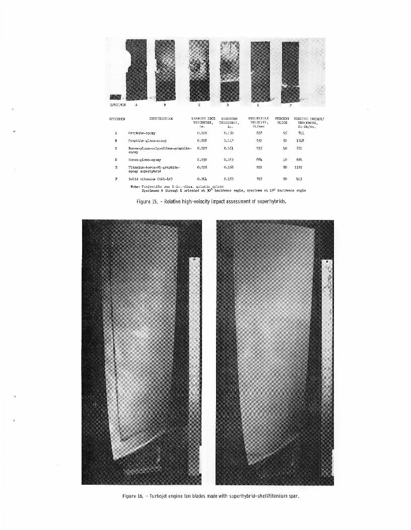
table 7. The high-velocity impact resistance of superhybrid wedge-type
cantilever specimens relative to other composites and titanium is shown in
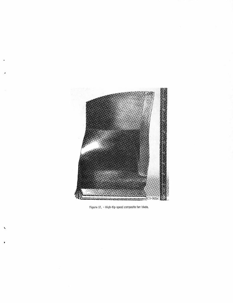
f_gure 15 (ref. 36). Large fan blades made by bonding a superhybrid shell
over a titanium spar (either leading-edge or center) are snown in figure 16
(ref. 37).
Experimental data generated at Lewis Research Center showed that Tiber
hybrids can be made which have: (i) moduli equal to that of steel, (2) tensile
fracture stresses comparable to the yield Strength of titanium, (3) flexural ....
fracture stresses comparable to the ultimate strength of titanium, and
(4) densities comparable to aluminum (ref. 17). The relatively high
stiffnesses of Tiber hybrids and their re]atively low densities compared to
conventional metals make them good candidates for compression members in
aircraft and space structures. Buckling stresses for plates and shells from
Tiber hybrids are compared with those from advanced unidirectional composites • •
and from conventional metals in table 8. As can be seen Tiber hybrids have
superior buckling resistance compared to either other advanced composites or
19
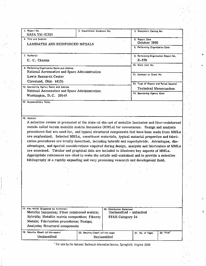
conventionalmetals. Anotherpotentialuse for Tiber hybridsis in
high-tip-speedfan blades (fig. 17) for turbojetengines. Finite element
analysisresultsshowed that Tiber hybridfan bladeswould have higher
frequenciesand lower tip distortionscomparedto those made from graphite
fiber/resincomposites(ref. 14). The comparisonsfor the first five
frequenciesfor one fan blade design are summarizedin table 9.
CONCLUSIONS
This article presents a selective review of the state-of-the-art of
metallic laminates and fiber-reinforced metals, called herein metal matrix
laminates (MMLs). Design/analysis procedures that are used for, and typical
structural components that have been made from MMLare emphasized.
Specifically, the review covers the description of selected MMLslaminates,
constituent materials and material properties, fabrication procedures,
design/analysis procedures, special metallic and fiber-reinforced MMLs,
hybrids and superhybrids, and structural components. The review shows that
(1) the methodology is available to design and analyze structural components •
from MMLs, (2) the technology is available to fabricate structural components
from these laminates and (3) a wide range of constituent metals and fibers,
and lamination concepts for MMLsare available to meet diverse and competing
design requirements. Though MMLsnave several advantages with respect to
structural design requirements, they also have different properties in
different directions and have relatively high initial (residual) stresses. •
• Both of these need special attention by the designer/analyst and the
fabricator in designing and fabricating structural parts from MMLs.
2O
REFERENCES
1. M. F. Smith, "Metal Matrix Composites," Vol. 2, NTIS/PS-7810684,
National Technical Information Service, Springfield, Va., 1978.
2. D. M. Cavagnaro, "Boron Reinforced Composites," Vol. 2, NTISIPS-7910476,
. National Technical Information Service, Springfield, Va., 1979.
3. D. M. Cavagnaro, "Boron Reinforced Composites," Vol. 2, NTISlPS-7810357,
National Technical Information Service, Springfield, Va., 1978.
4. K. G. Kreider, ed., Metallic Matrix Composites, (Composite Materials,
Vol. 4), Academic Press, New York, 1974.
5. W. J. Renton, ed,, Hybrid and Select Metal Matrix Composites: A State-
of-the-Art Review, American Institute of Aeronautics and Astronautics,
New York, 1977.
6. L. Rubin, "Applications of Metal-Matrix Composites, the Emerging
Structural Materials," in The Enigma of the Eighties: Environment,
Economics, Energy, Nat. SAMPESymp. Exilib., 24th., 1979, Book 2,
pp. 1236-1249 (Science of Advanced Materials and Process Engineering
Series, Vol. 24).
7. Lo R. McCreight, H. W. Rauch, and W. H. Sutton, Ceramic and Graphite
Fibers and Whiskers, Academic Press, New York, i965.
8. C. C. Chamis, R. F. Lark, and T. L. Sullivan, "Boron/Aluminum-Graphite/
• Resin Advanced Composite Hyorids," NASATN D-7879, 1975.
9. C. C° Chamis, R. F. Lark, and T. L. Sullivan, "Super-Hybrid Composites-
• an Emerging Structural Material," NASATMX-71836, 1975.
10. C. C' Chamis, ed., Structural Design ana Analysis, Part I (Composite
Materials Series, Vol. 7), Academic Press, New York, 1974.
11. C. C. Chamis, ed., Structural Design and Analysis, Part II (Composite
Materials Series, Vol. 8), Academic Press, NewYork, 1975.
21
12. C. C. Chamis, "Characterization and Design Mechanics for Fiber-Reinforced
Metals," NASATN D-5784, 1970.
13. C. C. Chamis, Comput. Struct., 3 (3), 467 (1973).
14. C. C. Chamis, J. Aircraft, 14 (7), 644 (i977).
" 15. C. C. Chamis, "Lamination Residual Stresses in Multilayered Fiber
Composites," NASATN D-6146, 1971.
16. C. C. Chamis, "Residual Stresses in Angleplied Laminates and Their
Effects on Laminate Behavior," NASATM-78835, 1978.
17. C. C. Chamis and R. F. Lark, "Titanium/Beryllirim Laminates: Fabrication
Mechanical Properties, and Potential Aerospace Applications," NASA
TM-73891, 1978.
18. Metals and Ceramics Information Center, 505 King Ave., Columbus, OH,
43201.
19. R. D. Goolsby, "Fracture of Crack Divider AI/AI Laminates," in ICCM2,
Proceedings of the i978 International Conference on Composite
Materials, AIME, Warrendale, Pennsylvania, 1978, pp. 941-960.
20. G. H. Koch, "The Fracture Behavior of Multiply Layer Adhesive Bonded
Aluminum Structures," in The Enigma of the Eighties: Environment,
Economics, Energy, Nat. SAMPESyrup. Exhib., 24th., 1979, Book 1,
• pp. 649-658 (Science of Advanced Materia|s and Process Engineering
Series, Vol. 24).
• 21. S. T. Mileiko and V. M. Anishenkov, "On Fatigue of Metal Matrix
Composites," in The Enigma of the Eighties: Environment, Economics,
Enerqy, Nat. SAMPESymp. Exilib., 24th., Book I, 1979, pp. 799-811
(Science of Advanced Materials and Process Engineering Series,
Vol. 24).
22. H. J. Oberson, Jr., SAMPEJ., 13, 4-11, November/December (1977).
22
23. K. H. Miska, Mater. Eng., 87 (6), 3i-33 (1978).
24. P. G. Sullivan, "Elevated Temperature Properties of Boron/Aluminum
Composites," NASACR-159445, 1978.
25. R. E. Schrammand M. B. Kasen, "Static Tensile Properties of Boron-
•Aluminum and Boron-Epoxy Composites at Cryogenic Temperatures," in
K. D. Timmerhaus, R. P. Reed, and A. F. Clark, eds., Advances in
Cryogenic Engineering, Vol. 22, Plenum Press, New York, 1977,
pp. 205-213.
26. C. C. Chamis and T. L. Sullivan,"A ComputationalProcedureto Analyze
Metal Matrix Laminateswith NonlinearLaminationResidualStrains,"
NASA TM X-71543, 1974.
27. C. C. Chamis and T. L. Sullivan,"NonlinearResponseof Boron/Aluminum
AnglepliedLaminatesUnder CyclicTensileLoading: Contributing
Mechanismsand Their Effects,"NASA TM X-7i490, 1973.
28. S. Janes, "Applicationof ConventionalJoiningTechniquesto Boron Fiber
and Carbon Fiber ReinforcedAluminum,"BattelleInstitute,Frankfurt,
West Germany,Report D2532 HI, 1976.
29. B. R. Collins, W. D. Brentnall, I. J. Totn, "Properties and Fracture
Modes of Borsic Titanium," AFML-TR-73-43, 1972.
30. R. A. Signorelli, "Review of Status and Potential of Tungsten-Wire-
Superalloy Composites for Advanced Gas Turbine Engine Blades," NASATM
• X-2599, 1972.
31. W. D. Brentnall, "FRS Composites for Advanced Gas Turbine Engine
Components," TRW, Inc., Cleveland, Ohio, Report TRW-ER-7887-F,
AD-A050 595, 1977.
23
32. D. W. Petrasek, E. A. Winsa, L. J. Westfall, and R. A. Signorelli,
"Tungsten Fiber Reinforced FeCrAIY - A First Generation Composite
Turbine Blade Material," NASATM-79094, 1979.
33. B. R. Noton, et al., eds., ICCM2, Proceedings of the 1978 International
Conference on Composite Materials, AIME, Warrendale, Pennsylvania,
1978.
34. L. McDanels and R. A. Signorelli, "Effect of Fiber Diameter and Matrix
Alloys on Impact Resistant Boron/Aluminum Composites," NASATN D-8204,
1976.
35. J. W. Brantly and R. G. Stabrylla, "Fabrication of J79 Boron/Aluminum,
Blades," General Electric Co., Cincinnati, Onio, Report R79AEG388,o
1979. (NASACR-159566.)
36. R. C. Novak, "Multi-Fiber Composites," United Tecnnologies Research
Center, Hartford, Connecticut, Report R76-912098-11, 1976. (NASA
CR-135062. )
37. C. T. Salemme and G. C. Murphy, "Metal Spar/Supernybrid Shell Composite
Fan Blades," NASACR-159594, 1979.
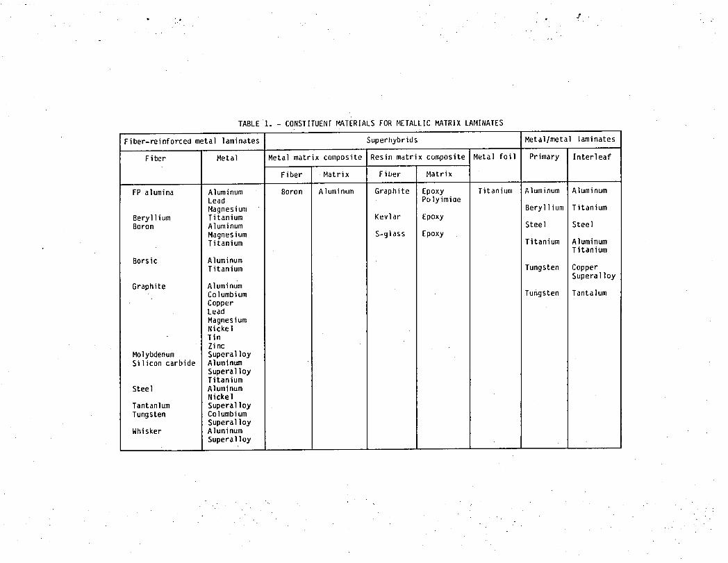
TABLE1. - CONSTITUENT MATERIALS FOR METALLIC MATRIX LAMINATES
Fiber-reinforcedmetal laminates Superhybrids Metal/metal laminates
Fiber Metal Metal matrix composite Resin mdtrix cumposite Metal foil Primary Interleaf
Fiber .Matrix Fiber Matrix
FP alumina Aluminum Boron Aluminum Graphite Epoxy Titanium Aluminum AluminumLead PulyimiaeMagnesium Beryllium Titanium
Beryllium Titanium Kevlar EpoxyBoron Aluminum Steel Steel
Magnesium S-glass EpoxyTitanium Titanium Aluminum
Titanium
Borsic AluminumTitanium Tungsten Copper
Superalloy
Graphite AluminumColumbium Tungsten Tantalum
CopperLead
MagnesiumNicke!TinZinc
Molybdenum SuperalloySilicon carbide Aluminum
SuperalloyTitanium
Steel AluminumNickel
Tantanlum SuperalloyTungsten Columbium
SuperalloyWhisker Aluminum
Superalloy
• • m • T
TABLE 2. - YPICAL PROPERTIES OF CONSTITUTENT FIBER REINFORCEMENTS FOR METALLIC MATRIX LAMINATES (ALONG FIBER)a
Fiber Densitx, Melting Heat Thermal Thermal Tensile Modulus, Fiber Remarkslblin._ temper- capac- condi- expan- strength, msi aiameter,
ature, ityb tionc sion ksi mils°F coeffi-
cientd
Boron on tungsten 0.090 3810 0.31 22 2._ 625 68 4 to 8 MonofilamentBorsic .098 3810 .31 22 Z.8 450 58 4 to 6 MonofilamentBoron on carbon .OBO 3810 .31 22 2.8 500 52 4 to 6 Monofilamer_tGraphitePan HM .067 bbO0 .17 b80 -.6 320 55 .28 10 000 filaments per towPan HTS(T300) .063 340 30 .30 3000 filaments per yarnRayon(T50) .ObO 315 57 .24 1440 filaments per 2-ply yarnThornel 75(T75) .066 385 76 .21 1440 filaments per 2-ply yarnPitch (Type P) .072 200 50 .2 to .4 2000 filaments per yarnPitcn UHM .014 Ir ' I' 350 100 .44 2000 filaments per yarn
Silicon carbide, .120 4_70 .29 _ 2.4 450 62 4 to 6 Monofilamenton tungsten
Silicon carbide .110 4870 .29 9 2.4 500 58 4 Monofilamenton carbon
Beryllium .067 2340 .45 87 6.4 140 42 5 MonofilamentFP alumina .143 3700 4.6 2ZO 55 .8 210 filaments per yarn
S-glass .090 1540 .17 7.5 2.8 600 12 .35 1000 filaments per strandE-glass .090 1540 .17 7.5 2.8 400 10 .35 1000 filaments per strand
Molybdenum ..370 4750 .06 8_ 2.7 95 47 5 MonofilamentSteel .280 2550 .11 17 7.4 300 30 5 MonofilamentTantalum .610 5420 .04 32 3.6 220 27 20 Monofilament
Tungsten .700 6150 .03 97 _.5 460 57 15 MonofilamentWhisker
-Ceramic (Al203) .143 3700 .14 14 4.3 6200 b5 .4 to I-Metallic (Fe)- .280 2800 .11 17 1.4 1900 29 5
aMost informationfrom L. Rubin, 1979.bBtullbl'F.
CBtulhrlsq ftl°Flft.d_in.lin.l F.
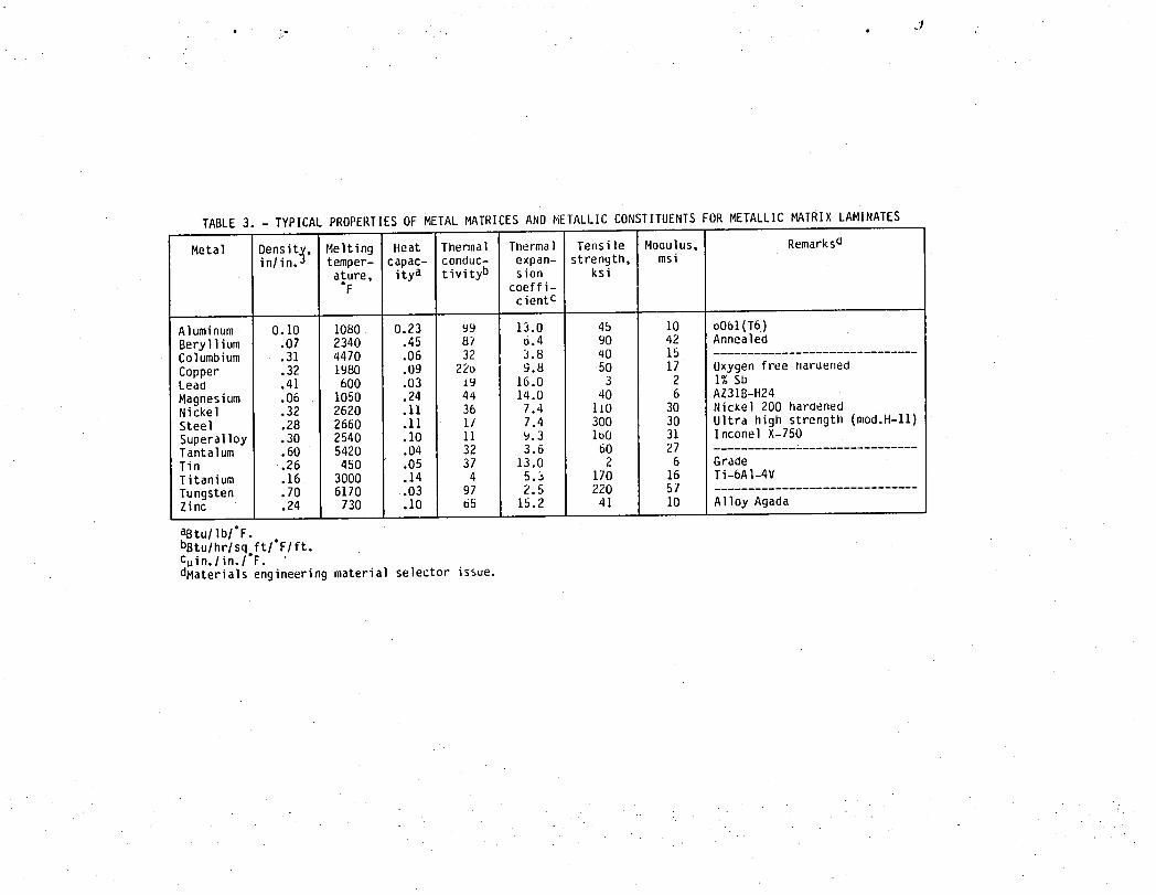
TABLE 3. - TYPICAL PROPERTIES OF MEIAL MATRICES AND METALLIC CONSTITUENTS FOR METALLIC MATRIX LAMINATES
Melting Heat Thermal Thermal Tensile Moaulus, RemarksaMetal Oensitx,inlin,j temper- capac- conduc- expan- strength, msi
ature, itya tivityb sion ksi"F coeffi-
cientc
Aluminum 0.10 1080 0.23 99 13.0 45 10 oOb1(T6)Beryllium .07 2340 .45 87 6.4 90 42 AnnealedColumbium .31 4470 .06 32 3.8 nO 15
Copper .32 1980 .09 22D 9.8 50 17 Oxygen free hardenedLeaa .41 600 .03 19 16.0 3 2 I% Sb
Magnesium .06 1050 .24 44 14.0 40 6 AZ31B-H24Nickel .32 2620 .11 36 7.4 1i0 30 NicKel 200 hardenedSteel .28 2660 .11 I_ 7.4 300 30 Ultra high strength (mod.H-11)Superalloy .30 2540 .10 11 9.3 lbO 31 Inconel X-750Tantalum .60 5420 .04 32 3.6 60 27Tin .26 450 .05 37 13.0 2 6 GradeTitanium .16 3000 .14 4 5.3 170 16 Ti-6AI-4V
Tungsten .70 6170 .03 97 2.5 220 57Zinc .24 Z30 .10 b5 15.2 41 10 Alloy Agada
aBtu/lb/°F.bBtu/hr/sq ft/°F/ft,C_in./in, l°F. •dMaterials engineering material selector issue.
TARLE 4. - TYPICAL PHYSICAL AND MECHANICAL PROPERTIES OF METALLIC MATRIX COMPOSITES
Fiber Matrix Reinforce- Density, Longitudinal Transversement, lb/in.Jvol % Tensile Modulus, Tensile Modulus,
strength, msi strength, nlsiksi ksi
G T 50 201 A1 30 0.086 90 24 7 5G T 50 201AI 49 I53 Z3 ---G GY 70 ZOl AI 34 .086 95 aO 4.5 5G GY 70 201AI 30 .088 UO Z3 10 6
G HM pitch b061AI 41 .088 90 47 ---G HM pitch AZ31Mg 3U .Obb 14 43 ---B on W, 5.6- 6061AI 50 .090 ZOO J4 ZO 23mil fiber
Borsic Ti 45 .133 184 3_.5 67 27G T 15 Pb 41 .210 104 Z9 ---G T 75 Cu 39 .220 ]42 35 ---FP 201 A1 50 .130 110 J! (20) 20SiC bObl AI 50 .106 215 33 (20) 20SiC Ti 35 .142 175 J_ /5 30SiC whisker A1 ZO .101 50 Ib 50 15B4C on B Ti 38 .135 2Ib 33 >50 >20G T 15 Mg 42 .065 65 21 ---G HM Pb 35 .280 72 II ---G T 75 AI-/%Z 38 .087 12b ZU ---G T 75 Zinc 35 .Igl Ill II ---G T bO Ni 50 .190 ll5 35 ---G T 75 Ni 50 .Ig3 120 45 5 6G (3.2 mil) 2024 A1 50 .088 110 20 ---G (5.6 mil) 2024 AI bO .08B Ib0 Z6 ---Superhybrid Graphitic .014 125 i8 32 9Superhybrid S-glass .018 101 II 28 4Superhybrid Kevlar _r .065 I02 ---_-12 28 Z
,. . • .
• i'r "
TABLE 5. - PHYSICAL, THERMAL AND MECHANICAL PROPERTY SYMBOLS FOR PAHTICULAR METALLIC MATRIX LAMINATESa
Property Composite with type of sy_t_etryof Isotropic/axes
Ger,eraIlyorthotropiclaxes Transversely isotr()piclaxes Ply Composite
Ply Composite Ply Composite
Density PI Pc P! Pc Pl PcHeat capacity Hci Hcc llc! Hcc Hc HccThermal heat con- KITI Kcxx Kill Kcxx Kl Kcxx
ductivity KI22 Kcyy K(22 Kcyy Kl Kcyy = KcxxK(33 Kczz K133 = KIZ2 Kczz kI Kczz
Thermal expansion _11 Qcxx _111 ocxx ol ocxxcoefficient _122 Qcyy ol2L Qcyy Q{ Qcyy = Qcxx
_133 aczz _I3J = _122 _czz at _czzElastic and shear EliI Ecxx EliI Ecxx El Ecxxmoduli E122 Ecyy E122 Ecyy El Ecyy = Ecxx
E133 Lczz E133 = E122 Eczz El Eczz
El Ecxx
GI12 Gcxy GII2 Gcxy GI = 2(I * _l) Gcxy = 2(I + Vczy)
El22 El
G123 Gcyz G123 = 2(I + _123) Gcyz Gl = 2(I + v[) Gcyz
El
GII3 Gcxz GllJ = GIIZ Gcxz Gl = 2(I + Vl) Gcxz = Gcyz
Poisson's ratios v{l2 vcxy v111 vcxy vl vcxyv123 vcyz v123 Vcyz vl vcyzvii3 vcxz v113 = vii2 vcxz Vl vcxz = vcyz
Strengthsb SIIIT,C ScxxT,C SIIIT,C ScxxT,C SIT,C ScxxT,C
S122T,C ScyyT,C S122T,C ScyyT,C SIT,C ScyyT,C = ScxxT,CS133T,C SczzT,_ S133T,C = S122T,C SczzT,C SIT,C SczzT,CS112S ScxyS SII2S Scxy SIS ScxySS123S ScyzS S123S Scyz SIS ScyzSS113S ScxzS S113S = S112S Scxz SIS ScxzS = ScyzS
asubscriptsrefer to directions hown in fig. I.bT = tensionC = compressionS = shear.
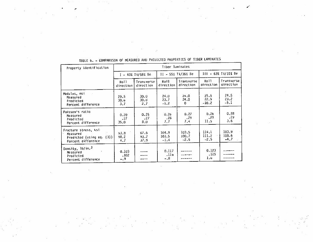
TABLE 6. - COMPARI ON OF MEASURED AND PREDICTED PROPERTIES OF TIBER LAMINATES
Property identification Tiber laminates
I - 40% Ti/58% Be II - 55% Ti/36_ Be ZIl - 63% Ti/31% Be
Roll Transverse Roll Transverse Roll Transversedirection direction direction direction direction direction
Modulus, msiMeasured 29.5 30.0 24.0 Z4.0 25.5 24.5Predicted 30.D 30.8 23.7 24.0 22.9 23.2Percent difference 3.7 2.1 -1.2 0 -10.2 -5.1
Poisson's ratioMeasured 0.20 0.25 O.2b 0.21 0.26 0.28Predicted .27 .21 .28 .29 .29 .29Percent differetlce 35.0 8.0 7.7 1.4 11.5 3.6
Fracture stress, ksii Measured 93._ 67.6 104.9 103.5 114.1 103.9
Predicted (using eq. (3)) 98.2 93.2 103.5 100.7 111.2 108.6Percent difference 4.7 37.9 -I.4 -2.5 -2.5 -4.7
Density, Iblin.3Measured 0.103 0.117 0.123Predicted .102 .11b .125Percent difference -.9 -.8 1.4
-.1 ,"
. ..
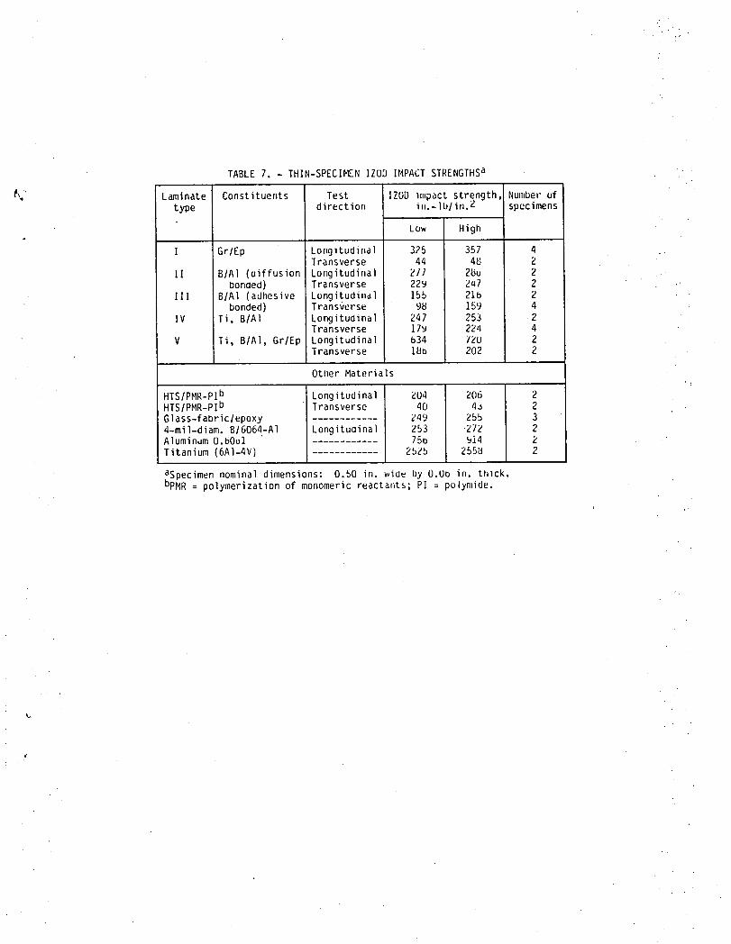
TABLE 7. - THIN-SPECIMEN IZUD IMPACTSTRENGTHSa •
_,," Laminate Constituents Test IZOD Impact strength Number uf
type direction in.-lblin.2 specimens
Low High
I GrlEp Longitudina] 325 357 4Transverse 44 4_ 2
II BIAI (oiffusion Longitudinal 211 2_o 2bonded) Transverse 229 547 2
Ill BIAI (adhesive Lungitudinal 155 216 2 .:-bonded) Transverse 9_ 159 4
IV Ti, BIA] Longitudinal 247 253 2Transverse 17_ 224 4
V Ti, B/A], Gr/Ep Longitudina| b34 72U 2Transverse 1_b 202 2
Otl_erMaterials
HTSIPMR-PIb Longitudina| 204 206 2HTSIPMR-PIb Transverse 40 4J 2Glass-fabriclepoxy Z49 255 34-mil-diam. BI6064-AI Longituaina] 253 272 2Aluminum O.b061 75b _14 2Titanium (6AI-4V) 252b Z55_ 2
aSpecimen nominal dimensions: 0.50 in. wide by O.Oo in. thlck.bpMR = polymerization of monomeric reactar,ts;P] = polymide.
i
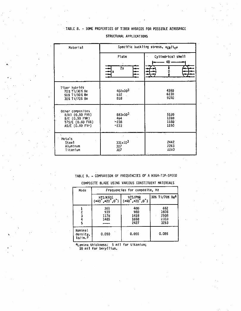
TABLE8. - SOMEPROPERTIESOF TIBERHYBRIDSFOR POSSIBLEAEROSPACE
STRUCTURALAPPLICATIONS
Material Specificbucklingstress,ocRltcp
Plate Cylindricalshell
4D .--"," 2a _ €--"" a _ D.-,,.. 4-..
Tiberhybrids70% Ti/30%Be 402x103 416050% Ti/50%Be 532 6230
30% Ti/70%Be 818 9150
OthercompositesB/A1 (0.50FVR) 883xi03 5120B/E (0.50FVR) 464 1310T75/E(0.60FVR) -238 1180AS/E (0.60FVr) -233 1150
MetalsSteel 331x103 2442Aluminum 307 2263Titanium 307 Z263
TABLE9. - COMPARISONOF FREQUENCIESOF A HIGH-TIP-SPEED
COMPOSITEBLADEUSINGVARIOUSCONSTITUENTMATERIALS
Mode Frequenciesfor composite,Hz
HTSIK601 HTSIPMR 30% Ti/70%Bea(.40, 20 ,0 ) (±40•,.20",0°)
I 361 400 6622 939 960 16083 1178 1418 21084 1485 1658 23335 ---- 2427 3253
Nominal
density, 0.050 0.055 0.085Iblin._
aLaminathickness: 5 mi for titanium;10 mil for beryllium.
~"-I Y
FIBER./ MATRIX'/
(b) ANGLEPLIED LAMINATE (APU.
PRIMARY
x/
(a) UNIDIRECTIONAL FIBER COMPOSITE lUFC).
--Ti==== ~FM 1000••; •• ~r~ llXXl'\B/AI,FM 1000
GtE'::FM 1000
Ti
(c) SUPERHYBRID COMPOSITE (SHC). (d) METAL/METAL LAMINATE (MMU.
Figure 1. - General types of metal matrix laminates.
50x106- .5_
80 _ .8 8xlO"6 _,
l I _ _ o l I I20 - "!45 55 .65 .15 . .55 .65 .15
Fibercontent Fibercontent
tatThermalproperties. (btLlashcproperties.
2_ 250,-
0 Experimentaldatatret. 221
$ ot L SLlZS LS{22C _ 5{2_.
[00--= I
5o
I S[IlT, C SI22T.C S112S- I t I
.4 .5 .6 .lFibercontent
(el Strenqths.
Figure2. - Typicalboronlalurnnum unidirectionalcomposite(ply|propertie,predictedusingcornpestternicrornechanics[aboutO.5fibervolumeratiol.
1- 2y
6 °c_ x
_ 2
60 gOOr!entationangte.0.oeg
(a)Thermalcoefficientsofexpansionforoff-axisumdirectionalboron/aluminumcomposites.
Y
I- F 2O6
m
• 4! - 40xl
I _ ECxx
I
"_ _ [ "Ecyy2-
= .2- ,..= 2(;
g.
'-rosy
T ! tI- 0 30 60 vd
Orientationangle.8. tie!
(hiM_uli andPoissonratiosforoff-axisunidirectional_ronlaluminumcomposites.
Figure3, - Typicalthermalandelasticpropertieso!boronlaluminummetalmatrix_, laminatespredictedusingcompositemacromechanicslabeutO.5fiber volumeratio).
• • b
2'_ y25
_ 511
N' 0u
" " olZ2 _E
_. [x.x txx,5 -tSO
-15_- Z°[II 0 Experimentaldata(ref. 1210 Experimentaldata(ref. 121 --1"- I I I J
-z_ I I I I --I / -z_ 3o 6o 9o-300 -200 -100 0 100 200 Orientationangle. 6 oeg
Longitudinalstress.Otl1. ksi (t))Boron/alum,numoil-axisnormalloadfailureenvelopes.5_1Failureenvelopesundercombined-stressfor boron/aluminum.
Z.5--
1.5__
-=, [v . _-_e.5 -- ['_ Iotxy - x
_-5 E__ ;_::V
ExperimentalOata(ref. IZ)
-z: I I I I3O 5O 9O
Orientationangle.6. deg
Ir.I Ooronlaluminumo/f-axisshear loadladure envelopes.
Figure4. - lypi_:alstrengthsd metalmatrixlaminatespredictedusingcompositemacromechdn=¢s(=bout0. 5hbervolumeratioL
F_. 8xlO"6
€ .
,S 40 30 60 _0Plyangle,e, de9
(a)Thermalcoefficientsof expansionfor boronteluminumingle-plycomposites.
Y
_lo6 __ ':_ /- ECxx
._.3 30
.__,o ,
• 2 20 -- VCxy
F Gcx7
I I i J.1 I0 30 60 _)
Plyangle,8, de<]
tb)Elasticconstantsfor boronlaluminumingle-plycomposites.
Figure.5.- Typicalthermalandelasticpropertiesofboron/aluminummetalmatrixlaminatespredictedusin9laminm theory(about0..5fiber volumeratio).
Fib!?r volumeraho 0.35
-- O.35 -- _._.__
_'_- _ -
.1_ - /I 7s
, ,Plyorientationangle.8. de9
tal Stressin the0° ply. (btStressin the i8 ply.
,.-0.35
g
/ I "" Itll 6O _
Plyonentatmnangle.8. €e9
V..)Stressin the +gply.
Figure6. - Laminalionresidualstressesin boronlatuminummetalmatrixlaminalespredictedusinglaminatetheoryIboronfiberlbOb!- aluminum-matrix,F temperaturedilferenceL
MODEI LOADING MODEII LOADING MODEIII LOADING
. Figure7. - Primaryloadconditionsandcorrespondingfracturemodesusedin fracturemechanics.
: . . . ...
- . " ., • .. Z
PRIMARY,- PLY -"
I
r INTERLEAF-,'i I \ \
,'" ,"'" BON__ "
CRACKDIVIDERS CRACKARRESTORS
Figure8. - Metallaminateconceptsforfracturecontrol•
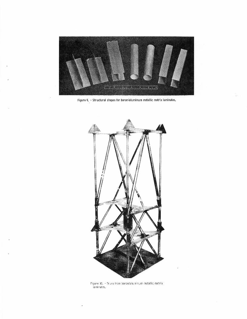
Figure9. - Structural shapesfor boron/aluminummetallicmatrixlaminates.
Figure].0. - Trussfromboron/aluminummetallicmatrixlaminates,
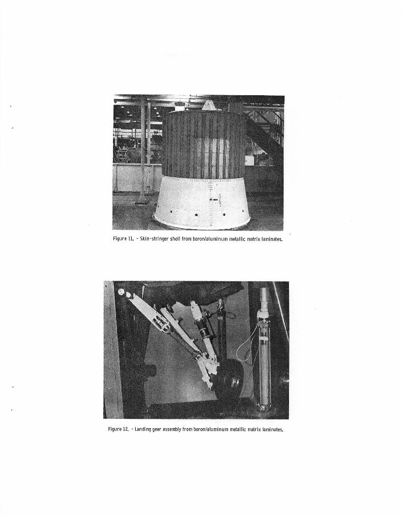
Figure11. - Skin-stringershell fromboron/aluminummetallicmatrix laminates.
Figure12. - Landinggearassemblyfromboron/aluminummetallicmatrixlaminates.
80_
I00
" 60-- 8o-
40
--I-
_- 20 _--o o
7 20
02024 6061 5052 1100
MATRIXALLOY
Figure13. - Impactresistanceof boronlaluminumunidirectionalmetallicmatrix laminates(8mil diam.fiber, 50percentfiber, 0.5fiber volumeratio).
i
os-71839
Figure14. - Boronlaluminummetallicmatrixfan bladesaftersmall(3oz.) birdimpact.
!ii!ii!¸¸ii
!!ii!fill_!!I,_
S_CIM_ A B C D E F
SPECI_N CONSTRUCTION LEADING EDGE MIDCHORD PROJECTILE PERCENT KINETIC ENERGY/THICKNESS, THICKNESS, VELOCITY, SLICE THICKNESS,
in. in. ft/see ft-lb/in.
A Oraphite-epoxy 0.029 0.150 828 55 814
D Graphite-glass-epoxy 0.028 O.147 932 50 1048
O Boron-glass-polysulfone-graphite- 0.029 O.161 935 40 801epo_
D Boron-glass-epoxy 0.030 O.163 884 40 694
E Titanium-boron-Al-graphite- 0.025 O.156 922 50 1192epoxy superhybrid
F Solid titanium (6AI-hV) 0.014 0.153 727 50 _3
Note: Projectile was 1-in.-diam. gelatin sphereSpecimens A through E oriented at 30b incidence angle, specimen at 19° incidence angle
Figure15. - Relativehigh-velocityimpactassessmentof superhybrids.
Figure18. - Turbojetenginefanbladesmadewith superhybrid-shell/titaniumspar.
Figure!7. - High-tip-speedcompositefanblade.
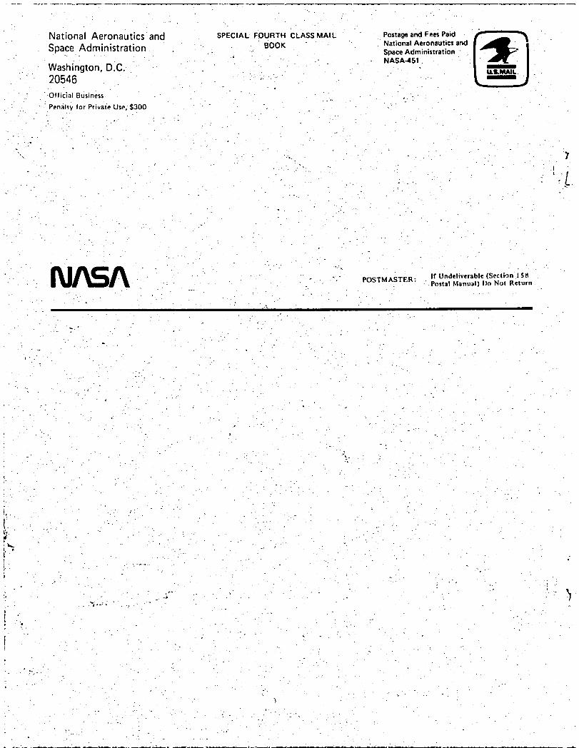
1. Report No. 2. Government AccessionNo. 3. Recipient'sCatalog No.NASA TM-81591
4. Title and Subtitle 5. Report Date
LAMINATES AND REINFORCED METALS October 19806. PerformingOrganizationCode
7. Author(s) _, 8. Performing Organization Report No.
C. C. Chamis E-570
I0. Work Unit No.9. PerformingOrganizationNameand Address
NationalAeronauticsand Space Administration
Lewis Research Center 11. Contract or Grant No.
Cleveland, Ohio 4413513. Type of Report and Period Covered
12. SponsoringAgency Name and Address Technical MemorandumNationalAeronauticsand Space Administration
14. SponsoringAgency CodeWashington, D.C. 20546
15. SupplementaryNotes
16. Abstract
A selective review is presented of the state-of-the-art of metallic laminates and fiber-reinforced
metals calledhereinmetallicmatrixlaminates(MMLs) for convenience. Design and analysis
proceduresthatare used for,and typicalstructuralcomponents thathave been made from MMLs
are emphasized. SelectedMMLs, constituentmaterials,typicalmaterialpropertiesand fabri-
cationprocedures are brieflydescribed,includinghybridsand superhybrids. Advantages,dis-
advantages,and specialconsiderationsrequiredduringdesign,analysisand fabricationof MMLs
are examined. Tabular and graphicaldataare includedtoillustratekey aspectsofMMLs.
Appropriatereferencesare citedtomake thearticleself-containedand to providea selective
bibliographyofa rapidly•expandingand very promising research and developm_entfield.
17. Key Words (Suggested by Author(s)) 18. Distribution Statement
Metalliclaminates;Fiber reinforcedmetals; Unclassified- unlimited
Hybrids; Metallicmatrix composites;Fibers; STAR Category 24
Metals; Fabricationprocedures;Design;
Analysis;Structuralcomponents
19. Security Classif.(of thisreport) 20. SecurityClassif.(of this page) 21. No. of Pages 22. Price"
Unclassified Unclassified
" Forsalebythe NationalTechnicalInformationService,Springfield,Virginia22161
National Aeronautics and SPECIAL FOURTH cLASS MAIL Postage and Fees Paid
SpaceAdministration BOOK " : National Aeronautic= and,. _ . _ Space Administration
- NASA-451_ Washington, D.C. " " m- 20546 ,:
• Otfic_al Business.- . . - . , ,-
" Penalty for Private Use, $300 ". ".-- "
., o • .
L . p
- .- --.
- "- " - " " " - POSTMASTER: If Undeliverable (Section iSg.... Postal Manual) Do Not Return
- . -- i. .
,. . . . ,
- • . =
i -
. . _ . ,
. - . o . _
. , ".if. ". . • .
. . ..- .... .)
-_• .. . _ -
o . _o . . . . .
. ,- . -.
_ _ : - - '. .
. - • .".. - . . "
. - • : - - . -'_ n _
.. , . . . _. o


![REVIEW ON MANUFACTURING OF FIBRE METAL LAMINATES …€¦ · laminates (CARALL). In 1989, Glass Laminate Aluminium Reinforced Epoxy (GLARE) was developed and patented [24]. It was](https://img.pdfslide.net/doc/110x75/5ebed44c3bea0860f72f196b/review-on-manufacturing-of-fibre-metal-laminates-laminates-carall-in-1989-glass.jpg)