Embed Size (px)
Citation preview
Laser Sensor Catalog
Choose from the largest selection of laser sensors in the industry!
New laser sensors
NEW
Long-distance transparent object detection
Area retro-reflective lasers
P. 6
LV-S/ H Series
2
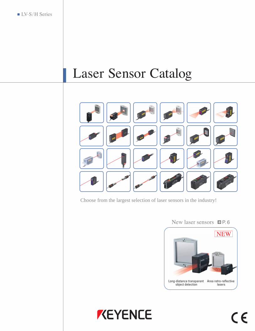
Product composition
Laser sensor features
The LV Series are digital laser sensors consisting of both a sensor head and an amplifier.Please note that the supported amplifier unit depends on the sensor head.
• Compact size • Transparent object detection (available) • Zero datum function (available)
• High-power • Waterproof (available)
• 0.39"/1.18" 10 mm/30 mm area • Analog output
Reflective/Retro-Reflective
Thrubeam
LV-S Series
LV-H Series
LV-H Series
Visible beam allows for easy installation
Stable target detection froma remote location
Small beam spot ensures high precision
Sensor head
LV-11SBLV-12SB
Amplifier
Sensor head
LV-21ALV-22ALV-20A
Amplifier
Sensor head
LV-51MLV-52
Amplifier
NEWNEW
3
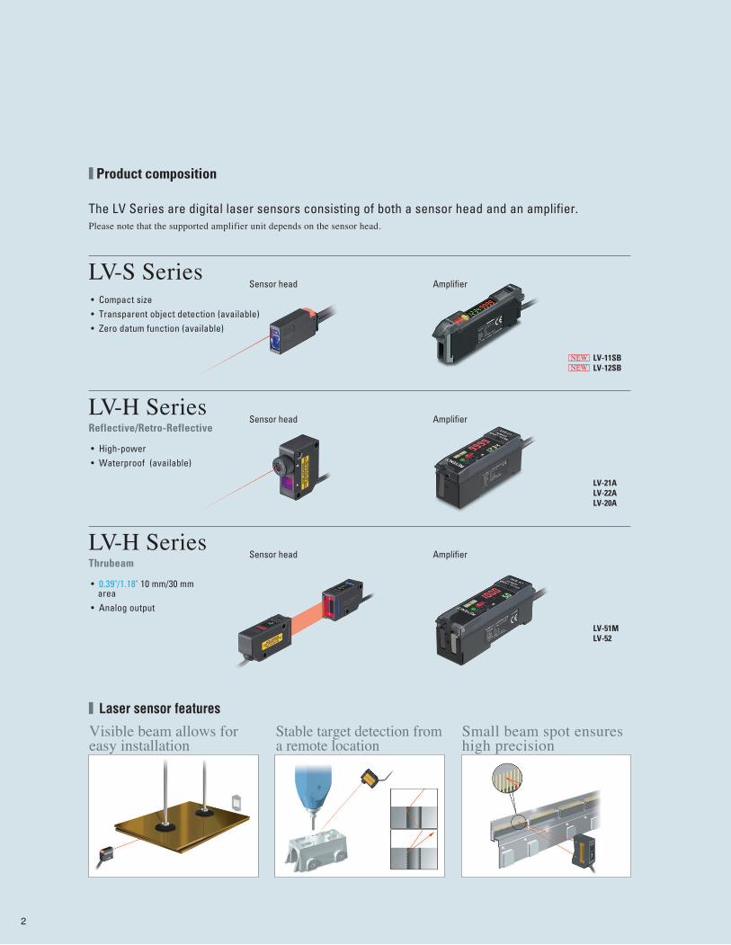
Step1
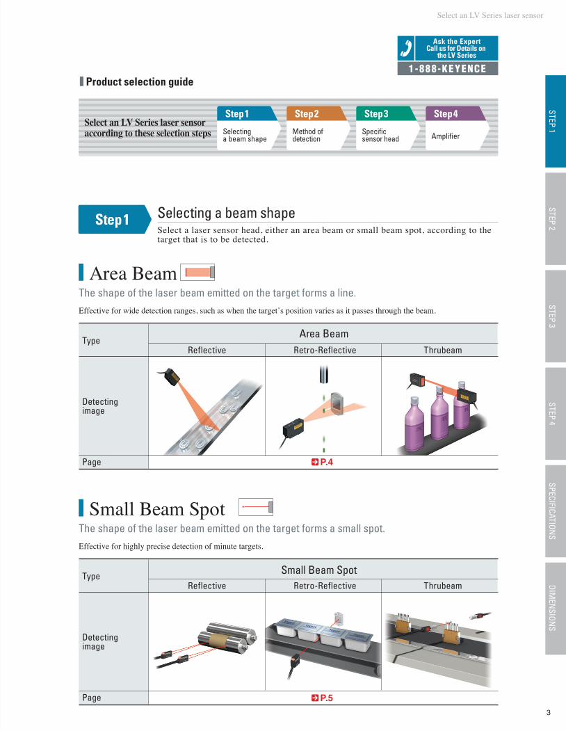
Selecting a beam shape
Step2
Method of detection
Step3
Specific sensor head
Step4
Amplifier
Select an LV Series laser sensor
Select an LV Series laser sensor according to these selection steps
STEP 1STEP 2
STEP 3STEP 4
SPECIFICATIONS
DIMEN
SIONS
Effective for wide detection ranges, such as when the target’s position varies as it passes through the beam.
Small Beam Spot
Effective for highly precise detection of minute targets.
Area Beam
The shape of the laser beam emitted on the target forms a small spot.
The shape of the laser beam emitted on the target forms a line.
Type Small Beam SpotRetro-ReflectiveReflective Thrubeam
Detectingimage
Page P.5
TypeArea Beam
Retro-ReflectiveReflective Thrubeam
Detectingimage
Page P.4
Product selection guide
Ask the ExpertCall us for Details on
the LV Series
1-888-KEYENCE
Step1 Selecting a beam shapeSelect a laser sensor head, either an area beam or small beam spot, according to the target that is to be detected.
4
LV-H64 LV-H65LV-S62 LV-S63
NEW NEW NEW NEW
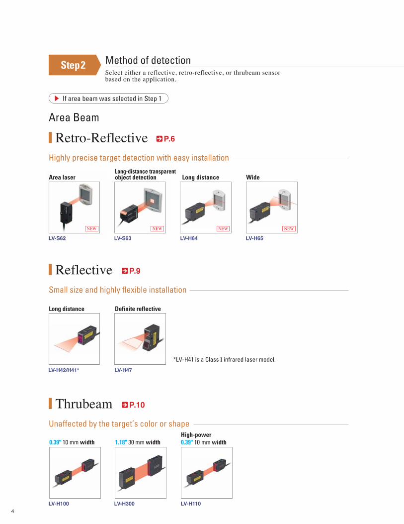
Method of detectionSelect either a reflective, retro-reflective, or thrubeam sensor based on the application.
Area Beam
Small size and highly flexible installation
Reflective
Highly precise target detection with easy installation
Retro-Reflective
Unaffected by the target’s color or shape
Thrubeam
P.9
P.10
If area beam was selected in Step 1
Long distance Definite reflective
Long distance Wide
LV-H100 LV-H300 LV-H110
0.39" 10 mm widthHigh-power 0.39" 10 mm width1.18" 30 mm width
LV-H42/H41*
Area laserLong-distance transparent object detection
Step2
P.6
*LV-H41 is a Class Ⅰ infrared laser model.
LV-H47
5
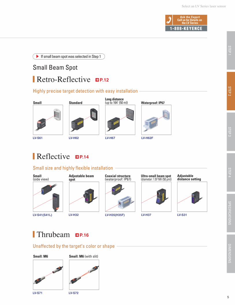
Small Beam Spot
If small beam spot was selected in Step 1
Small size and highly flexible installation
Reflective
LV-S41(S41L)
Retro-Reflective
Unaffected by the target’s color or shape
Thrubeam
Small StandardLong distance (up to 164' (50 m)) Waterproof: IP67
LV-S71 LV-S72
LV-S61 LV-H62 LV-H67 LV-H62F
LV-H32 LV-H35(H35F) LV-H37 LV-S31
P.14
Small: M6 Small: M6 (with slit)
P.12
P.16
Adjustable beam spot
Adjustabledistance setting
Small(side view)
Coaxial structure(waterproof: IP67)
Ultra-small beam spot(diameter: 1.97 Mil (50 µm))
STEP 1STEP 3
STEP 4SPECIFICATION
SDIM
ENSION
SSTEP 2
Select an LV Series laser sensor
Ask the ExpertCall us for Details on
the LV Series
1-888-KEYENCE
Highly precise target detection with easy installation
6
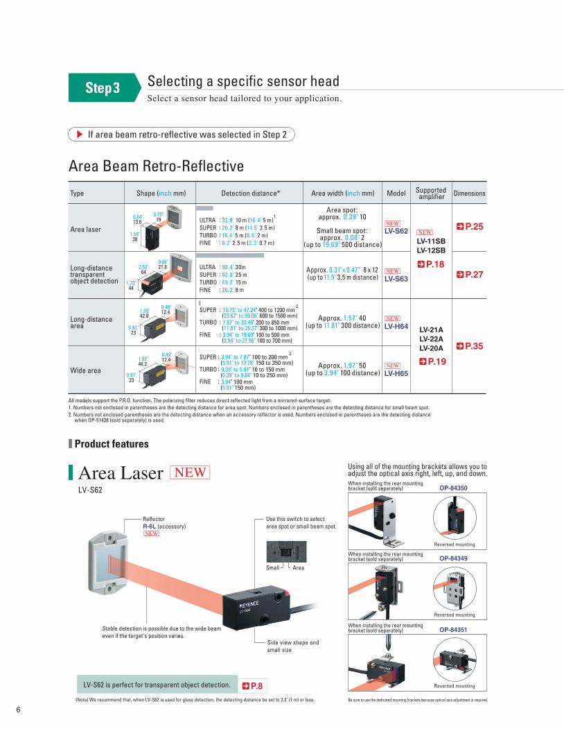
Area Beam Retro-Reflective
If area beam retro-reflective was selected in Step 2
Area LaserLV-S62
Long-distance area
Wide area
LV-H64
LV-H65
LV-S62
LV-S63
Approx. 1.57" 40 (up to 11.81" 300 distance)
Approx. 1.97" 50 (up to 3.94" 100 distance)
P.35
P.19
P.8
Type Shape (inch mm) ModelDetection distance* Area width (inch mm) Supported amplifier Dimensions
LV-21ALV-22ALV-20A
SUPER
TURBO
FINE
: 15.75" to 47.24" 400 to 1200 mm (23.62" to 59.06" 600 to 1500 mm): 7.87" to 33.46" 200 to 850 mm (11.81" to 39.37" 300 to 1000 mm): 3.94" to 19.69" 100 to 500 mm (3.94" to 27.56" 100 to 700 mm)
SUPER
TURBO
FINE
: 3.94" to 7.87" 100 to 200 mm (5.91" to 13.78" 150 to 350 mm): 0.39" to 5.91" 10 to 150 mm (0.39" to 9.84" 10 to 250 mm): 3.94" 100 mm (5.91" 150 mm)
Area spot: approx. 0.39" 10
Small beam spot: approx. 0.08" 2
(up to 19.69" 500 distance)
Approx. 0.31"x 0.47“ 8 x 12 (up to 11.5' 3.5 m distance)
P.25
P.18P.27
LV-11SBLV-12SB
ULTRASUPERTURBOFINE
: 32.8' 10 m (16.4' 5 m): 26.2' 8 m (11.5' 3.5 m): 16.4' 5 m (6.6' 2 m): 8.2' 2.5 m (2.3' 0.7 m)
ULTRASUPERTURBOFINE
: 98.4' 30m: 82.0' 25 m: 49.2' 15 m: 26.2' 8 m
1.69"42.8
0.49"12.4
All models support the P.R.O. function. The polarizing filter reduces direct reflected light from a mirrored-surface target.1. Numbers not enclosed in parentheses are the detecting distance for area spot. Numbers enclosed in parentheses are the detecting distance for small beam spot.2. Numbers not enclosed parentheses are the detecting distance when an accessory reflector is used. Numbers enclosed in parentheses are the detecting distance when OP-51428 (sold separately) is used.
(Note) We recommend that, when LV-S62 is used for glass detection, the detecting distance be set to 3.3' (1 m) or less.
0.91"23
1.82"46.2
0.49"12.4
0.91"23
When installing the rear mountingbracket (sold separately)
Using all of the mounting brackets allows you to adjust the optical axis right, left, up, and down.
Reversed mounting
Area laser
Long-distance transparent object detection
0.54"13.6
0.75"19
1.50"38
2.52"64
0.86"21.8
1.73"44
NEWOP-84350
When installing the rear mountingbracket (sold separately) OP-84349
When installing the rear mountingbracket (sold separately) OP-84351Stable detection is possible due to the wide beam
even if the target's position varies.
Use this switch to select area spot or small beam spot.
AreaSmall
Be sure to use the dedicated mounting brackets because optical axis adjustment is required.
Side view shape and small size
LV-S62 is perfect for transparent object detection.
ReflectorR-6L (accessory)
1.
2.
2.
Product features
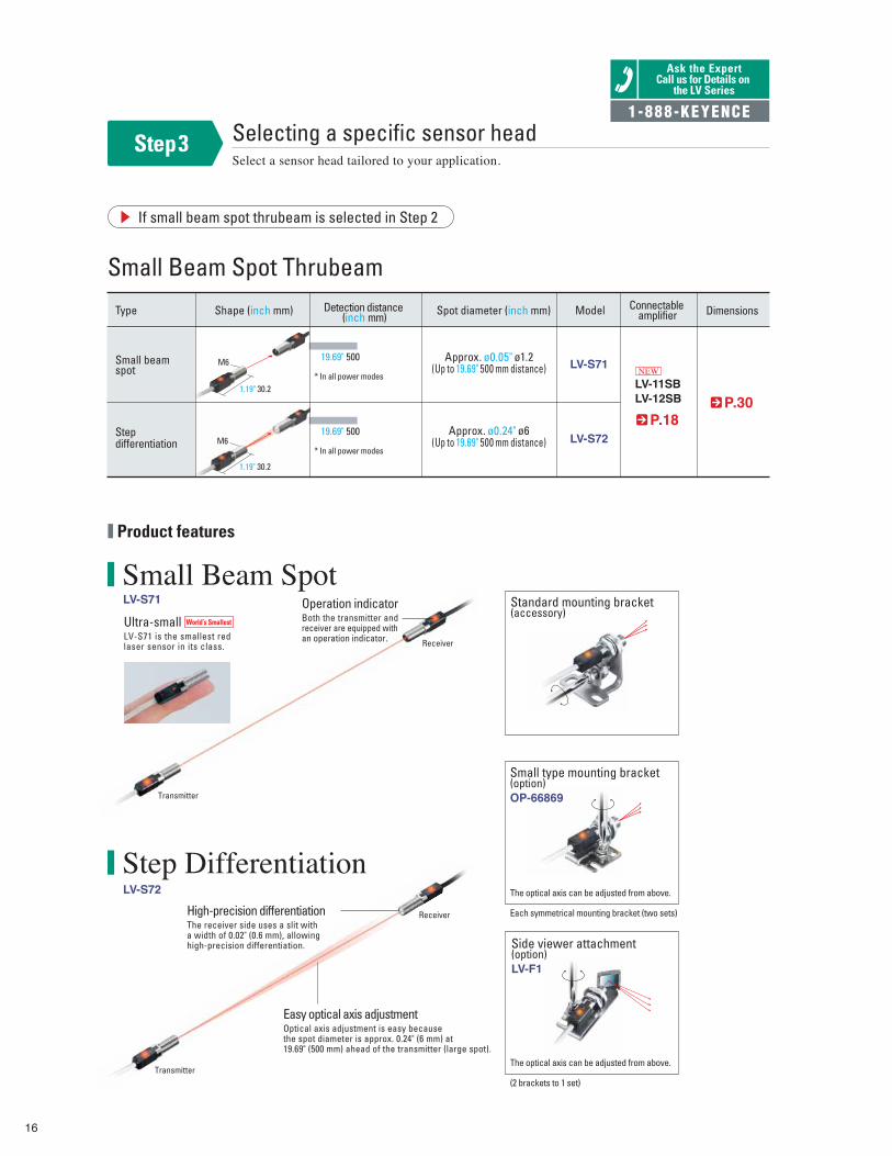
Step3 Selecting a specific sensor headSelect a sensor head tailored to your application.
Reversed mounting
Reversed mounting
NEW
NEW
NEW
NEW
NEW
NEW
7
Ask the ExpertCall us for Details on
the LV Series
The beam shining on a target is clearly visible.
Reflector R-6 grey(accessory)
Reflector R-6 grey(accessory)
Options
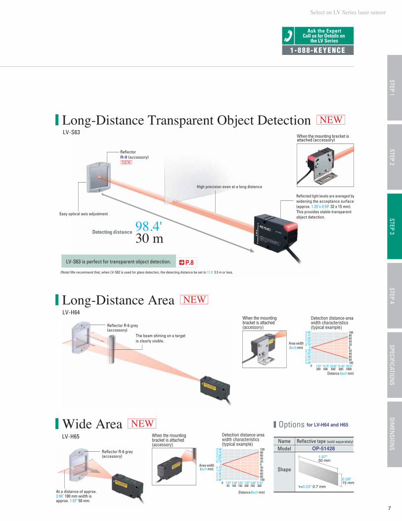
Long-Distance Area
Wide Area
Long-Distance Transparent Object DetectionLV-S63
LV-H64
LV-H65
3.94"3.15"2.36"1.57"0.79"
0 0.79"1.57"2.36"3.15"3.94"
10080604020020406080100
Distance (inch mm)
0 7.87"200
15.75"400
23.62"600
31.50"800
39.37"1000
Detection distance-area width characteristics (typical example)
Area width(inch mm)
3.94"3.15"2.36"1.57"0.79"
0 0.79"1.57"2.36"3.15"3.94"
10080604020020406080100
0 1.97"50
3.94"100
5.91"150
7.87"200
9.84"250
11.81"300
Name Reflective tape (sold separately)
Model
Shape
OP-51428
0.59"15 mm
t=0.03" 0.7 mm
1.97"50 mm
At a distance of approx. 3.94" 100 mm width is approx. 1.97" 50 mm.
NEW
Reflected light levels are averaged by widening the acceptance surface (approx. 1.26"x 0.59" 32 x 15 mm). This provides stable transparent object detection.
Easy optical axis adjustment
High precision even at a long distance
Detecting distance 98.4'30 m
ReflectorR-9 (accessory)
1-888-KEYENCE
for LV-H64 and H65
P.8(Note) We recommend that, when LV-S62 is used for glass detection, the detecting distance be set to 11.5' 3.5 m or less.
LV-S63 is perfect for transparent object detection.
Area width(inch mm)
Distance (inch mm)
NEW
NEW
STEP 1STEP 3
STEP 4SPECIFICATION
SDIM
ENSION
SSTEP 2
When the mounting bracket is attached (accessory)
Detection distance-area width characteristics (typical example)
When the mounting bracket is attached (accessory)
When the mounting bracket is attached (accessory)
Select an LV Series laser sensor
NEW
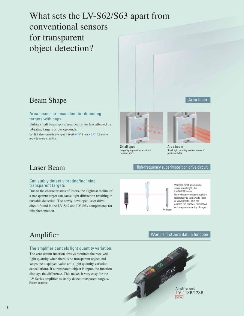
What sets the LV-S62/S63 apart from conventional sensors for transparent object detection?
Area laserBeam Shape
Area beams are excellent for detecting targets with gaps.
Small spotLarge light quantity variation if position shifts
Area beamSmall light quantity variation even if position shifts
Unlike small beam spots, area beams are less affected by vibrating targets or backgrounds.
LV-S63 also spreads the spot’s depth 0.31" 8 mm x 0.47" 12 mm to provide more stability.
High-frequency superimposition drive circuitLaser Beam
The amplifier cancels light quantity variation.The zero datum function always monitors the received light quantity when there is no transparent object and keeps the displayed value at 0 (light quantity variation cancellation). If a transparent object is input, the function displays the difference. This makes it very easy for the LV Series amplifier to stably detect transparent targets.
Can stably detect vibrating/inclining transparent targetsDue to the characteristics of lasers, the slightest incline of a transparent target can cause light diffraction resulting in unstable detection. The newly-developed laser drive circuit found in the LV-S62 and LV-S63 compensates for this phenomenon.
World‘s first zero datum functionAmplifier
Whereas most lasers use a single wavelength, the LV-S62/S63 uses high-frequency superimposition technology to take a wide range of wavelengths. This has enabled the practical elimination of transparent quantity changes.
LV-11SB/12SBAmplifier unit
NEW
(Patent pending)
Reflector
8
STEP 1STEP 3
STEP 4SPECIFICATION
SDIM
ENSION
SSTEP 2
Ask the ExpertCall us for Details on
the LV Series
Step3 Selecting a specific sensor headSelect a sensor head tailored to your application.
1-888-KEYENCE
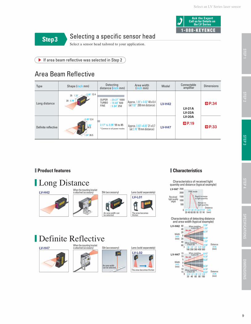
Area Beam Reflective
If area beam reflective was selected in Step 2
* Common in all power modes
P.19
Long distance
Definite reflective
LV-H42
LV-H47
LV-21ALV-22ALV-20A
SUPERTURBOFINE
: 39.37" 1000: 19.69" 500: 9.84" 250
2.17" to 3.35" 55 to 85
P.34
P.33
Type Shape (inch mm) Area width(inch mm) Model Connectable
amplifier Dimensions
1.38" 0.49"
0.79"
12.4
26.5
34.5
Approx. 1.89" x 0.02" 48 x 0.4 (at 7.87" 200 mm distance)
Approx. 0.83" x 0.03" 21 x 0.7 (at 2.76" 70 mm distance)
Detecting distance (inch mm)
20
35 12.4
0.49"
1.36"
1.04"
Characteristics
4003002001000
604020
0204060
No slit
When installinga black slit
When installinga grey slit
500
LV-H47
LV-H47
LV-H42
25002000
15001000
500
020 40 60 80 100
Received light quality
(digit)
120 140
Characteristics of received light quantity and distance (typical example)
Characteristics of detecting distance and area width (typical example)
FINE mode
Rapid increase in light quantity
Almost no light quantity
806040200
Distanceinch(mm)
Distanceinch(mm)
1510
505
1015
100
Widthinch(mm)
Widthinch(mm)
No slit
When installinga black slit
When installinga grey slit
0.79" 1.57" 2.36" 3.15" 3.94" 4.72" 5.51"
15.75"1.81"7.87"3.94" 19.69"
0.79" 1.57" 2.36" 3.15" 3.94"
2.36"1.57"0.79"
0.79"1.57"2.36"
0.43"0.39"0.20"
0.20"0.39"0.43"
Product features
Long Distance
Definite Reflective
LV-H42LV-L01
LV-L02LV-H47
An area width can be selected.
An area width can be selected.
The area becomes thicker.
Slit (accessory) Lens (sold separately)
The area becomes thicker.
Slit (accessory) Lens (sold separately)
When the mounting bracket is attached (accessory)
When the mounting bracket is attached (accessory)
Select an LV Series laser sensor
9
Distanceinch(mm)
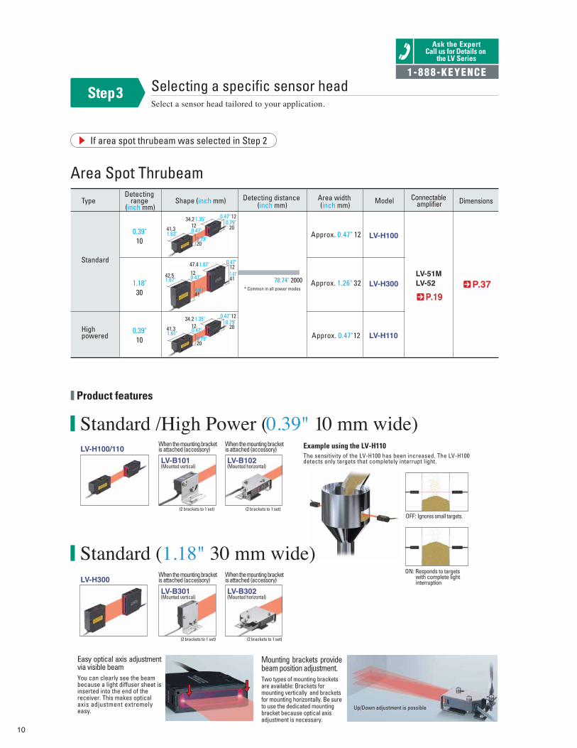
Standard /High Power (0.39" 10 mm wide)
Standard
High powered
LV-H100
LV-H300LV-51MLV-52
LV-H110
LV-B101(Mounted vertical)
LV-B102(Mounted horizontal)
LV-B301(Mounted vertical)
LV-B302(Mounted horizontal)
Approx. 0.47" 12
Approx. 1.26" 32
Approx. 0.47"12
78.74" 2000* Common in all power modes P.37
P.19
Type
0.39"10
1.18"30
0.39"10
Detecting range
(inch mm)Detecting distance
(inch mm) Model
OFF: Ignores small targets.
ON: Responds to targets with complete light interruption
(2 brackets to 1 set) (2 brackets to 1 set)
Area width (inch mm)
12
2034.2
12
20
41.3
Shape (inch mm)
1247.4
41
42.5
12
2034.2
12
20
41.3
Example using the LV-H110The sensitivity of the LV-H100 has been increased. The LV-H100detects only targets that completely interrupt light.
Up/Down adjustment is possible
Easy optical axis adjustment via visible beamYou can clearly see the beam because a light diffuser sheet is inserted into the end of the receiver. This makes optical axis adjustment extremely easy.
Mounting brackets provide beam position adjustment.Two types of mounting brackets are available: Brackets for mounting vertically and brackets for mounting horizontally. Be sure to use the dedicated mounting bracket because optical axis adjustment is necessary.
Connectable amplifier Dimensions
LV-H100/110
Standard (1.18" 30 mm wide)LV-H300
When the mounting bracketis attached (accessory)
When the mounting bracketis attached (accessory)
When the mounting bracketis attached (accessory)
When the mounting bracketis attached (accessory)
1.63" 0.47"0.79"
0.79"0.47"1.35"
1.67"120.47"
0.47"1.87"
1.61"
411.61"
0.47"
0.47"1.61"0.79"
0.79"1.35"
Area Spot Thrubeam
Step3 Selecting a specific sensor headSelect a sensor head tailored to your application.
Product features
Ask the ExpertCall us for Details on
the LV Series
1-888-KEYENCE
10
(2 brackets to 1 set) (2 brackets to 1 set)
If area spot thrubeam was selected in Step 2
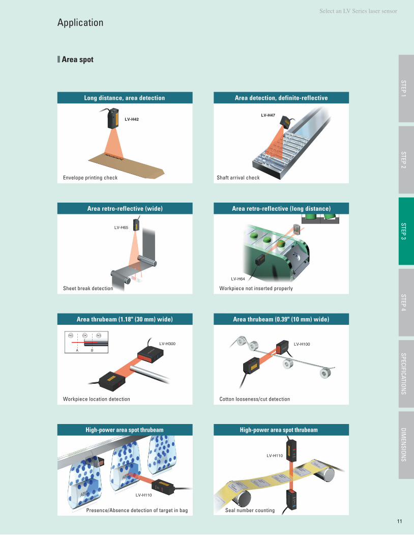
Application
Long distance, area detection
Envelope printing check
Area retro-reflective (wide)
Sheet break detection
Area detection, definite-reflective
Shaft arrival check
Area retro-reflective (long distance)
Workpiece not inserted properly
LV-H42LV-H47
LV-H65
LV-H64
Area spot
High-power area spot thrubeam
Presence/Absence detection of target in bag
High-power area spot thrubeam
Seal number counting
Select an LV Series laser sensor STEP 1
STEP 3STEP 4
SPECIFICATIONS
DIMEN
SIONS
STEP 2
11
Area thrubeam (1.18" (30 mm) wide)
Workpiece location detection
Area thrubeam (0.39" (10 mm) wide)
Cotton looseness/cut detection
A B
NG OK NG
LV-H300 LV-H100
LV-H110
LV-H110
12
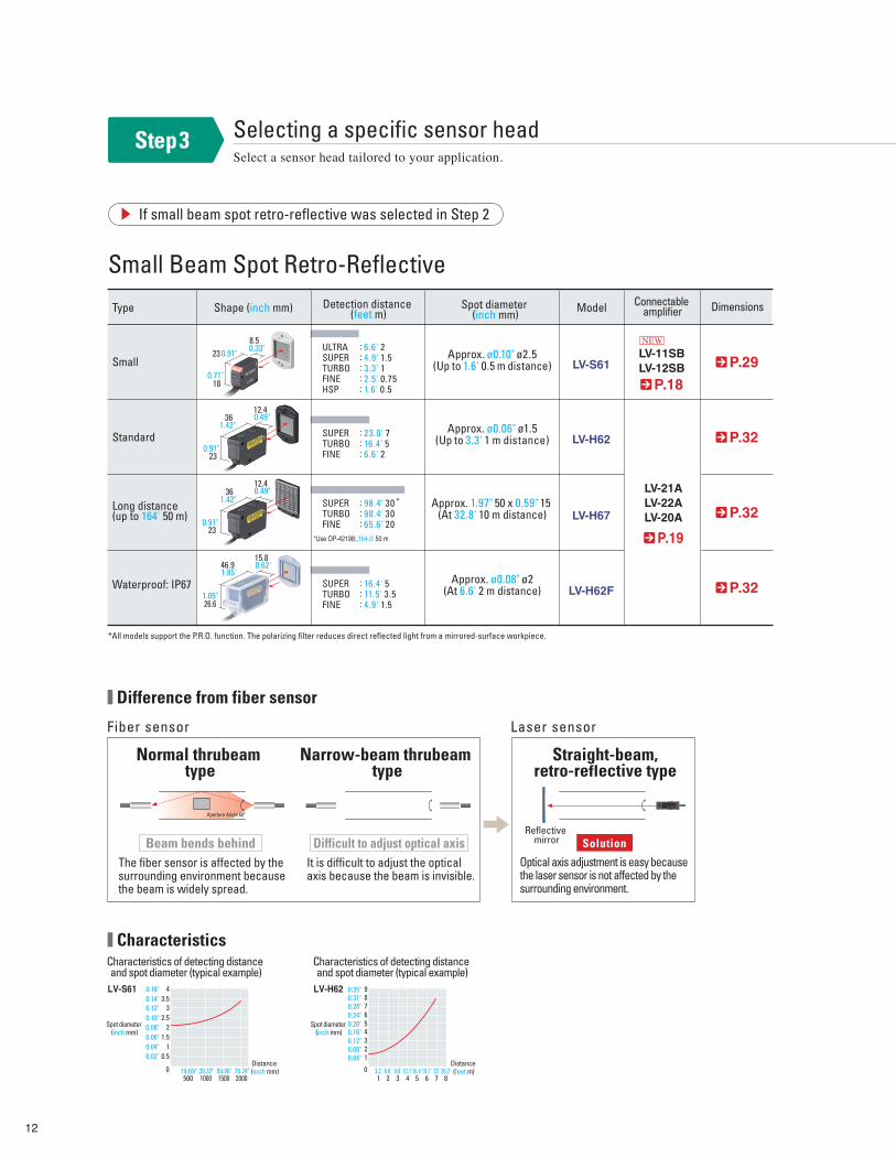
Step3 Selecting a specific sensor headSelect a sensor head tailored to your application.
Small Beam Spot Retro-Reflective
If small beam spot retro-reflective was selected in Step 2
Difference from fiber sensor
Characteristics
Standard
Small
Long distance (up to 164' 50 m)
Waterproof: IP67
LV-S61
LV-H62
LV-11SBLV-12SB
LV-21ALV-22ALV-20ALV-H67
LV-H62F
Approx. ø0.10" ø2.5(Up to 1.6' 0.5 m distance)
ULTRASUPERTURBOFINEHSP
: 6.6' 2: 4.9' 1.5: 3.3' 1: 2.5' 0.75: 1.6' 0.5
SUPERTURBOFINE
: 98.4' 30: 98.4' 30: 65.6' 20
SUPERTURBOFINE
: 16.4' 5: 11.5' 3.5: 4.9' 1.5
SUPERTURBOFINE
: 23.0' 7: 16.4' 5: 6.6' 2
*Use OP-42198:,164.0' 50 m
*All models support the P.R.O. function. The polarizing filter reduces direct reflected light from a mirrored-surface workpiece.
Approx. ø0.06" ø1.5(Up to 3.3' 1 m distance)
Approx. 1.97" 50 x 0.59" 15 (At 32.8' 10 m distance)
Approx. ø0.08" ø2(At 6.6' 2 m distance)
P.29
P.18
P.19
P.32
P.32
P.32
Type Shape (inch mm) Detection distance (feet m)
Connectable amplifierSpot diameter
(inch mm) Model Dimensions
46.915.8
26.6
Fiber sensor Laser sensor
3612.4
23
238.5
18
Normal thrubeam type
Narrow-beam thrubeam type
Straight-beam,retro-reflective type
Reflective mirror
The fiber sensor is affected by the surrounding environment because the beam is widely spread.
It is difficult to adjust the optical axis because the beam is invisible.
Optical axis adjustment is easy because the laser sensor is not affected by the surrounding environment.
Aperture Angle 60°
SolutionBeam bends behind Difficult to adjust optical axis
Characteristics of detecting distance and spot diameter (typical example)
Distance (inch mm)
Characteristics of detecting distance and spot diameter (typical example)
78.74"59.06"39.37"19.69"
0.51
1.52
2.53
3.54
Spot diameter (inch mm)
LV-S61 LV-H62
Distance (feet m)3.3' 6.6' 9.8' 13.1'16.4'19.7' 23' 26.2'
123456789
Spot diameter (inch mm)
*
0.33"0.91"
0.71"
0.49"1.42"
0.91"
12.40.49"36
1.42"
230.91"
0.62'1.85'
1.05"
0.02"0.04"0.06"0.08"0.10"0.12"0.14"0.16"
200015001000500
0.04"0.08"0.12"0.16"0.20"0.24"0.28"0.31"0.35"
1 2 3 4 5 6 7 80 0
NEW
13
Select an LV Series laser sensor
Ask the ExpertCall us for Details on
the LV Series
1-888-KEYENCE
STEP 1STEP 3
STEP 4SPECIFICATION
SDIM
ENSION
SSTEP 2
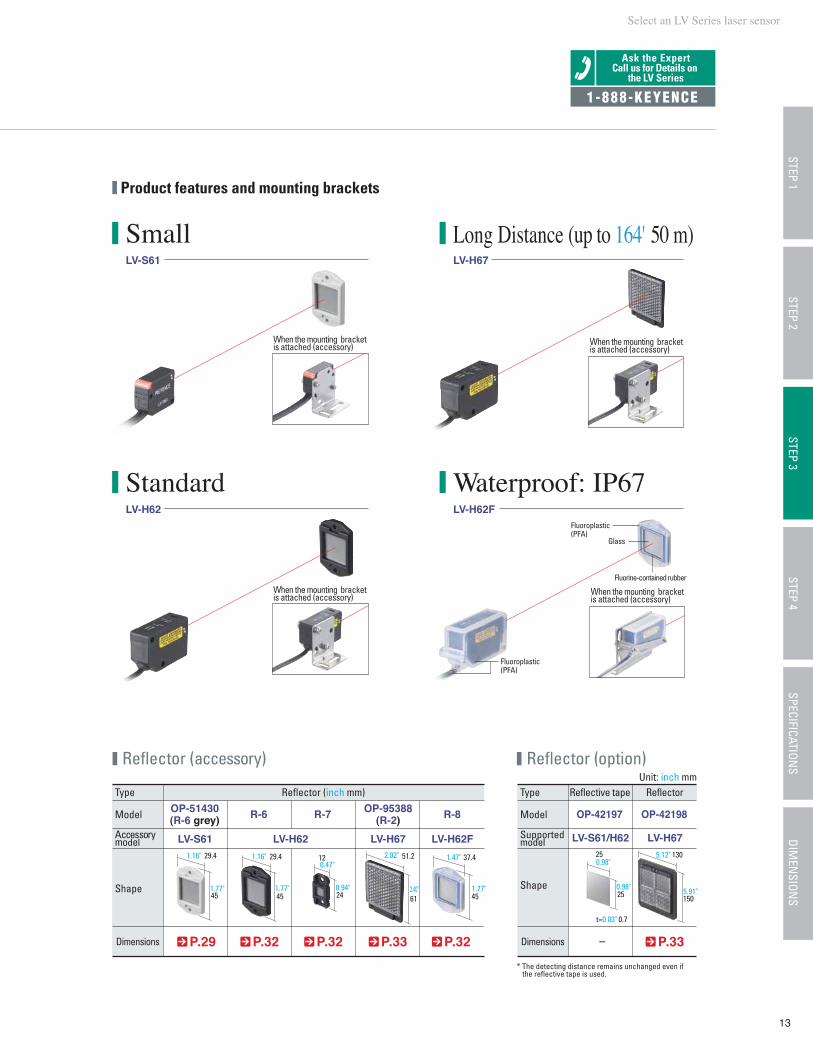
Small Long Distance (up to 164' 50 m)
Product features and mounting brackets
* The detecting distance remains unchanged even if the reflective tape is used.
P.29
LV-S61 LV-H67
45
StandardLV-H62
Waterproof: IP67LV-H62F
Type Reflector (inch mm) Reflective tape Reflector
Model
Accessory model
Shape
Dimensions P.32 P.32 P.33 P.32
LV-S61 LV-H62 LV-H67 LV-H62F LV-S61/H62 LV-H67
OP-51430(R-6 grey)
OP-95388(R-2)
Type
Model
Supported model
Shape
– P.33
OP-42197 OP-42198R-6 R-7 R-8
45
29.4
45
37.4
61
51.2
24
12
25
t=0.03" 0.7
25
150
130
Glass
Fluorine-contained rubber
Fluoroplastic(PFA)
Fluoroplastic(PFA)
When the mounting bracket is attached (accessory)
When the mounting bracket is attached (accessory)
Reflector (accessory) Reflector (option)
Dimensions
When the mounting bracket is attached (accessory)
When the mounting bracket is attached (accessory)
Unit: inch mm
1.16" 29.41.16"
1.77" 1.77"
0.47"
0.94"
2.02"
2.40"
1.47"
1.77"
0.98"
0.98"
5.12"
5.91"
14
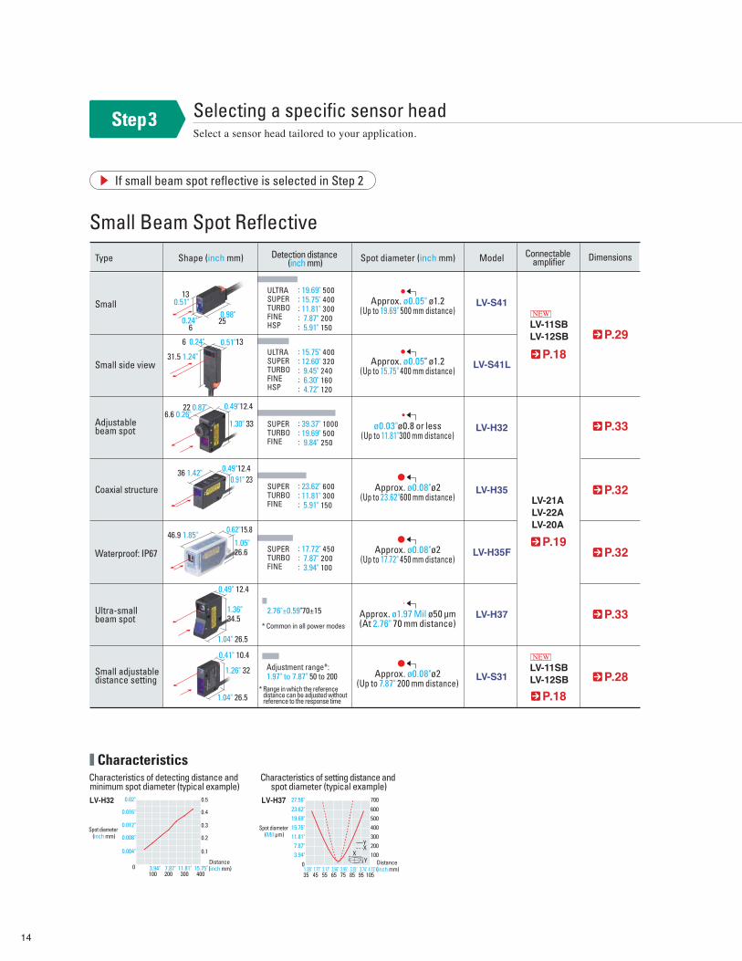
Small Beam Spot Reflective
Selecting a specific sensor headSelect a sensor head tailored to your application.
If small beam spot reflective is selected in Step 2
Step3
CharacteristicsCharacteristics of setting distance and
spot diameter (typical example)
Spot diameter (Mil µm)
2.95"2.56"2.17"1.77"1.38"Distance (inch mm)
600
700
500400300200100
03.35" 3.74" 4.13"
YX
XYDistance
(inch mm)
Characteristics of detecting distance and minimum spot diameter (typical example)
0.5
0.4
0.3
0.2
0.1
0 3.94" 7.87"
Spot diameter (inch mm)
LV-H32 LV-H37
LV-S41
LV-S41L
LV-11SBLV-12SB
LV-21ALV-22ALV-20A
LV-H32
LV-H35
LV-H35F
LV-H37
LV-S31
ULTRASUPERTURBOFINEHSP25
0.51"
13
0.49"12.4
0.49"12.4
0.49" 12.4
0.41" 10.4
0.91" 23
1.30" 33
22 0.87"
36 1.42"
46.9 1.85" 0.62"15.8
1.05"26.6
1.36"34.5
1.04" 26.5
1.04" 26.5
1.26" 32
6.6 0.26"
6
: 19.69" 500: 15.75" 400: 11.81" 300: 7.87" 200: 5.91" 150
ULTRASUPERTURBOFINEHSP
: 15.75" 400: 12.60" 320: 9.45" 240: 6.30" 160: 4.72" 120
SUPERTURBOFINE
: 39.37" 1000: 19.69" 500: 9.84" 250
SUPERTURBOFINE
: 23.62" 600: 11.81" 300: 5.91" 150
SUPERTURBOFINE
2.76"±0.59"70±15
* Common in all power modes
Adjustment range*: 1.97" to 7.87" 50 to 200
* Range in which the reference distance can be adjusted without reference to the response time
: 17.72" 450: 7.87" 200: 3.94" 100
P.29
P.18
P.19
P.33
P.32
P.32
P.33
P.28
Type Shape (inch mm) Detection distance (inch mm) Spot diameter (inch mm) Model
Small
Coaxial structure
Waterproof: IP67
Small side view
Adjustable beam spot
Ultra-small beam spot
Small adjustable distance setting
Connectable amplifier Dimensions
31.5 1.24"
ø0.03"ø0.8 or less(Up to 11.81"300 mm distance)
Approx. ø0.08"ø2(Up to 17.72" 450 mm distance)
Approx. ø1.97 Mil ø50 µm(At 2.76" 70 mm distance)
Approx. ø0.05" ø1.2(Up to 19.69" 500 mm distance)
Approx. ø0.05" ø1.2(Up to 15.75" 400 mm distance)
Approx. ø0.08"ø2(Up to 23.62"600 mm distance)
Approx. ø0.08"ø2(Up to 7.87" 200 mm distance)
13
0.51"
0.24"0.98"
0.24"6
0.02"
0.016"
0.012"
0.008"
0.004"
40030020010011.81" 15.75"
23.62"
27.56"
19.69"15.75"11.81"
7.87"3.94"
75655545 85 95 10535
NEW
LV-11SBLV-12SB
P.18
NEW
Select an LV Series laser sensor
15
STEP 1STEP 3
STEP 4SPECIFICATION
SDIM
ENSION
SSTEP 2
Ask the ExpertCall us for Details on
the LV Series
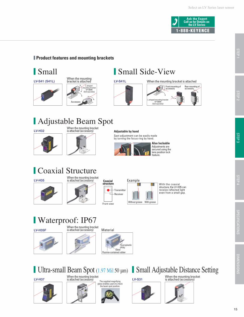
Small Small Side-View
Small Adjustable Distance Setting
Adjustable Beam Spot
Coaxial Structure
Waterproof: IP67
Ultra-small Beam Spot (1.97 Mil 50 μm)
1-888-KEYENCE
Also lockableAdjustments are secured using the lens position lock feature.
With the coaxial structure, the LV-H35 can receive reflected light even from a small gap.
Coaxial structure
Front view
Transmitter
Receiver
Without grease With grease
LV-S41 (S41L) LV-S41L
LV-H32
LV-H35
LV-H35F
LV-H37 LV-S31
Material
Example
Accessory
Front mounting of accessory
Rear mounting of accessory
L-shaped mounting bracket
OP-66846(Sold separately)
L-shaped mounting bracketOP-66846
(Sold separately)
Adjustable by handSpot adjustment can be easily madeby turning the focus ring by hand.
GlassFluorine-contained rubber
Fluoroplastic(PFA)
Product features and mounting brackets
When the mounting bracket is attached
When the mounting bracket is attached (accessory)
When the mounting bracket is attached (accessory)
When the mounting bracket is attached (accessory)
When the mounting bracket is attached (accessory)
When the mounting bracket is attached (accessory)
When the mounting bracket is attached
The supplied magnifying glass enables users to check
the beam spot position.
16
Small Beam Spot Thrubeam
Selecting a specific sensor headSelect a sensor head tailored to your application.
If small beam spot thrubeam is selected in Step 2
Each symmetrical mounting bracket (two sets)
(2 brackets to 1 set)
Step3
Product features
LV-S71
LV-S72
19.69" 500
* In all power modes
19.69" 500
* In all power modes
P.30
Small beam spot
Step differentiation
Shape (inch mm)Type Detection distance (inch mm) Spot diameter (inch mm) Model
Small Beam SpotLV-S71
Step DifferentiationLV-S72
1.19" 30.2
M6
1.19" 30.2
M6
High-precision differentiationThe receiver side uses a slit with a width of 0.02" (0.6 mm), allowing high-precision differentiation.
Easy optical axis adjustmentOptical axis adjustment is easy because the spot diameter is approx. 0.24" (6 mm) at 19.69" (500 mm) ahead of the transmitter (large spot).
Small type mounting bracket (option)OP-66869
The optical axis can be adjusted from above.
Side viewer attachment (option) LV-F1
Standard mounting bracket (accessory)
The optical axis can be adjusted from above.
Operation indicatorBoth the transmitter and receiver are equipped with an operation indicator.
Ultra-smallLV-S71 is the smallest red laser sensor in its class.
Transmitter
Transmitter
Receiver
Receiver
World’s Smallest
Connectable amplifier Dimensions
Approx. ø0.05" ø1.2(Up to 19.69" 500 mm distance)
Approx. ø0.24" ø6(Up to 19.69" 500 mm distance)
Ask the ExpertCall us for Details on
the LV Series
1-888-KEYENCE
LV-11SBLV-12SB
P.18
NEW
Select an LV Series laser sensor
17
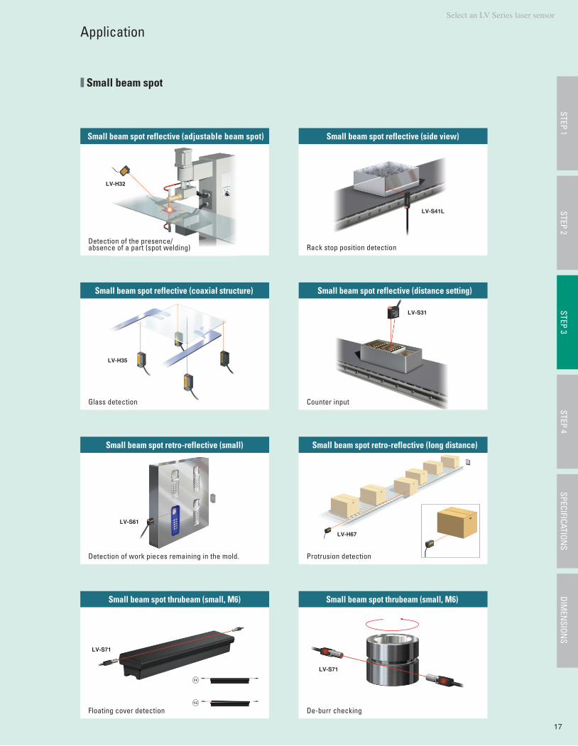
Small beam spot reflective (adjustable beam spot)
Detection of the presence/absence of a part (spot welding)
Small beam spot reflective (coaxial structure)
Glass detection
Small beam spot retro-reflective (small)
Detection of work pieces remaining in the mold.
Small beam spot thrubeam (small, M6)
Floating cover detection
Small beam spot reflective (side view)
Rack stop position detection
Small beam spot reflective (distance setting)
Counter input
Small beam spot retro-reflective (long distance)
Protrusion detection
Small beam spot thrubeam (small, M6)
De-burr checkingNG
OK
LV-H32
LV-S41L
LV-H35
LV-S31
LV-S61
LV-S71
LV-S71
LV-H67
Small beam spot
ApplicationSTEP 1
STEP 3STEP 4
SPECIFICATIONS
DIMEN
SIONS
STEP 2
18
If the LV-S Series is selected in Step 3
Usually* the first digit of the digital display will drift when there is no workpiece. The zero datum function* clears the display to 0, eliminating this drifting status. (Returning to the nominal display when light is interrupted)
Popular DSC function
*When the retro-reflective type or thrubeam type is used
(Patent pending)
[Supplement]Datum means reference. Zero datum is a function that changes the light quantity display to 0 when there is no work piece at 0 reference.
Unique form dust cover
Heat sink for stable operation
2 outputs x 2 banks (4 outputs total)
Easily adjustable large manual button
Easy connection connector method
Monitor that can set or show current light intensity values (5-digit or 4-digit display)
Clearly visible bright solid operation indicator
Secure head connection
Quick SET button
Part names and features The LV-S Series, comes with the world’s first zero datum function.
The LV-S Series comes with the DSC function.
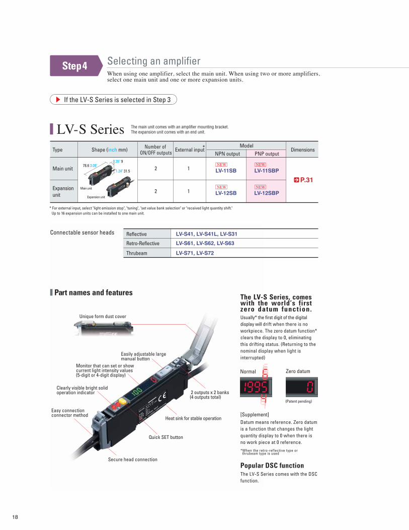
LV-S Series
Main unit
Expansion unit
LV-11SB
LV-12SB
P.31
Type Shape (inch mm) External inputModel
NPN output
Expansion unit
Main unit
2
2
1
1
1.24" 31.578.6 3.09"
0.35" 9
* For external input, select "light emission stop", "tuning", "set value bank selection" or "received light quantity shift." Up to 16 expansion units can be installed to one main unit.
The main unit comes with an amplifier mounting bracket.The expansion unit comes with an end unit.
Connectable sensor heads LV-S41, LV-S41L, LV-S31
LV-S61, LV-S62, LV-S63
Reflective
LV-S71, LV-S72Thrubeam
Retro-Reflective
Normal Zero datum
Number of ON/OFF outputs Dimensions*
Selecting an amplifierWhen using one amplifier, select the main unit. When using two or more amplifiers, select one main unit and one or more expansion units.
Step4
NEW
NEW
PNP output
LV-11SBP
LV-12SBP
NEW
NEW
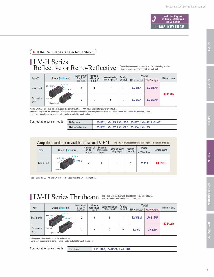
LV-H Series Reflective or Retro-Reflective
Select an LV Series laser sensor
19
STEP 1STEP 3
STEP 4SPECIFICATION
SDIM
ENSION
SSTEP 2
If the LV-H Series is selected in Step 3
Main unit
Expansion unit Expansion unit
Main unit
Expansion unit
Main unit
The main unit comes with an amplifier mounting bracket.The expansion unit comes with an end unit.
The main unit comes with an amplifier mounting bracket.The expansion unit comes with an end unit.
1.12" 28.565.8 2.59"
0.79" 20
Amplifier unit for invisible infrared LV-H41
Connectable sensor heads
LV-21A
LV-H32, LV-H35, LV-H35F, LV-H37, LV-H42, LV-H47
LV-H62, LV-H67, LV-H62F, LV-H64, LV-H65
LV-22A
P.36
2
2
1
0
1
0
0
0
Type*1 Shape (inch mm)
Reflective
Retro-Reflective
*1 The LV-20A is also available to support the zero line. (It does NOT have a cable for power or outputs).*2 external inputs on the expansion units can be used for calibration. However, laser emission stop input cannot be used on the expansion units. Up to seven additional expansion units can be installed for each main unit.
The amplifier unit comes with the amplifier mounting bracket.
P.39
2
2
0
0
1
0
1
0
Type
Main unit
Expansion unit
LV-51M
LV-52
1.12" 28.774.6 2.94"
0.79" 20
*1 Laser emission stop input on the main unit only. Up to seven additional expansion units can be installed for each main unit.
1.12" 28.565.8 2.59"
0.79" 20
Main unit
Main unit LV-11A P.362 1 1 0
Type Shape (inch mm)
Connectable sensor heads LV-H100, LV-H300, LV-H110Thrubeam
(Note) Only the LV-H41 and LV-H51 can be used with the LV-11A amplifier.
Number of ON/OFF outputs
Analogoutput
Laser emission stop input *2
External calibration
input *2Dimensions
LV-H Series Thrubeam
ModelNPN output
Shape (inch mm)Number of
ON/OFF outputs
Analogoutput
Laser emission stop input *1
External calibration
input Dimensions
ModelNPN output
Number of ON/OFF outputs
Analogoutput
Laser emission stop input
External calibration
input Dimensions
ModelNPN output
Ask the ExpertCall us for Details on
the LV Series
1-888-KEYENCE
LV-21AP
LV-22AP
PNP output
LV-51MP
LV-52P
PNP output
20
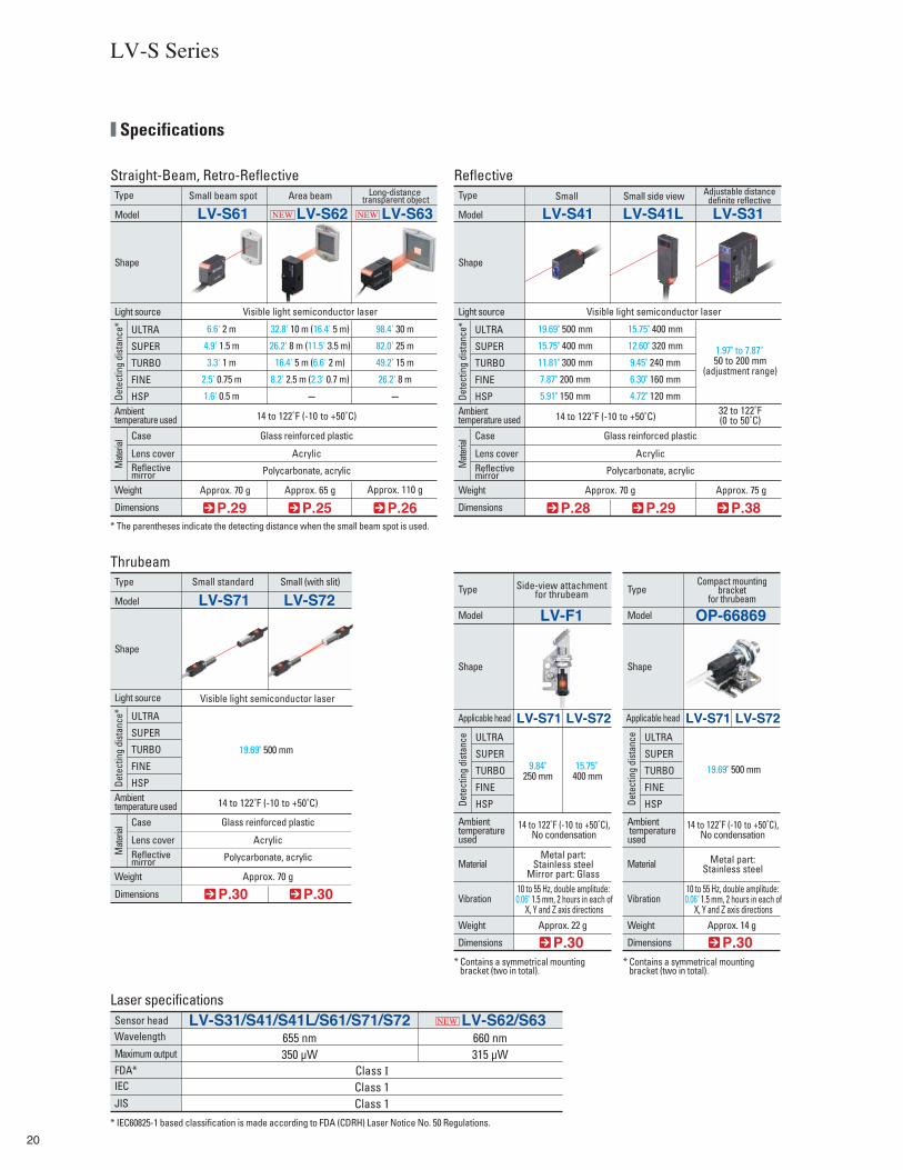
Type Small beam spot Area beam
Visible light semiconductor laser
Long-distance transparent object
Model
Shape
Weight
Dimensions
Ambient temperature used
Light source
Dete
ctin
g di
stan
ce*
Mate
rial
LV-S61 LV-S62 LV-S63
6.6' 2 m 32.8' 10 m (16.4' 5 m) 98.4' 30 m
4.9' 1.5 m 26.2' 8 m (11.5' 3.5 m) 82.0' 25 m
3.3' 1 m 16.4' 5 m (6.6' 2 m) 49.2' 15 m
2.5' 0.75 m 8.2' 2.5 m (2.3' 0.7 m) 26.2' 8 m
1.6' 0.5 m – –
14 to 122˚F (-10 to +50˚C) 14 to 122˚F (-10 to +50˚C)
Glass reinforced plastic
Acrylic
Polycarbonate, acrylic
Approx. 70 g Approx. 65 g Approx. 110 g
P.29 P.25 P.26
LV-S Series
Straight-Beam, Retro-Reflective
TURBO
FINE
HSP
SUPER
ULTRA
Reflective mirror
Lens cover
Case
Type Small standard Small (with slit)
Visible light semiconductor laser
Model
Shape
Weight
Dimensions
Ambient temperature used
Light source
Dete
ctin
g di
stan
ce*
Mate
rial
LV-S71 LV-S72
19.69" 500 mm
Glass reinforced plastic
Acrylic
Polycarbonate, acrylic
Approx. 70 g
P.30 P.30
Thrubeam
TURBO
FINE
HSP
SUPER
ULTRA
Reflective mirror
Lens cover
Case
Sensor headWavelength
Maximum outputFDA*IEC
JIS
LV-S31/S41/S41L/S61/S71/S72 LV-S62/S63655 nm350 µW
Class ⅠClass 1Class 1
660 nm315 µW
Laser specifications
Type
Model
Side-view attachmentfor thrubeam
Ambient temperature used
Material
Vibration
Weight
Applicable head
Dimensions
LV-S71 LV-S72
LV-F1
9.84" 250 mm
15.75" 400 mm
Approx. 22 g
Metal part:Stainless steel
Mirror part: Glass10 to 55 Hz, double amplitude: 0.06" 1.5 mm, 2 hours in each of
X, Y and Z axis directions
Shape
P.30
* IEC60825-1 based classification is made according to FDA (CDRH) Laser Notice No. 50 Regulations.
* The parentheses indicate the detecting distance when the small beam spot is used.
* Contains a symmetrical mounting bracket (two in total).
Type Small Small side view
Visible light semiconductor laser
Adjustable distancedefinite reflective
Model
Shape
Weight
Dimensions
Ambient temperature used
Light source
Dete
ctin
g di
stan
ce*
Mate
rial
LV-S41 LV-S41L LV-S31
19.69" 500 mm 15.75" 400 mm
15.75" 400 mm 12.60" 320 mm
11.81" 300 mm 9.45" 240 mm1.97" to 7.87" 50 to 200 mm
(adjustment range)7.87" 200 mm 6.30" 160 mm
5.91" 150 mm 4.72" 120 mm32 to 122˚F(0 to 50˚C)
Glass reinforced plastic
Acrylic
Polycarbonate, acrylic
Approx. 70 g Approx. 75 g
P.28 P.29 P.38
Reflective
TURBO
FINE
HSP
SUPER
ULTRA
Reflective mirror
Lens cover
Case
Dete
ctin
g di
stan
ce
TURBO
FINE
HSP
SUPER
ULTRA
14 to 122˚F (-10 to +50˚C)
Type
Model
Compact mountingbracket
for thrubeam
Ambient temperature used
Material
Vibration
Weight
Applicable head
Dimensions
LV-S71 LV-S72
OP-66869
19.69" 500 mm
Approx. 14 g
Metal part:Stainless steel
10 to 55 Hz, double amplitude: 0.06" 1.5 mm, 2 hours in each of
X, Y and Z axis directions
Shape
P.30* Contains a symmetrical mounting bracket (two in total).
Dete
ctin
g di
stan
ce
TURBO
FINE
HSP
SUPER
ULTRA
14 to 122˚F (-10 to +50˚C),No condensation
14 to 122˚F (-10 to +50˚C),No condensation
Specifications
NEW NEW
NEW
21
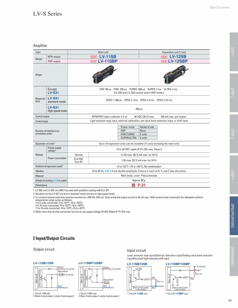
LV-11SB/12SB LV-11SBP/12SBP
Laser emission stop input/External calibration input/Setting value bank selectioninput/Received light intensity shift input
Pink
Brown*
12 to 24 VDC
Blue*Blue1.
Pink
PLC, etc.
PLC, etc.
0 V
3.3 VDC
(Short-circuit current: 1 mA or lower)
(Short-circuit current: 2 mA or lower)
LV-11SB/12SB
Black/white2.
Brown1.
0 V
5 to 40 VDC
12 to 24 VDC 12 to 24 VDC
LV-11SBP/12SBP
Blue1.
Black/white2.
Brown1.
0 V
1. The LV-11SB only2. Black: Control output 1, white: Control output 2
* The LV-11SB only1. The LV-11SBP only2. Black: Control output 1, white: Control output 2
* The LV-11SBP only
Amplifier
Model 1.
Type
LV-11SB LV-12SB
Control output
Control input
Power supply voltage 4.
Power consumptionRatings
Ambient temperature used 3.
Vibration
Material
Weight (including 6.6' 2-m cable)
Dimensions
HSP: 80 µs FINE: 250 µs TURBO: 500 µs SUPER: 2 ms ULTRA: 4 ms (LV-S62 and LV-S63 cannot select HSP mode.)
NPN(PNP) open-collector x 2 ch 40 VDC (30 V) max. 100 mA max. per outputLight emission stop input, external calibration, set value bank selection input, or shift input
10 to 55 Hz, 0.06" 1.5 mm double amplitude: 2 hours in each of X, Y, and Z axis directions
Main body, cover: Polycarbonate
Approx. 80 g
1.5 W max. (62.5 mA max. for 24 V)
1.35 max. (57.3 mA max. for 24 V)
NormalEco-HalfEco-All
12 to 24 VDC ripple (P-P) 10% max. Class 2
14 to 122˚F (-10 to +50˚C), No condensation
NPN output
ExceptLV-S31
LV-S31standard mode
1. LV-S62 and LV-S63 can ONLY be used with amplifiers ending with B or BP.2. Numbers for the LV-S31 are four in standard mode and two in high-speed mode.3. To connect several units they must be mounted on a METAL DIN rail. Ensure that the output current is 20 mA max. With several units connected, the allowable ambient temperature range varies as follows: 1 to 2 units connected: 14 to 131ºF (-10 to +55ºC) 3 to 10 units connected: 14 to 122ºF (-10 to +50ºC) 11 to 16 units connected: 14 to 113ºF (-10 to +45ºC)4. When more than 8 units connected, be sure to use supply voltage 24 VDC Ripple (P-P) 10% max.
Main unit Expansion unit (1 line)
Shape
Response time
250 µsLV-S31High-speed mode
Expansion of units 3. Up to 16 expansion units can be installed (17 units including the main unit)
Number of interference preventive units 2.
Output circuit Input circuit
Load
Over
curre
nt pr
otec
tion
circ
uit
Over
curre
nt pr
otec
tion
circ
uit
Mai
n ci
rcui
t
Mai
n ci
rcui
t
Mai
n ci
rcui
t
Mai
n ci
rcui
t
Load
Power modeHSPFINE/TURBOSUPER/ULTRA
Number of unitsNone2 units4 units
P.31
LV-S Series
SPED 1: 500 µs SPED 2: 2ms SPED 3: 8 ms SPED 4: 32 ms
STEP 1STEP 3
STEP 4SPECIFICATION
SDIM
ENSION
SSTEP 2
Input/Output Circuits
Specifications
NEW NEW
PNP output LV-11SBP LV-12SBPNEW NEW
22
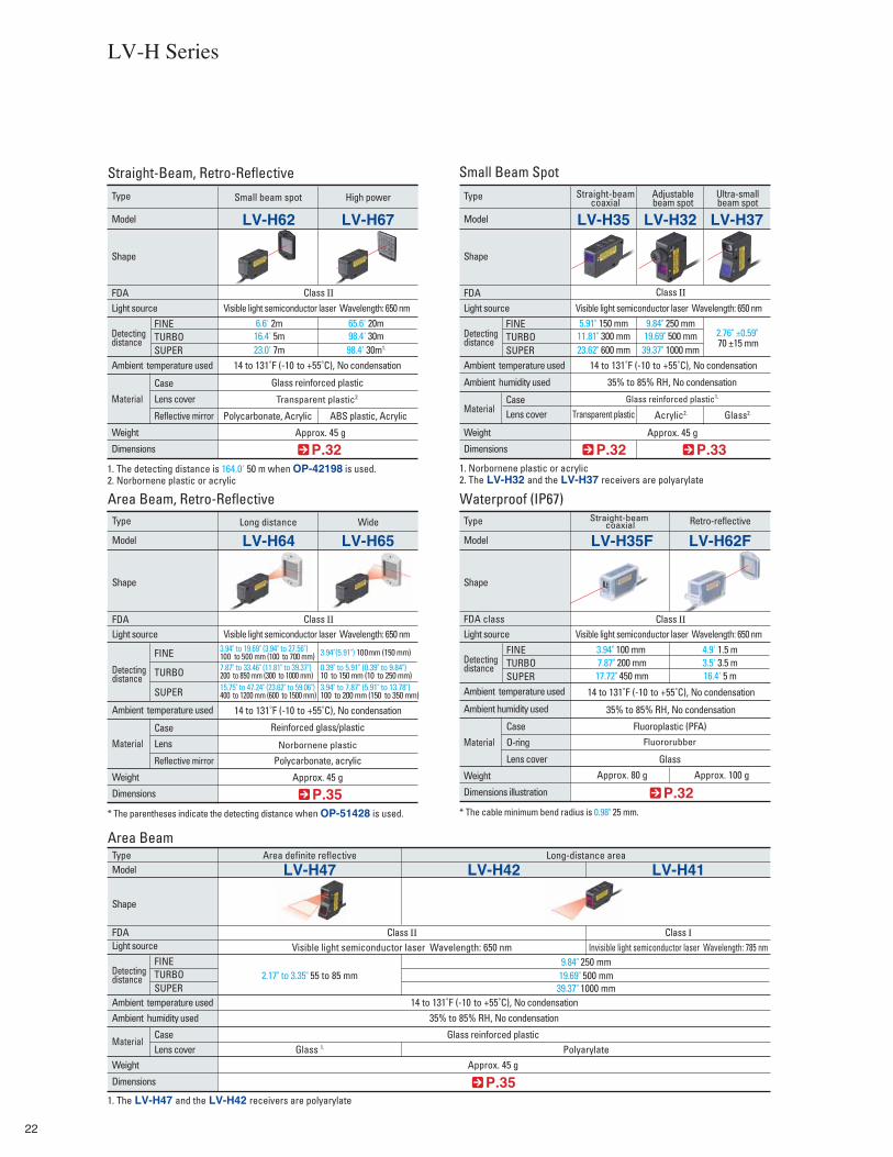
Straight-Beam, Retro-Reflective
P.32 P.33
P.35
FDA
CaseLens coverMaterial
35% to 85% RH, No condensation
Transparent plastic Acrylic2. Glass2.
Approx. 45 g
LV-H32
Visible light semiconductor laser Wavelength: 650 nm
LV-H37
2.76" ±0.59" 70 ±15 mm
LV-H35
Glass reinforced plastic1.
5.91" 150 mm11.81" 300 mm23.62" 600 mm
9.84" 250 mm19.69" 500 mm39.37" 1000 mm
Small Beam Spot
1. Norbornene plastic or acrylic2. The LV-H32 and the LV-H37 receivers are polyarylate
Area definite reflective Long-distance area
LV-H42 LV-H41
Visible light semiconductor laser Wavelength: 650 nm Invisible light semiconductor laser Wavelength: 785 nm
LV-H47
9.84" 250 mm19.69" 500 mm2.17" to 3.35" 55 to 85 mm
Glass 1. Polyarylate
39.37" 1000 mm
Area Beam
1. The LV-H47 and the LV-H42 receivers are polyarylate
Approx. 45 g
Class Ⅱ
Type Straight-beamcoaxial
Adjustablebeam spot
Ultra-smallbeam spot
Model
Shape
Weight
Dimensions
Ambient temperature used
Ambient humidity used
Light source
Detectingdistance TURBO
FINE
SUPER 14 to 131˚F (-10 to +55˚C), No condensation
P.32
FDA
Case
Lens cover
Reflective mirror
Material Transparent plastic2.
Glass reinforced plastic
14 to 131˚F (-10 to +55˚C), No condensation
Polycarbonate, Acrylic ABS plastic, Acrylic
Approx. 45 g
LV-H67
Visible light semiconductor laser Wavelength: 650 nm
LV-H62
6.6' 2m16.4' 5m23.0' 7m
65.6' 20m98.4' 30m98.4' 30m1.
1. The detecting distance is 164.0' 50 m when OP-42198 is used.2. Norbornene plastic or acrylic
Class Ⅱ
Type Small beam spot High power
Model
Shape
Weight
Dimensions
Ambient temperature used
Light source
Detectingdistance TURBO
FINE
SUPER
Area Beam, Retro-Reflective
P.35
FDA
Case
Lens
Reflective mirror
Material Norbornene plastic
Reinforced glass/plastic
Glass reinforced plastic
Polycarbonate, acrylic
Approx. 45 g
LV-H65
Visible light semiconductor laser Wavelength: 650 nm
LV-H64
3.94" to 19.69" (3.94" to 27.56") 100 to 500 mm (100 to 700 mm) 3.94"(5.91") 100mm (150 mm)
7.87" to 33.46" (11.81" to 39.37") 200 to 850 mm (300 to 1000 mm)
0.39" to 5.91" (0.39" to 9.84") 10 to 150 mm (10 to 250 mm)
15.75" to 47.24" (23.62" to 59.06") 400 to 1200 mm (600 to 1500 mm)
3.94" to 7.87" (5.91" to 13.78") 100 to 200 mm (150 to 350 mm)
* The parentheses indicate the detecting distance when OP-51428 is used.
Class Ⅱ
Type Long distance Wide
Model
Shape
Weight
Dimensions
Ambient temperature used
Light source
Detectingdistance TURBO
FINE
SUPER
FDA
CaseLens cover
Material
TypeModel
Shape
Weight
Dimensions
Ambient temperature usedAmbient humidity used
Light source
Detectingdistance TURBO
FINE
SUPER
14 to 131˚F (-10 to +55˚C), No condensation
14 to 131˚F (-10 to +55˚C), No condensation
Waterproof (IP67)
P.32
FDA class
Case
O-ring
Lens cover
Material Fluororubber
Fluoroplastic (PFA)
GlassApprox. 80 g Approx. 100 g
LV-H62F
Visible light semiconductor laser Wavelength: 650 nm
LV-H35F
3.94" 100 mm 7.87" 200 mm17.72" 450 mm
4.9' 1.5 m3.5' 3.5 m16.4' 5 m
* The cable minimum bend radius is 0.98" 25 mm.
Class Ⅱ
Type Straight-beam coaxial Retro-reflective
Model
Shape
Weight
Dimensions illustration
Ambient temperature used
Ambient humidity used
Light source
Detectingdistance TURBO
FINE
SUPER 14 to 131˚F (-10 to +55˚C), No condensation
35% to 85% RH, No condensation
35% to 85% RH, No condensation
Class Ⅱ Class Ⅰ
LV-H Series
23
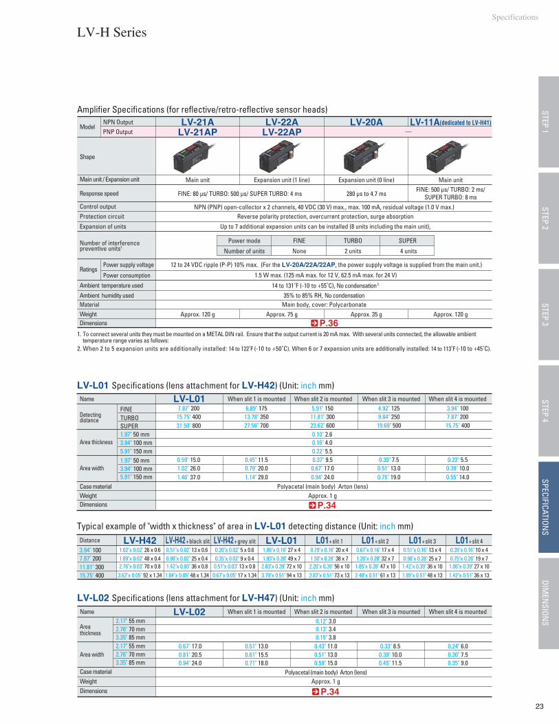
35% to 85% RH, No condensationMain body, cover: Polycarbonate
LV-21A LV-22A
Expansion unit (1 line)
12 to 24 VDC ripple (P-P) 10% max. (For the LV-20A/22A/22AP, the power supply voltage is supplied from the main unit.)
1.5 W max. (125 mA max. for 12 V, 62.5 mA max. for 24 V)
Approx. 120 g Approx. 75 g
LV-20A
Approx. 35 g
Ratings
FINE: 80 µs/ TURBO: 500 µs/ SUPER TURBO: 4 ms 280 µs to 4.7 msFINE: 500 µs/ TURBO: 2 ms/
SUPER TURBO: 8 msNPN (PNP) open-collector x 2 channels, 40 VDC (30 V) max., max. 100 mA, residual voltage (1.0 V max.)
Reverse polarity protection, overcurrent protection, surge absorption
Up to 7 additional expansion units can be installed (8 units including the main unit),
1. To connect several units they must be mounted on a METAL DIN rail. Ensure that the output current is 20 mA max. With several units connected, the allowable ambient temperature range varies as follows:
2. When 2 to 5 expansion units are additionally installed: 14 to 122˚F (-10 to +50˚C). When 6 or 7 expansion units are additionally installed: 14 to 113˚F (-10 to +45˚C).
FINE TURBOPower mode
Number of units None 2 units 4 units
SUPER
P.36
P.34
3.94" 1007.87" 20011.81" 30015.75" 400
LV-H42+ black slit0.51"x 0.02" 13 x 0.60.98"x 0.02" 25 x 0.41.42"x 0.03" 36 x 0.81.84"x 0.05" 48 x 1.34
LV-H42+ grey slit0.20"x 0.02" 5 x 0.60.35"x 0.02" 9 x 0.40.51"x 0.03" 13 x 0.80.67"x 0.05" 17 x 1.34
LV-L011.06"x 0.16" 27 x 41.93"x 0.28" 49 x 72.83"x 0.39" 72 x 103.70"x 0.51" 94 x 13
L01+ slit 10.79"x 0.16" 20 x 41.50"x 0.28" 38 x 72.20"x 0.39" 56 x 102.87"x 0.51" 73 x 13
L01+ slit 20.67"x 0.16" 17 x 41.26"x 0.28" 32 x 71.85"x 0.39" 47 x 102.40"x 0.51" 61 x 13
L01+ slit 30.51"x 0.16" 13 x 40.98"x 0.28" 25 x 71.42"x 0.39" 36 x 101.89"x 0.51" 48 x 13
L01+ slit 40.39"x 0.16" 10 x 40.75"x 0.28" 19 x 71.06"x 0.39" 27 x 101.42"x 0.51" 36 x 13
LV-H421.02"x 0.02" 26 x 0.61.89"x 0.02" 48 x 0.42.76"x 0.03" 70 x 0.83.62"x 0.05" 92 x 1.34
FINETURBOSUPER1.97" 50 mm3.94" 100 mm5.91" 150 mm1.97" 50 mm3.94" 100 mm5.91" 150 mm
LV-L017.87" 200
15.75" 40031.50" 800
0.59" 15.01.02" 26.01.46" 37.0
When slit 1 is mounted When slit 2 is mounted When slit 3 is mounted When slit 4 is mounted6.89" 17513.78" 35027.56" 700
0.45" 11.50.79" 20.01.14" 29.0
5.91" 15011.81" 30023.62" 6000.10" 2.60.16" 4.00.22" 5.50.37" 9.50.67" 17.00.94" 24.0
Approx. 1 g
4.92" 1259.84" 25019.69" 500
0.30" 7.50.51" 13.00.75" 19.0
3.94" 1007.87" 20015.75" 400
0.22" 5.50.39" 10.00.55" 14.0
LV-L01 Specifications (lens attachment for LV-H42) (Unit: inch mm)
Typical example of "width x thickness" of area in LV-L01 detecting distance (Unit: inch mm)
LV-L02 Specifications (lens attachment for LV-H47) (Unit: inch mm)LV-L02
0.67" 17.00.81" 20.50.94" 24.0
0.51" 13.00.61" 15.50.71" 18.0
0.43" 11.00.51" 13.00.59" 15.0
0.33" 8.50.39" 10.00.45" 11.5
0.24" 6.00.30" 7.50.35" 9.0
0.12" 3.00.13" 3.40.15" 3.8
Approx. 1 g
14 to 131˚F (-10 to +55˚C), No condensation 2.
Model
Name
Shape
NPN Output
Main unit / Expansion unit Main unit Expansion unit (0 line)
LV-11A(dedicated to LV-H41)
Approx. 120 g
Main unit
Response speed
Control outputProtection circuit
Ambient temperature used
Ambient humidity usedMaterial
Distance
WeightDimensions
Power supply voltage
Power consumption
Expansion of units
Number of interference preventive units1.
WeightCase material Polyacetal (main body) Arton (lens)
Dimensions
WeightCase material Polyacetal (main body) Arton (lens)
Dimensions
Detectingdistance
Area thickness
Area width
Name
Areathickness
Area width
P.34
2.17" 55 mm2.76" 70 mm3.35" 85 mm2.17" 55 mm2.76" 70 mm3.35" 85 mm
When slit 1 is mounted When slit 2 is mounted When slit 3 is mounted When slit 4 is mounted
Amplifier Specifications (for reflective/retro-reflective sensor heads) STEP 1STEP 3
STEP 4SPECIFICATION
SDIM
ENSION
SSTEP 2
LV-H SeriesSpecifications
PNP Output LV-21AP LV-22AP —
24
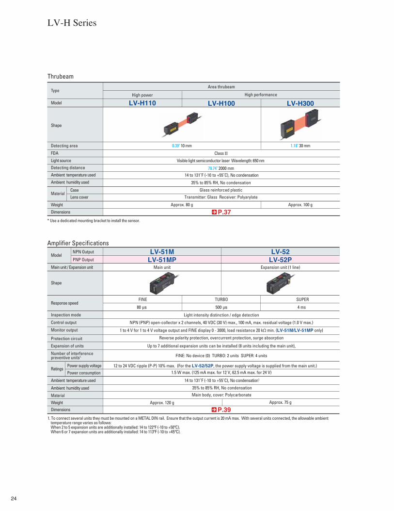
LV-H Series
ThrubeamArea thrubeam
0.39" 10 mm 1.18" 30 mm
78.74" 2000 mm
Visible light semiconductor laser Wavelength: 650 nm
LV-H100LV-H110High power High performance
LV-H300
* Use a dedicated mounting bracket to install the sensor.
P.37
P.39
Amplifier SpecificationsLV-51M LV-52
Main unit Expansion unit (1 line)
12 to 24 VDC ripple (P-P) 10% max. (For the LV-52/52P, the power supply voltage is supplied from the main unit.)
Approx. 120 g Approx. 75 g
1. To connect several units they must be mounted on a METAL DIN rail. Ensure that the output current is 20 mA max. With several units connected, the allowable ambient temperature range varies as follows: When 2 to 5 expansion units are additionally installed: 14 to 122ºF (-10 to +50ºC). When 6 or 7 expansion units are additionally installed: 14 to 113ºF (-10 to +45ºC).
FDA
Case
Lens coverMaterial
Type
Model
Shape
Detecting area
Weight
Dimensions
Ambient temperature used
Ambient humidity used
Light source
Detecting distance
Class Ⅱ
14 to 131˚F (-10 to +55˚C), No condensation
14 to 131˚F (-10 to +55˚C), No condensation1.
35% to 85% RH, No condensation
35% to 85% RH, No condensation
Main body, cover: Polycarbonate
Glass reinforced plastic
Transmitter: Glass Receiver: Polyarylate
Approx. 80 g Approx. 100 g
Ratings
Model
Shape
NPN Output
Main unit / Expansion unit
Response speed
Inspection mode
Control output
Monitor output
Protection circuit
Ambient temperature used
Ambient humidity used
Material
Weight
Dimensions
Power supply voltage
Power consumption
Expansion of units
Number of interference preventive units1.
TURBO SUPERFINE
500 µs
Light intensity distinction / edge detection
NPN (PNP) open-collector x 2 channels, 40 VDC (30 V) max., 100 mA, max. residual voltage (1.0 V max.)
1 to 4 V for 1 to 4 V voltage output and FINE display 0 - 3000, load resistance 20 kΩ min. (LV-51M/LV-51MP only)
Reverse polarity protection, overcurrent protection, surge absorption
Up to 7 additional expansion units can be installed (8 units including the main unit),
FINE: No device (0) TURBO: 2 units SUPER: 4 units
1.5 W max. (125 mA max. for 12 V, 62.5 mA max. for 24 V)
80 µs 4 ms
PNP Output LV-51MP LV-52P
25
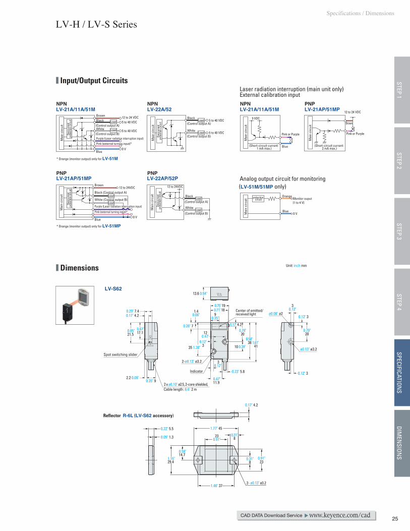
LV-H / LV-S Series
CAD DATA Download Service www.keyence.com/cad
Dimensions
STEP 1STEP 3
STEP 4SPECIFICATION
SDIM
ENSION
SSTEP 2
12 to 24VDC
Blue
Purple (Laser radiation interruption input)
White(Control output B)
(Control output A)BlackBrown
Mai
n ci
rcui
t
Over
curre
nt
prot
ectio
n circ
uitOv
ercu
rrent
pr
otec
tion c
ircuit
Mai
n ci
rcui
t
Over
curre
nt
prot
ectio
n circ
uit
12 to 24 VDC5 to 40 VDC
5 to 40 VDC
0 V
Pink (external turning input)*
Load
Load White
(Control output B)
(Control output A)
Black
5 to 40 VDC
5 to 40 VDCLoad
Load
Blue
Pink or Purple
5 VDC
Pink or Purple
Brown
(Short-circuit current: 2 mA max.)
(Short-circuit current: 1 mA max.)
12 to 24 VDC
White
(Control output B)
(Control output A)
BlackLoad
Load
Blue
Black (Control output A)
Brown12 to 24VDC
0 V
Load
Load
Blue
Orange
0 V
Monitor ouput(1 to 4 V)
protection circuit
Mai
n ci
rcui
t
Over
curre
nt
prot
ectio
n circ
uit
Mai
n ci
rcui
t
Pink (external turning input)*
Purple (Laser radiation interruption input)
White (Control output B)
Mai
n ci
rcui
t
Mai
n ci
rcui
tM
ain
circ
uit
Analog output circuit for monitoring
Laser radiation interruption (main unit only)External calibration input
* Orange (monitor output) only for LV-51M
* Orange (monitor output) only for LV-51MP
LV-21A/11A/51M LV-21AP/51MPLV-22A/52
LV-22AP/52PLV-21AP/51MP
LV-21A/11A/51M
(LV-51M/51MP only)
Input/Output Circuits
0.12" 3
0.12" 3
1.46" 37
0.17" 4.2
0.31"8
1.16"29.4
0.91"23
0.58"14.7
230.91"
0.31"8
1.77" 45
0.05" 1.3
0.22" 5.5
2- ø0.13" ø3.2
LV-S62
0.35" 9
0.17" 4.20.29" 7.4
0.67"17.10.85"
21.5
2.2 0.09"
Cable length: 6.6' 2 m
Spot switching slider
30.12"
0.79"20
2 x ø0.10" ø2.5, 2 -core shielded,
1.40.06"
0.28" 7
10 0.39"
0.79"20
0.71" 180.75" 19
0.47" 11.9
0.23" 5.8
0.17" 4.2
90.35"
13.6 0.54"
0.50" 38 1.61"
410.12"
3
120.47"
35 1.38"
30.12"
Center of emitted/ received light
Unit: inch mm
Indicator
2-ø0.13" ø3.2
ø0.08" ø2
ø0.13" ø3.2
Reflector R-6L (LV-S62 accessory)
Specifications / Dimensions
NPN
PNP PNP
NPN NPN PNP

26
LV-S Series
OP-84350L-shaped mounting bracket for LV-S62 (Option)
OP-84349Rear mounting bracket for the LV-S62 (Option)
Mounting bracket attached
Mounting bracket attached
(0.92")(23.3)
19.70.78"
15.50.61"
0.50" 12.818.8 0.74"
13.4 0.53"
(0.93")(23.5) (0.80")
(20.3) 0.77" 19.5
2.01" 51
130.51"
M3 screw
2.39" 60.7
1.57"40
0.94"24
0.35" 9
1.22"31
29.21.15"
1.03" 26.26 0.24"
0.14"3.5
10 0.39"
0.47"12
4.5 0.18"
0.63"16
0.83"21.2
4-M3
0.20"5
0.36"9.2
0.98" 251.34" 34
1.69"43
0.9 0.04" 0.75"19
0.98" 25
1.90"48.3
1.34" 34
14.5 0.57"
(2.07")(52.5)
0.04" 0.9 0.75" 19
Material: Stainless steelt=0.06" t=1.5Accessory screwM3, P=0.5× 7.3…1pieceMaterial: Stainless steel
0.20"5
6 0.24"
M3
1.46" 16
80.31"
40.16"
0.24" 6
0.20" 54 0.16"
0.43"11
3.40.13"
0.13" 3.4
2.07"52.5 1.95"
49.51.28"32.5 0.98"
258
0.31"
13.50.53"
0.79"20
Material Stainless steel t=0.06" 1.5
2- ø0.08" ø2
4-R0.07" R1.7
Material: Stainless steelt=0.06" t=1.5Accessory screws M3, P=0.5× 5…1pieceMaterial: Stainless steelM3, P=0.5× 16.5…1pieceMaterial: Stainless steelM3, P=0.5× 18…2pieceMaterial: Stainless steel
Accessory nutM3…1 pieceMaterial: Stainless steel
0.26" 6.7
Center of emitted/received light
Center of emitted/received light
Center of emitted/ received light
Center of emitted/ received light
Unit: inch mm
5 0.20"6.5 0.26"
8 0.31"12 0.47"15 0.59"
27
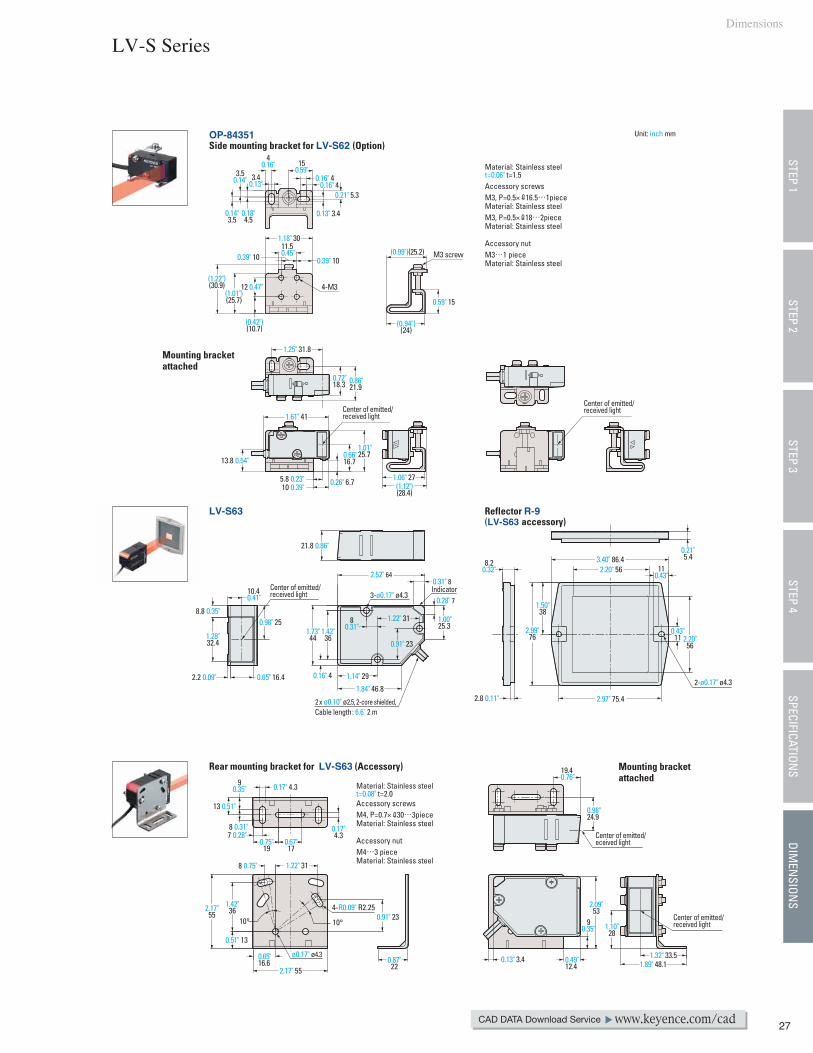
Dimensions
LV-S Series
CAD DATA Download Service www.keyence.com/cad
LV-S63 Reflector R-9(LV-S63 accessory)
Rear mounting bracket for LV-S63 (Accessory)
Mounting bracket attached
Mounting bracket attached
OP-84351Side mounting bracket for LV-S62 (Option)
Material: Stainless steelt=0.08" t=2.0Accessory screws M4, P=0.7× 30…3pieceMaterial: Stainless steel
Accessory nutM4…3 pieceMaterial: Stainless steel
(1.22")(30.9)
(1.01")(25.7)
0.39" 100.39" 1011.50.45"
12 0.47"
1.18" 30
(0.42")(10.7)
4-M3
3.50.14" 3.4
0.13"
0.14"3.5
0.18"4.5
0.21" 5.3
0.13" 3.4
40.16"
0.16" 40.16" 4
150.59"
(0.94")(24)
(0.99")(25.2)
0.59" 15
M3 screw
Material: Stainless steelt=0.06" t=1.5Accessory screws M3, P=0.5× 16.5…1pieceMaterial: Stainless steelM3, P=0.5× 18…2pieceMaterial: Stainless steel
Accessory nutM3…1 pieceMaterial: Stainless steel
0.87"22
1.32" 33.51.89" 48.10.13" 3.4 0.49"
12.4
19.40.76"
0.98"24.9
2.09"53
90.35" 1.10"
28
2.8 0.11"
8.20.32"
(1.12")(28.4)
2.99"76
3.40" 86.411
0.43"2.20" 56
2.97" 75.4
1.50"38
0.43"11 2.20"
56
0.21"5.4
1.28"32.4
0.65" 16.4
8.8 0.35"
2.2 0.09"
0.98" 25
10.40.41"
21.8 0.86"
5.8 0.23"10 0.39"
1.61" 41
1.06" 27
13.8 0.54"
1.01"25.70.66"
16.7
0.26" 6.7
0.72"18.3 0.86"
21.9
1.25" 31.8
8 0.31"7 0.28"
90.35"
13 0.51"
0.17" 4.3
0.17"4.3
0.67"17
0.65"16.6
0.75"19
2.17"55
2.17" 55
0.51" 13
1.42"36
8 0.75" 1.22" 31
0.91" 234-R0.09" R2.25
10° 10°
0.91" 23
Center of emitted/received light
Center of emitted/received light
Center of emitted/eceived light
Center of emitted/received light
Center of emitted/received light
1.42"36
80.31"1.73"
44
0.16" 4 1.14" 29
1.22" 31
2.52" 640.31" 8
0.28" 7
1.84" 46.8
1.00"25.3
2-ø0.17" ø4.3
3-ø0.17" ø4.3Indicator
STEP 1STEP 3
STEP 4SPECIFICATION
SDIM
ENSION
SSTEP 2
Cable length: 6.6' 2 m2 x ø0.10" ø2.5, 2 -core shielded,
Unit: inch mm
ø0.17" ø4.3
28
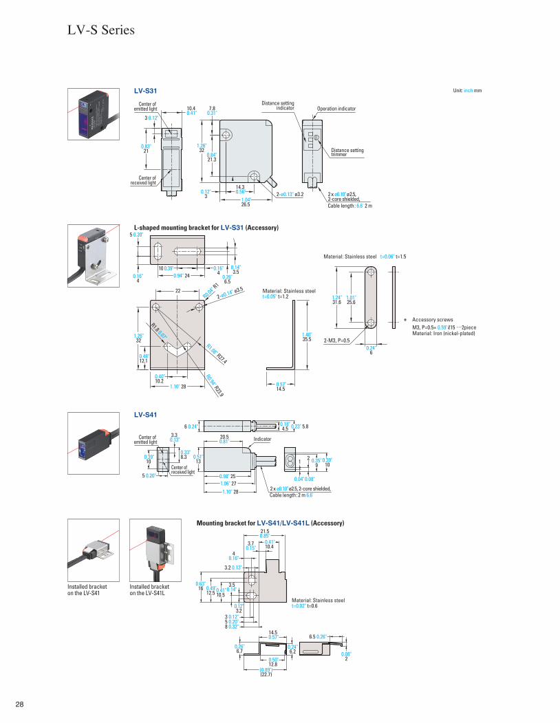
LV-S31
Mounting bracket for LV-S41/LV-S41L (Accessory)
LV-S41
L-shaped mounting bracket for LV-S31 (Accessory)
10.40.41"
1.26"32
1.04"26.5
6 0.24"
0.51"13
0.98" 25
Installed bracketon the LV-S41
Installed bracketon the LV-S41L
Center of emitted light
Center ofreceived light
Center of emitted light
Center ofreceived light
Distance settingindicator Operation indicator
Distance setting trimmer
3 0.12"
0.12"3
5 0.20"
0.16"4
0.16"4
10 0.39" 0.14"3.5
0.26"6.5
0.94" 24
22
1.40"35.5
1.24"31.6
1.01"25.6
0.24"6
2-M3, P=0.5
0.57"14.5
3.3 0.13" 20.5
0.81"
1.06" 271.10" 28
0.23" 5.8
0.39"10
0.35"9
1
21.50.85"
0.41"10.43.7
0.15"4
0.16"
3.2 0.13"
3 0.12"5 0.20"8 0.32"
0.63"16 0.49"
12.5 0.41"10.5
3.50.14"
0.12"3.2
0.26"6.7
(0.89")(22.7)
6.5 0.26"
0.08"2
0.24"6.2
0.50"12.8
14.50.57"
2
0.18"4.5
0.39"10
5 0.20"
0.33"8.3
1.26"32
0.48"12.1
0.40"10.2
1.10" 28
R0.04"
R1
R1.08" R27.4
R1.8 0.07"
R0.94" R23.9
2-ø0.13" ø3.214.30.56"
0.83"21
7.80.31"
0.84"21.3
Cable length: 6.6' 2 m
Material: Stainless steelt=0.05" t=1.2
Material: Stainless steel t=0.06" t=1.5
2-ø0.14" ø3.5
* Accessory screws M3, P=0.5× 0.59" 15 …2pieceMaterial: Iron (nickel-plated)
Indicator
Cable length:2 m 6.6'
Material: Stainless steel t=0.02" t=0.6
2 x ø0.10" ø 2.5, 2 -core shielded,
2 x ø0.10" ø2.5, 2 -core shielded,
LV-S Series
0.04"0.08"
Unit: inch mm
29
0.76" 19.2
0.72" 18.3
0.76"19.2
0.72"18.3
1.46" 37
0.91" 23
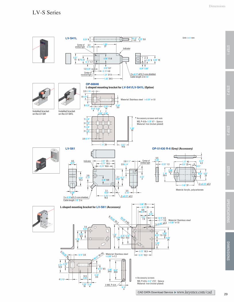
OP-66846L-shaped mounting bracket for LV-S41/LV-S41L (Option)
LV-S41L 0.24" 6
0.51"13
1.24" 31.5
LV-S61 OP-51430 R-6 (Grey) (Accessory)
L-shaped mounting bracket for LV-S61 (Accessory)
0.91" 238.50.33"
0.71"18
1.16"29.4
1.77" 45
Material: Acrylic, polycarbonate
Installed bracketon the LV-S41
Installed bracketon the LV-S41L
1.06"273.7
0.15"
0.18"4.5 0.23" 5.8
1
0.04" 0.08"
20.35" 9 0.39" 109.7 0.38"
0.19" 4.7
1.3 0.05"0.19" 4.8
0.46" 11.6
0.03" 0.7
1.36" 34.5
3.5 0.14"
0.14"3.5
8 0.31"
5 0.20"0.16"
40.28"
7 70.28"
70.28"
0.55"14
7 0.28"
7 0.28"
3 0.12"
3 0.12"
3.5 0.14"
1.14" 29
0.60"15.3
2.8 0.11"
0.12"3
3.50.14"
3.5 0.14"
2.10.08"
2.10.08"
0.76"19.3
0.79"20
0.14" 3.5
0.57"14.5
0.20"5
4 0.16"
0.39"10
12.50.49"
0.16"4
0.14"3.5
0.98"24.8
2-M2, P=0.4
0.82"20.8
0.16"4
0.33" 8.5
0.39"9.9
7.90.31"
1.06"27 0.94"
240.94"
24
0.18" 4.50.11" 2.9
80.31"
0.98" 250.79" 209.9
0.39"
0.31"7.9
0.39"9.90.31" 7.9
0.44"11.1
5.50.22"
0.55" 1.3
0.58"14.7
8 0.31"
0.17"4.2
0.91"23
0.31"83.9
0.15"
0.20"5
0.77" 19.50.74" 18.8
0.35" 8.9
0.57"14.5
1.26"32
* Accessory screws M2, P=0.4× 0.47" 12…2pieceMaterial: Iron (nickel-plated)
* Accessory screws and nuts M3, P=0.5× 0.28" 7…2pieceMaterial: Iron (nickel-plated)
Center of emitted light
Center ofreceived light
Cable length:2 m 6.6'
Indicator
Material: Stainless steel t=0.04" t=1.0
Material: Stainless steelt=0.04" t=1.0
Material: Stainless steelt=0.05" t=1.2
Center of emitted light
Cable length: 6.6' 2 m
Indicator
2-ø0.09" ø2.2
2-ø0.13" ø3.2
R0.08" 4-R2
2-R0.08" R2(4-R0.07" R1.75)
6-R0.05" R1.23-ø0.09" ø2.3
2 x ø0.10" ø2.5, 2 -core shielded,
2 x ø0.10"ø2.5, 2 -core shielded,
Dimensions
LV-S Series
CAD DATA Download Service www.keyence.com/cad
STEP 1STEP 3
STEP 4SPECIFICATION
SDIM
ENSION
SSTEP 2
Unit: inch mm
30
M6, P=0.75Stainless steel
M6, P=0.75Stainless steel
M6, P=0.75Stainless steel
7 0.28"
120.47"
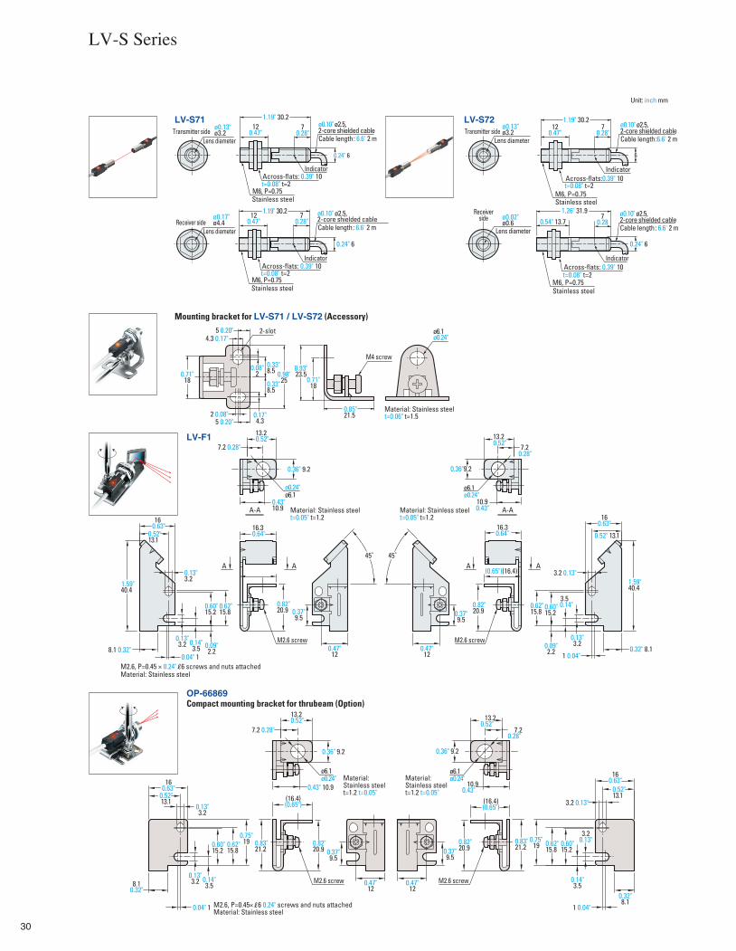
Mounting bracket for LV-S71 / LV-S72 (Accessory)
LV-S72LV-S71
1.26" 31.9
0.24" 6
M6, P=0.75
1.19" 30.2 1.19" 30.2
1.19" 30.2
LV-F1
OP-66869Compact mounting bracket for thrubeam (Option)
ø0.13"ø3.2
ø0.13"ø3.2
ø0.17"ø4.4
ø0.02"ø0.6
ø6.1ø0.24"
ø0.24"ø6.1
ø6.1ø0.24"
ø6.1ø0.24"
ø6.1ø0.24"
Lens diameter
Lens diameter
Transmitter side
Receiver sideLens diameter
Receiverside
120.47"
120.47"
7 0.28"
7 0.28"
5 0.20"4.3 0.17"
0.08"2
0.33"8.5
0.33"8.5
0.17"4.3
13.20.52"
13.20.52" 13.2
0.52"
13.20.52" 7.2 0.28"
7.2 0.28" 7.20.28"
7.20.28"
160.63"
160.63"
160.63"
16.30.64"
160.63"16.3
0.64"
0.62"15.8
0.62"15.8
0.62"15.8
0.62"15.8
(16.4)(0.65") (16.4)
(0.65")
(0.65")(16.4)
0.82"20.9
0.82"20.9
0.82"20.9
0.82"20.9
M2.6 screw
M2.6 screw M2.6 screw
M2.6 screw
0.37"9.5
0.37"9.5
0.37"9.5
0.37"9.5
0.47"12
0.47"12
0.47"12
0.47"12
45˚ 45˚
0.52"13.1
0.52"13.1
0.52"13.1
0.52" 13.1
0.13"3.2
0.13"3.2
3.2 0.13"
3.2 0.13"
0.13"3.2
0.13"3.2
3.20.13"
0.13"3.2
0.60"15.2
0.60"15.2
0.60"15.2
0.60"15.2
8.1 0.32"
8.10.32"
0.32"8.1
0.32" 8.10.04" 1
0.04" 1 1 0.04"
1 0.04"
A A A A
0.09"2.2
0.09"2.2
0.14"3.5
0.14"3.5
0.14"3.5
3.50.14"
1.59"40.4
1.59"40.4
0.36" 9.2
0.36" 9.2
0.43"10.9
0.43" 10.9 10.9 0.43"
10.9 0.43"A-A A-A
0.36"9.2
2 0.08"5 0.20"
0.98"25
0.93"23.5
0.71"18
0.85"21.5
M4 screw
0.71"18
2-slot
Across-flats: 0.39" 10t=0.08" t=2
Across-flats:0.39" 10t=0.08" t=2
Across-flats: 0.39" 10t=0.08" t=2
Across-flats: 0.39" 10t=0.08" t=2
Cable length: 6.6' 2 m
ø0.10" ø2.5, 2 -core shielded cable
Cable length:6.6' 2 m
ø0.10" ø2.5, 2 -core shielded cable
Cable length: 6.6' 2 m
ø0.10" ø2.5, 2 -core shielded cable
Cable length: 6.6' 2 m
ø0.10" ø2.5,2 -core shielded cable
Indicator
Indicator
Stainless steel
Lens diameterTransmitter side
0.24" 6
0.24" 6
6
0.54" 13.77
0.28
Indicator
Indicator
Material: Stainless steel t=0.06" t=1.5
Material: Stainless steelt=0.05" t=1.2
Material: Stainless steelt=0.05" t=1.2
0.75"19 0.75"
190.83"21.2
0.83"21.2
0.36" 9.2
Material: Stainless steelt=1.2 t=0.05"
Material: Stainless steelt=1.2 t=0.05"
M2.6, P=0.45 × 0.24" 6 screws and nuts attachedMaterial: Stainless steel
M2.6, P=0.45× 6 0.24" screws and nuts attachedMaterial: Stainless steel
LV-S Series
Unit: inch mm
31
Dimensions
0.59"15
0.35"9
1.24"31.5
3.09"78.6
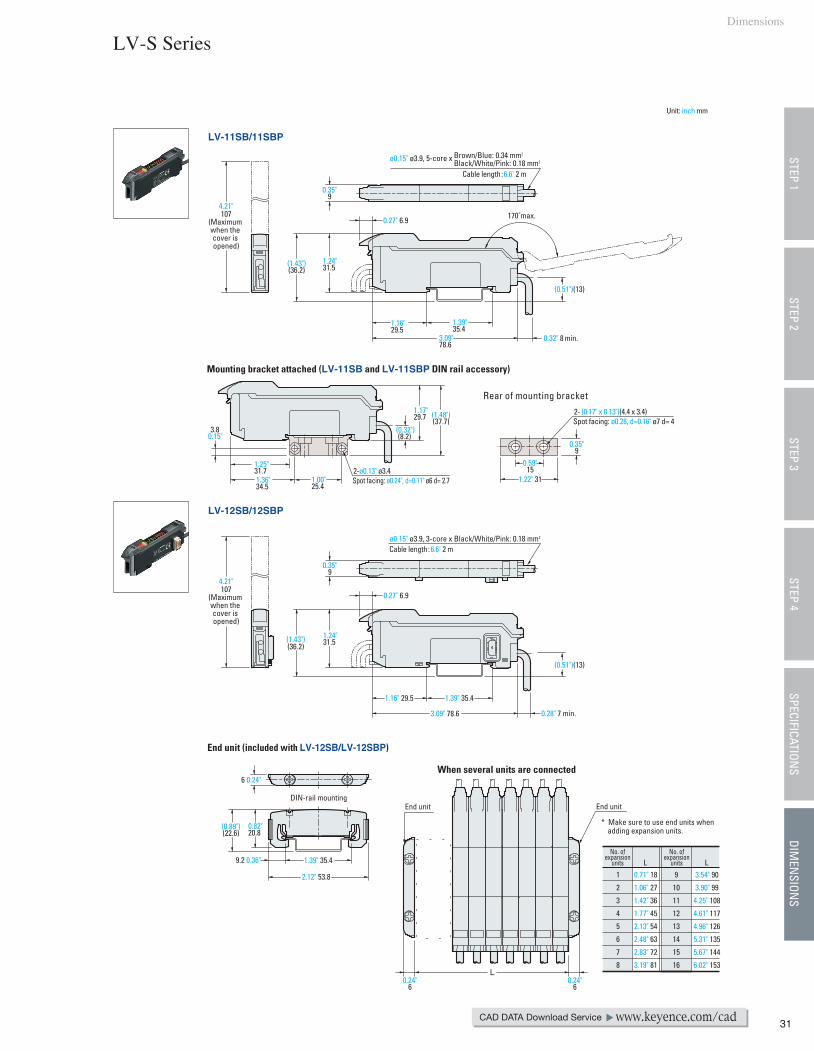
LV-11SB/11SBP
LV-12SB/12SBP
Mounting bracket attached (LV-11SB and LV-11SBP DIN rail accessory)
End unit (included with LV-12SB/LV-12SBP)
When several units are connected
0.27" 6.9
0.27" 6.9
(1.43")(36.2)
(1.43")(36.2)
(0.51")(13)
(0.51")(13)
0.32" 8 min.
Rear of mounting bracket
ø0.15" ø3.9, 5-core x Brown/Blue: 0.34 mm2
Black/White/Pink: 0.18 mm2
170˚ max.
1.16"29.5
1.39"35.4
1.16" 29.5 1.39" 35.4
1.39" 35.4
0.35"9
(1.48")(37.7)
1.17"29.7
(0.32")(8.2)
1.00"25.4
0.35"9
1.24"31.5
3.09" 78.6
6 0.24"
(0.89")(22.6)
0.82"20.8
9.2 0.36"
2.12" 53.8
DIN-rail mounting
1.36"34.5
1.25"31.7
3.80.15"
1.22" 31
Cable length:6.6' 2 m
ø0.15" ø3.9, 3-core x Black/White/Pink: 0.18 mm2
Cable length:6.6' 2 m
2- (0.17" x 0.13")(4.4 x 3.4)Spot facing: ø0.28, d=0.16" ø7 d= 4
2-ø0.13" ø3.4Spot facing: ø0.24", d=0.11" ø6 d= 2.7
0.28" 7 min.
End unit
LNo. of
expansionunits
No. ofexpansion
units
1
2
3
4
5
6
7
8
9
10
11
12
13
14
15
16
0.71" 18
1.06" 27
1.42" 36
1.77" 45
2.13" 54
2.48" 63
2.83" 72
3.19" 81
L3.54" 90
3.90" 99
4.25" 108
4.61" 117
4.96" 126
5.31" 135
5.67" 144
6.02" 153
* Make sure to use end units when adding expansion units.
End unit
LV-S Series
CAD DATA Download Service www.keyence.com/cad
STEP 1STEP 3
STEP 4SPECIFICATION
SDIM
ENSION
SSTEP 2
0.24"6
0.24"6
Unit: inch mm
4.21"107
(Maximum when the cover is opened)
4.21"107
(Maximum when the cover is opened)
32
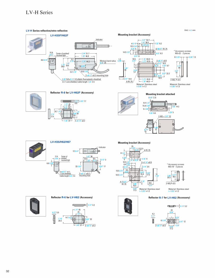
LV-H Series reflective/retro-reflective
* Accessory screws M3×22…2 pieces
Mounting bracket (Accessory)LV-H35F/H62F
1.05"26.6
2.04" 51.7
7.8 0.31"
1.85" 46.9
1.13"28.6
1.74" 44.33.2
3.2 0.13"
8.6 0.34"
15.8 0.62"
10.9 0.43"
0.57" 14.56-R1.75
1.81"46
1.20.05"
6 0.24"
1.77"45
0.06" 1.5
2.01"51
0.20" 5
0.31" 8
14.5 0.57"
4 0.16"15.5 0.61"
10 0.39"7
1.44" 36.5 0.32" 8.2
0.87" 22.2
0.34" 8.7
1.72" 43.8
1.72" 43.8
1.76" 44.8
1.76" 44.8
10.52-M3, P=0.5
5.1
5.1 0.41" 10.5
0.26"5.1
10.50.41"
2.07" 52.7
8-R0.07" R1.75
0.25" 6.3
Mounting bracket (Accessory)
14.5
31
4 0.16"8.4 0.33"
0.14" 3.5
10.5 0.41"
8.410.5 0.41"
10.5 0.41"0.65"16.4 0.69"
17.5
40.65"16.40.69"17.5
0.16" 40.16" 40.20"
5
8 0.31"
0.39" 10
12.525
0.77"19.51.00"
25.5
4-R0.07"
4-R1.75
2-M3,P=0.5
* Accessory screws M3×18…2 pieces
Material: Stainless steelt= 0.05" t=1.2
Material: Stainless steelt= 0.05" t=1.2
6.6 0.26"
12.40.49"
23 0.91"
0.12" 3
0.67" 17
23.5 9.51.42" 36
12 0.47"
LV-H35/H62/H67
1.77" 45
0.94" 24
1.46" 37
0.94"240.74"
37.4
6.80.30" 7.7
1.14" 29
1.14"29
18.7 1.47"
0.22" 5.5
0.17" 4.2
230.91"
1.77" 45
1.46" 37
0.91" 231.16"29.4
14.7 0.58"
Mounting bracket attached
2-M3 × 0.87" 22
1.46"370.75"
19
9.4 0.37"
0.26" 6.5
0.56" 14.2
(0.09" 2.2)
15.9 0.63"
0.20" 5
5 0.20"
Reflector R-7 for LV-H62 (Accessory)
4.20.17"
0.13" 3.2
240.94"
0.68"17.2
7
7 0.47" 126 0.24"
Reflector R-6 for LV-H62 (Accessory)
Indicator
Center of emitted/ received light
Center of emitted/ received light
0.20" 5.0 x 0.13" 3.2 elliptic fluoroplastic sheathed
2-ø0.13" ø3.2 mounting hole
Minimum bend radius0.98" 25
2 x 1 -core shielded, Cable length: 6.6' 2 m
2-ø0.13" ø3.2 mounting hole
2-ø0.13" ø3.2 2-ø0.13" ø3.2
Cable length:6.6' 2 m
2-ø0.14" ø3.5
2-ø0.13" ø3.2
Material: Stainless steelt=0.05" t=1.2
Material: Stainless steelt=0.06" t=1.5
Indicator
2 xø0.07" ø1.7, 1-core shielded,
2-ø0.14" ø3.5
Reflector R-8 for LV-H62F (Accessory)
LV-H Series
0.27"
0.93" 0.37"
0.98"0.49"
0.33"
0.16"R1.75
1.22"
0.57"
0.28"
0.28"
Unit: inch mm
0.13"
0.28"
0.41"0.20"
0.20"
33
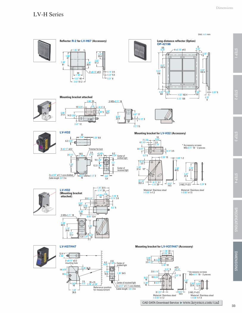
Reflector R-2 for LV-H67 (Accessory)
1.85" 47
1.85"47
1.01"25.6
2.02"51.21.20"
30.42.40"
61
301.18"
1.57" 402.02" 51.2
0.14" 3.50.22" 5.5
0.31" 8
Long-distance reflector (Option)OP-42198
5.91"150
4.03"102.4
4.03"102.4
8.80.35"
0.35"8.8
0.32"8
0.20" 54.03" 102.4
5.12" 130
0.35"8.8
0.35"8.8
80.32"
0.32"8
14.2 0.56"0.86"21.9
0.47" 12
0.98" 25
10 0.39" 0.16" 47
0.28"
0.62"15.70.20" 5
0.12" 30.94"23.9
0.3" 7.5
0.67" 17
2-M3×0.71" 18
Mounting bracket attached
18.50.73"3 0.12"
3.50.14"
1.06"27
0.63"16
0.12" 3
6.20.24"
1.3"3312.2 0.48"
10 0.39"
0.49"12.4
6.2 0.24"
220.87" 0.26" 6.6
LV-H32
0.24" 6
1.47"37.4
2-M3, P=0.5
1.24"31.4
R1.24"R31.4
1.24"31.4 10°
0.59" 15
0.14"3.5
0.15" 3.71.14" 29
140.55"7 0.28"
8 0.31"0.14" 3.5
3.50.14"
4 0.16"
0.2" 5
Mounting bracket for LV-H32 (Accessory)
1.59"40.5
0.05" 1.2
0.57"14.5
LV-H32(Mounting bracket attached)
1.59"40.5
2-M3×0.71" 18
1.18"29.9
0.7"17.7
1.06"27
0.39"106.9 0.27"
1.28" 32.51.14" 29
0.55"14
70.28"
0.16" 40.14" 3.5
0.2" 5
3.5 0.14"
0.56"14.2
0.81"20.7
0.38"9.6
0.49" 12.4
LV-H37/H47
0.73"18.5
6.20.24"
1.36" 34.5
(12)0.47"
0.24" (6.2)
70 ±152.76" ±0.59"
12.4
14 0.55"
8 0.31"
1.04"26.5
7.50.3"0.63"
16
Mounting bracket for LV-H37/H47 (Accessory)
0.57"14.5
1.57"40
0.31" 8
0.31" 8
8 0.31"
8 0.31"
3.5 0.14"
0.39"10
0.63"16
10 0.39"
3.5 0.14"0.39" 10
1.30" 330.94" 24
6 0.24"
0.94"23.9
2-M3, P=0.5
0.70"17.9
0.49"12.52-ø0.13" ø3.2
mounting hole
ø3.5ø0.14"
2-ø0.18" ø4.5
4-ø0.18" ø4.5
Material: Stainless steelt=0.05" t=1.2
Material: Stainless steelt=0.06" t=1.5
Material: Stainless steelt=0.05" t=1.2
Material: Stainless steelt=0.06" t=1.5
* Accessory screws M3×0.71" 18…2 pieces
Center of emitted light
Trimmer for lock
Center ofreceived light
Center of emitted light
Center of received light
2-ø0.13" ø3.2
ø0.45"ø11.4
Cable length: 6.6' 2 m2 x ø0.07" ø1.7, 1 -core shielded,
Cable length: 6.6' 2 m2 x ø0.07" ø1.7, 1 -core shielded,
Reference position for measurement
* Accessory screws M3×0.71" 18…2 pieces
Dimensions
LV-H Series
CAD DATA Download Service www.keyence.com/cad
STEP 1STEP 3
STEP 4SPECIFICATION
SDIM
ENSION
SSTEP 2
0.49"
Unit: inch mm
34
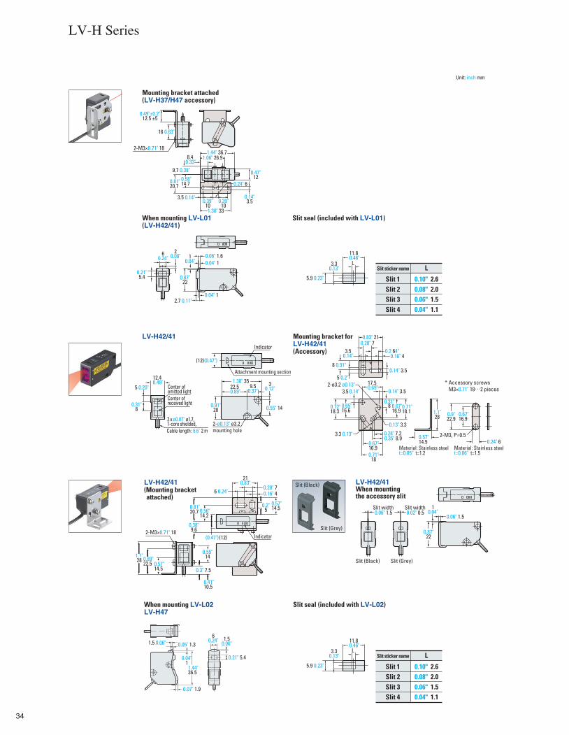
Mounting bracket attached(LV-H37/H47 accessory)
16 0.63"
0.49"±0.2"12.5 ±5
2-M3×0.71" 181.44" 36.7
0.14"3.5
1.30" 33
1.06" 26.98.4
9.7 0.38"
0.81"20.7
0.47"12
When mounting LV-L01(LV-H42/41)
Slit 1Slit 2Slit 3Slit 4
0.10"0.08"0.06"0.04"
2.62.01.51.1
Slit sticker name L0.87"
22
20.08" 0.06" 1.66
0.24"0.04" 1
0.04" 1
L
11.80.46"
3.30.13"
5.9 0.23"
10.04"
Slit seal (included with LV-L01)
Slit 1Slit 2Slit 3Slit 4
0.10"0.08"0.06"0.04"
2.62.01.51.1
Slit sticker name LL
11.80.46"
3.30.13"
5.9 0.23"
0.91"20 0.55" 14
1.38" 3522.50.89"
(12)(0.47")
9.50.37"
30.12"
LV-H42/41
12.40.49"
Attachment mounting section8 0.31"
0.14" 3.5
0.16" 4
0.9"22.9
0.67"16.9
2-M3, P=0.5
1.1"28
0.57"14.5
0.14" 3.53.5
0.13" 3.3
0.28" 7.20.35" 8.9
0.71"18.1
0.71"18
Mounting bracket for LV-H42/41 (Accessory)
1.1"28
2-M3×0.71" 18
0.89"22.5
0.55"14
0.3" 7.50.57"14.5
LV-H42/41(Mounting bracket attached)
0.56"14.2
0.28" 70.16" 4
0.2"5
0.57"14.5
Slit (Black)
Slit (Grey)0.38"9.6
(12)
LV-H42/41When mounting the accessory slit
0.87"22
10.04"0.06" 1.5
0.06" 1.5
Slit width0.02" 0.5
Slit width
Slit (Black) Slit (Grey)
When mounting LV-L02LV-H47
Slit seal (included with LV-L02)
1.44"36.5
0.05" 1.31.5 0.06"6
0.24"
0.07" 1.9
1.50.06"
0.21" 5.4
Indicator
Center ofreceived light
Center of emitted light
Cable length: 6.6' 2 m
2 x ø0.07" ø1.7, 1-core shielded, 2-ø0.13" ø3.2
mounting hole
* Accessory screws M3×0.71" 18…2 pieces
Material: Stainless steelt=0.05" t=1.2
Material: Stainless steelt=0.06" t=1.5
2-ø3.2 ø0.13"
Indicator
LV-H Series
0.33"
0.58"14.7
3.5 0.14"0.39"
100.39"
10
0.24" 6
0.21"5.4
2.7 0.11"
0.04"1
0.31"8
5 0.20"
0.24" 6
3.50.14"
0.28" 70.2 64"
5 0.2"
0.83" 21
17.50.69"
0.14"
0.31"8 0.67"
16.9
3.3 0.13"
0.67"16.9
0.65"16.6
0.72"18.3
(0.47")
0.81"20.7
6 0.24"
210.83"
0.41"10.5
Unit: inch mm
35
(0.47")(12)
1.69" 42.8
30.12"
0.67" 17
12.40.49"
6.1 0.24"
25
33.746.2
15.2
(0.47")(12)
23
9.5
3
17
12.4
6.66.1
25
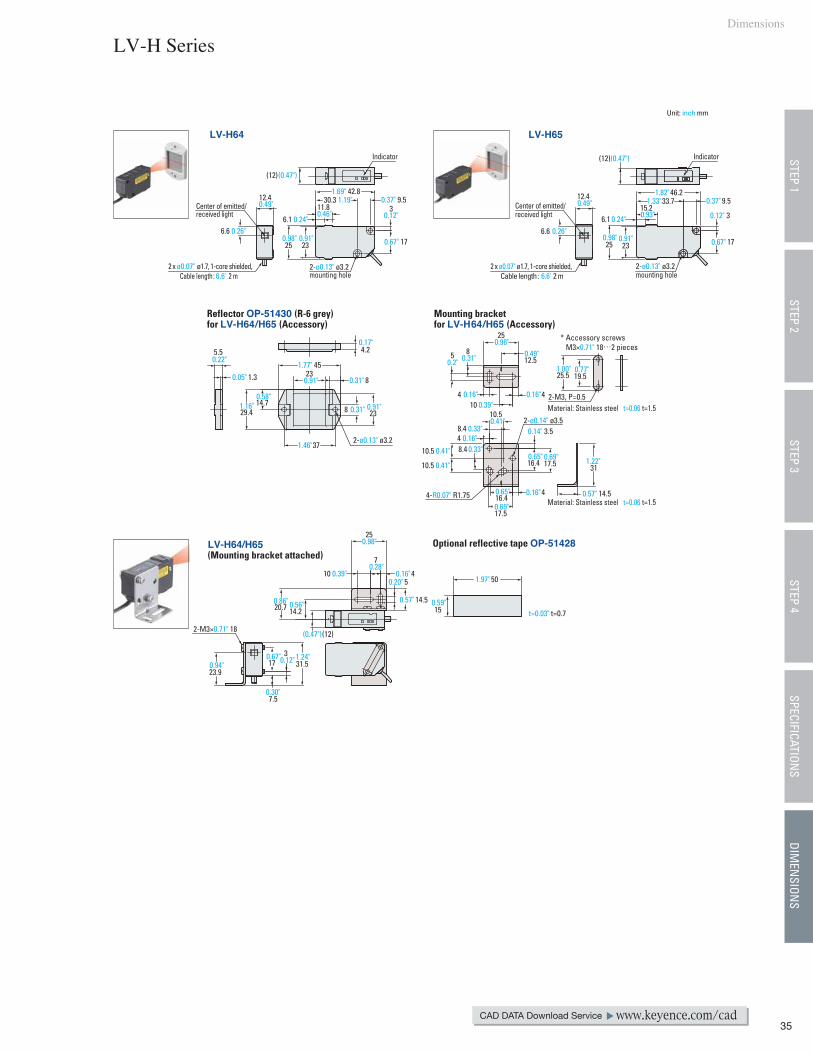
LV-H64 LV-H65
4.2
829.4 2314.7
238
45
37
1.3
5.5
Reflector OP-51430 (R-6 grey) for LV-H64/H65 (Accessory)
19.525.5
2-M3, P=0.5
14.5
31
0.14" 3.5
16.4 17.5
10.5
10.5
8.448.4
10.5
16.44
17.5
4-R0.07" R1.75
410
12.5
25
85
Mounting bracket for LV-H64/H65 (Accessory)
5
14.5
10
7
4
25
(12)(0.47")
14.220.7
317
7.5
23.9
2-M3×0.71" 18
31.5
50
t=0.03" t=0.715
LV-H64/H65 (Mounting bracket attached)
Optional reflective tape OP-51428
Center of emitted/received light
Center of emitted/received light
Indicator Indicator
Cable length: 6.6' 2 m2 x ø0.07" ø1.7, 1 -core shielded,
Cable length: 6.6' 2 m2 x ø0.07" ø1.7, 1 -core shielded,2-ø0.13" ø3.2
mounting hole2-ø0.13" ø3.2 mounting hole
* Accessory screws M3×0.71" 18…2 pieces
Material: Stainless steel t=0.06 t=1.5
Material: Stainless steel t=0.06 t=1.5
2-ø0.14" ø3.5
2-ø0.13" ø3.2
Dimensions
LV-H Series
STEP 1STEP 3
STEP 4SPECIFICATION
SDIM
ENSION
SSTEP 2
CAD DATA Download Service www.keyence.com/cad
6.6 0.26"
30.3 1.19"11.80.46"
0.37" 9.5
0.98"23
0.91"0.26"
0.49"1.82"
1.33"
0.93"
0.37"
0.24" 0.12"
0.67"0.98" 0.91"
0.22"
0.05"
0.17"
1.77"
0.31"
0.91"0.31"
1.46"
0.91"
0.58"1.16"
0.98"
0.31"0.2"
0.39"0.16" 40.16"
0.49"
0.41"
0.41" 0.33"
0.41"
0.33"
0.69"
0.69"
0.65"
0.65"
0.16"
0.16"
1.22"
0.57"
1.00" 0.77"
0.86" 0.56"
0.39"0.28"
0.16"0.20"
0.57" 0.59"
1.97"
0.98"
0.94"
0.30"
0.67"0.12" 1.24"
Unit: inch mm
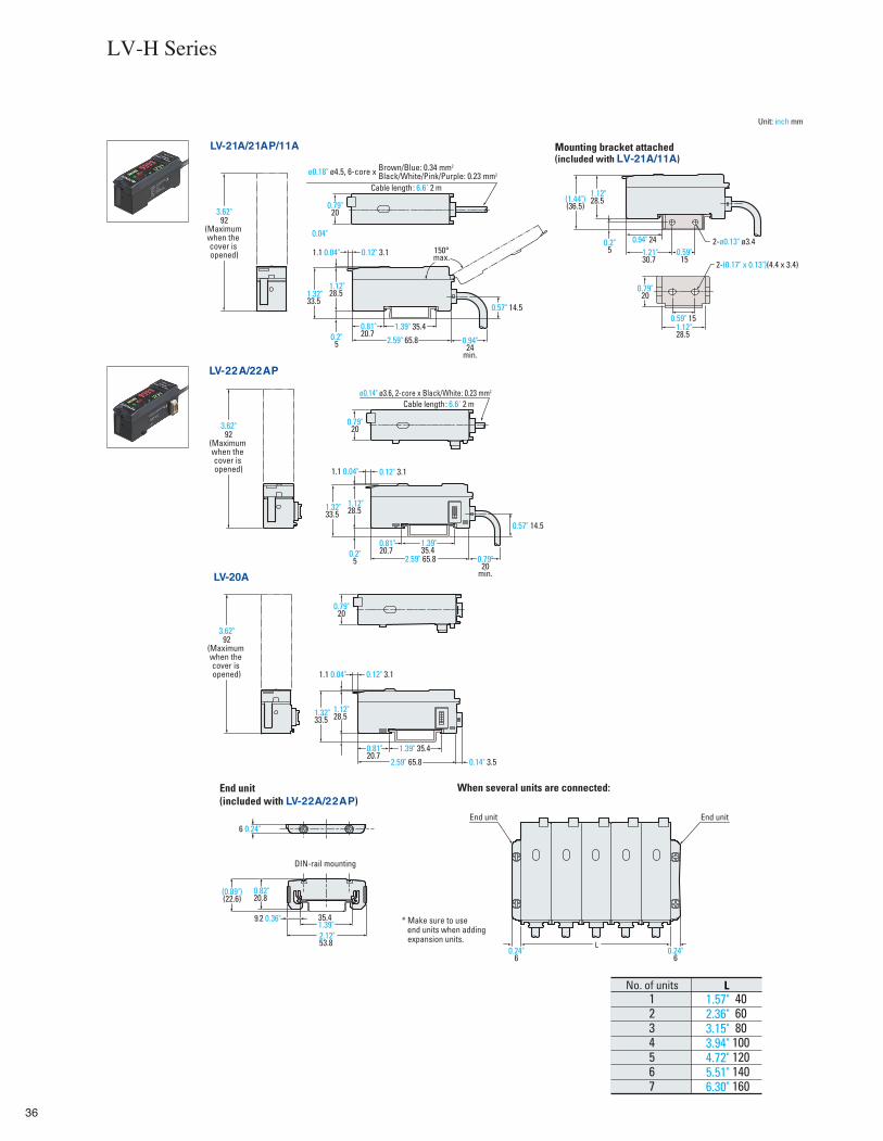
36
End unit End unit
L
1.1 0.04"
1.12"28.51.32"
33.5
0.81"20.7
1.39" 35.4
2.59" 65.8 0.14" 3.5
0.12" 3.1
0.79"20
LV-20A
1.1 0.04"
1.12"28.5
0.2"5
1.32"33.5
1.39"35.4
0.57" 14.5
0.79"20
min.
2.59" 65.8
0.12" 3.1
0.79"20
LV-22A/22AP
End unit (included with LV-22A/22AP)
When several units are connected:
1.12"28.5(1.44")
(36.5)
0.2"5
0.94" 241.21"30.7
0.59"15
2-(0.17" x 0.13")(4.4 x 3.4)
0.59" 15
0.79"20
1.12"28.5
Mounting bracket attached(included with LV-21A/11A)
1.12"28.51.32"
33.5
0.81"20.7
1.39" 35.4
0.57" 14.5
0.94"24
min.
2.59" 65.8
0.12" 3.11.1 0.04" 150°max.
3.62"92
(Maximum when the cover is opened)
0.79"20
LV-21A/21AP/11A
0.82"20.8
35.41.39"2.12"53.8
9.2 0.36"
(0.89")(22.6)
DIN-rail mounting
LNo. of units
* Make sure to use end units when adding expansion units.
ø0.18" ø4.5, 6-core x Brown/Blue: 0.34 mm2
Black/White/Pink/Purple: 0.23 mm2
ø0.14" ø3.6, 2-core x Black/White: 0.23 mm2 Cable length: 6.6' 2 m
2-ø0.13" ø3.4
1234567
406080100120140160
Cable length: 6.6' 2 m
LV-H Series
0.04"
0.2"5
3.62"92
(Maximum when the cover is opened)
3.62"92
(Maximum when the cover is opened)
0.81"20.7
6 0.24"
1.57"2.36"3.15"3.94"4.72"5.51"6.30"
Unit: inch mm
0.24"6
0.24"6
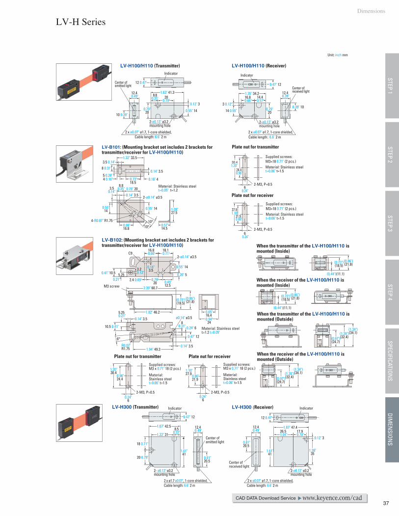
37
LV-H100/H110 (Receiver)LV-H100/H110 (Transmitter)
8.80.35"
1.63" 41.3 1.35" 34.2
0.79"2010 0.39"
200.79"
0.12" 3
0.55" 14 0.79"20
0.47" 12
12.40.39"
0.39" 1014 0.55"
3 0.12"
16.80.66"
14.40.57"
2-M3, P=0.5
Plate nut for transmitter
Plate nut for receiver
Material: Stainless steel t=0.05" t=1.2
4-R0.07" R1.75
LV-B101: (Mounting bracket set includes 2 brackets for transmitter/receiver for LV-H100/H110)
10°10°
0.55" 14 1.08"27.5
0.14" 3.5
3.5 0.14"1.32" 33.5
8 0.31"
0.73"18.5
0.66"16.8
8.80.35"
0.14" 3.5
0.57"14.5
6
21.9
27.9
24.4
30.4
62-M3, P=0.5
C9
Plate nut for transmitter Plate nut for receiver
Material: Stainless steel t=1.2 t=0.05"
6°
1.20"30.4
0.96"24.4
1.10"27.9
5.253.20.13"
0.14"3.5
LV-B102: (Mounting bracket set includes 2 brackets for transmitter/receiver for LV-H100/H110)
M3 screw
(0.73")(18.5)
When the transmitter of the LV-H100/H110 is mounted (Inside)
When the receiver of the LV-H100/H110 is mounted (Inside)
When the transmitter of the LV-H100/H110 is mounted (Outside)
When the receiver of the LV-H100/H110 is mounted (Outside)
18.10.71"
10.5
0.79"20 0.49"
12.5
0.24"6
LV-H300 (Transmitter) LV-H300 (Receiver)
0.47" 12
17.90.70"
0.81"20.5
1.38"35
0.81"20.5
0.12" 3
1.61"41
1.61"41
1.67" 42.5 12.40.49"
12.40.49"
1.87" 47.4
Indicator Indicator
Center ofreceived light
Center of emitted light
2-ø0.13" ø3.2 mounting hole
2-ø0.13" ø3.2 mounting hole
2 x ø0.07" ø1.7, 1-core shielded,Cable length: 6.6' 2 m
2 x ø0.07" ø1.7, 1-core shielded,Cable length: 6.6' 2 m
Supplied screws:M3×18 0.71" (2 pcs.)Material: Stainless steel t=0.06" t=1.5
2-ø0.14" ø3.5
2-ø0.14" ø3.5
Supplied screws:M3 x 0.71" 18 (2 pcs.)
Material: Stainless steel t=0.06" t=1.5
2-M3, P=0.5 2-M3, P=0.5
IndicatorIndicator
Center ofreceived light
Center ofemitted light
2-ø0.13" ø3.2mounting hole
2- ø0.13" ø3.2mounting hole
2 x ø0.07" ø1.7, 1-core shielded,Cable length: 6.6' 2 m
2 x ø1.7 ø0.07", 1-core shielded,Cable length: 6.6' 2 m
LV-H Series
STEP 1STEP 3
STEP 4SPECIFICATION
SDIM
ENSION
SSTEP 2
Dimensions
CAD DATA Download Service www.keyence.com/cad
12 0.47"
12.40.49"
5 0.20"4 0.16"
3.50.14"
0.55"14
0.16" 4
0.79" 20
1.20"
0.96"
0.24"
0.24"
1.10"0.86"
Supplied screws:M3×18 0.71" (2 pcs.)Material: Stainless steel t=0.06" t=1.5
0.41"
0.21" 2.4 0.09"
16.80.66"
0.55" 14
0.20" 5
0.65"16.40.94"
24
1.94" 49.30.14" 3.5
0.47" 12
80.31"
ø0.14" ø3.5
0.24" 6
R0.07"R1.75
10.5 0.41"
5.250.21"
0.14" 3.5
1.82" 46.2
2.39" 60.7
(0.73")(18.5)
(0.86")(21.8)
0.24"6
Supplied screws:M3 x 0.71" 18 (2 pcs.)
Material: Stainless steel t=0.06" t=1.5
0.86"21.9
(0.44")(11.1)
(0.86")(21.8)
(0.73")(18.5)
(0.44")(11.1)
(0.86")(21.8)
(0.97")(24.7)
(1.28")(32.4)
(1.34")(34.1)
(0.97")(24.7)
(1.28")(32.4)
(1.34")(34.1)
1.22" 318.5
0.33"
18 0.71"
20 0.79"
12 0.47"
26.51.04"
Unit: inch mm
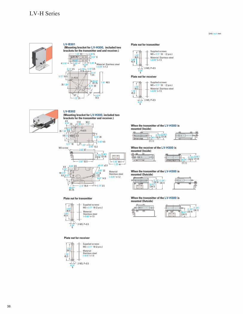
38
LV-B301 (Mounting bracket for LV-H300, included two brackets for the transmitter and and receiver.)
Plate nut for transmitter
Plate nut for receiver
0.24"6
1.78"45.3
1.55"39.3
0.24"6
1.69"42.9
1.45"36.9
14.5
1.69" 43
11
17.90.14" 3.5
35 1.38"
21
10°1.22" 31
10°
0.79" 20
3.5
6-R1.75
4-R0.07"
LV-B302 (Mounting bracket for LV-H300, included two brackets for the transmitter and receiver.)
8
1.43" 36.41.73" 44
0.71" 18
0.87" 22
0.14" 3.5
9.5
19
4.50.18" 30.2
0.18" 4.5
0.48" 12.2
35 1.38"
0.79" 20
31
17.9
2.64" 67
2.07" 52.5
(18.5)
0.14" 3.5
7°
2.18" 55.4
8.5
9.519 0.75"
0.24"6
1.78"45.3
1.55"39.3
0.24"6
1.69"42.9
1.45"36.9
C9
Plate nut for transmitter
Plate nut for receiver
(18.5)
(11.1)
(32.4)
(24.7)
0.57" 14.5
R0.07"R1.75
3.2
(21.8)
(32.4) (24.7)
(34.1)
(34.1)
M3 screw
(18.5)(11.1)
(21.8)
4-ø3.5
(21.8)
When the transmitter of the LV-H300 is mounted (Inside)
When the receiver of the LV-H300 is mounted (Inside)
When the transmitter of the LV-H300 is mounted (Outside)
When the transmitter of the LV-H300 is mounted (Outside)
Material: Stainless steel t=0.05" t=1.2
Supplied screws:M3 × 0.71" 18 …(2 pcs.)Material: Stainless steel t=0.06" t=1.5
2-M3, P=0.5
2-M3, P=0.5
2- 3.5
Material: Stainless steelt=0.05" t=1.2
ø0.14" ø3.5
2-M3, P=0.5
2-M3, P=0.5
R0.07"4 0.16" 0.83" 0.43"
0.16" 4
0.20" 50.31" 8
0.70" 0.14" 3.5
0.14"
1.91" 48.5R1.75
0.73" 18.5
0.57"
Supplied screws:M3 × 0.71" 18 …(2 pcs.)Material: Stainless steel t=0.06" t=1.5
0.70" 1.19"
1.22"
0.75"
0.37"
(0.73") (0.86")
0.33"
0.37"0.31"
Material: Stainless steelt=0.06" t=1.5
Supplied screws:M3 × 0.71" 18 (2 pcs.)
Supplied screws:M3 × 0.71" 18 (2 pcs.)
Material: Stainless steelt=0.06" t=1.5
(0.44")(0.73")(0.86")
(0.44")(0.86")(0.73")
(0.97")
(1.28") (1.34")
(0.97")(1.28") (1.34")
LV-H Series
Unit: inch mm
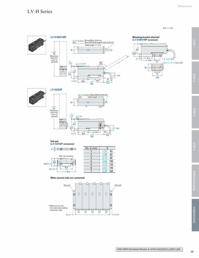
39
0.12" 3.1
1.13"28.7
1.33"33.7
28.7
1.1
35.429.4 2.94"74.6
(Maximum when the cover is opened)
0.57" 14.5
1.39" 35.429.4
1.13"28.7
1.33"33.7
5 0.20"
20 0.79"
0.94"min.
1.1
20 0.79"
151.12"28.5
0.94"min.
20 0.79"
0.57" 14.5
0.20" 5
5 0.20" 1.29" 32.71.55" 39.4
15 2-(0.17" x 0.13") (4.4 x 3.4)
(1.44")(36.5)
0.12" 3.1150°max.
End unitEnd unit
L6 0.24"
DIN-rail mounting
35.49.2 0.36"
2.12" 53.8
0.82"20.8
(22.6) (0.89")
6 0.24"
* Make sure to use end units when adding expansion units.
LNo. of units1234567
406080100120140160
Mounting bracket attached(LV-51M/51MP accessory)
LV-52/52P
LV-51M/51MP
End unit (LV-52/52P accessory)
When several units are connected:
ø0.18", 6-core x Brown/Blue: 0.34 mm2
Black/White/Orange/Purple: 0.23 mm2
2- ø0.13" ø3.4
Cable length: 6.6' 2 m
ø0.14", 2-core x Black/White: 0.23 mm2 Cable length: 6.6' 2 m
3.98"101
ø4.5
0.04"
1.13"
1.16" 1.39" 24
ø3.6
0.04"
(Maximum when the cover is opened)
3.98"101
2.94"74.6
1.16" 20
1.39"
0.24" 6
1.57"2.36"3.15"3.94"4.72"5.51"6.30"
0.59"
0.59"
LV-H Series
STEP 1STEP 3
STEP 4SPECIFICATION
SDIM
ENSION
SSTEP 2
Dimensions
CAD DATA Download Service www.keyence.com/cad
Unit: inch mm

KA1-0049
Specifications are subject to change without notice.
CALL TOLL FREE
TO CONTACT YOUR LOCAL OFFICE
1 - 8 8 8 - 5 3 9 - 3 6 2 3
Corporate Office 50 Tice Blvd., Woodcliff Lake, NJ 07677 Phone: 201-930-0100 Fax: 201-930-0099 E-mail: [email protected]
■ Regional offices COFLGAIL
DenverTampaAtlantaChicago
ALCACA
BirminghamN.CaliforniaLos Angeles
VAWA
RichmondSeattle
SCTNTNTX
GreenvilleNashvilleKnoxvilleDallas
Fax: 201-930-0099www.keyence.com
KEYENCE CORPORATION OF AMERICA
KEYENCE CANADA INC.
Head Office Phone: 905-696-9970 Fax: 905-696-8340 E-mail: [email protected] Phone: 514-694-4740 Fax: 514-694-3206
KEYENCE MEXICO S.A. DE C.V.
Phone: +52-81-8220-7900 Fax: +52-81-8220-9097 E-mail: [email protected]
INKSKYMA
IndianapolisKansas CityLouisvilleBoston
MIMIMNMO
DetroitGrand RapidsMinneapolisSt. Louis
NJNYNCNC
Woodcliff LakeRochesterCharlotteRaleigh
OHOHORPA
CincinnatiClevelandPortlandPhiladelphia
Copyright (c) 2008 KEYENCE CORPORATION. All rights reserved. LVSBG-KA-C-E 0069-3 611119 Printed in Japan
* 6 1 1 1 1 9 *


![Laser sensor ISD-5 - Riftek · 2020. 7. 28. · Laser sensor ISD-5 ISD-5 [Rev1.0] 15 Aug 2016 3 tive to fixed sensor. 1. Overview Laser speed and length sensors are intended for industrial](https://img.pdfslide.net/doc/110x75/60da295a446655343761336a/laser-sensor-isd-5-riftek-2020-7-28-laser-sensor-isd-5-isd-5-rev10-15.jpg)