Embed Size (px)
Citation preview
LAWRENCE B. KARP CONSULTING GEOTECHNICAL ENGINEER
July 10, 2019
City & County of San Francisco Board of Supervisors Legislative Chamber City Hall, Room 250 San Francisco, CA 94102
Attention: Norman Yee, President
Subject: Millennium Tower 301 Mission Street, San Francisco Two Differing Plans for Foundation Retrofitting
Dear President Y ee and Board Members:
FOUNDATIONS, WALLS, PILES UNDERPINNING, nEBACKS
DEEP RETAINED EXCAVATIONS SHORING & BULKHEADS
CEQA, EARTHWORK & SLOPES CAISSONS, COFFERDAMS
COASTAL & MARINE STRUCTURES
SOIL MECHANICS, GEOLOGY GROUNDWATER HYDROLOGY
CONCRETE TECHNOLOGY
This correspondence briefly discusses two foundation plans (external asymmetrical and internal symmetrical) engineered separately for retrofitting support to the subsided and tilted Millennium Tower. This report is provided as a public service as one of the plans seriously affects the City.
Preface
The External Asymmetrical Plan enlarges the footprint of the building by utilizing portions of Fremont and Mission streets for shoring, trenching, drilling and casing new foundation piles to support extensions of the building's substructure along part of its outside perimeter to prop the lower half of the building, which result is projected to support about one-fifth of the building's total load. The Internal Symmetrical Plan consists of jacking new piles arranged in a systematic pattern inside the building to provide new uniform support for the entire building. Piles into bedrock are used for foundation support in both plans. The final cost estimate for the completed refined internal plan is estimated to be less than the cost projected for the preliminary external plan. The cost differential will increase because the external plan requires ownership or easement use of City property in the streets, involves traffic disruptions and expenses, and because of probable damages due to dewatering and lost ground; these and other undeterminable but very significant additional direct and indirect construction costs and delays will ultimately be added as contingencies to the cost of the external plan. The internal plan is isolated and self contained within the building envelope without any participation by the City. This correspondence summarily covers, by pros and cons associated with major factors, why the internal plan is vastly superior to the external plan.
Building
The Millennium Tower is a 58 story concrete framed building' built 8/06-2/08, 645 feet high, housing 366 residences. The basement is 25 feet deep incorporating a 10 foot thick reinforced concrete mat with 920 prestressed concrete production piles, driven 4 7 to 83 feet deep through heterogeneous fill (the building is situated at the 1852 shoreline) and marine deposits such that their tips were founded in dense sands. The Tower is said to be the highest and heaviest concrete building in the western US.
100 TRES MESAS, ORINDA CA 94563 (415) 860-0791 fax: (925) 253-0101 e-mail: [email protected]
Board of Supervisors, Millennium Tower Retrofit Plans, 7/10/19 Page 2 of7
Causation
The Millennium Tower subsided due to the extraordinary overall building loads imposed upon the subgrade, and settled more differentially toward the comer of Mission and Fremont Streets due to the consequences of groundwater pwnping which lowered the phreatic surface (groundwater level) along the northwest comer of the building. Dewatering from buildings along those streets added loads to the Millennium Tower's subgrade due to loss of buoyancy by the water and increase in effective vertical stress in the sub grade. Loss of water content also causes silts and clays to compress and the additional weight of overburden soils causes clays to consolidate.
The top of the building tilts about 18 inches toward west northwest due to differential settlement of the building, which aggravates the settlement near the comer of Fremont and Mission Streets by movement of the center of gravity of the building. The differential loading and loss of support from dewatering, the greatest value where drawdown approaches the intersection of Mission and Fremont Streets, if proportioned flat from the building' s comer on Minna Street almost midway to Beale Street, from the building's height, is 4.8 inches, but the mat is dished so the actual level differential near the intersection of Fremont and Mission Streets is about 3 inches.
The comer opposite from the Fremont and Mission comer of the building, on Minna, was not dewatered directly due to a 60 foot deep cut-off wall between the properties constructed by the Transbay Transit Center from outside Beale then along Minna to Fremont. By projecting available pieziometric levels and slope of the building's base as an indicator of drawdown, there is a hydraulic gradient of the phreatic surface, which cannot be measured directly due to interference, sloping down toward the intersection of Fremont and Mission Streets. Both the excessive load of the concrete building supported by an inadequate pile system, and pumping from other construction and buildings along Mission Street that also drew down groundwater from Fremont Street, caused the subsidence and tilting of the building. The concrete substructure is cracked and broken from differential settlement and tilting of the building, which has severely compromised the heads of the existing thin (14 inch square) prestressed concrete pil~s. Dewatering along Mission Street will continue, and will probably worsen as Oceanwide Center nears completion of construction dewatering, therefore settlement of the building will continue particularly if the external plan is implemented. As deep foundation construction technology was available when the Millennium Tower was designed and built, the settlements due to the loads on the inadequate pile foundation and the loads due to dewatering that caused the tilting could have been prevented by constructing a foundation with piles reaching bedrock.
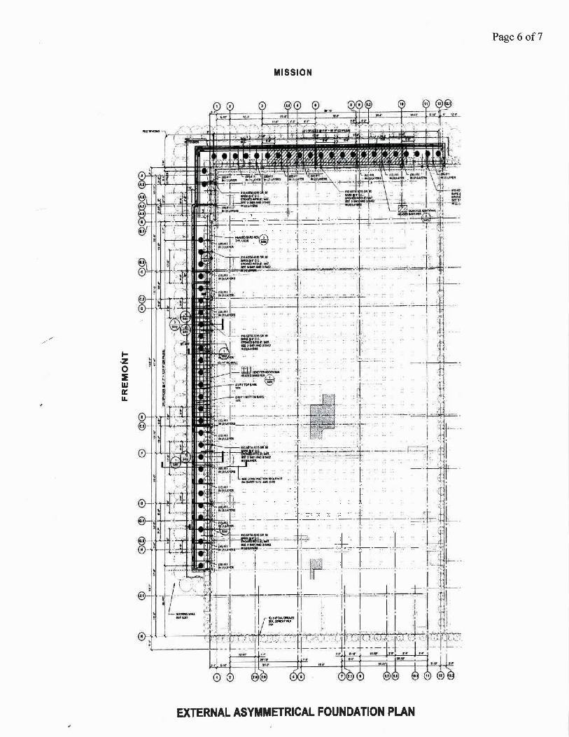
External Asymmetrical Plan
The external plan (attached schematic), designed by Simpson Gumpertz & Heger (SGH) Consulting Engineers has a total of 52 drilled and cased very closely spaced piles along Mission and Fremont Streets; 30 along Fremont and 22 along Mission that are connected by a continuous concrete pile cap that will be doweled into the existing substructure so the new piles will provide bedrock support, which will be eccentric, for about one-fifth of the building's total load.
An SPTC wall 4 7 feet deep will be built to shore a 27 foot deep, 10 foot wide excavations in both streets between the shoring and the existing substructure. A 5 foot thick grout plug will be · constructed at the bottom of the excavation to prop the shoring at excavation sub grade, restrict backslope subsidence and basal heave, and provide an area to work in the dry. Piles will be drilled from the street and cased from bedrock to the level of the mat's bottom.
LAWRENCE B. KARP CONSULTING. ENGINEER
Board of Supervisors, Millennium Tower Retrofit Plans. 7/10/19 Page 3ofT
Groundwater Table Drawdown
The major initial problem with construction of the external plan that has no realistic practical or theoretical solution is further loss of groundwater, which is likely to cause more irreparable damage to the building's substructure regardless of subsequent attempts to counter the effect of supporting the existing mat with flat jacks on the piles. Drilling, casing, and removal of spoils from the site to construct closely spaced 52 piles, 36 inch diameter holes to the top of the Old Bay Mud (80 feet below street grade) to become 24 inch diameter piles more than 200 feet deep will cause loss of ground which comes with loss of groundwater that will worsen the problem from dewatering that created the condition in the first place in the area of the planned new piles.
Exacerbating the loss of groundwater with removal from Fremont and Mission Streets of about 1,500 CY of soil and water from the combined locations of the piles will be dewatering necessary to excavate the planned 10 foot wide 27 foot deep trench, 125 feet along Mission Street and 175 feet along Fremont Street, about 3,000 CY. Present groundwater levels near the intersection of Fremont and Mission Streets are at about 23 feet from street grade. With construction of the grout plug in Young Bay Mud, the trench will require groundwater levels along Fremont and Mission Streets to be drawn down to at least 33 feet from street grade, or about 10 feet down from the present GWT.
Groundwater withdrawal without recharge lowers the groundwater table which with building loads increases overburden pressure on compressible soils. Lowering the GWT another 10 feet for the design and to create workable space in the Young Bay Mud for the grout plug will cause the building to further settle differentially with associated damages to the building's substructure .. From geometry, for every new inch of differential settlement of the Millennium Tower at Fremont and Mission Streets, the top of Millennium Tower will lean about an additional4 inches. The tilt will be unacceptable to the owners of the residences and the public. Severe increased breaking and cracking of the concrete base and rotation/failure of the pile heads due to more differential settlement will cause further irreparable damage.
Plan Configuration Irregularity
The asymmetrical external foundation plan, consisting of perimeter piles along two adjacent sides of the building, will create a major horizontal structural irregularity. This will be a torsional irregularity as the new piles are relatively strong load-resisting elements but there are no comparables on the opposite sides of the building. Earthquakes have repeatedly shown that buildings that have irregular configurations suffer greater damage; for irregular plans, torsion is caused by eccentricity between the centers of mass and rigidity. In regular structures inelastic response with energy dissipation and damage produced by strong ground shaking will be distributed throughout the building. For the external foundation plan, where a seismic event will generate base shears that are derivatives of the building's weight in precisely the direction of the new pile rows which may passively resist them, forces in other directions will cause torsion to other building elements or will not be resisted by available passive, such as along Minna Street. In such irregular structures, inelastic behavior may be concentrated. The existing 14 inch square (with chamfered comers) piles, even with tops reinforced likely have rotated heads, crushed portions of concrete, and bent bars as a result of the differential settlement of the mat foundation that was meant to tie the piles together for group action. Narrow concrete piles that are prefabricated with prestressing strands are for the purpose of resisting breakage during lifting, and with cushions to resist driving forces; their heads are not meant to rotate. Ground motions acting on a skew with respect to the building's axis can cause torsion. 2016 California Existing Building Code §403.9.4, for voluntary seismic improvements, requires that alterations do not create a structural irregularity.
LAWRENCE B. KARP CONSULTING ENGINEER
Board of Supervisors, Millennium Tower Retrofit Plans, 7 /l 0/19 Page 4 of7
City Disruption & Expense
Ifthe project is approved by the City, there seem to be questions about easement or ownership of the land that the City may grant to the Millennium Tower Association. The tiebacks for the SPTC wall will have to remain in the street area, as have the tiebacks for 301 and 350 Mission. The SPTC shoring wall, building extension, piles, and vaults will be permanent.
For the excavation into San Francisco public streets to enlarge the footprint of the Millennium Tower, 10 feet wide between the shoring wall and 300 feet long (125 feet along Mission and 175 feet along Fremont), there will have to be rerouting of underground utilities, fencing, staging area for materials, operating of excavation and drilling equipment, trucking of spoils including contaminated materials from dumping and other fills over the 1952 shoreline, which will tie up portions of two way Mission and one way Fremont up for a year or more. The Fremont off ramp from the Bay Bridge is the major entrance to downtown every weekday morning, the option of turning on Howard is awkward because of one way streets so the blocking at Fremont and Mission will be very disruptive and will have serious effects on downtown traffic. The cost of municipal vehicles, equipment, and personnel to control traffic will have to bt; borne by the City.
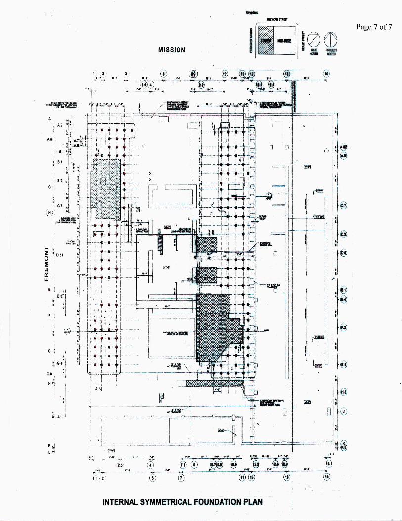
Internal Symmetrical Plan
The internal plan (attached schematic), designed by Leslie E. Robertson Associates (LERA), Consulting Structural Engineers, designer of the World Trade Center in New York, has a total of 108 new steel jacketed piles, 54 on the Fremont side and 54 on the opposite side of the building, arranged in a symmetrical longitudinal and transverse pattern that are installed inside the basement and will perform entirely within the building's footprint. The upper portions of the 13-5/8 inch. outside diameter 5/8 inch wall thickness steel rock piles are 30 feet long in and below the existing concrete mat, and inside the larger pipes are 9-5/8 inch outside diameter 1-3/8 inch wall thickness steel rock piles. The smaller piles extend through the larger piles into bedrock that is projected to be 220 feet from the bottom of the Millennium Tower mat portion of the substructure.
The entirely new pile system will provide full uniform and symmetrical vertical and lateral support for the Tower. The new lateral resistance to base shear provided by the 108 13-5/8 inch diameter piles below the mat is a much improved lateral force resisting system over the original design that relied on passive resistance against the basement wall and the prestressed concrete piles with the design assumption that the bottom of the mat substructure would remain level.
The new piles are jacked into bedrock through holes cut through the basement slab. The jacking system uses the weight of the concrete building as a reaction. Pile locations as finally set were arranged to avoid MPE utilities, computer facilities, and fire pump house. Pile s~ctions have threaded connections, there is no welding and annular space in the piles are grouted. The internal plan does not involve any dewatering and there is no drilling through soils. There is potential with the internal plan to at least partially return the substructure to a more level condition during the jacking process.
Costs
The cost to construct the external asymmetrical plan has been estimated by the media, quoting SOH, to be $1OOM, but it will be more due to the taking of City property and services, and contingencies. The cost to construct the internal symmetrical plan has gone through joint iterations by two of the nation's major deep foundation contractors after design refinements, gravitating to less than $90M; but the media reported much higher costs based on negotiation stances by lawyers, which led to development of the external plan.
LAWRENCE B. KARP CONSULTING ENGINEER
1-,z 0 :1 w 0:: u.
Page 6 of7
MISSION
EXTERNA.L ASYMMETRICAL FOUNDATION PLAN
A I , A.2' ;I
A.O· i ! B ,
I
I
J-, ~ i l 0.61
:IE w 0:: . II. I
i J.1
.., . ;
I ' 1-''':j
MISSION
3 \ lt'·r ·· J
r t _ --·
1
.- €! . ~~ I~
II ~ .w ~~ ' ,~1 t... J fo
• ••
I
l:::=:::fr= =;:::::::::=t=::-=::===l !t fj
.... @
INTERNAL SYMMETRICAL FOUNDATION .PLAN~
Page 7 of7