Embed Size (px)
Citation preview
LDM60S SERIES AC-DC LED DRIVER Application Note
V14 2014/08/25
Page 1
LDM60S
LED Power Supply Application Note
LDM60S SERIES AC-DC LED DRIVER Application Note
V14 2014/08/25
Page 2
Content
Revision History 3
1. INTRODUCTION 4
2. LDM60S LED DRIVER FEATURES 4
3. GENERAL DESCRIPTION 4
4. TECHNICAL SPECIFICATIONS 5
5. MAIN FEATURES AND FUNCTIONS 7
5.1 Operating Temperature Range 7
5.2 Over current Protection & over voltage protection 7
5.3 Over Temperature Protection 7
5.4 CC and CV mode 7
5.5 Dimming Interface 7
6. SAFETY 7
7. APPLICATIONS 7
7.1 Power De-Rating Curves 7
7.2 Power Factor & THD V.S Output current 7
7.3 Efficiency vs. Output current Curves 8
7.4 Test Set-Up 9
7.5 Output Ripple and Noise Measurement 9
7.6 EMI 9
8. MECHANICAL OUTLINE DIAGRAMS 10
8.1 LDM60S Mechanical Outline Diagrams 10
9. POTENTIOMETER FOR OUTPUT VOLTAGE/OUTPUT CURRENT ADJUSTMENT 11
10. INSTALLATION INSTRUCTION 12
10.1 The maximum number of the LDM60S that can be connected to a circuit breaker at 240V is shown as below. 12
10.2 Direct Driving Link Diagrams 12
10.3 Dimming Function Link Diagrams 12
10.4 DALI Function Link Diagrams 13
11. ORDERING INFORMATION 13
LDM60S SERIES AC-DC LED DRIVER Application Note
V14 2014/08/25
Page 3
Revision History
Revision Version Date Change Description Signature
V10 10 SEP. 2013 Release Wei-Cheng V11 19 MARCH.2014 Modify page4~10 & page 12 Wei-Cheng V12 3 Apr. 2014 Add page5 230VAC input current
& revise page7 Power Factor Wei-Cheng
V13 24 JULY 2014 ADD CV LOAD on page 5,Add input voltage at 90~305vac,modify page 10
Wei-Cheng
V14 25 AUGUST 2014 Revise No Load Consumption 1.5W Wei-Cheng
LDM60S SERIES AC-DC LED DRIVER Application Note
V14 2014/08/25
Page 4
1. Introduction This application note describes the features and functions of Cincon’s
LDM60S series, Isolated AC-DC led driver. These are highly efficient,
reliable and compact, high power density, single output AC/DC led
driver. The modules are fully protected against short circuit and over-
voltage conditions. Cincon’s world class automated manufacturing
methods, together with an extensive testing and qualification program;
ensure that all LDM60S series led drivers are extremely reliable.
2. LDM60S LED Driver Features • Universal Input : 90 ~ 305Vac or 127~420Vdc
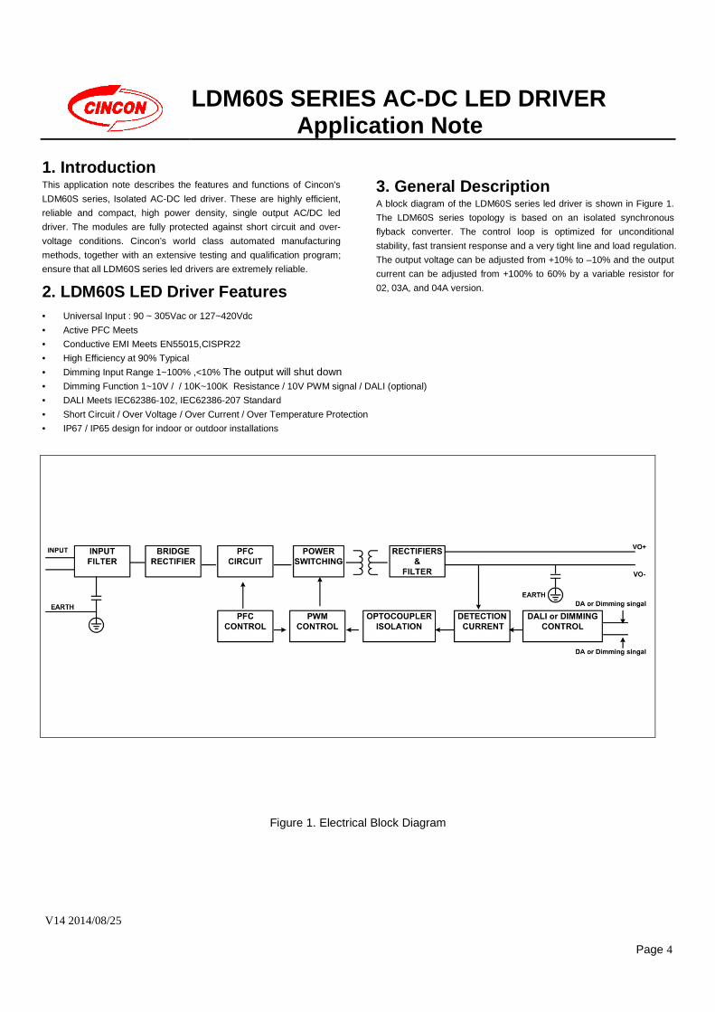
3. General Description A block diagram of the LDM60S series led driver is shown in Figure 1.
The LDM60S series topology is based on an isolated synchronous
flyback converter. The control loop is optimized for unconditional
stability, fast transient response and a very tight line and load regulation.
The output voltage can be adjusted from +10% to –10% and the output
current can be adjusted from +100% to 60% by a variable resistor for
02, 03A, and 04A version.
• Active PFC Meets
• Conductive EMI Meets EN55015,CISPR22
• High Efficiency at 90% Typical
• Dimming Input Range 1~100% ,<10% The output will shut down
• Dimming Function 1~10V / / 10K~100K Resistance / 10V PWM signal / DALI (optional)
• DALI Meets IEC62386-102, IEC62386-207 Standard
• Short Circuit / Over Voltage / Over Current / Over Temperature Protection
• IP67 / IP65 design for indoor or outdoor installations
Figure 1. Electrical Block Diagram

LDM60S SERIES AC-DC LED DRIVER Application Note
V14 2014/08/25
Page 5
4. Technical Specifications (All specifications are typical at 25and full load, unless otherwise noted.) PARAMETER NOTES and CONDITIONS Device Min. Typical Max. Units ABSOLUTE MAXIMUM RATINGS
Input Voltage 90
127
305
420
Vac
Vdc
Operating Temperature -40 +70
Storage Temperature -40 +85
Input/Output Isolation Voltage 1 minute 3750 Vac
INPUT CHARACTERISTICS
Operating Voltage Range 100 277 Vac
Input Frequency Range 50 60 Hz
Input Current Input voltage is 110Vac,Pout=59W
Input voltage is 230Vac,Pout=59W
0.6
0.31 A
Power factor correction (see Section 7.2 Power Factor & THD V.S Output
current) 0.9
Leakage Current Maximum Input voltage is 277Vac 0.75 mA
Inrush Current Input voltage is 110Vac and 240Vac, cold start at
250C. 60 A
OUTPUT CHARACTERISTIC
Output Voltage Set Point Input voltage is 115Vac and 230Vac, 90% output
current at ambient temperature 25
LDM60S120
LDM60S240
LDM60S360
LDM60S480
11.88
23.76
35.64
47.52
12
24
36
48
12.12
24.24
36.36
48.48
Vdc
Output Voltage Adjustment Output voltage*output current ≦ Rated output power(60W) (Model : LDM60SXXX-02, -03A, -04A.)
LDM60S120
LDM60S240
LDM60S360 LDM60S480
10.88
21.6
32.4
43.2
12
24
36
48
13.2
26.4
39.6
52.8
Vdc
Constant Current Region Output Voltage
LDM60S120
LDM60S240
LDM60S360
LDM60S480
6.5
13
19
26
12
24
36
48
Vdc
Output Current Constant voltage
CV LOAD =10V LDM60S120
5
2.5
1.67
1.25
A CV LOAD =20V LDM60S240
CV LOAD =30V LDM60S360
CV LOAD =40V LDM60S480
Output Current Adjustment Output voltage*output current ≦ Rated output power(60W) Model : LDM60SXXX-02, -03A, -04A.
LDM60S120
LDM60S240
LDM60S360
LDM60S480
3
1.5
1
0.75
5
2.5
1.67
1.25
A
Output Constant Current Accuracy -5 +5 %
No Load Consumption Input voltage is 230Vac 1.5 Watt
Start-up Time Input voltage is 90~305Vac 2.5 S
Rise Time Input voltage is 90~305Vac 50 mS
Holdup Time Input voltage is is 115Vac 16 mS
Load Regulation Input voltage is 115Vac and 230Vac,10% output
current to 90%l output current ±2.0 %
Line Regulation Input voltage is 90~305Vac with 90% output current
±1.0 %

LDM60S SERIES AC-DC LED DRIVER Application Note
V14 2014/08/25
Page 6
PARAMETER NOTES and CONDITIONS Device Min. Typical Max. Units
Output Voltage Ripple and Noise peak to peak 20MHz bandwidth , Full load, 0.1uF ceramic and
10uF E.L capacitor with 95% output current
LDM60S120
LDM60S240
LDM60S360
LDM60S480
120
120
120
120
mV
EFFICIENCY
95% output current
LDM60S120
LDM60S240
LDM60S360
LDM60S480
87
88
89
90
%
ISOLATION CHARACTERISTICS
Input to Output 1 minute 3750 Vac
Input to Earth 1 minute 1875 Vac
Output to Earth 1 minute 500 Vac
Isolation Resistance 100 MΩ
FEATURE CHARACTERISTICS
Switching Frequency 100% Output Current 75 KHz
Surge EN61000-4-2 Criteria A ±4 KV
Harmonic EN61000-3-2 Class C ≧( 60% output current)
GENERAL SPECIFICATIONS
Life time Ambient temperature is 25 40000 Hour
MTBF Ambient temperature is 25 per MIL-HDBK-217F 150 k hours Weight 454 g Dimension 40*207*28mm ((W*L*H)
LDM60S SERIES AC-DC LED DRIVER Application Note
V14 2014/08/25
Page 7
5. Main Features and Functions 5.1 Operating Temperature Range
The LDM60S series led driver highly efficient converter design has
resulted in its ability to operate ambient temperature environment (-
40 to 70 ). Due consideration must be given to the de -rating curves
when ascertaining maximum power that can be drawn from the
converter. The maximum power drawn is influenced by a number of
factors, such as:
• Input voltage range.
• Permissible Output load (per derating curve)
5.2 Over current Protection & over voltage protection
The power modules provide full continuous short-circuit protection. The
unit will auto recover once the short circuit is removed. To provide
protection in a fault condition, the unit is equipped with internal over-
current protection. The unit will operate normally once the fault
condition is removed. The output voltage will decrease when the output
current is above its constant current point. When the output current is
continue increase the power module will go to hiccup mode if the output
voltage is lower than 50% of rated output voltage.
All different voltage models have a full continuous over voltage
protection. The power module will supply up to 115%~135% of rated
voltage. In the event of an over voltage converter will be clamped by a
TVS component. The module will automatically restart after he fault
condition is removed.
5.3 Over Temperature Protection
The LDM60S has an over temperature protection circuit to safeguard against thermal damage. When the TH2 temperature rises above 110 , the LDM60S will shut down (latch) to protect it from overheating. 5.4 CC and CV mode
Figure 2 CC/CV mode The latest design from LDM60S takes the two mode of operation and
combines them onto one design. Figure2 you can see how the unit
will initially behave as a constant voltage unit. Once the max output
current is reached, the control loop will then hold the supply current
at a constant value and reduce the output voltage accordingly. This
type of approach has many benefits to the end designer in that if
chosen correctly both CC and CV mode designs can be achievable
with one supply.
5.5 Dimming Interface
Dimming controller is capable of driving 03 or 03A version, require 0.15mA each unit.
6. Safety CB Approval (IEC/EN61347-1,IEC/EN61347-2-13)
VDE Approval
UL Approval (UL8750)
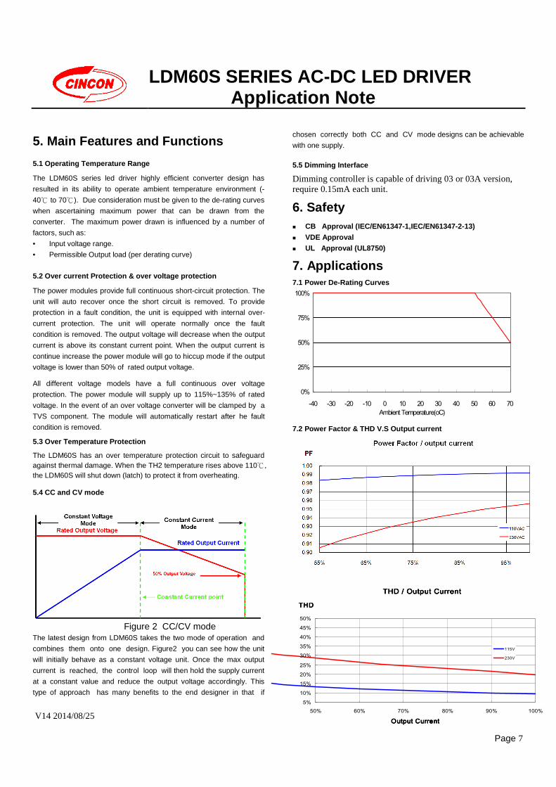
7. Applications 7.1 Power De-Rating Curves
7.2 Power Factor & THD V.S Output current
0%
25%
50%
75%
100%
-40 -30 -20 -10 0 10 20 30 40 50 60 70Ambient Temperature(oC)
THD / Output CurrentTHD / Output CurrentTHD / Output CurrentTHD / Output Current
5%10%15%20%25%
30%35%40%45%50%
50% 60% 70% 80% 90% 100%
Output CurrentOutput CurrentOutput CurrentOutput Current
THDTHDTHDTHD
115V
230V
LDM60S SERIES AC-DC LED DRIVER Application Note
V14 2014/08/25
Page 8
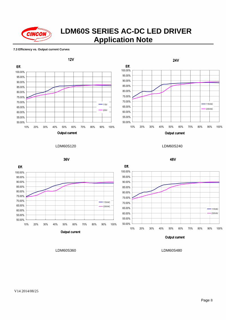
7.3 Efficiency vs. Output current Curves
12V12V12V12V
50.00%55.00%
60.00%65.00%
70.00%75.00%
80.00%85.00%90.00%
95.00%100.00%
10% 20% 30% 40% 50% 60% 70% 80% 90% 100%
Output currentOutput currentOutput currentOutput current
Eff.Eff.Eff.Eff.
115V
230V
24V24V24V24V
50.00%
55.00%
60.00%
65.00%
70.00%
75.00%
80.00%
85.00%
90.00%
95.00%
100.00%
10% 20% 30% 40% 50% 60% 70% 80% 90% 100%
Output currentOutput currentOutput currentOutput current
Eff.Eff.Eff.Eff.
115VAC
230VAC
LDM60S120 LDM60S240
36V36V36V36V
50.00%55.00%60.00%65.00%70.00%75.00%80.00%85.00%90.00%95.00%
100.00%
10% 20% 30% 40% 50% 60% 70% 80% 90% 100%
Output currentOutput currentOutput currentOutput current
Eff.Eff.Eff.Eff.
115VAC
230VAC
48V48V48V48V
50.00%
55.00%
60.00%
65.00%
70.00%
75.00%
80.00%
85.00%
90.00%
95.00%
100.00%
10% 20% 30% 40% 50% 60% 70% 80% 90% 100%
Output currentOutput currentOutput currentOutput current
Eff.Eff.Eff.Eff.
115VAC
230VAV
LDM60S360 LDM60S480
LDM60S SERIES AC-DC LED DRIVER Application Note
V14 2014/08/25
Page 9
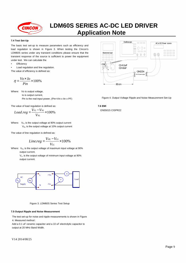
7.4 Test Set-Up
The basic test set-up to measure parameters such as efficiency and
load regulation is shown in Figure 3. When testing the Cincon’s
LDM60S series under any transient conditions please ensure that the
transient response of the source is sufficient to power the equipment
under test. We can calculate the
• Efficiency
• Load regulation and line regulation.
The value of efficiency is defined as:
%100××=Pin
IoVoη
Where: Vo is output voltage,
Io is output current,
Pin is the real input power, (Pin=Vin x Iin x PF)
The value of load regulation is defined as:
%100. ×−=NL
NLFL
V
VVregLoad
Where: VFL is the output voltage at 90% output current
VNL is the output voltage at 10% output current
The value of line regulation is defined as:
%100. ×−=
LL
LLHL
V
VVregLine
Where: VHL is the output voltage of maximum input voltage at 90%
output current.
VLL is the output voltage of minimum input voltage at 90%
output current.
V
A
LoadAC
Supply
+Vo
-Vo
L
N
Pin
Figure 3. LDM60S Series Test Setup
7.5 Output Ripple and Noise Measurement
The test set-up for noise and ripple measurements is shown in Figure
4. Measured method :
Add a 0.1 uF ceramic capacitor and a 10 uF electrolytic capacitor to
output at 20 MHz Band Width.
CINCONAC-DC power supply
80 cm
- +C1
. . C1=0.1uFC2=10uF
Output
C2
Electronic load
OscilloscopeInput
AC or DC Power source
Figure 4. Output Voltage Ripple and Noise Measurement Set-Up
7.6 EMI
EN55015 CISPR22
LDM60S SERIES AC-DC LED DRIVER Application Note
V14 2014/08/25
Page 10
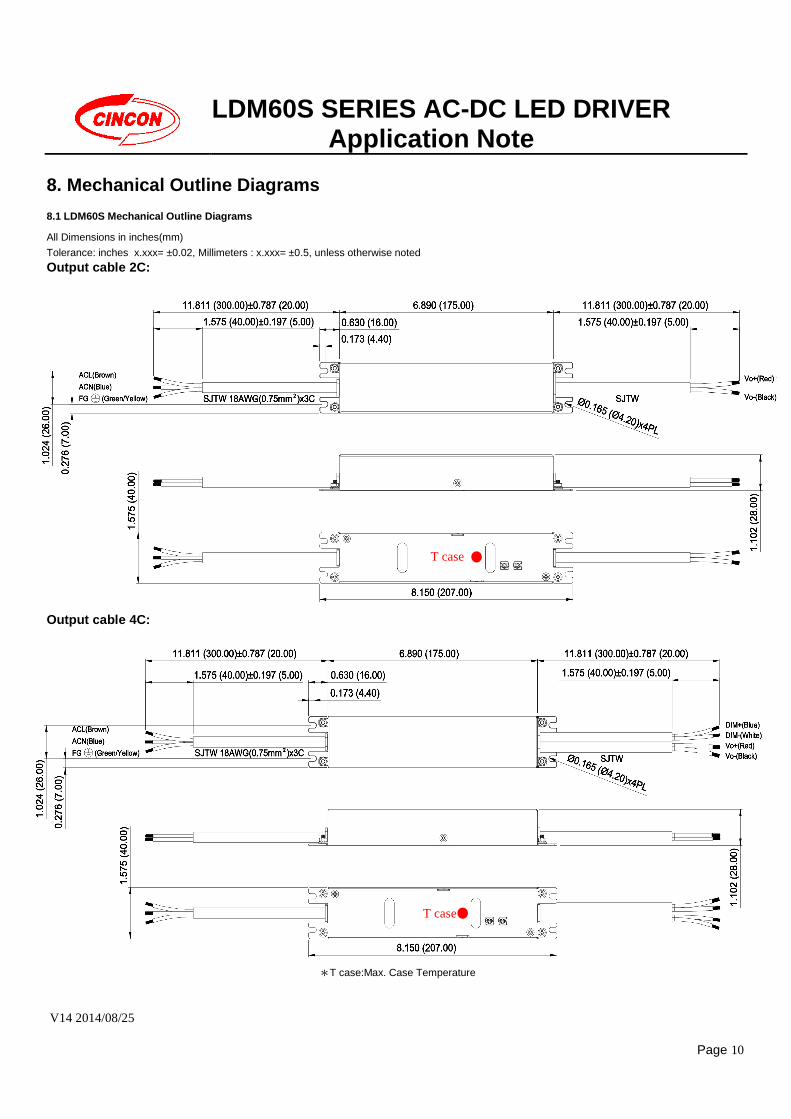
8. Mechanical Outline Diagrams 8.1 LDM60S Mechanical Outline Diagrams
All Dimensions in inches(mm)
Tolerance: inches x.xxx= ±0.02, Millimeters : x.xxx= ±0.5, unless otherwise noted
Output cable 2C:
Output cable 4C:
*T case:Max. Case Temperature
T case
T case
LDM60S SERIES AC-DC LED DRIVER Application Note
V14 2014/08/25
Page 11
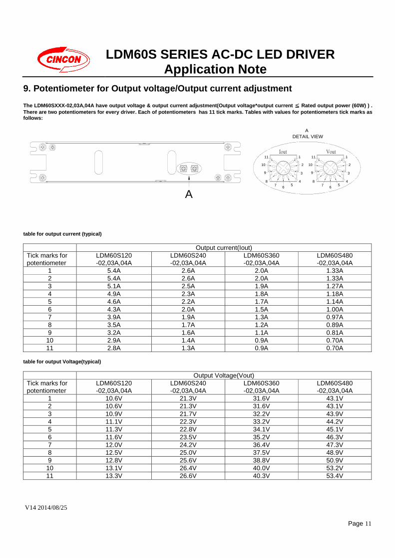
9. Potentiometer for Output voltage/Output current adjustment
The LDM60SXXX-02,03A,04A have output voltage & output current adjustment(Output voltage*output current ≦≦≦≦ Rated output power (60W) ) . There are two potentiometers for every driver. Each of potentiometers has 11 tick marks. Tables with values for potentiometers tick marks as follows:
A
Iout Vout
A DETAIL VIEW
11
10
9
87 6
1
2
3
45
11
10
9
87 6
1
2
3
45
table for output current (typical)
Output current(Iout) Tick marks for potentiometer
LDM60S120 -02,03A,04A
LDM60S240 -02,03A,04A
LDM60S360 -02,03A,04A
LDM60S480 -02,03A,04A
1 5.4A 2.6A 2.0A 1.33A 2 5.4A 2.6A 2.0A 1.33A 3 5.1A 2.5A 1.9A 1.27A 4 4.9A 2.3A 1.8A 1.18A 5 4.6A 2.2A 1.7A 1.14A 6 4.3A 2.0A 1.5A 1.00A 7 3.9A 1.9A 1.3A 0.97A 8 3.5A 1.7A 1.2A 0.89A 9 3.2A 1.6A 1.1A 0.81A
10 2.9A 1.4A 0.9A 0.70A 11 2.8A 1.3A 0.9A 0.70A
table for output Voltage(typical)
Output Voltage(Vout) Tick marks for potentiometer
LDM60S120 -02,03A,04A
LDM60S240 -02,03A,04A
LDM60S360 -02,03A,04A
LDM60S480 -02,03A,04A
1 10.6V 21.3V 31.6V 43.1V 2 10.6V 21.3V 31.6V 43.1V 3 10.9V 21.7V 32.2V 43.9V 4 11.1V 22.3V 33.2V 44.2V 5 11.3V 22.8V 34.1V 45.1V 6 11.6V 23.5V 35.2V 46.3V 7 12.0V 24.2V 36.4V 47.3V 8 12.5V 25.0V 37.5V 48.9V 9 12.8V 25.6V 38.8V 50.9V
10 13.1V 26.4V 40.0V 53.2V 11 13.3V 26.6V 40.3V 53.4V
LDM60S SERIES AC-DC LED DRIVER Application Note
V14 2014/08/25
Page 12
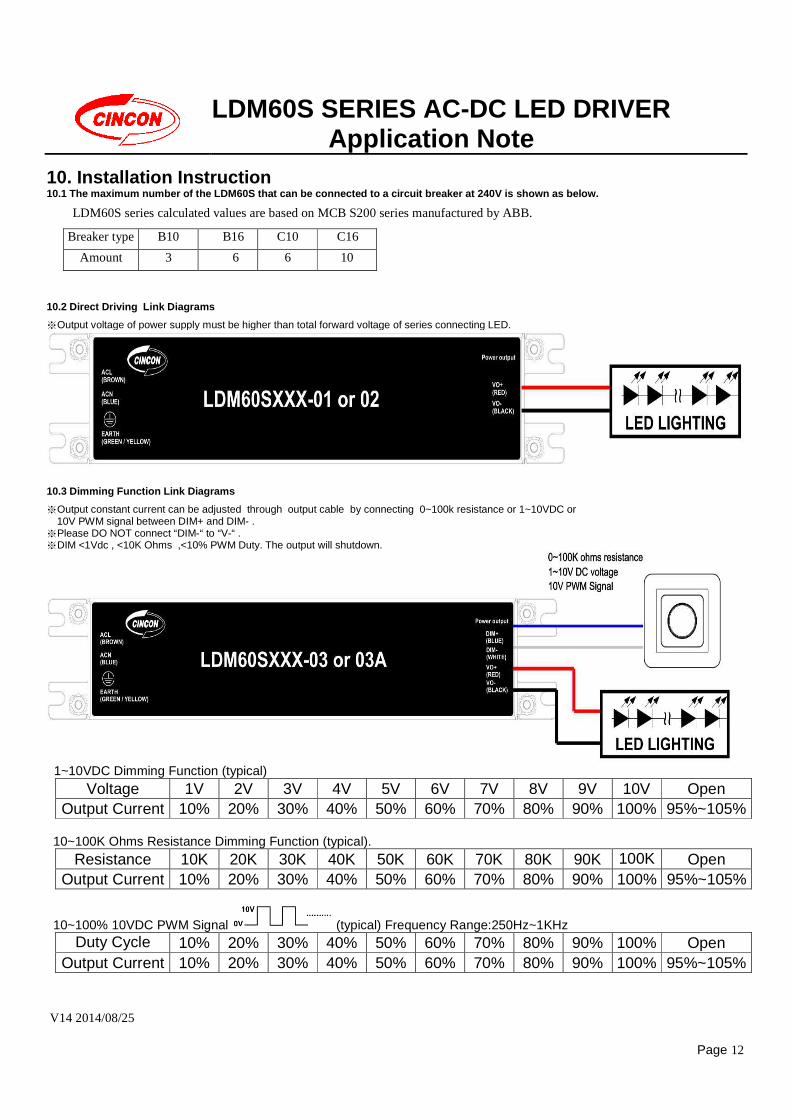
10. Installation Instruction 10.1 The maximum number of the LDM60S that can be connected to a circuit breaker at 240V is shown as below.
LDM60S series calculated values are based on MCB S200 series manufactured by ABB.
10.2 Direct Driving Link Diagrams
※Output voltage of power supply must be higher than total forward voltage of series connecting LED.
10.3 Dimming Function Link Diagrams
※Output constant current can be adjusted through output cable by connecting 0~100k resistance or 1~10VDC or 10V PWM signal between DIM+ and DIM- .
※Please DO NOT connect “DIM-“ to “V-“ . ※DIM <1Vdc , <10K Ohms ,<10% PWM Duty. The output will shutdown.
1~10VDC Dimming Function (typical)
Voltage 1V 2V 3V 4V 5V 6V 7V 8V 9V 10V Open Output Current 10% 20% 30% 40% 50% 60% 70% 80% 90% 100% 95%~105%
10~100K Ohms Resistance Dimming Function (typical).
Resistance 10K 20K 30K 40K 50K 60K 70K 80K 90K 100K Open Output Current 10% 20% 30% 40% 50% 60% 70% 80% 90% 100% 95%~105%
10~100% 10VDC PWM Signal (typical) Frequency Range:250Hz~1KHz Duty Cycle 10% 20% 30% 40% 50% 60% 70% 80% 90% 100% Open
Output Current 10% 20% 30% 40% 50% 60% 70% 80% 90% 100% 95%~105%
Breaker type B10 B16 C10 C16
Amount 3 6 6 10
LDM60S SERIES AC-DC LED DRIVER Application Note
V14 2014/08/25
Page 13
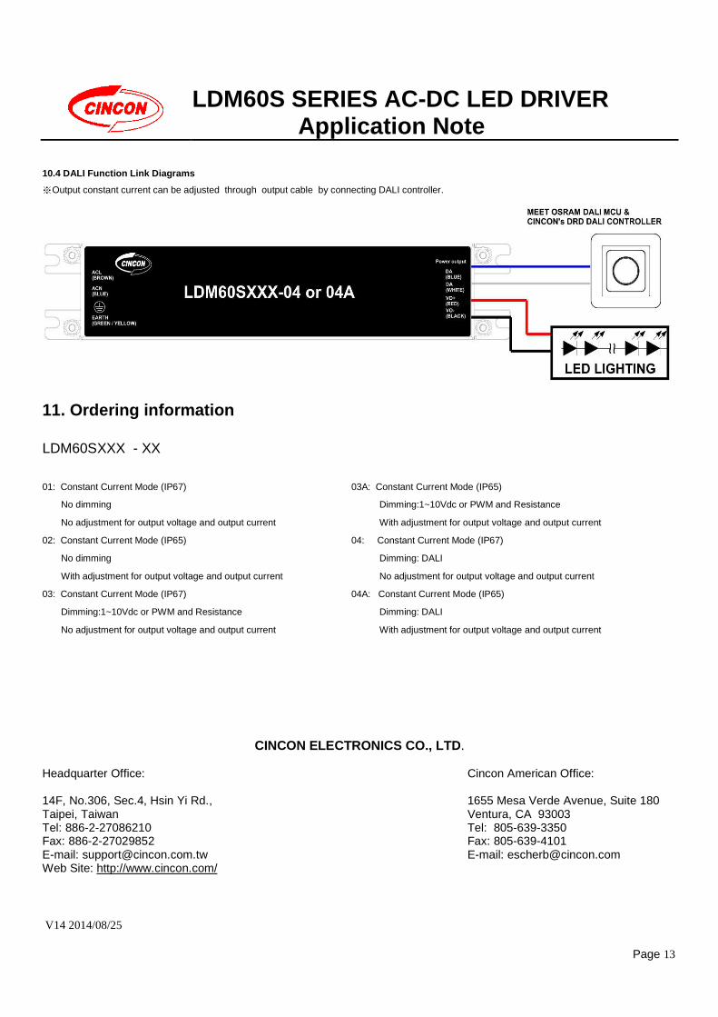
10.4 DALI Function Link Diagrams
※ Output constant current can be adjusted through output cable by connecting DALI controller.
11. Ordering information
LDM60SXXX - XX
01: Constant Current Mode (IP67)
No dimming
No adjustment for output voltage and output current
02: Constant Current Mode (IP65)
No dimming
With adjustment for output voltage and output current
03: Constant Current Mode (IP67)
Dimming:1~10Vdc or PWM and Resistance
No adjustment for output voltage and output current
03A: Constant Current Mode (IP65)
Dimming:1~10Vdc or PWM and Resistance
With adjustment for output voltage and output current
04: Constant Current Mode (IP67)
Dimming: DALI
No adjustment for output voltage and output current
04A: Constant Current Mode (IP65)
Dimming: DALI
With adjustment for output voltage and output current
CINCON ELECTRONICS CO., LTD.
Headquarter Office: 14F, No.306, Sec.4, Hsin Yi Rd., Taipei, Taiwan Tel: 886-2-27086210 Fax: 886-2-27029852 E-mail: [email protected] Web Site: http://www.cincon.com/
Cincon American Office: 1655 Mesa Verde Avenue, Suite 180 Ventura, CA 93003 Tel: 805-639-3350 Fax: 805-639-4101 E-mail: [email protected]