Embed Size (px)
Citation preview
Lecture 2: Geometrical Optics
Outline
1 Geometrical Approximation2 Lenses3 Mirrors4 Optical Systems5 Images and Pupils6 Aberrations
Christoph U. Keller, Leiden Observatory, [email protected] Lecture 2: Geometrical Optics 1
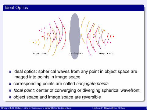
Ideal Optics
ideal optics: spherical waves from any point in object space areimaged into points in image spacecorresponding points are called conjugate pointsfocal point: center of converging or diverging spherical wavefrontobject space and image space are reversible
Christoph U. Keller, Leiden Observatory, [email protected] Lecture 2: Geometrical Optics 2
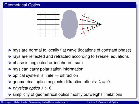
Geometrical Optics
rays are normal to locally flat wave (locations of constant phase)rays are reflected and refracted according to Fresnel equationsphase is neglected⇒ incoherent sumrays can carry polarization informationoptical system is finite⇒ diffractiongeometrical optics neglects diffraction effects: λ⇒ 0physical optics λ > 0simplicity of geometrical optics mostly outweighs limitations
Christoph U. Keller, Leiden Observatory, [email protected] Lecture 2: Geometrical Optics 3
Lenses
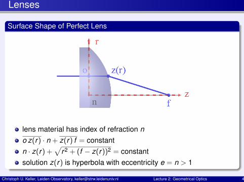
Surface Shape of Perfect Lens
lens material has index of refraction no z(r) · n + z(r) f = constantn · z(r) +
√r2 + (f − z(r))2 = constant
solution z(r) is hyperbola with eccentricity e = n > 1
Christoph U. Keller, Leiden Observatory, [email protected] Lecture 2: Geometrical Optics 4
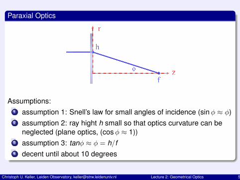
Paraxial Optics
Assumptions:1 assumption 1: Snell’s law for small angles of incidence (sinφ ≈ φ)2 assumption 2: ray hight h small so that optics curvature can be
neglected (plane optics, (cosφ ≈ 1))3 assumption 3: tanφ ≈ φ = h/f4 decent until about 10 degrees
Christoph U. Keller, Leiden Observatory, [email protected] Lecture 2: Geometrical Optics 5
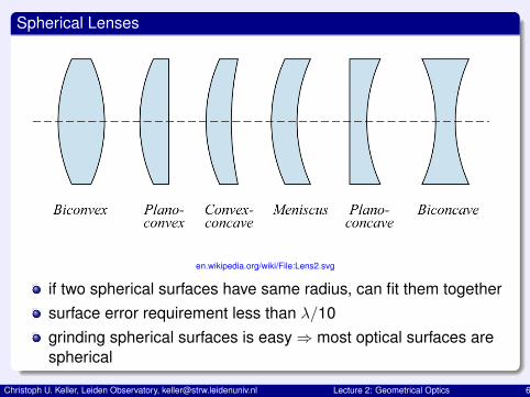
Spherical Lenses
en.wikipedia.org/wiki/File:Lens2.svg
if two spherical surfaces have same radius, can fit them togethersurface error requirement less than λ/10grinding spherical surfaces is easy⇒ most optical surfaces arespherical
Christoph U. Keller, Leiden Observatory, [email protected] Lecture 2: Geometrical Optics 6
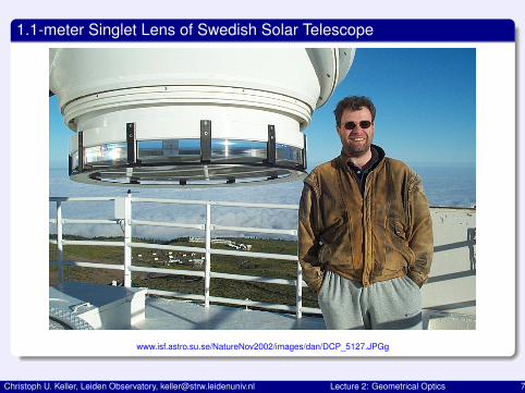
1.1-meter Singlet Lens of Swedish Solar Telescope
www.isf.astro.su.se/NatureNov2002/images/dan/DCP_5127.JPGg
Christoph U. Keller, Leiden Observatory, [email protected] Lecture 2: Geometrical Optics 7
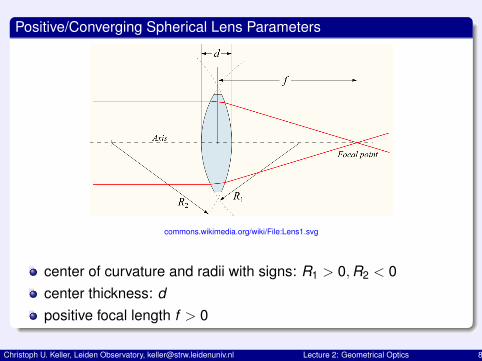
Positive/Converging Spherical Lens Parameters
commons.wikimedia.org/wiki/File:Lens1.svg
center of curvature and radii with signs: R1 > 0,R2 < 0center thickness: dpositive focal length f > 0
Christoph U. Keller, Leiden Observatory, [email protected] Lecture 2: Geometrical Optics 8
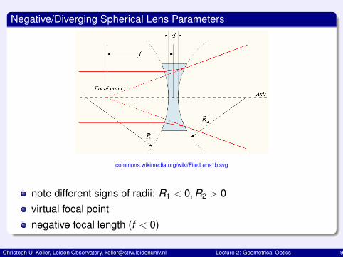
Negative/Diverging Spherical Lens Parameters
commons.wikimedia.org/wiki/File:Lens1b.svg
note different signs of radii: R1 < 0,R2 > 0virtual focal pointnegative focal length (f < 0)
Christoph U. Keller, Leiden Observatory, [email protected] Lecture 2: Geometrical Optics 9
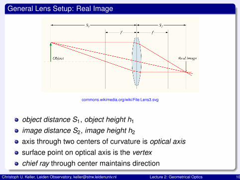
General Lens Setup: Real Image
commons.wikimedia.org/wiki/File:Lens3.svg
object distance S1, object height h1
image distance S2, image height h2
axis through two centers of curvature is optical axissurface point on optical axis is the vertexchief ray through center maintains direction
Christoph U. Keller, Leiden Observatory, [email protected] Lecture 2: Geometrical Optics 10
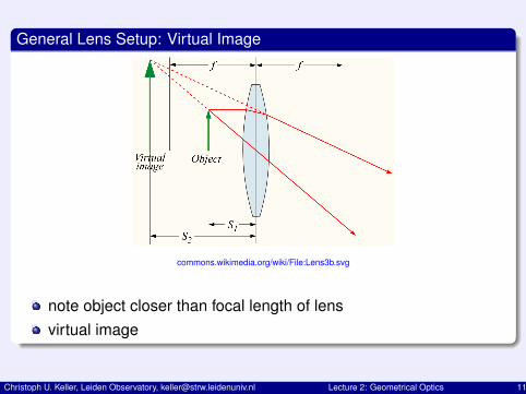
General Lens Setup: Virtual Image
commons.wikimedia.org/wiki/File:Lens3b.svg
note object closer than focal length of lensvirtual image
Christoph U. Keller, Leiden Observatory, [email protected] Lecture 2: Geometrical Optics 11
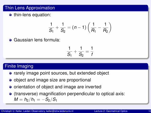
Thin Lens Approximationthin-lens equation:
1S1
+1
S2= (n − 1)
(1
R1− 1
R2
)Gaussian lens formula:
1S1
+1
S2=
1f
Finite Imagingrarely image point sources, but extended objectobject and image size are proportionalorientation of object and image are inverted(transverse) magnification perpendicular to optical axis:M = h2/h1 = −S2/S1
Christoph U. Keller, Leiden Observatory, [email protected] Lecture 2: Geometrical Optics 12
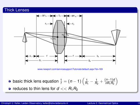
Thick Lenses
www.newport.com/servicesupport/Tutorials/default.aspx?id=169
basic thick lens equation 1f = (n − 1)
(1
R1− 1
R2+ (n−1)d
nR1R2
)reduces to thin lens for d << R1R2
Christoph U. Keller, Leiden Observatory, [email protected] Lecture 2: Geometrical Optics 13
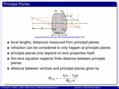
Principal Planes
hyperphysics.phy-astr.gsu.edu/hbase/geoopt/priplan.html
focal lengths, distances measured from principal planesrefraction can be considered to only happen at principle planesprinciple planes only depend on lens properties itselfthin lens equation neglects finite distance between principleplanesdistance between vertices and principal planes given by
H1,2 = − f (n − 1)dR2,1n
Christoph U. Keller, Leiden Observatory, [email protected] Lecture 2: Geometrical Optics 14
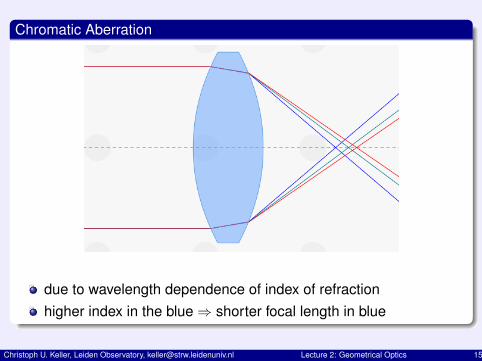
Chromatic Aberration
due to wavelength dependence of index of refractionhigher index in the blue⇒ shorter focal length in blue
Christoph U. Keller, Leiden Observatory, [email protected] Lecture 2: Geometrical Optics 15
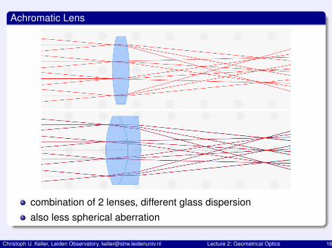
Achromatic Lens
combination of 2 lenses, different glass dispersionalso less spherical aberration
Christoph U. Keller, Leiden Observatory, [email protected] Lecture 2: Geometrical Optics 16
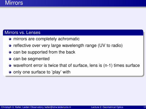
Mirrors
Mirrors vs. Lensesmirrors are completely achromaticreflective over very large wavelength range (UV to radio)can be supported from the backcan be segmentedwavefront error is twice that of surface, lens is (n-1) times surfaceonly one surface to ’play’ with
Christoph U. Keller, Leiden Observatory, [email protected] Lecture 2: Geometrical Optics 17
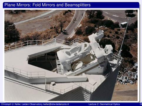
Plane Mirrors: Fold Mirrors and Beamsplitters
Christoph U. Keller, Leiden Observatory, [email protected] Lecture 2: Geometrical Optics 18
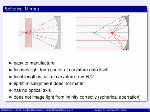
Spherical Mirrors
easy to manufacturefocuses light from center of curvature onto itselffocal length is half of curvature: f = R/2tip-tilt misalignment does not matterhas no optical axisdoes not image light from infinity correctly (spherical aberration)
Christoph U. Keller, Leiden Observatory, [email protected] Lecture 2: Geometrical Optics 19
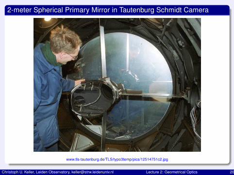
2-meter Spherical Primary Mirror in Tautenburg Schmidt Camera
www.tls-tautenburg.de/TLS/typo3temp/pics/12514751c2.jpg
Christoph U. Keller, Leiden Observatory, [email protected] Lecture 2: Geometrical Optics 20
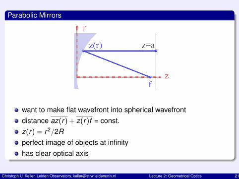
Parabolic Mirrors
want to make flat wavefront into spherical wavefrontdistance az(r) + z(r)f = const.z(r) = r2/2Rperfect image of objects at infinityhas clear optical axis
Christoph U. Keller, Leiden Observatory, [email protected] Lecture 2: Geometrical Optics 21
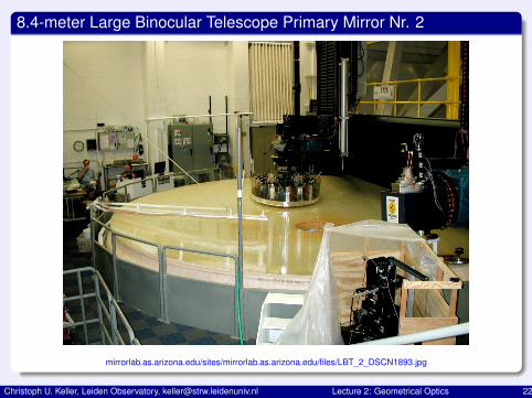
8.4-meter Large Binocular Telescope Primary Mirror Nr. 2
mirrorlab.as.arizona.edu/sites/mirrorlab.as.arizona.edu/files/LBT_2_DSCN1893.jpg
Christoph U. Keller, Leiden Observatory, [email protected] Lecture 2: Geometrical Optics 22
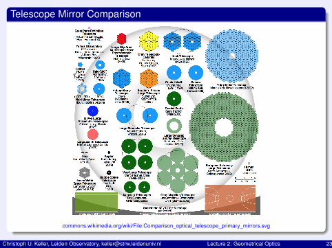
Telescope Mirror Comparison
commons.wikimedia.org/wiki/File:Comparison_optical_telescope_primary_mirrors.svg
Christoph U. Keller, Leiden Observatory, [email protected] Lecture 2: Geometrical Optics 23
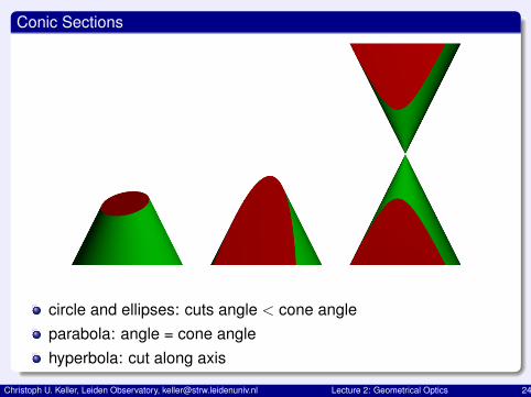
Conic Sections
circle and ellipses: cuts angle < cone angleparabola: angle = cone anglehyperbola: cut along axis
Christoph U. Keller, Leiden Observatory, [email protected] Lecture 2: Geometrical Optics 24
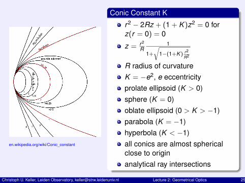
en.wikipedia.org/wiki/Conic_constant
Conic Constant K
r2 − 2Rz + (1 + K )z2 = 0 forz(r = 0) = 0
z = r2
R1
1+√
1−(1+K ) r2
R2
R radius of curvatureK = −e2, e eccentricityprolate ellipsoid (K > 0)sphere (K = 0)oblate ellipsoid (0 > K > −1)parabola (K = −1)hyperbola (K < −1)all conics are almost sphericalclose to originanalytical ray intersections
Christoph U. Keller, Leiden Observatory, [email protected] Lecture 2: Geometrical Optics 25
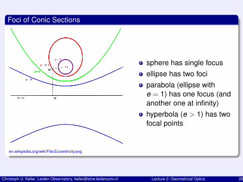
Foci of Conic Sections
en.wikipedia.org/wiki/File:Eccentricity.svg
sphere has single focusellipse has two fociparabola (ellipse withe = 1) has one focus (andanother one at infinity)hyperbola (e > 1) has twofocal points
Christoph U. Keller, Leiden Observatory, [email protected] Lecture 2: Geometrical Optics 26
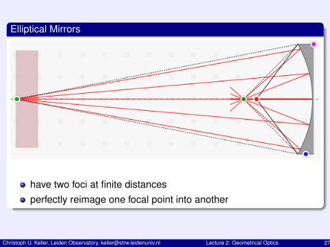
Elliptical Mirrors
have two foci at finite distancesperfectly reimage one focal point into another
Christoph U. Keller, Leiden Observatory, [email protected] Lecture 2: Geometrical Optics 27
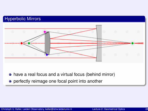
Hyperbolic Mirrors
have a real focus and a virtual focus (behind mirror)perfectly reimage one focal point into another
Christoph U. Keller, Leiden Observatory, [email protected] Lecture 2: Geometrical Optics 28
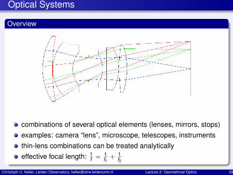
Optical Systems
Overview
combinations of several optical elements (lenses, mirrors, stops)examples: camera “lens”, microscope, telescopes, instrumentsthin-lens combinations can be treated analyticallyeffective focal length: 1
f = 1f1+ 1
f2
Christoph U. Keller, Leiden Observatory, [email protected] Lecture 2: Geometrical Optics 29
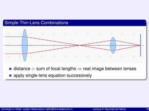
Simple Thin-Lens Combinations
distance > sum of focal lengths⇒ real image between lensesapply single-lens equation successively
Christoph U. Keller, Leiden Observatory, [email protected] Lecture 2: Geometrical Optics 30
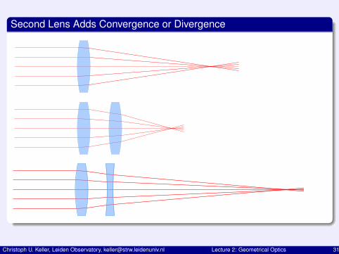
Second Lens Adds Convergence or Divergence
Christoph U. Keller, Leiden Observatory, [email protected] Lecture 2: Geometrical Optics 31
F-number and Numerical Aperture
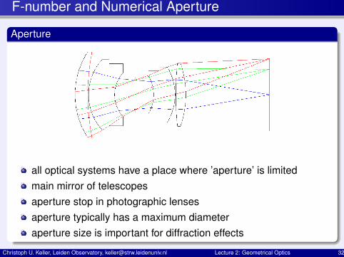
Aperture
all optical systems have a place where ’aperture’ is limitedmain mirror of telescopesaperture stop in photographic lensesaperture typically has a maximum diameteraperture size is important for diffraction effects
Christoph U. Keller, Leiden Observatory, [email protected] Lecture 2: Geometrical Optics 32
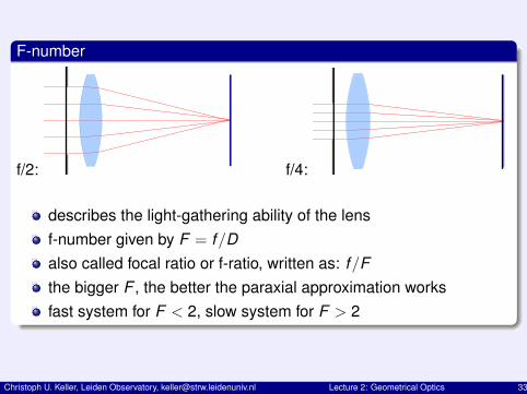
F-number
f/2: f/4:
describes the light-gathering ability of the lensf-number given by F = f/Dalso called focal ratio or f-ratio, written as: f/Fthe bigger F , the better the paraxial approximation worksfast system for F < 2, slow system for F > 2
Christoph U. Keller, Leiden Observatory, [email protected] Lecture 2: Geometrical Optics 33
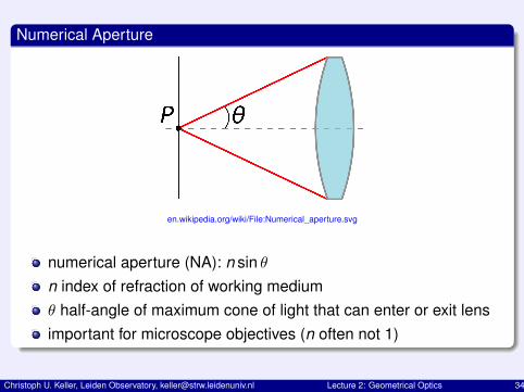
Numerical Aperture
en.wikipedia.org/wiki/File:Numerical_aperture.svg
numerical aperture (NA): n sin θn index of refraction of working mediumθ half-angle of maximum cone of light that can enter or exit lensimportant for microscope objectives (n often not 1)
Christoph U. Keller, Leiden Observatory, [email protected] Lecture 2: Geometrical Optics 34
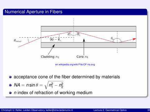
Numerical Aperture in Fibers
en.wikipedia.org/wiki/File:OF-na.svg
acceptance cone of the fiber determined by materials
NA = n sin θ =√
n21 − n2
2
n index of refraction of working medium
Christoph U. Keller, Leiden Observatory, [email protected] Lecture 2: Geometrical Optics 35
Images and Pupils
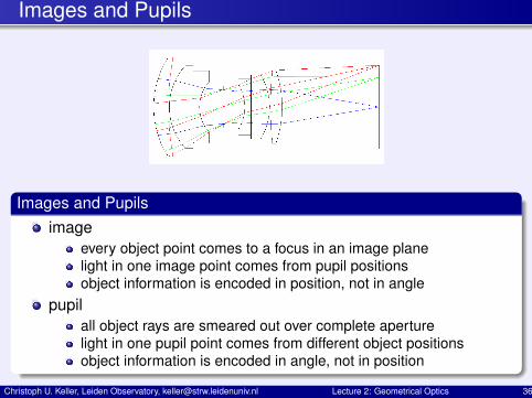
Images and Pupilsimage
every object point comes to a focus in an image planelight in one image point comes from pupil positionsobject information is encoded in position, not in angle
pupilall object rays are smeared out over complete aperturelight in one pupil point comes from different object positionsobject information is encoded in angle, not in position
Christoph U. Keller, Leiden Observatory, [email protected] Lecture 2: Geometrical Optics 36
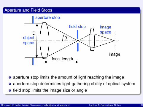
Aperture and Field Stops
aperture stop limits the amount of light reaching the imageaperture stop determines light-gathering ability of optical systemfield stop limits the image size or angle
Christoph U. Keller, Leiden Observatory, [email protected] Lecture 2: Geometrical Optics 37
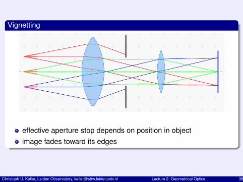
Vignetting
effective aperture stop depends on position in objectimage fades toward its edges
Christoph U. Keller, Leiden Observatory, [email protected] Lecture 2: Geometrical Optics 38
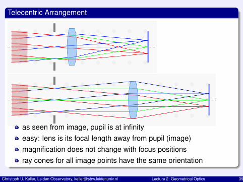
Telecentric Arrangement
as seen from image, pupil is at infinityeasy: lens is its focal length away from pupil (image)magnification does not change with focus positionsray cones for all image points have the same orientation
Christoph U. Keller, Leiden Observatory, [email protected] Lecture 2: Geometrical Optics 39
Aberrations
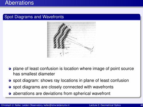
Spot Diagrams and Wavefronts
plane of least confusion is location where image of point sourcehas smallest diameterspot diagram: shows ray locations in plane of least confusionspot diagrams are closely connected with wavefrontsaberrations are deviations from spherical wavefront
Christoph U. Keller, Leiden Observatory, [email protected] Lecture 2: Geometrical Optics 40
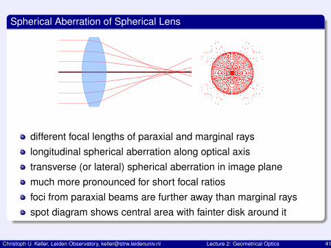
Spherical Aberration of Spherical Lens
Made with Touch Optical Design
different focal lengths of paraxial and marginal rayslongitudinal spherical aberration along optical axistransverse (or lateral) spherical aberration in image planemuch more pronounced for short focal ratiosfoci from paraxial beams are further away than marginal raysspot diagram shows central area with fainter disk around it
Christoph U. Keller, Leiden Observatory, [email protected] Lecture 2: Geometrical Optics 41
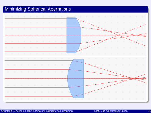
Minimizing Spherical Aberrations
Christoph U. Keller, Leiden Observatory, [email protected] Lecture 2: Geometrical Optics 42
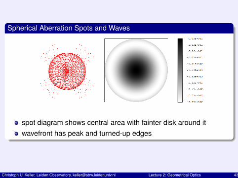
Spherical Aberration Spots and Waves
spot diagram shows central area with fainter disk around itwavefront has peak and turned-up edges
Christoph U. Keller, Leiden Observatory, [email protected] Lecture 2: Geometrical Optics 43
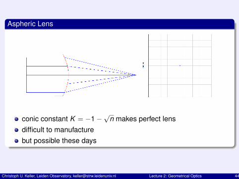
Aspheric Lens
conic constant K = −1−√
n makes perfect lensdifficult to manufacturebut possible these days
Christoph U. Keller, Leiden Observatory, [email protected] Lecture 2: Geometrical Optics 44
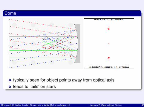
Coma
typically seen for object points away from optical axisleads to ’tails’ on stars
Christoph U. Keller, Leiden Observatory, [email protected] Lecture 2: Geometrical Optics 46
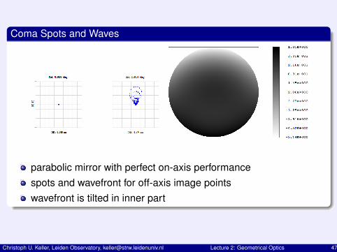
Coma Spots and Waves
parabolic mirror with perfect on-axis performancespots and wavefront for off-axis image pointswavefront is tilted in inner part
Christoph U. Keller, Leiden Observatory, [email protected] Lecture 2: Geometrical Optics 47
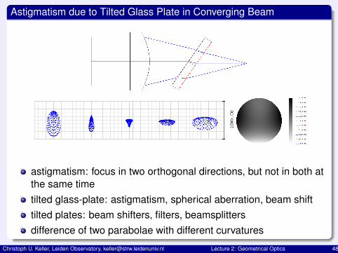
Astigmatism due to Tilted Glass Plate in Converging Beam
astigmatism: focus in two orthogonal directions, but not in both atthe same timetilted glass-plate: astigmatism, spherical aberration, beam shifttilted plates: beam shifters, filters, beamsplittersdifference of two parabolae with different curvatures
Christoph U. Keller, Leiden Observatory, [email protected] Lecture 2: Geometrical Optics 48
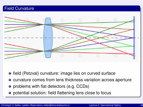
Field Curvature
field (Petzval) curvature: image lies on curved surfacecurvature comes from lens thickness variation across apertureproblems with flat detectors (e.g. CCDs)potential solution: field flattening lens close to focus
Christoph U. Keller, Leiden Observatory, [email protected] Lecture 2: Geometrical Optics 49
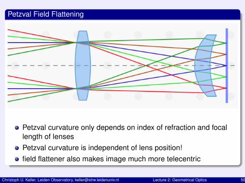
Petzval Field Flattening
Petzval curvature only depends on index of refraction and focallength of lensesPetzval curvature is independent of lens position!field flattener also makes image much more telecentric
Christoph U. Keller, Leiden Observatory, [email protected] Lecture 2: Geometrical Optics 50
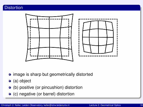
Distortion
image is sharp but geometrically distorted(a) object(b) positive (or pincushion) distortion(c) negative (or barrel) distortion
Christoph U. Keller, Leiden Observatory, [email protected] Lecture 2: Geometrical Optics 51
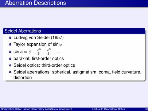
Aberration Descriptions
Seidel AberrationsLudwig von Seidel (1857)Taylor expansion of sinφ
sinφ = φ− φ3
3! +φ5
5! − ...paraxial: first-order opticsSeidel optics: third-order opticsSeidel aberrations: spherical, astigmatism, coma, field curvature,distortion
Christoph U. Keller, Leiden Observatory, [email protected] Lecture 2: Geometrical Optics 52
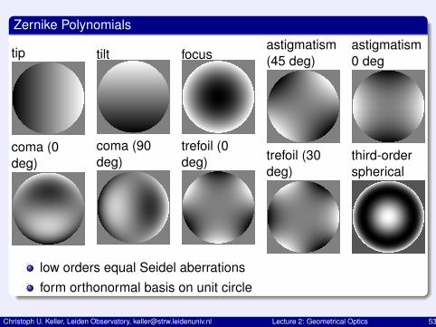
Zernike Polynomials
tip
coma (0deg)
tilt
coma (90deg)
focus
trefoil (0deg)
astigmatism(45 deg)
trefoil (30deg)
astigmatism0 deg
third-orderspherical
low orders equal Seidel aberrationsform orthonormal basis on unit circle
Christoph U. Keller, Leiden Observatory, [email protected] Lecture 2: Geometrical Optics 53