Embed Size (px)
DESCRIPTION
Rapid prototyping
Citation preview
DEMO : Purchase from www.A-PDF.com to remove the watermarkDEMO : Purchase from www.A-PDF.com to remove the watermark
E1C33 11/09/2009 17:30:13 Page 786
Part IX Special Processingand AssemblyTechnologies
33RAPID PROTOTYPING
Chapter Contents
33.1 Fundamentals of Rapid Prototyping
33.2 Rapid Prototyping Technologies33.2.1 Liquid-Based Rapid Prototyping
Systems33.2.2 Solid-Based Rapid Prototyping
Systems33.2.3 Powder-Based Rapid Prototyping
Systems
33.3 Application Issues in Rapid Prototyping
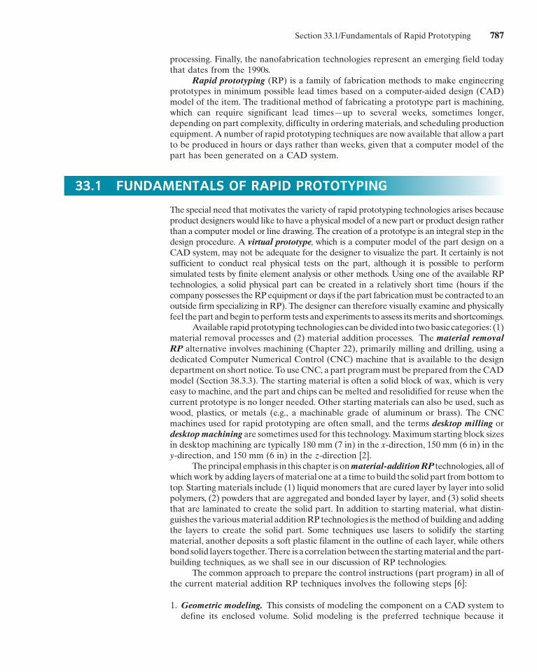
In this part of the book, we discuss a collection of process-ing and assembly technologies that do not fit neatly into ourclassification scheme in Figure 1.4. They are technologiesthat have been adapted from the conventional manufactur-ing and assembly operations or developed from scratch toserve the special functions or needs of designers andmanufacturers. Rapid prototyping, covered in the presentchapter, is a collection of processes used to fabricate amodel, part, or tool in minimum possible time. Chapters 34and 35 discuss technologies used in electronics manufactur-ing, an activity of significant economic importance. Chap-ter 34 covers integrated circuit processing, and Chapter 35covers electronics assembly and packaging. Chapters 36and 37 survey some of the technologies used to producevery small parts and products. Chapter 36 describes micro-fabrication technologies used to produce itemsmeasured inmicrons (10�6 m), whereas Chapter 37 discusses nano-fabrication technologies for producing items measured innanometers (10�9 m). The processes covered in these fivechapters are relatively new. Rapid prototyping dates fromabout 1988. Modern electronics production techniquesdate from around 1960 (Historical Note 34.1), althoughdramatic advances have been made in electronics process-ing since that time. The microfabrication technologiesdiscussed in Chapter 36 followed soon after electronics
786
E1C33 11/09/2009 17:30:13 Page 787
processing. Finally, the nanofabrication technologies represent an emerging field todaythat dates from the 1990s.
Rapid prototyping (RP) is a family of fabrication methods to make engineeringprototypes in minimum possible lead times based on a computer-aided design (CAD)model of the item. The traditional method of fabricating a prototype part is machining,which can require significant lead times—up to several weeks, sometimes longer,depending on part complexity, difficulty in ordering materials, and scheduling productionequipment. A number of rapid prototyping techniques are now available that allow a partto be produced in hours or days rather than weeks, given that a computer model of thepart has been generated on a CAD system.
33.1 FUNDAMENTALS OF RAPID PROTOTYPING
The special need that motivates the variety of rapid prototyping technologies arises becauseproduct designers would like to have a physical model of a new part or product design ratherthan a computer model or line drawing. The creation of a prototype is an integral step in thedesign procedure. A virtual prototype, which is a computer model of the part design on aCAD system, may not be adequate for the designer to visualize the part. It certainly is notsufficient to conduct real physical tests on the part, although it is possible to performsimulated tests by finite element analysis or other methods. Using one of the available RPtechnologies, a solid physical part can be created in a relatively short time (hours if thecompanypossesses theRPequipment or days if the part fabricationmust be contracted to anoutside firm specializing in RP). The designer can therefore visually examine and physicallyfeel thepart andbegin toperform tests andexperiments to assess itsmerits and shortcomings.
Available rapidprototyping technologies canbedivided into twobasic categories: (1)material removal processes and (2) material addition processes. The material removalRP alternative involves machining (Chapter 22), primarily milling and drilling, using adedicated Computer Numerical Control (CNC) machine that is available to the designdepartment on short notice. To use CNC, a part programmust be prepared from theCADmodel (Section 38.3.3). The starting material is often a solid block of wax, which is veryeasy to machine, and the part and chips can be melted and resolidified for reuse when thecurrent prototype is no longer needed. Other starting materials can also be used, such aswood, plastics, or metals (e.g., a machinable grade of aluminum or brass). The CNCmachines used for rapid prototyping are often small, and the terms desktop milling ordesktopmachining are sometimes used for this technology.Maximum starting block sizesin desktop machining are typically 180 mm (7 in) in the x-direction, 150 mm (6 in) in they-direction, and 150 mm (6 in) in the z-direction [2].
Theprincipal emphasis in this chapter is onmaterial-additionRP technologies, all ofwhichwork by adding layers ofmaterial one at a time to build the solid part frombottom totop. Starting materials include (1) liquid monomers that are cured layer by layer into solidpolymers, (2) powders that are aggregated and bonded layer by layer, and (3) solid sheetsthat are laminated to create the solid part. In addition to starting material, what distin-guishes the variousmaterial additionRP technologies is themethod of building and addingthe layers to create the solid part. Some techniques use lasers to solidify the startingmaterial, another deposits a soft plastic filament in the outline of each layer, while othersbond solid layers together.There is a correlationbetween the startingmaterial and thepart-building techniques, as we shall see in our discussion of RP technologies.
The common approach to prepare the control instructions (part program) in all ofthe current material addition RP techniques involves the following steps [6]:
1. Geometric modeling. This consists of modeling the component on a CAD system todefine its enclosed volume. Solid modeling is the preferred technique because it
Section 33.1/Fundamentals of Rapid Prototyping 787
E1C33 11/09/2009 17:30:13 Page 788
provides a complete and unambiguous mathematical representation of the geome-try. For rapid prototyping, the important issue is to distinguish the interior (mass) ofthe part from its exterior, and solid modeling provides for this distinction.
2. Tessellation of the geometric model1. In this step, the CADmodel is converted into aformat that approximates its surfaces by triangles or polygons, with their verticesarranged to distinguish the object’s interior from its exterior. The common tessellationformat used in rapid prototyping is STL, which has become the de facto standard inputformat for nearly all RP systems.
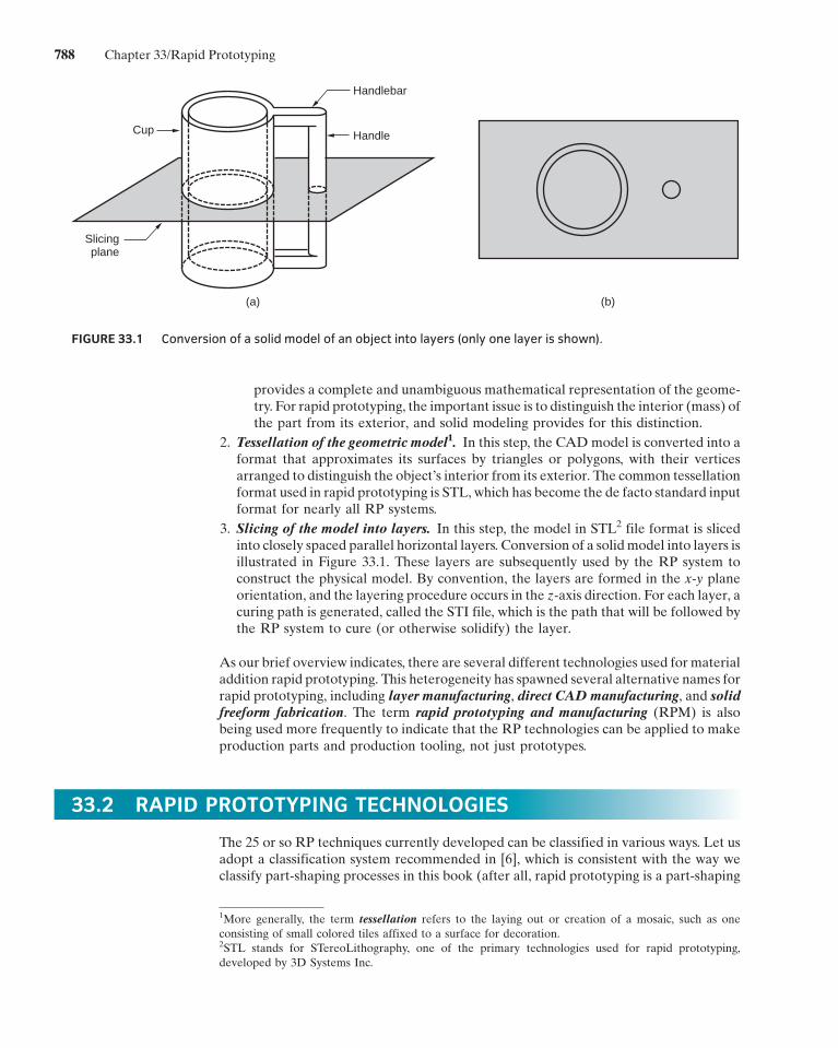
3. Slicing of the model into layers. In this step, the model in STL2 file format is slicedinto closely spaced parallel horizontal layers. Conversion of a solidmodel into layers isillustrated in Figure 33.1. These layers are subsequently used by the RP system toconstruct the physical model. By convention, the layers are formed in the x-y planeorientation, and the layering procedure occurs in the z-axis direction. For each layer, acuring path is generated, called the STI file, which is the path that will be followed bythe RP system to cure (or otherwise solidify) the layer.
As our brief overview indicates, there are several different technologies used for materialaddition rapid prototyping. This heterogeneity has spawned several alternative names forrapid prototyping, including layer manufacturing, direct CADmanufacturing, and solidfreeform fabrication. The term rapid prototyping and manufacturing (RPM) is alsobeing used more frequently to indicate that the RP technologies can be applied to makeproduction parts and production tooling, not just prototypes.
33.2 RAPID PROTOTYPING TECHNOLOGIES
The 25 or so RP techniques currently developed can be classified in various ways. Let usadopt a classification system recommended in [6], which is consistent with the way weclassify part-shaping processes in this book (after all, rapid prototyping is a part-shaping
HandleCup
Slicingplane
Handlebar
(a) (b)
FIGURE 33.1 Conversion of a solid model of an object into layers (only one layer is shown).
1More generally, the term tessellation refers to the laying out or creation of a mosaic, such as oneconsisting of small colored tiles affixed to a surface for decoration.2STL stands for STereoLithography, one of the primary technologies used for rapid prototyping,developed by 3D Systems Inc.
788 Chapter 33/Rapid Prototyping
E1C33 11/09/2009 17:30:14 Page 789
process). The classificationmethod is based on the form of the starting material in the RPprocess: (1) liquid-based, (2) solid-based, and (3) powder-based. We discuss examples ofeach class in the following three sections.
33.2.1 LIQUID-BASED RAPID PROTOTYPING SYSTEMS
The starting material in these technologies is a liquid. About a dozenRP technologies arein this category, of which we have selected the following to describe: (1) stereolithog-raphy, (2) solid ground curing, and (3) droplet deposition manufacturing.
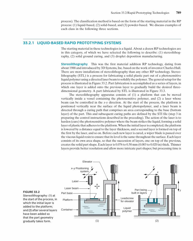
Stereolithography This was the first material addition RP technology, dating fromabout 1988 and introduced by 3DSystems, Inc. basedon theworkof inventorCharlesHull.There are more installations of stereolithography than any other RP technology. Stereo-lithography (STL) is a process for fabricating a solid plastic part out of a photosensitiveliquidpolymerusing adirected laserbeamto solidify thepolymer.Thegeneral setup for theprocess is illustrated in Figure 33.2. Part fabrication is accomplished as a series of layers, inwhich one layer is added onto the previous layer to gradually build the desired three-dimensional geometry. A part fabricated by STL is illustrated in Figure 33.3.
The stereolithography apparatus consists of (1) a platform that can be movedvertically inside a vessel containing the photosensitive polymer, and (2) a laser whosebeam can be controlled in the x-y direction. At the start of the process, the platform ispositioned vertically near the surface of the liquid photopolymer, and a laser beam isdirected through a curing path that comprises an area corresponding to the base (bottomlayer) of the part. This and subsequent curing paths are defined by the STI file (step 3 inpreparing the control instructions described in the preceding). The action of the laser is toharden (cure) the photosensitive polymerwhere the beam strikes the liquid, forming a solidlayerofplastic that adheres to theplatform.Whenthe initial layer is completed, theplatformis lowered by a distance equal to the layer thickness, and a second layer is formed on top ofthe first by the laser, and so on. Before each new layer is cured, a wiper blade is passed overthe viscous liquid resin to ensure that its level is the same throughout the surface. Each layerconsists of its own area shape, so that the succession of layers, one on top of the previous,creates the solid part shape. Each layer is 0.076 to 0.50mm (0.003 to 0.020 in) thick. Thinnerlayers provide better resolution and allowmore intricate part shapes; but processing time is
FIGURE 33.2Stereolithography: (1) at
the start of the process, inwhich the initial layer isadded to the platform;
and (2) after several layershave been added sothat the part geometry
gradually takes form.
Elevator
y y
x xx–y Positioning
system
Laser
Laser beam
Part base
Platform
Container
(1) (2)
z z
Leadscrewfor elevator
Part beingbuilt in layers
Liquidpolymer
Section 33.2/Rapid Prototyping Technologies 789
E1C33 11/09/2009 17:30:14 Page 790
greater. Photopolymers are typically acrylic [13], although use of epoxy for STL has alsobeen reported [10]. The startingmaterials are liquidmonomers. Polymerizationoccurs uponexposure to ultraviolet light produced by helium-cadmium or argon ion lasers. Scan speedsof STL lasers typically range between 500 and 2500 mm/s.
The time required tobuild thepart by this layeringprocess ranges from1hour for smallparts of simple geometry up to several dozen hours for complex parts. Other factors thataffect cycle time are scan speed and layer thickness. The part build time in stereolithographycanbeestimatedbydetermining the time to complete each layer and then summing the timesfor all layers. First, the time to complete a single layer is given by the following equation:
Ti ¼ Ai
vDþ Tr ð33:1Þ
where Ti ¼ time to complete layer i, seconds, where the subscript i is used to identify thelayer;Ai ¼ area of layer i, mm2 (in2); v¼ average scanning speed of the laser beam at thesurface, mm/s (in/sec); D ¼ diameter of the laser beam at the surface (called the ‘‘spotsize,’’ assumed circular), mm (in); and Tr ¼ repositioning time between layers, s.
In the case of stereolithography, the repositioning time involves lowering theworktable in preparation for the next layer to be fabricated. Other RP techniques requireanalogous repositioning steps between layers. The average scanning speed vmust includeany effects of interruptions in the scanning path (e.g., because of gaps between areas ofthe part in a given layer). Once the Ti values have been determined for all layers, then thebuild cycle time can be determined:
Tc ¼Xnl
i¼1
Ti ð33:2Þ
whereTc¼ the STL build cycle time, s; and nl¼ the number of layers used to approximatethe part.3
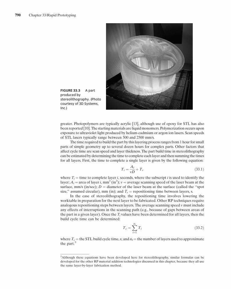
FIGURE 33.3 A partproduced by
stereolithography. (Photocourtesy of 3D Systems,Inc.)
3Although these equations have been developed here for stereolithography, similar formulas can bedeveloped for the other RP material addition technologies discussed in this chapter, because they all usethe same layer-by-layer fabrication method.
790 Chapter 33/Rapid Prototyping
E1C33 11/09/2009 17:30:14 Page 791
After all of the layers have been formed, the photopolymer is about 95% cured.The piece is therefore ‘‘baked’’ in a fluorescent oven to completely solidify the polymer.Excess polymer is removed with alcohol, and light sanding is sometimes used to improvesmoothness and appearance.
Depending on its design and orientation, a part may contain overhanging featuresthat have no means of support during the bottom-up approach used in stereolithography.For example, in the part of Figure 33.1, if the lower half of the handle and the lowerhandlebar were eliminated, the upper portion of the handle would be unsupported duringfabrication. In these cases, extra pillars orwebsmay need to be added to the part simply forsupport purposes.Otherwise, theoverhangsmay float awayorotherwise distort the desiredpart geometry. These extra features must be trimmed away after the process is completed.
Solid Ground Curing Like stereolithography, solid ground curing (SGC)works by curinga photosensitive polymer layer by layer to create a solid model based on CAD geometricdata. Instead of using a scanning laser beam to accomplish the curing of a given layer, theentire layer is exposed to an ultraviolet light source through a mask that is positionedabove the surface of the liquid polymer. The hardening process takes 2 to 3 seconds foreach layer. SGC systems are sold under the name Solider system by Cubital Ltd.
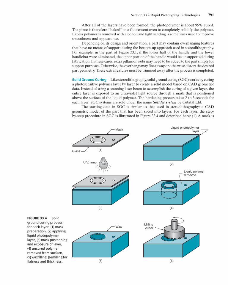
The starting data in SGC is similar to that used in stereolithography: a CADgeometric model of the part that has been sliced into layers. For each layer, the step-by-step procedure in SGC is illustrated in Figure 33.4 and described here: (1) A mask is
FIGURE 33.4 Solidground curing process
for each layer: (1) maskpreparation, (2) applyingliquid photopolymer
layer, (3) mask positioningand exposure of layer,(4) uncured polymerremoved from surface,
(5)waxfilling, (6)millingforflatness and thickness.
U.V. lamp
(1)
(2)
(4)
(6)
(3)
(5)
Mask
WaxMillingcutter
Liquid polymerremoved
Liquid photopolymerlayer
Glass
Section 33.2/Rapid Prototyping Technologies 791
E1C33 11/09/2009 17:30:14 Page 792
created on a glass plate by electrostatically charging a negative image of the layer onto thesurface. The imaging technology is basically the same as that used in photocopiers. (2) Athin flat layer of liquid photopolymer is distributed over the surface of the work platform.(3) The mask is positioned above the liquid polymer surface and exposed by a high-powered (e.g., 2000W) ultraviolet lamp. The portions of the liquid polymer layer that areunprotected by the mask are solidified in about 2 seconds. The shaded areas of the layerremain in the liquid state. (4) The mask is removed, the glass plate is cleaned and madeready for a subsequent layer in step 1. Meanwhile, the liquid polymer remaining on thesurface is removed in a wiping and vacuuming procedure. (5) The now-open areas of thelayer are filled in with hot wax. When hardened, the wax acts to support overhangingsections of thepart. (6)When thewaxhas cooled and solidified, thepolymer-wax surface ismilled to form a flat layer of specified thickness, ready to receive the next application ofliquid photopolymer in step 2. Although we have described SGC as a sequential process,certain steps are accomplished in parallel. Specifically, themask preparation step 1 for thenext layer is performed simultaneously with the layer fabrication steps 2 through 6, usingtwo glass plates during alternating layers.
The sequence for each layer takes about 90 seconds. Throughput time to produce apart by SGC is claimed to be about eight times faster than competing RP systems [6]. Thesolid cubic formcreated inSGCconsistsof solidpolymerandwax.Thewaxprovides supportfor fragile and overhanging features of the part during fabrication, but can be melted awaylater to leave the free-standing part. No post curing of the completed prototype model isrequired, as in stereolithography.
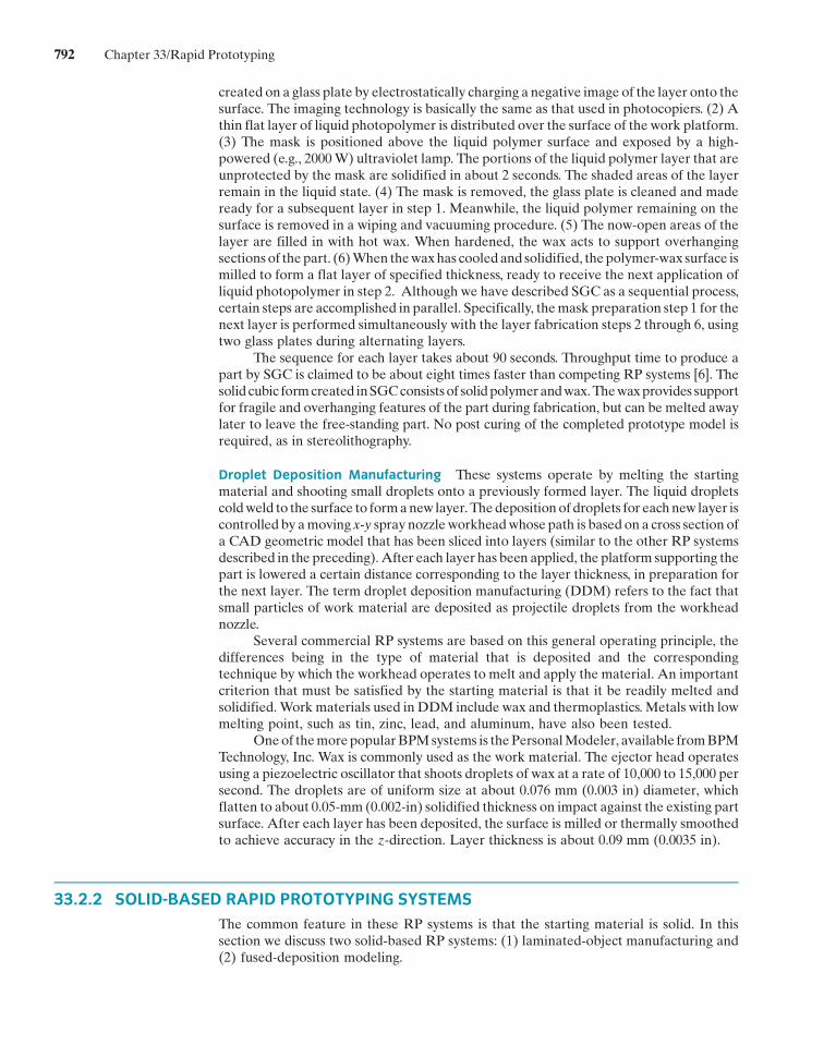
Droplet Deposition Manufacturing These systems operate by melting the startingmaterial and shooting small droplets onto a previously formed layer. The liquid dropletscoldweld to the surface to formanew layer. Thedeposition of droplets for each new layer iscontrolled by amoving x-y spray nozzleworkheadwhose path is based on a cross section ofa CAD geometric model that has been sliced into layers (similar to the other RP systemsdescribed in the preceding).After each layer has been applied, the platform supporting thepart is lowered a certain distance corresponding to the layer thickness, in preparation forthe next layer. The term droplet deposition manufacturing (DDM) refers to the fact thatsmall particles of work material are deposited as projectile droplets from the workheadnozzle.
Several commercial RP systems are based on this general operating principle, thedifferences being in the type of material that is deposited and the correspondingtechnique by which the workhead operates to melt and apply the material. An importantcriterion that must be satisfied by the starting material is that it be readily melted andsolidified.Workmaterials used in DDM include wax and thermoplastics. Metals with lowmelting point, such as tin, zinc, lead, and aluminum, have also been tested.
Oneof themorepopularBPMsystems is thePersonalModeler, available fromBPMTechnology, Inc. Wax is commonly used as the work material. The ejector head operatesusing a piezoelectric oscillator that shoots droplets of wax at a rate of 10,000 to 15,000 persecond. The droplets are of uniform size at about 0.076 mm (0.003 in) diameter, whichflatten to about 0.05-mm (0.002-in) solidified thickness on impact against the existing partsurface. After each layer has been deposited, the surface is milled or thermally smoothedto achieve accuracy in the z-direction. Layer thickness is about 0.09 mm (0.0035 in).
33.2.2 SOLID-BASED RAPID PROTOTYPING SYSTEMS
The common feature in these RP systems is that the starting material is solid. In thissection we discuss two solid-based RP systems: (1) laminated-object manufacturing and(2) fused-deposition modeling.
792 Chapter 33/Rapid Prototyping
E1C33 11/09/2009 17:30:14 Page 793
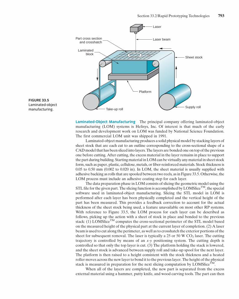
Laminated-Object Manufacturing The principal company offering laminated-objectmanufacturing (LOM) systems is Helisys, Inc. Of interest is that much of the earlyresearch and development work on LOM was funded by National Science Foundation.The first commercial LOM unit was shipped in 1991.
Laminated-objectmanufacturing produces a solid physicalmodel by stacking layers ofsheet stock that are each cut to an outline corresponding to the cross-sectional shape of aCADmodel that has been sliced into layers. The layers are bondedoneon topof thepreviousone before cutting. After cutting, the excess material in the layer remains in place to supportthepart duringbuilding. Startingmaterial inLOMcanbevirtuallyanymaterial in sheet stockform, such as paper, plastic, cellulose,metals, or fiber-reinforcedmaterials. Stock thickness is0.05 to 0.50 mm (0.002 to 0.020 in). In LOM, the sheet material is usually supplied withadhesive backing as rolls that are spooled between two reels, as in Figure 33.5.Otherwise, theLOM process must include an adhesive coating step for each layer.
The data preparation phase in LOMconsists of slicing the geometricmodel using theSTL file for the givenpart. The slicing function is accomplishedbyLOMSliceTM, the specialsoftware used in laminated-object manufacturing. Slicing the STL model in LOM isperformed after each layer has been physically completed and the vertical height of thepart has been measured. This provides a feedback correction to account for the actualthickness of the sheet stock being used, a feature unavailable on most other RP systems.With reference to Figure 33.5, the LOM process for each layer can be described asfollows, picking up the action with a sheet of stock in place and bonded to the previousstack: (1) LOMSliceTM computes the cross-sectional perimeter of the STL model basedon the measured height of the physical part at the current layer of completion. (2) A laserbeam is used to cut along the perimeter, aswell as to crosshatch the exterior portions of thesheet for subsequent removal. The laser is typically a 25 or 50 W CO2 laser. The cuttingtrajectory is controlled by means of an x-y positioning system. The cutting depth iscontrolled so that only the top layer is cut. (3) The platform holding the stack is lowered,and the sheet stock is advanced between supply roll and take-up spool for the next layer.The platform is then raised to a height consistent with the stock thickness and a heatedrollermoves across the new layer to bond it to the previous layer. The height of the physicalstack is measured in preparation for the next slicing computation by LOMSliceTM.
When all of the layers are completed, the new part is separated from the excessexternal material using a hammer, putty knife, and wood carving tools. The part can then
FIGURE 33.5Laminated-object
manufacturing.
Laser
Laser beam
Sheet stock
Supply roll
Platform
Take-up roll
Laminatedblock
Part cross sectionand crosshatch
Section 33.2/Rapid Prototyping Technologies 793

E1C33 11/09/2009 17:30:14 Page 794
be sanded to smooth and blend the layer edges. A sealing application is recommended,using a urethane, epoxy, or other polymer spray to prevent moisture absorption anddamage. LOM part sizes can be relatively large among RP processes, with work volumesup to 800 mm� 500 mm by 550 mm (32 in� 20 in� 22 in). More common work volumesare 380 mm � 250 mm � 350 mm (15 in � 10 in � 14 in).
Several low-cost systems based on the LOM build method are available. Forexample, the JP System 5, available from Schroff Development Corporation, uses amechanical knife rather than a laser to cut the sheet stock for each layer. This system isintended as a teaching tool and requires manual assembly of the layers.
Fused-Deposition Modeling Fused-deposition modeling (FDM) is an RP process inwhich a filament of wax or polymer is extruded onto the existing part surface from aworkhead to complete each new layer. The workhead is controlled in the x-y plane duringeach layer and then moves up by a distance equal to one layer in the z-direction. Thestarting material is a solid filament with typical diameter ¼ 1.25 mm (0.050 in) fed from aspool into theworkhead that heats thematerial to about 0.5�C(1�F) above itsmeltingpointbefore extruding it onto the part surface. The extrudate is solidified and cold welded to thecooler part surface in about 0.1 second. The part is fabricated from the base up, using alayer-by-layer procedure similar to other RP systems.
FDM was developed by Stratasys Inc., which sold its first machine in 1990. Thestarting data is a CAD geometric model that is processed by Stratasys’s software modulesQuickSlice; and SupportWorkTM. QuickSlice; is used to slice the model into layers, andSupportWorkTM is used to generate any support structures that are required during thebuild process. If supports are needed, a dual extrusion head and a differentmaterial is usedto create the supports. The second material is designed to readily be separated from theprimary modeling material. The slice (layer) thickness can be set anywhere from 0.05 to0.75mm(0.002 to0.030 in).About 400mmof filamentmaterial canbedepositedper secondby the extrusion workhead in widths (called the road width) that can be set between 0.25and 2.5 mm (0.010 to 0.100 in). Starting materials are wax and several polymers, includingABS, polyamide, polyethylene, and polypropylene. Thesematerials are nontoxic, allowingthe FDM machine to be set up in an office environment.
33.2.3 POWDER-BASED RAPID PROTOTYPING SYSTEMS
The common feature of the RP technologies described in this section is that the startingmaterial is powder.4 We discuss two RP systems in this category: (1) selective lasersintering and (2) three-dimensional printing.
Selective Laser Sintering Selective laser sintering (SLS) uses a moving laser beam tosinter heat-fusible powders in areas corresponding to the CADgeometric model one layerat a time to build the solid part.After each layer is completed, a new layer of loose powdersis spread across the surface using a counter-rotating roller. The powders are preheated tojust below their melting point to facilitate bonding and reduce distortion. Layer by layer,the powders are gradually bonded into a solid mass that forms the three-dimensional partgeometry. In areas not sintered by the laser beam, the powders remain loose so they can bepoured out of the completed part.Meanwhile, they serve to support the solid regions of thepart as fabrication proceeds. Layer thickness is 0.075 to 0.50 mm (0.003 to 0.020 in).
SLS was developed at the University of Texas (Austin) as an alternative to stereo-lithography, and SLSmachines are currentlymarketed byDTMCorp. It is amore versatileprocess than stereolithography in terms of possible workmaterials. Currentmaterials used
4The definition, characteristics, and production of powders are described in Chapters 16 and 17.
794 Chapter 33/Rapid Prototyping
E1C33 11/09/2009 17:30:14 Page 795
in selective laser sintering include polyvinylchloride, polycarbonate, polyester, poly-urethane, ABS, nylon, and investment casting wax. These materials are less expensivethan the photosensitive resins used in stereolithography. They are also nontoxic and can besinteredusing lowpower (25 to50W)CO2 lasers.Metal and ceramicpowders arealsobeingused in SLS.
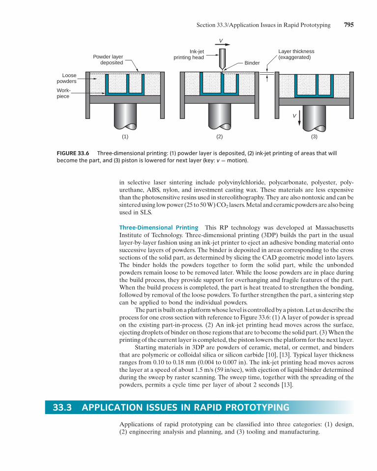
Three-Dimensional Printing This RP technology was developed at MassachusettsInstitute of Technology. Three-dimensional printing (3DP) builds the part in the usuallayer-by-layer fashion using an ink-jet printer to eject an adhesive bonding material ontosuccessive layers of powders. The binder is deposited in areas corresponding to the crosssections of the solid part, as determined by slicing the CAD geometric model into layers.The binder holds the powders together to form the solid part, while the unbondedpowders remain loose to be removed later. While the loose powders are in place duringthe build process, they provide support for overhanging and fragile features of the part.When the build process is completed, the part is heat treated to strengthen the bonding,followed by removal of the loose powders. To further strengthen the part, a sintering stepcan be applied to bond the individual powders.
Thepart is built onaplatformwhose level is controlledbyapiston.Letusdescribe theprocess for one cross section with reference to Figure 33.6: (1) A layer of powder is spreadon the existing part-in-process. (2) An ink-jet printing head moves across the surface,ejecting droplets of binder on those regions that are to become the solid part. (3)When theprinting of the current layer is completed, the piston lowers the platform for the next layer.
Starting materials in 3DP are powders of ceramic, metal, or cermet, and bindersthat are polymeric or colloidal silica or silicon carbide [10], [13]. Typical layer thicknessranges from 0.10 to 0.18 mm (0.004 to 0.007 in). The ink-jet printing head moves acrossthe layer at a speed of about 1.5 m/s (59 in/sec), with ejection of liquid binder determinedduring the sweep by raster scanning. The sweep time, together with the spreading of thepowders, permits a cycle time per layer of about 2 seconds [13].
33.3 APPLICATION ISSUES IN RAPID PROTOTYPING
Applications of rapid prototyping can be classified into three categories: (1) design,(2) engineering analysis and planning, and (3) tooling and manufacturing.
(1) (2) (3)
Powder layerdeposited
Loosepowders
V
V
Ink-jetprinting head
Binder
Layer thickness(exaggerated)
Work-piece
FIGURE 33.6 Three-dimensional printing: (1) powder layer is deposited, (2) ink-jet printing of areas that willbecome the part, and (3) piston is lowered for next layer (key: v ¼motion).
Section 33.3/Application Issues in Rapid Prototyping 795
E1C33 11/09/2009 17:30:14 Page 796
Design Thiswas the initial application area forRP systems.Designers are able to confirmtheir designby building a real physicalmodel inminimumtimeusing rapid prototyping. Thefeatures and functions of the part can be communicated to others more easily using aphysicalmodel than by a paper drawing or displaying it on aCAD systemmonitor. Benefitsto design attributed to rapid prototyping include [2]: (1) reduced lead times to produceprototype components, (2) improved ability to visualize the part geometry because of itsphysical existence, (3) earlier detection and reduction of design errors, and (4) increasedcapability to compute mass properties of components and assemblies.
Engineering Analysis and Planning The existence of an RP-fabricated part allows forcertain types of engineering analysis and planning activities to be accomplished that wouldbemore difficult without the physical entity. Someof the possibilities are (1) comparison ofdifferent shapes and styles to optimize aesthetic appeal of the part; (2) analysis of fluid flowthrough different orifice designs in valves fabricated by RP; (3) wind tunnel testing ofdifferent streamline shapes using physical models created by RP; (4) stress analysis of aphysical model; (5) fabrication of preproduction parts by RP as an aid in process planningand tool design; and (6) combining medical imaging technologies, such as magneticresonance imaging (MRI), with RP to create models for doctors in planning surgicalprocedures or fabricating prostheses or implants.
Tooling andManufacturing The trend inRPapplications is toward its greater use in thefabrication of production tooling and for actual manufacture of parts.WhenRP is adoptedto fabricate production tooling, the term rapid tool making (RTM) is often used. RTMapplications divide into two approaches [4]: indirect RTM method, in which a pattern iscreated by RP and the pattern is used to fabricate the tool, and direct RTM method, inwhichRP isused tomake the tool itself.Examplesof indirectRTMinclude (1) useofanRP-fabricated part as themaster inmaking a silicon rubbermold that is subsequently used as aproduction mold, (2) RP patterns to make the sand molds in sand casting (Section 11.1),(3) fabrication of patterns of low-melting point materials (e.g., wax) in limited quantitiesfor investment casting (Section11.2.4), and (4)makingelectrodes forEDM(Section26.3.1)[6], [10]. Examples of direct RTM include: (1) RP-fabricated mold cavity inserts that canbe sprayed with metal to produce injection molds for a limited quantity of productionplastic parts (Section 13.6) and (2) 3-D printing to create a die geometry in metallicpowders followed by sintering and infiltration to complete the fabrication of the die [4],[6], [10].
Examples of actual part production include [10]: (1) small batch sizes of plasticparts that could not be economically injection molded because of the high cost of themold, (2) parts with intricate internal geometries that could not be made using conven-tional technologies without assembly, and (3) one-of-a-kind parts such as bone replace-ments that must be made to correct size for each user.
Not all RP technologies can be used for all of these tooling and manufacturingexamples. Interested readers should consult more complete treatments of the RPtechnologies for specific details on these and other examples.
Problems with Rapid Prototyping The principal problems with current RP technol-ogies include (1) part accuracy, (2) limited variety of materials, and (3) mechanicalperformance of the fabricated parts.
Several sources of error limit part accuracy in RP systems: (1) mathematical,(2) process related, or (3) material related [13]. Mathematical errors include approxima-tions of part surfaces used in RP data preparation and differences between the slicingthicknesses andactual layer thicknesses in thephysical part. The latter differences result inz-axis dimensional errors. An inherent limitation in the physical part is the steps betweenlayers, especially as layer thickness is increased, resulting in a staircase appearance for
796 Chapter 33/Rapid Prototyping
E1C33 11/09/2009 17:30:14 Page 797
sloping part surfaces. Process-related errors are those that result from the particular partbuilding technologyused in theRP system.These errors degrade the shapeof each layer aswell as the registration between adjacent layers. Process errors can also affect the z-axisdimension. Finally, material-related errors include shrinkage and distortion. An allow-ance for shrinkage canbemadeby enlarging theCADmodel of the part basedonpreviousexperience with the process and materials.
Current rapid prototyping systems are limited in the variety of materials they canprocess. For example, the most common RP technology, stereolithography, is limited tophotosensitive polymers. In general, the materials used in RP systems are not as strong asthe production part materials that will be used in the actual product. This limits themechanical performance of the prototypes and the amount of realistic testing that can bedone to verify the design during product development.
REFERENCES
[1] Ashley, S. ‘‘Rapid Prototyping Is Coming of Age,’’Mechanical Engineering, July 1995, pp. 62–68.
[2] Bakerjian, R., and Mitchell, P. (eds.). Tool and Man-ufacturing Engineers Handbook, 4th ed., Vol. VI,Design for Manufacturability. Society of Manufactur-ing Engineers, Dearborn, Michigan, 1992, Chapter 7.
[3] Destefani, J. ‘‘Plus or Minus,’’ Manufacturing Engi-neering, April 2005, pp. 93–97.
[4] Hilton, P. ‘‘Making the Leap to Rapid ToolMaking,’’Mechanical Engineering, July 1995, pp. 75–76.
[5] Kai, C. C., and Fai, L. K.‘‘Rapid Prototyping andManufacturing: The Essential Link between DesignandManufacturing,’’Chapter 6 in IntegratedProductandProcessDevelopment:Methods,Tools, andTech-nologies, J.M.Usher,U.Roy, andH.R.Parsaei (eds.).John Wiley & Sons, New York, 1998, pp. 151–183.
[6] Kai, C. C., Fai, L. K., and Chu-Sing, L. RapidPrototyping: Principles and Applications. 2nd ed.World Scientific Publishing Co., Singapore, 2003.
[7] Kochan, D., Kai, C. C. and Zhaohui, D. ‘‘RapidPrototyping Issues in the 21st Century,’’ Computersin Industry, Vol. 39, pp. 3–10, 1999.
[8] Noorani, R. I., Rapid Prototyping: Principles andApplications, John Wiley & Sons, Hoboken, NewJersey, 2006.
[9] Pacheco, J. M. Rapid Prototyping, Report MTIACSOAR-93-01. Manufacturing Technology Informa-tion Analysis Center, IIT Research Institute,Chicago, 1993.
[10] Pham, D. T., and Gault, R. S. ‘‘A Comparison ofRapid Prototyping Technologies,’’ InternationalJournal of Machine Tools and Manufacture, Vol.38, pp. 1257–1287, 1998.
[11] Tseng, A. A., Lee, M. H., and Zhao, B. ‘‘Design andOperation of a Droplet Deposition System for Free-form Fabrication of Metal Parts,’’ ASME Journal ofEng. Mat. Tech., Vol. 123, No. 1, 2001.
[12] Wohlers, T., ‘‘Direct Digital Manufacturing,’’Manufacturing Engineering, January 2009,pp. 73–81.
[13] Yan, X., and Gu, P. ‘‘AReview of Rapid PrototypingTechnologies and Systems,’’ Computer-AidedDesign, Vol. 28, No. 4, pp. 307–318, 1996.
REVIEW QUESTIONS
33.1. What is rapid prototyping? Provide a definition ofthe term.
33.2. What are the three types of starting materials inrapid prototyping?
33.3. Besides the starting material, what other featuredistinguishes the rapid prototyping technologies?
33.4. What is the common approach used in all of thematerial addition technologies to prepare the con-trol instructions for the RP system?
33.5. Of all of the current rapid prototyping technolo-gies, which one is the most widely used?
33.6. Describe the RP technology called solid groundcuring.
33.7. Describe the RP technology called laminated-object manufacturing.
33.8. What is the starting material in fused-depositionmodeling?
Review Questions 797