Embed Size (px)
Citation preview
1
(5.1)
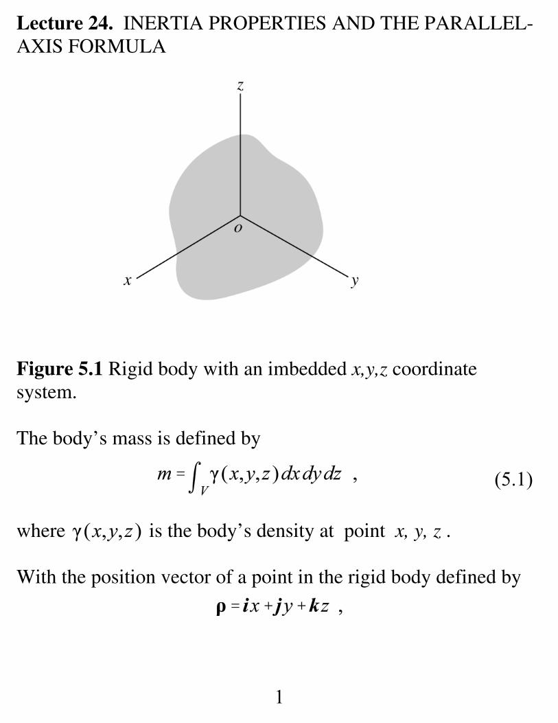
Lecture 24. INERTIA PROPERTIES AND THE PARALLEL-AXIS FORMULA
Figure 5.1 Rigid body with an imbedded x,y,z coordinatesystem.
The body’s mass is defined by
where is the body’s density at point x, y, z .
With the position vector of a point in the rigid body defined by
2
(5.2)
(5.3)
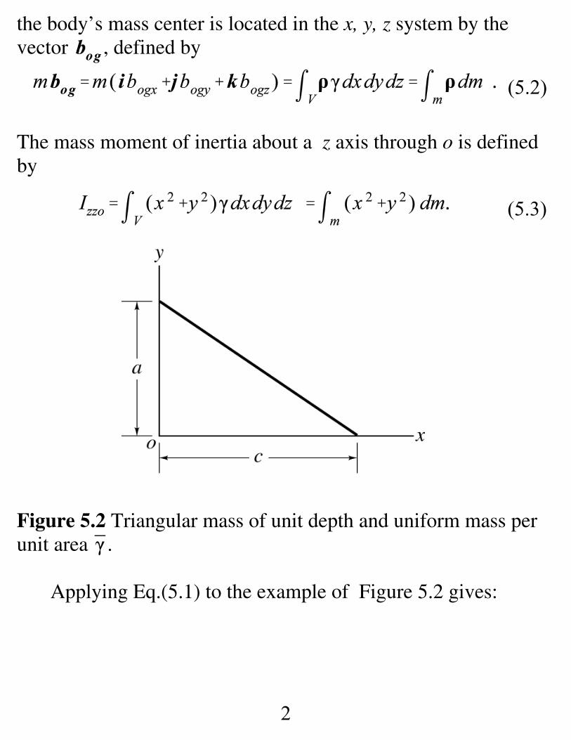
the body’s mass center is located in the x, y, z system by thevector , defined by
The mass moment of inertia about a z axis through o is definedby
Figure 5.2 Triangular mass of unit depth and uniform mass perunit area .
Applying Eq.(5.1) to the example of Figure 5.2 gives:
3
(5.4)
Applying Eq.(5.2) to find the mass center gives
Hence,
and:
The mass center is located in the x, y system by
4
(5.5)
.
Proceeding from Eq.(5.3) for the moment-of-inertia definitionabout o is,
A considerable amount of work is hidden in getting across thelast equality sign.
The radius of gyration is defined as the radius at which all of themass could be concentrated to obtain the correct moment ofinertia. For this example,
A particle has all of its mass concentrated at a point and hasnegligible dimensions of length, breadth, depth, etc. Rigidbodies have finite dimensions, yielding properties such as area,volume, and moment of inertia. Observe that continuing toreduce the dimensions of the triangular plate in figure 5.2 willcause the moment of inertia defined by Eq.(5.5) to rapidlyapproach zero, which is consistent with a particle.
The Parallel-Axis Formula
5
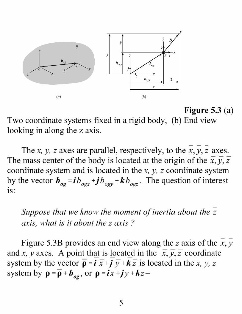
Figure 5.3 (a)Two coordinate systems fixed in a rigid body, (b) End viewlooking in along the z axis.
The x, y, z axes are parallel, respectively, to the axes. The mass center of the body is located at the origin of the coordinate system and is located in the x, y, z coordinate systemby the vector . The question of interestis:
Suppose that we know the moment of inertia about the axis, what is it about the z axis ?
Figure 5.3B provides an end view along the z axis of the and x, y axes. A point that is located in the coordinatesystem by the vector is located in the x, y, zsystem by , or =
6
(5.6)
(5.7)
; hence,
The moment of inertia about the z axis is defined to be
Substituting for x and y gives
Because the mass center is at the origin of the coordinatesystem, the last two integrals in Eq.(5.6) are zero, and we obtain
Note that this expression is only valid when the mass center ofthe body is at the origin of the coordinate system.
7
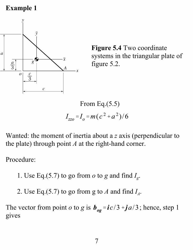
Example 1
Figure 5.4 Two coordinatesystems in the triangular plate offigure 5.2.
From Eq.(5.5)
Wanted: the moment of inertia about a z axis (perpendicular tothe plate) through point A at the right-hand corner.
Procedure:
1. Use Eq.(5.7) to go from o to g and find Ig.
2. Use Eq.(5.7) to go from g to A and find IA.
The vector from point o to g is ; hence, step 1gives
8
The vector from point g to point A is . Hence,step 2 gives
Note
9
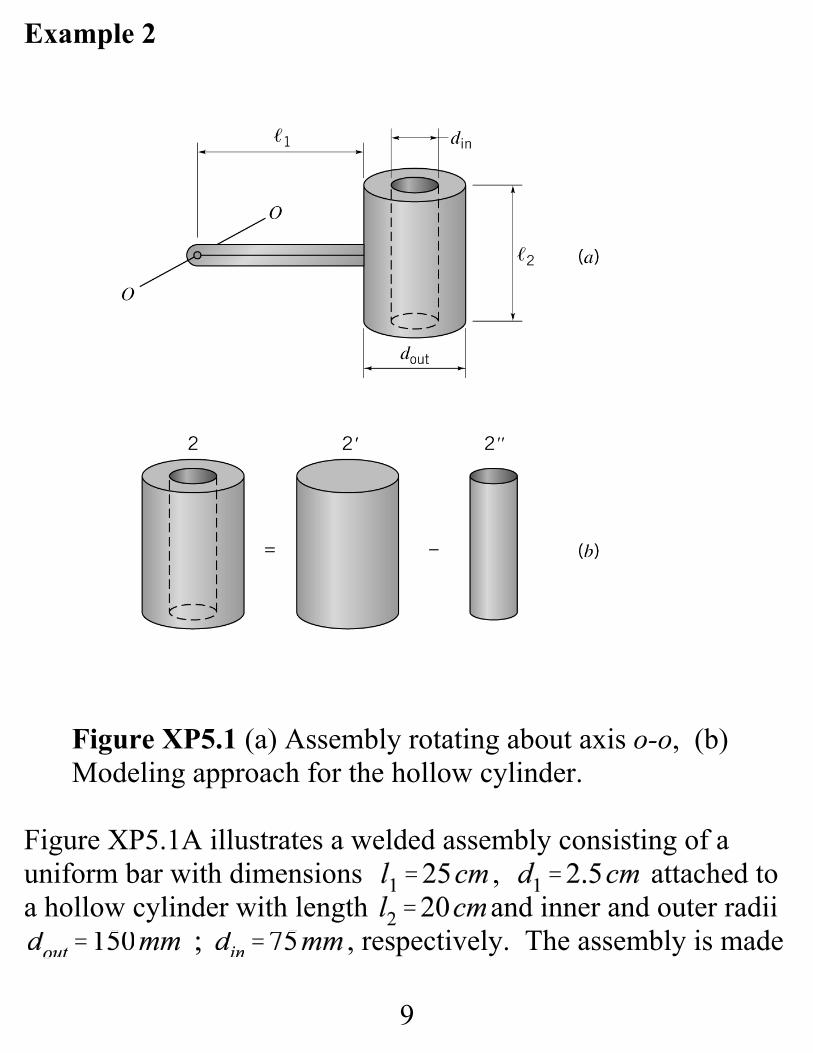
Example 2
Figure XP5.1 (a) Assembly rotating about axis o-o, (b)Modeling approach for the hollow cylinder.
Figure XP5.1A illustrates a welded assembly consisting of auniform bar with dimensions , attached toa hollow cylinder with length and inner and outer radii
, respectively. The assembly is made
10
( i )
from steel with density . The assembly rotatesabout the o-o axis.
The following engineering-analysis tasks apply:
a. Determine the moment of inertia of the assembly aboutthe o-o axis.
b. Determine the assembly’s radius of gyration for rotationabout the o-o axis.
b. Determine the assembly’s mass-center location.
Solution Break the assembly into two pieces and analyze the barand hollow cylinder separately.
Slender Bar: The moment of inertia for a slender bar about atransverse axis at its end is , and the moment ofinertia for a transverse axis through the mass center is
. These results are related to each other via theparallel-axis formula as
You should work at committing the bar’s inertia-propertydefinition to memory. The bar’s mass is
11
(iv)
(vi)
(v)
(ii)
(iii)
Hence, from Eq.( i ),
Hollow Cylinder: figure XP5.1B shows that the hollow cylindercan be “constructed” by subtracting a solid cylinder (denoted )with the inner diameter from a solid cylinder (denoted )with the outer radius . Starting with the inner cylinder
From Appendix C, the moment of inertia for a transverse axisthrough the inner cylinder’s mass center is
For the solid outer cylinder,
12
(viii)
(vii)
and
From Eqs.(iv) through (vii),
These values conclude the individual results for the hollowcylinder.
Combining the results for the bar and the hollow cylinder via theparallel-axis formula, the assembly moment of inertia is
and concludes Task a. The radius of gyration kg is obtainedfrom where m is the assembly moment of inertia; hence,
and concludes Task b.The assembly mass location is found from
13
hence,
Note that the mass center location defined by d is not related tothe radius of gyration kg .
14
Lecture 25. GOVERNING FORCE AND MOMENTEQUATIONS FOR PLANAR MOTION OF A RIGID BODYWITH APPLICATION EXAMPLES
Given: for a particle.
Find: force and moment differential equations of motion forplanar motion of a rigid body.
Force Equation
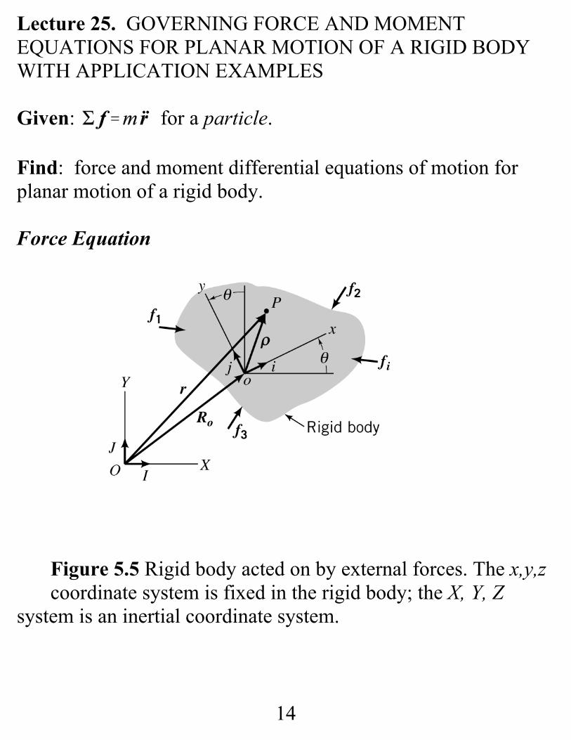
Figure 5.5 Rigid body acted on by external forces. The x,y,z coordinate system is fixed in the rigid body; the X, Y, Z
system is an inertial coordinate system.
15
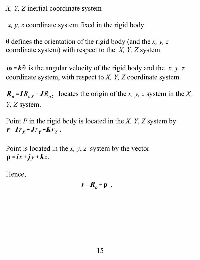
X, Y, Z inertial coordinate system
x, y, z coordinate system fixed in the rigid body.
θ defines the orientation of the rigid body (and the x, y, zcoordinate system) with respect to the X, Y, Z system.
is the angular velocity of the rigid body and the x, y, zcoordinate system, with respect to X, Y, Z coordinate system.
locates the origin of the x, y, z system in the X,Y, Z system.
Point P in the rigid body is located in the X, Y, Z system by .
Point is located in the x, y, z system by the vector
Hence,
16
(5.8)
Force Equation. Applying Newton’s second law to the particleat P gives
where:
fP is the resultant force
is the acceleration of the particle with respect to theinertial X, Y, Z system.
where γ is the mass density of the rigid body.
The resultant force at P is
On the left hand side of Eq.(5.8), integrating over the mass of thebody gives
i.e., when integrated over the whole body, the internal forcescancel.

17
(5.9)
(5.10)
(5.11)
(5.12)
The integral expression of Eq.(5.8) is then
For the two points o and P in the rigid body
Since and locate points P and o, respectively, in the X, Y, Zsystem, and ρ is the vector from point o to P,
Since , integration extends over the volume of therigid body.
Since and ω are constant with respect to the x, y, zintegration variables they can be brought outside the integral signyielding
The mass center is located in the x, y, z system by , definedby

18
(5.13)
Substituting from Eq.(5.12) into Eq.(5.11) gives
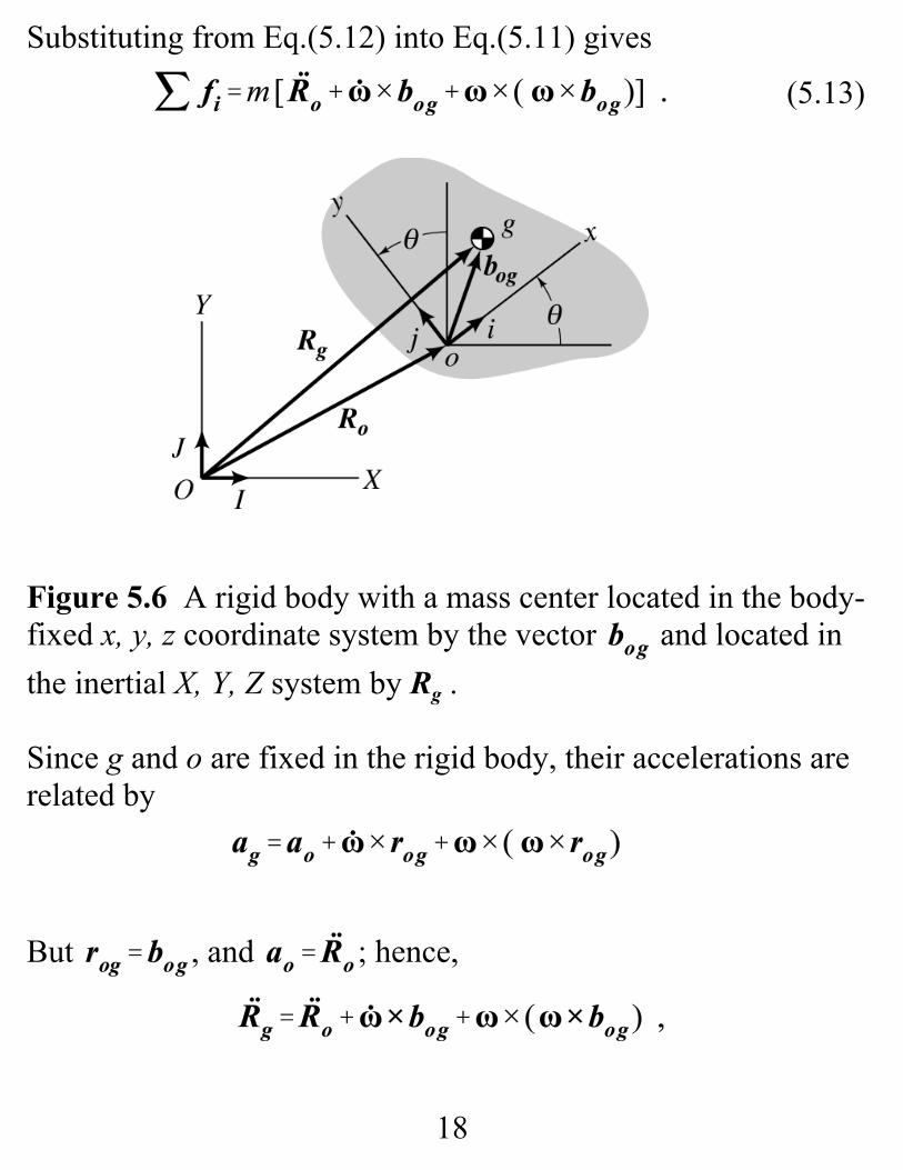
Figure 5.6 A rigid body with a mass center located in the body-fixed x, y, z coordinate system by the vector and located inthe inertial X, Y, Z system by Rg .
Since g and o are fixed in the rigid body, their accelerations arerelated by
But , and ; hence,

19
(5.14)
(5.15a)
(5.15b)
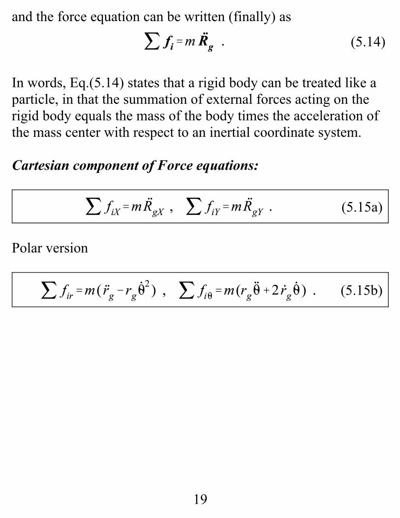
and the force equation can be written (finally) as
In words, Eq.(5.14) states that a rigid body can be treated like aparticle, in that the summation of external forces acting on therigid body equals the mass of the body times the acceleration ofthe mass center with respect to an inertial coordinate system.
Cartesian component of Force equations:
Polar version
20
(5.16)
(5.17)
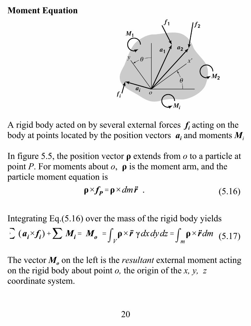
Moment Equation
A rigid body acted on by several external forces fi acting on thebody at points located by the position vectors ai and moments Mi
In figure 5.5, the position vector ρ extends from o to a particle atpoint P. For moments about o, ρ is the moment arm, and theparticle moment equation is
Integrating Eq.(5.16) over the mass of the rigid body yields
The vector Mo on the left is the resultant external moment actingon the rigid body about point o, the origin of the x, y, zcoordinate system.

21
(5.18)
(5.19)
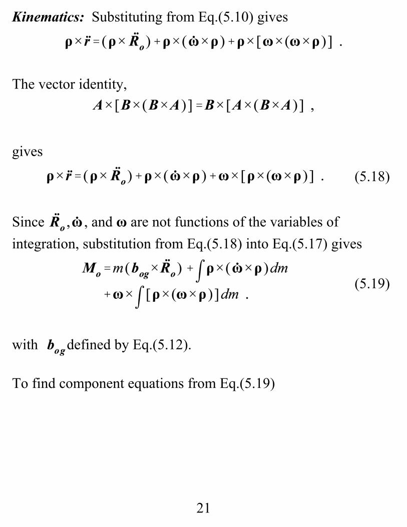
Kinematics: Substituting from Eq.(5.10) gives
The vector identity,
gives
Since , and ω are not functions of the variables ofintegration, substitution from Eq.(5.18) into Eq.(5.17) gives
with defined by Eq.(5.12).
To find component equations from Eq.(5.19)
22
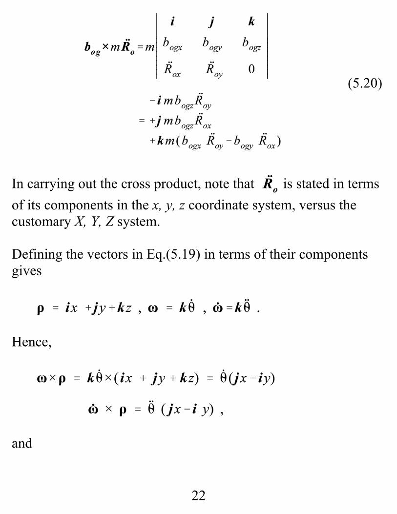
(5.20)
In carrying out the cross product, note that is stated in termsof its components in the x, y, z coordinate system, versus thecustomary X, Y, Z system.
Defining the vectors in Eq.(5.19) in terms of their componentsgives
Hence,
and
23
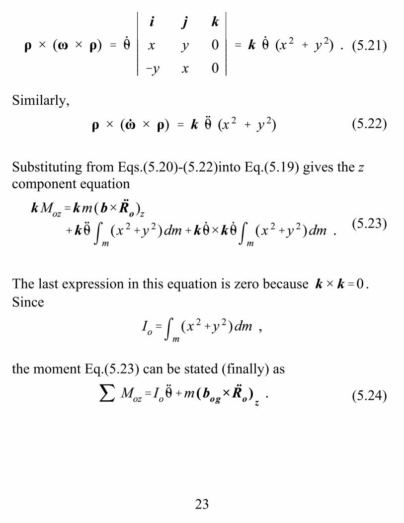
(5.21)
(5.22)
(5.23)
(5.24)
Similarly,
Substituting from Eqs.(5.20)-(5.22)into Eq.(5.19) gives the zcomponent equation
The last expression in this equation is zero because . Since
the moment Eq.(5.23) can be stated (finally) as

24
(5.15)
(5.24)
(5.25)
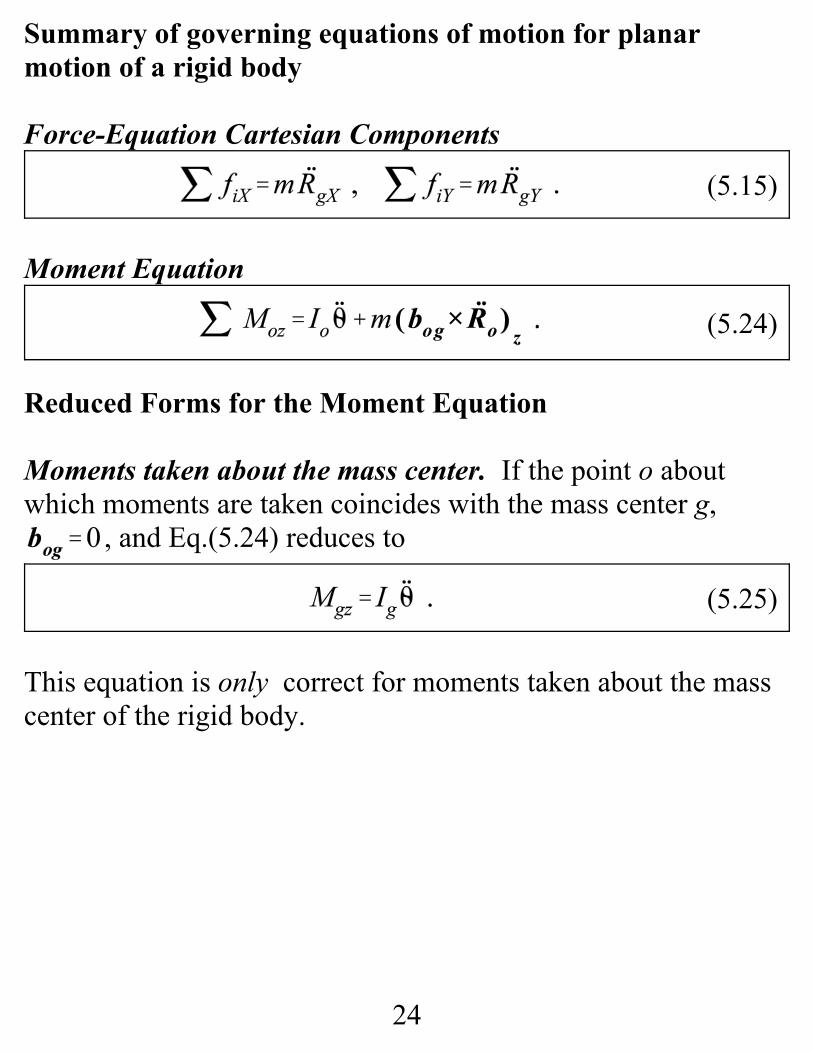
Summary of governing equations of motion for planarmotion of a rigid body
Force-Equation Cartesian Components
Moment Equation
Reduced Forms for the Moment Equation
Moments taken about the mass center. If the point o aboutwhich moments are taken coincides with the mass center g,
, and Eq.(5.24) reduces to
This equation is only correct for moments taken about the masscenter of the rigid body.

25
(5.26)
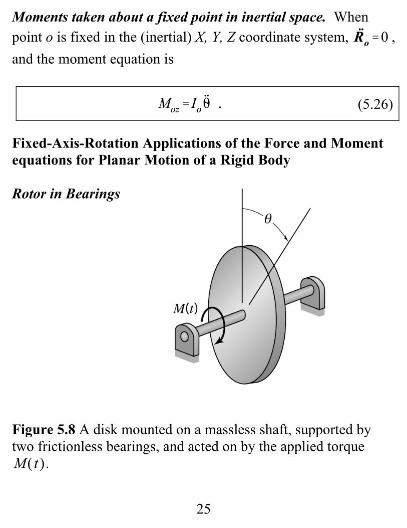
Moments taken about a fixed point in inertial space. Whenpoint o is fixed in the (inertial) X, Y, Z coordinate system, ,and the moment equation is
Fixed-Axis-Rotation Applications of the Force and Momentequations for Planar Motion of a Rigid Body
Rotor in Bearings
Figure 5.8 A disk mounted on a massless shaft, supported bytwo frictionless bearings, and acted on by the applied torque
.
26
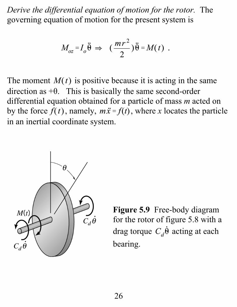
Derive the differential equation of motion for the rotor. Thegoverning equation of motion for the present system is
The moment is positive because it is acting in the samedirection as +θ. This is basically the same second-orderdifferential equation obtained for a particle of mass m acted onby the force , namely, , where x locates the particlein an inertial coordinate system.
Figure 5.9 Free-body diagramfor the rotor of figure 5.8 with a drag torque acting at eachbearing.

27
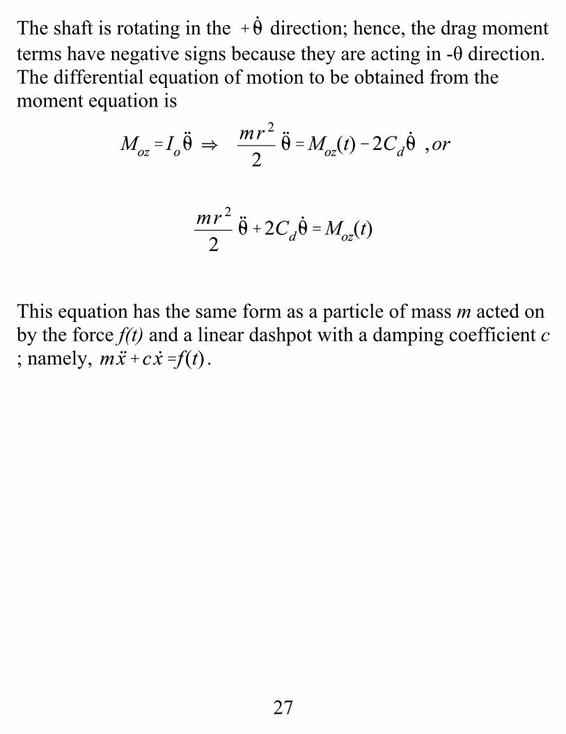
The shaft is rotating in the direction; hence, the drag momentterms have negative signs because they are acting in -θ direction. The differential equation of motion to be obtained from themoment equation is
This equation has the same form as a particle of mass m acted onby the force f(t) and a linear dashpot with a damping coefficient c; namely, .

28
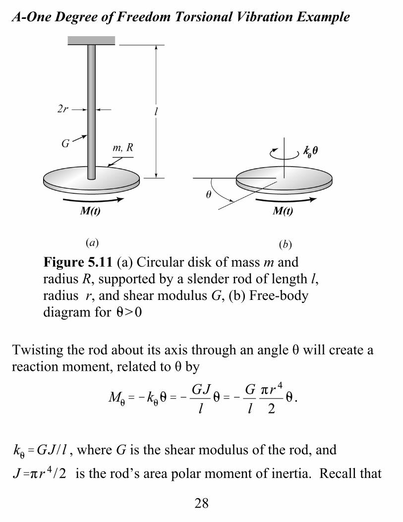
A-One Degree of Freedom Torsional Vibration Example
Twisting the rod about its axis through an angle θ will create areaction moment, related to θ by
, where G is the shear modulus of the rod, and is the rod’s area polar moment of inertia. Recall that
Figure 5.11 (a) Circular disk of mass m andradius R, supported by a slender rod of length l,radius r, and shear modulus G, (b) Free-bodydiagram for
29
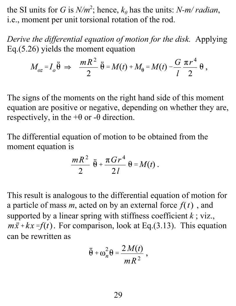
the SI units for G is N/m2; hence, kθ has the units: N-m/ radian,i.e., moment per unit torsional rotation of the rod.
Derive the differential equation of motion for the disk. ApplyingEq.(5.26) yields the moment equation
The signs of the moments on the right hand side of this momentequation are positive or negative, depending on whether they are,respectively, in the +θ or -θ direction.
The differential equation of motion to be obtained from themoment equation is
This result is analogous to the differential equation of motion fora particle of mass m, acted on by an external force , andsupported by a linear spring with stiffness coefficient k ; viz.,
For comparison, look at Eq.(3.13). This equationcan be rewritten as

30
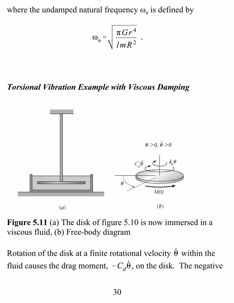
where the undamped natural frequency ωn is defined by
Torsional Vibration Example with Viscous Damping
Figure 5.11 (a) The disk of figure 5.10 is now immersed in aviscous fluid, (b) Free-body diagram
Rotation of the disk at a finite rotational velocity within thefluid causes the drag moment, , on the disk. The negative

31
(5.27)
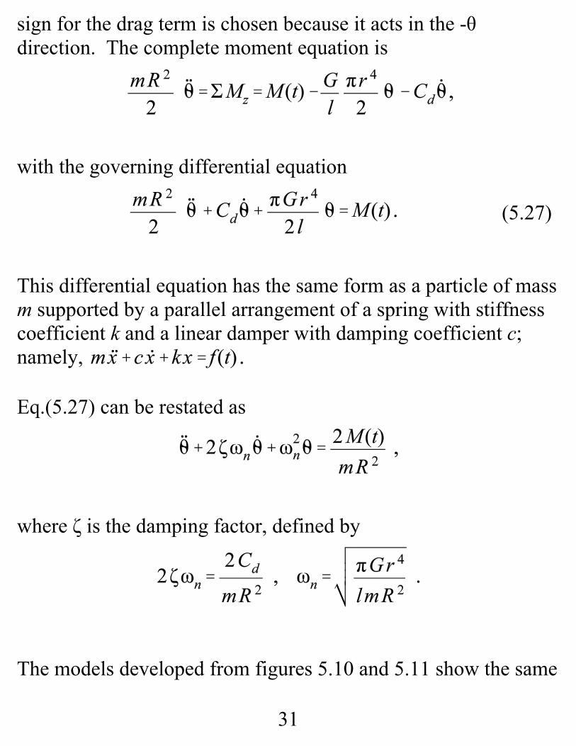
sign for the drag term is chosen because it acts in the -θdirection. The complete moment equation is
with the governing differential equation
This differential equation has the same form as a particle of massm supported by a parallel arrangement of a spring with stiffnesscoefficient k and a linear damper with damping coefficient c;namely,
Eq.(5.27) can be restated as
where ζ is the damping factor, defined by
The models developed from figures 5.10 and 5.11 show the same

32
damped and undamped vibration possibilities for rotationalmotion of a disk that we reviewed earlier for linear motion of aparticle. The same possibilities exist to define damped andundamped natural frequencies, damping factors, etc.
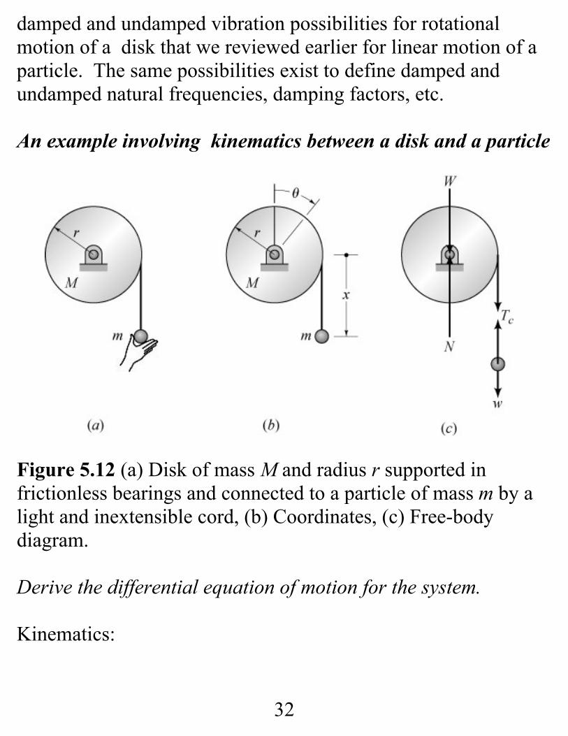
An example involving kinematics between a disk and a particle
Figure 5.12 (a) Disk of mass M and radius r supported infrictionless bearings and connected to a particle of mass m by alight and inextensible cord, (b) Coordinates, (c) Free-bodydiagram.
Derive the differential equation of motion for the system.
Kinematics:

33
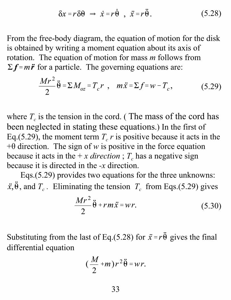
(5.28)
(5.29)
(5.30)
From the free-body diagram, the equation of motion for the diskis obtained by writing a moment equation about its axis ofrotation. The equation of motion for mass m follows from
for a particle. The governing equations are:
where Tc is the tension in the cord. ( The mass of the cord hasbeen neglected in stating these equations.) In the first ofEq.(5.29), the moment term Tc r is positive because it acts in the+θ direction. The sign of w is positive in the force equationbecause it acts in the + x direction ; Tc has a negative signbecause it is directed in the -x direction.
Eqs.(5.29) provides two equations for the three unknowns:, and Tc . Eliminating the tension Tc from Eqs.(5.29) gives
Substituting from the last of Eq.(5.28) for gives the finaldifferential equation

34
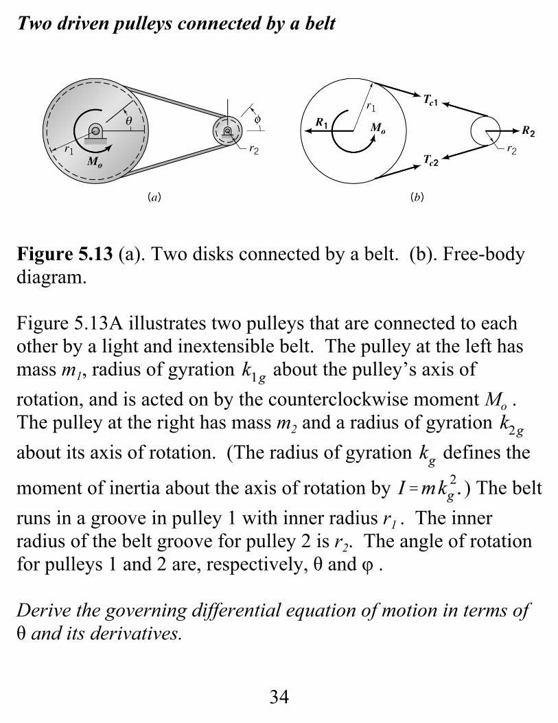
Two driven pulleys connected by a belt
Figure 5.13 (a). Two disks connected by a belt. (b). Free-bodydiagram.
Figure 5.13A illustrates two pulleys that are connected to eachother by a light and inextensible belt. The pulley at the left hasmass m1, radius of gyration about the pulley’s axis ofrotation, and is acted on by the counterclockwise moment Mo . The pulley at the right has mass m2 and a radius of gyration about its axis of rotation. (The radius of gyration defines the
moment of inertia about the axis of rotation by ) The beltruns in a groove in pulley 1 with inner radius r1 . The innerradius of the belt groove for pulley 2 is r2. The angle of rotationfor pulleys 1 and 2 are, respectively, θ and φ .
Derive the governing differential equation of motion in terms ofθ and its derivatives.
35
(5.31)
(5.32)
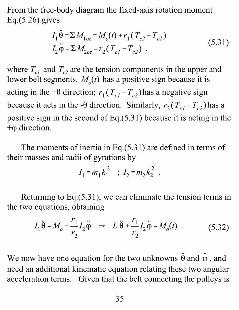
From the free-body diagram the fixed-axis rotation momentEq.(5.26) gives:
where Tc1 and Tc2 are the tension components in the upper andlower belt segments. has a positive sign because it isacting in the +θ direction; has a negative signbecause it acts in the -θ direction. Similarly, has apositive sign in the second of Eq.(5.31) because it is acting in the+φ direction.
The moments of inertia in Eq.(5.31) are defined in terms oftheir masses and radii of gyrations by
Returning to Eq.(5.31), we can eliminate the tension terms inthe two equations, obtaining
We now have one equation for the two unknowns and , andneed an additional kinematic equation relating these two angularacceleration terms. Given that the belt connecting the pulleys is

36
inextensible (can not stretch) the velocity v of the belt leavingboth pulleys must be equal; hence,
Substituting this result back into Eq.(5.32) gives the desired finalresult
Note that coupling the two pulleys’ motion by the belt acts toincrease the effective inertia Ieff in resisting the applied moment.

14
Lecture 25. GOVERNING FORCE AND MOMENTEQUATIONS FOR PLANAR MOTION OF A RIGID BODYWITH APPLICATION EXAMPLES
Given: for a particle.
Find: force and moment differential equations of motion forplanar motion of a rigid body.
Force Equation
Figure 5.5 Rigid body acted on by external forces. The x,y,z coordinate system is fixed in the rigid body; the X, Y, Z
system is an inertial coordinate system.

15
X, Y, Z inertial coordinate system
x, y, z coordinate system fixed in the rigid body.
θ defines the orientation of the rigid body (and the x, y, zcoordinate system) with respect to the X, Y, Z system.
is the angular velocity of the rigid body and the x, y, zcoordinate system, with respect to X, Y, Z coordinate system.
locates the origin of the x, y, z system in the X,Y, Z system.
Point P in the rigid body is located in the X, Y, Z system by .
Point is located in the x, y, z system by the vector
Hence,

16
(5.8)
Force Equation. Applying Newton’s second law to the particleat P gives
where:
fP is the resultant force
is the acceleration of the particle with respect to theinertial X, Y, Z system.
where γ is the mass density of the rigid body.
The resultant force at P is
On the left hand side of Eq.(5.8), integrating over the mass of thebody gives
i.e., when integrated over the whole body, the internal forcescancel.

17
(5.9)
(5.10)
(5.11)
(5.12)
The integral expression of Eq.(5.8) is then
For the two points o and P in the rigid body
Since and locate points P and o, respectively, in the X, Y, Zsystem, and ρ is the vector from point o to P,
Since , integration extends over the volume of therigid body.
Since and ω are constant with respect to the x, y, zintegration variables they can be brought outside the integral signyielding
The mass center is located in the x, y, z system by , definedby

18
(5.13)
Substituting from Eq.(5.12) into Eq.(5.11) gives
Figure 5.6 A rigid body with a mass center located in the body-fixed x, y, z coordinate system by the vector and located inthe inertial X, Y, Z system by Rg .
Since g and o are fixed in the rigid body, their accelerations arerelated by
But , and ; hence,

19
(5.14)
(5.15a)
(5.15b)
and the force equation can be written (finally) as
In words, Eq.(5.14) states that a rigid body can be treated like aparticle, in that the summation of external forces acting on therigid body equals the mass of the body times the acceleration ofthe mass center with respect to an inertial coordinate system.
Cartesian component of Force equations:
Polar version

20
(5.16)
(5.17)
Moment Equation
A rigid body acted on by several external forces fi acting on thebody at points located by the position vectors ai and moments Mi
In figure 5.5, the position vector ρ extends from o to a particle atpoint P. For moments about o, ρ is the moment arm, and theparticle moment equation is
Integrating Eq.(5.16) over the mass of the rigid body yields
The vector Mo on the left is the resultant external moment actingon the rigid body about point o, the origin of the x, y, zcoordinate system.

21
(5.18)
(5.19)
Kinematics: Substituting from Eq.(5.10) gives
The vector identity,
gives
Since , and ω are not functions of the variables ofintegration, substitution from Eq.(5.18) into Eq.(5.17) gives
with defined by Eq.(5.12).
To find component equations from Eq.(5.19)

22
(5.20)
In carrying out the cross product, note that is stated in termsof its components in the x, y, z coordinate system, versus thecustomary X, Y, Z system.
Defining the vectors in Eq.(5.19) in terms of their componentsgives
Hence,
and

23
(5.21)
(5.22)
(5.23)
(5.24)
Similarly,
Substituting from Eqs.(5.20)-(5.22)into Eq.(5.19) gives the zcomponent equation
The last expression in this equation is zero because . Since
the moment Eq.(5.23) can be stated (finally) as
24
(5.15)
(5.24)
(5.25)
Summary of governing equations of motion for planarmotion of a rigid body
Force-Equation Cartesian Components
Moment Equation
Reduced Forms for the Moment Equation
Moments taken about the mass center. If the point o aboutwhich moments are taken coincides with the mass center g,
, and Eq.(5.24) reduces to
This equation is only correct for moments taken about the masscenter of the rigid body.

25
(5.26)
Moments taken about a fixed point in inertial space. Whenpoint o is fixed in the (inertial) X, Y, Z coordinate system, ,and the moment equation is
Fixed-Axis-Rotation Applications of the Force and Momentequations for Planar Motion of a Rigid Body
Rotor in Bearings
Figure 5.8 A disk mounted on a massless shaft, supported bytwo frictionless bearings, and acted on by the applied torque
.

26
Derive the differential equation of motion for the rotor. Thegoverning equation of motion for the present system is
The moment is positive because it is acting in the samedirection as +θ. This is basically the same second-orderdifferential equation obtained for a particle of mass m acted onby the force , namely, , where x locates the particlein an inertial coordinate system.
Figure 5.9 Free-body diagramfor the rotor of figure 5.8 with a drag torque acting at eachbearing.

27
The shaft is rotating in the direction; hence, the drag momentterms have negative signs because they are acting in -θ direction. The differential equation of motion to be obtained from themoment equation is
This equation has the same form as a particle of mass m acted onby the force f(t) and a linear dashpot with a damping coefficient c; namely, .

28
A-One Degree of Freedom Torsional Vibration Example
Twisting the rod about its axis through an angle θ will create areaction moment, related to θ by
, where G is the shear modulus of the rod, and is the rod’s area polar moment of inertia. Recall that
Figure 5.11 (a) Circular disk of mass m andradius R, supported by a slender rod of length l,radius r, and shear modulus G, (b) Free-bodydiagram for

29
the SI units for G is N/m2; hence, kθ has the units: N-m/ radian,i.e., moment per unit torsional rotation of the rod.
Derive the differential equation of motion for the disk. ApplyingEq.(5.26) yields the moment equation
The signs of the moments on the right hand side of this momentequation are positive or negative, depending on whether they are,respectively, in the +θ or -θ direction.
The differential equation of motion to be obtained from themoment equation is
This result is analogous to the differential equation of motion fora particle of mass m, acted on by an external force , andsupported by a linear spring with stiffness coefficient k ; viz.,
For comparison, look at Eq.(3.13). This equationcan be rewritten as
30
where the undamped natural frequency ωn is defined by
Torsional Vibration Example with Viscous Damping
Figure 5.11 (a) The disk of figure 5.10 is now immersed in aviscous fluid, (b) Free-body diagram
Rotation of the disk at a finite rotational velocity within thefluid causes the drag moment, , on the disk. The negative

31
(5.27)
sign for the drag term is chosen because it acts in the -θdirection. The complete moment equation is
with the governing differential equation
This differential equation has the same form as a particle of massm supported by a parallel arrangement of a spring with stiffnesscoefficient k and a linear damper with damping coefficient c;namely,
Eq.(5.27) can be restated as
where ζ is the damping factor, defined by
The models developed from figures 5.10 and 5.11 show the same

32
damped and undamped vibration possibilities for rotationalmotion of a disk that we reviewed earlier for linear motion of aparticle. The same possibilities exist to define damped andundamped natural frequencies, damping factors, etc.
An example involving kinematics between a disk and a particle
Figure 5.12 (a) Disk of mass M and radius r supported infrictionless bearings and connected to a particle of mass m by alight and inextensible cord, (b) Coordinates, (c) Free-bodydiagram.
Derive the differential equation of motion for the system.
Kinematics:

33
(5.28)
(5.29)
(5.30)
From the free-body diagram, the equation of motion for the diskis obtained by writing a moment equation about its axis ofrotation. The equation of motion for mass m follows from
for a particle. The governing equations are:
where Tc is the tension in the cord. ( The mass of the cord hasbeen neglected in stating these equations.) In the first ofEq.(5.29), the moment term Tc r is positive because it acts in the+θ direction. The sign of w is positive in the force equationbecause it acts in the + x direction ; Tc has a negative signbecause it is directed in the -x direction.
Eqs.(5.29) provides two equations for the three unknowns:, and Tc . Eliminating the tension Tc from Eqs.(5.29) gives
Substituting from the last of Eq.(5.28) for gives the finaldifferential equation

34
Two driven pulleys connected by a belt
Figure 5.13 (a). Two disks connected by a belt. (b). Free-bodydiagram.
Figure 5.13A illustrates two pulleys that are connected to eachother by a light and inextensible belt. The pulley at the left hasmass m1, radius of gyration about the pulley’s axis ofrotation, and is acted on by the counterclockwise moment Mo . The pulley at the right has mass m2 and a radius of gyration about its axis of rotation. (The radius of gyration defines the
moment of inertia about the axis of rotation by ) The beltruns in a groove in pulley 1 with inner radius r1 . The innerradius of the belt groove for pulley 2 is r2. The angle of rotationfor pulleys 1 and 2 are, respectively, θ and φ .
Derive the governing differential equation of motion in terms ofθ and its derivatives.

35
(5.31)
(5.32)
From the free-body diagram the fixed-axis rotation momentEq.(5.26) gives:
where Tc1 and Tc2 are the tension components in the upper andlower belt segments. has a positive sign because it isacting in the +θ direction; has a negative signbecause it acts in the -θ direction. Similarly, has apositive sign in the second of Eq.(5.31) because it is acting in the+φ direction.
The moments of inertia in Eq.(5.31) are defined in terms oftheir masses and radii of gyrations by
Returning to Eq.(5.31), we can eliminate the tension terms inthe two equations, obtaining
We now have one equation for the two unknowns and , andneed an additional kinematic equation relating these two angularacceleration terms. Given that the belt connecting the pulleys is

36
inextensible (can not stretch) the velocity v of the belt leavingboth pulleys must be equal; hence,
Substituting this result back into Eq.(5.32) gives the desired finalresult
Note that coupling the two pulleys’ motion by the belt acts toincrease the effective inertia Ieff in resisting the applied moment.

14
Lecture 25. GOVERNING FORCE AND MOMENTEQUATIONS FOR PLANAR MOTION OF A RIGID BODYWITH APPLICATION EXAMPLES
Given: for a particle.
Find: force and moment differential equations of motion forplanar motion of a rigid body.
Force Equation
Figure 5.5 Rigid body acted on by external forces. The x,y,z coordinate system is fixed in the rigid body; the X, Y, Z
system is an inertial coordinate system.

15
X, Y, Z inertial coordinate system
x, y, z coordinate system fixed in the rigid body.
θ defines the orientation of the rigid body (and the x, y, zcoordinate system) with respect to the X, Y, Z system.
is the angular velocity of the rigid body and the x, y, zcoordinate system, with respect to X, Y, Z coordinate system.
locates the origin of the x, y, z system in the X,Y, Z system.
Point P in the rigid body is located in the X, Y, Z system by .
Point is located in the x, y, z system by the vector
Hence,

16
(5.8)
Force Equation. Applying Newton’s second law to the particleat P gives
where:
fP is the resultant force
is the acceleration of the particle with respect to theinertial X, Y, Z system.
where γ is the mass density of the rigid body.
The resultant force at P is
On the left hand side of Eq.(5.8), integrating over the mass of thebody gives
i.e., when integrated over the whole body, the internal forcescancel.
17
(5.9)
(5.10)
(5.11)
(5.12)
The integral expression of Eq.(5.8) is then
For the two points o and P in the rigid body
Since and locate points P and o, respectively, in the X, Y, Zsystem, and ρ is the vector from point o to P,
Since , integration extends over the volume of therigid body.
Since and ω are constant with respect to the x, y, zintegration variables they can be brought outside the integral signyielding
The mass center is located in the x, y, z system by , definedby
18
(5.13)
Substituting from Eq.(5.12) into Eq.(5.11) gives
Figure 5.6 A rigid body with a mass center located in the body-fixed x, y, z coordinate system by the vector and located inthe inertial X, Y, Z system by Rg .
Since g and o are fixed in the rigid body, their accelerations arerelated by
But , and ; hence,
19
(5.14)
(5.15a)
(5.15b)
and the force equation can be written (finally) as
In words, Eq.(5.14) states that a rigid body can be treated like aparticle, in that the summation of external forces acting on therigid body equals the mass of the body times the acceleration ofthe mass center with respect to an inertial coordinate system.
Cartesian component of Force equations:
Polar version

20
(5.16)
(5.17)
Moment Equation
A rigid body acted on by several external forces fi acting on thebody at points located by the position vectors ai and moments Mi
In figure 5.5, the position vector ρ extends from o to a particle atpoint P. For moments about o, ρ is the moment arm, and theparticle moment equation is
Integrating Eq.(5.16) over the mass of the rigid body yields
The vector Mo on the left is the resultant external moment actingon the rigid body about point o, the origin of the x, y, zcoordinate system.
21
(5.18)
(5.19)
Kinematics: Substituting from Eq.(5.10) gives
The vector identity,
gives
Since , and ω are not functions of the variables ofintegration, substitution from Eq.(5.18) into Eq.(5.17) gives
with defined by Eq.(5.12).
To find component equations from Eq.(5.19)

22
(5.20)
In carrying out the cross product, note that is stated in termsof its components in the x, y, z coordinate system, versus thecustomary X, Y, Z system.
Defining the vectors in Eq.(5.19) in terms of their componentsgives
Hence,
and

23
(5.21)
(5.22)
(5.23)
(5.24)
Similarly,
Substituting from Eqs.(5.20)-(5.22)into Eq.(5.19) gives the zcomponent equation
The last expression in this equation is zero because . Since
the moment Eq.(5.23) can be stated (finally) as

24
(5.15)
(5.24)
(5.25)
Summary of governing equations of motion for planarmotion of a rigid body
Force-Equation Cartesian Components
Moment Equation
Reduced Forms for the Moment Equation
Moments taken about the mass center. If the point o aboutwhich moments are taken coincides with the mass center g,
, and Eq.(5.24) reduces to
This equation is only correct for moments taken about the masscenter of the rigid body.
25
(5.26)
Moments taken about a fixed point in inertial space. Whenpoint o is fixed in the (inertial) X, Y, Z coordinate system, ,and the moment equation is
Fixed-Axis-Rotation Applications of the Force and Momentequations for Planar Motion of a Rigid Body
Rotor in Bearings
Figure 5.8 A disk mounted on a massless shaft, supported bytwo frictionless bearings, and acted on by the applied torque
.

26
Derive the differential equation of motion for the rotor. Thegoverning equation of motion for the present system is
The moment is positive because it is acting in the samedirection as +θ. This is basically the same second-orderdifferential equation obtained for a particle of mass m acted onby the force , namely, , where x locates the particlein an inertial coordinate system.
Figure 5.9 Free-body diagramfor the rotor of figure 5.8 with a drag torque acting at eachbearing.
27
The shaft is rotating in the direction; hence, the drag momentterms have negative signs because they are acting in -θ direction. The differential equation of motion to be obtained from themoment equation is
This equation has the same form as a particle of mass m acted onby the force f(t) and a linear dashpot with a damping coefficient c; namely, .
28
A-One Degree of Freedom Torsional Vibration Example
Twisting the rod about its axis through an angle θ will create areaction moment, related to θ by
, where G is the shear modulus of the rod, and is the rod’s area polar moment of inertia. Recall that
Figure 5.11 (a) Circular disk of mass m andradius R, supported by a slender rod of length l,radius r, and shear modulus G, (b) Free-bodydiagram for

29
the SI units for G is N/m2; hence, kθ has the units: N-m/ radian,i.e., moment per unit torsional rotation of the rod.
Derive the differential equation of motion for the disk. ApplyingEq.(5.26) yields the moment equation
The signs of the moments on the right hand side of this momentequation are positive or negative, depending on whether they are,respectively, in the +θ or -θ direction.
The differential equation of motion to be obtained from themoment equation is
This result is analogous to the differential equation of motion fora particle of mass m, acted on by an external force , andsupported by a linear spring with stiffness coefficient k ; viz.,
For comparison, look at Eq.(3.13). This equationcan be rewritten as

30
where the undamped natural frequency ωn is defined by
Torsional Vibration Example with Viscous Damping
Figure 5.11 (a) The disk of figure 5.10 is now immersed in aviscous fluid, (b) Free-body diagram
Rotation of the disk at a finite rotational velocity within thefluid causes the drag moment, , on the disk. The negative
31
(5.27)
sign for the drag term is chosen because it acts in the -θdirection. The complete moment equation is
with the governing differential equation
This differential equation has the same form as a particle of massm supported by a parallel arrangement of a spring with stiffnesscoefficient k and a linear damper with damping coefficient c;namely,
Eq.(5.27) can be restated as
where ζ is the damping factor, defined by
The models developed from figures 5.10 and 5.11 show the same
32
damped and undamped vibration possibilities for rotationalmotion of a disk that we reviewed earlier for linear motion of aparticle. The same possibilities exist to define damped andundamped natural frequencies, damping factors, etc.
An example involving kinematics between a disk and a particle
Figure 5.12 (a) Disk of mass M and radius r supported infrictionless bearings and connected to a particle of mass m by alight and inextensible cord, (b) Coordinates, (c) Free-bodydiagram.
Derive the differential equation of motion for the system.
Kinematics:
33
(5.28)
(5.29)
(5.30)
From the free-body diagram, the equation of motion for the diskis obtained by writing a moment equation about its axis ofrotation. The equation of motion for mass m follows from
for a particle. The governing equations are:
where Tc is the tension in the cord. ( The mass of the cord hasbeen neglected in stating these equations.) In the first ofEq.(5.29), the moment term Tc r is positive because it acts in the+θ direction. The sign of w is positive in the force equationbecause it acts in the + x direction ; Tc has a negative signbecause it is directed in the -x direction.
Eqs.(5.29) provides two equations for the three unknowns:, and Tc . Eliminating the tension Tc from Eqs.(5.29) gives
Substituting from the last of Eq.(5.28) for gives the finaldifferential equation
34
Two driven pulleys connected by a belt
Figure 5.13 (a). Two disks connected by a belt. (b). Free-bodydiagram.
Figure 5.13A illustrates two pulleys that are connected to eachother by a light and inextensible belt. The pulley at the left hasmass m1, radius of gyration about the pulley’s axis ofrotation, and is acted on by the counterclockwise moment Mo . The pulley at the right has mass m2 and a radius of gyration about its axis of rotation. (The radius of gyration defines the
moment of inertia about the axis of rotation by ) The beltruns in a groove in pulley 1 with inner radius r1 . The innerradius of the belt groove for pulley 2 is r2. The angle of rotationfor pulleys 1 and 2 are, respectively, θ and φ .
Derive the governing differential equation of motion in terms ofθ and its derivatives.

35
(5.31)
(5.32)
From the free-body diagram the fixed-axis rotation momentEq.(5.26) gives:
where Tc1 and Tc2 are the tension components in the upper andlower belt segments. has a positive sign because it isacting in the +θ direction; has a negative signbecause it acts in the -θ direction. Similarly, has apositive sign in the second of Eq.(5.31) because it is acting in the+φ direction.
The moments of inertia in Eq.(5.31) are defined in terms oftheir masses and radii of gyrations by
Returning to Eq.(5.31), we can eliminate the tension terms inthe two equations, obtaining
We now have one equation for the two unknowns and , andneed an additional kinematic equation relating these two angularacceleration terms. Given that the belt connecting the pulleys is
36
inextensible (can not stretch) the velocity v of the belt leavingboth pulleys must be equal; hence,
Substituting this result back into Eq.(5.32) gives the desired finalresult
Note that coupling the two pulleys’ motion by the belt acts toincrease the effective inertia Ieff in resisting the applied moment.
37
(5.2)
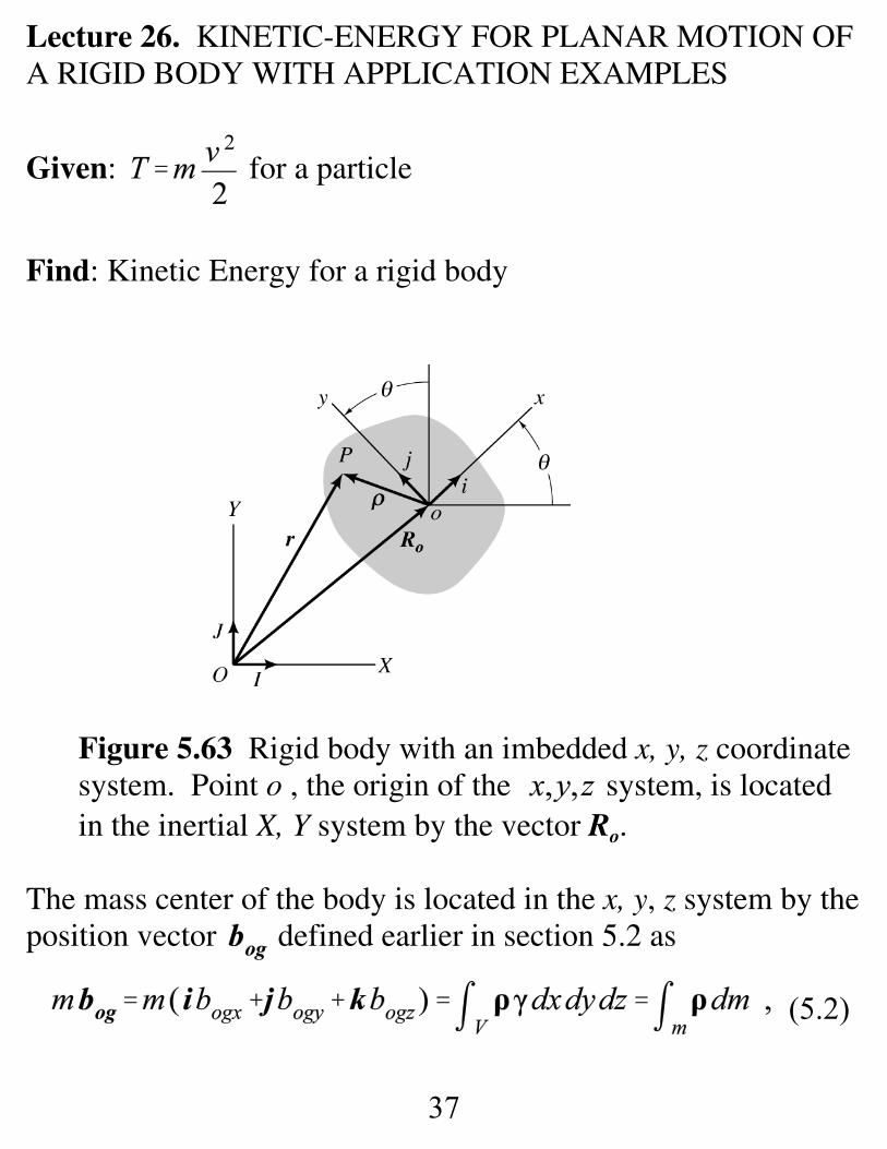
Lecture 26. KINETIC-ENERGY FOR PLANAR MOTION OFA RIGID BODY WITH APPLICATION EXAMPLES
Given: for a particle
Find: Kinetic Energy for a rigid body
Figure 5.63 Rigid body with an imbedded x, y, z coordinatesystem. Point o , the origin of the system, is locatedin the inertial X, Y system by the vector Ro.
The mass center of the body is located in the x, y, z system by theposition vector defined earlier in section 5.2 as
38
(5.178)
(5.179)
(5.180)
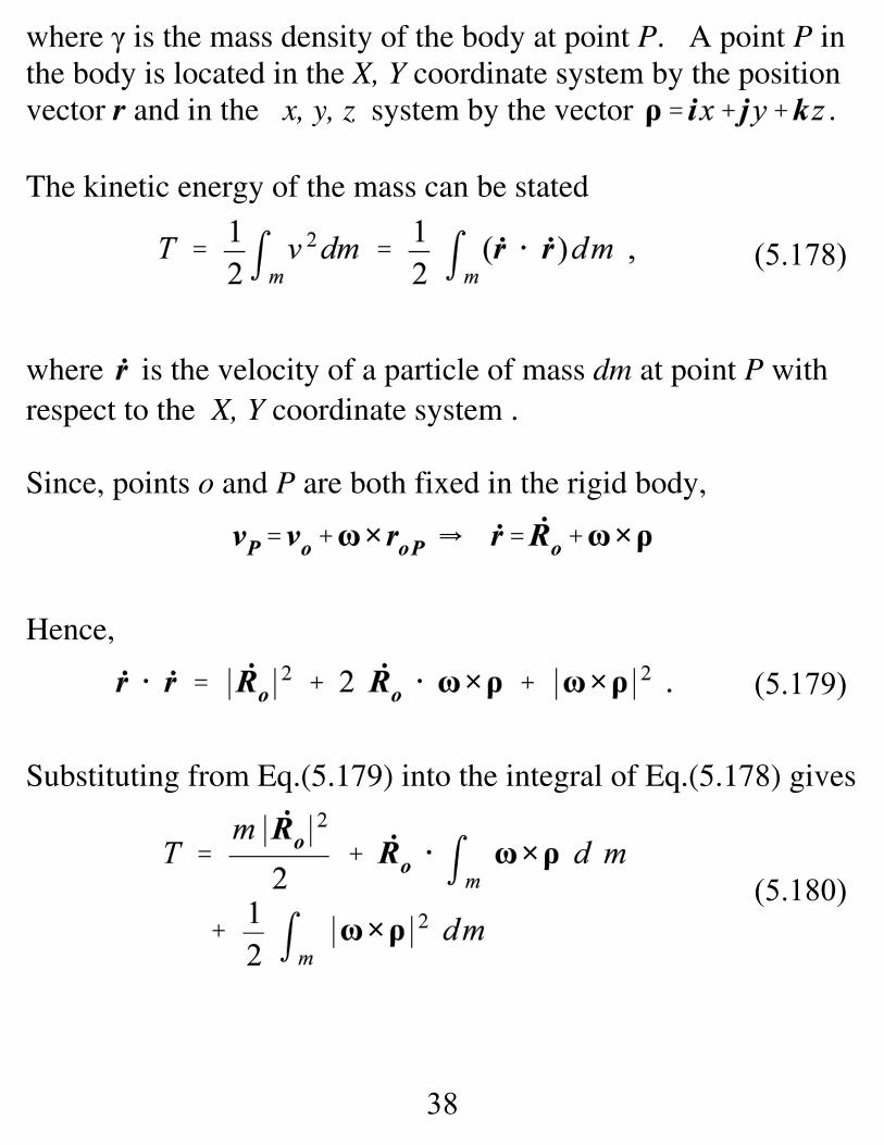
where γ is the mass density of the body at point P. A point P inthe body is located in the X, Y coordinate system by the positionvector r and in the x, y, z system by the vector .
The kinetic energy of the mass can be stated
where is the velocity of a particle of mass dm at point P withrespect to the X, Y coordinate system .
Since, points o and P are both fixed in the rigid body,
Hence,
Substituting from Eq.(5.179) into the integral of Eq.(5.178) gives
39
(5.181)
(5.182)
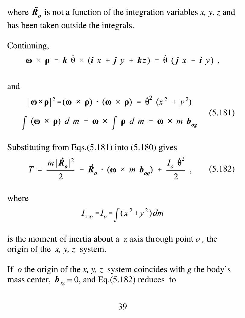
where is not a function of the integration variables x, y, z and
has been taken outside the integrals.
Continuing,
and
Substituting from Eqs.(5.181) into (5.180) gives
where
is the moment of inertia about a z axis through point o , theorigin of the x, y, z system.
If o the origin of the x, y, z system coincides with g the body’smass center, bog = 0, and Eq.(5.182) reduces to
40
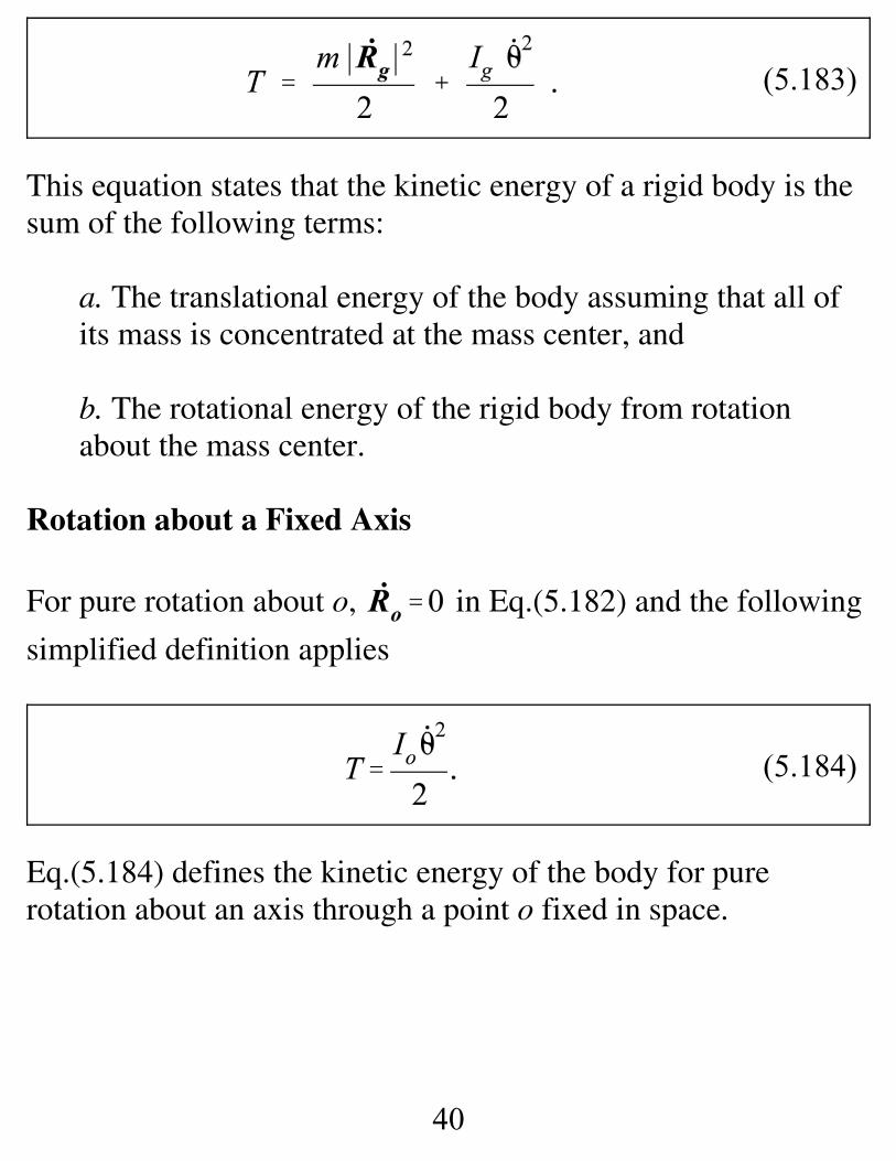
(5.183)
(5.184)
This equation states that the kinetic energy of a rigid body is thesum of the following terms:
a. The translational energy of the body assuming that all ofits mass is concentrated at the mass center, and
b. The rotational energy of the rigid body from rotationabout the mass center.
Rotation about a Fixed Axis
For pure rotation about o, in Eq.(5.182) and the following
simplified definition applies
Eq.(5.184) defines the kinetic energy of the body for purerotation about an axis through a point o fixed in space.
41
(5.207)
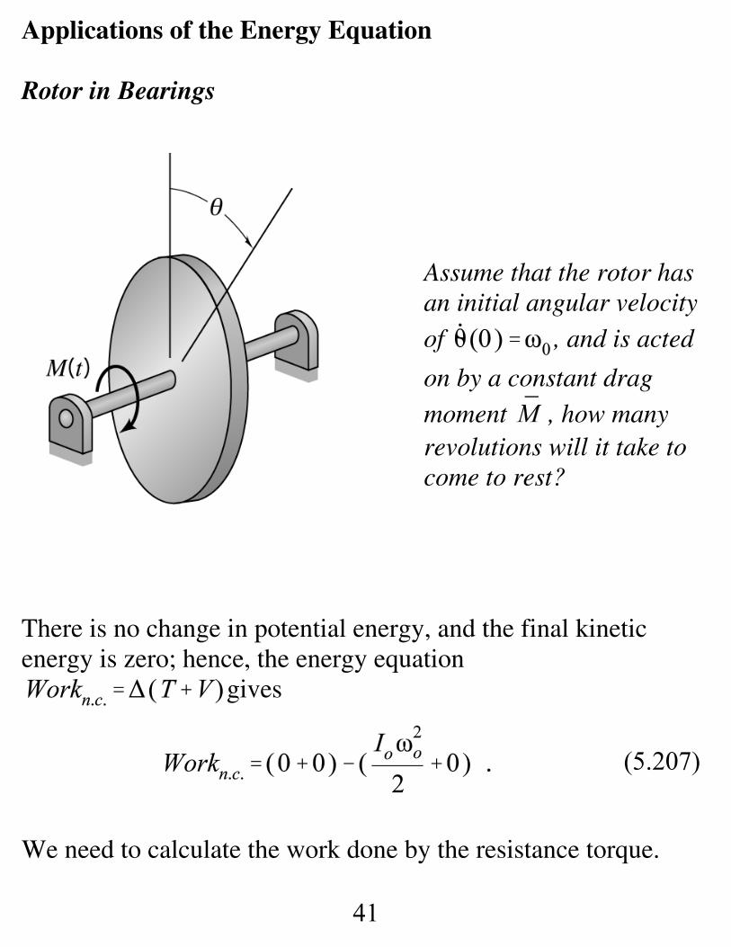
Applications of the Energy Equation
Rotor in Bearings
Assume that the rotor hasan initial angular velocityof , and is acted
on by a constant dragmoment , how manyrevolutions will it take tocome to rest?
There is no change in potential energy, and the final kineticenergy is zero; hence, the energy equation
gives
We need to calculate the work done by the resistance torque.
42
(5.210)
(5.209)
(5.208)
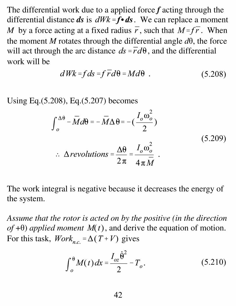
The differential work due to a applied force f acting through thedifferential distance ds is . We can replace a moment M by a force acting at a fixed radius , such that . Whenthe moment M rotates through the differential angle dθ, the forcewill act through the arc distance , and the differentialwork will be
Using Eq.(5.208), Eq.(5.207) becomes
The work integral is negative because it decreases the energy ofthe system.
Assume that the rotor is acted on by the positive (in the directionof +θ) applied moment , and derive the equation of motion. For this task, gives
43
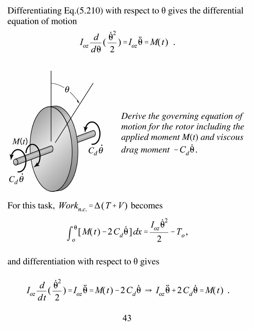
Differentiating Eq.(5.210) with respect to θ gives the differentialequation of motion
Derive the governing equation ofmotion for the rotor including theapplied moment M(t) and viscousdrag moment .
For this task, becomes
and differentiation with respect to θ gives
44
(5.211)
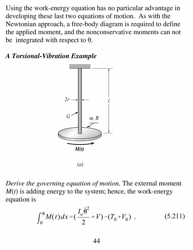
Using the work-energy equation has no particular advantage indeveloping these last two equations of motion. As with theNewtonian approach, a free-body diagram is required to definethe applied moment, and the nonconservative moments can notbe integrated with respect to θ.
A Torsional-Vibration Example
Derive the governing equation of motion. The external momentM(t) is adding energy to the system; hence, the work-energyequation is
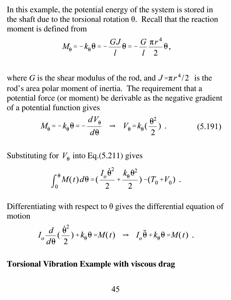
45
(5.191)
In this example, the potential energy of the system is stored inthe shaft due to the torsional rotation θ. Recall that the reactionmoment is defined from
where G is the shear modulus of the rod, and is therod’s area polar moment of inertia. The requirement that apotential force (or moment) be derivable as the negative gradientof a potential function gives
Substituting for into Eq.(5.211) gives
Differentiating with respect to θ gives the differential equation ofmotion
Torsional Vibration Example with viscous drag
46
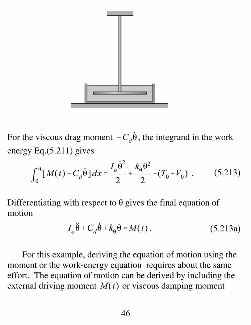
(5.213)
(5.213a)
For the viscous drag moment , the integrand in the work-
energy Eq.(5.211) gives
Differentiating with respect to θ gives the final equation ofmotion
For this example, deriving the equation of motion using themoment or the work-energy equation requires about the sameeffort. The equation of motion can be derived by including theexternal driving moment or viscous damping moment
47
(5.214)
(5.215)
in the work integral, but the integral is now a function of
t or , not θ, and can not be integrated.
Recall that the moment equation gave
where is the resultant moment about the vertical axis.
Substituting the energy-integral substitution yields
Multiplying through by dθ and integrating gives
This result coincides with Eq.(5.213a), obtained from the work-energy-equation.
48
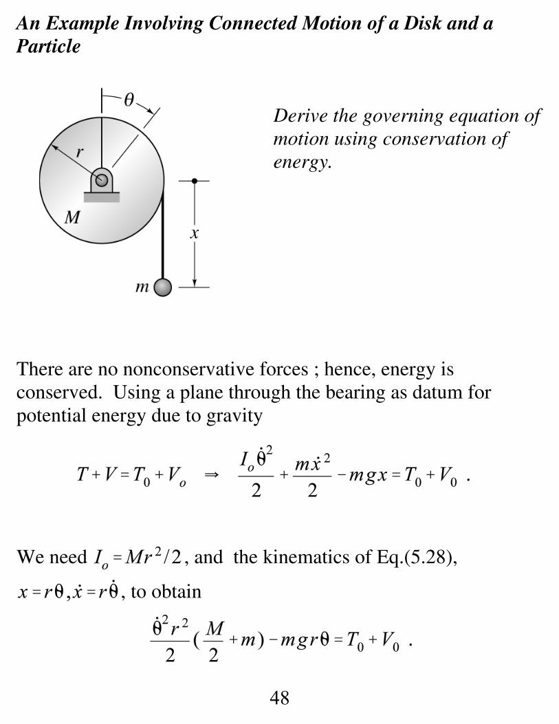
An Example Involving Connected Motion of a Disk and aParticle
Derive the governing equation ofmotion using conservation ofenergy.
There are no nonconservative forces ; hence, energy isconserved. Using a plane through the bearing as datum forpotential energy due to gravity
We need , and the kinematics of Eq.(5.28),
, to obtain
49
Differentiating with respect to θ gives the differential equation ofmotion
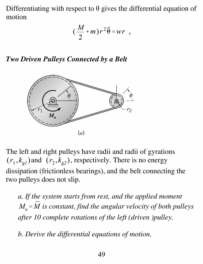
Two Driven Pulleys Connected by a Belt
The left and right pulleys have radii and radii of gyrationsand , respectively. There is no energy
dissipation (frictionless bearings), and the belt connecting thetwo pulleys does not slip.
a. If the system starts from rest, and the applied moment is constant, find the angular velocity of both pulleys
after 10 complete rotations of the left (driven )pulley.
b. Derive the differential equations of motion.
50
(5.195)
(5.196)
(5.197)
There is no change in the potential energy of this system; hence, yields
Since the belt does not slip, the tangential velocities at the rimsof the pulleys must equal, providing the kinematic condition,
, which reduces Eq.(5.195) to
Using to define the work integral on the left-handside gives
and the angular velocity after the moment has been applied forten rotations is
which concludes Task a. The work integral is positive in
51
Eq.(5.197) because it is increasing the mechanical energy of thesystem.
Differentiating Eq.(5.197) with respect to θ gives thegoverning differential equation of motion
which coincides with our earlier result and concludes Task b.
52
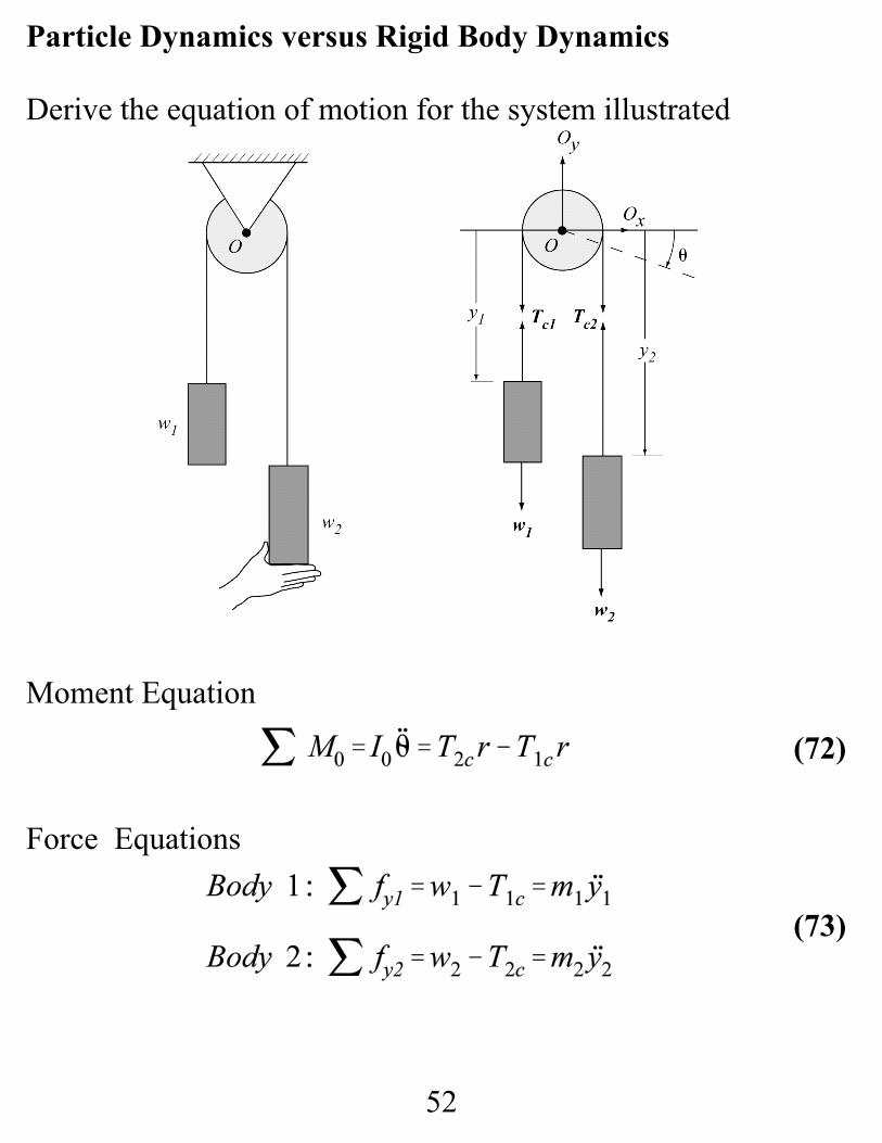
Particle Dynamics versus Rigid Body Dynamics
Derive the equation of motion for the system illustrated
Moment Equation
Force Equations
(72)
(73)
53
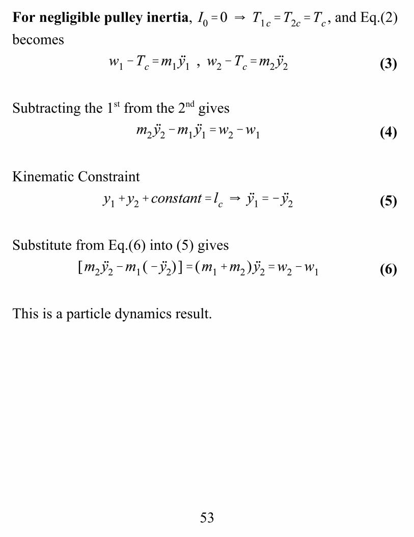
For negligible pulley inertia, , and Eq.(2)becomes
Subtracting the 1st from the 2nd gives
Kinematic Constraint
Substitute from Eq.(6) into (5) gives
This is a particle dynamics result.
(3)
(4)
(5)
(6)
54
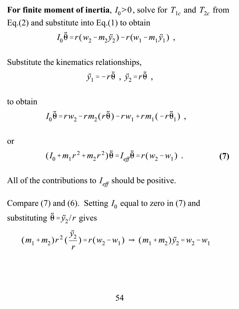
For finite moment of inertia, , solve for and fromEq.(2) and substitute into Eq.(1) to obtain
Substitute the kinematics relationships,
to obtain
or
All of the contributions to should be positive.
Compare (7) and (6). Setting equal to zero in (7) and
substituting gives
(7)
55
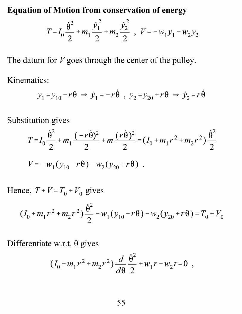
Equation of Motion from conservation of energy
The datum for V goes through the center of the pulley.
Kinematics:
Substitution gives
Hence, gives
Differentiate w.r.t. θ gives
56
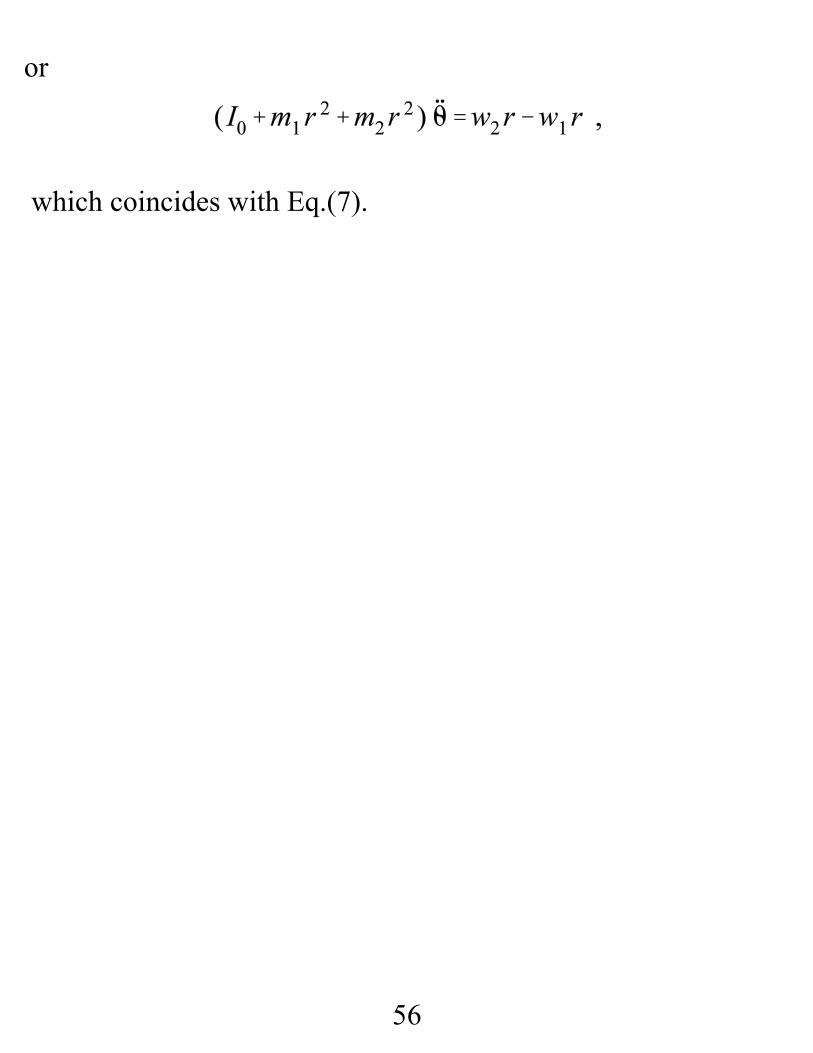
or
which coincides with Eq.(7).
58
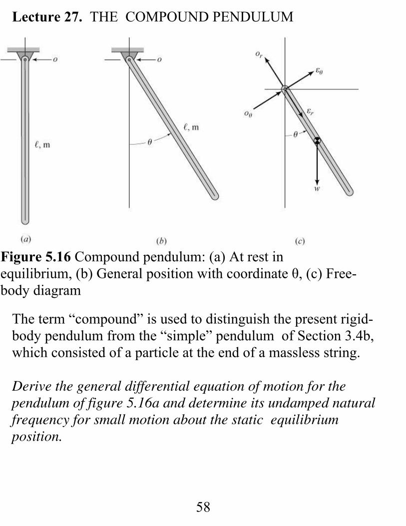
Figure 5.16 Compound pendulum: (a) At rest inequilibrium, (b) General position with coordinate θ, (c) Free-body diagram
Lecture 27. THE COMPOUND PENDULUM
The term “compound” is used to distinguish the present rigid-body pendulum from the “simple” pendulum of Section 3.4b,which consisted of a particle at the end of a massless string.
Derive the general differential equation of motion for thependulum of figure 5.16a and determine its undamped naturalfrequency for small motion about the static equilibrium position.
59
(5.33)
(5.34)
(5.35)
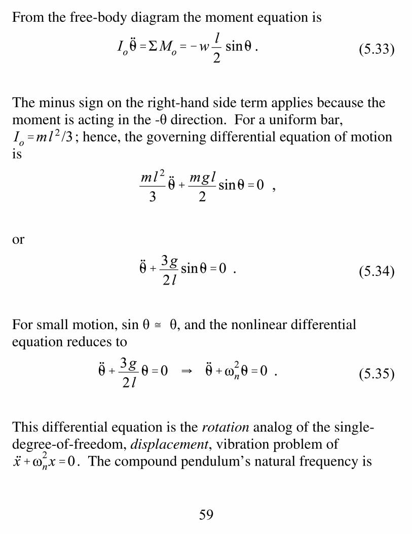
From the free-body diagram the moment equation is
The minus sign on the right-hand side term applies because themoment is acting in the -θ direction. For a uniform bar,
; hence, the governing differential equation of motionis
or
For small motion, sin θ – θ, and the nonlinear differentialequation reduces to
This differential equation is the rotation analog of the single-degree-of-freedom, displacement, vibration problem of
. The compound pendulum’s natural frequency is
60
(5.36)
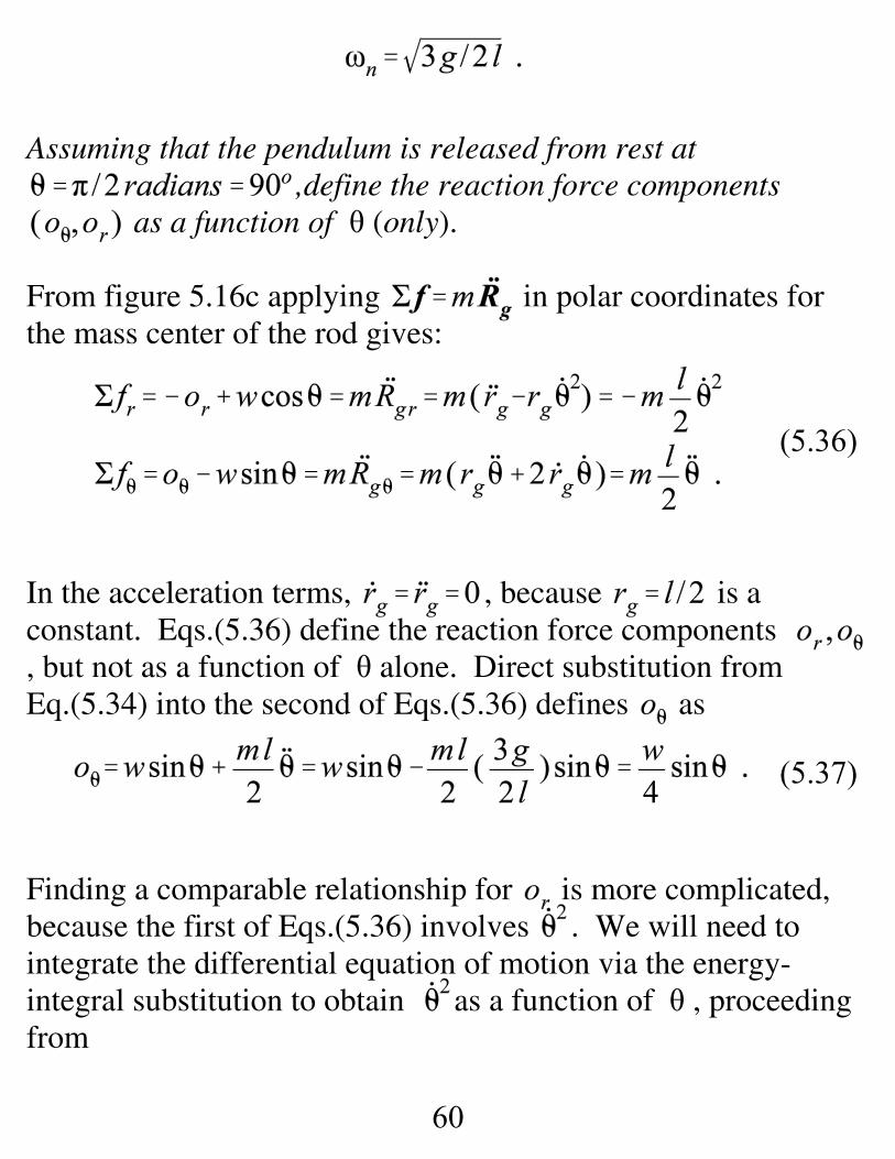
(5.37)
Assuming that the pendulum is released from rest at,define the reaction force components
as a function of θ (only).
From figure 5.16c applying in polar coordinates forthe mass center of the rod gives:
In the acceleration terms, , because is aconstant. Eqs.(5.36) define the reaction force components , but not as a function of θ alone. Direct substitution fromEq.(5.34) into the second of Eqs.(5.36) defines as
Finding a comparable relationship for is more complicated,because the first of Eqs.(5.36) involves . We will need tointegrate the differential equation of motion via the energy-integral substitution to obtain as a function of θ , proceedingfrom
61
(5.38)
(5.39)
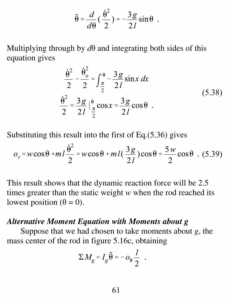
Multiplying through by dθ and integrating both sides of thisequation gives
Substituting this result into the first of Eq.(5.36) gives
This result shows that the dynamic reaction force will be 2.5times greater than the static weight w when the rod reached itslowest position (θ = 0).
Alternative Moment Equation with Moments about gSuppose that we had chosen to take moments about g, the
mass center of the rod in figure 5.16c, obtaining
62
(5.40)
The moment has a negative sign because it is acting in the -θdirection. In this equation, the required moment of inertia aboutg is Substituting for oθ from Eq.(5.37) gives
or
Writing the moment equation about g involves more work butgets tha same equation. Note in the intermediate step ofEq.(5.40) that we are accomplishing the parallel-axis formula inmoving from to , via
where bgo is the vector from themass center g to the pivot point o.
Deriving The Equation of Motion From The Energy EquationThere are no external time varying forces or moments and no
energy dissipation; hence, mechanical energy is conserved; i.e.,. Using a horizontal plane through the pendulum’s
pivot point as a datum for gravity potential energy gives
63
For rotation about the fixed point o, the kinetic energy of thependulum is defined by
Hence,
Differentiating w.r.t. θ gives
64
(5.41)
Static stability about equilibrium points.
From
Equilibrium for small Motion about the equilibriumposition . Small motion about the equilibrium position gives thelinearized differential equation of motion
For the initial conditions, , the solution to thelinearized Eq.(5.35) can be stated
consisting of a stable oscillation at the natural frequency. Hence,is said to be a stable equilibrium point for the body.
65
(5.34)
(5.42)
(5.43)
Equilibrium for small Motion about the equilibrium position
Motion is governed by the nonlinear equation of motion,
Expanding in a Taylor’s series about gives
Retaining only the linear term in Eq.(5.42) and substituting backinto Eq.(5.34) gives
Observe the negative sign in the coefficient for . If this werea harmonic oscillator consisting of a spring supporting a mass, acomparable negative sign would imply a negative stiffness,yielding a differential equation of the form
66
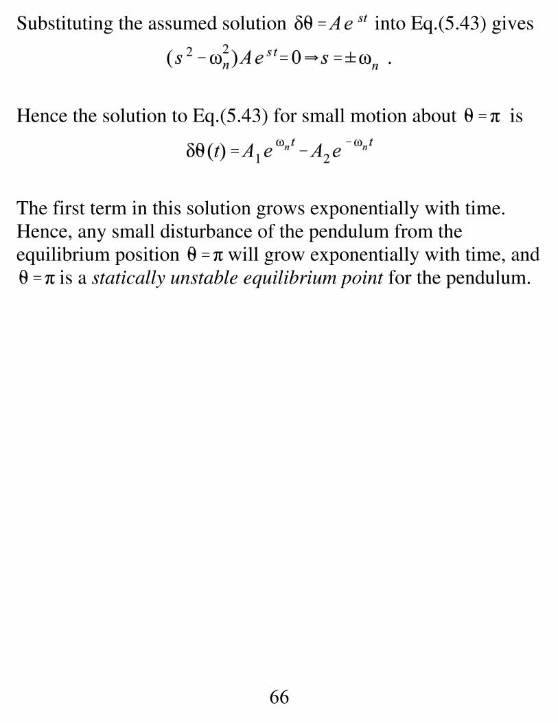
Substituting the assumed solution into Eq.(5.43) gives
Hence the solution to Eq.(5.43) for small motion about is
The first term in this solution grows exponentially with time. Hence, any small disturbance of the pendulum from theequilibrium position will grow exponentially with time, and
is a statically unstable equilibrium point for the pendulum.
67
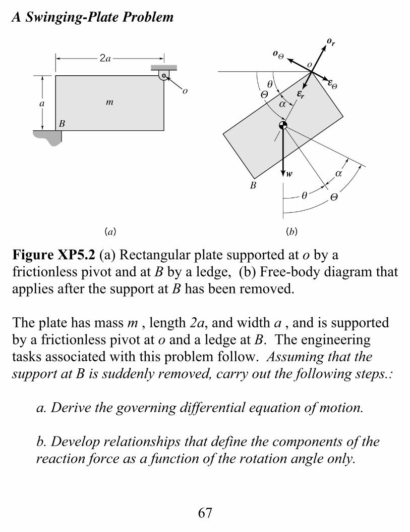
A Swinging-Plate Problem
Figure XP5.2 (a) Rectangular plate supported at o by africtionless pivot and at B by a ledge, (b) Free-body diagram thatapplies after the support at B has been removed.
The plate has mass m , length 2a, and width a , and is supportedby a frictionless pivot at o and a ledge at B. The engineeringtasks associated with this problem follow. Assuming that thesupport at B is suddenly removed, carry out the following steps.:
a. Derive the governing differential equation of motion.
b. Develop relationships that define the components of thereaction force as a function of the rotation angle only.
68
(5.56)
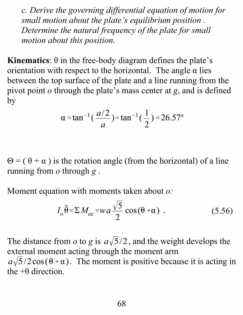
c. Derive the governing differential equation of motion forsmall motion about the plate’s equilibrium position . Determine the natural frequency of the plate for smallmotion about this position.
Kinematics: θ in the free-body diagram defines the plate’sorientation with respect to the horizontal. The angle α liesbetween the top surface of the plate and a line running from thepivot point o through the plate’s mass center at g, and is definedby
Θ = ( θ + α ) is the rotation angle (from the horizontal) of a linerunning from o through g .
Moment equation with moments taken about o:
The distance from o to g is , and the weight develops theexternal moment acting through the moment arm
. The moment is positive because it is acting inthe +θ direction.
69
(5.57)
(5.58)
(5.59)
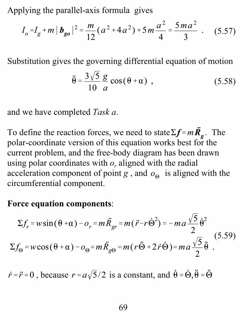
Applying the parallel-axis formula gives
Substitution gives the governing differential equation of motion
and we have completed Task a.
To define the reaction forces, we need to state . Thepolar-coordinate version of this equation works best for thecurrent problem, and the free-body diagram has been drawnusing polar coordinates with or aligned with the radialacceleration component of point g , and is aligned with thecircumferential component.
Force equation components:
, because is a constant, and
70
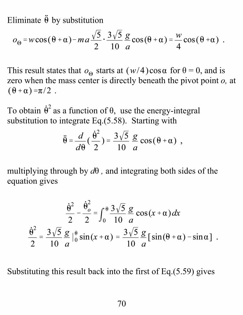
Eliminate by substitution
This result states that starts at for θ = 0, and iszero when the mass center is directly beneath the pivot point o, at
.
To obtain as a function of θ, use the energy-integralsubstitution to integrate Eq.(5.58). Starting with
multiplying through by dθ , and integrating both sides of theequation gives
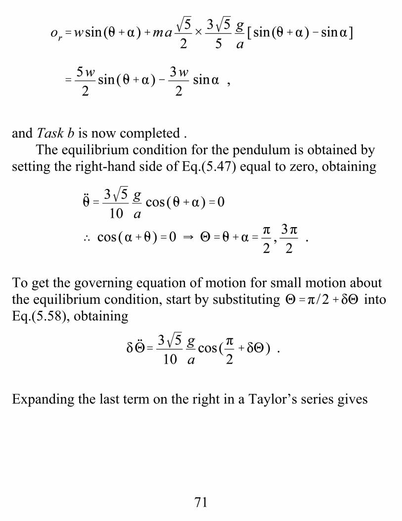
Substituting this result back into the first of Eq.(5.59) gives
71
and Task b is now completed .The equilibrium condition for the pendulum is obtained by
setting the right-hand side of Eq.(5.47) equal to zero, obtaining
To get the governing equation of motion for small motion aboutthe equilibrium condition, start by substituting intoEq.(5.58), obtaining
Expanding the last term on the right in a Taylor’s series gives
72
(5.60)
Retaining only the linear term in this expansion gives thelinearized differential equation of motion
hence, the natural frequency is defined by
73
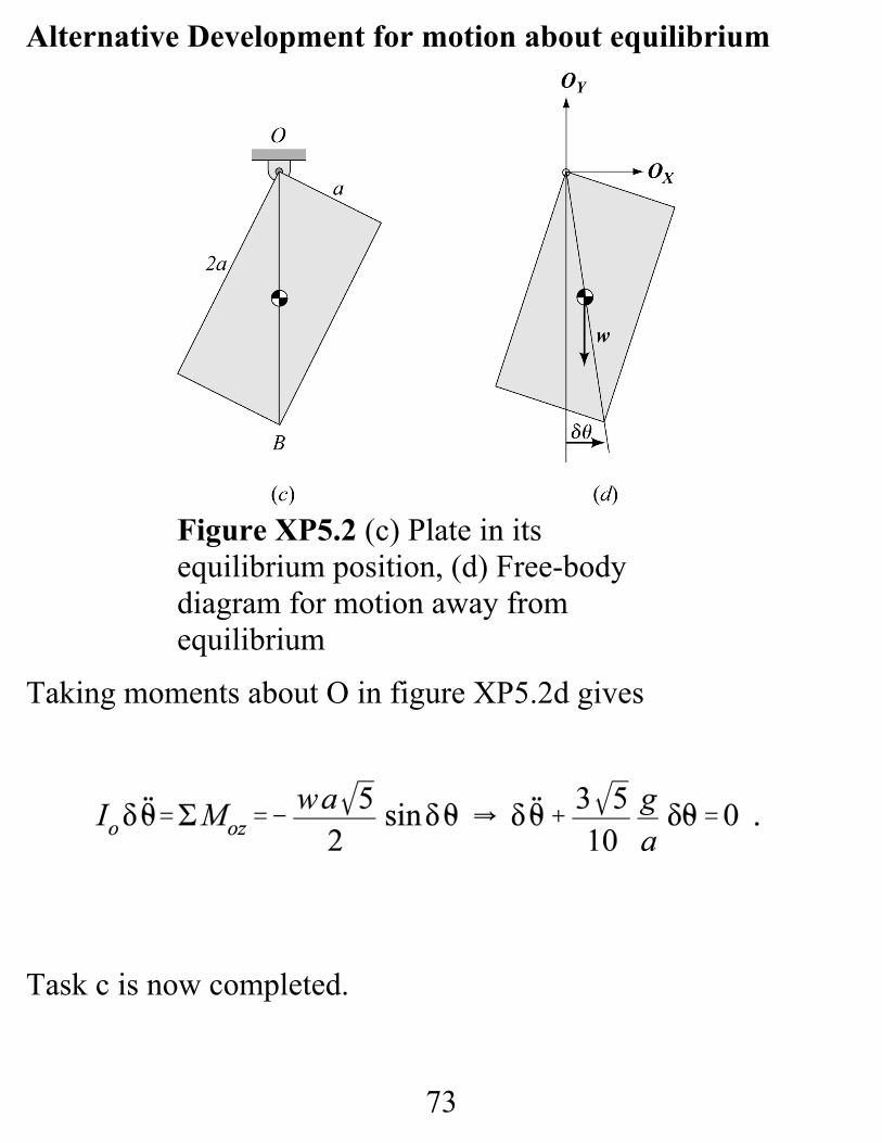
Alternative Development for motion about equilibrium
Taking moments about O in figure XP5.2d gives
Task c is now completed.
Figure XP5.2 (c) Plate in itsequilibrium position, (d) Free-bodydiagram for motion away fromequilibrium
74
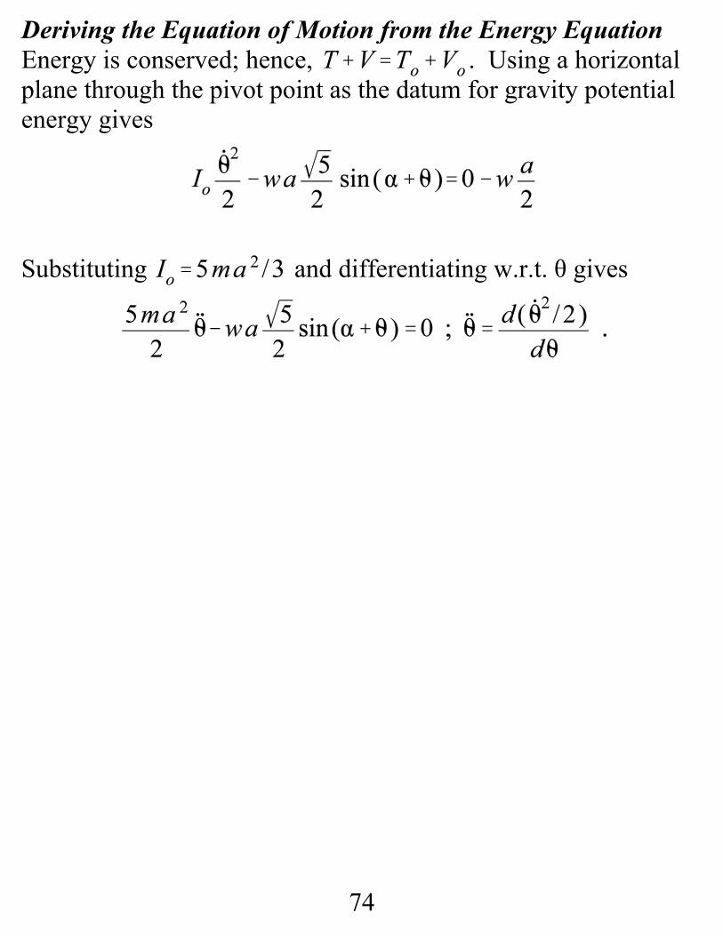
Deriving the Equation of Motion from the Energy EquationEnergy is conserved; hence, . Using a horizontalplane through the pivot point as the datum for gravity potentialenergy gives
Substituting and differentiating w.r.t. θ gives
75
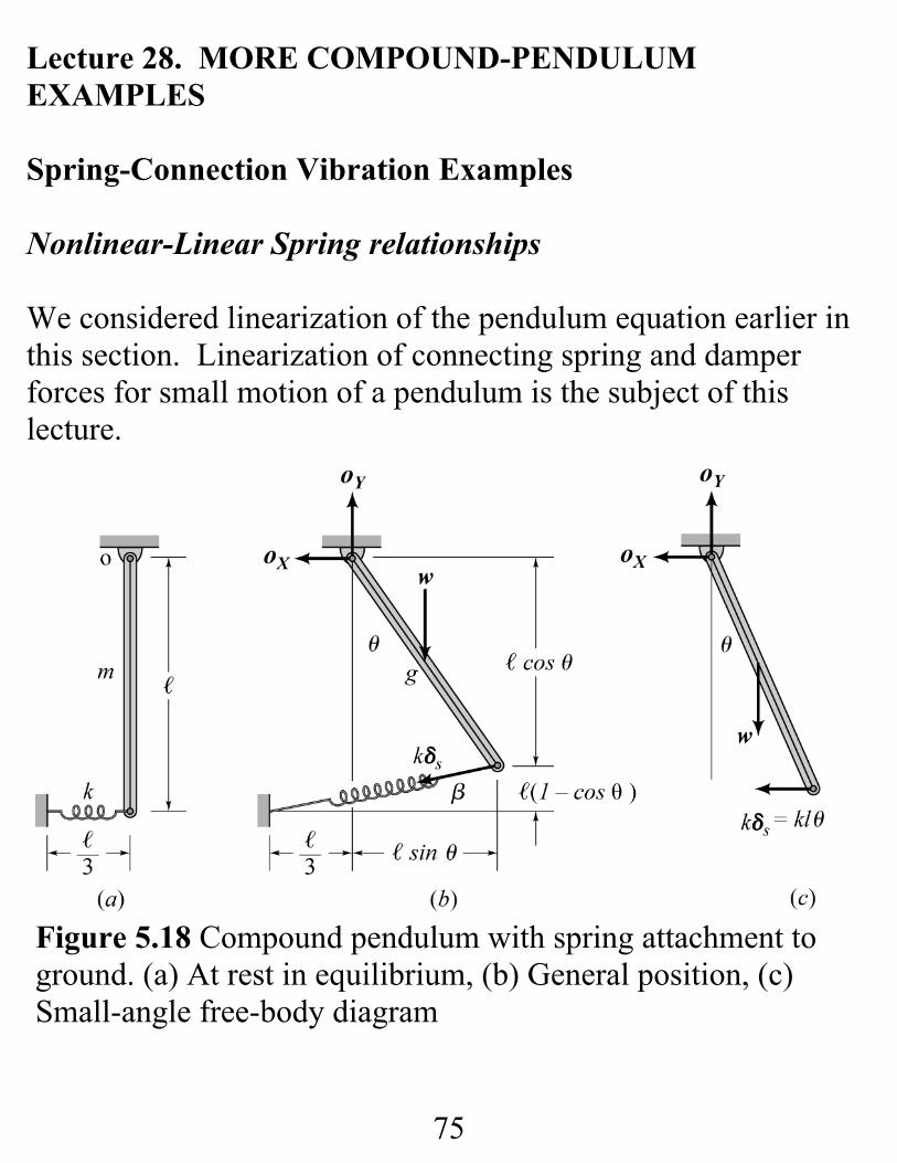
Lecture 28. MORE COMPOUND-PENDULUMEXAMPLES
Spring-Connection Vibration Examples
Nonlinear-Linear Spring relationships
We considered linearization of the pendulum equation earlier inthis section. Linearization of connecting spring and damperforces for small motion of a pendulum is the subject of thislecture.
Figure 5.18 Compound pendulum with spring attachment toground. (a) At rest in equilibrium, (b) General position, (c)Small-angle free-body diagram
76
(5.56)
(5.57)
The spring has length and is undeflected at . Thefollowing engineering-analysis tasks apply:
a. Draw free-body diagrams and derive the EOM
b. For small θ develop the linearized EOM.
Figure 5.18B provides the free-body diagram illustrating thestretched spring. The deflected spring length is
Hence, the spring force is
and it acts at the angle β from the horizontal defined by
77
(5.58)
The pendulum equation of motion is obtained by a momentequation about the pivot point, yielding
Substituting for ( plus a considerable amount ofalgebra) yields
This is a “geometric” nonlinearity. The spring is linear, but thefinite θ rotation causes a nonlinearity.
For small θ, expanding with defined byEq.(5.56) in a Taylor’s series expansion gives . Also, forsmall θ, a Taylor series expansion gives ;hence, for small θ, the spring force actsperpendicular to the pendulum axis. For small θ, the momentequation reduces to
78
(5.59)
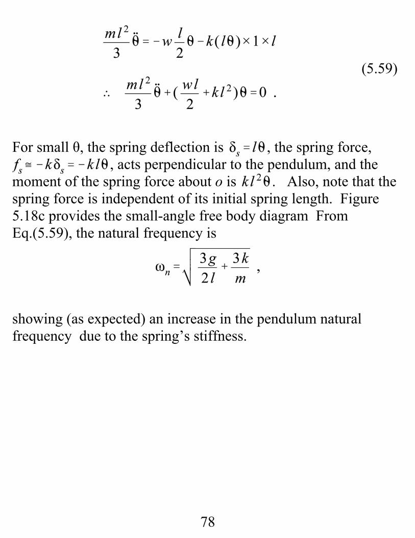
For small θ, the spring deflection is , the spring force,, acts perpendicular to the pendulum, and the
moment of the spring force about o is . Also, note that thespring force is independent of its initial spring length. Figure5.18c provides the small-angle free body diagram FromEq.(5.59), the natural frequency is
showing (as expected) an increase in the pendulum naturalfrequency due to the spring’s stiffness.
79
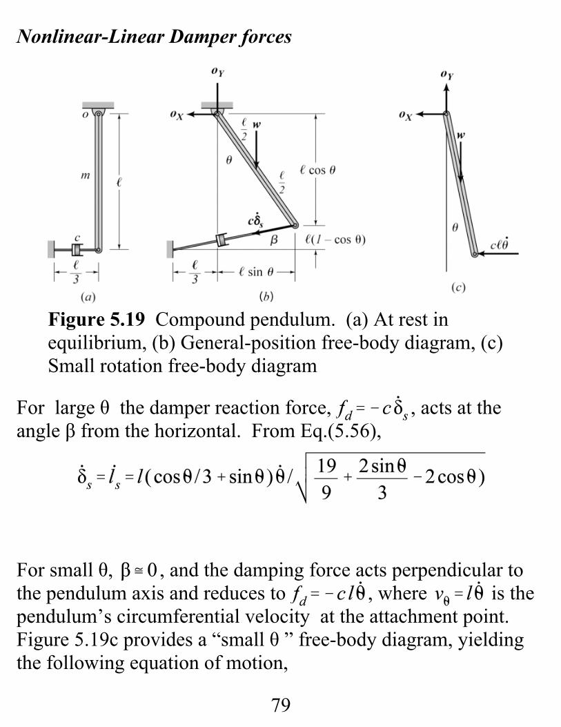
Figure 5.19 Compound pendulum. (a) At rest inequilibrium, (b) General-position free-body diagram, (c)Small rotation free-body diagram
Nonlinear-Linear Damper forces
For large θ the damper reaction force, , acts at theangle β from the horizontal. From Eq.(5.56),
For small θ, , and the damping force acts perpendicular tothe pendulum axis and reduces to , where is thependulum’s circumferential velocity at the attachment point. Figure 5.19c provides a “small θ ” free-body diagram, yieldingthe following equation of motion,
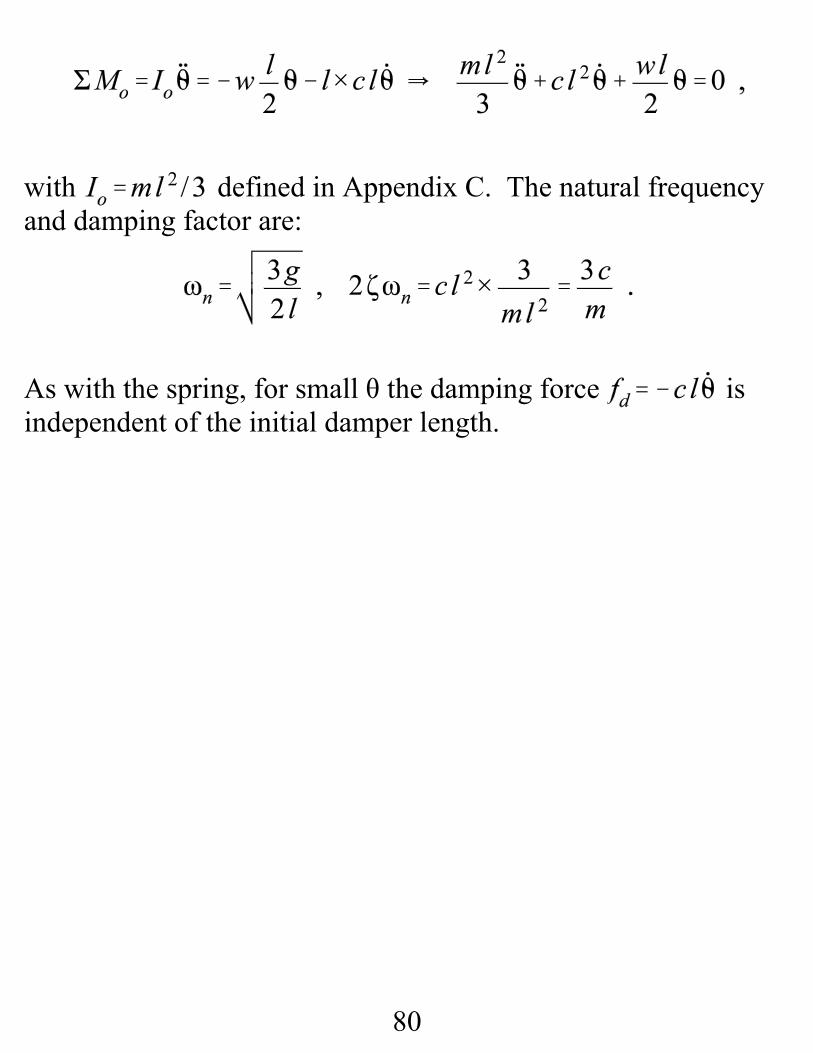
80
with defined in Appendix C. The natural frequencyand damping factor are:
As with the spring, for small θ the damping force isindependent of the initial damper length.
81
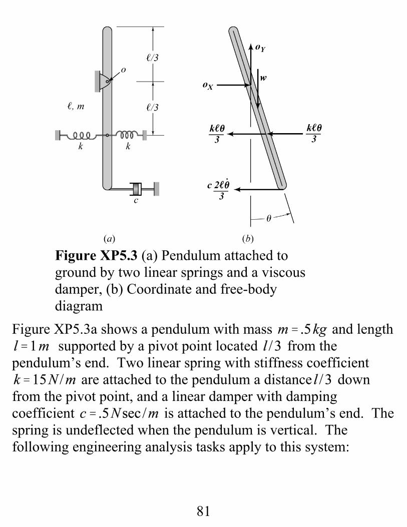
Figure XP5.3a shows a pendulum with mass and length supported by a pivot point located from the
pendulum’s end. Two linear spring with stiffness coefficient are attached to the pendulum a distance down
from the pivot point, and a linear damper with dampingcoefficient is attached to the pendulum’s end. Thespring is undeflected when the pendulum is vertical. Thefollowing engineering analysis tasks apply to this system:
Figure XP5.3 (a) Pendulum attached toground by two linear springs and a viscousdamper, (b) Coordinate and free-bodydiagram
82
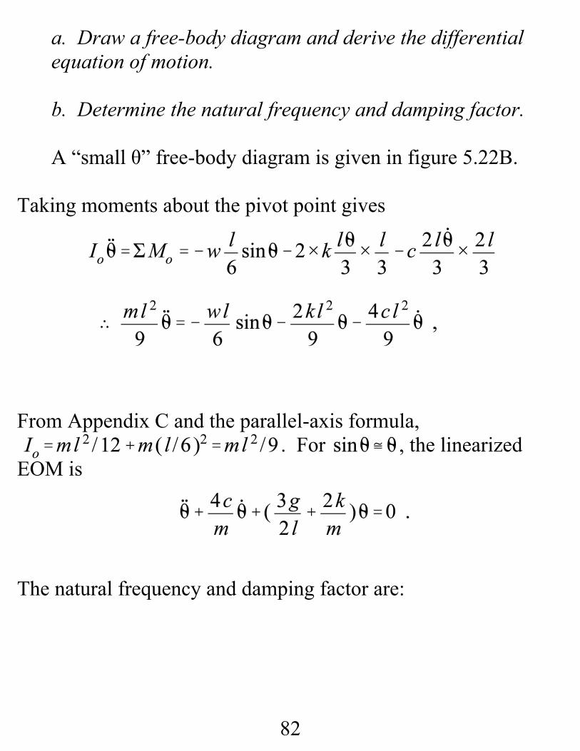
a. Draw a free-body diagram and derive the differentialequation of motion.
b. Determine the natural frequency and damping factor.
A “small θ” free-body diagram is given in figure 5.22B.
Taking moments about the pivot point gives
From Appendix C and the parallel-axis formula, . For , the linearizedEOM is
The natural frequency and damping factor are:
83
EOM from Energy, neglecting damping
Select datum through pivot point; hence, .
Differentiating w.r.t. θ gives
, and for small θ,
84
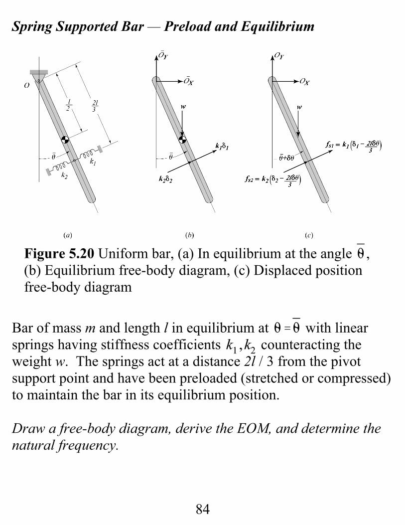
Spring Supported Bar — Preload and Equilibrium
Bar of mass m and length l in equilibrium at with linearsprings having stiffness coefficients counteracting theweight w. The springs act at a distance 2l / 3 from the pivotsupport point and have been preloaded (stretched or compressed)to maintain the bar in its equilibrium position.
Draw a free-body diagram, derive the EOM, and determine thenatural frequency.
Figure 5.20 Uniform bar, (a) In equilibrium at the angle ,(b) Equilibrium free-body diagram, (c) Displaced positionfree-body diagram
85
(5.84)
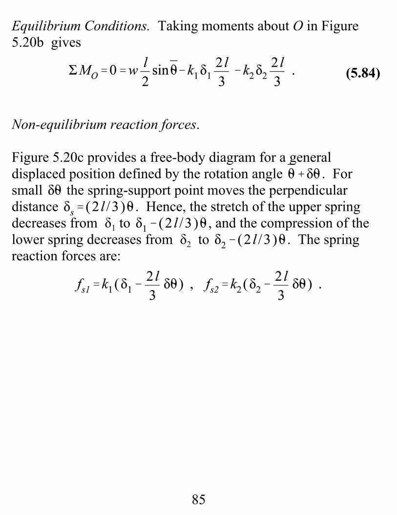
Equilibrium Conditions. Taking moments about O in Figure5.20b gives
Non-equilibrium reaction forces.
Figure 5.20c provides a free-body diagram for a generaldisplaced position defined by the rotation angle . Forsmall the spring-support point moves the perpendiculardistance . Hence, the stretch of the upper springdecreases from δ1 to , and the compression of thelower spring decreases from δ2 to . The springreaction forces are:
86
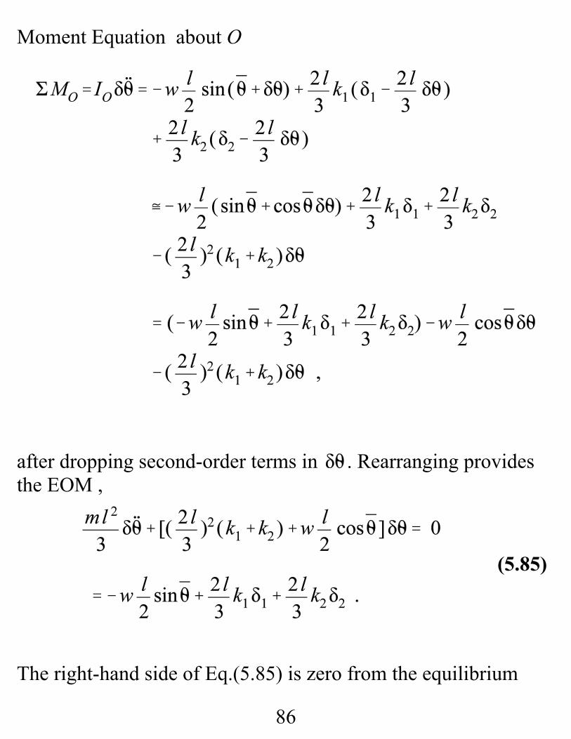
(5.85)
Moment Equation about O
after dropping second-order terms in . Rearranging providesthe EOM ,
The right-hand side of Eq.(5.85) is zero from the equilibrium
87
(5.87)
(5.86)
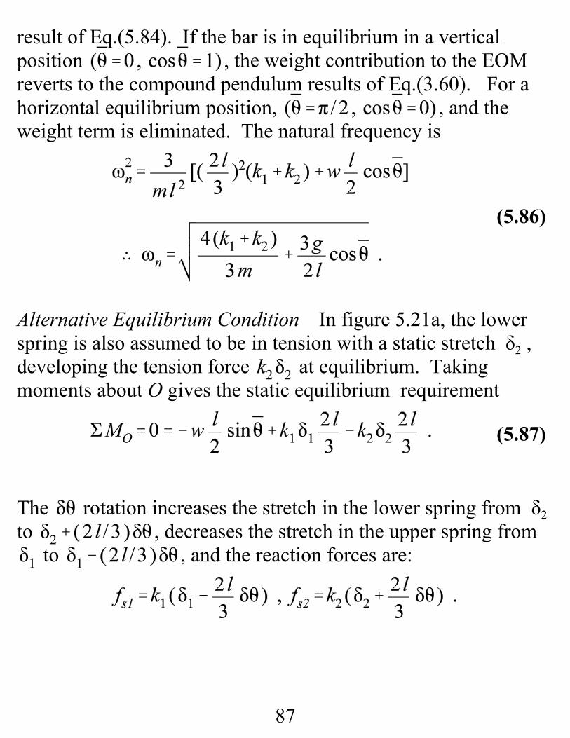
result of Eq.(5.84). If the bar is in equilibrium in a verticalposition , the weight contribution to the EOMreverts to the compound pendulum results of Eq.(3.60). For ahorizontal equilibrium position, , and theweight term is eliminated. The natural frequency is
Alternative Equilibrium Condition In figure 5.21a, the lowerspring is also assumed to be in tension with a static stretch δ2 ,developing the tension force at equilibrium. Takingmoments about O gives the static equilibrium requirement
The rotation increases the stretch in the lower spring from δ2 to , decreases the stretch in the upper spring from
to , and the reaction forces are:
88
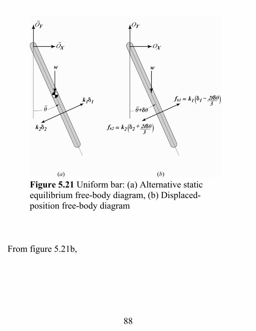
Figure 5.21 Uniform bar: (a) Alternative staticequilibrium free-body diagram, (b) Displaced-position free-body diagram
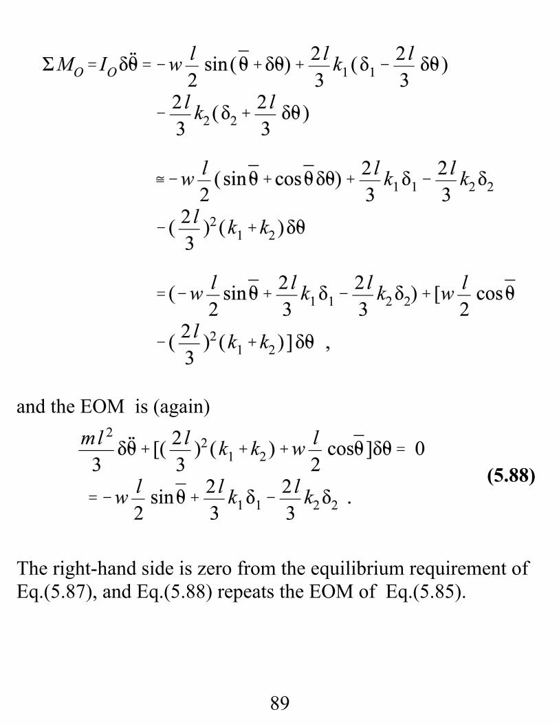
From figure 5.21b,
89
(5.88)
and the EOM is (again)
The right-hand side is zero from the equilibrium requirement ofEq.(5.87), and Eq.(5.88) repeats the EOM of Eq.(5.85).
90
The lesson from this second development is: For smallmotion about equilibrium, the same EOM is obtainedirrespective of the initial equilibrium forces in the (linear)springs. The spring-force contributions to the differentialequation arise from the change in the equilibrium forces due to achange in position. This is the same basic outcome that weobtained for a mass m supported by linear springs in figure 3.7. The change in equilibrium angle changes w’s contribution tothe EOM , because , the moment due to w, is anonlinear function of θ.
91
(5.24)
(5.26)
Prescribed acceleration of a Pivot Support Point Moment equations for the fixed-axis rotation problems of
the preceding section were taken about a fixed pivot point,employing the moment equation
where o identifies the axis of rotation. The problems involvedin this short section concerns situations where the pivot point isaccelerating, and the general moment equation,
is required. In applying Eq.(5.24), recall the following points:a. Moments are being taken about the body-fixed axis o ,and Io is the moment of inertia through axis o .
b. The vector bog goes from a z axis through o to a z axisthrough the mass center at g.
c. The positive rotation and moment sense in Eq.(5.24)correspond to a counter clockwise rotation for θ.
The last term in the moment equation is positive because thepositive right-hand-rule convention for the cross-product in thisterm coincides with the +θ sense. For a rigid body with apositive clockwise rotation angle this last term requires anegative sign.
92
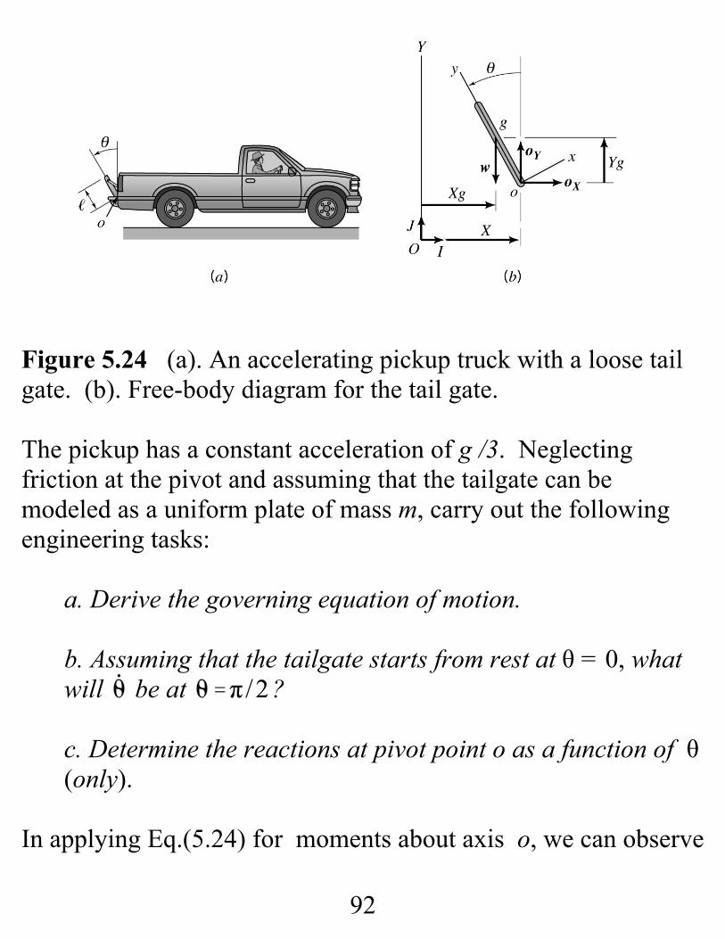
Figure 5.24 (a). An accelerating pickup truck with a loose tailgate. (b). Free-body diagram for the tail gate.
The pickup has a constant acceleration of g /3. Neglectingfriction at the pivot and assuming that the tailgate can bemodeled as a uniform plate of mass m, carry out the followingengineering tasks:
a. Derive the governing equation of motion.
b. Assuming that the tailgate starts from rest at θ = 0, whatwill be at ?
c. Determine the reactions at pivot point o as a function of θ(only).
In applying Eq.(5.24) for moments about axis o, we can observe
93
(5.61)
(5.62)
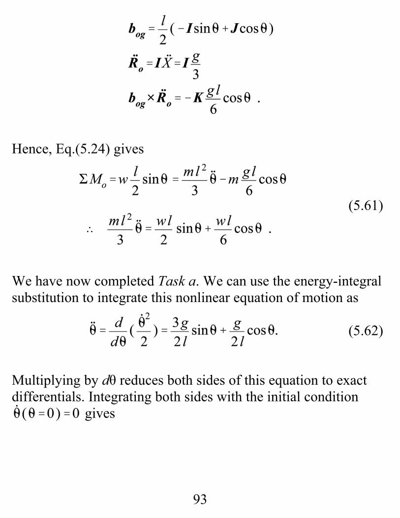
Hence, Eq.(5.24) gives
We have now completed Task a. We can use the energy-integralsubstitution to integrate this nonlinear equation of motion as
Multiplying by dθ reduces both sides of this equation to exactdifferentials. Integrating both sides with the initial condition
gives
94
(5.63)
(5.64)
Hence, at θ = π / 2 , and we have completedTask b. We used the energy-integral substitution, but note thatthe tail gate’s mechanical energy energy is not conserved. Thetruck’s acceleration is adding energy to the tail gate.
Moving on to Task c, stating for the mass centergives:
We need to determine in these equations. From figure5.19B,
Differentiating twice with respect to time gives:
95
(5.65)
Substituting into Eqs.(5.64) gives:
where has been replaced with , the pick-up truck’sacceleration. Substituting from Eqs.(5.62) and (5.63) for and
, respectively, (and some algebra) gives:
and completes Task c. The decision to use the general moment Eq.(5.24) and sum
moments about the pivot point o instead of the mass center gsaves a great deal of effort in arriving at the differential equationof motion. To confirm this statement, consider the followingmoment equation about g
96
Substituting from Eq.(5.65) for gives
Gathering like terms gives
Simplifying these equations gives Eq.(5.62) ,the originaldifferential equation of motion.
The lesson from this short section is: In problems where apivot support point has a prescribed acceleration, stating themoment equation (correctly) about the pivot point will lead tothe governing equation of motion much more quickly and easilythan taking moments about the mass center.
Note: Energy is not conserved with base acceleration!
96
(5.15)
(5.24)
(5.25)
(5.26)
(5.205)
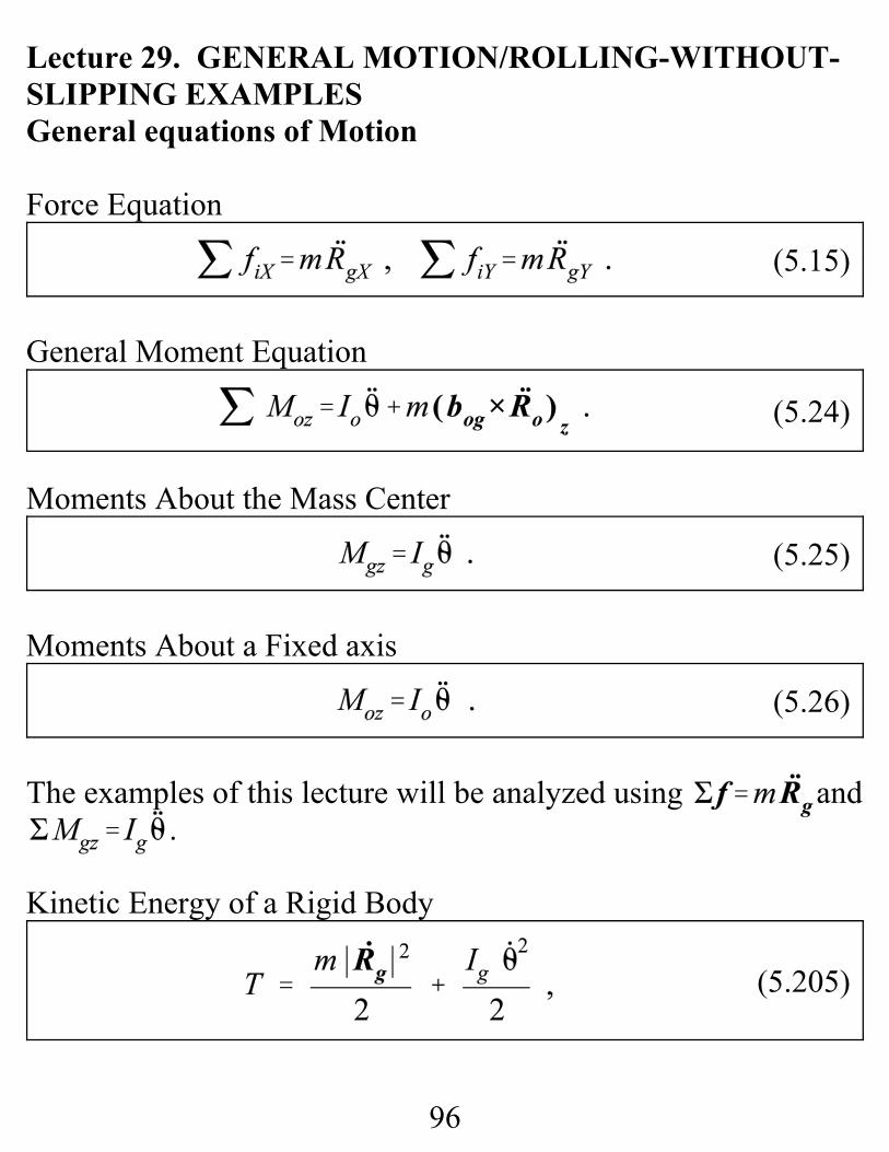
Lecture 29. GENERAL MOTION/ROLLING-WITHOUT-SLIPPING EXAMPLESGeneral equations of Motion
Force Equation
General Moment Equation
Moments About the Mass Center
Moments About a Fixed axis
The examples of this lecture will be analyzed using and.
Kinetic Energy of a Rigid Body
97
(5.75)
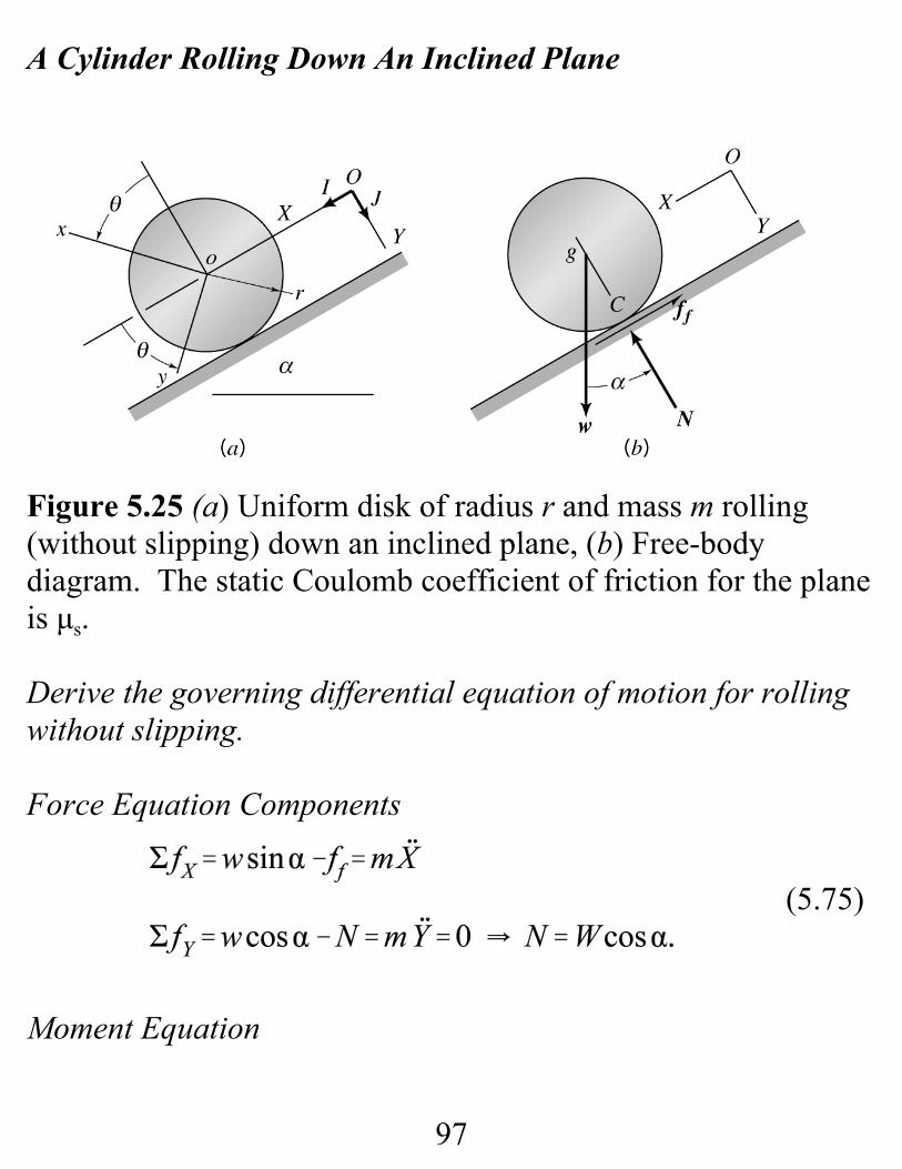
A Cylinder Rolling Down An Inclined Plane
Figure 5.25 (a) Uniform disk of radius r and mass m rolling(without slipping) down an inclined plane, (b) Free-bodydiagram. The static Coulomb coefficient of friction for the planeis μs.
Derive the governing differential equation of motion for rollingwithout slipping.
Force Equation Components
Moment Equation
98
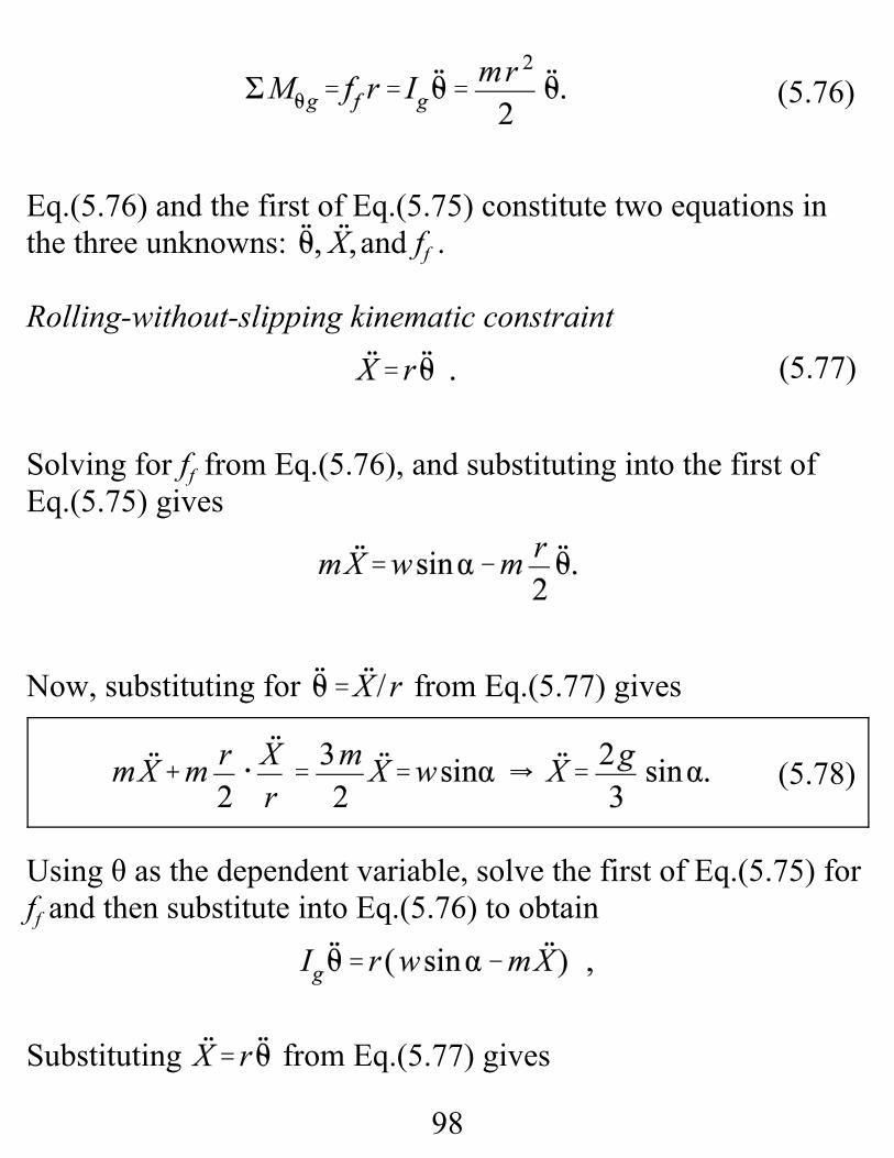
(5.76)
(5.77)
(5.78)
Eq.(5.76) and the first of Eq.(5.75) constitute two equations inthe three unknowns: and ff . Rolling-without-slipping kinematic constraint
Solving for ff from Eq.(5.76), and substituting into the first ofEq.(5.75) gives
Now, substituting for from Eq.(5.77) gives
Using θ as the dependent variable, solve the first of Eq.(5.75) forff and then substitute into Eq.(5.76) to obtain
Substituting from Eq.(5.77) gives
99
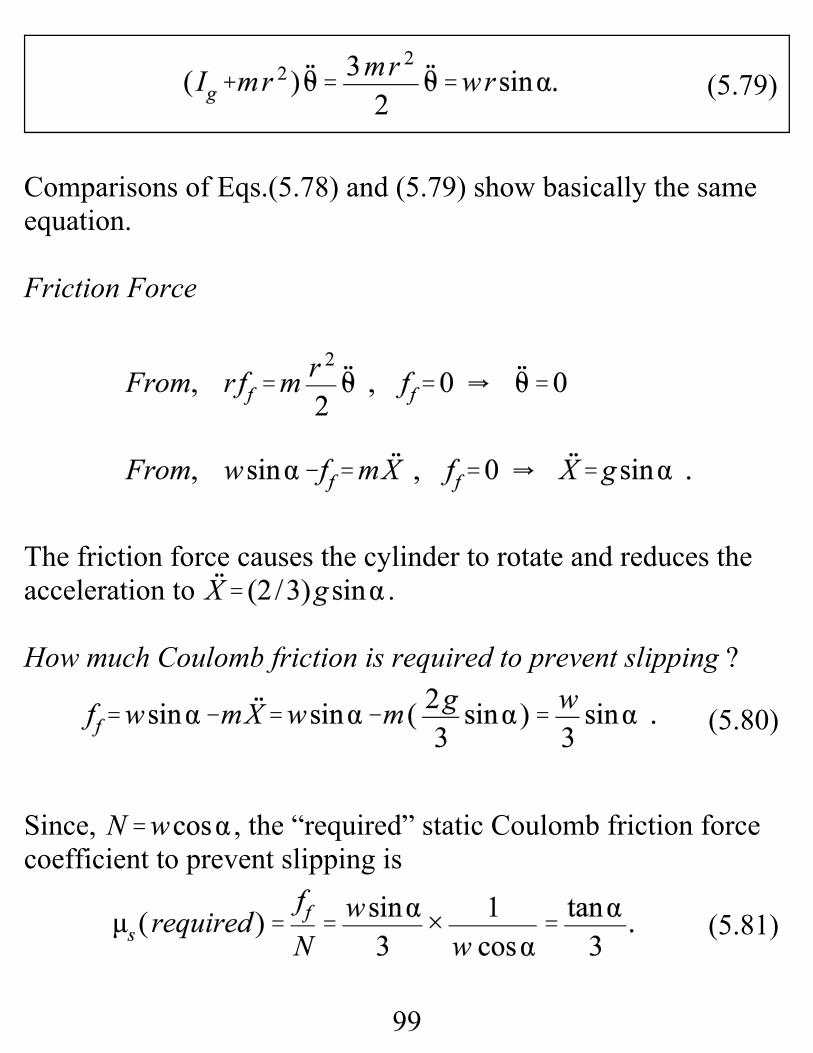
(5.79)
(5.80)
(5.81)
Comparisons of Eqs.(5.78) and (5.79) show basically the sameequation.
Friction Force
The friction force causes the cylinder to rotate and reduces theacceleration to .
How much Coulomb friction is required to prevent slipping ?
Since, , the “required” static Coulomb friction forcecoefficient to prevent slipping is
100
(i)
(ii)
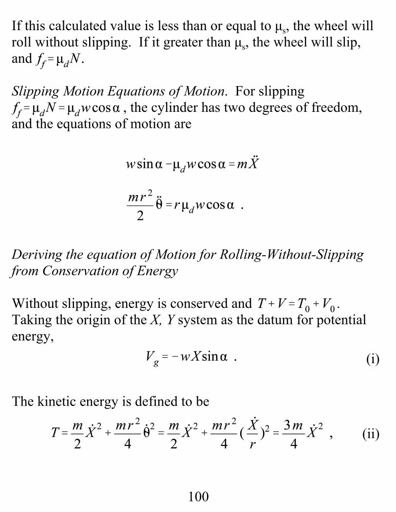
If this calculated value is less than or equal to μs, the wheel willroll without slipping. If it greater than μs, the wheel will slip,and
Slipping Motion Equations of Motion. For slipping, the cylinder has two degrees of freedom,
and the equations of motion are
Deriving the equation of Motion for Rolling-Without-Slippingfrom Conservation of Energy
Without slipping, energy is conserved and . Taking the origin of the X, Y system as the datum for potentialenergy,
The kinetic energy is defined to be

101
where the rolling without slipping relationship has beenused. Substituting from (i) and (ii) gives
Differentiating w.r.t. X
An Imbalanced Cylinder Rolling Down an Inclined Plane
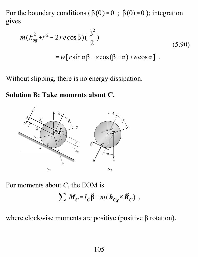
Figure 5.26 (a) Disk with its mass center displaced a distance efrom its geometrical center, rolling down an inclined plane, (b)Free-body diagram.
102
(5.84)
(5.85)
(5.83)
The disk’s mass center is located in the X, Y system by:
The rolling-without-slipping kinematic condition for figure5.26A is
Without slipping, the disk has two variables, X and β, but onlyone degree of freedom. The radius of gyration of the disk aboutpoint o is kog ; hence, .
Derive the governing differential equation of motion.
Solution A. Take moments about the mass center.
Applying for the disk’s mass center gives:
In reviewing these equations, note that .
Taking moments about the mass center, the moment equation is
103
(5.86)
(5.87)
Note that positive moments are in the +β , clockwise direction. Also, from the parallel-axis formula, .
Eqs.(5.84), ( 5.85) and (5.86) provide four equations in the sixunknowns: and ff .
Kinematics. Differentiating Eqs.(5.83) once with respect to timegives
Differentiating a second time and substituting for gives
which provides our final two equations.
The governing equation of motion is obtained by the followingsteps:
a. Substitute for from Eq.(5.87) into Eqs (5.85),obtaining
104
(5.89)
(5.88)
b. Substitute for N and ff into Eq.(5.86), obtaining
After a fair amount of algebra, the governing equation is
Note: .
This equation reduces to Eq.(5.79) if e = 0, and .
The energy-integral substitution, , convertsEq.(5.89) to
105
(5.90)
For the boundary conditions ( ); integrationgives
Without slipping, there is no energy dissipation.
Solution B: Take moments about C.
For moments about C, the EOM is
where clockwise moments are positive (positive β rotation).
106
(5.89)
Kinematics:
Inertia properties:
External moment about C due to weight
Plugging in the results gives (again)
This approach is obviously quicker.
107
(5.223)
(5.224)
Deriving the equation of Motion from Conservation of Energy
Applying , and using the origin of the X, Y systemfor the gravity potential-energy function gives
This example has three coordinates . To eliminateunwanted coordinates, we need the rolling-without-slippingcondition , plus the kinematic conditions,
Substituting into Eq.(5.223) gives
Differentiating with respect to β gives the DEQ. of motion
108
(5.204)
109
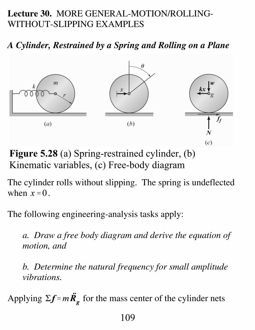
Figure 5.28 (a) Spring-restrained cylinder, (b)Kinematic variables, (c) Free-body diagram
Lecture 30. MORE GENERAL-MOTION/ROLLING-WITHOUT-SLIPPING EXAMPLES
A Cylinder, Restrained by a Spring and Rolling on a Plane
The cylinder rolls without slipping. The spring is undeflectedwhen .
The following engineering-analysis tasks apply:
a. Draw a free body diagram and derive the equation ofmotion, and
b. Determine the natural frequency for small amplitudevibrations.
Applying for the mass center of the cylinder nets
110
(5.117b)
(5.117c)
(5.118)
(5.117a)
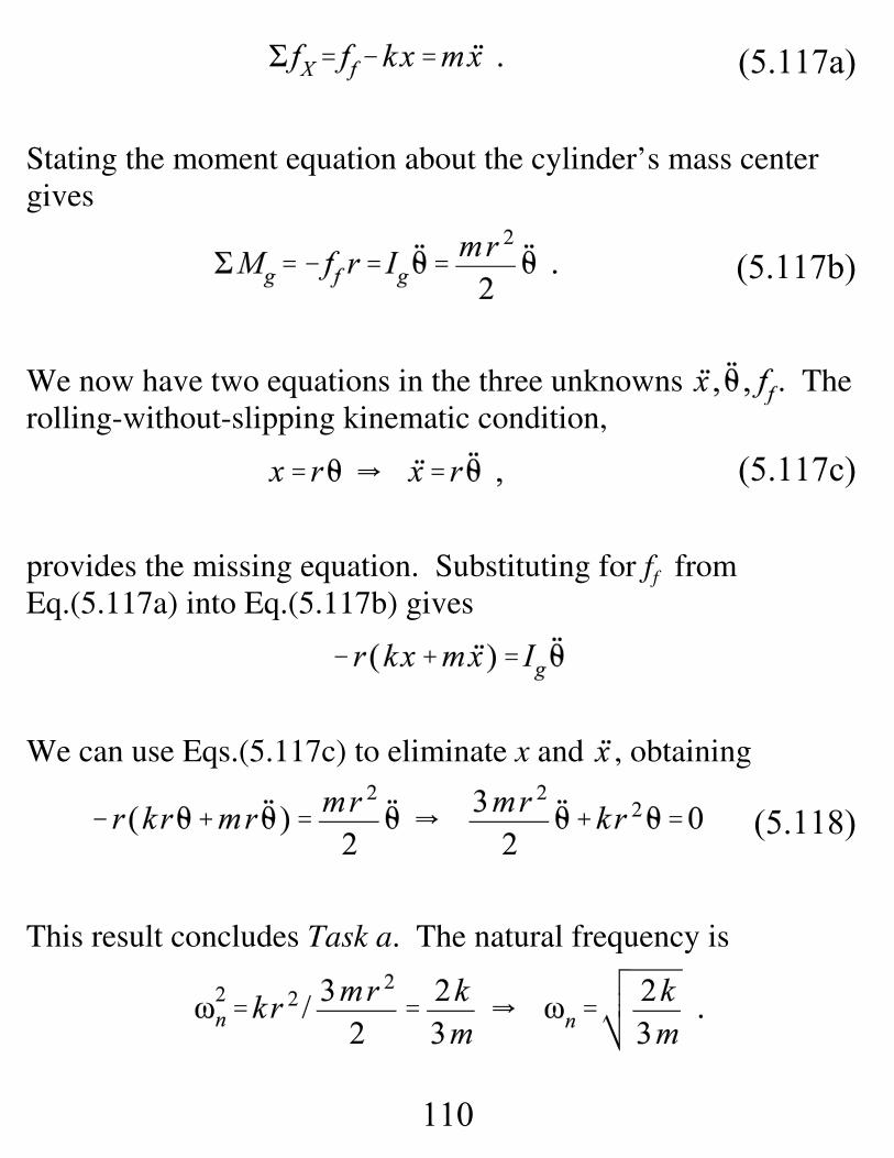
Stating the moment equation about the cylinder’s mass centergives
We now have two equations in the three unknowns . Therolling-without-slipping kinematic condition,
provides the missing equation. Substituting for ff fromEq.(5.117a) into Eq.(5.117b) gives
We can use Eqs.(5.117c) to eliminate x and , obtaining
This result concludes Task a. The natural frequency is
111
This result concludes Task b. The cylinder inertia has caused asubstantial reduction in the natural frequency as compared to asimple spring-mass system that would yield .
Deriving The Equation of Motion From Conservation ofEnergy
Conservation of energy implies,
Substituting the rolling-without-slipping kinematic conditions, gives
where from Appendix C, . Differentiating withrespect to θ gives the equation of motion
where .
112
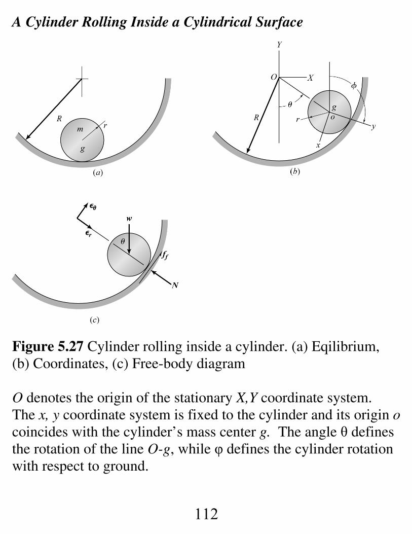
A Cylinder Rolling Inside a Cylindrical Surface
Figure 5.27 Cylinder rolling inside a cylinder. (a) Eqilibrium,(b) Coordinates, (c) Free-body diagram
O denotes the origin of the stationary X,Y coordinate system. The x, y coordinate system is fixed to the cylinder and its origin ocoincides with the cylinder’s mass center g. The angle θ definesthe rotation of the line O-g, while φ defines the cylinder rotationwith respect to ground.
113
(5.119a)
(5.119b)
(5.120)
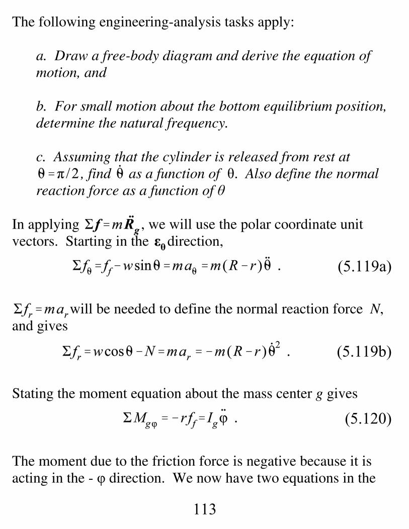
The following engineering-analysis tasks apply:
a. Draw a free-body diagram and derive the equation ofmotion, and
b. For small motion about the bottom equilibrium position,determine the natural frequency.
c. Assuming that the cylinder is released from rest at, find as a function of θ. Also define the normal
reaction force as a function of θ
In applying , we will use the polar coordinate unitvectors. Starting in the direction,
will be needed to define the normal reaction force N,and gives
Stating the moment equation about the mass center g gives
The moment due to the friction force is negative because it isacting in the - φ direction. We now have two equations in the
114
(5.122)
(5.121)
three unknowns . From Eq.(4.14a), the requiredkinematic constraint equation between and is
Substituting for ff from Eq.(5.119a) into Eq.(5.120) gives
Now substituting for from Eq.(5.121) gives
For small θ, , the linearized equation of motion is
and the natural frequency is .
The solution for as a function of θ can be developed fromEq.(5.122) via the energy-integral substitution as
115
(5.124)
(5.123)
Integration from the initial condition yields
and
provides the requested solution. Substituting for intoEq.(5.119b) defines N as
and (formally) meets the requirements of Task c.
However, note from Eq.(5.124) that at ; hence,from our initial condition, the wheel will slip initially until N becomes large enough for the Coulomb friction force toprevent slipping.
1 Note that the friction force would have adifferent sign if the cylinder were released fromrest at
116
(5.125)
With slipping, the appropriate model as provided fromEqs.(5.119a-120) and is:
Eliminating gives the two coupled nonlinear equations ofmotion:
These equations apply during slipping, provided that thedirection of the friction force in figure does not change1. Withslipping, the cylinder has two degrees of freedom, θ and φ. Notefrom Eqs.(5.125) that initially, at , and . As thecylinder rolls down the surface, and increase in magnitudebut are negative. The friction force acts to slow down themagnitude increase in and accelerate the magnitude increase in
117
. When the kinematic condition is met, slippingstops, Eqs.(5.125) become invalid, and Eq.(5.122) applies.
Deriving the Equation of Motion From Conservation ofEnergy
With O, the origin of the X, Y system as the gravity potentialenergy datum, implies
Substituting and gives
or
Differentiating w.r.t. θ gives
118
where .
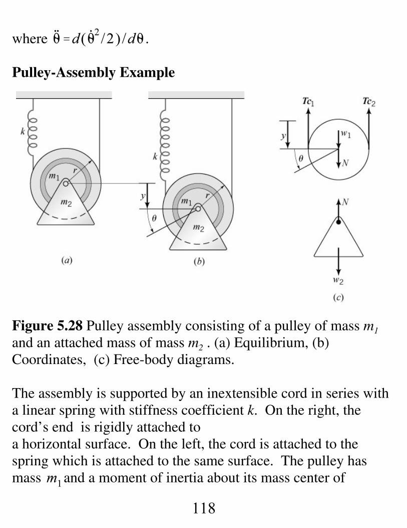
Pulley-Assembly Example
Figure 5.28 Pulley assembly consisting of a pulley of mass m1
and an attached mass of mass m2 . (a) Equilibrium, (b)Coordinates, (c) Free-body diagrams.
The assembly is supported by an inextensible cord in series witha linear spring with stiffness coefficient k. On the right, thecord’s end is rigidly attached to a horizontal surface. On the left, the cord is attached to thespring which is attached to the same surface. The pulley hasmass and a moment of inertia about its mass center of
119
(5.126)
(5.127a)
. The cord does not slip on the pulley.
The engineering analysis tasks are:
a. Draw free-body diagrams and derive the equation ofmotion.
b. Determine the natural frequency
The statement that the “cord does not slip on the pulley”introduces the rolling-without-slipping condition. The pulleycan be visualized as rolling without slipping on the verticalsurface defined by the right-hand-side cord line. The ycoordinate locates the change in position of the pulley, and θdefines the pulley’s rotation angle. The spring is assumed to beundeflected when . The y and θ coordinates are related viathe rolling-without-slipping kinematic condition,
Figure 5.30B provides the appropriate free-body diagrams withthe pulley and the lower assembly separated. The reaction forceN acts between the two masses at the pivot connection point. The moment equation about the pulley’s mass center is
120
(5.127b)
(5.128)
Note that and are different. They must be different toinduce the pulley’s angular acceleration. The pulley’s masscenter and the lower assembly have the same acceleration; hencetheir equations of motion are:
Adding these last equations eliminates N netting
Eqs.(5.126), (5.127), and (5.128) provide three equations for thefour unknowns .
We need another kinematic constraint equation. Pulling thepulley down a distance y will pull the cord end attached to thespring down a distance 2y. Hence, the cord tension isdefined by . Substituting this result andsubstituting and gives
Eliminating by multiplying the second of these equations by
121
r and adding the result to the first gives
and the equation of motion is
The natural frequency is defined by
This example is “tricky” in that the rolling-without-slippingconstraint and the second pulley constraint to define the springdeflection, , are not immediately obvious.
122
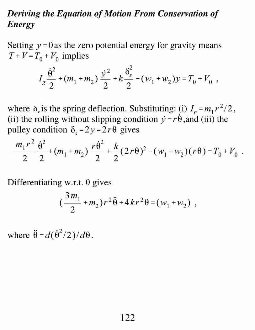
Deriving the Equation of Motion From Conservation ofEnergy
Setting as the zero potential energy for gravity means implies
where is the spring deflection. Substituting: (i) ,(ii) the rolling without slipping condition ,and (iii) thepulley condition gives
Differentiating w.r.t. θ gives
where .
124
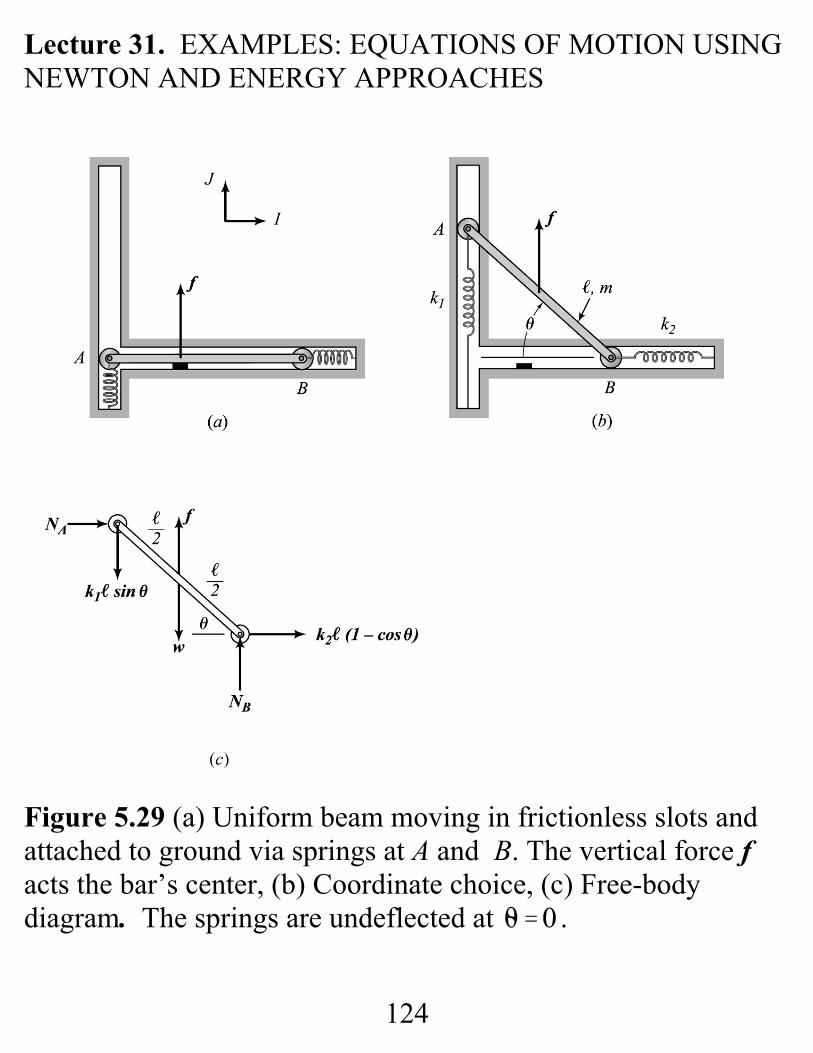
Lecture 31. EXAMPLES: EQUATIONS OF MOTION USINGNEWTON AND ENERGY APPROACHES
Figure 5.29 (a) Uniform beam moving in frictionless slots andattached to ground via springs at A and B. The vertical force facts the bar’s center, (b) Coordinate choice, (c) Free-bodydiagram. The springs are undeflected at .
125
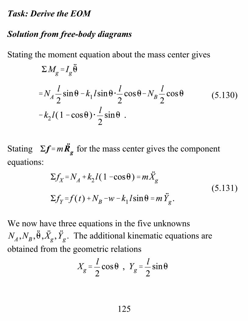
(5.130)
(5.131)
Task: Derive the EOM
Solution from free-body diagrams
Stating the moment equation about the mass center gives
Stating for the mass center gives the componentequations:
We now have three equations in the five unknowns. The additional kinematic equations are
obtained from the geometric relations
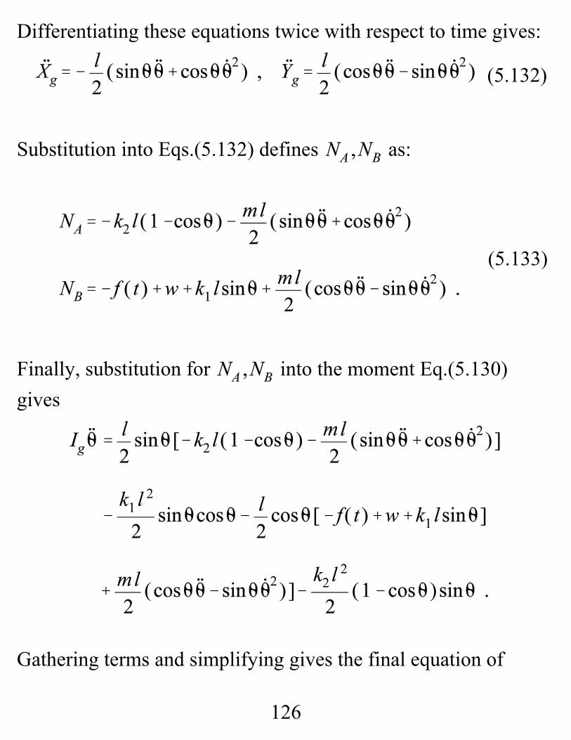
126
(5.132)
(5.133)
Differentiating these equations twice with respect to time gives:
Substitution into Eqs.(5.132) defines as:
Finally, substitution for into the moment Eq.(5.130)gives
Gathering terms and simplifying gives the final equation of
127
(5.134)
motion
Developments from Work EnergyThe absence of energy-dissipation forces makes this example anideal application for the work-energy equation
.
The following engineering analysis tasks apply :
a. If the bar starts from rest at , and , determineits angular velocity when .
b. Derive the equation of motion.
First find Figure 5.29c illustrates the force vector , located in the fixed X, Y system by the vector
. The differential work done by the forceacting through a differential change in position is
128
where is the generalized force associated with θ. The masscenter of the body is also located by r1 ; hence,
, and the kinetic energy is
Establishing the gravity potential-energy datum in the center ofthe lower guide slot yields . The spring potentialenergy function is defined by
Plugging all of these results into the work-energy equation gives
129
(5.227)
(5.228)
where the initial potential and kinetic energy are zero. EvaluatingEq.(5.227) for and gives
and concludes Task a. The equation of motion is obtained by differentiating
Eq.(5.227) with respect to θ, obtaining,
where . This step concludes Task b. Note the generalized force term on the right-hand side
of Eq.(5.228). Changing the external-force definition modifiesonly this term, leaving the left hand side of the equation
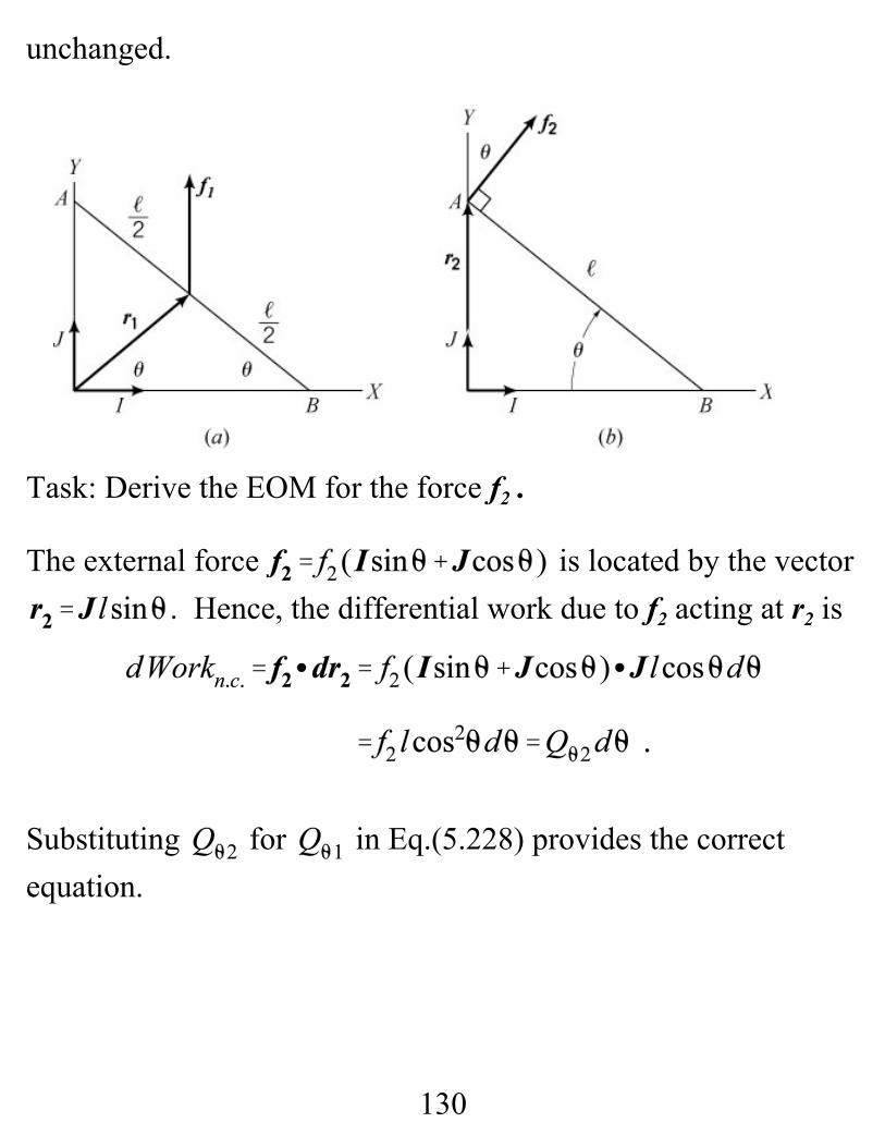
130
unchanged.
Task: Derive the EOM for the force f2 .
The external force is located by the vector. Hence, the differential work due to f2 acting at r2 is
Substituting for in Eq.(5.228) provides the correctequation.
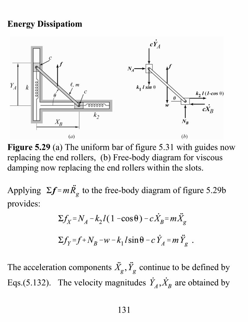
131
Energy Dissipatiom
Figure 5.29 (a) The uniform bar of figure 5.31 with guides nowreplacing the end rollers, (b) Free-body diagram for viscousdamping now replacing the end rollers within the slots.
Applying to the free-body diagram of figure 5.29bprovides:
The acceleration components continue to be defined by
Eqs.(5.132). The velocity magnitudes are obtained by
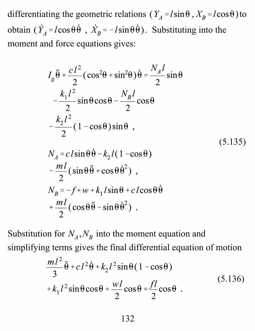
132
(5.136)
(5.135)
differentiating the geometric relations to
obtain . Substituting into themoment and force equations gives:
Substitution for into the moment equation andsimplifying terms gives the final differential equation of motion

133
The damping term on the left is the only addition to the priormoment Eq.(5.134).
Developing the equations of motion from work energy startsfrom
where
Hence,
Plugging this result into Eq.(5.128) gives the equation ofmotion. Accounting for energy dissipation due to viscousdamping is easy since the damping force can be stated directly. Things are less pleasant with Coulomb damping.
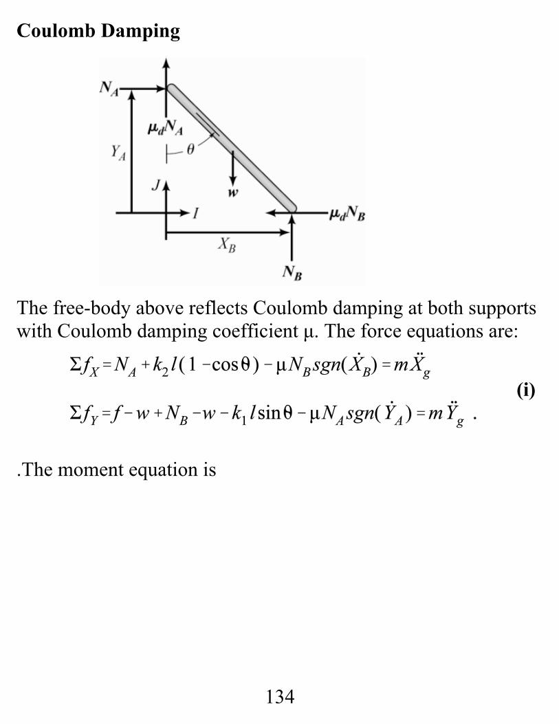
134
(i)
Coulomb Damping
The free-body above reflects Coulomb damping at both supportswith Coulomb damping coefficient μ. The force equations are:
.The moment equation is
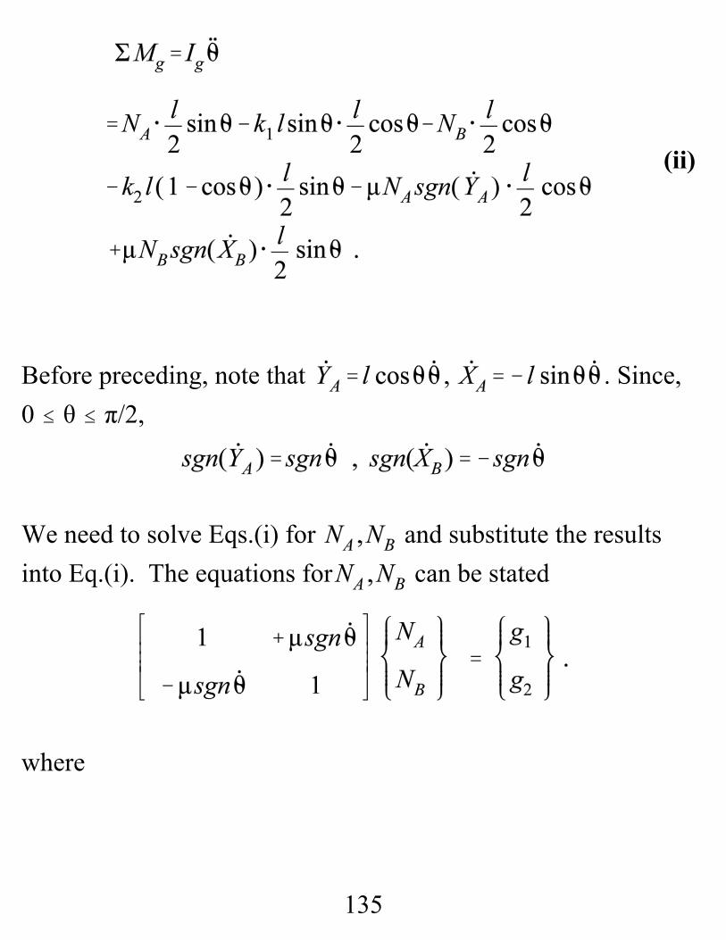
135
(ii)
Before preceding, note that , . Since, 0 # θ # π/2,
We need to solve Eqs.(i) for and substitute the resultsinto Eq.(i). The equations for can be stated
where
136
(iii)
Solving for gives
Substituting these result into Eq.(i) gives the equations ofmotion.
Trying to do this with work-energy starts reasonably. Thedifferential work is
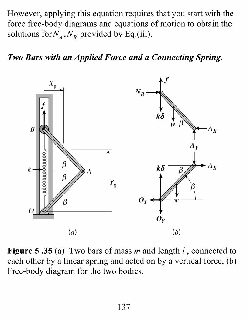
137
However, applying this equation requires that you start with theforce free-body diagrams and equations of motion to obtain thesolutions for provided by Eq.(iii).
Two Bars with an Applied Force and a Connecting Spring.
Figure 5 .35 (a) Two bars of mass m and length l , connected toeach other by a linear spring and acted on by a vertical force, (b)Free-body diagram for the two bodies.
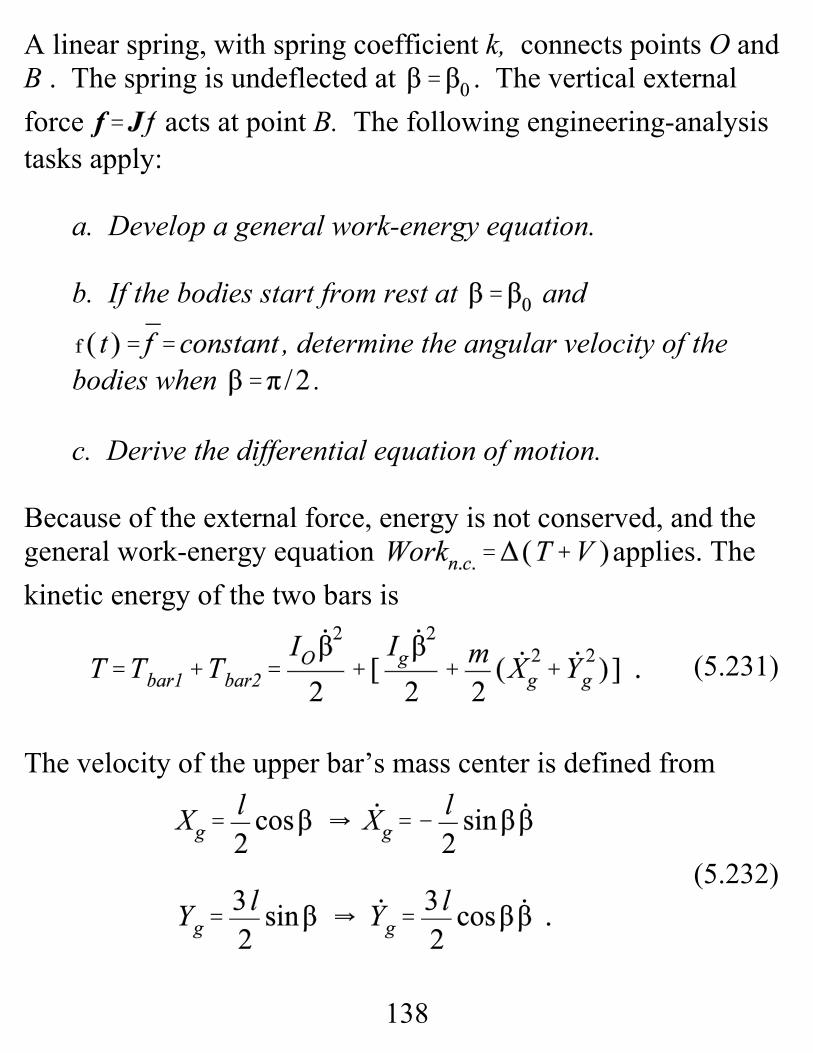
138
(5.232)
(5.231)
A linear spring, with spring coefficient k, connects points O andB . The spring is undeflected at . The vertical externalforce acts at point B. The following engineering-analysistasks apply:
a. Develop a general work-energy equation.
b. If the bodies start from rest at and
, determine the angular velocity of thebodies when .
c. Derive the differential equation of motion.
Because of the external force, energy is not conserved, and thegeneral work-energy equation applies. Thekinetic energy of the two bars is
The velocity of the upper bar’s mass center is defined from
139
Substituting these results plus ( ) intoEq.(5.231) gives
For the gravity potential-energy datum through O, themechanical potential energy is
The differential work due to the external force is
Substituting into the work-energy equation gives
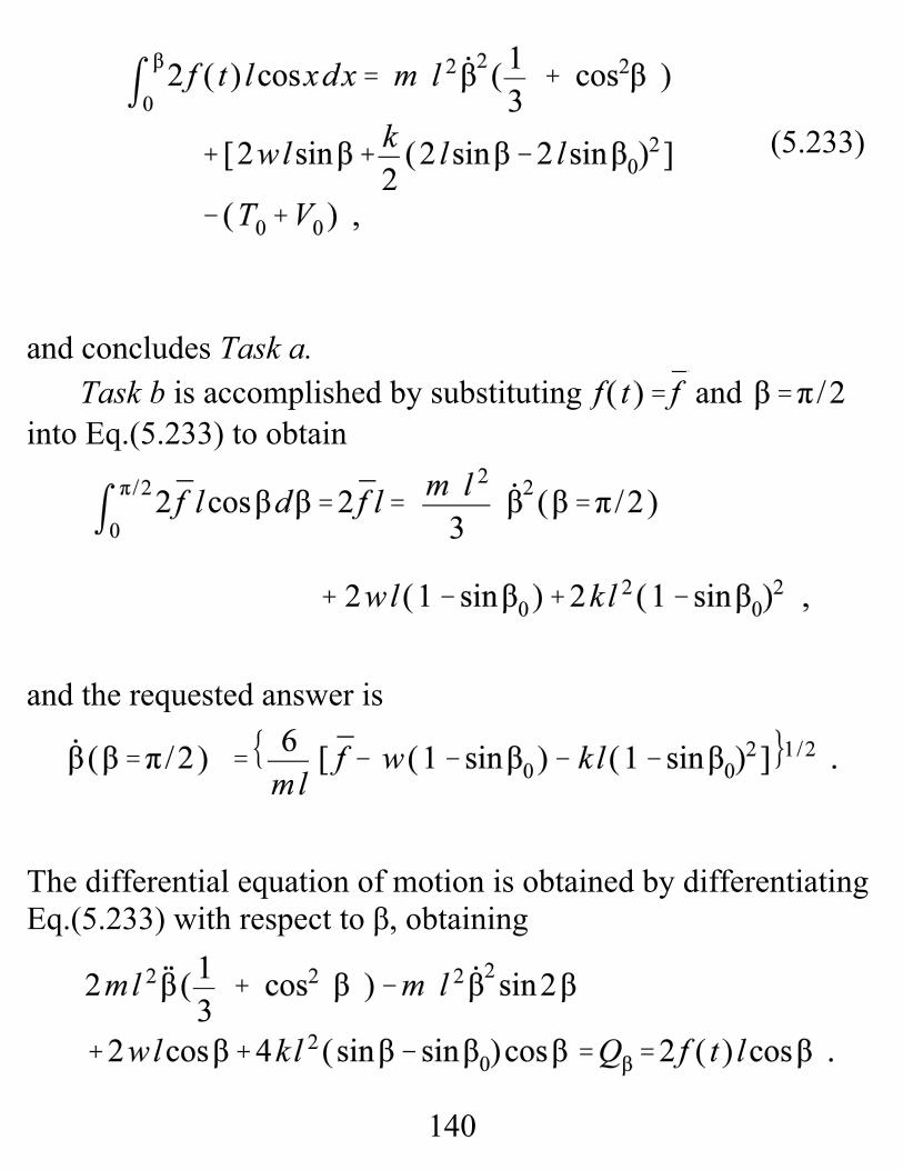
140
(5.233)
and concludes Task a. Task b is accomplished by substituting and
into Eq.(5.233) to obtain
and the requested answer is
The differential equation of motion is obtained by differentiatingEq.(5.233) with respect to β, obtaining
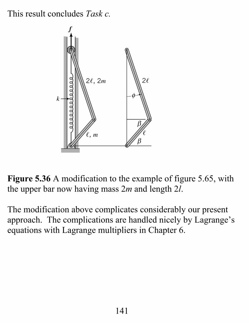
141
This result concludes Task c.
Figure 5.36 A modification to the example of figure 5.65, withthe upper bar now having mass 2m and length 2l.
The modification above complicates considerably our presentapproach. The complications are handled nicely by Lagrange’sequations with Lagrange multipliers in Chapter 6.
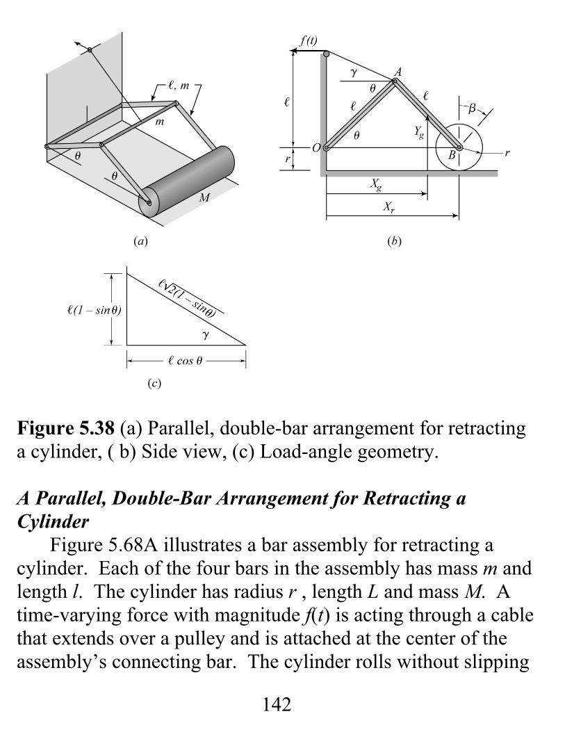
142
Figure 5.38 (a) Parallel, double-bar arrangement for retractinga cylinder, ( b) Side view, (c) Load-angle geometry.
A Parallel, Double-Bar Arrangement for Retracting aCylinder
Figure 5.68A illustrates a bar assembly for retracting acylinder. Each of the four bars in the assembly has mass m andlength l. The cylinder has radius r , length L and mass M. Atime-varying force with magnitude f(t) is acting through a cablethat extends over a pulley and is attached at the center of theassembly’s connecting bar. The cylinder rolls without slipping
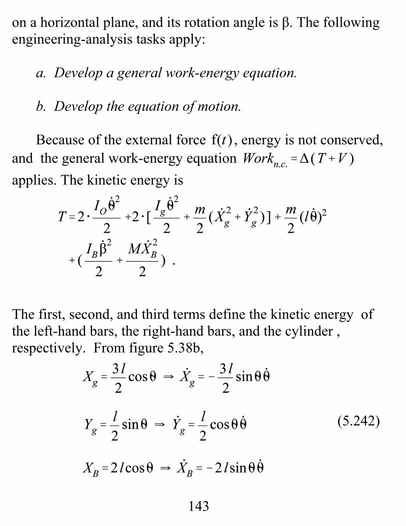
143
(5.242)
on a horizontal plane, and its rotation angle is β. The followingengineering-analysis tasks apply:
a. Develop a general work-energy equation.
b. Develop the equation of motion.
Because of the external force , energy is not conserved, and the general work-energy equation applies. The kinetic energy is
The first, second, and third terms define the kinetic energy ofthe left-hand bars, the right-hand bars, and the cylinder ,respectively. From figure 5.38b,
144
(5.243)
The rolling-without-slipping condition is
Substituting the kinematic results from Eqs.(5.242 and 5.243)plus the moment of inertia results ( , ,and ) from Appendix C into T gives
Defining the datum for gravity potential energy by a planethrough O and B yields the potential-energy function
Working out the differential-work function due to the forceacting at A is a little complicated for this example. The
145
(5.244)
force acts at the angle γ from the horizontal. Figure 5.38cshows the right triangle defining γ and provides:
Hence, the force vector is . The forceacts at the position , and the differentialnonconservative work is
Substituting for T , V , and into the work-energyequation gives
and concludes Task a.
146
Differentiating Eq.(5.244) with respect to θ gives thedifferential equation of motion
where , and concludes Task c.


![Download [5.17 MB]](https://img.pdfslide.net/doc/110x75/586768a71a28ab52568b4d21/download-517-mb.jpg)

