Embed Size (px)
Citation preview

Chapter 18 REV. 6/08-10-0718-i
Lancair International Inc., Represented by Neico Aviation Inc., Copyright © 2000 , Redmond, OR 97756
REVISION LIST
CHAPTER 24: MISCELLANEOUS SYSTEMS
The following list of revisions will allow you to update the Legacy construction manual chapter listed above.
Under the “Action” column, “R&R” directs you to remove and replace the pages affected by the revision. “Add” directs you to
insert the pages shows and “R” to remove the pages.
PAGE(S) AFFECTED REVISION # & DATE ACTION DESCRIPTION
24-1 through 24-2 0/02-15-02 None Current revision is correct
24-3 1/09-18-02 R&R Corrected fig. 24:A:2
24-4 through 24-16 0/02-15-02 None Current revision is correct
24-1 3/12-15-04 R&R Updated table of contents with page numbers
and modified parts list.
24-2 3/12-15-04 R&R Updated pitot tube part nbrs.
24-4 3/12-15-04 R&R Updated part nbrs.
24-6 3/12-15-04 R&R Updated part nbrs.
24-1, 24-3, 24-14 6/08-10-07 R&R Adjustments to static port and added part
numbers.
Chapter 2424-i
MISCELLANEOUS SYSTEMS
Chapter 24 REV. 0/02-15-02
MISCELLANEOUS SYSTEMS24-1
Lancair International Inc., Represented by Neico Aviation Inc., Copyright © 2000 , Redmond, OR 97756
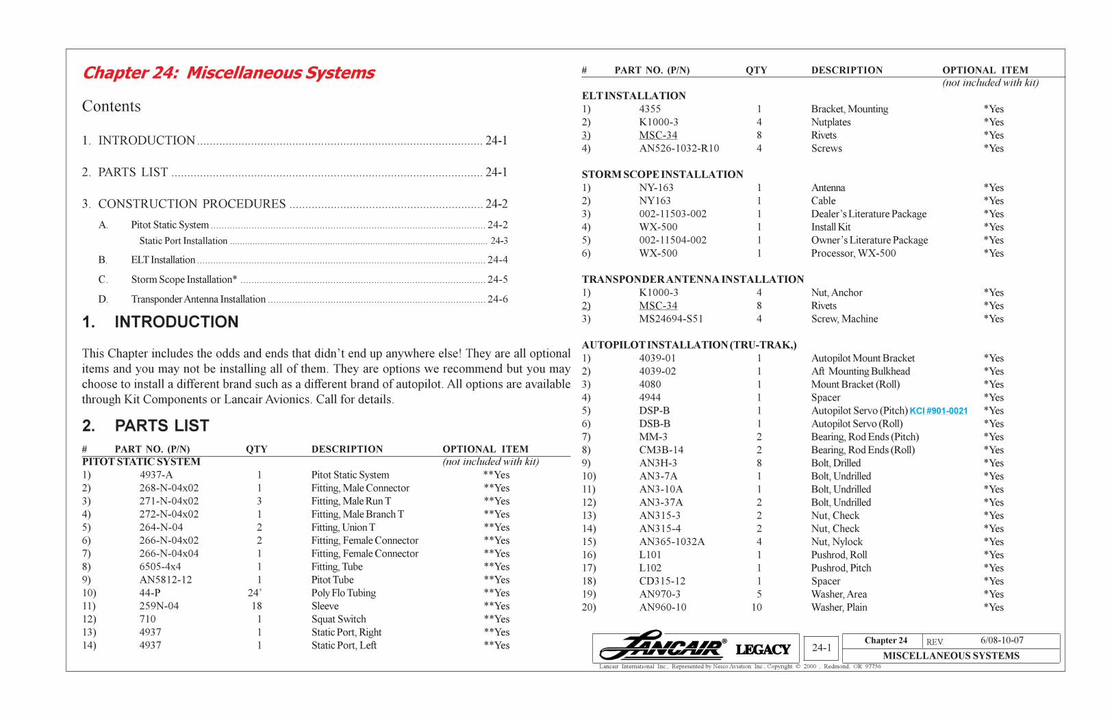
1. INTRODUCTION
This Chapter includes the odds and ends that didn’t end up anywhere else! They are all optional
items and you may not be installing all of them. They are options we recommend but you may
choose to install a different brand such as a different brand of autopilot. All options are available
through Kit Components or Lancair Avionics. Call for details.
2. PARTS LIST
# PART NO. (P/N) QTY DESCRIPTION OPTIONAL ITEM
PITOT STATIC SYSTEM (not included with kit)
1) 4937-A 1 Pitot Static System **Yes
2) 268-N-04x02 1 Fitting, Male Connector **Yes
3) 271-N-04x02 3 Fitting, Male Run T **Yes
4) 272-N-04x02 1 Fitting, Male Branch T **Yes
5) 264-N-04 2 Fitting, Union T **Yes
6) 266-N-04x02 2 Fitting, Female Connector **Yes
7) 266-N-04x04 1 Fitting, Female Connector **Yes
8) 6505-4x4 1 Fitting, Tube **Yes
9) AN5812-12 1 Pitot Tube **Yes
10) 44-P 24’ Poly Flo Tubing **Yes
11) 259N-04 18 Sleeve **Yes
12) 710 1 Squat Switch **Yes
13) 4937 1 Static Port, Right **Yes
14) 4937 1 Static Port, Left **Yes
Chapter 24: Miscellaneous Systems # PART NO. (P/N) QTY DESCRIPTION OPTIONAL ITEM
(not included with kit)
ELT INSTALLATION
1) 4355 1 Bracket, Mounting *Yes
2) K1000-3 4 Nutplates *Yes
3) MSC-34 8 Rivets *Yes
4) AN526-1032-R10 4 Screws *Yes
STORM SCOPE INSTALLATION
1) NY-163 1 Antenna *Yes
2) NY163 1 Cable *Yes
3) 002-11503-002 1 Dealer’s Literature Package *Yes
4) WX-500 1 Install Kit *Yes
5) 002-11504-002 1 Owner’s Literature Package *Yes
6) WX-500 1 Processor, WX-500 *Yes
TRANSPONDER ANTENNA INSTALLATION
1) K1000-3 4 Nut, Anchor *Yes
2) MSC-34 8 Rivets *Yes
3) MS24694-S51 4 Screw, Machine *Yes
AUTOPILOT INSTALLATION (TRU-TRAK,)
1) 4039-01 1 Autopilot Mount Bracket *Yes
2) 4039-02 1 Aft Mounting Bulkhead *Yes
3) 4080 1 Mount Bracket (Roll) *Yes
4) 4944 1 Spacer *Yes
5) DSP-B 1 Autopilot Servo (Pitch) KCI #901-0021 *Yes
6) DSB-B 1 Autopilot Servo (Roll) *Yes
7) MM-3 2 Bearing, Rod Ends (Pitch) *Yes
8) CM3B-14 2 Bearing, Rod Ends (Roll) *Yes
9) AN3H-3 8 Bolt, Drilled *Yes
10) AN3-7A 1 Bolt, Undrilled *Yes
11) AN3-10A 1 Bolt, Undrilled *Yes
12) AN3-37A 2 Bolt, Undrilled *Yes
13) AN315-3 2 Nut, Check *Yes
14) AN315-4 2 Nut, Check *Yes
15) AN365-1032A 4 Nut, Nylock *Yes
16) L101 1 Pushrod, Roll *Yes
17) L102 1 Pushrod, Pitch *Yes
18) CD315-12 1 Spacer *Yes
19) AN970-3 5 Washer, Area *Yes
20) AN960-10 10 Washer, Plain *Yes
Contents
1. INTRODUCTION.......................................................................................... 24-1
2. PARTS LIST .................................................................................................. 24-1
3. CONSTRUCTION PROCEDURES ............................................................. 24-2
A. Pitot Static System ..................................................................................................... 24-2
Static Port Installation ....................................................................................................... 24-3
B. ELT Installation .......................................................................................................... 24-4
C. Storm Scope Installation* .......................................................................................... 24-5
D. Transponder Antenna Installation ................................................................................ 24-6
6/08-10-07
Chapter 24 REV. 0/02-15-02
MISCELLANEOUS SYSTEMS24-2
Lancair International Inc., Represented by Neico Aviation Inc., Copyright © 2000 , Redmond, OR 97756
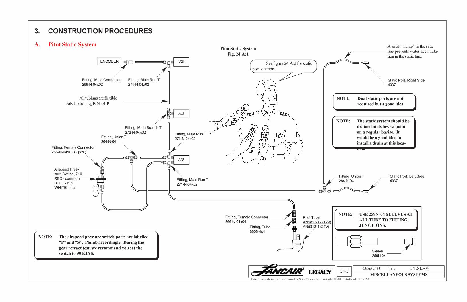
3. CONSTRUCTION PROCEDURES
A. Pitot Static SystemPitot Static System
Fig. 24:A:1
Fitting, Female Connector
266-N-04x04
Fitting, Tube
6505-4x4
NOTE: The airspeed pressure switch ports are labelled
“P” and “S”. Plumb accordingly. During the
gear retract test, we recommend you set the
switch to 90 KIAS.
See figure 24:A:2 for static
port location.
Static Port, Right Side
4937
Static Port, Left Side
4937
NOTE: Dual static ports are not
required but a good idea.
VSI
ALT
A/S
ENCODER
Pitot Tube
AN5812-12 (12V)
AN5812-1 (24V)
Fitting, Male Run T
271-N-04x02
Fitting, Male Run T
271-N-04x02Fitting, Union T
264-N-04
Fitting, Female Connector
266-N-04x02 (2 pcs.)
Airspeed Pres-
sure Switch, 710
RED - common
BLUE - n.o.
WHITE - n.c.
Fitting, Male Branch T
272-N-04x02
All tubings are flexible
poly flo tubing, P/N 44-P.
Fitting, Male Run T
271-N-04x02
Fitting, Male Connector
268-N-04x02
Fitting, Union T
264-N-04
A small “hump” in the satic
line prevents water accumula-
tion in the static line.
NOTE: The static system should be
drained at its lowest point
on a regular basise. It
would be a good idea to
install a drain at this loca-
tion.
NOTE: USE 259N-04 SLEEVES AT
ALL TUBE TO FITTING
JUNCTIONS.
Sleeve
259N-04
3/12-15-04
Chapter 24 REV. 0/02-15-02
MISCELLANEOUS SYSTEMS24-3
Lancair International Inc., Represented by Neico Aviation Inc., Copyright © 2000 , Redmond, OR 97756
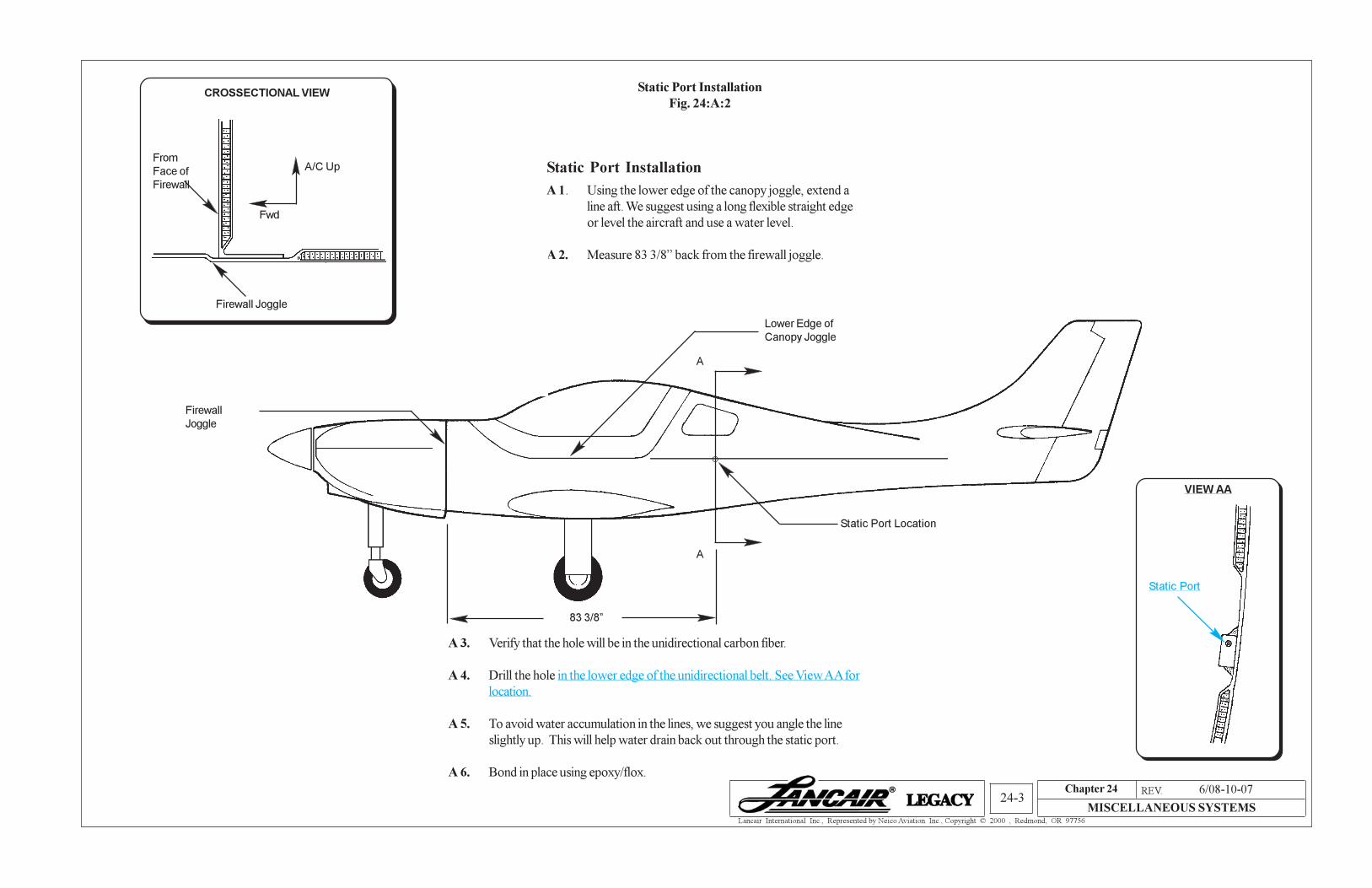
Static Port Installation
Fig. 24:A:2
A 3. Verify that the hole will be in the unidirectional carbon fiber.
A 4. Drill the hole in the lower edge of the unidirectional belt. See View AA for
location.
A 5. To avoid water accumulation in the lines, we suggest you angle the line
slightly up. This will help water drain back out through the static port.
A 6. Bond in place using epoxy/flox.
Static Port Installation
A 1. Using the lower edge of the canopy joggle, extend a
line aft. We suggest using a long flexible straight edge
or level the aircraft and use a water level.
A 2. Measure 83 3/8” back from the firewall joggle.
Static Port Location
Firewall
Joggle
Lower Edge of
Canopy Joggle
A
A
83 3/8”
CROSSECTIONAL VIEW
From
Face of
Firewall
Firewall Joggle
A/C Up
Fwd
VIEW AA
Static Port
6/08-10-07
Chapter 24 REV. 0/02-15-02
MISCELLANEOUS SYSTEMS24-4
Lancair International Inc., Represented by Neico Aviation Inc., Copyright © 2000 , Redmond, OR 97756
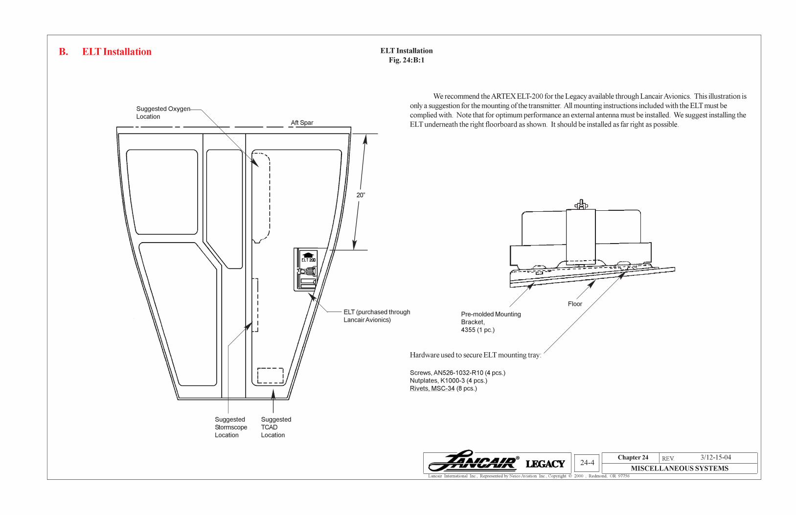
B. ELT Installation
We recommend the ARTEX ELT-200 for the Legacy available through Lancair Avionics. This illustration is
only a suggestion for the mounting of the transmitter. All mounting instructions included with the ELT must be
complied with. Note that for optimum performance an external antenna must be installed. We suggest installing the
ELT underneath the right floorboard as shown. It should be installed as far right as possible.
ELT Installation
Fig. 24:B:1
Suggested Oxygen
Location
Suggested
Stormscope
Location
Suggested
TCAD
Location
Pre-molded Mounting
Bracket,
4355 (1 pc.)
Hardware used to secure ELT mounting tray:
Screws, AN526-1032-R10 (4 pcs.)
Nutplates, K1000-3 (4 pcs.)
Rivets, MSC-34 (8 pcs.)
Aft Spar
ELT (purchased through
Lancair Avionics)
20”
Floor
3/12-15-04
Chapter 24 REV. 0/02-15-02
MISCELLANEOUS SYSTEMS24-5
Lancair International Inc., Represented by Neico Aviation Inc., Copyright © 2000 , Redmond, OR 97756
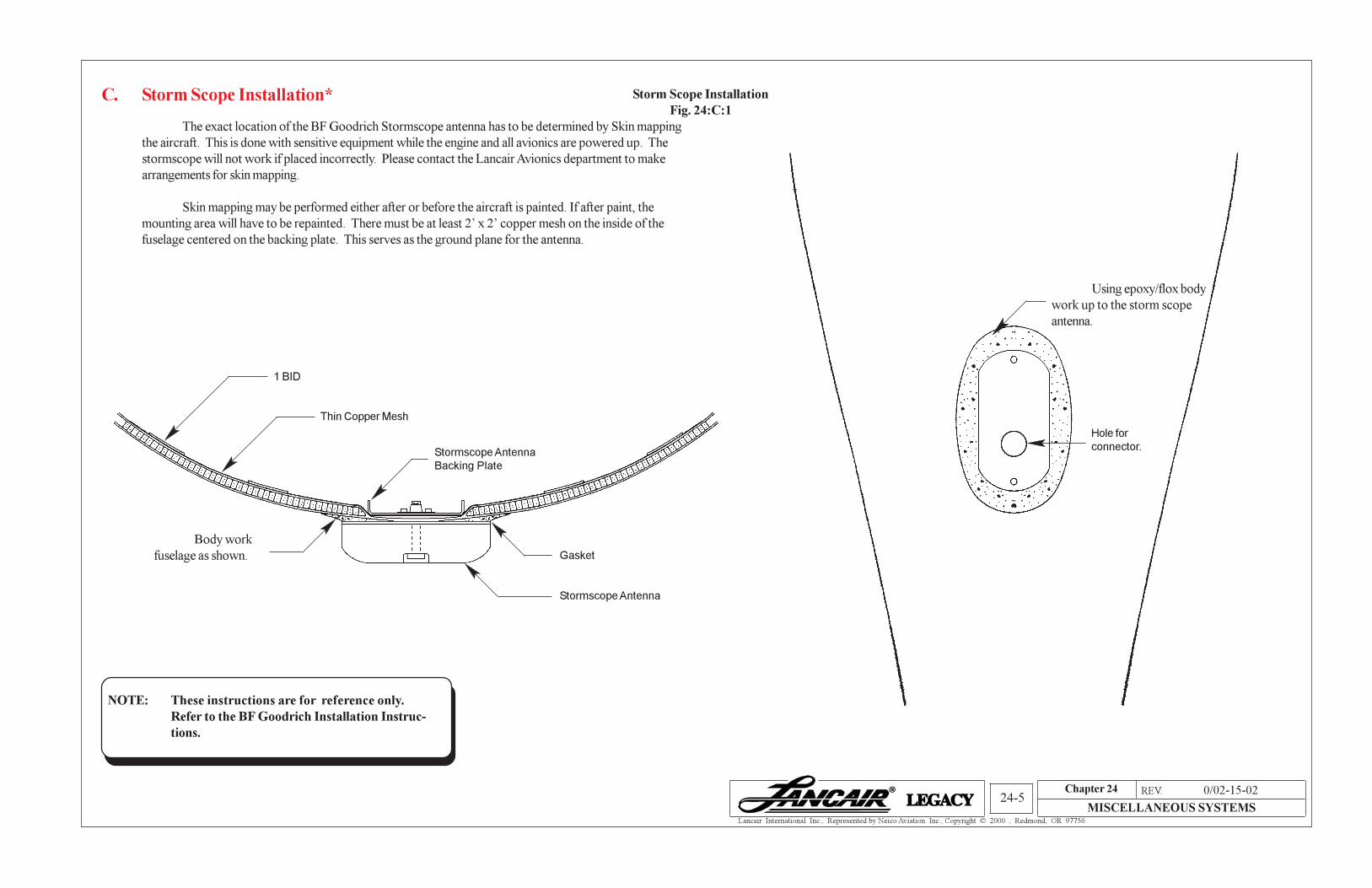
C. Storm Scope Installation*
The exact location of the BF Goodrich Stormscope antenna has to be determined by Skin mapping
the aircraft. This is done with sensitive equipment while the engine and all avionics are powered up. The
stormscope will not work if placed incorrectly. Please contact the Lancair Avionics department to make
arrangements for skin mapping.
Skin mapping may be performed either after or before the aircraft is painted. If after paint, the
mounting area will have to be repainted. There must be at least 2’ x 2’ copper mesh on the inside of the
fuselage centered on the backing plate. This serves as the ground plane for the antenna.
Storm Scope Installation
Fig. 24:C:1
1 BID
Thin Copper Mesh
Stormscope Antenna
Backing Plate
Body work
fuselage as shown.
Using epoxy/flox body
work up to the storm scope
antenna.
Hole for
connector.
Gasket
Stormscope Antenna
NOTE: These instructions are for reference only.
Refer to the BF Goodrich Installation Instruc-
tions.
Chapter 24 REV. 0/02-15-02
MISCELLANEOUS SYSTEMS24-6
Lancair International Inc., Represented by Neico Aviation Inc., Copyright © 2000 , Redmond, OR 97756
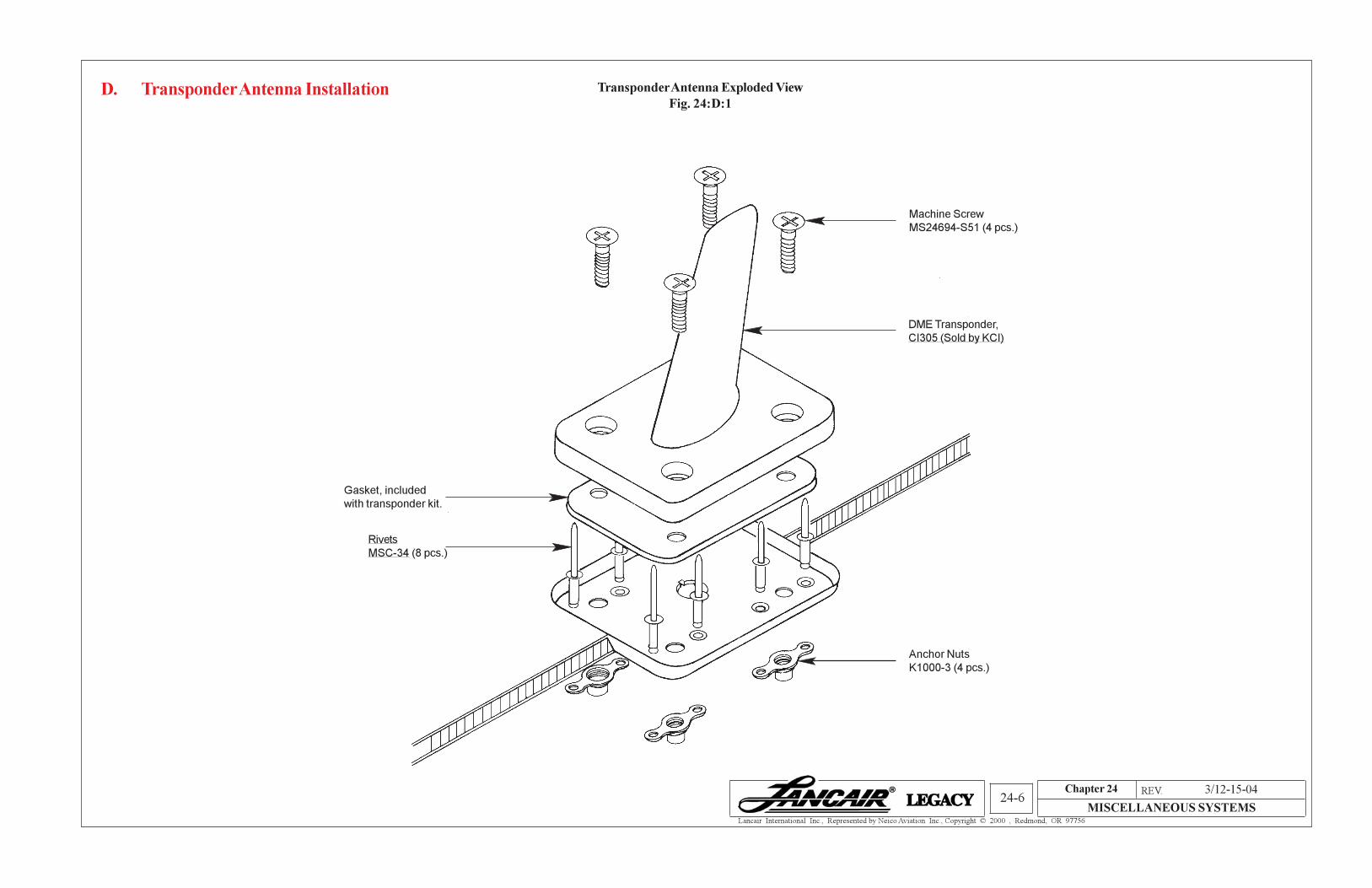
D. Transponder Antenna Installation Transponder Antenna Exploded View
Fig. 24:D:1
DME Transponder,
CI305 (Sold by KCI)
Machine Screw
MS24694-S51 (4 pcs.)
Rivets
MSC-34 (8 pcs.)
Anchor Nuts
K1000-3 (4 pcs.)
Gasket, included
with transponder kit.
3/12-15-04
Chapter 24 REV. 0/02-15-02
MISCELLANEOUS SYSTEMS24-7
Lancair International Inc., Represented by Neico Aviation Inc., Copyright © 2000 , Redmond, OR 97756
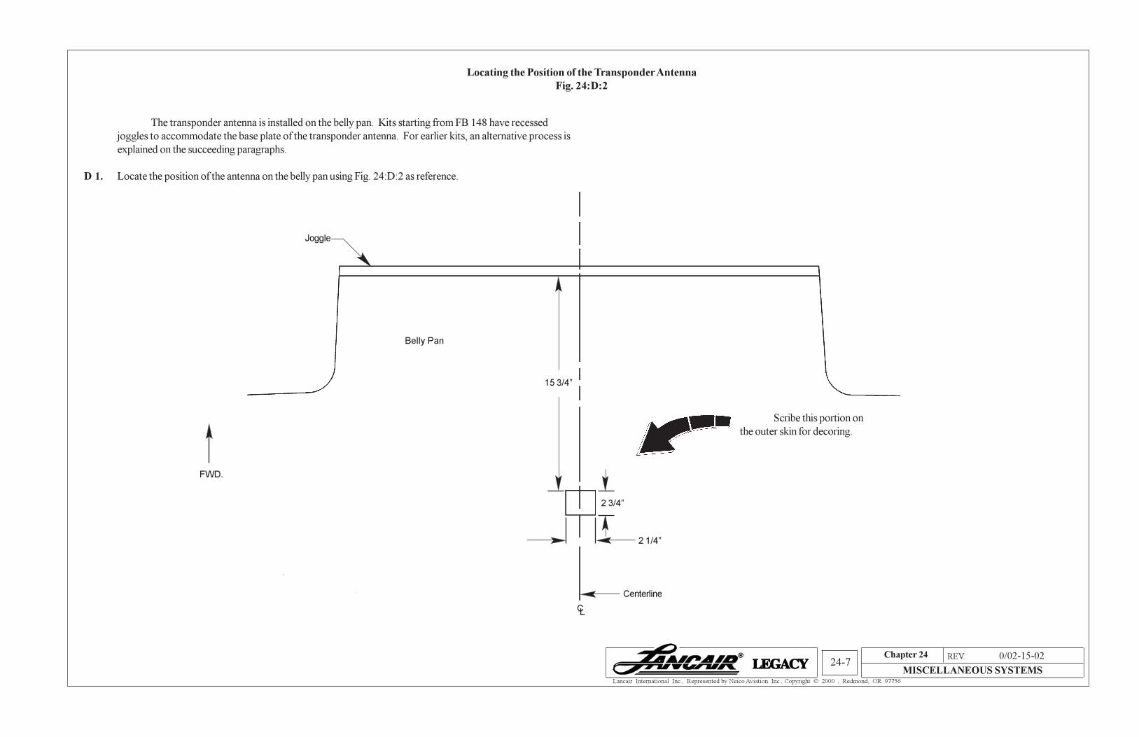
The transponder antenna is installed on the belly pan. Kits starting from FB 148 have recessed
joggles to accommodate the base plate of the transponder antenna. For earlier kits, an alternative process is
explained on the succeeding paragraphs.
D 1. Locate the position of the antenna on the belly pan using Fig. 24:D:2 as reference.
Locating the Position of the Transponder Antenna
Fig. 24:D:2
Joggle
Belly Pan
FWD.
Scribe this portion on
the outer skin for decoring.
CL
Centerline
2 1/4”
2 3/4”
15 3/4”
Chapter 24 REV. 0/02-15-02
MISCELLANEOUS SYSTEMS24-8
Lancair International Inc., Represented by Neico Aviation Inc., Copyright © 2000 , Redmond, OR 97756
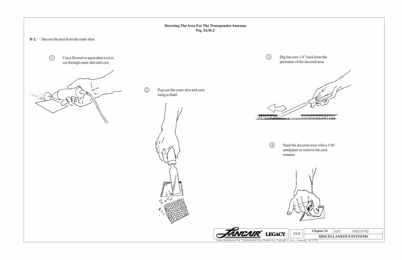
D 2. Decore the area from the outer skin.
Decoring The Area For The Transponder Antenna
Fig. 24:D:3
1 Use a Dremel or equivalent tool to
cut through outer skin and core.
2 Pop out the outer skin and core
using a chisel.
3 Dig the core 1/4” back from the
perimeter of the decored area.
4 Sand the decored area with a # 40
sandpaper to remove the core
remains.
Chapter 24 REV. 0/02-15-02
MISCELLANEOUS SYSTEMS24-9
Lancair International Inc., Represented by Neico Aviation Inc., Copyright © 2000 , Redmond, OR 97756
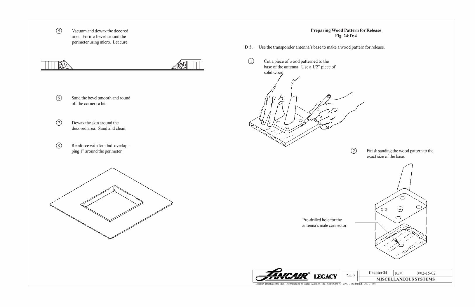
5 Vacuum and dewax the decored
area. Form a bevel around the
perimeter using micro. Let cure.
6 Sand the bevel smooth and round
off the corners a bit.
7 Dewax the skin around the
decored area. Sand and clean.
8 Reinforce with four bid overlap-
ping 1” around the perimeter.
D 3. Use the transponder antenna’s base to make a wood pattern for release.
Preparing Wood Pattern for Release
Fig. 24:D:4
1 Cut a piece of wood patterned to the
base of the antenna. Use a 1/2” piece of
solid wood.
Pre-drilled hole for the
antenna’s male connector.
2 Finish sanding the wood pattern to the
exact size of the base.
Chapter 24 REV. 0/02-15-02
MISCELLANEOUS SYSTEMS24-10
Lancair International Inc., Represented by Neico Aviation Inc., Copyright © 2000 , Redmond, OR 97756
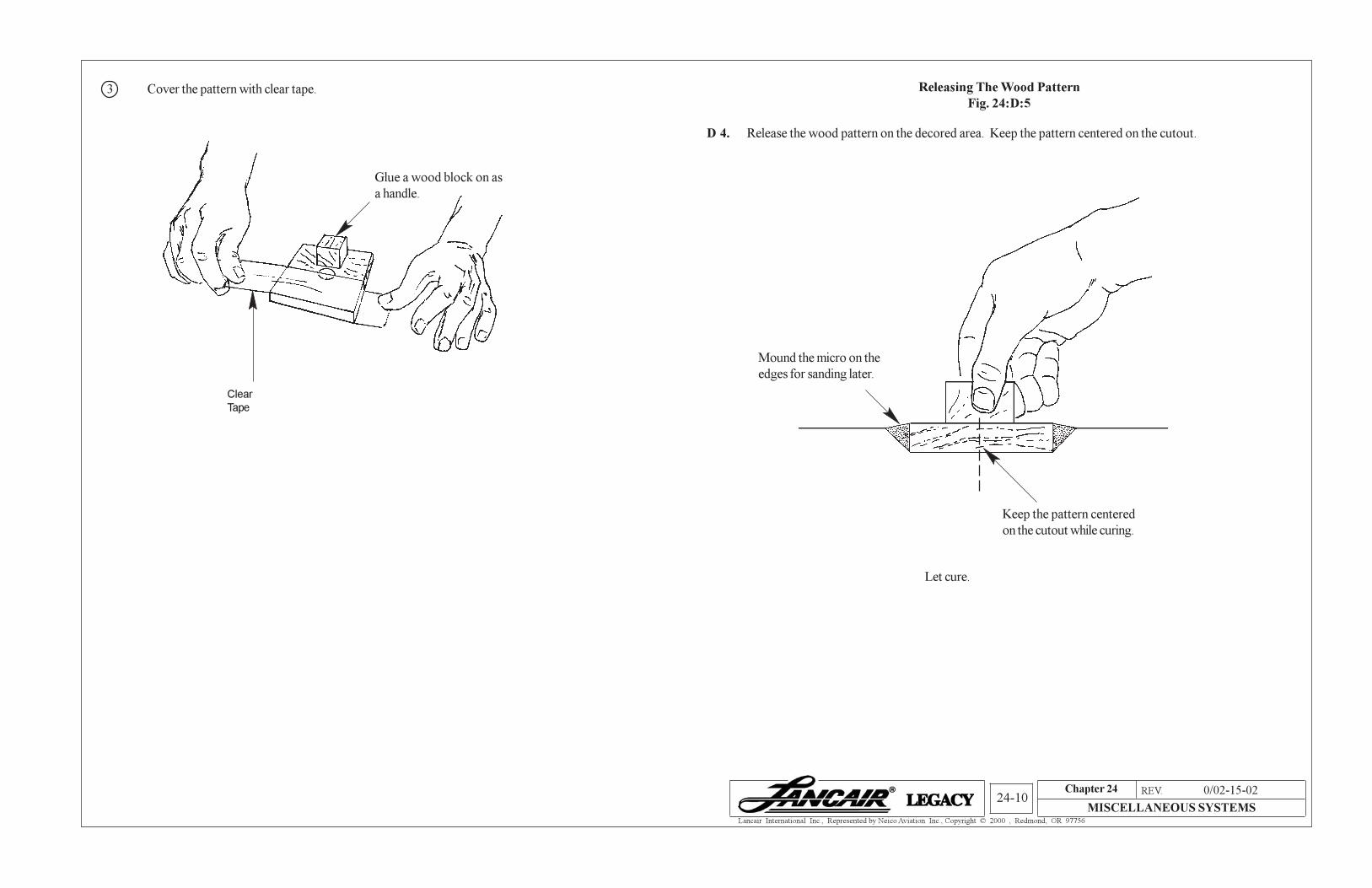
Clear
Tape
Glue a wood block on as
a handle.
3 Cover the pattern with clear tape.
D 4. Release the wood pattern on the decored area. Keep the pattern centered on the cutout.
Mound the micro on the
edges for sanding later.
Releasing The Wood Pattern
Fig. 24:D:5
Keep the pattern centered
on the cutout while curing.
Let cure.
Chapter 24 REV. 0/02-15-02
MISCELLANEOUS SYSTEMS24-11
Lancair International Inc., Represented by Neico Aviation Inc., Copyright © 2000 , Redmond, OR 97756
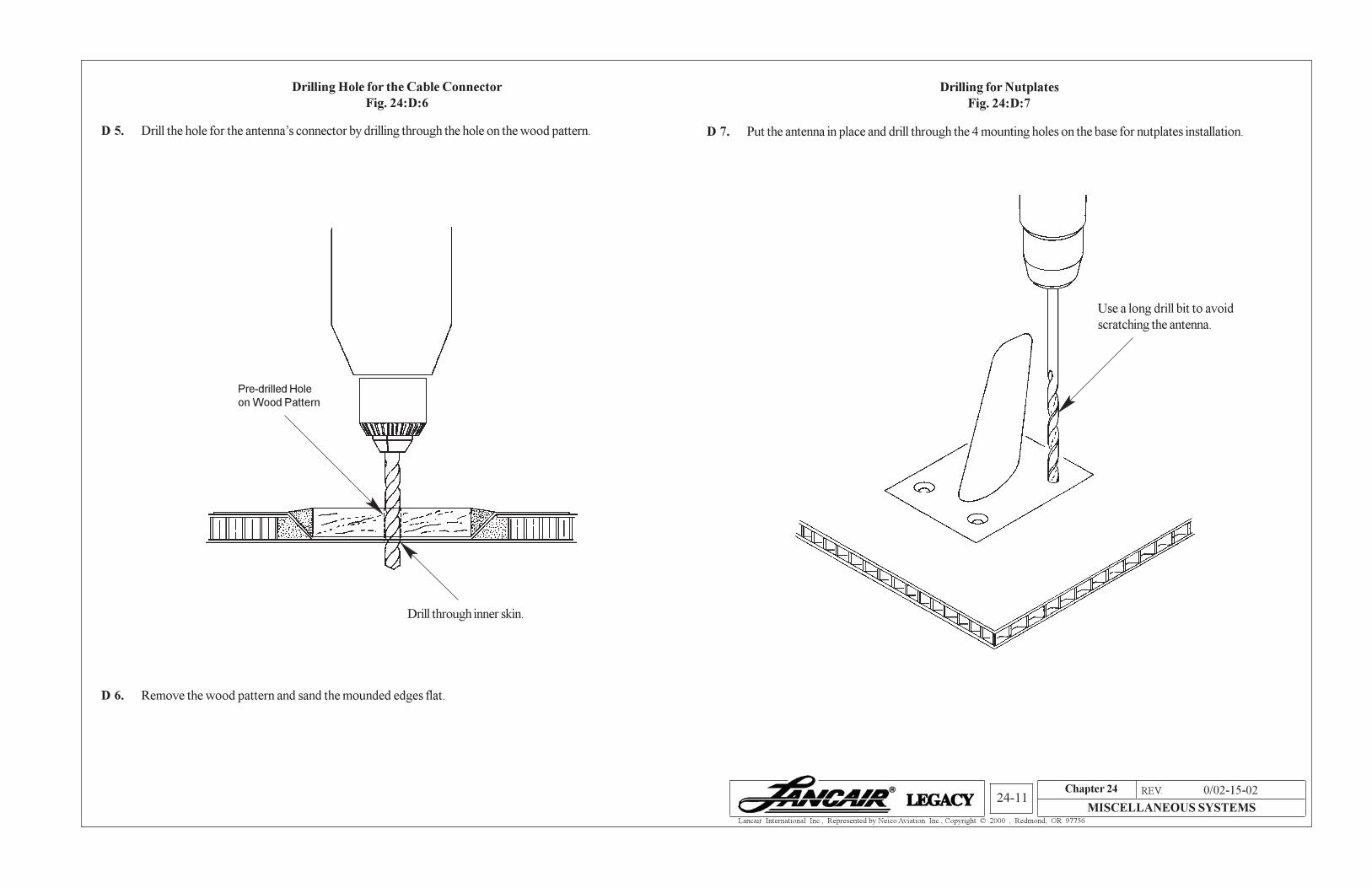
D 5. Drill the hole for the antenna’s connector by drilling through the hole on the wood pattern.
Drilling Hole for the Cable Connector
Fig. 24:D:6
Pre-drilled Hole
on Wood Pattern
Drill through inner skin.
D 6. Remove the wood pattern and sand the mounded edges flat.
D 7. Put the antenna in place and drill through the 4 mounting holes on the base for nutplates installation.
Drilling for Nutplates
Fig. 24:D:7
Use a long drill bit to avoid
scratching the antenna.
Chapter 24 REV. 0/02-15-02
MISCELLANEOUS SYSTEMS24-12
Lancair International Inc., Represented by Neico Aviation Inc., Copyright © 2000 , Redmond, OR 97756
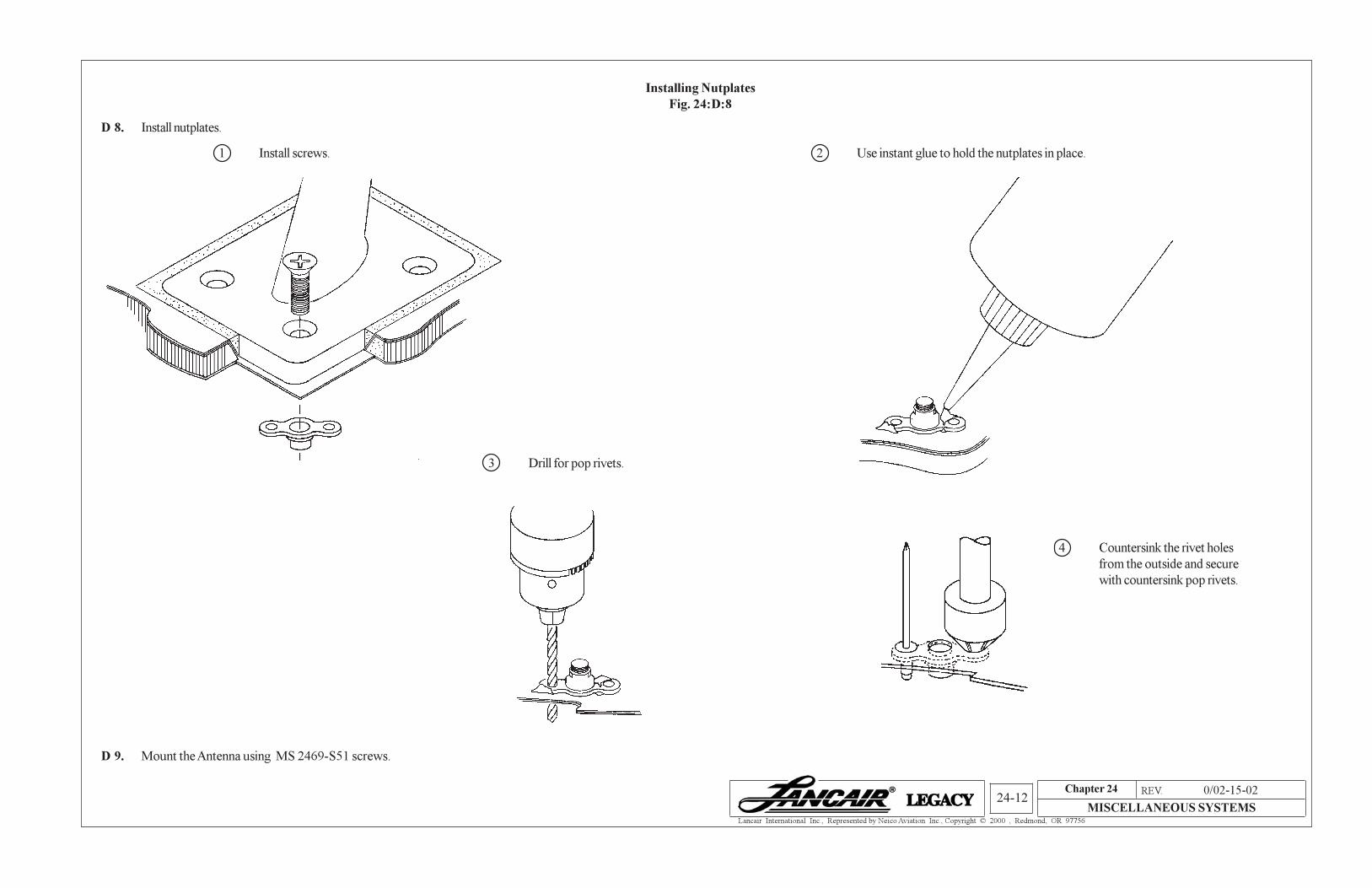
Installing Nutplates
Fig. 24:D:8
D 8. Install nutplates.
1 Install screws.
3 Drill for pop rivets.
4 Countersink the rivet holes
from the outside and secure
with countersink pop rivets.
2 Use instant glue to hold the nutplates in place.
D 9. Mount the Antenna using MS 2469-S51 screws.
Chapter 24 REV. 0/02-15-02
MISCELLANEOUS SYSTEMS24-13
Lancair International Inc., Represented by Neico Aviation Inc., Copyright © 2000 , Redmond, OR 97756
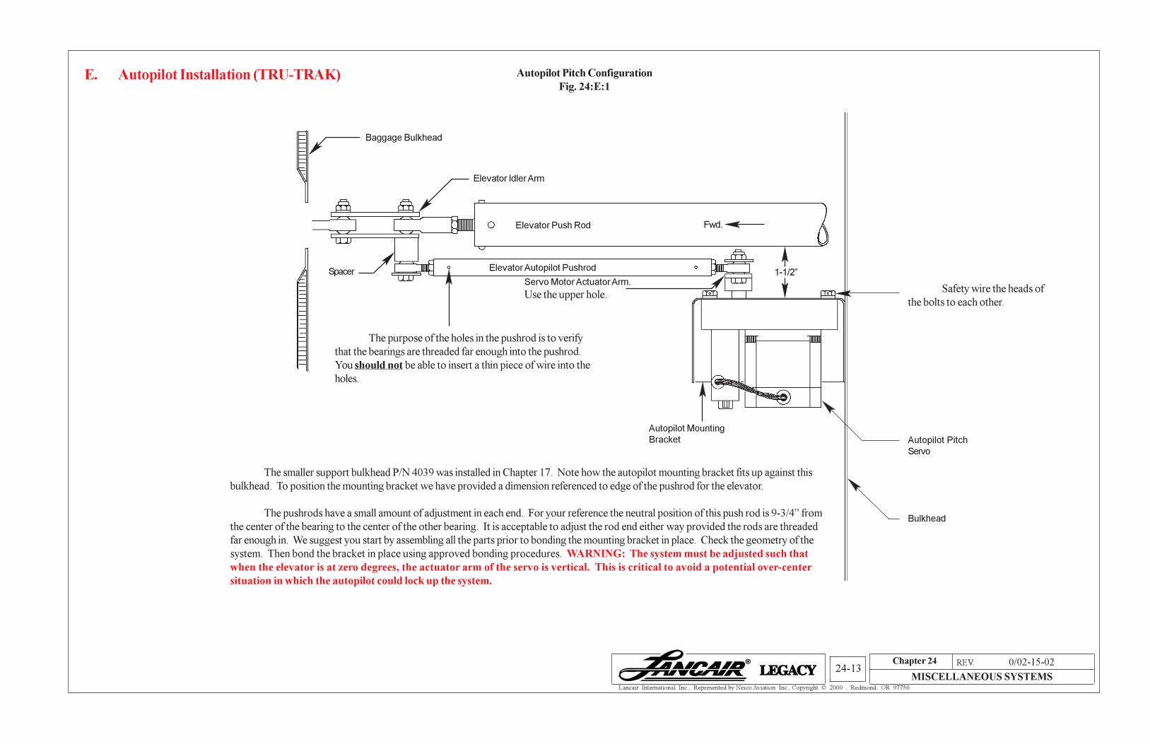
E. Autopilot Installation (TRU-TRAK) Autopilot Pitch Configuration
Fig. 24:E:1
Baggage Bulkhead
Elevator Idler Arm
Spacer
Elevator Push Rod
Elevator Autopilot Pushrod
Fwd.
Servo Motor Actuator Arm.
Use the upper hole.Safety wire the heads of
the bolts to each other.
Autopilot Mounting
Bracket Autopilot Pitch
Servo
Bulkhead
The purpose of the holes in the pushrod is to verify
that the bearings are threaded far enough into the pushrod.
You should not be able to insert a thin piece of wire into the
holes.
The smaller support bulkhead P/N 4039 was installed in Chapter 17. Note how the autopilot mounting bracket fits up against this
bulkhead. To position the mounting bracket we have provided a dimension referenced to edge of the pushrod for the elevator.
The pushrods have a small amount of adjustment in each end. For your reference the neutral position of this push rod is 9-3/4” from
the center of the bearing to the center of the other bearing. It is acceptable to adjust the rod end either way provided the rods are threaded
far enough in. We suggest you start by assembling all the parts prior to bonding the mounting bracket in place. Check the geometry of the
system. Then bond the bracket in place using approved bonding procedures. WARNING: The system must be adjusted such that
when the elevator is at zero degrees, the actuator arm of the servo is vertical. This is critical to avoid a potential over-center
situation in which the autopilot could lock up the system.
1-1/2”
Chapter 24 REV. 0/02-15-02
MISCELLANEOUS SYSTEMS24-14
Lancair International Inc., Represented by Neico Aviation Inc., Copyright © 2000 , Redmond, OR 97756
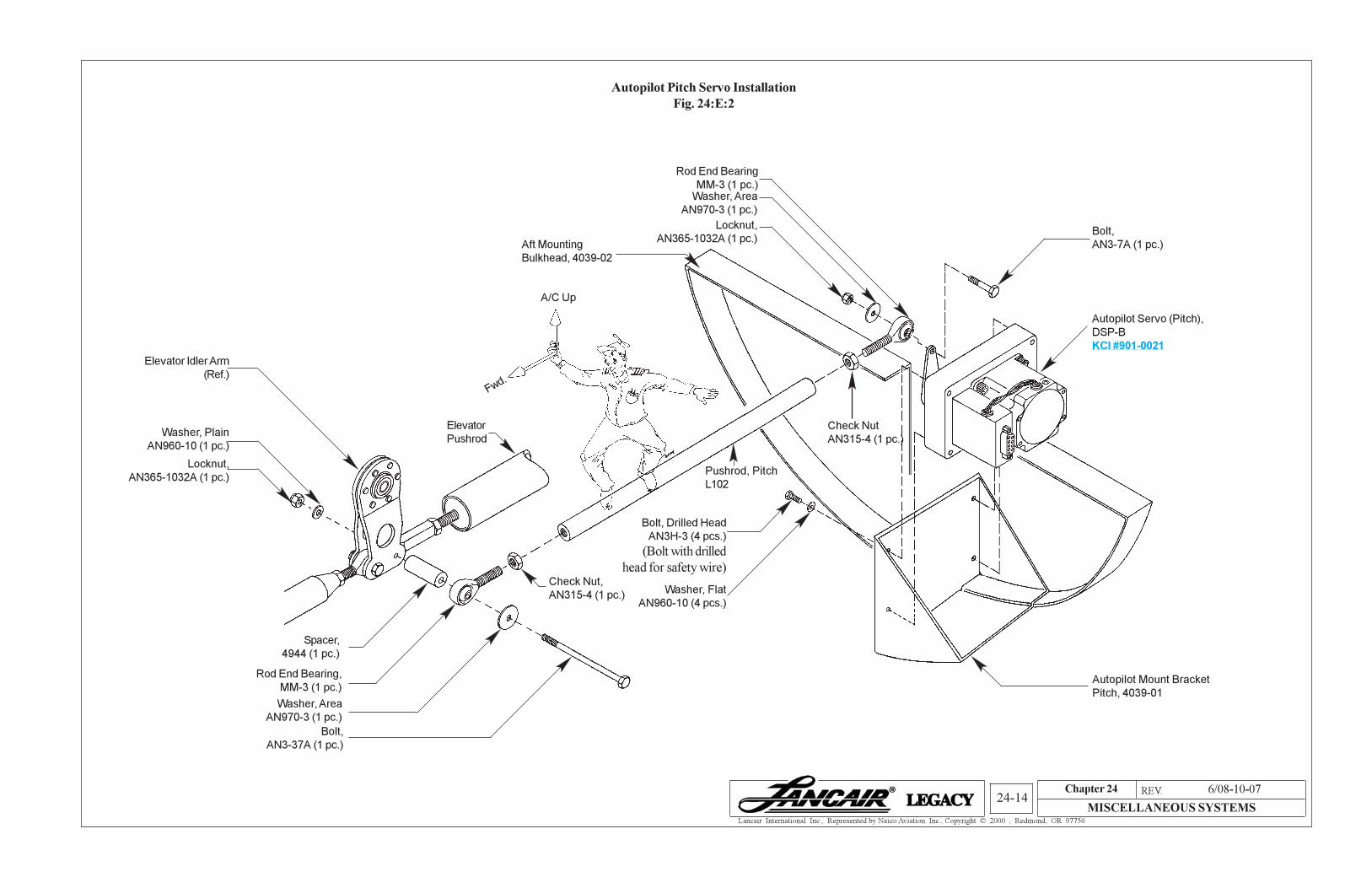
Autopilot Pitch Servo Installation
Fig. 24:E:2
Aft Mounting
Bulkhead, 4039-02
Locknut,
AN365-1032A (1 pc.)
Elevator Idler Arm
(Ref.)
Washer, Plain
AN960-10 (1 pc.)
Spacer,
4944 (1 pc.)
Rod End Bearing
MM-3 (1 pc.)
Washer, Area
AN970-3 (1 pc.)
Bolt,
AN3-37A (1 pc.)
Elevator
Pushrod
Check Nut
AN315-4 (1 pc.)
Bolt, Drilled Head
AN3H-3 (4 pcs.)
(Bolt with drilled
head for safety wire)
Autopilot Mount Bracket
Pitch, 4039-01
Washer, Flat
AN960-10 (4 pcs.)
Autopilot Servo (Pitch),
DSP-B
KCI #901-0021
Bolt,
AN3-7A (1 pc.)
Pushrod, Pitch
L102
Rod End Bearing,
MM-3 (1 pc.)
Washer, Area
AN970-3 (1 pc.)
Locknut,
AN365-1032A (1 pc.)
Check Nut,
AN315-4 (1 pc.)
A/C Up
Fwd.
6/08-10-07
Chapter 24 REV. 0/02-15-02
MISCELLANEOUS SYSTEMS24-15
Lancair International Inc., Represented by Neico Aviation Inc., Copyright © 2000 , Redmond, OR 97756
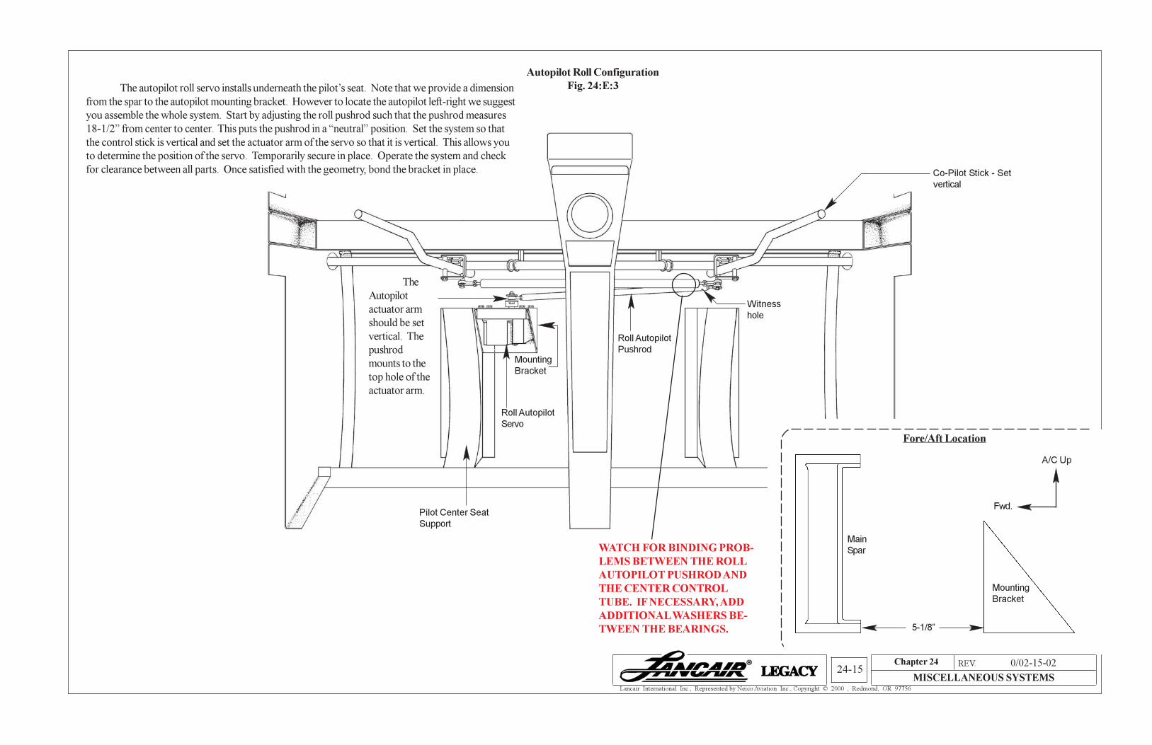
Mounting
Bracket
Autopilot Roll Configuration
Fig. 24:E:3The autopilot roll servo installs underneath the pilot’s seat. Note that we provide a dimension
from the spar to the autopilot mounting bracket. However to locate the autopilot left-right we suggest
you assemble the whole system. Start by adjusting the roll pushrod such that the pushrod measures
18-1/2” from center to center. This puts the pushrod in a “neutral” position. Set the system so that
the control stick is vertical and set the actuator arm of the servo so that it is vertical. This allows you
to determine the position of the servo. Temporarily secure in place. Operate the system and check
for clearance between all parts. Once satisfied with the geometry, bond the bracket in place.
The
Autopilot
actuator arm
should be set
vertical. The
pushrod
mounts to the
top hole of the
actuator arm.
Roll Autopilot
Servo
Pilot Center Seat
Support
Roll Autopilot
Pushrod
Witness
hole
WATCH FOR BINDING PROB-
LEMS BETWEEN THE ROLL
AUTOPILOT PUSHROD AND
THE CENTER CONTROL
TUBE. IF NECESSARY, ADD
ADDITIONAL WASHERS BE-
TWEEN THE BEARINGS.
Co-Pilot Stick - Set
vertical
Fore/Aft Location
Main
Spar
Mounting
Bracket
A/C Up
Fwd.
5-1/8”
Chapter 24 REV. 0/02-15-02
MISCELLANEOUS SYSTEMS24-16
Lancair International Inc., Represented by Neico Aviation Inc., Copyright © 2000 , Redmond, OR 97756
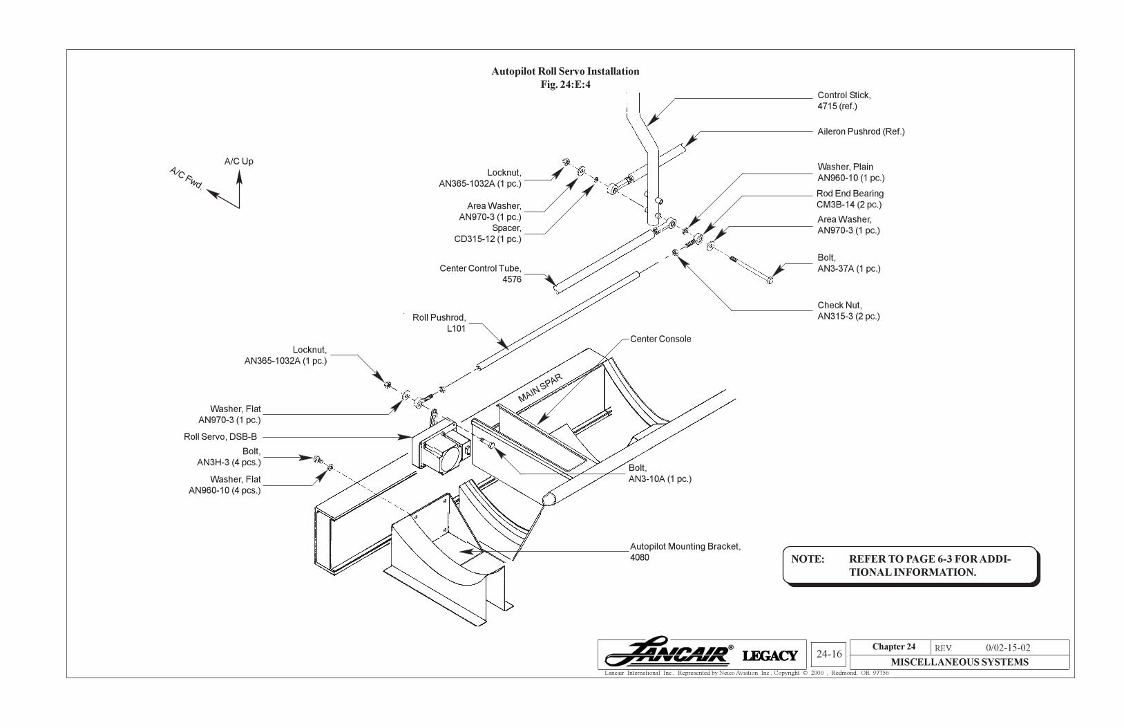
Autopilot Roll Servo Installation
Fig. 24:E:4
Locknut,
AN365-1032A (1 pc.)
Area Washer,
AN970-3 (1 pc.)
Spacer,
CD315-12 (1 pc.)
Center Control Tube,
4576
Control Stick,
4715 (ref.)
Aileron Pushrod (Ref.)
Washer, Plain
AN960-10 (1 pc.)
Check Nut,
AN315-3 (2 pc.)
Area Washer,
AN970-3 (1 pc.)
Roll Pushrod,
L101
Locknut,
AN365-1032A (1 pc.)
Washer, Flat
AN970-3 (1 pc.)
Bolt,
AN3-10A (1 pc.)
Roll Servo, DSB-B
Autopilot Mounting Bracket,
4080
Bolt,
AN3H-3 (4 pcs.)
Washer, Flat
AN960-10 (4 pcs.)
MAIN SPAR
NOTE: REFER TO PAGE 6-3 FOR ADDI-
TIONAL INFORMATION.
A/C Fwd.
A/C Up
Bolt,
AN3-37A (1 pc.)
Center Console
Rod End Bearing
CM3B-14 (2 pc.)