Embed Size (px)
Citation preview
Leica TM6100AUser Manual
Version 1.0English
2TM6100AIntroduction
IntroductionPurchase Congratulations on the purchase of a TM6100A instrument.
This manual contains important safety directions as well as instructions for setting up the product and operating it. Refer to "6 Safety Directions" for further informa-tion.Read carefully through the User Manual before you switch on the product.
Product identification
The type and the serial number of your product are indicated on the type plate.Enter the type and serial number in your manual and always refer to this information when you need to contact your agency or Leica Geosystems authorized service work-shop.
Type: _______________
Serial No.: _______________
Introduction TM6100A 3
Symbols The symbols used in this manual have the following meanings:Type Description
�Danger Indicates an imminently hazardous situation which, if not avoided, will result in death or serious injury.
�Warning Indicates a potentially hazardous situation or an unintended use which, if not avoided, could result in death or serious injury.
�Caution Indicates a potentially hazardous situation or an unintended use which, if not avoided, may result in minor or moderate injury and/or appreciable material, financial and environmental damage.
Important paragraphs which must be adhered to in practice as they enable the product to be used in a technically correct and efficient manner.
Trademarks • CompactFlash and CF are trademarks of SanDisk Corporation• Bluetooth is a registered trademark of Bluetooth SIG, IncAll other trademarks are the property of their respective owners.
Validity of this manual
Description
General This manual applies to all TM6100A instruments.
4TM6100AIntroduction
Available documentation
Name Description and Format
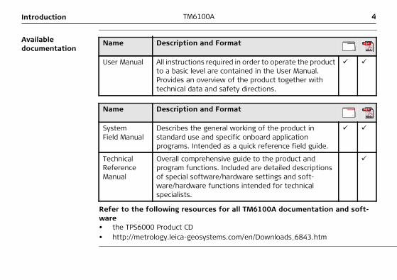
User Manual All instructions required in order to operate the product to a basic level are contained in the User Manual. Provides an overview of the product together with technical data and safety directions.
Name Description and Format
SystemField Manual
Describes the general working of the product in standard use and specific onboard application programs. Intended as a quick reference field guide.
Technical Reference Manual
Overall comprehensive guide to the product and program functions. Included are detailed descriptions of special software/hardware settings and soft-ware/hardware functions intended for technical specialists.
Refer to the following resources for all TM6100A documentation and soft-ware• the TPS6000 Product CD• http://metrology.leica-geosystems.com/en/Downloads_6843.htm
Table of Contents TM6100A 5
Table of ContentsIn this manual Chapter Page
1 Description of the System 8
1.1 System Components 81.2 System Concept 11
1.2.1 Software Concept 111.2.2 Data Storage and Data Conversion Concept 131.2.3 Power Concept 15
1.3 Container Contents 161.4 Instrument Components 17
2 User Interface 20
2.1 Keyboard 202.2 Hot Key Assignments 242.3 Screen 272.4 Operating Principles 292.5 Icons 35
3 Operation 37
3.1 Instrument Setup 373.2 Battery 40
3.2.1 Operating Principles 40
6TM6100ATable of Contents
3.2.2 Instrument Battery 413.3 Working with the CompactFlash Card 433.4 Accessing Survey Application Program 463.5 Built-in autocollimation device 493.6 Connection to Application Computer 513.7 Limitation of the horizontal and vertical movements 55
4 Check & Adjust 60
4.1 Overview 604.2 Preparation 634.3 Combined Adjustment (l, t, i and c) 654.4 Tilting Axis Adjustment (a) 694.5 Adjusting the Circular Level of the Instrument and Tribrach 744.6 Adjusting the Circular Level of the Prism Pole 764.7 Inspecting the Laser Plummet of the Instrument 774.8 Servicing the Tripod 794.9 Adjustment of the autocollimation reticule 80
5 Care and Transport 82
5.1 Transport 825.2 Storage 845.3 Cleaning and Drying 855.4 Maintenance 87
Table of Contents TM6100A 7
6 Safety Directions 88
6.1 General Introduction 886.2 Intended Use 896.3 Limits of Use 916.4 Responsibilities 926.5 Hazards of Use 936.6 Laser Classification 99
6.6.1 General 996.6.2 Laser Plummet 101
6.7 Electromagnetic Compatibility EMC 1046.8 FCC Statement, Applicable in U.S. 107
7 Technical Data 110
7.1 Angle Measurement 1107.2 Conformity to National Regulations 111
7.2.1 Communication side cover with Bluetooth 1117.3 General Technical Data of the Instrument 112
8 International Limited Warranty, Software License Agreement 119
1 - 8TM6100ADescription of the System
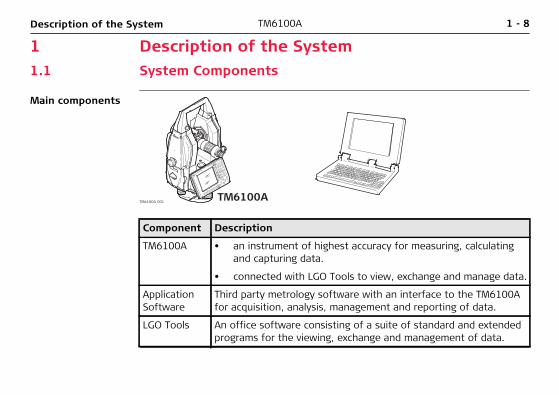
1 Description of the System1.1 System Components
Main components
TM6100A_001TM6100A
Component Description
TM6100A • an instrument of highest accuracy for measuring, calculating and capturing data.
• connected with LGO Tools to view, exchange and manage data.
Application Software
Third party metrology software with an interface to the TM6100A for acquisition, analysis, management and reporting of data.
LGO Tools An office software consisting of a suite of standard and extended programs for the viewing, exchange and management of data.
Description of the System TM6100A 1 - 9
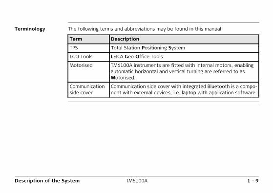
Terminology The following terms and abbreviations may be found in this manual:
Term Description
TPS Total Station Positioning System
LGO Tools LEICA Geo Office Tools
Motorised TM6100A instruments are fitted with internal motors, enabling automatic horizontal and vertical turning are referred to as Motorised.
Communication side cover
Communication side cover with integrated Bluetooth is a compo-nent with external devices, i.e. laptop with application software.
1 - 10TM6100ADescription of the System
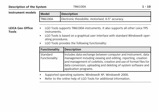
Instrument models Model Description
TM6100A Electronic theodolite, motorised, 0.5" accuracy.
LEICA Geo Office Tools
• LGO Tools supports TM6100A instruments. It also supports all other Leica TPS instruments.
• LGO Tools is based on a graphical user interface with standard Windows® oper-ating procedures.
• LGO Tools provides the following functionality:
Functionality Description
Standard Functionality
Includes data exchange between computer and instrument, data management including viewing and editing, reporting, creation and management of codelists, creation and use of format files for data conversion, uploading and deleting of system software and application programs.
• Supported operating systems: Windows® XP, Windows® 2000.• Refer to the online help of LGO Tools for additional information.
Description of the System TM6100A 1 - 11
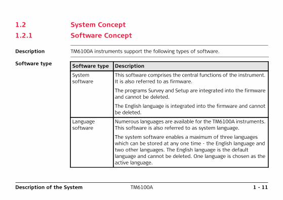
1.2 System Concept1.2.1 Software Concept
Description TM6100A instruments support the following types of software.
Software type Software type Description
System software
This software comprises the central functions of the instrument. It is also referred to as firmware.
The programs Survey and Setup are integrated into the firmware and cannot be deleted.
The English language is integrated into the firmware and cannot be deleted.
Language software
Numerous languages are available for the TM6100A instruments. This software is also referred to as system language.
The system software enables a maximum of three languages which can be stored at any one time - the English language and two other languages. The English language is the default language and cannot be deleted. One language is chosen as the active language.
1 - 12TM6100ADescription of the System
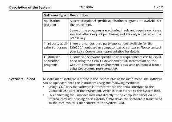
Software upload All instrument software is stored in the System RAM of the instrument. The software can be uploaded onto the instrument using the following methods:• Using LGO Tools the software is transferred via the serial interface to the
CompactFlash card in the instrument, which is then stored to the System RAM.• By connecting the CompactFlash card directly to the computer either via an
internal card slot housing or an external OMNI drive, the software is transferred to the card, which is then stored to the System RAM.
Application programs
A suite of optional specific application programs are available for the instrument.
Some of the programs are activated freely and require no license key and others require purchasing and are only activated with a license key.
Third party appli-cation programs
There are various third party applications available for the TM6100A, onboard or computer based software. Please contact your Leica Geosystems representative for details.
Customised application programs
Customised software specific to user requirements can be devel-oped using the GeoC++ development kit. Information on the GeoC++ development environment is available on request from a Leica Geosystems representative.
Software type Description
Description of the System TM6100A 1 - 13
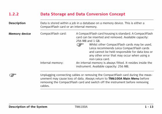
1.2.2 Data Storage and Data Conversion Concept
Description Data is stored within a job in a database on a memory device. This is either a CompactFlash card or an internal memory.
Memory device CompactFlash card: A CompactFlash card housing is standard. A CompactFlash card can be inserted and removed. Available capacity: 256 MB and 1 GB.
Whilst other CompactFlash cards may be used, Leica recommends Leica CompactFlash cards and cannot be held responsible for data loss or any other error that may occur when using a non-Leica card.
Internal memory: An internal memory is always fitted. It resides inside the instrument. Available capacity: 256 MB.
Unplugging connecting cables or removing the CompactFlash card during the meas-urement may cause loss of data. Always return to TM6100A Main Menu before removing the CompactFlash card and switch off the instrument before removing cables.
1 - 14TM6100ADescription of the System
Data conversion ExportData can be exported from a job in a wide range of ASCII formats. A standard set of Export Formats is delivered with the system. Customized export format can defined in Format Manager which is a PC tool in LEICA Geo Office Tools. Refer to the online help of LGO Tools for information on creating format files.Data can also be exported from a job in DXF or LandXML format.ImportData can be imported from ASCII, DXF, GSI8 or GSI16 format.
Transfer raw data to LGO Tools
Raw data can be transferred between the database on the CompactFlash card or the internal memory of the instrument and LGO Tools in two ways:• From the CompactFlash card or the internal memory directly via a serial interface
to a project in LGO Tools on a PC.• From the CompactFlash card using for example an OMNI drive as supplied by Leica
Geosystems to a project in LGO Tools on a PC.
CompactFlash cards can be used directly in an OMNI drive as supported by Leica Geosystems. Other PC card drives may require an adapter.
Description of the System TM6100A 1 - 15
1.2.3 Power Concept
General Use the Leica Geosystems batteries, chargers and accessories or accessories recom-mended by Leica Geosystems to ensure the correct functionality of the instrument.
Power options InstrumentPower for the instrument can be supplied either internally or externally. An external battery is connected to the instrument using a LEMO cable.Internal battery: One GEB241 battery fitted into the battery compartment.External battery: One GEB171 battery connected via cable
1 - 16TM6100ADescription of the System
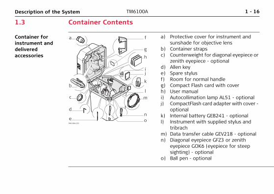
1.3 Container Contents
Container for instrument and delivered accessories
a
b
ij
lm
no
k
h
f
g
c
d
eTM6100A_039
a) Protective cover for instrument and sunshade for objective lens
b) Container strapsc) Counterweight for diagonal eyepiece or
zenith eyepiece - optionald) Allen keye) Spare stylusf) Room for normal handleg) Compact Flash card with coverh) User manuali) Autocollimation lamp AL51 - optionalj) CompactFlash card adapter with cover -
optionalk) Internal battery GEB241 - optionall) Instrument with supplied stylus and
tribrachm) Data transfer cable GEV218 - optionaln) Diagonal eyepiece GFZ3 or zenith
eyepiece GOK6 (eyepiece for steep sighting) - optional
o) Ball pen - optional
Description of the System TM6100A 1 - 17
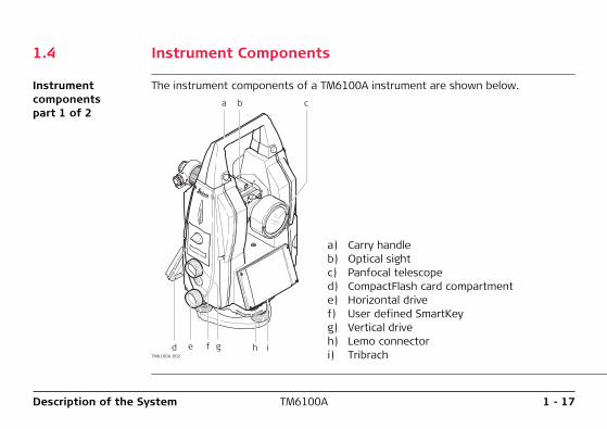
1.4 Instrument Components
Instrument components part 1 of 2
The instrument components of a TM6100A instrument are shown below.a b c
d f ge h iTM6100A_002
a) Carry handleb) Optical sightc) Panfocal telescoped) CompactFlash card compartmente) Horizontal drivef) User defined SmartKeyg) Vertical driveh) Lemo connectori) Tribrach
1 - 18TM6100ADescription of the System
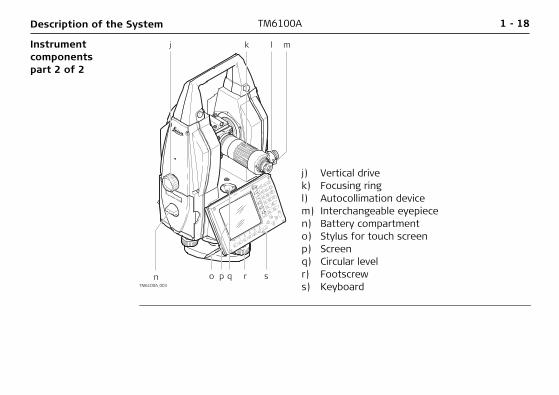
Instrument components part 2 of 2
j k l m
n q r spoTM6100A_003
j) Vertical drivek) Focusing ringl) Autocollimation devicem) Interchangeable eyepiecen) Battery compartmento) Stylus for touch screenp) Screenq) Circular levelr) Footscrews) Keyboard
Description of the System TM6100A 1 - 19
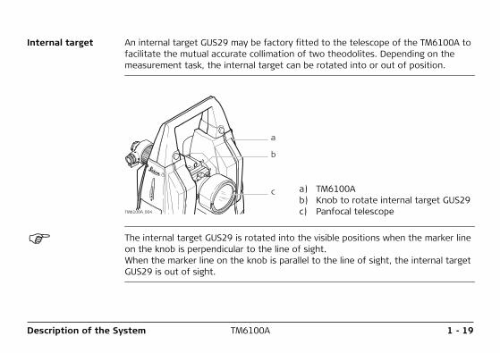
Internal target An internal target GUS29 may be factory fitted to the telescope of the TM6100A to facilitate the mutual accurate collimation of two theodolites. Depending on the measurement task, the internal target can be rotated into or out of position.
a
b
c
TM6100A_004
a) TM6100Ab) Knob to rotate internal target GUS29c) Panfocal telescope
The internal target GUS29 is rotated into the visible positions when the marker line on the knob is perpendicular to the line of sight. When the marker line on the knob is parallel to the line of sight, the internal target GUS29 is out of sight.
20TM6100AUser Interface
2 User Interface2.1 Keyboard
Keyboard a
b
c
d
e
fg
F2F1 F3 F4 F5 F6SHIFT
PgDn
PgUp
F7
F8 CE ESC
USER PROG
F9
F10
F11
F12 7 8 9
4 5 6
1 2 3
0 .
ABC DEF GHI
JKL MNO PQR
STU VWX YZ
/$% _@& *?!
ONOFF
TM6100A_005
User Interface TM6100A 21
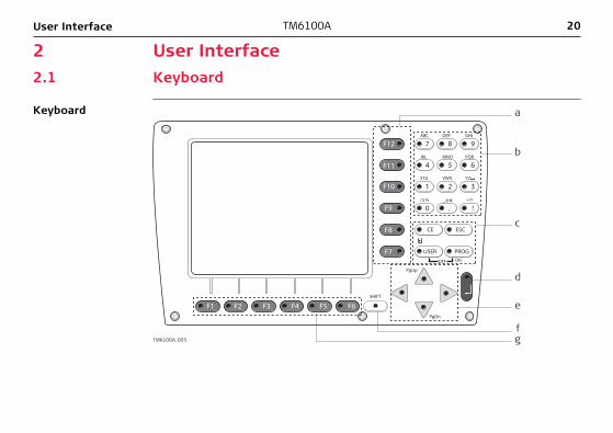
Keys H
a) Hot keys F7-F12 b) Alphanumeric keys c) CE, ESC, USER, PROG d) ENTER
e) Arrow keys f) SHIFT g) Function keys F1-F6
Key Description
Hot keys F7-F12 • Pre-defined keys to execute commands or access chosen screens.
• The hot key F13, the user defined SmartKey, is located between the horizontal and vertical drive on the right hand side cover.
Alphanumeric keys • To type letters and numbers.
CE • Clears all entry at the beginning of user input.• Clears the last character during user input.
ESC • Leaves the current menu or dialog without storing changes made.
USER • Calls the user defined menu.
PROG (ON) • If the instrument is off: to turn instrument on.• If the sensor is on: press at any time to select an applica-
tion program.
22TM6100AUser Interface
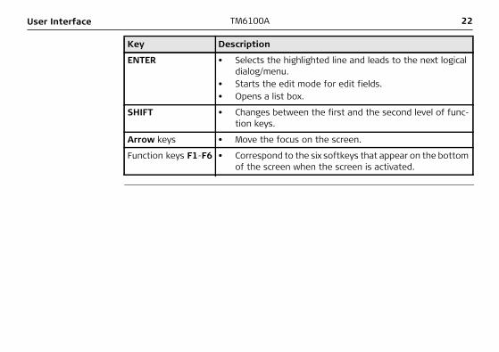
ENTER • Selects the highlighted line and leads to the next logical dialog/menu.
• Starts the edit mode for edit fields.• Opens a list box.
SHIFT • Changes between the first and the second level of func-tion keys.
Arrow keys • Move the focus on the screen.
Function keys F1-F6 • Correspond to the six softkeys that appear on the bottom of the screen when the screen is activated.
Key Description
User Interface TM6100A 23
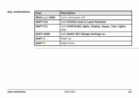
Key combinations Keys Description
PROG plus USER Turns instrument off.
SHIFT F12 Calls STATUS Level & Laser Plummet.
SHIFT F11 Calls CONFIGURE Lights, Display, Beeps, Text, Lights page.
SHIFT USER Calls QUICK SET Change Settings to:.
SHIFT Pages up.
SHIFT Pages down.
24TM6100AUser Interface
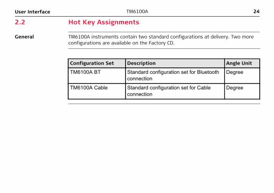
2.2 Hot Key Assignments
General TM6100A instruments contain two standard configurations at delivery. Two more configurations are available on the Factory CD.
Configuration Set Description Angle Unit
TM6100A BT Standard configuration set for Bluetooth connection
Degree
TM6100A Cable Standard configuration set for Cable connection
Degree
User Interface TM6100A 25
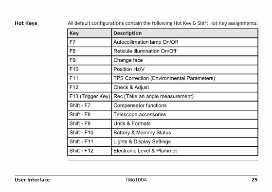
Hot Keys All default configurations contain the following Hot Key & Shift Hot Key assignments:
Key Description
F7 Autocollimation lamp On/Off
F8 Reticule illumination On/Off
F9 Change face
F10 Position Hz/V
F11 TPS Correction (Environmental Parameters)
F12 Check & Adjust
F13 (Trigger Key) Rec (Take an angle measurement)
Shift - F7 Compensator functions
Shift - F8 Telescope accessories
Shift - F9 Units & Formats
Shift - F10 Battery & Memory Status
Shift - F11 Lights & Display Settings
Shift - F12 Electronic Level & Plummet
26TM6100AUser Interface
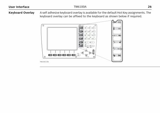
Keyboard Overlay A self adhesive keyboard overlay is available for the default Hot Key assignments. The keyboard overlay can be affixed to the keyboard as shown below if required.
F2F1 F3 F4 F5 F6SHIFT
PgDn
PgUp
F7
F8 CE ESC
USER PROG
F9
F10
F11
F12 7 8 9ABC DEF GHI
JKL MNO PQR
ONOFF
TM6100A_006
PgUp
CE ESC
USER PROG
7 8 9ABC DEF GHI
JKL MNO PQR
ONOFF
User Interface TM6100A 27
2.3 Screen
Screen
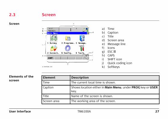
a) Timeb) Captionc) Titled) Screen areae) Message linef) Iconsg) ESC h) CAPSi) SHIFT iconj) Quick coding iconk) Softkeys
Elements of the screen
Element DescriptionTime The current local time is shown.Caption Shows location either in Main Menu, under PROG key or USER
key.Title Name of the screen is shown.Screen area The working area of the screen.
28TM6100AUser Interface
Message line Messages are shown for 10 s.Icons Shows current status information of the instrument. Refer to
"2.5 Icons". Can be used with touch screen.
ESC Can be used with touch screen. Same functionality as the fixed key ESC. The last operation will be undone.
CAPS The caps mode for upper case letters is active.The caps mode is activated and deactivated by pressing UPPER (F5) or LOWER (F5) in some screens.
SHIFT icon Shows the status of the SHIFT key; either first or second level of softkeys is selected. Can be used with touch screen and has the same functionality as the fixed key SHIFT.
Quick coding icon Shows the quick coding configuration. Can be used with touch screen to turn quick coding on and off.
Softkeys Commands can be executed using F1-F6 keys. The commands assigned to the softkeys are screen dependent. Can be used directly with touch screen.
Scroll bar Scrolls the screen area up and down.
Element Description
User Interface TM6100A 29
2.4 Operating Principles
Keyboard and touch screen
The user interface is operated either by the keyboard or by the touch screen with supplied stylus. The workflow is the same for keyboard and touch screen entry, the only difference lies in the way information is selected and entered.
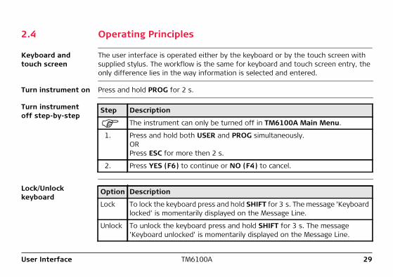
Turn instrument on Press and hold PROG for 2 s.
Turn instrument off step-by-step
Step Description
The instrument can only be turned off in TM6100A Main Menu.
1. Press and hold both USER and PROG simultaneously. OR Press ESC for more then 2 s.
2. Press YES (F6) to continue or NO (F4) to cancel.
Lock/Unlock keyboard
Option Description
Lock To lock the keyboard press and hold SHIFT for 3 s. The message ’Keyboard locked’ is momentarily displayed on the Message Line.
Unlock To unlock the keyboard press and hold SHIFT for 3 s. The message ’Keyboard unlocked’ is momentarily displayed on the Message Line.
30TM6100AUser Interface
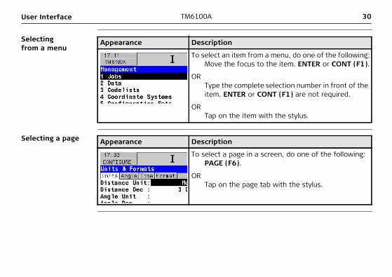
Selecting from a menu
Appearance Description
To select an item from a menu, do one of the following:Move the focus to the item. ENTER or CONT (F1).
ORType the complete selection number in front of the item. ENTER or CONT (F1) are not required.
ORTap on the item with the stylus.
Selecting a page Appearance Description
To select a page in a screen, do one of the following:PAGE (F6).
ORTap on the page tab with the stylus.
User Interface TM6100A 31
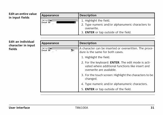
Edit an entire value in input fields
Appearance Description
1. Highlight the field.2. Type numeric and/or alphanumeric characters to
overwrite.3. ENTER or tap outside of the field.
Edit an individual character in input fields
Appearance Description
A character can be inserted or overwritten. The proce-dure is the same for both cases.
1. Highlight the field.
2. For the keyboard: ENTER. The edit mode is acti-vated where additional functions like insert and overwrite are available.
3. For the touch screen: Highlight the characters to be changed.
4. Type numeric and/or alphanumeric characters.
5. ENTER or tap outside of the field.
32TM6100AUser Interface
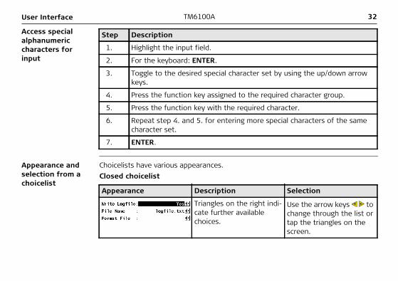
Access special alphanumeric characters for input
Step Description
1. Highlight the input field.
2. For the keyboard: ENTER.
3. Toggle to the desired special character set by using the up/down arrow keys.
4. Press the function key assigned to the required character group.
5. Press the function key with the required character.
6. Repeat step 4. and 5. for entering more special characters of the same character set.
7. ENTER.
Appearance and selection from a choicelist
Choicelists have various appearances.Closed choicelist
Appearance Description Selection
Triangles on the right indi-cate further available choices.
Use the arrow keys to change through the list or tap the triangles on the screen.
User Interface TM6100A 33
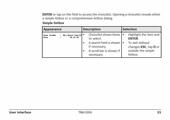
ENTER or tap on the field to access the choicelist. Opening a choicelist reveals either a simple listbox or a comprehensive listbox dialog.Simple listbox.
Appearance Description Selection
• Choicelist shows items to select.
• A search field is shown if necessary.
• A scroll bar is shown if necessary.
• Highlight the item and ENTER.
• To exit without changes ESC, tap or outside the simple listbox.
34TM6100AUser Interface
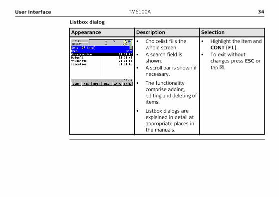
Listbox dialog.
Appearance Description Selection
• Choicelist fills the whole screen.
• A search field is shown.
• A scroll bar is shown if necessary.
• Highlight the item and CONT (F1).
• To exit without changes press ESC or tap .
• The functionality comprise adding, editing and deleting of items.
• Listbox dialogs are explained in detail at appropriate places in the manuals.
User Interface TM6100A 35
2.5 Icons
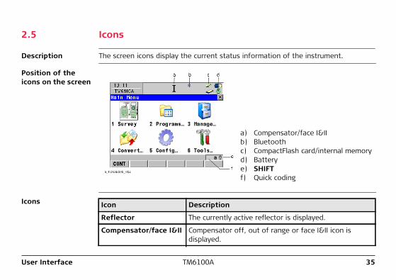
Description The screen icons display the current status information of the instrument.
Position of the icons on the screen
a) Compensator/face I&IIb) Bluetoothc) CompactFlash card/internal memoryd) Batterye) SHIFTf) Quick coding
Icons Icon Description
Reflector The currently active reflector is displayed.
Compensator/face I&II Compensator off, out of range or face I&II icon is displayed.
36TM6100AUser Interface
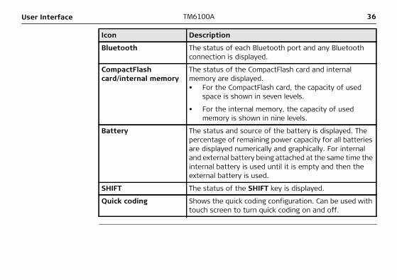
Bluetooth The status of each Bluetooth port and any Bluetooth connection is displayed.
CompactFlash card/internal memory
The status of the CompactFlash card and internal memory are displayed.• For the CompactFlash card, the capacity of used
space is shown in seven levels.
• For the internal memory, the capacity of used memory is shown in nine levels.
Battery The status and source of the battery is displayed. The percentage of remaining power capacity for all batteries are displayed numerically and graphically. For internal and external battery being attached at the same time the internal battery is used until it is empty and then the external battery is used.
SHIFT The status of the SHIFT key is displayed.
Quick coding Shows the quick coding configuration. Can be used with touch screen to turn quick coding on and off.
Icon Description
Operation TM6100A 37
3 Operation3.1 Instrument Setup
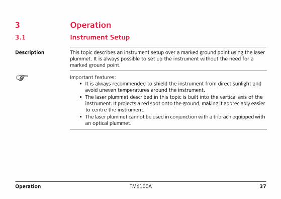
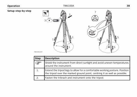
Description This topic describes an instrument setup over a marked ground point using the laser plummet. It is always possible to set up the instrument without the need for a marked ground point.
Important features:• It is always recommended to shield the instrument from direct sunlight and
avoid uneven temperatures around the instrument.• The laser plummet described in this topic is built into the vertical axis of the
instrument. It projects a red spot onto the ground, making it appreciably easier to centre the instrument.
• The laser plummet cannot be used in conjunction with a tribrach equipped with an optical plummet.
38TM6100AOperation
Setup step-by-step2
6
7
5 4
5
51
3
1
1
SHIFT
F12
TM6100A_007
Step Description
Shield the instrument from direct sunlight and avoid uneven temperatures around the instrument.
1. Extend the tripod legs to allow for a comfortable working posture. Position the tripod over the marked ground point, centring it as well as possible.
2. Fasten the tribrach and instrument onto the tripod.
Operation TM6100A 39
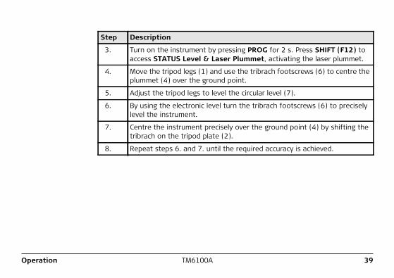
3. Turn on the instrument by pressing PROG for 2 s. Press SHIFT (F12) to access STATUS Level & Laser Plummet, activating the laser plummet.
4. Move the tripod legs (1) and use the tribrach footscrews (6) to centre the plummet (4) over the ground point.
5. Adjust the tripod legs to level the circular level (7).
6. By using the electronic level turn the tribrach footscrews (6) to precisely level the instrument.
7. Centre the instrument precisely over the ground point (4) by shifting the tribrach on the tripod plate (2).
8. Repeat steps 6. and 7. until the required accuracy is achieved.
Step Description
40TM6100AOperation
3.2 Battery3.2.1 Operating Principles
Primary use/charging• The battery must be charged prior to using it for the first time because it is deliv-
ered with an energy content as low as possible.• For new batteries or batteries that have been stored for a long time (> three
months), it is effectual to make only one charge/discharge cycle.• For Li-Ion batteries, a single discharging and charging cycle is sufficient. We
recommend carrying out the process when the battery capacity indicated on the charger or on a Leica Geosystems product deviates significantly form the actual battery capacity available.
• The permissible temperature range for charging is between 0°C to +40°C/+32°F to +104°F. For optimal charging we recommend charging the batteries at a low ambient temperature of +10°C to +20°C/+50°F to +68°F if possible.
• It is normal for the battery to become warm during charging. Using the chargers recommended by Leica Geosystems, it is not possible to charge the battery if the temperature is too high.
Operation/Discharging• The batteries can be operated from -20°C to +55°C/-4°F to +131°F.• Low operating temperatures reduce the capacity that can be drawn; very high
operating temperatures reduce the service life of the battery.
Operation TM6100A 41
3.2.2 Instrument Battery
Change battery step-by-step
2
6
1
7
35
4
TM6100A_008
Step Description
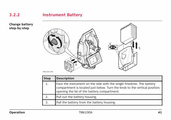
1. Face the instrument on the side with the single finedrive. The battery compartment is located just below. Turn the knob to the vertical position, opening the lid of the battery compartment.
2. Pull out the battery housing.
3. Pull the battery from the battery housing.
42TM6100AOperation
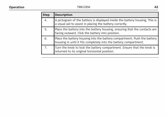
4. A pictogram of the battery is displayed inside the battery housing. This is a visual aid to assist in placing the battery correctly.
5. Place the battery into the battery housing, ensuring that the contacts are facing outward. Click the battery into position.
6. Place the battery housing into the battery compartment. Push the battery housing in until it fits completely into the battery compartment.
7. Turn the knob to lock the battery compartment. Ensure that the knob is returned to its original horizontal position.
Step Description
Operation TM6100A 43
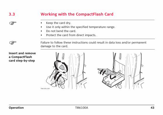
3.3 Working with the CompactFlash Card
• Keep the card dry.• Use it only within the specified temperature range.• Do not bend the card.• Protect the card from direct impacts.
Failure to follow these instructions could result in data loss and/or permanent damage to the card.
Insert and remove a CompactFlash card step-by-step
17
26 4
5 3
TM6100A_009
Step Description
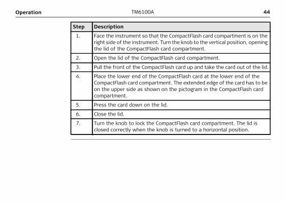
1. Face the instrument so that the CompactFlash card compartment is on the right side of the instrument. Turn the knob to the vertical position, opening the lid of the CompactFlash card compartment.
2. Open the lid of the CompactFlash card compartment.
3. Pull the front of the CompactFlash card up and take the card out of the lid.
4. Place the lower end of the CompactFlash card at the lower end of the CompactFlash card compartment. The extended edge of the card has to be on the upper side as shown on the pictogram in the CompactFlash card compartment.
5. Press the card down on the lid.
6. Close the lid.
7. Turn the knob to lock the CompactFlash card compartment. The lid is closed correctly when the knob is turned to a horizontal position.
44TM6100AOperation
Operation TM6100A 45
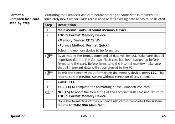
Format a CompactFlash card step-by-step
Formatting the CompactFlash card before starting to store data is required if a completely new CompactFlash card is used or if all existing data needs to be deleted.
Step Description1. Main Menu: Tools...\Format Memory Device.2. TOOLS Format Memory Device
<Memory Device: CF Card> <Format Method: Format Quick>Select the memory device to be formatted.By activating the format command all data will be lost. Make sure that all important data on the CompactFlash card has been backed up before formatting the card. Before formatting the internal memory make sure that all important data is first transferred to the PC.To exit the screen without formatting the memory device, press ESC. This returns to the previous screen without execution of any command.
3. CONT (F1).4. YES (F4) to complete the formatting of the CompactFlash card.
NO (F6) to abort the formatting of the CompactFlash card and return to TOOLS Format Memory Device.
5. Once the formatting of the CompactFlash card is completed the system returns to TM6100A Main Menu.
46TM6100AOperation
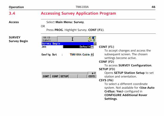
3.4 Accessing Survey Application Program
Access Select Main Menu: Survey.OR
Press PROG. Highlight Survey. CONT (F1).
SURVEY Survey Begin
CONT (F1) To accept changes and access the subsequent screen. The chosen settings become active.
CONF (F2) To access SURVEY Configuration.
SETUP (F3) Opens SETUP Station Setup to set station and orientation.
CSYS (F6) To select a different coordinate system. Not available for <Use Auto CrdSys: Yes> configured in CONFIGURE Additional Rover Settings.
Operation TM6100A 47
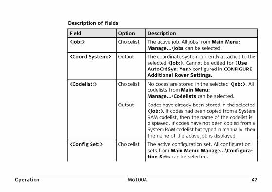
Description of fields
Field Option Description
<Job:> Choicelist The active job. All jobs from Main Menu: Manage...\Jobs can be selected.
<Coord System:> Output The coordinate system currently attached to the selected <Job:>. Cannot be edited for <Use AutoCrdSys: Yes> configured in CONFIGURE Additional Rover Settings.
<Codelist:> Choicelist No codes are stored in the selected <Job:>. All codelists from Main Menu: Manage...\Codelists can be selected.
Output Codes have already been stored in the selected <Job:>. If codes had been copied from a System RAM codelist, then the name of the codelist is displayed. If codes have not been copied from a System RAM codelist but typed in manually, then the name of the active job is displayed.
<Config Set:> Choicelist The active configuration set. All configuration sets from Main Menu: Manage...\Configura-tion Sets can be selected.
48TM6100AOperation
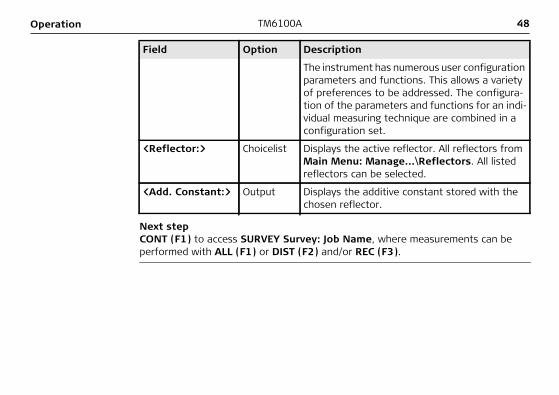
Next stepCONT (F1) to access SURVEY Survey: Job Name, where measurements can be performed with ALL (F1) or DIST (F2) and/or REC (F3).
The instrument has numerous user configuration parameters and functions. This allows a variety of preferences to be addressed. The configura-tion of the parameters and functions for an indi-vidual measuring technique are combined in a configuration set.
<Reflector:> Choicelist Displays the active reflector. All reflectors from Main Menu: Manage...\Reflectors. All listed reflectors can be selected.
<Add. Constant:> Output Displays the additive constant stored with the chosen reflector.
Field Option Description
Operation TM6100A 49
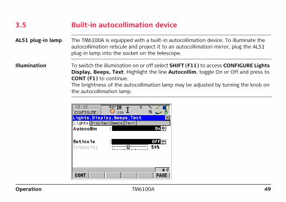
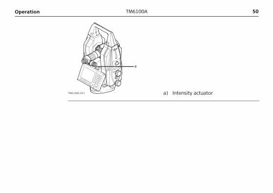
3.5 Built-in autocollimation device
AL51 plug-in lamp The TM6100A is equipped with a built-in autocollimation device. To illuminate the autocollimation reticule and project it to an autocollimation mirror, plug the AL51 plug-in lamp into the socket on the telescope.
Illumination To switch the illumination on or off select SHIFT (F11) to access CONFIGURE Lights Display, Beeps, Text. Highlight the line Autocollim, toggle On or Off and press to CONT (F1) to continue.The brightness of the autocollimation lamp may be adjusted by turning the knob on the autocollimation lamp.
TM6100A_041
a
a) Intensity actuator
50TM6100AOperation
Operation TM6100A 51
3.6 Connection to Application Computer
Connection types There are three basic connection types to connect a TM6100A to an application computer:• Cable connection via T-LINK• Cable connnection via USB Download Cable GEV218 or Y-Cable GEV220• Wireless Bluetooth connection
52TM6100AOperation
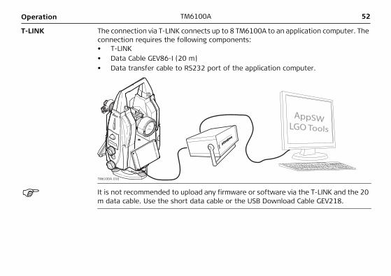
T-LINK The connection via T-LINK connects up to 8 TM6100A to an application computer. The connection requires the following components:• T-LINK• Data Cable GEV86-I (20 m)• Data transfer cable to RS232 port of the application computer.
TM6100A_010
It is not recommended to upload any firmware or software via the T-LINK and the 20 m data cable. Use the short data cable or the USB Download Cable GEV218.
Operation TM6100A 53
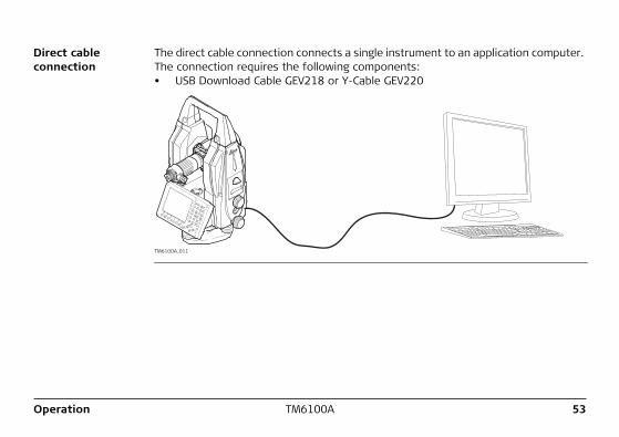
Direct cable connection
The direct cable connection connects a single instrument to an application computer. The connection requires the following components:• USB Download Cable GEV218 or Y-Cable GEV220
TM6100A_011
54TM6100AOperation
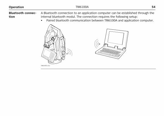
Bluetooth connec-tion
A Bluetooth connection to an application computer can be established through the internal bluetooth modul. The connection requires the following setup:• Paired bluetooth communication between TM6100A and application computer.
TM6100A_012
Operation TM6100A 55
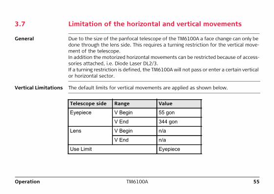
3.7 Limitation of the horizontal and vertical movements
General Due to the size of the panfocal telescope of the TM6100A a face change can only be done through the lens side. This requires a turning restriction for the vertical move-ment of the telescope.In addition the motorized horizontal movements can be restricted because of access-sories attached, i.e. Diode Laser DL2/3.If a turning restriction is defined, the TM6100A will not pass or enter a certain vertical or horizontal sector.
Vertical Limitations The default limits for vertical movements are applied as shown below.
Telescope side Range Value
Eyepiece V Begin 55 gon
V End 344 gon
Lens V Begin n/a
V End n/a
Use Limit Eyepiece
56TM6100AOperation
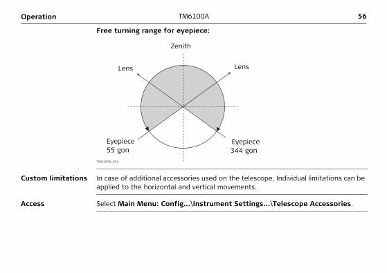
Free turning range for eyepiece:
TM6100A_042
LensLens
Zenith
Eyepiece55 gon
Eyepiece 344 gon
Custom limitations In case of additional accessories used on the telescope, Individual limitations can be applied to the horizontal and vertical movements.
Access Select Main Menu: Config...\Instrument Settings...\Telescope Accessories.
Operation TM6100A 57
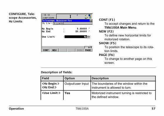
CONFIGURE, Tele-scope Accessories, Hz Limits CONT (F1)
To accept changes and return to the TM6100A Main Menu.
NEW (F2) To define new horizontal limits for motorized rotation.
SHOW (F5) To position the telescope to its rota-tion limits.
PAGE (F6) To change to another page on this screen.
Description of fields:
Field Option Description
<Hz Begin:> <Hz End:>
Output/user Input The boundaries of the window within the instrument is allowed to turn.
<Use Limit:> Yes Motorized instrument turning is restricted to the defined window.
58TM6100AOperation
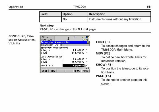
Next stepPAGE (F6) to change to the V Limit page.
CONFIGURE, Tele-scope Accessories, V Limits CONT (F1)
To accept changes and return to the TM6100A Main Menu.
NEW (F2) To define new horizontal limits for motorized rotation.
SHOW (F5) To position the telescope to its rota-tion limits.
PAGE (F6) To change to another page on this screen.
No Instruments turns without any limitation.
Field Option Description
Operation TM6100A 59
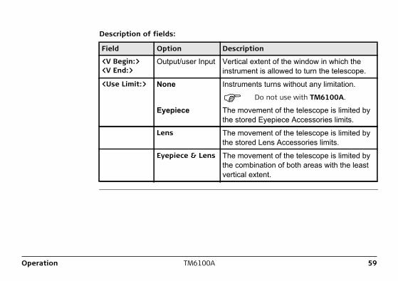
Description of fields:
Field Option Description
<V Begin:> <V End:>
Output/user Input Vertical extent of the window in which the instrument is allowed to turn the telescope.
<Use Limit:> None Instruments turns without any limitation.
Do not use with TM6100A.
Eyepiece The movement of the telescope is limited by the stored Eyepiece Accessories limits.
Lens The movement of the telescope is limited by the stored Lens Accessories limits.
Eyepiece & Lens The movement of the telescope is limited by the combination of both areas with the least vertical extent.
60TM6100ACheck & Adjust
4 Check & Adjust4.1 Overview
Description Leica instruments are manufactured, assembled and adjusted to the best possible quality. Quick temperature changes, shock or stress can cause deviations and decrease the instrument accuracy.It is therefore recommended to check and adjust the instrument from time to time. This can be done in the field by running through specific measurement procedures. The procedures are guided and have to be followed carefully and precisely as described in the following chapters. Some other instrument errors and mechanical parts can be adjusted mechanically.
Electronic adjustment
The following instrument errors can be checked and adjusted electronically: l, t Compensator longitudinal and transversal index errorsi Vertical index error, related to the standing axisc Hz collimation error, also called line of sight errora Tilting axis error
Every angle measured in the daily work is corrected automatically if the compensator and the Hz-corrections are activated in the instrument configuration. Select Main Menu: Config...\Instrument Settings...\Compensator to check the settings.
Check & Adjust TM6100A 61
View current adjustment errors
The currently used adjustment errors can be viewed under Main Menu: Tools.../Check & Adjust...\Current Values.
Mechanical adjustment
The following instrument parts can be adjusted mechanically:• Circular level on instrument and tribrach• Laser plummet• Optical plummet - option on tribrach• Allen screws on tripod
Precise measurements
To get precise measurements in the daily work, it is important:• To check and adjust the instrument from time to time.• To take high precision measurements during the check and adjust procedures.• To measure targets in two faces. Some of the instrument errors are eliminated
by averaging the angles from both faces.• Refer to "4.2 Preparation" to find more important points.
During the manufacturing process, the instrument errors are carefully determined and set to zero. As mentioned above, these errors can change and it is highly recom-mended to redetermine them in the following situations:• Before the first use• Before every high precision survey• After rough or long transportations• After long working periods
62TM6100ACheck & Adjust
• After long storage periods• If the temperature difference between current environment and the temperature
at the last calibration is more than 20°C
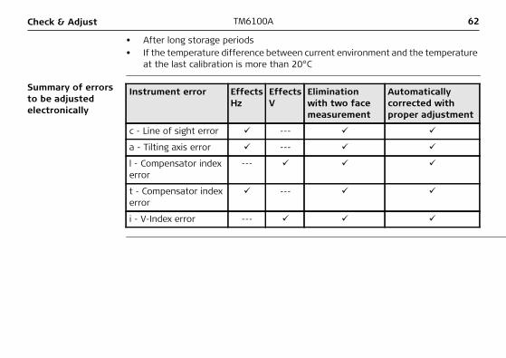
Summary of errors to be adjusted electronically
Instrument error Effects Hz
Effects V
Elimination with two face measurement
Automatically corrected with proper adjustment
c - Line of sight error ---
a - Tilting axis error ---
l - Compensator index error
---
t - Compensator index error
---
i - V-Index error ---

Check & Adjust TM6100A 63
4.2 Preparation
Before determining the instrument errors, the instrument has to be levelled-up using the electronic level. SHIFT F12 to access STATUS Level & Laser Plummet, Level page.The tribrach, the tripod and the underground should be very stable and secure from vibrations or other disturbances.
The instrument should be protected from direct sunlight in order to avoid thermal warming.It is also recommended to avoid strong heat shimmer and air turbulence. The best conditions are usually early in the morning or with overcast sky.
Before starting to work, the instrument has to become acclimatised to the ambient temperature. Approximately two minutes per °C of temperature difference from storage to working environment but at least 15 min should be taken into account.
Take the carry handle off the TM6100A when calibrating and measuring as the tele-scope may not turn to the second face with the carry handle mounted.Generally calibration and measurement set up should be carried out with the same instrument configuration.
64TM6100ACheck & Adjust
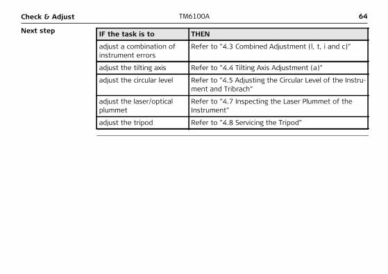
Next step IF the task is to THEN
adjust a combination of instrument errors
Refer to "4.3 Combined Adjustment (l, t, i and c)"
adjust the tilting axis Refer to "4.4 Tilting Axis Adjustment (a)"
adjust the circular level Refer to "4.5 Adjusting the Circular Level of the Instru-ment and Tribrach"
adjust the laser/optical plummet
Refer to "4.7 Inspecting the Laser Plummet of the Instrument"
adjust the tripod Refer to "4.8 Servicing the Tripod"
Check & Adjust TM6100A 65
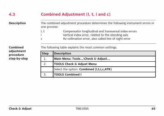
4.3 Combined Adjustment (l, t, i and c)
Description The combined adjustment procedure determines the following instrument errors in one process:l, t Compensator longitudinal and transversal index errorsi Vertical index error, related to the standing axisc Hz collimation error, also called line of sight error
Combined adjustment procedure step-by-step
The following table explains the most common settings.
Step Description
1. Main Menu: Tools...\Check & Adjust...
2. TOOLS Check & Adjust Menu
Select the option: Combined (l,t,i,c,ATR)
3. TOOLS Combined I
66TM6100ACheck & Adjust
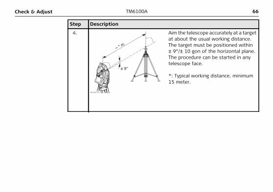
4.
± 9°
~ * m
TM6100A_013
Aim the telescope accurately at a target at about the usual working distance. The target must be positioned within ± 9°/± 10 gon of the horizontal plane. The procedure can be started in any telescope face.
*: Typical working distance, minimum 15 meter.
Step Description
Check & Adjust TM6100A 67
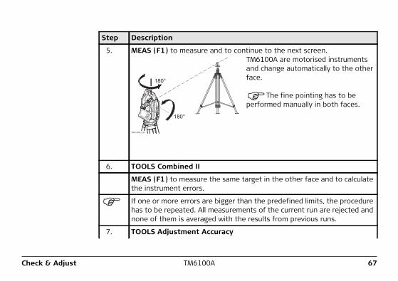
5. MEAS (F1) to measure and to continue to the next screen.
180°
180°
TM6100A_014
TM6100A are motorised instruments and change automatically to the other face.
The fine pointing has to be performed manually in both faces.
6. TOOLS Combined II
MEAS (F1) to measure the same target in the other face and to calculate the instrument errors.
If one or more errors are bigger than the predefined limits, the procedure has to be repeated. All measurements of the current run are rejected and none of them is averaged with the results from previous runs.
7. TOOLS Adjustment Accuracy
Step Description
68TM6100ACheck & Adjust
Next step IF the results are THEN
to be stored CONT (F1) overwrites the old adjustment errors with the new ones, if the Use status is set to Yes.
to be determined again
REDO (F2) rejects all new determined adjustment errors and repeats the whole procedure. Refer to step 3. of paragraph "Combined adjustment procedure step-by-step".
<No.of Meas:> Shows the number of runs executed. One run consists of a measurement in face I and face II.
<σ l Comp:> and similar lines show the standard deviations of the deter-mined adjustment errors. The standard deviations can be calculated from the second run onwards.
It is recommended to measure at least two runs.
8. MEAS (F5) if more runs have to be added. Continue with step 3.
OR
CONT (F1) to accept the measurements and to proceed to TOOLS Adjustment Results. No more runs can be added later.
Step Description
Check & Adjust TM6100A 69
4.4 Tilting Axis Adjustment (a)
Description This adjustment procedure determines the following instrument error:a Tilting axis error
Determination of tilting axis error step-by-step
The following table explains the most common settings.
Step Description
The Hz collimation error (c) has to be determined before starting this procedure.
1. Main Menu: Tools...\Check & Adjust...
2. TOOLS Check & Adjust Menu
Select the option: Tilting Axis (a)
70TM6100ACheck & Adjust
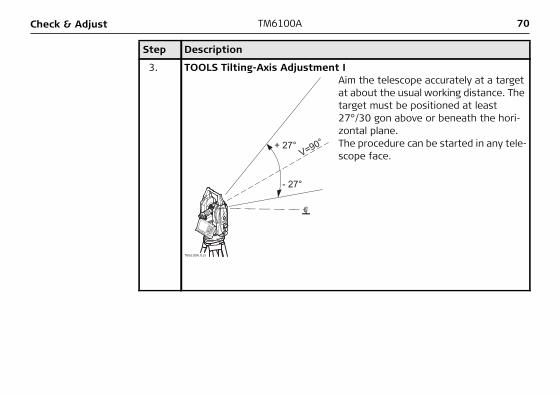
3. TOOLS Tilting-Axis Adjustment I
V=90°+ 27°
- 27°
TM6100A_015
Aim the telescope accurately at a target at about the usual working distance. The target must be positioned at least 27°/30 gon above or beneath the hori-zontal plane.The procedure can be started in any tele-scope face.
Step Description
Check & Adjust TM6100A 71
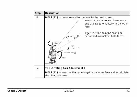
4. MEAS (F1) to measure and to continue to the next screen.
V=90°+ 27°
- 27°
180°
180°
TM6100A_040
TM6100A are motorised instruments and change automatically to the other face.
The fine pointing has to be performed manually in both faces.
5. TOOLS Tilting-Axis Adjustment II
MEAS (F1) to measure the same target in the other face and to calculate the tilting axis error.
Step Description
72TM6100ACheck & Adjust
If the error is bigger than the predefined limit, the procedure has to be repeated. The tilting axis measurements of the current run are then rejected and not averaged with the results from previous runs.
6. TOOLS T-Axis Adjustment Accuracy
<No.of Meas:> Shows the number of runs executed. One run consists of a measurement in face I and face II.
<σ a T-axis:> shows the standard deviation of the determined tilting axis error. The standard deviation can be calculated from the second run onwards.
It is recommended to measure at least two runs.
7. MEAS (F5) if more runs have to be added. Continue with step 3.
OR
CONT (F1) to accept the measurements and to proceed to TOOLS T-Axis Adjustment Result. No more runs can be added later.
Step Description
Check & Adjust TM6100A 73
Next step IF the results are THEN
to be stored CONT (F1) overwrites the old tilting axis error with the new one.
to be determined again
REDO (F2) rejects the new determined tilting axis error and repeats the whole procedure. Refer to step 3. of paragraph "Determination of tilting axis error step-by-step".
74TM6100ACheck & Adjust
4.5 Adjusting the Circular Level of the Instrument and Tribrach
Adjusting the circular level step-by-step
2
1
4
4
TM6100A 016
F12SHIFT
Step Description
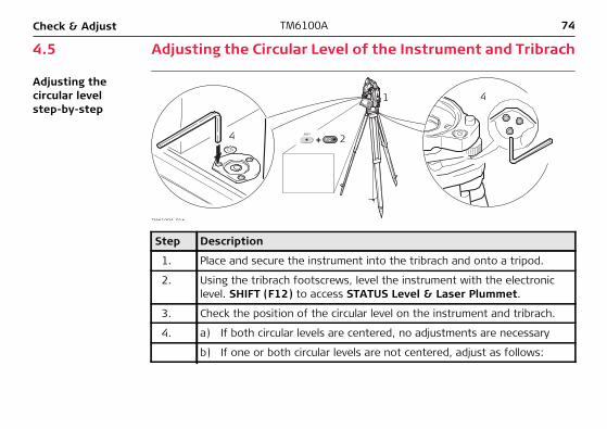
1. Place and secure the instrument into the tribrach and onto a tripod.
2. Using the tribrach footscrews, level the instrument with the electronic level. SHIFT (F12) to access STATUS Level & Laser Plummet.
3. Check the position of the circular level on the instrument and tribrach.
4. a) If both circular levels are centered, no adjustments are necessary
b) If one or both circular levels are not centered, adjust as follows:
Check & Adjust TM6100A 75
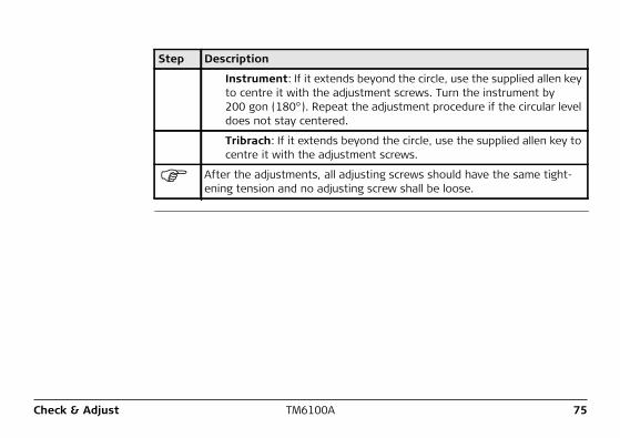
Instrument: If it extends beyond the circle, use the supplied allen key to centre it with the adjustment screws. Turn the instrument by 200 gon (180°). Repeat the adjustment procedure if the circular level does not stay centered.
Tribrach: If it extends beyond the circle, use the supplied allen key to centre it with the adjustment screws.
After the adjustments, all adjusting screws should have the same tight-ening tension and no adjusting screw shall be loose.
Step Description
76TM6100ACheck & Adjust
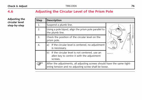
4.6 Adjusting the Circular Level of the Prism Pole
Adjusting the circular level step-by-step
Step Description
1. Suspend a plumb line.
1
2
4b
4a
TM6100A_017
2. Using a pole bipod, align the prism pole parallel to the plumb line.
3. Check the position of the circular level on the prism pole.
4. a) If the circular level is centered, no adjustment is necessary.
b) If the circular level is not centered, use an allen key to centre it with the adjustment screws.
After the adjustments, all adjusting screws should have the same tight-ening tension and no adjusting screw shall be loose.
Check & Adjust TM6100A 77
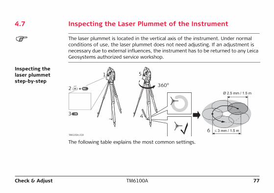
4.7 Inspecting the Laser Plummet of the Instrument
The laser plummet is located in the vertical axis of the instrument. Under normal conditions of use, the laser plummet does not need adjusting. If an adjustment is necessary due to external influences, the instrument has to be returned to any Leica Geosystems authorized service workshop.
Inspecting the laser plummet step-by-step
4
5
6
360°
≤ 3 mm / 1.5 m
Ø 2.5 mm / 1.5 m2
3
1
TM6100A_018
F12SHIFT
F6
The following table explains the most common settings.
Step Description
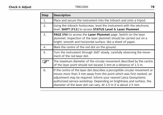
1. Place and secure the instrument into the tribrach and onto a tripod.
2. Using the tribrach footscrews, level the instrument with the electronic level. SHIFT (F12) to access STATUS Level & Laser Plummet.
3. PAGE (F6) to access the Laser Plummet page. Switch on the laser plummet. Inspection of the laser plummet should be carried out on a bright, smooth and horizontal surface, like a sheet of paper.
4. Mark the centre of the red dot on the ground.
5. Turn the instrument through 360° slowly, carefully observing the move-ment of the red laser dot.
The maximum diameter of the circular movement described by the centre of the laser point should not exceed 3 mm at a distance of 1.5 m.
6. If the centre of the laser dot describes a perceptible circular movement or moves more than 3 mm away from the point which was first marked, an adjustment may be required. Inform your nearest Leica Geosystems authorized service workshop. Depending on brightness and surface, the diameter of the laser dot can vary. At 1.5 m it is about 2.5 mm.
78TM6100ACheck & Adjust
Check & Adjust TM6100A 79
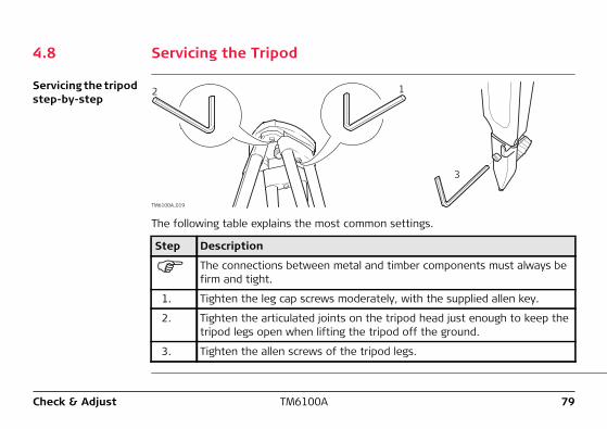
4.8 Servicing the Tripod
Servicing the tripod step-by-step
12
3
TM6100A_019
The following table explains the most common settings.
Step Description
The connections between metal and timber components must always be firm and tight.
1. Tighten the leg cap screws moderately, with the supplied allen key.
2. Tighten the articulated joints on the tripod head just enough to keep the tripod legs open when lifting the tripod off the ground.
3. Tighten the allen screws of the tripod legs.
80TM6100ACheck & Adjust
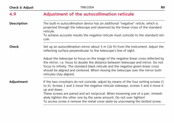
4.9 Adjustment of the autocollimation reticule
Description The built-in autocollimation device has an additional "negative" reticle, which is projected through the telescope and observed by the linear cross of the standard reticule.To achieve accurate results the negative reticule must coincide to the standard reti-cule.
Check Set up an autocollimation mirror about 5 m (16 ft) from the instrument. Adjust the reflecting surface perpendicular to the telescope’s line of sight.
Adjust the telescope to focus on the image of the negative linear cross reflected by the mirror, i.e. focus to double the distance between telescope and mirror. Do not focus to infinity. The standard black reticule and the negative green linear cross should be aligned and centered. When moving the telescope over the mirror both reticules stay aligned.
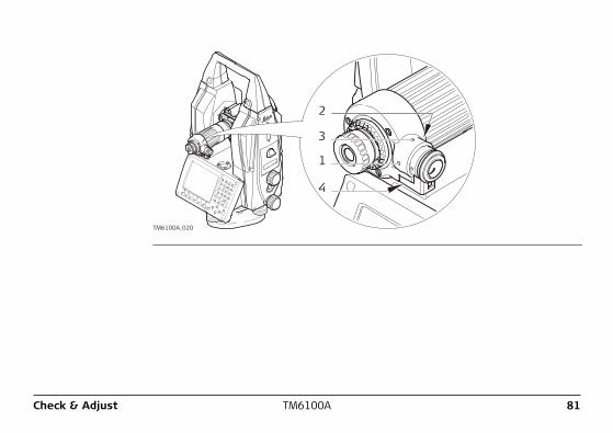
Adjustment If the two crosshairs do not coincide. adjust by means of the four setting screws (1 to 4). Screws 1 and 2 move the negative reticule sideways, screws 3 and 4 move it up and down. These screws are paired and act reciprocal. When loosening one of a pair, immedi-ately tighten the other one by the same amount. Do not over tighten!To access screw 4 remove the metal cover plate by unscrewing the slotted screw.
TM6100A_020
1
2
3
4
Check & Adjust TM6100A 81
82TM6100ACare and Transport
5 Care and Transport5.1 Transport
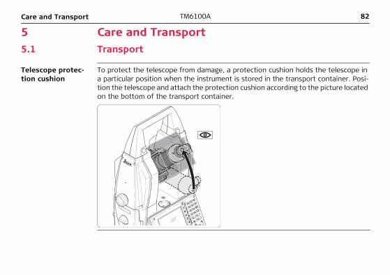
Telescope protec-tion cushion
To protect the telescope from damage, a protection cushion holds the telescope in a particular position when the instrument is stored in the transport container. Posi-tion the telescope and attach the protection cushion according to the picture located on the bottom of the transport container.
Care and Transport TM6100A 83
Transport in the field
When transporting the equipment in the field, always make sure that you• either carry the product in its original transport container,• or carry the tripod with its legs splayed across your shoulder, keeping the
attached product upright.
Transport in a road vehicle
Never carry the product loose in a road vehicle, as it can be affected by shock and vibration. Always carry the product in its transport container and secure it.
Shipping When transporting the product by rail, air or sea, always use the complete original Leica Geosystems packaging, transport container and cardboard box, or its equiva-lent, to protect against shock and vibration.
Shipping, transport of batteries
When transporting or shipping batteries, the person in charge of the product must ensure that the applicable national and international rules and regulations are observed. Before transportation or shipping, contact your local passenger or freight transport company.
Field adjustment After transport inspect the field adjustment parameters given in this user manual before using the product.
84TM6100ACare and Transport
5.2 Storage
Product Respect the temperature limits when storing the equipment, particularly in summer if the equipment is inside a vehicle. Refer to "7 Technical Data" for information about temperature limits.
Field adjustment After long periods of storage inspect the field adjustment parameters given in this user manual before using the product.
Li-Ion batteries • Refer to "7.3 General Technical Data of the Instrument" for information about storage temperature range.
• A storage temperature range of -20°C to +30°C/-4°F to +86°F in a dry environ-ment is recommended to minimize self-discharging of the battery.
• At the recommended storage temperature range, batteries containing a 10% to 50% charge can be stored for up to one year. After this storage period the batteries must be recharged.
• Remove batteries from the product and the charger before storing.• After storage recharge batteries before using.• Protect batteries from damp and wetness. Wet or damp batteries must be dried
before storing or use.
Care and Transport TM6100A 85
5.3 Cleaning and Drying
Product and accessories
• Blow dust off lenses and prisms.• Never touch the glass with your fingers.• Use only a clean, soft, lint-free cloth for cleaning. If necessary, moisten the cloth
with water or pure alcohol. Do not use other liquids; these may attack the polymer components.
Fogging of prisms Reflector prisms that are cooler than the ambient temperature tend to fog. It is not enough simply to wipe them. Keep them for some time inside your jacket or in the vehicle to allow them to adjust to the ambient temperature.
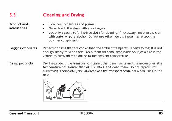
Damp products Dry the product, the transport container, the foam inserts and the accessories at a temperature not greater than 40°C / 104°F and clean them. Do not repack until everything is completely dry. Always close the transport container when using in the field.
86TM6100ACare and Transport
Cables and plugs Keep plugs clean and dry. Blow away any dirt lodged in the plugs of the connecting cables.
Care and Transport TM6100A 87
5.4 Maintenance
An inspection of the product must be done in a Leica Geosystems authorized service workshop. Leica Geosystems recommends an inspection of the product every 24 months.
As TM6100A instruments are equipped with a self-surveillance system designed for maximum motor performance and long maintenance cycles Leica Geosystems recom-mends inspection of the product whenever indicated in the message line of the user interface.
88TM6100ASafety Directions
6 Safety Directions6.1 General Introduction
Description The following directions should enable the person responsible for the product, and the person who actually uses the equipment, to anticipate and avoid operational hazards.
The person responsible for the product must ensure that all users understand these directions and adhere to them.
Safety Directions TM6100A 89
6.2 Intended Use
Permitted use • Measuring horizontal and vertical angles.• Recording measurements.• Visualizing the aiming direction and vertical axis.• Remote control of product.• Data communication with external appliances.• Transmission of measurement data to an external application PC.• Transmission of coordinates from an external application PC to the product for
inspection and build measurements.• Computing by means of software.
Adverse use • Use of the product without instruction.• Use outside of the intended limits.• Disabling safety systems.• Removal of hazard notices.• Opening the product using tools, for example screwdriver, unless this is specifi-
cally permitted for certain functions.• Modification or conversion of the product.• Use after misappropriation.• Use of products with obviously recognizable damages or defects.
90TM6100ASafety Directions
• Use with accessories from other manufacturers without the prior explicit approval of Leica Geosystems.
• Aiming directly into the sun.• Inadequate safeguards at the working site, for example when measuring on
roads.• Deliberate dazzling of third parties.• Controlling of machines, moving objects or similar monitoring application without
additional control- and safety installations.
�Warning Adverse use can lead to injury, malfunction and damage.It is the task of the person responsible for the equipment to inform the user about hazards and how to counteract them. The product is not to be operated until the user has been instructed on how to work with it.
Safety Directions TM6100A 91
6.3 Limits of Use
Environment Suitable for use in an atmosphere appropriate for permanent human habitation: not suitable for use in aggressive or explosive environments.
�Danger Local safety authorities and safety experts must be contacted before working in hazardous areas, or in close proximity to electrical installations or similar situations by the person in charge of the product.
92TM6100ASafety Directions
6.4 Responsibilities
Manufacturer of the product
Leica Geosystems AG, CH-9435 Heerbrugg, hereinafter referred to as Leica Geosys-tems, is responsible for supplying the product, including the user manual and original accessories, in a completely safe condition.
Manufacturers of non Leica Geosystems accessories
The manufacturers of non Leica Geosystems accessories for the product are respon-sible for developing, implementing and communicating safety concepts for their products, and are also responsible for the effectiveness of those safety concepts in combination with the Leica Geosystems product.
Person in charge of the product
The person in charge of the product has the following duties:• To understand the safety instructions on the product and the instructions in the
user manual.• To be familiar with local regulations relating to safety and accident prevention.• To inform Leica Geosystems immediately if the product and the application
becomes unsafe.• To ensure that the national laws, regulations and conditions for the operation of
radio transmitters are respected.
�Warning The person responsible for the product must ensure that it is used in accordance with the instructions. This person is also accountable for the training and the deployment of personnel who use the product and for the safety of the equipment in use.
Safety Directions TM6100A 93
6.5 Hazards of Use
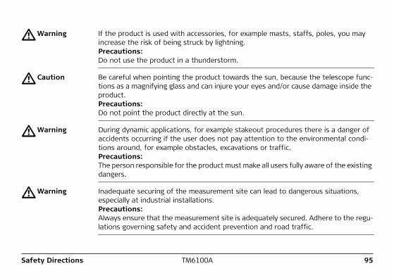
�Warning The absence of instruction, or the inadequate imparting of instruction, can lead to incorrect or adverse use, and can give rise to accidents with far-reaching human, material, financial and environmental consequences.Precautions:All users must follow the safety directions given by the manufacturer and the direc-tions of the person responsible for the product.
�Caution Watch out for erroneous measurement results if the product has been dropped or has been misused, modified, stored for long periods or transported.Precautions:Periodically carry out test measurements and perform the field adjustments indicated in the user manual, particularly after the product has been subjected to abnormal use and before and after important measurements.
�Caution Reflectors can cause personal injury and/or mechanical damage, when dropped.Precautions:Secure the reflector with a lanyard when moving the reflector.
94TM6100ASafety Directions
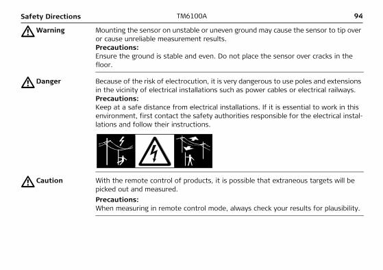
�Warning Mounting the sensor on unstable or uneven ground may cause the sensor to tip over or cause unreliable measurement results.Precautions:Ensure the ground is stable and even. Do not place the sensor over cracks in the floor.
�Danger Because of the risk of electrocution, it is very dangerous to use poles and extensions in the vicinity of electrical installations such as power cables or electrical railways.Precautions:Keep at a safe distance from electrical installations. If it is essential to work in this environment, first contact the safety authorities responsible for the electrical instal-lations and follow their instructions.
�Caution With the remote control of products, it is possible that extraneous targets will be picked out and measured.Precautions:When measuring in remote control mode, always check your results for plausibility.
Safety Directions TM6100A 95
�Warning If the product is used with accessories, for example masts, staffs, poles, you may increase the risk of being struck by lightning.Precautions:Do not use the product in a thunderstorm.
�Caution Be careful when pointing the product towards the sun, because the telescope func-tions as a magnifying glass and can injure your eyes and/or cause damage inside the product.Precautions:Do not point the product directly at the sun.
�Warning During dynamic applications, for example stakeout procedures there is a danger of accidents occurring if the user does not pay attention to the environmental condi-tions around, for example obstacles, excavations or traffic.Precautions:The person responsible for the product must make all users fully aware of the existing dangers.
�Warning Inadequate securing of the measurement site can lead to dangerous situations, especially at industrial installations.Precautions:Always ensure that the measurement site is adequately secured. Adhere to the regu-lations governing safety and accident prevention and road traffic.
96TM6100ASafety Directions
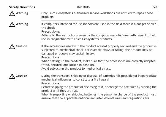
�Warning Only Leica Geosystems authorized service workshops are entitled to repair these products.
�Warning If computers intended for use indoors are used in the field there is a danger of elec-tric shock.Precautions:Adhere to the instructions given by the computer manufacturer with regard to field use in conjunction with Leica Geosystems products.
�Caution If the accessories used with the product are not properly secured and the product is subjected to mechanical shock, for example blows or falling, the product may be damaged or people may sustain injury.Precautions:When setting-up the product, make sure that the accessories are correctly adapted, fitted, secured, and locked in position.Avoid subjecting the product to mechanical stress.
�Caution During the transport, shipping or disposal of batteries it is possible for inappropriate mechanical influences to constitute a fire hazard.Precautions:Before shipping the product or disposing of it, discharge the batteries by running the product until they are flat.When transporting or shipping batteries, the person in charge of the product must ensure that the applicable national and international rules and regulations are
Safety Directions TM6100A 97
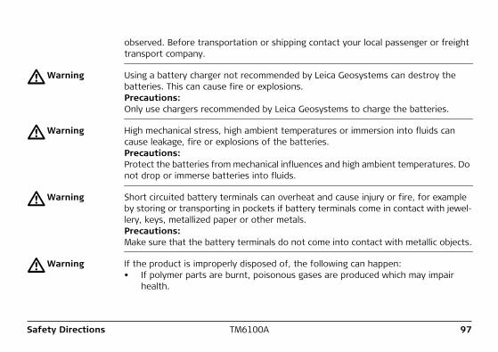
observed. Before transportation or shipping contact your local passenger or freight transport company.
�Warning Using a battery charger not recommended by Leica Geosystems can destroy the batteries. This can cause fire or explosions.Precautions:Only use chargers recommended by Leica Geosystems to charge the batteries.
�Warning High mechanical stress, high ambient temperatures or immersion into fluids can cause leakage, fire or explosions of the batteries.Precautions:Protect the batteries from mechanical influences and high ambient temperatures. Do not drop or immerse batteries into fluids.
�Warning Short circuited battery terminals can overheat and cause injury or fire, for example by storing or transporting in pockets if battery terminals come in contact with jewel-lery, keys, metallized paper or other metals.Precautions:Make sure that the battery terminals do not come into contact with metallic objects.
�Warning If the product is improperly disposed of, the following can happen:• If polymer parts are burnt, poisonous gases are produced which may impair
health.

98TM6100ASafety Directions
• If batteries are damaged or are heated strongly, they can explode and cause poisoning, burning, corrosion or environmental contamination.
• By disposing of the product irresponsibly you may enable unauthorized persons to use it in contravention of the regulations, exposing themselves and third parties to the risk of severe injury and rendering the environment liable to contamination.
• Improper disposal of silicone oil may cause environmental contamination.Precautions:
The product must not be disposed with household waste. Dispose of the product appropriately in accordance with the national regulations in force in your country. Always prevent access to the product by unauthorized personnel.
Product specific treatment and waste management information can be downloaded from the Leica Geosystems home page at http://www.leica-geosystems.com/treat-ment or received from your Leica Geosystems dealer.
Safety Directions TM6100A 99
6.6 Laser Classification6.6.1 General
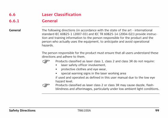
General The following directions (in accordance with the state of the art - international standard IEC 60825-1 (2007-03) and IEC TR 60825-14 (2004-02)) provide instruc-tion and training information to the person responsible for the product and the person who actually uses the equipment, to anticipate and avoid operational hazards.
The person responsible for the product must ensure that all users understand these directions and adhere to them.
Products classified as laser class 1, class 2 and class 3R do not require:• laser safety officer involvement,• protective clothes and eye wear,• special warning signs in the laser working areaif used and operated as defined in this user manual due to the low eye hazard level.Products classified as laser class 2 or class 3R may cause dazzle, flash-blindness and afterimages, particularly under low ambient light conditions.
100TM6100ASafety Directions
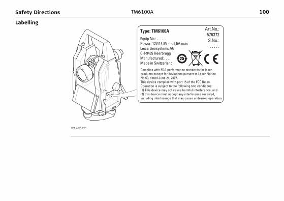
Labelling
TM6100A_024
Type: TM6100A
Equip.No.: . . . . . .Power: 12V/14,8V ---, 2,5A maxLeica Geosystems AGCH-9435 HeerbruggManufactured: . . . .Made in Switzerland
Complies with FDA performance standards for laser products except for deviations pursant to Laser Notice No.50, dated June 24, 2007.This device complies with part 15 of the FCC Rules. Operation is subject to the following two conditions:(1) This device may not cause harmful interference, and (2) this device must accept any interference received, including interference that may cause undesired operation.
Art.No.:576372S.No.:. . . . .
25
Safety Directions TM6100A 101
6.6.2 Laser Plummet
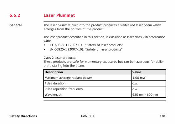
General The laser plummet built into the product produces a visible red laser beam which emerges from the bottom of the product.
The laser product described in this section, is classified as laser class 2 in accordance with:• IEC 60825-1 (2007-03): "Safety of laser products"• EN 60825-1 (2007-10): "Safety of laser products"
Class 2 laser products:These products are safe for momentary exposures but can be hazardous for delib-erate staring into the beam.
Description Value
Maximum average radiant power 1.00 mW
Pulse duration c.w.
Pulse repetition frequency c.w.
Wavelength 620 nm - 690 nm
102TM6100ASafety Directions
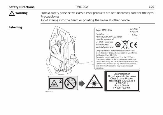
�Warning From a safety perspective class 2 laser products are not inherently safe for the eyes.Precautions:Avoid staring into the beam or pointing the beam at other people.
Labelling
TM6100A_022
Type: TM6100A
Equip.No.: . . . . . .Power: 12V/14,8V ---, 2,5A maxLeica Geosystems AGCH-9435 HeerbruggManufactured: . . . .Made in Switzerland
Complies with FDA performance standards for laser products except for deviations pursant to Laser Notice No.50, dated June 24, 2007.This device complies with part 15 of the FCC Rules. Operation is subject to the following two conditions:(1) This device may not cause harmful interference, and (2) this device must accept any interference received, including interference that may cause undesired operation.
Art.No.:576372
S.No.:. . . . .
25
Laser RadiationDo not stare into the beam
Class 2 Laser Productaccording to IEC 60825-1
( 2007-03 )Po ≤ 1.00 mW
l = 620 - 690 nm
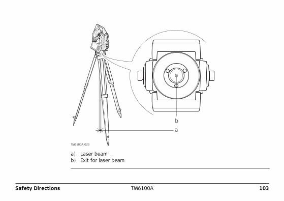
ba
TM6100A_023
a) Laser beamb) Exit for laser beam
Safety Directions TM6100A 103
104TM6100ASafety Directions
6.7 Electromagnetic Compatibility EMC
Description The term Electromagnetic Compatibility is taken to mean the capability of the product to function smoothly in an environment where electromagnetic radiation and elec-trostatic discharges are present, and without causing electromagnetic disturbances to other equipment.
�Warning Electromagnetic radiation can cause disturbances in other equipment.
Although the product meets the strict regulations and standards which are in force in this respect, Leica Geosystems cannot completely exclude the possibility that other equipment may be disturbed.
�Caution There is a risk that disturbances may be caused in other equipment if the product is used in conjunction with accessories from other manufacturers, for example field computers, personal computers, two-way radios, non-standard cables or external batteries.Precautions:Use only the equipment and accessories recommended by Leica Geosystems. When combined with the product, they meet the strict requirements stipulated by the guidelines and standards. When using computers and two-way radios, pay attention to the information about electromagnetic compatibility provided by the manufac-turer.
Safety Directions TM6100A 105
�Caution Disturbances caused by electromagnetic radiation can result in erroneous measure-ments.Although the product meets the strict regulations and standards which are in force in this respect, Leica Geosystems cannot completely exclude the possibility that the product may be disturbed by very intense electromagnetic radiation, for example, near radio transmitters, two-way radios or diesel generators.Precautions:Check the plausibility of results obtained under these conditions.
�Warning If the product is operated with connecting cables attached at only one of their two ends, for example external supply cables, interface cables, the permitted level of electromagnetic radiation may be exceeded and the correct functioning of other products may be impaired. Precautions:While the product is in use, connecting cables, for example product to external battery, product to computer, must be connected at both ends.
106TM6100ASafety Directions
Radios or digital cellular phones
Use of product with radio or digital cellular phone devices:
�Warning Electromagnetic radiation can cause disturbances in other equipment, in installa-tions, in medical devices, for example pacemakers or hearing aids and in aircraft. It can also affect humans and animals.Precautions:Although the product meets in combination with radio or digital cellular phone devices recommended by Leica Geosystems the strict regulations and standards which are in force in this respect, Leica Geosystems cannot completely exclude the possibility that other equipment may be disturbed or that humans or animals may be affected.• Do not operate the product with radio or digital cellular phone devices in the
vicinity of filling stations or chemical installations, or in other areas where an explosion hazard exists.
• Do not operate the product with radio or digital cellular phone devices near to medical equipment.
• Do not operate the product with radio or digital cellular phone devices in aircraft.• Do not operate the product with radio or digital cellular phone devices for long
periods immediately next to your body.
Safety Directions TM6100A 107
6.8 FCC Statement, Applicable in U.S.
Applicability The greyed paragraph below is only applicable for products of the TM6100A System without radio, digital cellular phone devices or Bluetooth.
�Warning This equipment has been tested and found to comply with the limits for a Class B digital device, pursuant to part 15 of the FCC rules.These limits are designed to provide reasonable protection against harmful interfer-ence in a residential installation.This equipment generates, uses and can radiate radio frequency energy and, if not installed and used in accordance with the instructions, may cause harmful interfer-ence to radio communications. However, there is no guarantee that interference will not occur in a particular installation.If this equipment does cause harmful interference to radio or television reception, which can be determined by turning the equipment off and on, the user is encour-aged to try to correct the interference by one or more of the following measures:• Reorient or relocate the receiving antenna.• Increase the separation between the equipment and the receiver.• Connect the equipment into an outlet on a circuit different from that to which
the receiver is connected.• Consult the dealer or an experienced radio/TV technician for help.
108TM6100ASafety Directions
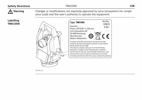
�Warning Changes or modifications not expressly approved by Leica Geosystems for compli-ance could void the user's authority to operate the equipment.
Labelling TM6100A
TM6100A_024
Type: TM6100A
Equip.No.: . . . . . .Power: 12V/14,8V ---, 2,5A maxLeica Geosystems AGCH-9435 HeerbruggManufactured: . . . .Made in Switzerland
Complies with FDA performance standards for laser products except for deviations pursant to Laser Notice No.50, dated June 24, 2007.This device complies with part 15 of the FCC Rules. Operation is subject to the following two conditions:(1) This device may not cause harmful interference, and (2) this device must accept any interference received, including interference that may cause undesired operation.
Art.No.:576372S.No.:. . . . .
25
Safety Directions TM6100A 109
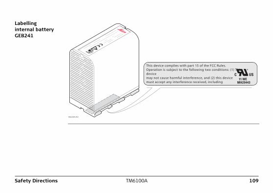
Labelling internal battery GEB241
TM6100A_043
.................................
.......................
......................
................................
..........................................
....
..........
.................................................................................
This device complies with part 15 of the FCC Rules. Operation is subject to the following two conditions: (1) This device may not cause harmful interference, and (2) this device must accept any interference received, including
110TM6100ATechnical Data
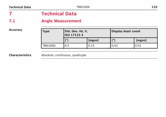
7 Technical Data7.1 Angle Measurement
Accuracy Type Std. Dev. Hz, V, ISO 17123-3
Display least count
["] [mgon] ["] [mgon]
TM6100A 0.5 0.15 0.01 0.01
Characteristics Absolute, continuous, quadruple

Technical Data TM6100A 111
7.2 Conformity to National Regulations7.2.1 Communication side cover with Bluetooth
Conformity to national regulations
• FCC Part 15 (applicable in US)• Hereby, Leica Geosystems AG, declares that the Communication side cover with
Bluetooth is in compliance with the essential requirements and other relevant provisions of Directive 1999/5/EC. The declaration of conformity may be consulted at http://www.leica-geosystems.com/ce.
Class 1 equipment according European Directive 1999/5/EC (R&TTE) can be placed on the market and be put into service without restric-tions in any EU Member state.
• The conformity for countries with other national regulations not covered by the FCC part 15 or European directive 1999/5/EC has to be approved prior to use and operation.
Frequency band 2402 - 2480 MHz
Output power Bluetooth: 5 mW
Antenna Type Internal Microstrip antennaGain 1.5 dBi
112TM6100ATechnical Data
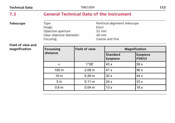
7.3 General Technical Data of the Instrument
Telescope Type Panfocal alignment telescopeImage ErectObjective aperture 52 mmClear objective diameter: 40 mmFocusing: Coarse and fine
Field of view and magnification Focussing
distanceField of view Magnification
Standard Eyepiece
Eyepiece FOK53
∞ 1°08’ 43 x 59 x
100 m 2.08 m 41 x 56 x
10 m 0.26 m 32 x 44 x
3 m 0.11 m 24 x 33 x
0.6 m 0.04 m 13 x 18 x
Technical Data TM6100A 113
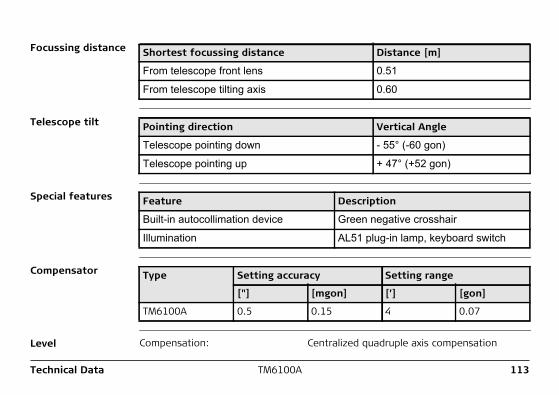
Focussing distance Shortest focussing distance Distance [m]
From telescope front lens 0.51
From telescope tilting axis 0.60
Telescope tilt Pointing direction Vertical Angle
Telescope pointing down - 55° (-60 gon)
Telescope pointing up + 47° (+52 gon)
Special features Feature Description
Built-in autocollimation device Green negative crosshair
Illumination AL51 plug-in lamp, keyboard switch
Compensator Type Setting accuracy Setting range
["] [mgon] [’] [gon]
TM6100A 0.5 0.15 4 0.07
Level Compensation: Centralized quadruple axis compensation
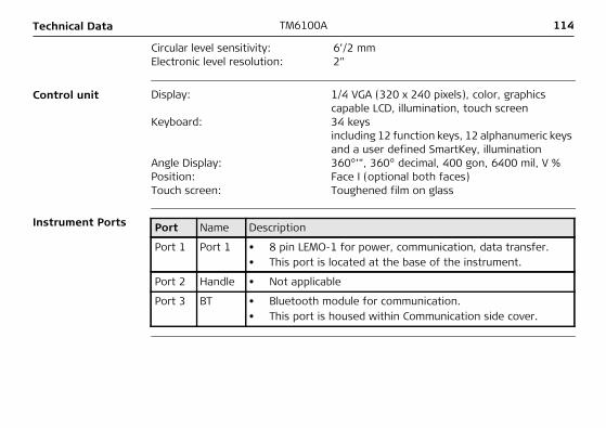
114TM6100ATechnical Data
Control unit Display: 1/4 VGA (320 x 240 pixels), color, graphics capable LCD, illumination, touch screen
Keyboard: 34 keysincluding 12 function keys, 12 alphanumeric keys and a user defined SmartKey, illumination
Angle Display: 360°’", 360° decimal, 400 gon, 6400 mil, V %Position: Face I (optional both faces)Touch screen: Toughened film on glass
Instrument Ports Port Name Description
Port 1 Port 1 • 8 pin LEMO-1 for power, communication, data transfer.• This port is located at the base of the instrument.
Port 2 Handle • Not applicable
Port 3 BT • Bluetooth module for communication.• This port is housed within Communication side cover.
Circular level sensitivity: 6’/2 mmElectronic level resolution: 2"
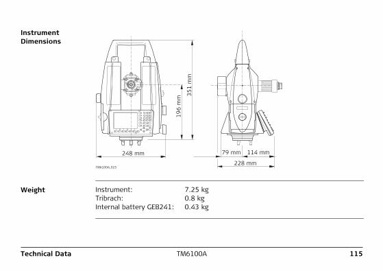
Technical Data TM6100A 115
Instrument Dimensions
196 m
m
351 m
m
248 mm 114 mm
228 mm
79 mm
TM6100A_025
Weight Instrument: 7.25 kgTribrach: 0.8 kgInternal battery GEB241: 0.43 kg
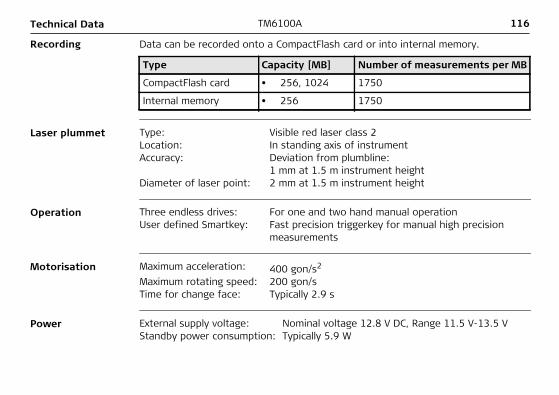
116TM6100ATechnical Data
Recording Data can be recorded onto a CompactFlash card or into internal memory.
Type Capacity [MB] Number of measurements per MB
CompactFlash card • 256, 1024 1750
Internal memory • 256 1750
Laser plummet Type: Visible red laser class 2Location: In standing axis of instrumentAccuracy: Deviation from plumbline:
1 mm at 1.5 m instrument heightDiameter of laser point: 2 mm at 1.5 m instrument height
Operation Three endless drives: For one and two hand manual operationUser defined Smartkey: Fast precision triggerkey for manual high precision
measurements
Motorisation Maximum acceleration: 400 gon/s2
Maximum rotating speed: 200 gon/sTime for change face: Typically 2.9 s
Power External supply voltage: Nominal voltage 12.8 V DC, Range 11.5 V-13.5 VStandby power consumption: Typically 5.9 W
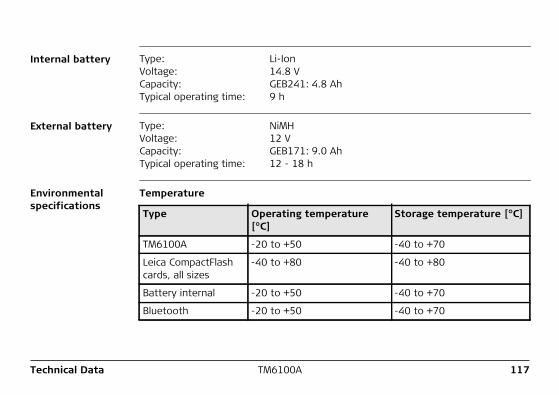
Technical Data TM6100A 117
Internal battery Type: Li-IonVoltage: 14.8 VCapacity: GEB241: 4.8 AhTypical operating time: 9 h
External battery Type: NiMHVoltage: 12 VCapacity: GEB171: 9.0 AhTypical operating time: 12 - 18 h
Environmental specifications
Temperature
Type Operating temperature [°C]
Storage temperature [°C]
TM6100A -20 to +50 -40 to +70
Leica CompactFlash cards, all sizes
-40 to +80 -40 to +80
Battery internal -20 to +50 -40 to +70
Bluetooth -20 to +50 -40 to +70
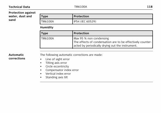
118TM6100ATechnical Data
Protection against water, dust and sand
Type Protection
TM6100A IP54 (IEC 60529)
Humidity
Type Protection
TM6100A Max 95 % non condensingThe effects of condensation are to be effectively counter-acted by periodically drying out the instrument.
Automatic corrections
The following automatic corrections are made:• Line of sight error• Tilting axis error• Circle eccentricity• Compensator index error• Vertical index error• Standing axis tilt

International Limited Warranty, Soft-ware License Agreement
TM6100A 119
8 International Limited Warranty, Software License Agreement
International Limited Warranty
This product is subject to the terms and conditions set out in the International Limited Warranty which you can download from the Leica Geosystems home page at http://www.leica-geosystems.com/internationalwarranty or collect from your Leica Geosystems distributor.
The foregoing warranty is exclusive and is in lieu of all other warranties, terms or conditions, express or implied, either in fact or by operation of law, statutory or otherwise, including warranties, terms or conditions of merchantability, fitness for a particular purpose, satisfactory quality and non-infringement, all of which are expressly disclaimed.
Software License Agreement
This product contains software that is preinstalled on the product, or that is supplied to you on a data carrier medium, or that can be downloaded by you online pursuant to prior authorization from Leica Geosystems. Such software is protected by copy-right and other laws and its use is defined and regulated by the Leica Geosystems Software License Agreement, which covers aspects such as, but not limited to, Scope of the License, Warranty, Intellectual Property Rights, Limitation of Liability, Exclusion of other Assurances, Governing Law and Place of Jurisdiction. Please make sure, that at any time you fully comply with the terms and conditions of the Leica Geosystems Software License Agreement.
120TM6100AInternational Limited Warranty, Soft-ware License Agreement
Such agreement is provided together with all products and can also be referred to and downloaded at the Leica Geosystems home page at http://www.leica-geosys-tems.com/swlicense or collected from your Leica Geosystems distributor.
You must not install or use the software unless you have read and accepted the terms and conditions of the Leica Geosystems Software License Agreement. Installa-tion or use of the software or any part thereof, is deemed to be an acceptance of all the terms and conditions of such license agreement. If you do not agree to all or some of the terms of such license agreement, you may not download, install or use the software and you must return the unused software together with its accompa-nying documentation and the purchase receipt to the dealer from whom you purchased the product within ten (10) days of purchase to obtain a full refund of the purchase price.
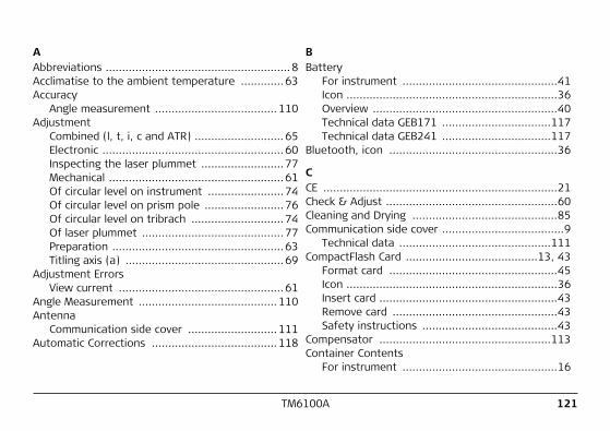
TM6100A 121
AAbbreviations ........................................................8Acclimatise to the ambient temperature .............63Accuracy
Angle measurement .....................................110Adjustment
Combined (l, t, i, c and ATR) ...........................65Electronic .......................................................60Inspecting the laser plummet .........................77Mechanical .....................................................61Of circular level on instrument .......................74Of circular level on prism pole ........................76Of circular level on tribrach ............................74Of laser plummet ...........................................77Preparation ....................................................63Titling axis (a) ................................................69
Adjustment ErrorsView current ..................................................61
Angle Measurement ..........................................110Antenna
Communication side cover ...........................111Automatic Corrections ......................................118
BBattery
For instrument ...............................................41Icon ................................................................36Overview ........................................................40Technical data GEB171 .................................117Technical data GEB241 .................................117
Bluetooth, icon ...................................................36
CCE .......................................................................21Check & Adjust ....................................................60Cleaning and Drying ............................................85Communication side cover .....................................9
Technical data ..............................................111CompactFlash Card ........................................13, 43
Format card ...................................................45Icon ................................................................36Insert card ......................................................43Remove card ..................................................43Safety instructions .........................................43
Compensator ....................................................113Container Contents
For instrument ...............................................16
122TM6100A
Control unit ......................................................114Conversion, data conversion ...............................14Corrections
Automatic ....................................................118
DData Conversion .................................................13Data Storage ......................................................13Dimensions
Of instrument ..............................................115Documentation .....................................................4Drive
OMNI .............................................................14Drives ...............................................................116
EEdit
Value in input field .........................................31Electromagnetic Compatibility EMC ....................104Electronic Adjustment .........................................60ENTER .................................................................22Environmental Specifications .............................117ESC .....................................................................21
FFCC Statement ..................................................107Frequency Band
Communication side cover ............................111
GGeoC++ Software Development Kit ......................12GUS29 .................................................................19
HHazards of Use ....................................................93
IIcons
Overview ........................................................35Instrument
Dimensions ..................................................115Ports ............................................................114Technical data ..............................................112Turn on and turn off ......................................29Weight .........................................................115
Instrument Components ......................................17Instrument Models ..............................................10Instrument Setup
Conventional ..................................................37
TM6100A 123
Intended Use ......................................................89Internal Memory .................................................13Internal memory, icon .........................................36Internal target ....................................................19
KKeyboard ......................................................20, 29
Locking and unlocking ....................................29Operating principles .......................................29
Keys ...................................................................21Keys, Alphanumeric .............................................21Keys, Arrow ........................................................22Keys, Combinations ............................................23Keys, Function ....................................................22Keys, Hot ............................................................21
LLaser Classification .............................................99
Electronic Guide Light EGL ............................101Integrated Distancer, Invisible Laser .............100Laser Plummet .............................................101PowerSearch PS ...........................................101
Laser PlummetAdjustment ....................................................77Technical data ..............................................116
LEICA Geo Office LGO Tools, description ..........8, 10Level ...........................................................23, 113Lights ..................................................................23Lock, keyboard ....................................................29
MMaintenance .......................................................87Manual
Validity of user manual .....................................3Mechanical Adjustment ........................................61Menu, selecting from a ........................................30
OOMNI drive ..........................................................14ON ......................................................................21Operation .........................................................116Output Power
Communication side cover ............................111
PPage, selecting from a .........................................30Pages down ........................................................23Pages up .............................................................23Ports .................................................................114Power Supply ......................................................15
124TM6100A
PowerSearch PS ................................................111Precise Measurements ........................................61PROG ..................................................................21
QQuick coding, icon ...............................................36Quick settings .....................................................23
RRaw data transfer to LGO Tools ..........................14Recording .........................................................116Reflectors .........................................................118Responsibilities ...................................................92
SSafety Directions ................................................88Screen ................................................................27Scroll bar, description .........................................28Service of tripod .................................................79Setup
Conventional ..................................................37SHIFT ............................................................22, 36Software
Application programs .....................................12Customised application programs ...................12
Language software .........................................11Software type ................................................11Software upload .............................................12System software ............................................11
Software Concept ...............................................11Storage ...............................................................84Survey Application ...............................................46System Concept ..................................................11
TTechnical Data ...................................................110Telescope ..........................................................112Telescope Protection Cushion ..............................82Temperature
Battery InternalOperating ................................................117Storage ...................................................117
BluetoothOperating ................................................117Storage ...................................................117
CompactFlash CardOperating ................................................117Storage ...................................................117
Instrument
TM6100A 125
Operating ...............................................117Storage ...................................................117
Terminology ..........................................................8T-LINK .................................................................52Touch Screen, operating principles ......................29Transfer raw data to LGO Tools ..........................14Transport ............................................................82Tripod, service of ................................................79
UUnlock, keyboard ................................................29USB Download Cable ...........................................53USER ...................................................................21User Interface .....................................................20
VValue, edit in input field ......................................31View Current Adjustment Errors ..........................61
WWeight
Of instrument ..............................................115
YY-Cable ...............................................................53

Total Quality Management: Our commitment to total customer satisfaction.
Leica Geosystems AG, Heerbrugg, Switzerland, has been certified as being equipped with a quality system which meets the International Standards of Quality Management and Quality Systems (ISO standard 9001) and Environmental Management Systems (ISO standard 14001).
Ask your local Leica Geosystems dealer for more information about our TQM program.
7813
66-1
.0.2
enO
rigin
al t
ext
Prin
ted
in S
witz
erla
nd ©
200
9 Le
ica
Geo
syst
ems
AG, H
eerb
rugg
, Sw
itzer
land
Leica Geosystems AGHeinrich-Wild-StrasseCH-9435 HeerbruggSwitzerlandPhone +41 71 727 31 31www.leica-geosystems.com