Embed Size (px)
Citation preview
1
Chemical Oxidation Technologies:Lessons Learned & Best Practices
fromExpert Perspectives
Jointly prepared & presented by –
“The experts”Cindy Schreier, Ph.D., PRIMA Environmental, Inc.Larry Kinsman, ORIN Remediation Technologies
In collaboration with -Mike Martinson, Delta Consultants
James F. Cuthbertson, P.E., Delta Consultants
2
Today’s Agenda
Chemical Oxidation Technologies: • Overview: Chemistries, HSE Issues, CoC Applications• Site Characterization• Bench-Scale Testing• Pilot-Scale Testing• Full-Scale Systems• Monitoring Chemox Remediation• Regulatory Concerns and Issues• Case Histories: Bench-, Pilot-, and Full-Scale• Additional References• Your Questions and Discussion
3
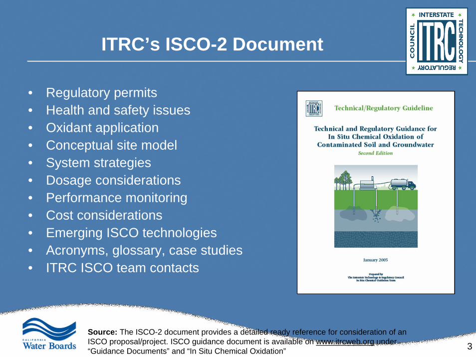
ITRC’s ISCO-2 Document
• Regulatory permits• Health and safety issues• Oxidant application• Conceptual site model• System strategies• Dosage considerations• Performance monitoring• Cost considerations• Emerging ISCO technologies• Acronyms, glossary, case studies• ITRC ISCO team contacts
Source: The ISCO-2 document provides a detailed ready reference for consideration of an ISCO proposal/project. ISCO guidance document is available on www.itrcweb.org under “Guidance Documents” and “In Situ Chemical Oxidation”
4
Chemical Oxidation OverviewChemical Oxidation = Chemox
Applicability to Petroleum Hydrocarbon Contaminant Concentrations
– Potentially can be applied to site-specific conditions:
• Ground water & soil at lower ppm concentrations– May be effective, but other technologies may be more cost-effective
• Ground water & soil at higher ppm concentrations– “Sweet spot” for application where the relatively short duration of
Chemox can outperform other longer-term & costly O&M technologies
• Soil-sorbed residual LNAPL– May be effective with a correspondingly high oxidant dosage
• Mobile LNAPL (free-phase petroleum product)– An aggressive application for Chemox with the highest oxidant dosages– Mandates better than average site characterization– Flawless Chemox process controls are critical to control reactions
5
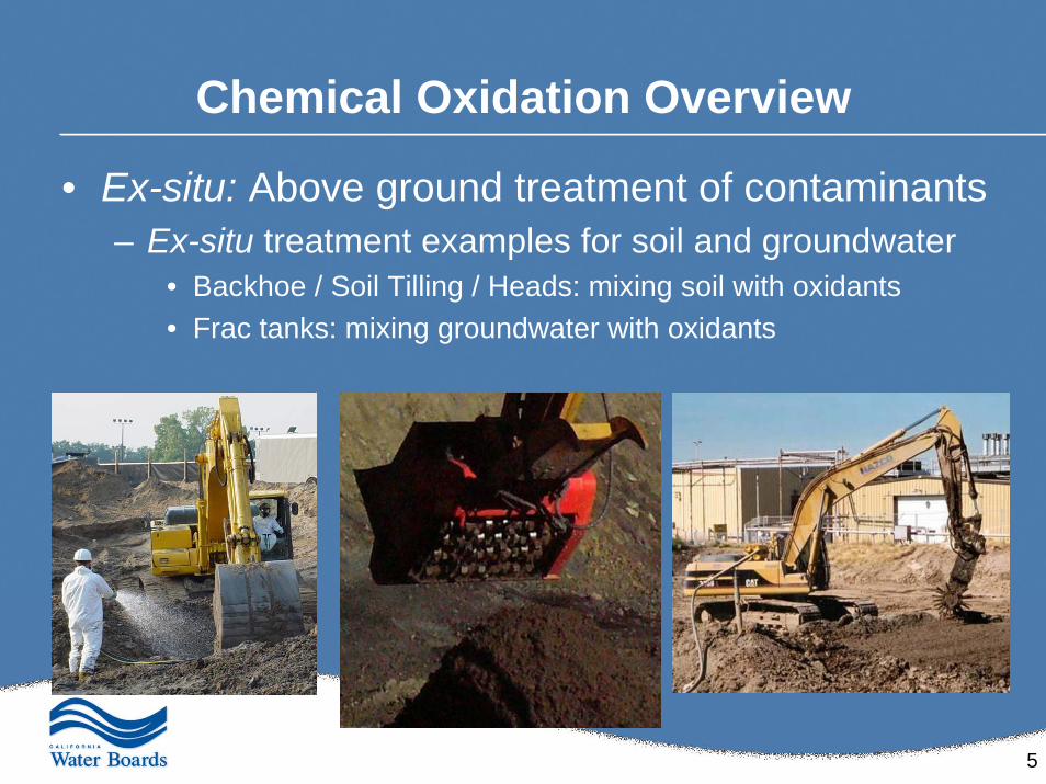
Chemical Oxidation Overview
• Ex-situ: Above ground treatment of contaminants– Ex-situ treatment examples for soil and groundwater
• Backhoe / Soil Tilling / Heads: mixing soil with oxidants• Frac tanks: mixing groundwater with oxidants
6
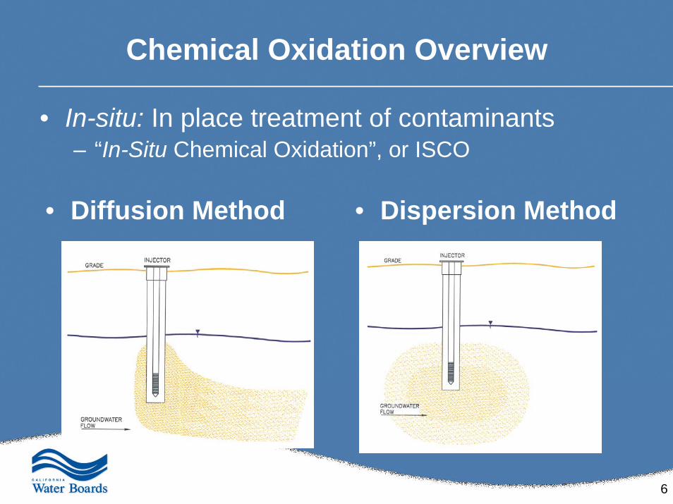
Chemical Oxidation Overview
• In-situ: In place treatment of contaminants– “In-Situ Chemical Oxidation”, or ISCO
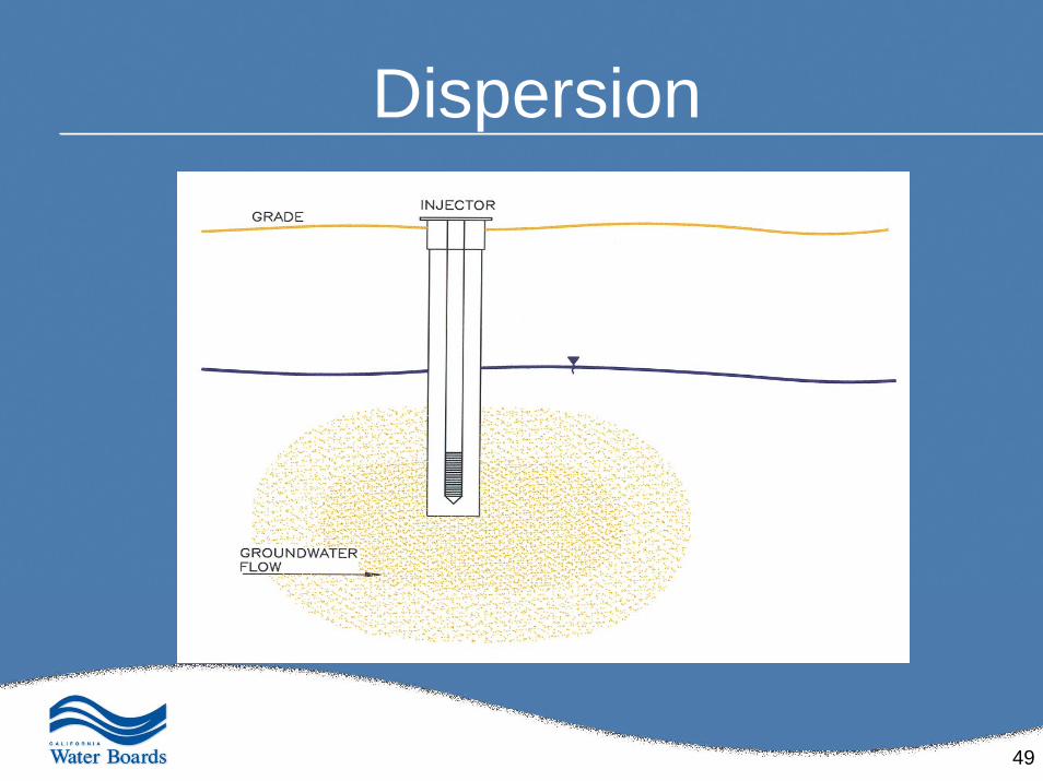
• Diffusion Method • Dispersion Method
7
Best Lithologies for Injection Technologies• Homogeneous well-sorted, medium- to coarse-grained sand is
the best lithology– high permeability and low hydrostatic pressure
• Fractured bedrock can be injected into through temporary, drilled points– However, flow rate, volume and treatment effectiveness need to be
monitored closely to ensure that the micro-fractures within the bedrock don’t become clogged or congested
• Overlying clay layers increase the probability of success– Because they form a seal, or cap, that prevents treatment chemistry
from exuding through the surface and improves horizontal dispersion
• Any lithology can be injected into…– However, the more heterogeneous the formation is and the more clayey
the site is, the harder it is to predict and direct exactly where the reagents are delivered
8
Oxidizing Chemistries:Health, Safety & Environment (HSE) Concerns
• Read & understand material safety datasheets (MSDS) prior to materials handling (reference MSDS websites as needed)
• Potential hazard risks to mitigate and avoid:– extreme contact risk, especially to eyes
• Personal protective equipment (PPE) is a must• Readily available eyewash / shower
– inhalation and dermal contact
• Ensure oxidants compatibility with equipment and materials
• Store and protect oxidants (heat/cold & sun/rain, as appropriate)
• Develop site-specific Health and Safety Plans (HASPs) in accordance with 29 CFR 1910.120 guidance
• Enforce HASP requirements for everyone on-site!
9
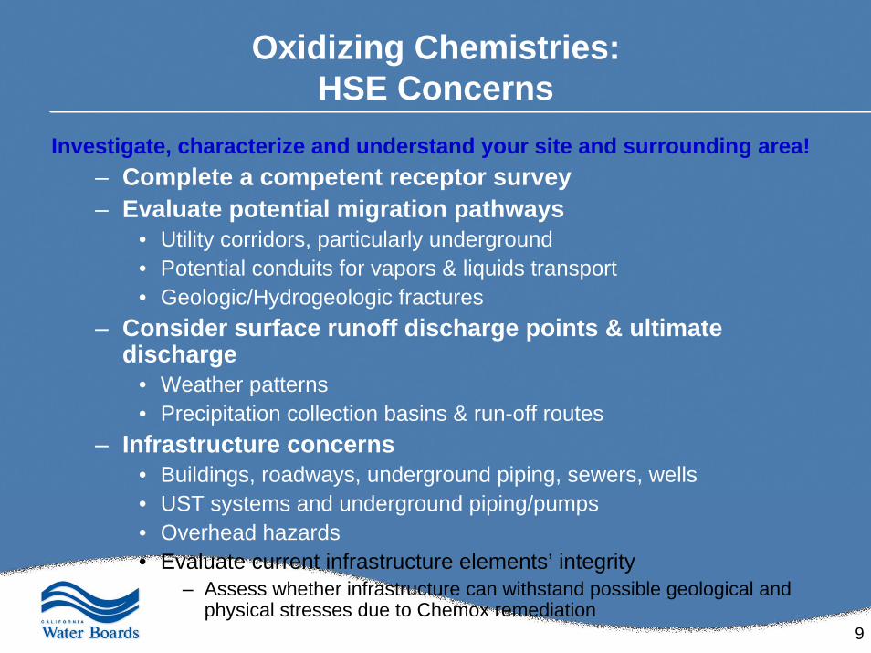
Oxidizing Chemistries:HSE Concerns
Investigate, characterize and understand your site and surrounding area!– Complete a competent receptor survey – Evaluate potential migration pathways
• Utility corridors, particularly underground• Potential conduits for vapors & liquids transport• Geologic/Hydrogeologic fractures
– Consider surface runoff discharge points & ultimate discharge
• Weather patterns• Precipitation collection basins & run-off routes
– Infrastructure concerns• Buildings, roadways, underground piping, sewers, wells• UST systems and underground piping/pumps• Overhead hazards• Evaluate current infrastructure elements’ integrity
– Assess whether infrastructure can withstand possible geological and physical stresses due to Chemox remediation
10
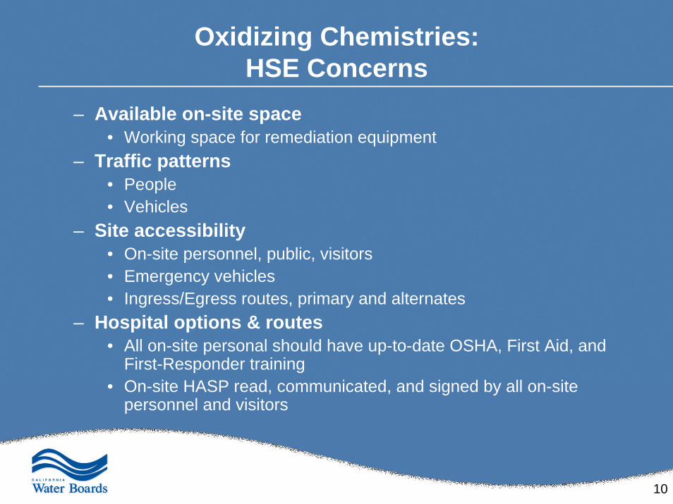
Oxidizing Chemistries:HSE Concerns
– Available on-site space• Working space for remediation equipment
– Traffic patterns• People• Vehicles
– Site accessibility• On-site personnel, public, visitors• Emergency vehicles• Ingress/Egress routes, primary and alternates
– Hospital options & routes• All on-site personal should have up-to-date OSHA, First Aid, and
First-Responder training• On-site HASP read, communicated, and signed by all on-site
personnel and visitors
11
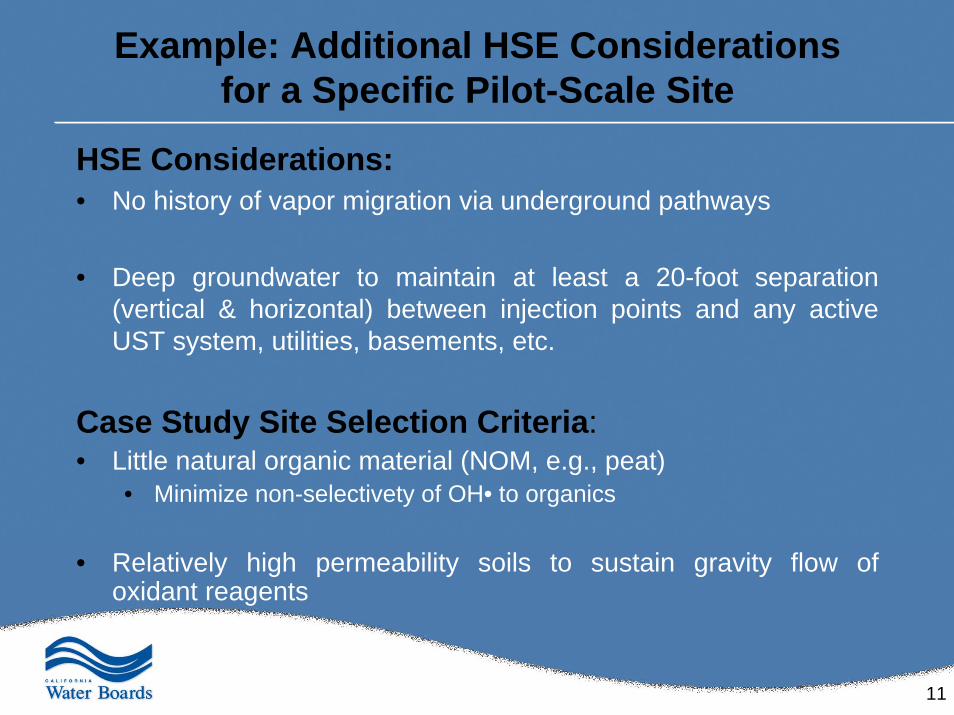
Example: Additional HSE Considerations for a Specific Pilot-Scale Site
HSE Considerations:• No history of vapor migration via underground pathways
• Deep groundwater to maintain at least a 20-foot separation (vertical & horizontal) between injection points and any active UST system, utilities, basements, etc.
Case Study Site Selection Criteria:• Little natural organic material (NOM, e.g., peat)
• Minimize non-selectivety of OH• to organics
• Relatively high permeability soils to sustain gravity flow of oxidant reagents
12
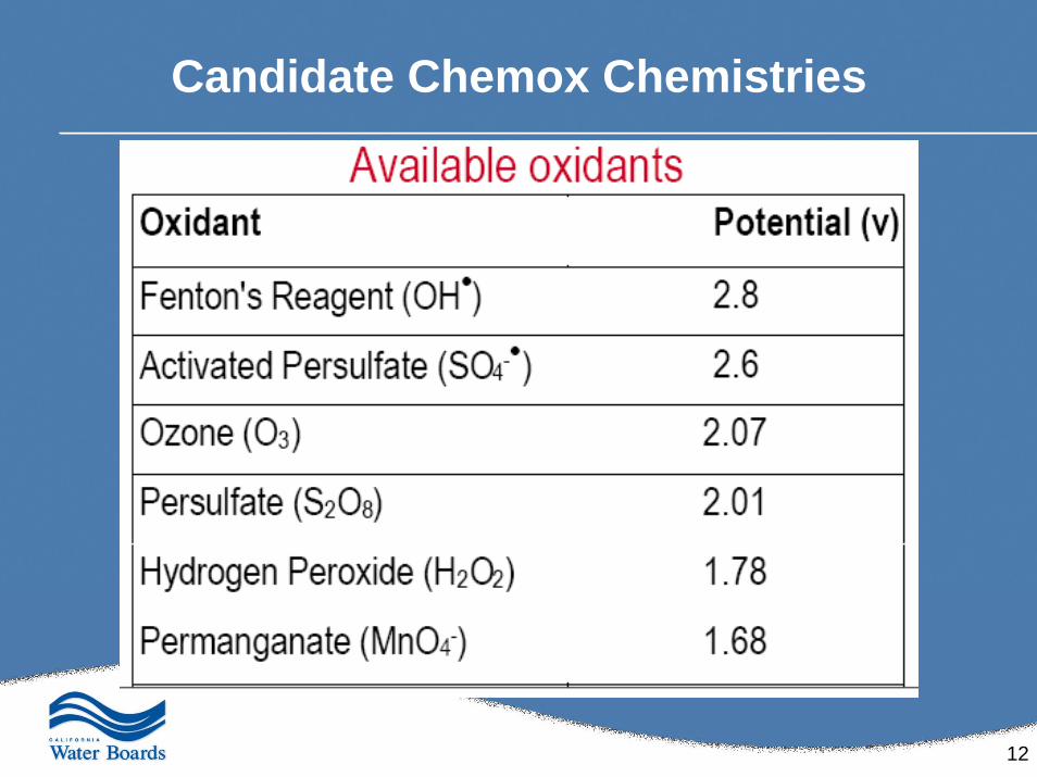
Candidate Chemox Chemistries
13
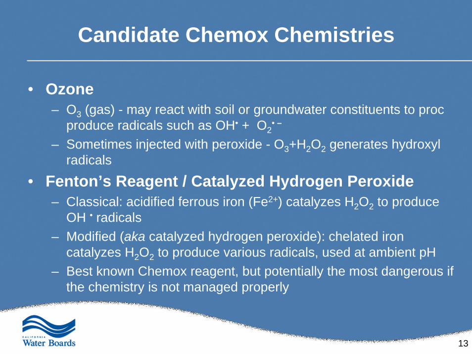
Candidate Chemox Chemistries
• Ozone– O3 (gas) - may react with soil or groundwater constituents to proc
produce radicals such as OH• + O2• –
– Sometimes injected with peroxide - O3+H2O2 generates hydroxyl radicals
• Fenton’s Reagent / Catalyzed Hydrogen Peroxide– Classical: acidified ferrous iron (Fe2+) catalyzes H2O2 to produce
OH • radicals– Modified (aka catalyzed hydrogen peroxide): chelated iron
catalyzes H2O2 to produce various radicals, used at ambient pH– Best known Chemox reagent, but potentially the most dangerous if
the chemistry is not managed properly
14
Candidate Chemox Chemistries
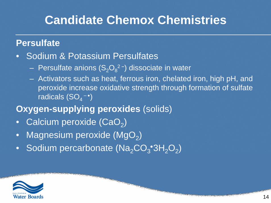
Persulfate• Sodium & Potassium Persulfates
– Persulfate anions (S2O82 –) dissociate in water
– Activators such as heat, ferrous iron, chelated iron, high pH, and peroxide increase oxidative strength through formation of sulfate radicals (SO4
– •)
Oxygen-supplying peroxides (solids)• Calcium peroxide (CaO2)• Magnesium peroxide (MgO2)• Sodium percarbonate (Na2CO3
•3H2O2)
15
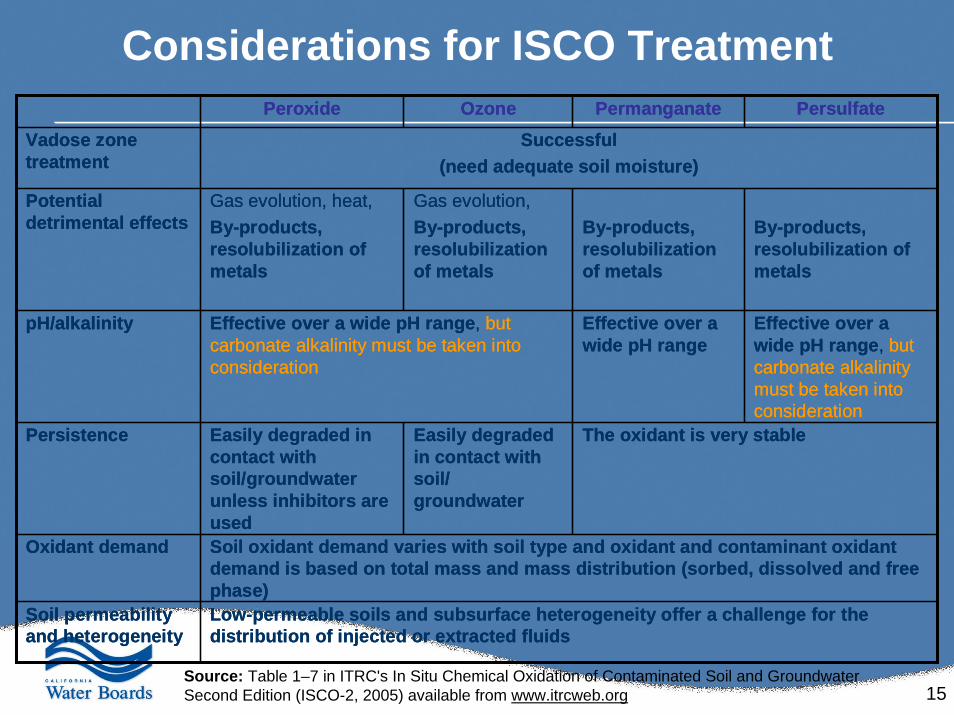
Considerations for ISCO Treatment
Low-permeable soils and subsurface heterogeneity offer a challenge for the distribution of injected or extracted fluids
Soil permeability and heterogeneity
Soil oxidant demand varies with soil type and oxidant and contaminant oxidant demand is based on total mass and mass distribution (sorbed, dissolved and free phase)
Oxidant demand
The oxidant is very stableEasily degraded in contact with soil/ groundwater
Easily degraded in contact with soil/groundwater unless inhibitors are used
Persistence
Effective over a wide pH range, but carbonate alkalinity must be taken into consideration
Effective over a wide pH range
Effective over a wide pH range, but carbonate alkalinity must be taken into consideration
pH/alkalinity
By-products, resolubilization of metals
By-products, resolubilization of metals
Gas evolution, By-products, resolubilization of metals
Gas evolution, heat, By-products, resolubilization of metals
Potential detrimental effects
Successful(need adequate soil moisture)
Vadose zone treatment
PersulfatePermanganateOzonePeroxide
Source: Table 1–7 in ITRC's In Situ Chemical Oxidation of Contaminated Soil and GroundwaterSecond Edition (ISCO-2, 2005) available from www.itrcweb.org
16
Geochemical Considerations
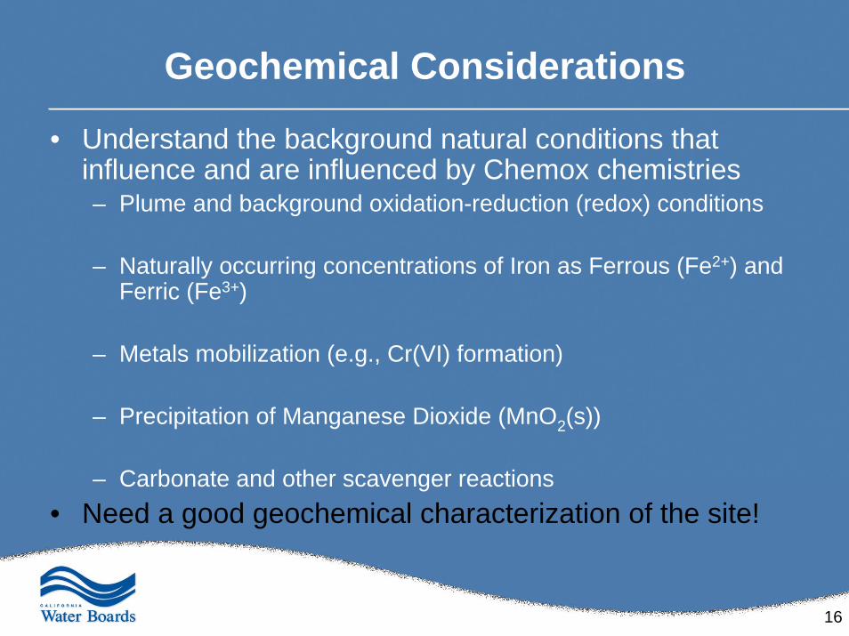
• Understand the background natural conditions that influence and are influenced by Chemox chemistries– Plume and background oxidation-reduction (redox) conditions
– Naturally occurring concentrations of Iron as Ferrous (Fe2+) and Ferric (Fe3+)
– Metals mobilization (e.g., Cr(VI) formation)
– Precipitation of Manganese Dioxide (MnO2(s))
– Carbonate and other scavenger reactions• Need a good geochemical characterization of the site!
17
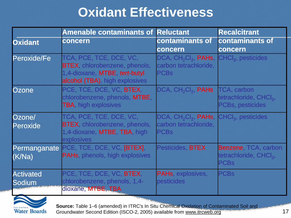
Oxidant Effectiveness
PCBs PAHs, explosives, pesticides
PCE, TCE, DCE, VC, BTEX, chlorobenzene, phenols, 1,4-dioxane, MTBE, TBA
Activated Sodium Persulfate
Benzene, TCA, carbon tetrachloride, CHCl3, PCBs
Pesticides, BTEXPCE, TCE, DCE, VC, [BTEX], PAHs, phenols, high explosives
Permanganate (K/Na)
CHCl3, pesticides DCA, CH2Cl2, PAHs, carbon tetrachloride, PCBs
TCA, PCE, TCE, DCE, VC, BTEX, chlorobenzene, phenols, 1,4-dioxane, MTBE, TBA, high explosives
Ozone/ Peroxide
TCA, carbon tetrachloride, CHCl3, PCBs, pesticides
DCA, CH2Cl2, PAHsPCE, TCE, DCE, VC, BTEX, chlorobenzene, phenols, MTBE, TBA, high explosives
Ozone
CHCl3, pesticides DCA, CH2Cl2, PAHs, carbon tetrachloride, PCBs
TCA, PCE, TCE, DCE, VC, BTEX, chlorobenzene, phenols, 1,4-dioxane, MTBE, tert-butylalcohol (TBA), high explosives
Peroxide/Fe
Recalcitrant contaminants of concern
Reluctant contaminants of concern
Amenable contaminants of concernOxidant
Source: Table 1–6 (amended) in ITRC's In Situ Chemical Oxidation of Contaminated Soil and Groundwater Second Edition (ISCO-2, 2005) available from www.itrcweb.org
18
Site Characterization
19
Typical Site Management Problems
• Site complexities – Complicated hydrogeology – Multiple contaminants of concern (CoCs) – Multiple receptors/pathways
• Multiple phases of investigation and remediation • Deliverables that are not stand-alone documents • Changes in consultants • Changes in regulatory oversight • Case load
20
Common Outcome
• An abundance of data • Lack of clarity concerning the major site issues and how
to move the site toward closure
Suggestion• Direct the Responsible Party (RP) to complete a Site
Conceptual Model
21
Site Conceptual Model (SCM)• EPA: A representation of site conditions developed using
readily available (existing) data that illustrates the relationship between contaminants, retention/transport media, and receptors.
– EPA. November 2000. Using the Conceptual Site Model to Select Performance Standards and Develop Data Quality Objectives in the CAS.
• SCM’s Purpose:– Organize information already known about the site – Help identify additional information that must be obtained – Suggest when site characterization is complete
• If the SCM is not likely to significantly change upon collection of additional information, the existing data are adequate
22
Developing the Site Conceptual Model• Subsurface geology• Site topography• Aquifer geochemistry (particularly important to Chemox)
– Soil and groundwater data• such as pH, temperature, conductivity, dissolved oxygen, ORP
– Monitored natural attenuation terminal electron acceptor / donorparameters
• Fe+3, Fe+2, Mn+2, NO3, SO4, sulfide, chloride, alkalinity, TOC, CO2, CH4, dissolved-H2
• Identification of major migration pathways for CoCs• Direction / gradient / velocity of groundwater flow• Surface and subsurface structures• Underground utilities• Surface water features / uses, and potential receptors in
the area
23
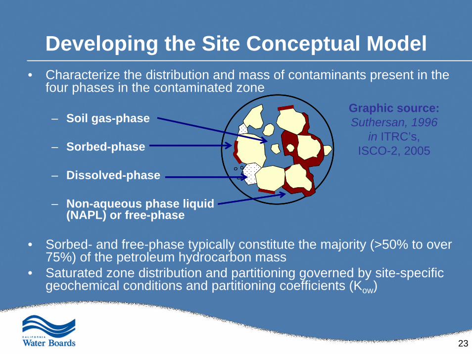
Developing the Site Conceptual Model• Characterize the distribution and mass of contaminants present in the
four phases in the contaminated zone
– Soil gas-phase
– Sorbed-phase
– Dissolved-phase
– Non-aqueous phase liquid (NAPL) or free-phase
• Sorbed- and free-phase typically constitute the majority (>50% to over 75%) of the petroleum hydrocarbon mass
• Saturated zone distribution and partitioning governed by site-specific geochemical conditions and partitioning coefficients (Kow)
Graphic source:Suthersan, 1996
in ITRC’s, ISCO-2, 2005
24
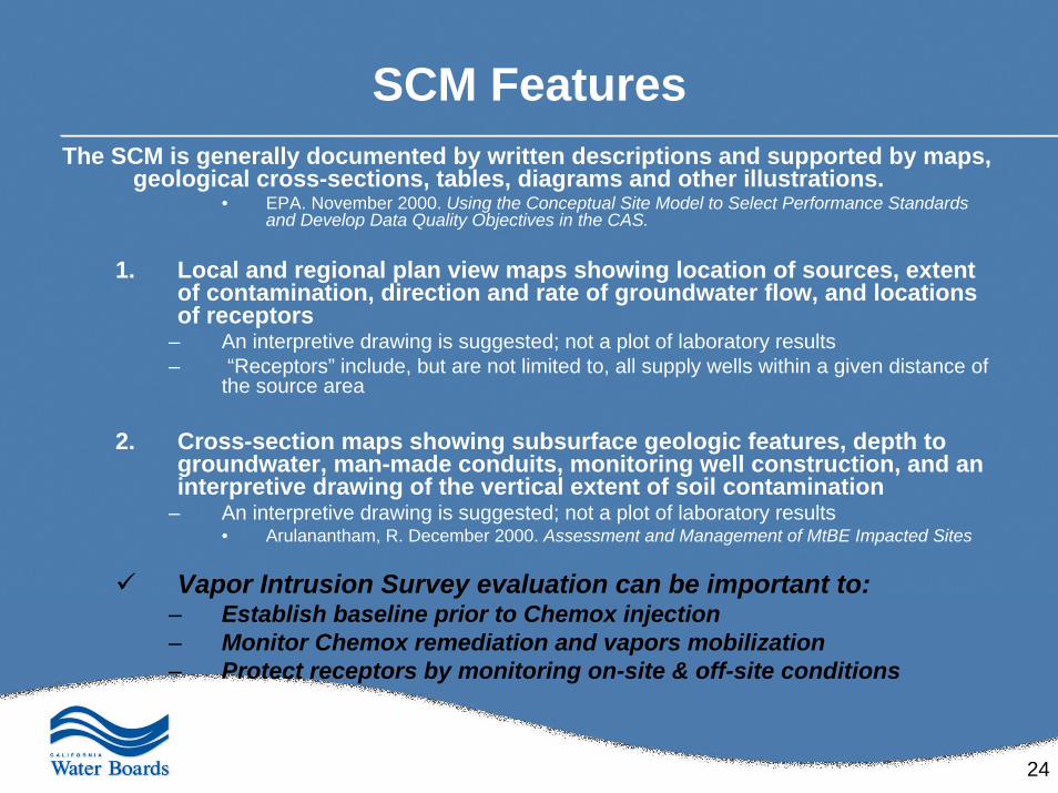
SCM FeaturesThe SCM is generally documented by written descriptions and supported by maps,
geological cross-sections, tables, diagrams and other illustrations.• EPA. November 2000. Using the Conceptual Site Model to Select Performance Standards
and Develop Data Quality Objectives in the CAS.
1. Local and regional plan view maps showing location of sources, extent of contamination, direction and rate of groundwater flow, and locations of receptors
– An interpretive drawing is suggested; not a plot of laboratory results– “Receptors” include, but are not limited to, all supply wells within a given distance of
the source area
2. Cross-section maps showing subsurface geologic features, depth to groundwater, man-made conduits, monitoring well construction, and an interpretive drawing of the vertical extent of soil contamination
– An interpretive drawing is suggested; not a plot of laboratory results• Arulanantham, R. December 2000. Assessment and Management of MtBE Impacted Sites
Vapor Intrusion Survey evaluation can be important to:– Establish baseline prior to Chemox injection– Monitor Chemox remediation and vapors mobilization– Protect receptors by monitoring on-site & off-site conditions
25
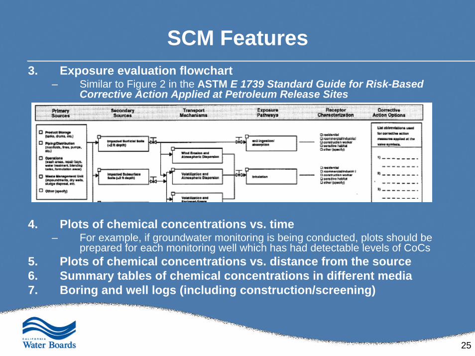
SCM Features3. Exposure evaluation flowchart
– Similar to Figure 2 in the ASTM E 1739 Standard Guide for Risk-Based Corrective Action Applied at Petroleum Release Sites
4. Plots of chemical concentrations vs. time – For example, if groundwater monitoring is being conducted, plots should be
prepared for each monitoring well which has had detectable levels of CoCs5. Plots of chemical concentrations vs. distance from the source 6. Summary tables of chemical concentrations in different media 7. Boring and well logs (including construction/screening)
26
Chemox’s Specific Project Needs• Remediation objectives and CoC’s clean-up goals
• Mass & distribution of free-phase
• Length, width and vertical extent of contamination– Soil and groundwater data – Depth to groundwater and flow velocity and direction
• Type of lithology and associated density and porosity
• Boring logs and site maps
• Site use: past, present and future
• Location of site utilities and source of water for Chemox use
27
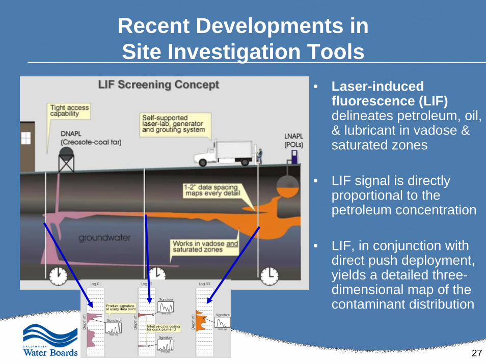
Recent Developments in Site Investigation Tools
• Laser-induced fluorescence (LIF)delineates petroleum, oil, & lubricant in vadose & saturated zones
• LIF signal is directly proportional to the petroleum concentration
• LIF, in conjunction with direct push deployment, yields a detailed three-dimensional map of the contaminant distribution
28
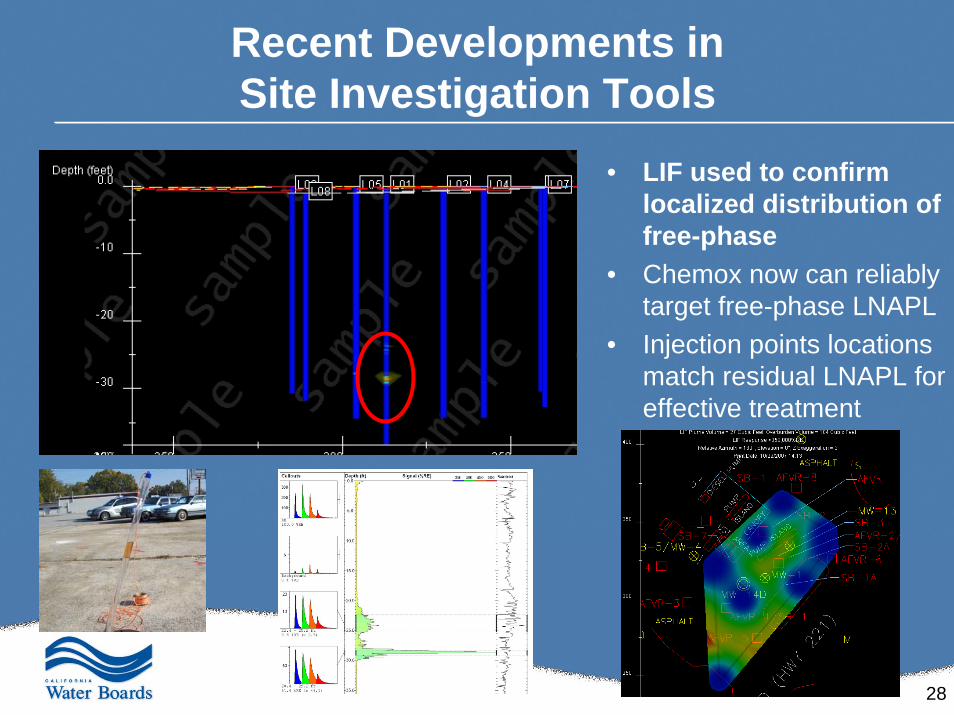
Recent Developments in Site Investigation Tools
• LIF used to confirm localized distribution of free-phase
• Chemox now can reliably target free-phase LNAPL
• Injection points locations match residual LNAPL for effective treatment
29
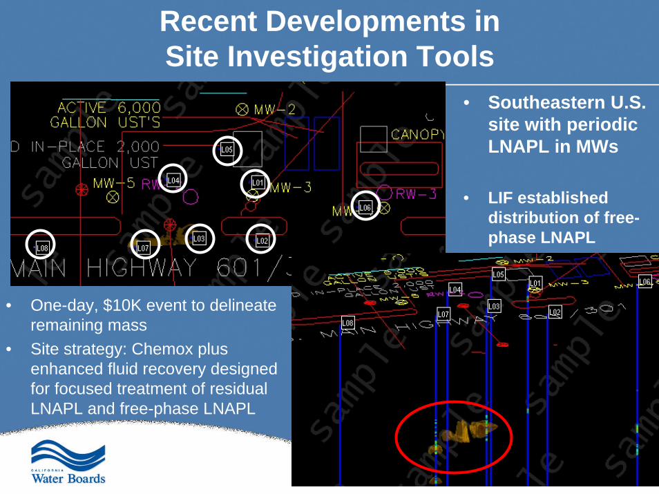
Recent Developments in Site Investigation Tools
• One-day, $10K event to delineate remaining mass
• Site strategy: Chemox plus enhanced fluid recovery designed for focused treatment of residual LNAPL and free-phase LNAPL
• Southeastern U.S. site with periodic LNAPL in MWs
• LIF established distribution of free-phase LNAPL
30
Recent Developments in Site Investigation Tools
31
Summary• SCMs can assist in completing a sound site characterization and
working through common site management problems and issues
• Chemox remediation feasibility testing and remedial action selection utilizes most, if not all, of the information developed for the SCM
• Chemox requires clearly defined site remediation objectives and clean-up goals
And particularly for Chemox applications…• Delineation! Delineation! Delineation!
– Leads to the Right Chemistry– Leads to the Proper Implementation– Gives the Best Possible Chemox Results
32
Bench-Scale Testing
Treatability testing is laboratory testing performed on soil and/or water to provide
information beyond “what is the concentration of the contaminant?”
33
Typical ISCO Bench Test Objectives
• Verify contaminant removal• Estimate oxidant requirement• Assess effect of treatment on secondary water quality
(e.g., bromate, Cr(VI), pH, dissolved iron, mobilization of metals)
• Assess attenuation of secondary parameters
34
COC Removal/Mechanism
• Ozone, Fenton’s reagent– TPH, BTEX, fuel oxygenates generally removed– Removal mostly due to destruction, but some volatilization,
especially for Fenton’s– Acetone typical by-product; occasionally TBA from MTBE
• Activated persulfate– Removal of TPH, BTEX, fuel oxys more variable in PRIMA’s
experience– Effectiveness may depend upon activator used (heat is most
effective, but not always practical)– By-products not common with TPH; occasionally halogenated
intermediates
35
Oxidant Requirements• Calculated – ozone, persulfate
– Chemical equations can be written for specific compounds (egbenzene, MTBE), but not mixtures such as TPH
– Chemical equations assume conversion to CO2
– Calculated values do not account for natural organic matter and non-target compounds
– Calculated values do not account for rapid decomposition of oxidant (ozone, Fenton’s reagent) decompose relatively quickly
• Empirical– Ozone, activated persulfate—measure soil and groundwater
demand– Fenton’s reagent—can’t measure oxidant demand, so measure
longevity of Fenton’s reagent instead
36
Potential Secondary Effects• Bromate
– Formed by ozonation of naturally occurring bromide– Amount formed depends upon amount of ozone applied, but
formation is site-specific
• Cr(VI)– Formed from oxidation of soil chromium – Most common with permanganate, ozone; rare with activated
persulfate or Fenton’s reagent– Amt. formed site-specific depends upon amt. of oxidant applied
• Metals mobilization– Mobilization highly site-specific– Mobilization may occur due to change in pH or presence of
chelating agent associated with oxidant
37
Cr(VI) Attenuation• Most soils have some ability to attenuate Cr(VI)
– Organic matter reduces Cr(VI) to Cr(III)– Reduced mineral species can convert Cr(VI) to Cr(III)– Microbial activity can generate reducing conditions [i.e., from
sulfide, nitrite, or other species capable of supplying electrons to Cr(VI) ]
• ISCO may affect ability of soil to attenuation Cr(VI)– ISCO destroys many compounds that could attenuate Cr(VI)– Downgradient soil may still readily attenuate Cr(VI)
38
Test Procedures• Test design depends upon test goals• Sources of tests include
– PRIMA Environmental– Clients/regulators/other stakeholders– Scientific literature
• Common protocols (PRIMA)– Batch tests (column tests usually not practical)– Use soil (composited) and groundwater (composited)– 1:5 soil to liquid ratio (necessary in order to have enough water
for post-treatment analyses)– Room temperature (18-25°C)
39
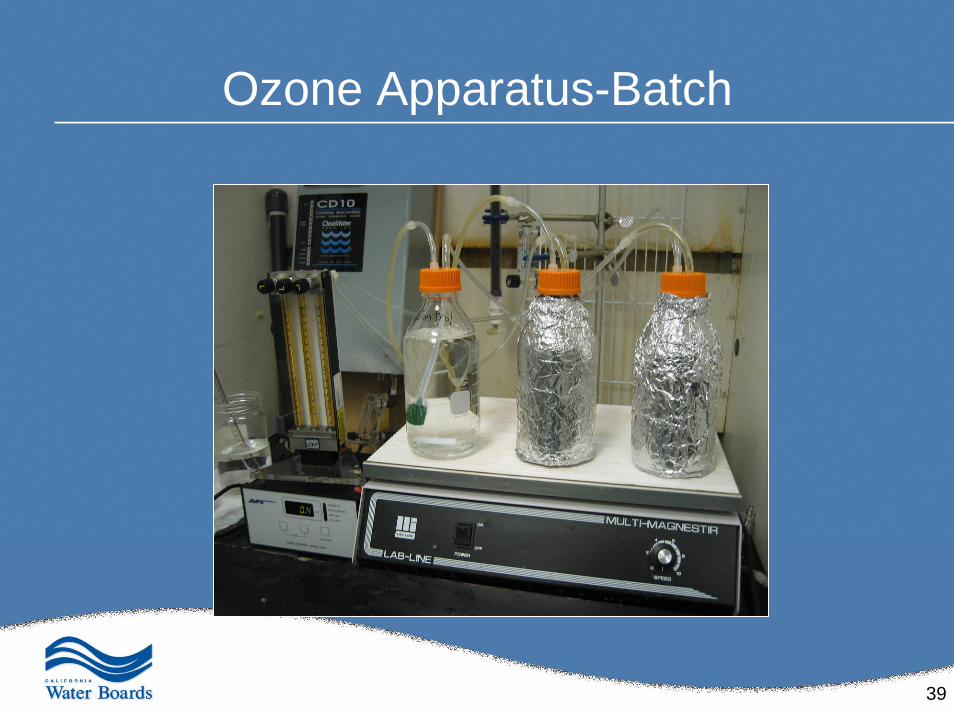
Ozone Apparatus-Batch
40
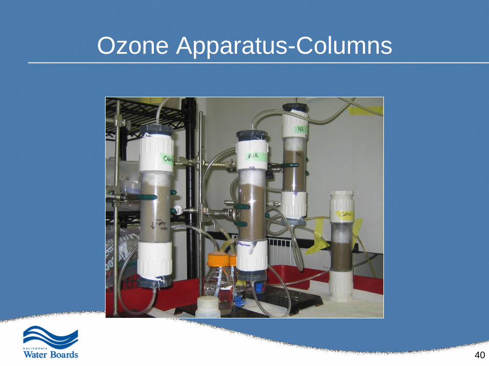
Ozone Apparatus-Columns
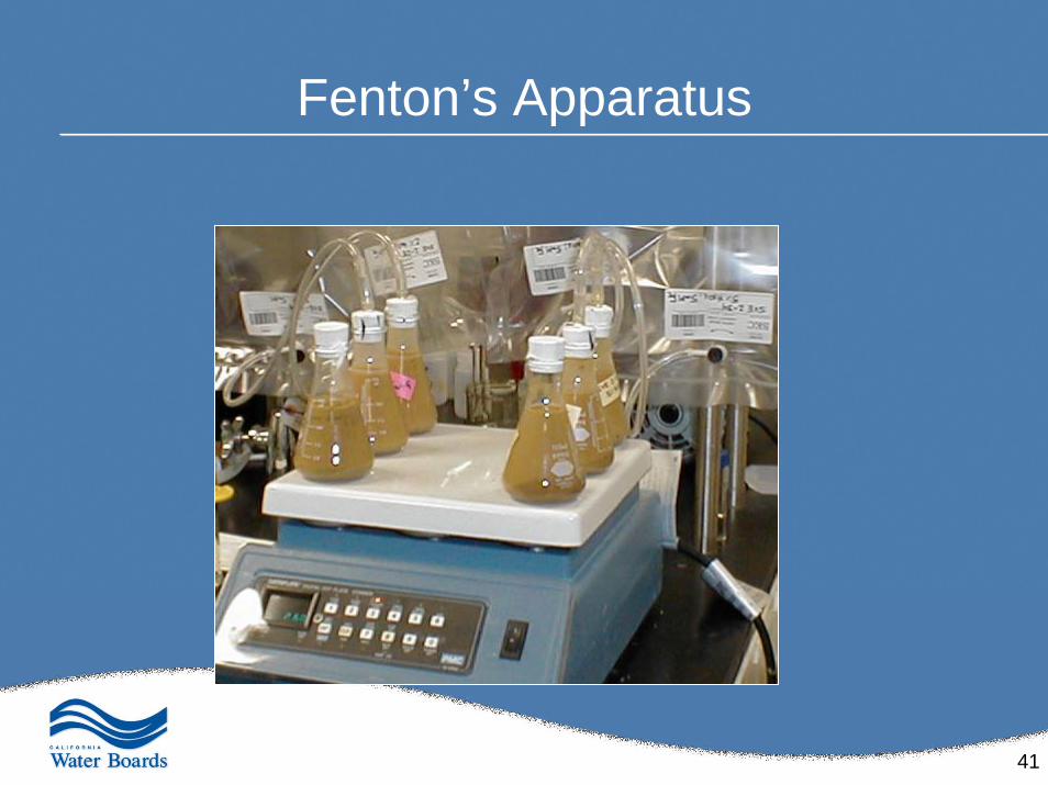
41
Fenton’s Apparatus
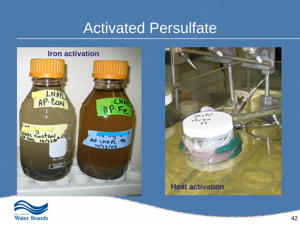
42
Activated PersulfateIron activation
Heat activation
43
What Lab Testing Can Do
• Determine whether a specific oxidant can destroy site CoCs
• Estimate the amount of reagent required• Identify which secondary effects may potentially
be an issue during field application• Determine whether secondary effects are likely
to be transient (e.g., can Cr(VI) attenuate?)
44
What Lab Testing Can Do—cont’d
• Help troubleshoot field results (e.g., if good removal occurs in lab, poor removal in field may be due to difficulty delivering reagent)
• Provide a better understanding of the site
• Raise the comfort level of stakeholders
45
What Lab Testing Cannot Do
• Perfectly simulate field conditions– Can’t determine exact amount of reagent needed– Can’t predict the exact degree of change in a
secondary parameter– Predict exactly how long secondary effects will last
• Promise perfect results in the field– Applicability of bench test results depends upon how
well test soil / groundwater represents the site – Success of ISCO depends upon skill and experience
of field remediation team
46
Pilot-Scale Testing and Full Scale Implementation
47
Current In-Situ Methodologies
Diffusion method
Dispersion method
48
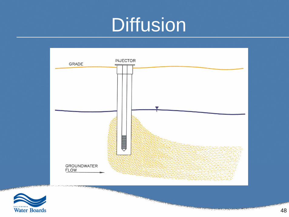
Diffusion
49
Dispersion
50
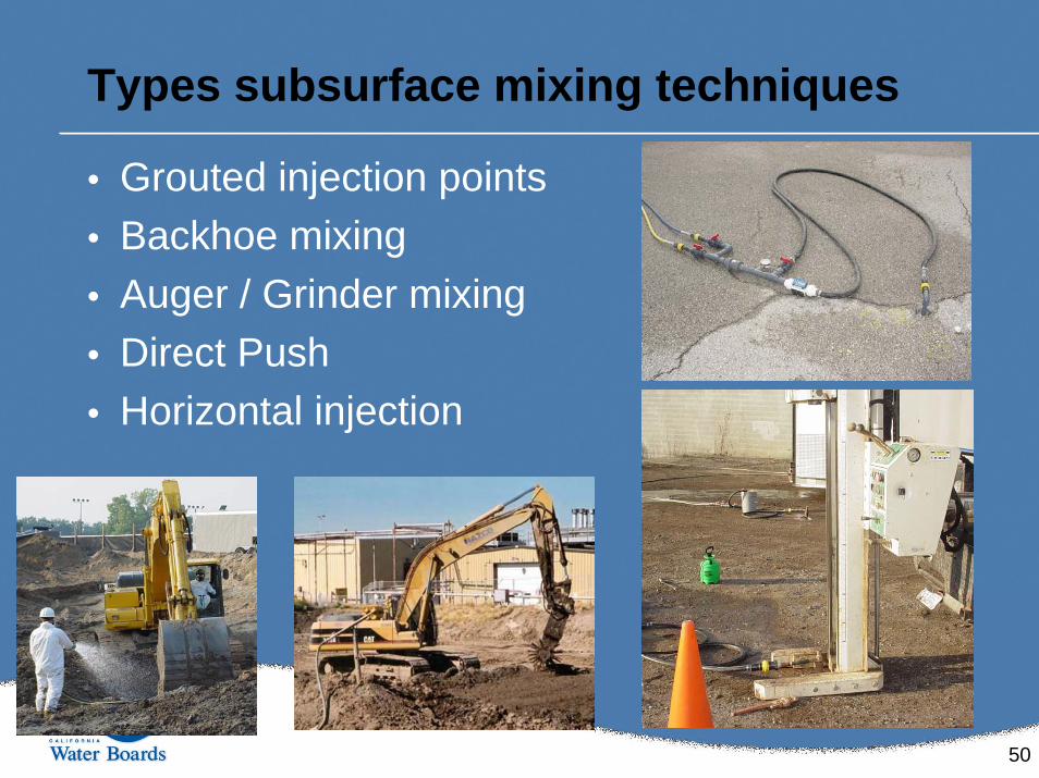
• Grouted injection points• Backhoe mixing • Auger / Grinder mixing• Direct Push• Horizontal injection
Types subsurface mixing techniques
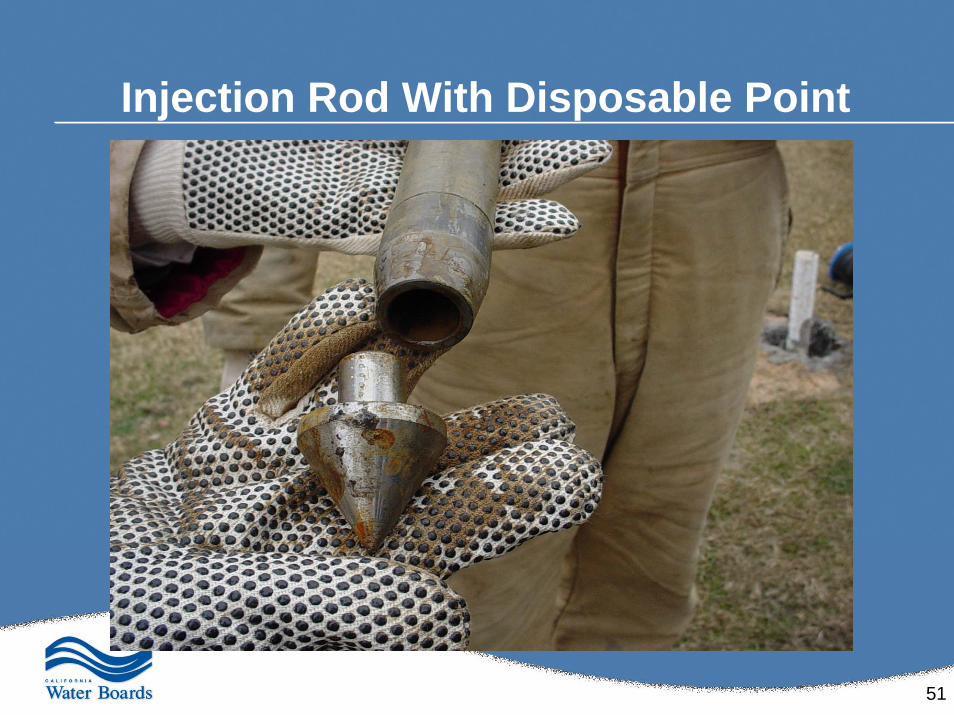
51
Injection Rod With Disposable Point
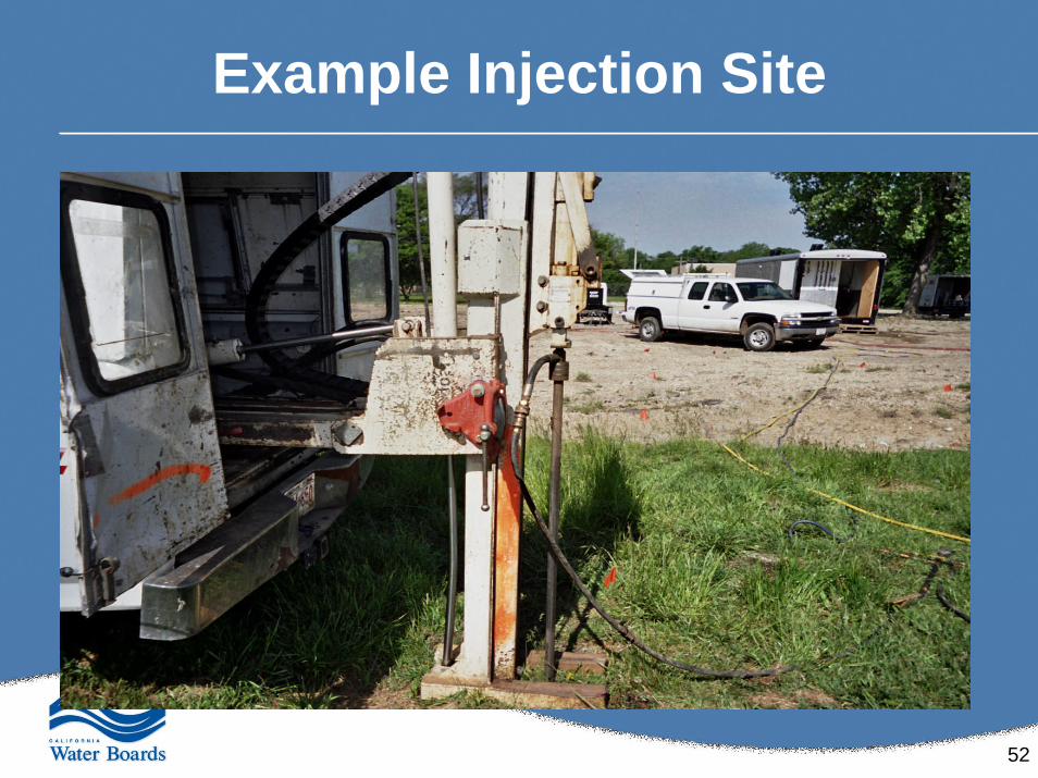
52
Example Injection Site
53
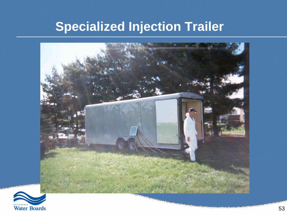
Specialized Injection Trailer
54
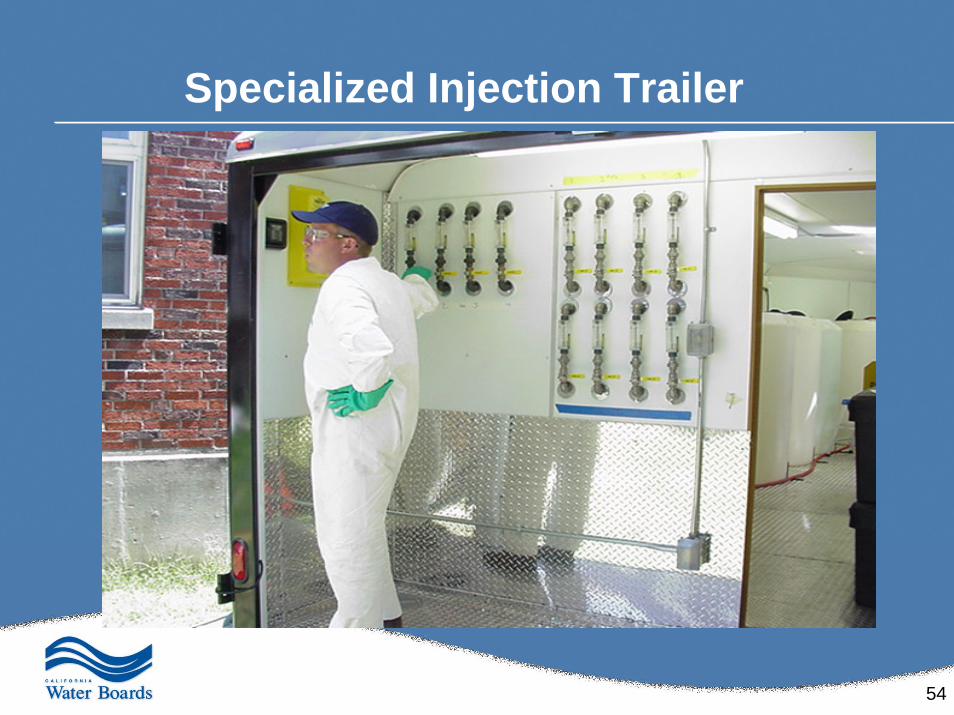
Specialized Injection Trailer
55
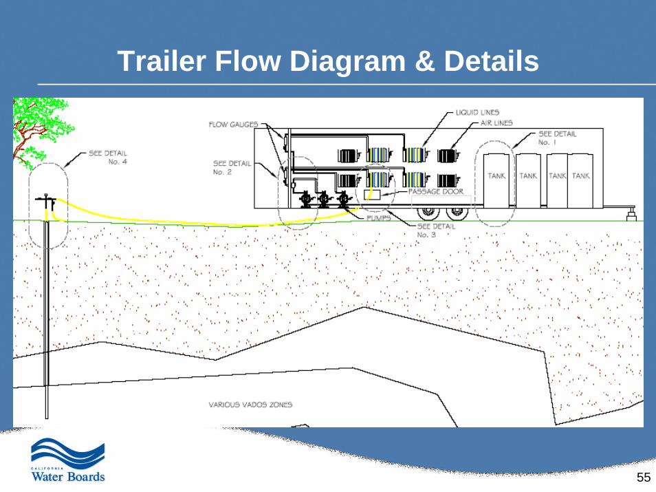
Trailer Flow Diagram & Details
56
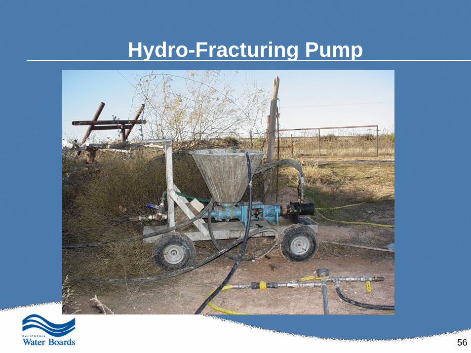
Hydro-Fracturing Pump
57
Evaluate Site-Specific Lithologyfor Injection Efficiency & Effectiveness
• Homogeneous well-sorted, medium- to coarse-grained sand is the best lithology– high permeability and low hydrostatic pressure
• Fractured bedrock can be injected into through temporary, drilled points– However, flow rate, volume and treatment effectiveness need to be
monitored closely to ensure that the micro-fractures within the bedrock don’t become clogged or congested
• Overlying clay layers increase the probability of success– Because they form a seal, or cap, that prevents treatment chemistry
from exuding through the surface and improves horizontal dispersion
• Most lithologies can be injected into…– However, the more heterogeneous the formation is and the more clayey
the site is, the harder it is to predict and direct exactly where the reagents are going
58
Design Criteria for Implementation
Pilot study should be conducted before full scale operations
• Pilot study will ensure that: – Results of the TOD and bench scale treatability study are
effective in their design – Design criteria are modified as needed before full-scale
implementation & operations
• Pilot study should be conducted within and adjacent to the most contaminated zone on site– Utilizing at least one monitoring well or compliance point
– Should be a representative location of the site
59
Design Criteria for Pilot Testing (cont.)
Pilot tests are performed on a representative portion of the field site to evaluate & determine critical design factors:
• Radius of influence, rate of application, and bulk mass transport effectiveness
• Maintenance of subsurface temperature and pressure in a safe andefficient manner
• Efficiency and effectiveness of the chemical reactions
• Field oxidant mass/volume delivery & dose estimates
• Sustained delivery rates can be achieved
• Cost estimates for full-scale implementation
60
Design Criteria for Full-Scale Implementation
• Full scale design is based on observations from the pilot test along with bench test and NOD results
• Final field oxidant mass/volume delivery & dose estimates
• Determination of final Cost estimates for full-scale implementation
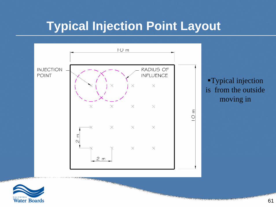
61
Typical Injection Point Layout
Typical injection is from the outside
moving in
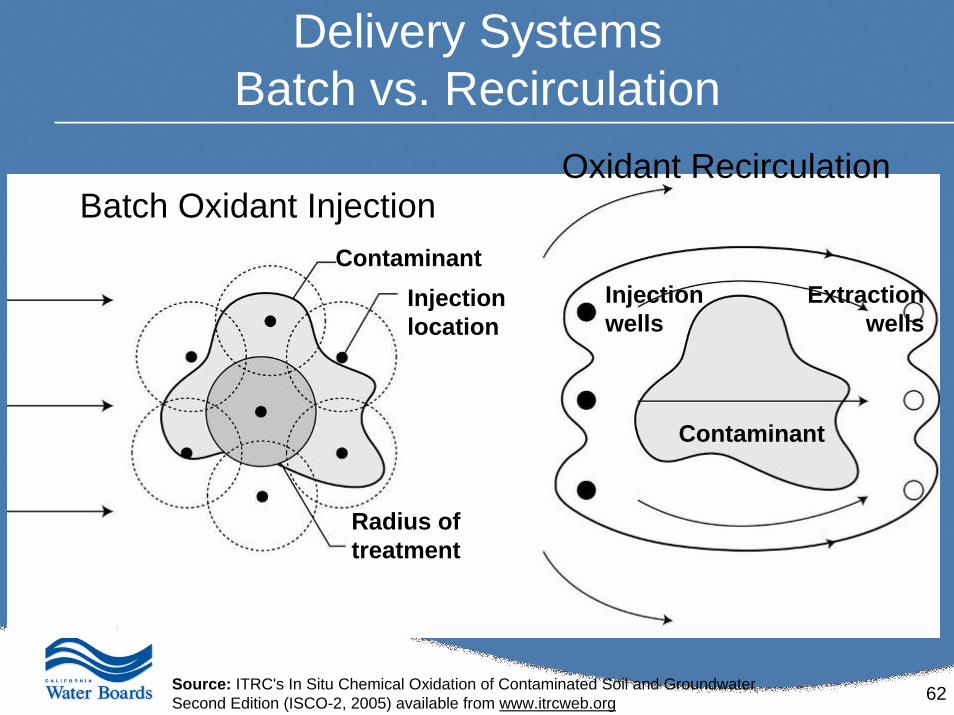
62
Delivery SystemsBatch vs. Recirculation
Batch Oxidant InjectionOxidant Recirculation
Injection wells
Extraction wells
Contaminant
ContaminantInjection location
Radius of treatment
Source: ITRC's In Situ Chemical Oxidation of Contaminated Soil and GroundwaterSecond Edition (ISCO-2, 2005) available from www.itrcweb.org
63
Conditions that Require Special Consideration
• Low permeable soils• Deep aquifers and very shallow aquifers• LNAPL / DNAPL• Confined formations• High organic soils• Old landfills and dumps• River embankments• Under buildings
Source: ITRC's In Situ Chemical Oxidation of Contaminated Soil and GroundwaterSecond Edition (ISCO-2, 2005) available from www.itrcweb.org
64
Delivery Systems Application
Approaches to increase effectiveness:
• Recirculation
• Pneumatic fracturing
• Hydraulic fracturing
• Unsaturated zone delivery
Source: ITRC's In Situ Chemical Oxidation of Contaminated Soil and GroundwaterSecond Edition (ISCO-2, 2005) available from www.itrcweb.org
65
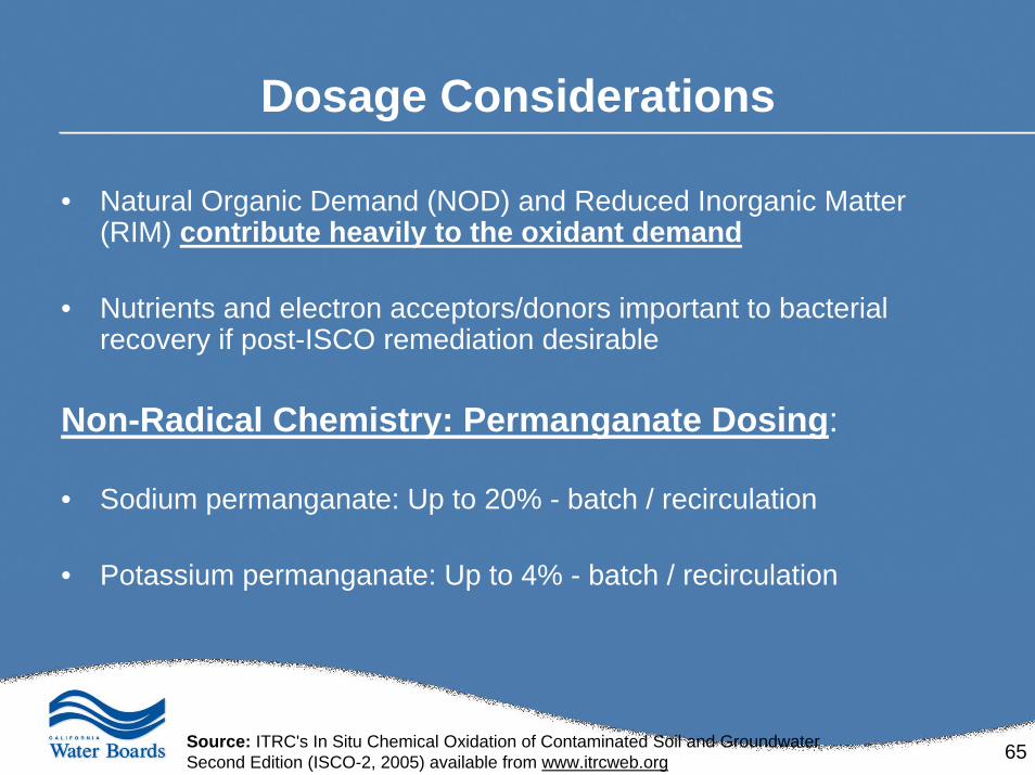
Dosage Considerations
• Natural Organic Demand (NOD) and Reduced Inorganic Matter (RIM) contribute heavily to the oxidant demand
• Nutrients and electron acceptors/donors important to bacterial recovery if post-ISCO remediation desirable
Non-Radical Chemistry: Permanganate Dosing:
• Sodium permanganate: Up to 20% - batch / recirculation
• Potassium permanganate: Up to 4% - batch / recirculation
Source: ITRC's In Situ Chemical Oxidation of Contaminated Soil and GroundwaterSecond Edition (ISCO-2, 2005) available from www.itrcweb.org
66
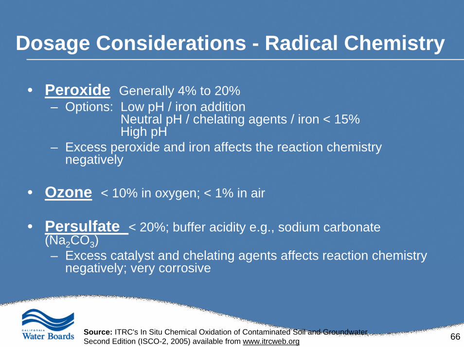
Dosage Considerations - Radical Chemistry
• Peroxide Generally 4% to 20%– Options: Low pH / iron addition
Neutral pH / chelating agents / iron < 15%High pH
– Excess peroxide and iron affects the reaction chemistry negatively
• Ozone < 10% in oxygen; < 1% in air
• Persulfate < 20%; buffer acidity e.g., sodium carbonate (Na2CO3)– Excess catalyst and chelating agents affects reaction chemistry
negatively; very corrosive
Source: ITRC's In Situ Chemical Oxidation of Contaminated Soil and GroundwaterSecond Edition (ISCO-2, 2005) available from www.itrcweb.org
67
Chemical Oxidant Loading
Is based on the four main points• Average contaminant loading in the groundwater• Average soil concentrations: this will take into account
sorbed-phase material• Natural organic demand (NOD)• Area of the plume Width*Length*Depth
68
Monitoring Chemox Remediation
69
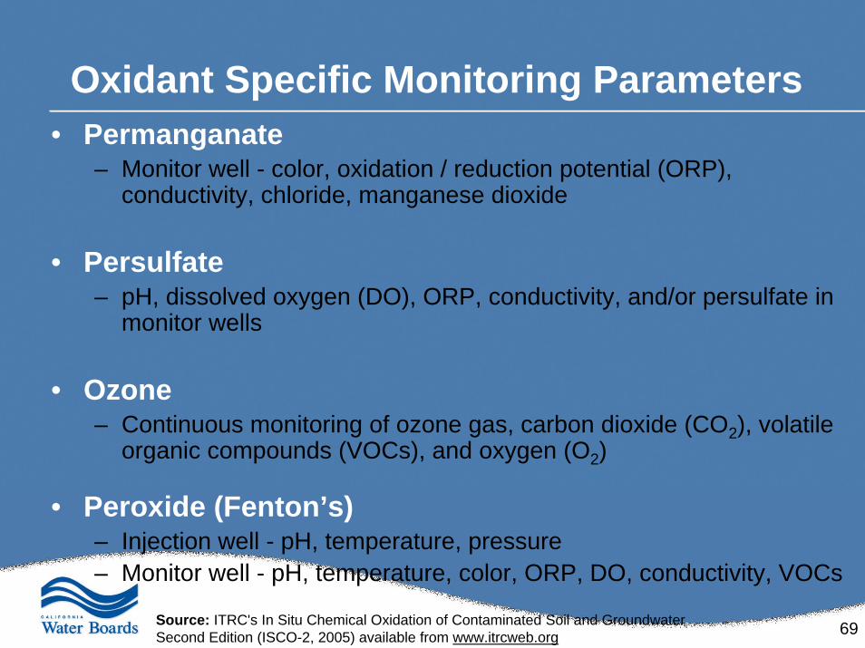
Oxidant Specific Monitoring Parameters• Permanganate
– Monitor well - color, oxidation / reduction potential (ORP), conductivity, chloride, manganese dioxide
• Persulfate– pH, dissolved oxygen (DO), ORP, conductivity, and/or persulfate in
monitor wells
• Ozone– Continuous monitoring of ozone gas, carbon dioxide (CO2), volatile
organic compounds (VOCs), and oxygen (O2)
• Peroxide (Fenton’s)– Injection well - pH, temperature, pressure– Monitor well - pH, temperature, color, ORP, DO, conductivity, VOCs
Source: ITRC's In Situ Chemical Oxidation of Contaminated Soil and GroundwaterSecond Edition (ISCO-2, 2005) available from www.itrcweb.org
70
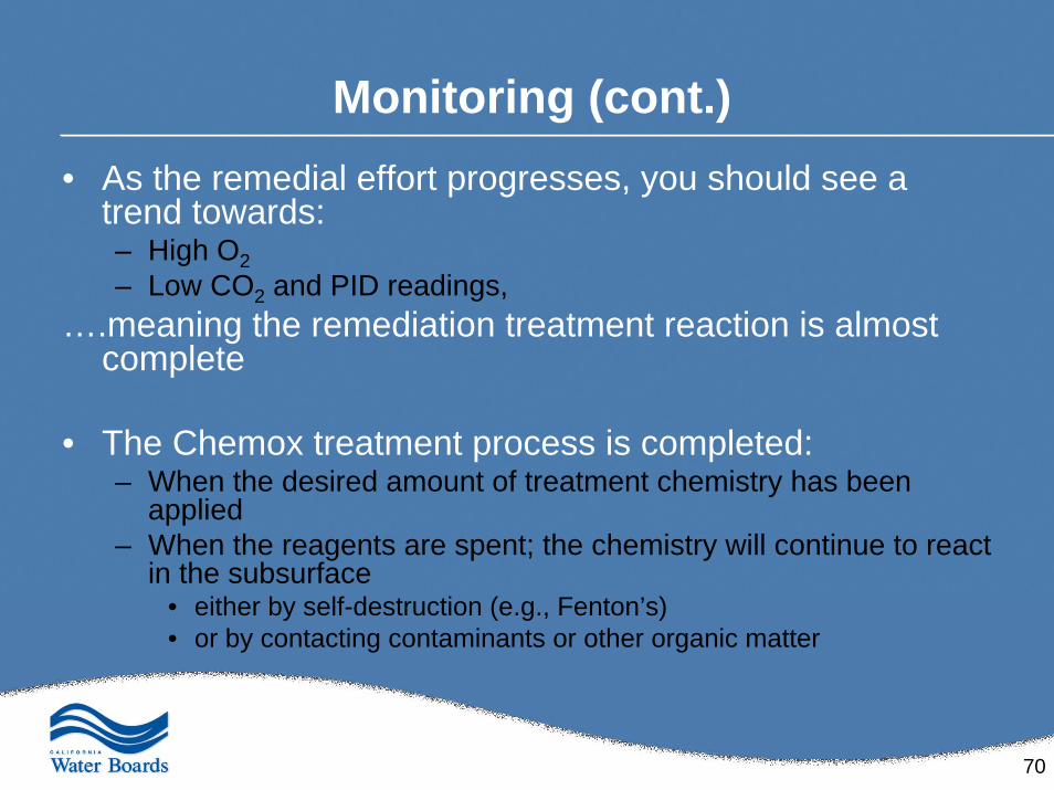
Monitoring (cont.)• As the remedial effort progresses, you should see a
trend towards: – High O2– Low CO2 and PID readings,
….meaning the remediation treatment reaction is almost complete
• The Chemox treatment process is completed:– When the desired amount of treatment chemistry has been
applied– When the reagents are spent; the chemistry will continue to react
in the subsurface • either by self-destruction (e.g., Fenton’s)• or by contacting contaminants or other organic matter
71
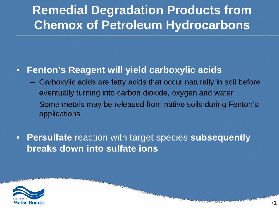
Remedial Degradation Products from Chemox of Petroleum Hydrocarbons
• Fenton’s Reagent will yield carboxylic acids– Carboxylic acids are fatty acids that occur naturally in soil before
eventually turning into carbon dioxide, oxygen and water– Some metals may be released from native soils during Fenton’s
applications
• Persulfate reaction with target species subsequently breaks down into sulfate ions
72
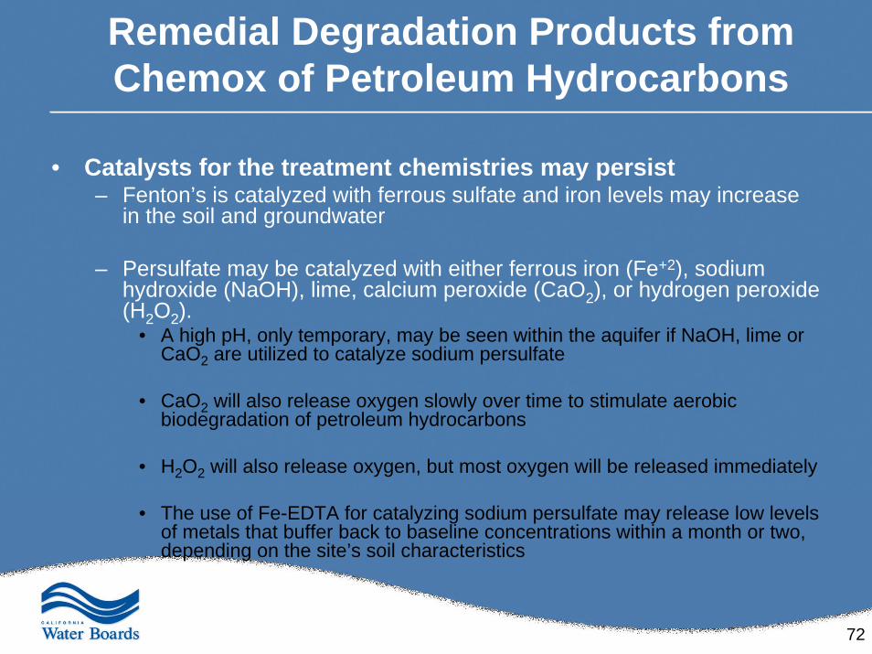
Remedial Degradation Products from Chemox of Petroleum Hydrocarbons
• Catalysts for the treatment chemistries may persist– Fenton’s is catalyzed with ferrous sulfate and iron levels may increase
in the soil and groundwater
– Persulfate may be catalyzed with either ferrous iron (Fe+2), sodium hydroxide (NaOH), lime, calcium peroxide (CaO2), or hydrogen peroxide (H2O2).
• A high pH, only temporary, may be seen within the aquifer if NaOH, lime or CaO2 are utilized to catalyze sodium persulfate
• CaO2 will also release oxygen slowly over time to stimulate aerobic biodegradation of petroleum hydrocarbons
• H2O2 will also release oxygen, but most oxygen will be released immediately
• The use of Fe-EDTA for catalyzing sodium persulfate may release low levels of metals that buffer back to baseline concentrations within a month or two, depending on the site’s soil characteristics
73
Vapor Observations• No observed lag-time - vertically or horizontally
• Field measurement of vapors closely correlated to the quantity of oxidant being injected
• Vapor generation appears mobile and widespread in the subsurface– Can be a HSE concern
• Indications that vapor can exist several hours after ceasing oxidant injection– Can be a HSE concern
With subsurface vapor/pressure generation (e.g., Fenton’s Reagent), Chemox should not to be implemented without full-focus and evaluation of HSE concerns
vapor migration pathways, receptors, etc.
74
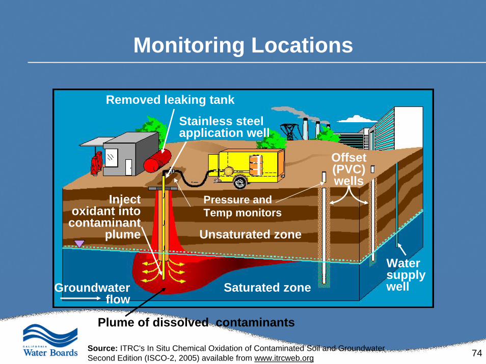
Monitoring Locations
Groundwater flow
Plume of dissolved contaminants
Inject oxidant into contaminant
plume
Removed leaking tank
Stainless steel application well
Unsaturated zone
Saturated zone
Water supply well
Offset (PVC) wells
Pressure and Temp monitors
Source: ITRC's In Situ Chemical Oxidation of Contaminated Soil and GroundwaterSecond Edition (ISCO-2, 2005) available from www.itrcweb.org
75
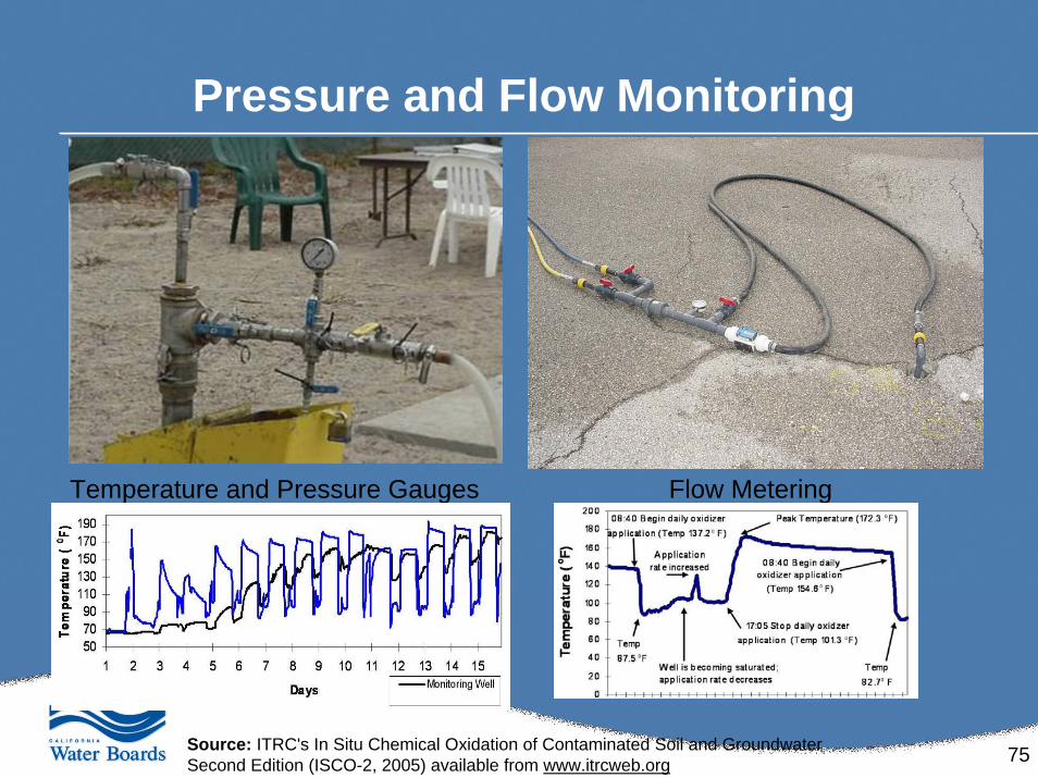
Pressure and Flow Monitoring
Temperature and Pressure Gauges Flow Metering
Source: ITRC's In Situ Chemical Oxidation of Contaminated Soil and GroundwaterSecond Edition (ISCO-2, 2005) available from www.itrcweb.org
76
Case Histories:Bench-, Pilot- and Full-Scale
77
Case Studies - Background• The case studies presented here represent both
petroleum hydrocarbons and chlorinated solvents.
• In general, clients tend to go directly to Pilot-scale Chemox applications for petroleum hydrocarbons without bench-scale.
• While this trend for Chemox of petroleum hydrocarbons exists, these following case studies offer reasons why scale-up testing can be valuable and should be considered as a useful, cost-effective step in scaling up the design of Chemox systems targeting petroleum.
78
Case Study #1
Property RedevelopmentPilot-Scale
79
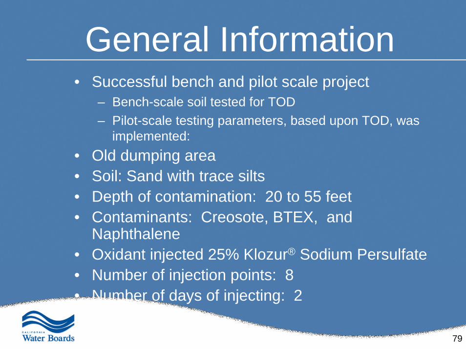
General Information• Successful bench and pilot scale project
– Bench-scale soil tested for TOD– Pilot-scale testing parameters, based upon TOD, was
implemented:• Old dumping area• Soil: Sand with trace silts• Depth of contamination: 20 to 55 feet• Contaminants: Creosote, BTEX, and
Naphthalene • Oxidant injected 25% Klozur® Sodium Persulfate• Number of injection points: 8• Number of days of injecting: 2
80
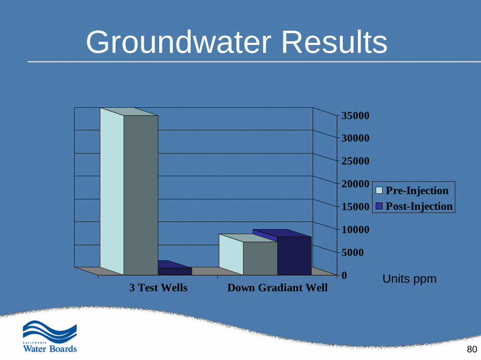
Groundwater Results
0
5000
10000
15000
20000
25000
30000
35000
3 Test Wells Down Gradiant Well
Pre-InjectionPost-Injection
Units ppm
81
Case Study # 2
Site Redevelopment
82
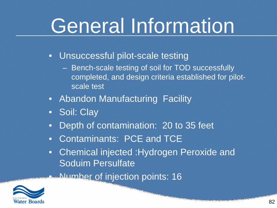
General Information• Unsuccessful pilot-scale testing
– Bench-scale testing of soil for TOD successfully completed, and design criteria established for pilot-scale test
• Abandon Manufacturing Facility• Soil: Clay• Depth of contamination: 20 to 35 feet• Contaminants: PCE and TCE• Chemical injected :Hydrogen Peroxide and
Soduim Persulfate• Number of injection points: 16
83
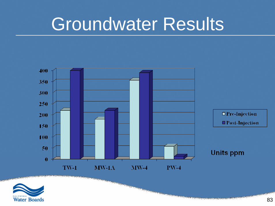
Groundwater Results
84
Case Study # 3
Property Transaction Site
85
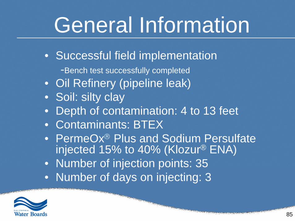
General Information• Successful field implementation
-Bench test successfully completed
• Oil Refinery (pipeline leak)• Soil: silty clay• Depth of contamination: 4 to 13 feet• Contaminants: BTEX• PermeOx® Plus and Sodium Persulfate
injected 15% to 40% (Klozur® ENA)• Number of injection points: 35• Number of days on injecting: 3
86
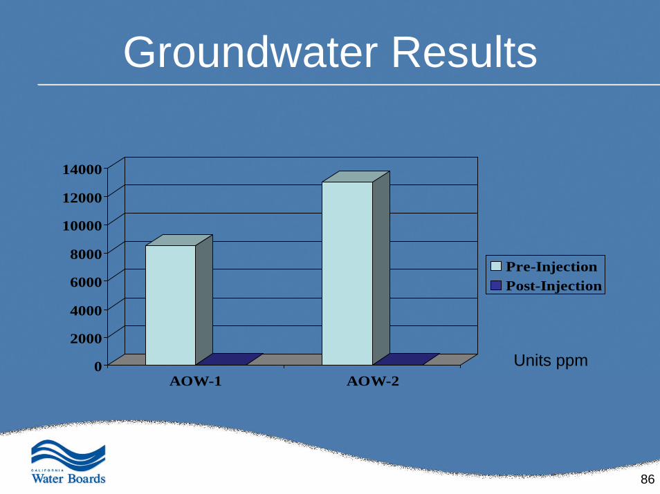
Groundwater Results
0
2000
4000
6000
8000
10000
12000
14000
AOW-1 AOW-2
Pre-InjectionPost-Injection
Units ppm
87
Case Study # 4• Successful bench-scale testing of soil containing
petroleum hydrocarbons and lead– Soil sample was tested for TOD– Successful treatment of lead noted, but natural oxidant demand
was high, resulting in the need for multiple oxidant injections to overcome the oxidant demand and to achieve satisfactory petroleum hydrocarbon reductions
• The site area proved to be too small for a pilot-scale test• Due to background oxidant demand needing to be
overcome in order to reduce CoC levels, Chemox at this site was not a costs-effective option– Dig & haul was a more cost-effective option offering assurance
that all CoC contamination was removed from the site
88
Case Study # 5
Property Transaction Site
In-Situ Enhanced Vacuum Truck Recovery
89
In-Situ Solubilization & Recovery• One of the techniques used to overcome the problem of the slow release of immobilized NAPLs is to solubilizethem with surfactants (Edwards, D. A. et al).
• Surfactants are capable of emulsifying NAPLs to facilitate increased mobility and recovery efficiency (Chevalier et al., 1997; Abdul et al., 1990)
• In many cases this technique can then enhance bioremediation if the surfactant is not toxic to the NAPL degrading microorganisms
90
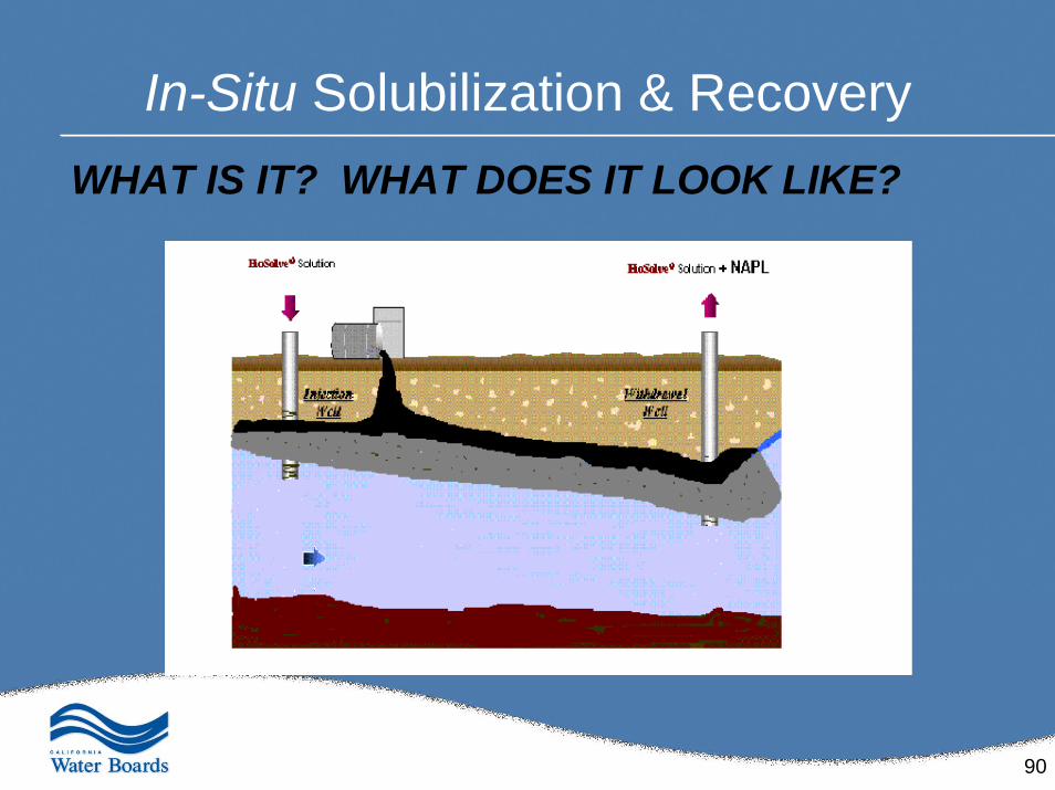
In-Situ Solubilization & RecoveryWHAT IS IT? WHAT DOES IT LOOK LIKE?
91
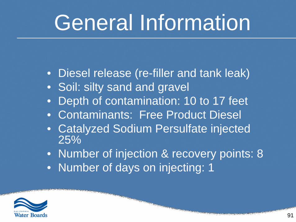
General Information
• Diesel release (re-filler and tank leak)• Soil: silty sand and gravel• Depth of contamination: 10 to 17 feet• Contaminants: Free Product Diesel • Catalyzed Sodium Persulfate injected
25% • Number of injection & recovery points: 8• Number of days on injecting: 1
92
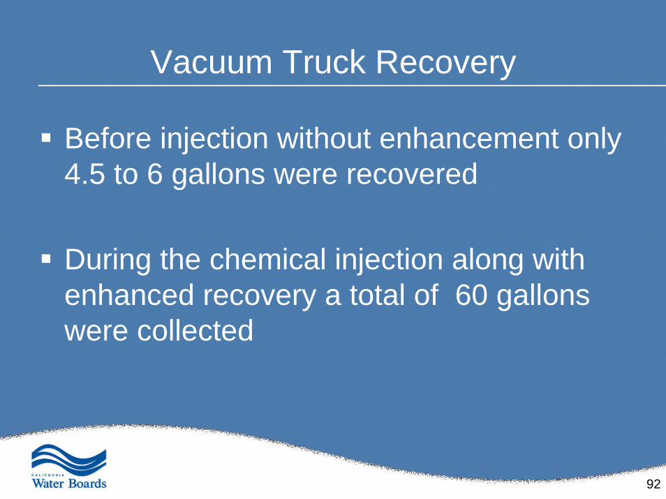
Vacuum Truck Recovery
Before injection without enhancement only 4.5 to 6 gallons were recovered
During the chemical injection along with enhanced recovery a total of 60 gallons were collected
93
Variable Project Costs
Volume of contaminant Size of the plumeType of lithologyDays on site
94
Keys to Success
• Delineation• Right chemistry• Proper implementation
95
Question and Answers Relating to Chemical Treatment
96
Regulatory Concerns & Issues
Performance monitoringPerformance expectations
Total mass evaluationRegulatory perspective
97
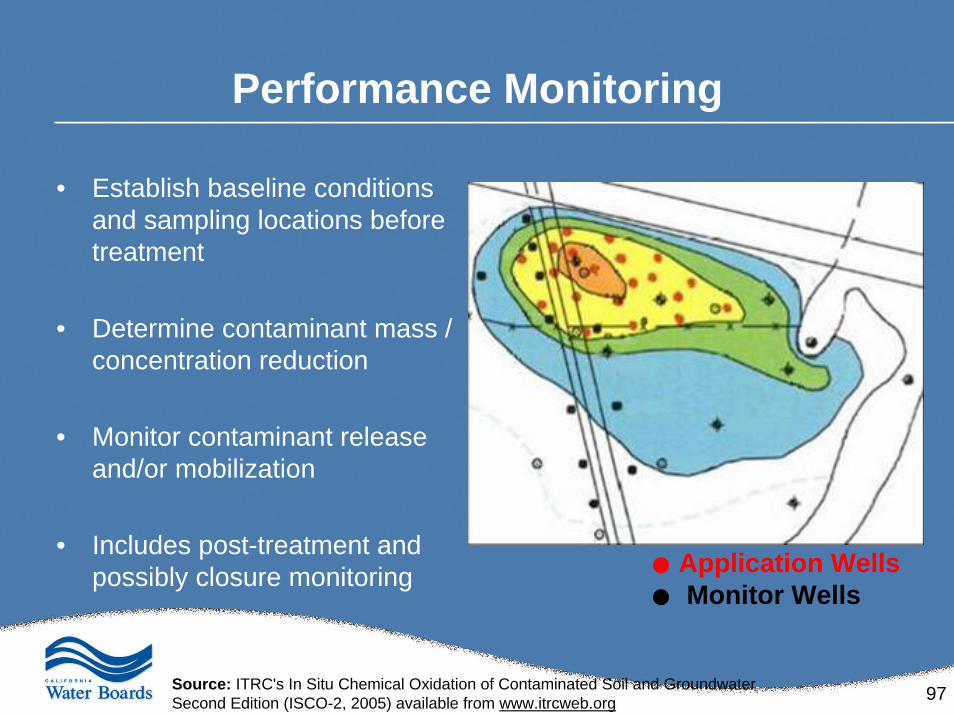
Performance Monitoring
• Establish baseline conditions and sampling locations before treatment
• Determine contaminant mass / concentration reduction
• Monitor contaminant release and/or mobilization
• Includes post-treatment and possibly closure monitoring Application Wells
Monitor Wells
Source: ITRC's In Situ Chemical Oxidation of Contaminated Soil and GroundwaterSecond Edition (ISCO-2, 2005) available from www.itrcweb.org
98
Performance Expectations
Risk, Mass, and Toxicity Reductions• ISCO reduces contaminant mass through the
oxidation process
• Mass reduction = reduction in risk
• Rapid reduction of source area concentrations to acceptable levels for biological polishing and plume control
Source: ITRC's In Situ Chemical Oxidation of Contaminated Soil and GroundwaterSecond Edition (ISCO-2, 2005) available from www.itrcweb.org
99
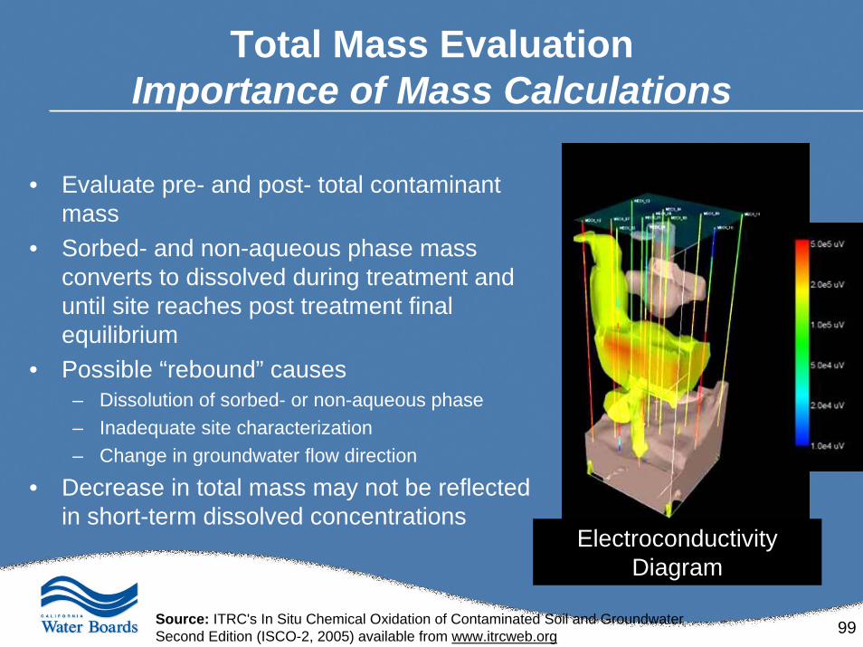
Total Mass EvaluationImportance of Mass Calculations
• Evaluate pre- and post- total contaminant mass
• Sorbed- and non-aqueous phase mass converts to dissolved during treatment and until site reaches post treatment final equilibrium
• Possible “rebound” causes– Dissolution of sorbed- or non-aqueous phase– Inadequate site characterization– Change in groundwater flow direction
• Decrease in total mass may not be reflected in short-term dissolved concentrations
ElectroconductivityDiagram
Source: ITRC's In Situ Chemical Oxidation of Contaminated Soil and GroundwaterSecond Edition (ISCO-2, 2005) available from www.itrcweb.org
100
Regulatory Perspective Summary
Life of a regulator• Too many cases/many deadlines• Needs to make sound technical decisions in a timely
manner
The ISCO-2 document and other technical references…• Detailed background information included• Allows a regulator to feel much more confident in
reviewing an ISCO proposal• Provides a list of contacts
Source: ITRC's In Situ Chemical Oxidation of Contaminated Soil and GroundwaterSecond Edition (ISCO-2, 2005) available from www.itrcweb.org

101
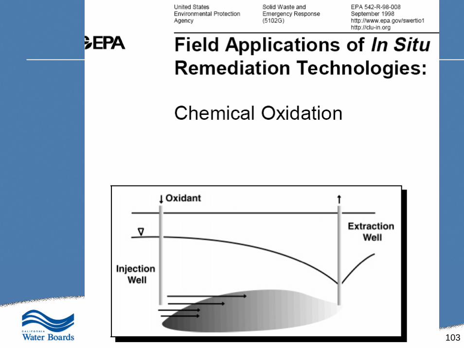
Additional References
102
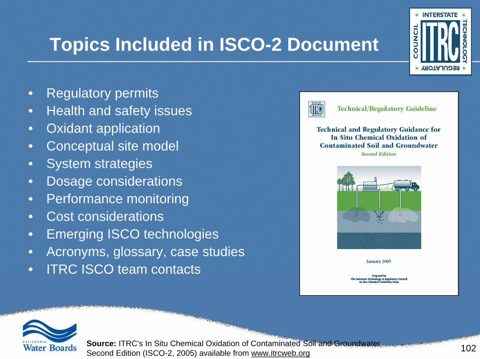
Topics Included in ISCO-2 Document
• Regulatory permits• Health and safety issues• Oxidant application• Conceptual site model• System strategies• Dosage considerations• Performance monitoring• Cost considerations• Emerging ISCO technologies• Acronyms, glossary, case studies• ITRC ISCO team contacts
Source: ITRC's In Situ Chemical Oxidation of Contaminated Soil and GroundwaterSecond Edition (ISCO-2, 2005) available from www.itrcweb.org
103
104
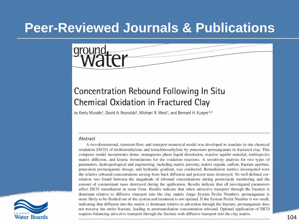
Peer-Reviewed Journals & Publications
105
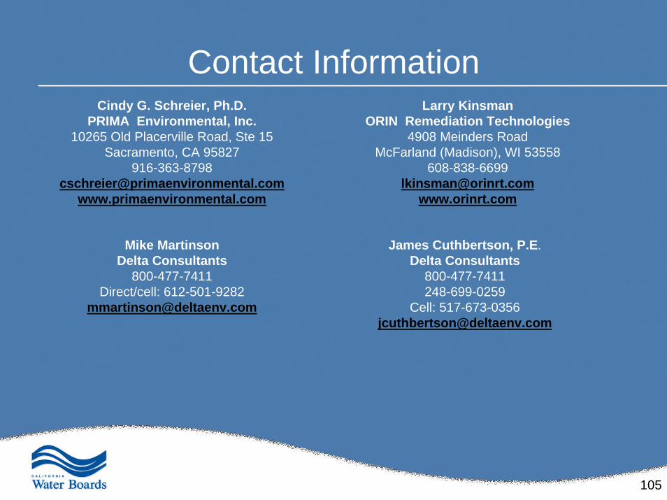
Contact Information
Mike MartinsonDelta Consultants
800-477-7411Direct/cell: 612-501-9282
Cindy G. Schreier, Ph.D.PRIMA Environmental, Inc.
10265 Old Placerville Road, Ste 15Sacramento, CA 95827
www.primaenvironmental.com
James Cuthbertson, P.E.Delta Consultants
800-477-7411248-699-0259
Cell: [email protected]
Larry KinsmanORIN Remediation Technologies
4908 Meinders RoadMcFarland (Madison), WI 53558
608-838-6699 [email protected]
www.orinrt.com