Embed Size (px)
Citation preview

Level set based topology optimization for optical cloaksGaruda Fujii, Hayato Watanabe, Takayuki Yamada, Tsuyoshi Ueta, and Mamoru Mizuno Citation: Applied Physics Letters 102, 251106 (2013); doi: 10.1063/1.4812471 View online: http://dx.doi.org/10.1063/1.4812471 View Table of Contents: http://scitation.aip.org/content/aip/journal/apl/102/25?ver=pdfcov Published by the AIP Publishing Articles you may be interested in Design of a two-dimensional metamaterial cloak with minimum scattering using a quadratic transformationfunction J. Appl. Phys. 116, 124501 (2014); 10.1063/1.4893480 Superscattering of light optimized by a genetic algorithm Appl. Phys. Lett. 105, 011109 (2014); 10.1063/1.4887475 Localized transformation optics devices Appl. Phys. Lett. 103, 214104 (2013); 10.1063/1.4833279 Spherical cloaking using multilayer shells of ordinary dielectrics AIP Advances 3, 112111 (2013); 10.1063/1.4831942 Topology optimized low-contrast all-dielectric optical cloak Appl. Phys. Lett. 98, 021112 (2011); 10.1063/1.3540687
This article is copyrighted as indicated in the article. Reuse of AIP content is subject to the terms at: http://scitation.aip.org/termsconditions. Downloaded to IP: 129.174.21.5
On: Sun, 21 Dec 2014 22:48:38
Level set based topology optimization for optical cloaks
Garuda Fujii,1,a) Hayato Watanabe,2 Takayuki Yamada,3 Tsuyoshi Ueta,4
and Mamoru Mizuno1
1Faculty of Systems Science and Technology, Akita Prefectural University, Yurihonjo 015-0055, Japan2Department of Mechanical Science and Engineering, Nagoya University, Nagoya 464-8603, Japan3Department of Mechanical Engineering and Science, Kyoto University, Kyoto 615-8540, Japan4Physics Laboratory, The Jikei University School of Medicine, Tokyo 182-8570, Japan
(Received 17 December 2012; accepted 9 June 2013; published online 25 June 2013)
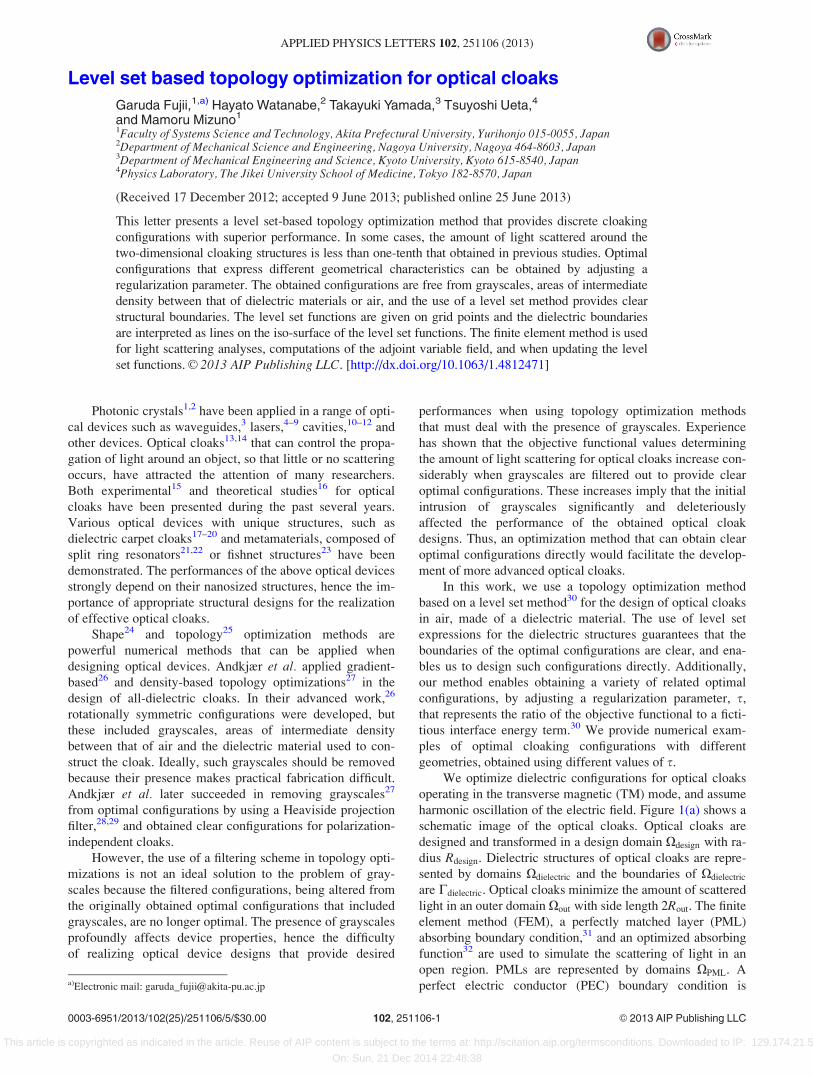
This letter presents a level set-based topology optimization method that provides discrete cloaking
configurations with superior performance. In some cases, the amount of light scattered around the
two-dimensional cloaking structures is less than one-tenth that obtained in previous studies. Optimal
configurations that express different geometrical characteristics can be obtained by adjusting a
regularization parameter. The obtained configurations are free from grayscales, areas of intermediate
density between that of dielectric materials or air, and the use of a level set method provides clear
structural boundaries. The level set functions are given on grid points and the dielectric boundaries
are interpreted as lines on the iso-surface of the level set functions. The finite element method is used
for light scattering analyses, computations of the adjoint variable field, and when updating the level
set functions. VC 2013 AIP Publishing LLC. [http://dx.doi.org/10.1063/1.4812471]
Photonic crystals1,2 have been applied in a range of opti-
cal devices such as waveguides,3 lasers,4–9 cavities,10–12 and
other devices. Optical cloaks13,14 that can control the propa-
gation of light around an object, so that little or no scattering
occurs, have attracted the attention of many researchers.
Both experimental15 and theoretical studies16 for optical
cloaks have been presented during the past several years.
Various optical devices with unique structures, such as
dielectric carpet cloaks17–20 and metamaterials, composed of
split ring resonators21,22 or fishnet structures23 have been
demonstrated. The performances of the above optical devices
strongly depend on their nanosized structures, hence the im-
portance of appropriate structural designs for the realization
of effective optical cloaks.
Shape24 and topology25 optimization methods are
powerful numerical methods that can be applied when
designing optical devices. Andkjær et al. applied gradient-
based26 and density-based topology optimizations27 in the
design of all-dielectric cloaks. In their advanced work,26
rotationally symmetric configurations were developed, but
these included grayscales, areas of intermediate density
between that of air and the dielectric material used to con-
struct the cloak. Ideally, such grayscales should be removed
because their presence makes practical fabrication difficult.
Andkjær et al. later succeeded in removing grayscales27
from optimal configurations by using a Heaviside projection
filter,28,29 and obtained clear configurations for polarization-
independent cloaks.
However, the use of a filtering scheme in topology opti-
mizations is not an ideal solution to the problem of gray-
scales because the filtered configurations, being altered from
the originally obtained optimal configurations that included
grayscales, are no longer optimal. The presence of grayscales
profoundly affects device properties, hence the difficulty
of realizing optical device designs that provide desired
performances when using topology optimization methods
that must deal with the presence of grayscales. Experience
has shown that the objective functional values determining
the amount of light scattering for optical cloaks increase con-
siderably when grayscales are filtered out to provide clear
optimal configurations. These increases imply that the initial
intrusion of grayscales significantly and deleteriously
affected the performance of the obtained optical cloak
designs. Thus, an optimization method that can obtain clear
optimal configurations directly would facilitate the develop-
ment of more advanced optical cloaks.
In this work, we use a topology optimization method
based on a level set method30 for the design of optical cloaks
in air, made of a dielectric material. The use of level set
expressions for the dielectric structures guarantees that the
boundaries of the optimal configurations are clear, and ena-
bles us to design such configurations directly. Additionally,
our method enables obtaining a variety of related optimal
configurations, by adjusting a regularization parameter, s,
that represents the ratio of the objective functional to a ficti-
tious interface energy term.30 We provide numerical exam-
ples of optimal cloaking configurations with different
geometries, obtained using different values of s.
We optimize dielectric configurations for optical cloaks
operating in the transverse magnetic (TM) mode, and assume
harmonic oscillation of the electric field. Figure 1(a) shows a
schematic image of the optical cloaks. Optical cloaks are
designed and transformed in a design domain Xdesign with ra-
dius Rdesign. Dielectric structures of optical cloaks are repre-
sented by domains Xdielectric and the boundaries of Xdielectric
are Cdielectric. Optical cloaks minimize the amount of scattered
light in an outer domain Xout with side length 2Rout. The finite
element method (FEM), a perfectly matched layer (PML)
absorbing boundary condition,31 and an optimized absorbing
function32 are used to simulate the scattering of light in an
open region. PMLs are represented by domains XPML. A
perfect electric conductor (PEC) boundary condition isa)Electronic mail: [email protected]
0003-6951/2013/102(25)/251106/5/$30.00 VC 2013 AIP Publishing LLC102, 251106-1
APPLIED PHYSICS LETTERS 102, 251106 (2013)
This article is copyrighted as indicated in the article. Reuse of AIP content is subject to the terms at: http://scitation.aip.org/termsconditions. Downloaded to IP: 129.174.21.5
On: Sun, 21 Dec 2014 22:48:38
implemented on CPEC, the boundary of a circular PEC with
radius RPEC, to model a strongly scattering object placed at
the center of the Xdesign domain. The total electric field Ez can
be expressed as the sum of respective scattering and incident
fields, Es and Ei
Ez ¼ Es þ Ei :
The incident field Ei is assumed to be plane waves propagat-
ing in the positive x direction. The wavelength of the inci-
dent plane waves in free space is fixed at Rdesign=2:5. We
solve a simple Helmholtz equation as follows:
r2Es þx2
c2�ðxÞEs ¼ �
x2
c2½�ðxÞ � �background�Ei ;
where c is the velocity of light in a vacuum and �background is
the relative permittivity of the background, which is assumed
to be 1. The position-dependent relative permittivity �ðxÞ is
defined in both Xdesign and Xout as follows:
�ðxÞ ¼ �background þ vð�dielectric � �backgroundÞ x 2 Xdesign
�background x 2 Xout;
�
where �dielectric is the relative permittivity of the dielectric
material and v is a characteristic function defined in
Xdesign as
vð/ðxÞÞ ¼ 1 if x 2 Xdielectric;0 if x 2 Xdesign =Xdielectric;
�
where /ðxÞ are level set functions defined as piecewise
constant values to the dielectric material boundaries, such
that
�1 � /ðxÞ < 0 for 8x 2 Xdesign =Xdielectric;/ðxÞ ¼ 0 for 8x 2 Cdielectric;0 < /ðxÞ � 1 for 8x 2 Xdielectric =Cdielectric:
8<:
The values of the level set functions are given with respect
to grid points as shown in Fig. 1(b). The functions are line-
arly interpolated at each location and have a value of 0 on
the dielectric boundaries. Finite elements are created based
on the boundaries. The interval between neighboring grid
points, Lgrid, is equal to Rdesign=100. The numbers of nodes
and elements in the FEM models are approximately 350 000
and 700 000, respectively.
In order to realize optical cloaks, Ez needs to be equal to
Ei; that is, Es ¼ 0. The objective functional for minimizing
light scattering around the dielectric structures is, therefore,
defined as
F ¼ 1
F0
ðXout
EsE�s dX; (1)
where E�s is the complex conjugate of Es and F0 is the inte-
grated intensity of the scattering field in Xout when no cloak
exists.
Topology optimizations need regularization to obtain
optimal configurations because such optimizations are ill-
posed problems. Based on the formulation of the level
set-based topology optimization method,30 the objective func-
tional (1) is regularized here by adding a fictitious interface
energy term derived from the phase field model as follows:
Fregularized ¼1
F0
ðXout
EsE�s dXþ
ðXdesign
1
2sjr/j2dX;
where s is a positive regularization parameter that represents
the ratio of the objective functional to the fictitious interface
energy term. The above regularization, with its fictitious
energy term, also acts a perimeter control, a type of geomet-
rical constraint. The geometrical constraint becomes weaker,
and optimal configurations can become more complex. As sis set to larger values, the fictitious interface energy is
increased, the perimeter becomes shorter, the geometrical
constraint becomes stronger, and optimal configurations
become more simple. Therefore, by adjusting the value of s,
optimal configurations that express different geometries can
be obtained. The length of the perimeter of the dielectric
structure, Lp, thus inversely indicates the degree to which the
geometrical constraint is active. The operation of this perim-
eter control enables us to obtain several different optical
cloak configurations, each of which is optimal. Thus, the
obtained optimal solutions are not unique, but give the local
minimum of the functional in the configuration space for
each value of s. Parameter s is never set to 0 because this
would negate the regularization, so the topology optimiza-
tion would revert to being an ill-posed problem.
Figures 2 and 3, respectively, show optimal configura-
tions and normalized total electric fields for a variety of
cases using different values of the regularization parameter
s. The objective functional values F for corresponding values
of s are shown in Fig. 3 subparts. As s is made smaller, the
normalized perimeter value Lp=Rdesign, representing the
degree of geometrical constraint, increases as shown in
Fig. 2, and the value of F decreases as shown in Fig. 4. In
particular, when s � 1:2� 10�5, the value of F is less than
one-tenth of that presented in a previous study [Fig. 3(d) in
Ref. 27: Cloak designs and associated objective values U for
Ez polarization]. The performances of the above cloaking
configurations are considerably improved in comparison
with those of the prior configuration. The sizes of the struc-
tural differences between optimal configurations illustrated
in Fig. 2 are obviously smaller than the wavelength of light,
but such small structures play an important role in preventing
light scattering around the cloak structures.
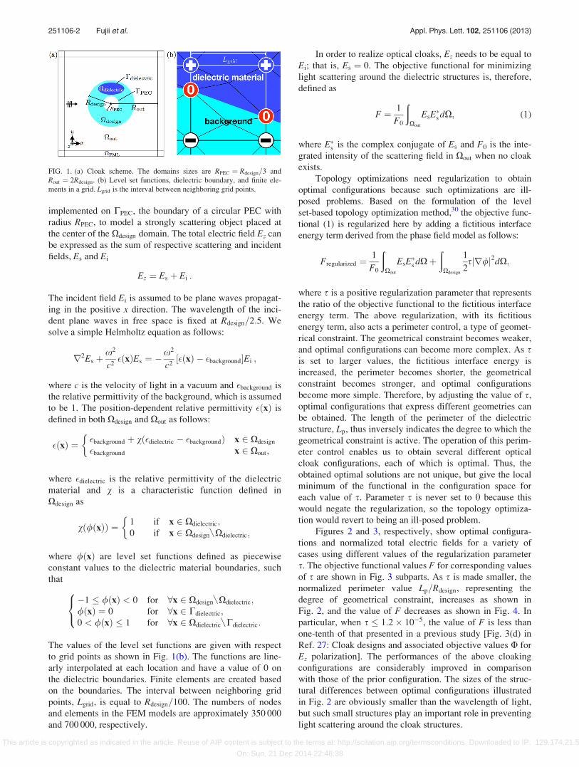
FIG. 1. (a) Cloak scheme. The domains sizes are RPEC ¼ Rdesign=3 and
Rout ¼ 2Rdesign. (b) Level set functions, dielectric boundary, and finite ele-
ments in a grid. Lgrid is the interval between neighboring grid points.
251106-2 Fujii et al. Appl. Phys. Lett. 102, 251106 (2013)
This article is copyrighted as indicated in the article. Reuse of AIP content is subject to the terms at: http://scitation.aip.org/termsconditions. Downloaded to IP: 129.174.21.5
On: Sun, 21 Dec 2014 22:48:38
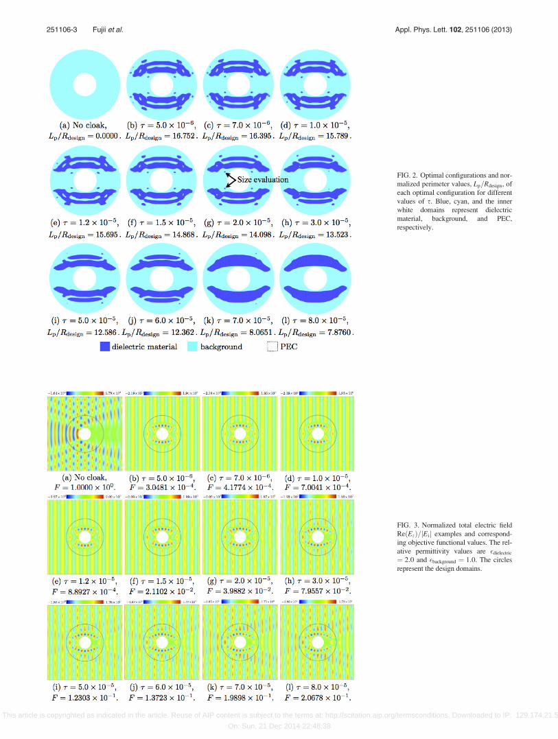
FIG. 2. Optimal configurations and nor-
malized perimeter values, Lp=Rdesign, of
each optimal configuration for different
values of s. Blue, cyan, and the inner
white domains represent dielectric
material, background, and PEC,
respectively.
FIG. 3. Normalized total electric field
ReðEzÞ=jEij examples and correspond-
ing objective functional values. The rel-
ative permittivity values are �dielectric
¼ 2:0 and �background ¼ 1:0. The circles
represent the design domains.
251106-3 Fujii et al. Appl. Phys. Lett. 102, 251106 (2013)
This article is copyrighted as indicated in the article. Reuse of AIP content is subject to the terms at: http://scitation.aip.org/termsconditions. Downloaded to IP: 129.174.21.5
On: Sun, 21 Dec 2014 22:48:38
We consider that ease or difficulty of fabricating an opti-
mal structure mainly depends on the size of the smallest
structural feature, and roughly estimate the accuracy required
to fabricate the obtained optimal configurations. Comparing
the optimal configuration when s ¼ 2:0� 10�5 with that
when s ¼ 3:0� 10�5 in Fig. 2, we find two small circular
structures, indicated with arrows in Fig. 2(g), which are not
present in Fig. 2(h). We regard the presence and lack of these
two circular structures as the most important difference
between these two optimal configurations, and evaluate the
size of these features. The difference between the normalized
perimeters, Lp=Rdesign, for these two configurations is 0.575.
Assuming that the wavelength of incident light is 400 nm,
the difference between the perimeters becomes DLp ¼ 575
nm. The radii of the two circular structures Rsd are then esti-
mated as Rsd ¼ 45:7 nm, which is equivalent to the maxi-
mum fabrication tolerance required to realize the obtained
optimal configuration. However, such small structures are
not present in the optimal configuration obtained when
s ¼ 8:0� 10�5, shown in Fig. 2(l). By exercising perimeter
control, we can obtain desirable configurations that not only
provide superior performance and are optimal but also have
appropriate geometries that can be fabricated using practical
and expedient techniques.
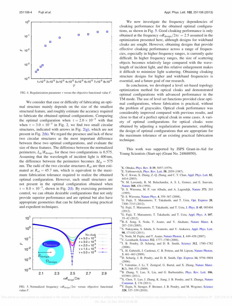
We now investigate the frequency dependencies of
cloaking performance for the obtained optimal configura-
tions, as shown in Fig. 5. Good cloaking performance is only
obtained at the frequency xRdesign=2pc ¼ 2:5 assumed in the
optimization presented here, although designs for wideband
cloaks are sought. However, obtaining designs that provide
effective cloaking performance across a range of frequen-
cies, especially in higher frequency ranges, is currently quite
difficult. In higher frequency ranges, the size of scattering
objects becomes relatively large compared with the wave-
length of incident light, and this relative enlargement makes
it difficult to minimize light scattering. Obtaining cloaking
structure designs for higher and wideband frequencies is
essential, and a future goal of our research.
In conclusion, we developed a level set-based topology
optimization method for optical cloaks and demonstrated
optimal configurations with advanced performance in the
TM mode. The use of level set functions provided clear opti-
mal configurations, whose fabrication is practical, without
the problem of grayscales. Optical cloak performance was
considerably improved compared with previous results, and
close to that of a perfect optical cloak in some cases. A vari-
ety of optimal configurations for optical cloaks were
obtained by adjusting a regularization parameter, enabling
the design of optimal configurations that are appropriate for
the maximum tolerance of an existing practical fabrication
technique.
This work was supported by JSPS Grant-in-Aid for
Young Scientists (Start-up) (Grant No. 24860050).
1K. Ohtaka, Phys. Rev. B 19, 5057 (1979).2E. Yablonovitch, Phys. Rev. Lett. 58, 2059 (1987).3K.-C. Kwan, X. Zhang, Z.-Q. Zhang, and C. T. Chan, Appl. Phys. Lett. 82,
4414 (2003).4N. M. Lawandy, R. M. Balachandra, A. S. L. Gomez, and E. Sauvain,
Nature 368, 436 (1994).5D. S. Wiersma, M. P. van Albada, and A. Lagendijk, Nature 373, 203
(1995).6D. S. Wiersma, Nature Phys. 4, 359–367 (2008).7G. Fujii, T. Matsumoto, T. Takahashi, and T. Ueta, Opt. Express 20,
7300–7315 (2012).8G. Fujii, T. Matsumoto, T. Takahashi, and T. Ueta, J. Phys. B 45, 085404
(2012).9G. Fujii, T. Matsumoto, T. Takahashi, and T. Ueta, Appl. Phys. A 107,
35–42 (2012).10B.-S. Song, S. Noda, T. Asano, and Y. Akahane, Nature Mater. 4,
207–210 (2005).11S. Nakayama, S. Ishida, S. Iwamoto, and Y. Arakawa, Appl. Phys. Lett.
98, 171102 (2011).12S. Noda, M. Fujita, and T. Asano, Nature Photon. 1, 449–458 (2007).13U. Leonhardt, Science 312, 1777–1780 (2006).14J. B. Pendry, D. Schurig, and D. R. Smith, Science 312, 1780–1782
(2006).15L. H. Gabrielli, J. Cardenas, C. B. Poitras, and M. Lipson, Nature Photon.
3, 461–463 (2009).16D. Schurig, J. B. Pendry, and D. R. Smith, Opt. Express 14, 9794–9804
(2006).17J. Valentine, J. Li, T. Zentgraf, G. Bartal, and X. Zhang, Nature Mater.
8(2), 568–571 (2009).18B. Zhang, Y. Luo, X. Liu, and G. Barbastathis, Phys. Rev. Lett. 106,
033901 (2011).19X. Chen, Y. Luo, J. Zhang, K. Jiang, J. B. Pendry, and S. Zhanga, Nature
Commun. 2, 176 (2011).20T. Ergin, N. Stenger, P. Brenner, J. B. Pendry, and M. Wegener, Science
328, 337–339 (2010).
FIG. 4. Regularization parameter s versus the objective functional value F.
FIG. 5. Normalized frequency xRdesign=2pc versus objective functional
value F.
251106-4 Fujii et al. Appl. Phys. Lett. 102, 251106 (2013)
This article is copyrighted as indicated in the article. Reuse of AIP content is subject to the terms at: http://scitation.aip.org/termsconditions. Downloaded to IP: 129.174.21.5
On: Sun, 21 Dec 2014 22:48:38

21D. R. Smith, W. J. Padilla, D. C. Vier, S. C. Nemat-Nasser, and S. Shultz,
Phys. Rev. Lett. 84, 4184–4187 (2000).22D. Schurig, J. J. Mock, B. J. Justine, S. A. Cummer, J. B. Pendry, A. F.
Starr, and D. R. Smith, Science 314, 977–980 (2006).23J. Valentine, S. Zhang, T. Zentgraf, E. Ulin-Avila, D. A. Genov, G. Bartal,
and X. Zhang, Nature 455, 376–380 (2008).24G. Allaire, F. Jouve, and A. M. Toader, J. Comput. Phys. 194, 363–393
(2004).25M. P. Bendsøe and N. Kikuchi, Comput. Methods Appl. Mech. Eng. 71(2),
197–224 (1988).26J. Andkjær and O. Sigmund, Appl. Phys. Lett. 98, 021112 (2011).
27J. Andkjær, N. A. Mortensen, and O. Sigmund, Appl. Phys. Lett. 100,
101106 (2012).28J. K. Guest, J. H. Pr�evost, and T. Belytschko, Int. J. Numer. Methods Eng.
61, 238–254 (2004).29F. Wang, B. S. Lazarov, and O. Sigmund, Struct. Multidiscip. Optim. 43,
767–784 (2011).30T. Yamada, K. Izui, S. Nishiwaki, and A. Takezawa, Comput. Methods
Appl. Mech. Eng. 199, 2876–2891 (2010).31J. P. Berenger, J. Comput. Phys. 114, 185 (1994).32A. Berm�udez, L. Hervella-Nieto, A. Prieto, and R. Rodr�ıguez, J. Comput.
Phys. 223, 469 (2007).
251106-5 Fujii et al. Appl. Phys. Lett. 102, 251106 (2013)
This article is copyrighted as indicated in the article. Reuse of AIP content is subject to the terms at: http://scitation.aip.org/termsconditions. Downloaded to IP: 129.174.21.5
On: Sun, 21 Dec 2014 22:48:38