Embed Size (px)
Citation preview

http://repository.osakafu-u.ac.jp/dspace/
TitleLevel Set-based Topology Optimization for the Design of Light-Trappin
g Structures
Author(s)Otomori, Masaki; Yamada, Takayuki; Izui, Kazuhiro; Nishiwaki, Shinji;
Kogiso, Nozomu
Editor(s)
Citation IEEE Transactions on Magnetics. 2014, 50 (2), p.394-396
Issue Date 2014-02-26
URL http://hdl.handle.net/10466/15649
Rights
(c) 2014 IEEE. Personal use of this material is permitted. Permission fro
m IEEE must be obtained for all other users, including reprinting/republi
shing this material for advertising or promotional purposes, creating new
collective works for resale or redistribution to servers or lists, or reuse of
any copyrighted components of this work in other works.
PD1-6
Level Set-based Topology Optimization for the Design of Light-Trapping Structures
Masaki Otomori1, Takayuki Yamada1, Kazuhiro Izui1, Shinji Nishiwaki1 and Nozomu Kogiso2
1Departmemt of Mechanical Engineering and Science, Kyoto University, Kyoto, Kyoto 615-8540, Japan
2Department of Aerospace Engineering, Osaka Prefecture University, Sakai, Osaka 599-8531, Japan
This paper discusses a systematic design method for light-trapping structures that can enhance the absorption capability of thin film solar cells. Light-trapping techniques extend the length of the light path in the active layer and thereby enhance solar cell efficiency. The level set-based topology optimization method is constructed for the structural design of a light-scattering layer that is in contact with a cladding layer above the active layer. The optimization problem is formulated to maximize the light absorption coefficient of the solar cells. The numerical results demonstrate that the optimization successfully found an appropriate configuration of dielectric material and air for a light-scattering layer that enhances the light absorption coefficient at the desired wavelength.
Index Terms— Design optimization, Finite element method, Lighting control, Solar energy.
I. INTRODUCTION HIN film solar cells are advantageous for their size and material cost, but they provide relatively low efficiency because their active layer is much thinner than the
wavelength of light. The efficiency of such solar cells can be improved by using a light-trapping technique in which the length of the light path is extended. Several light-trapping structures have been reported, based on triangular or cubic structures [1], and a dielectric-metal grating [2], but the design of these structures was mainly based on intuition. To develop light-trapping structures that maximize the efficiency of solar cells, a systematic design approach, such as a topology optimization method [3], may be most effective.
Wang et al. [4] presented a systematic design approach using genetic algorithms (GAs) for the cross-section design of a scattering layer and successfully found several optimal configurations that maximize the light absorption coefficient in the active layer at desired frequencies. Their method uses a rigorous coupled-wave analysis (RCWA) method to compute the light absorption coefficient, and GAs for updating design variables. The RCWA method divides the analysis domain into layers that are uniform in the propagation direction. Thus, a staircase approximation is needed for curved structures, which restricts structural design freedom. Soh et al. applied a density-based topology optimization for the design of reflection films for a light trapping layer, and achieved total reflection by using the finite element method (FEM) to compute electromagnetic wave propagation [5]. Subsequently, Soh and Yoo presented a density-based topology optimization method for the design of light absorbing layers that maximize energy flux [6], but in both these investigations, designs were limited to two-dimensional problems. Recently, Yu et al. [7] extended their previous work and applied a density-based topology optimization method for the cross-section design of a scattering layer that maximizes the light absorption coefficient in the active layer. However, the obtained configuration included grayscale areas, where the density is an intermediate
value between 0 and 1, which makes the configuration impractical to manufacture or meaningless in an engineering sense.
In this study, we consider a three-dimensional design problem using the FEM, and aim to take full advantage of structural design freedom in order to maximize performance. Meta-heuristic approaches such as GAs are generally problematic in topology optimizations, especially for three-dimensional problems, since the number of design variables is usually so large that the optimization becomes too computationally costly [8], so we apply a gradient-based topology optimization method. Here, to clearly express optimal configurations, we apply a level set-based topology optimization [9] for the structural design of a light-scattering layer that maximizes the light absorption coefficient. The FEM is applied to solve the electromagnetic wave problem and the light absorption coefficient is computed based on the solution of the electric field. The optimization algorithm uses the adjoint variable method for the sensitivity analysis and the FEM when solving the electromagnetic propagation and adjoint problems. The results of a three-dimensional design problem demonstrate that the proposed method successfully found an appropriate configuration for a light scattering layer that enhances the light absorption coefficient at the desired wavelength.
II. FORMULATION OF OPTIMIZATION PROBLEM
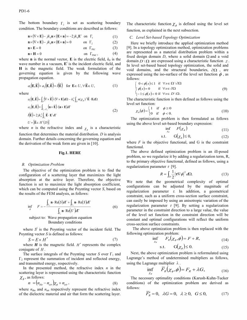
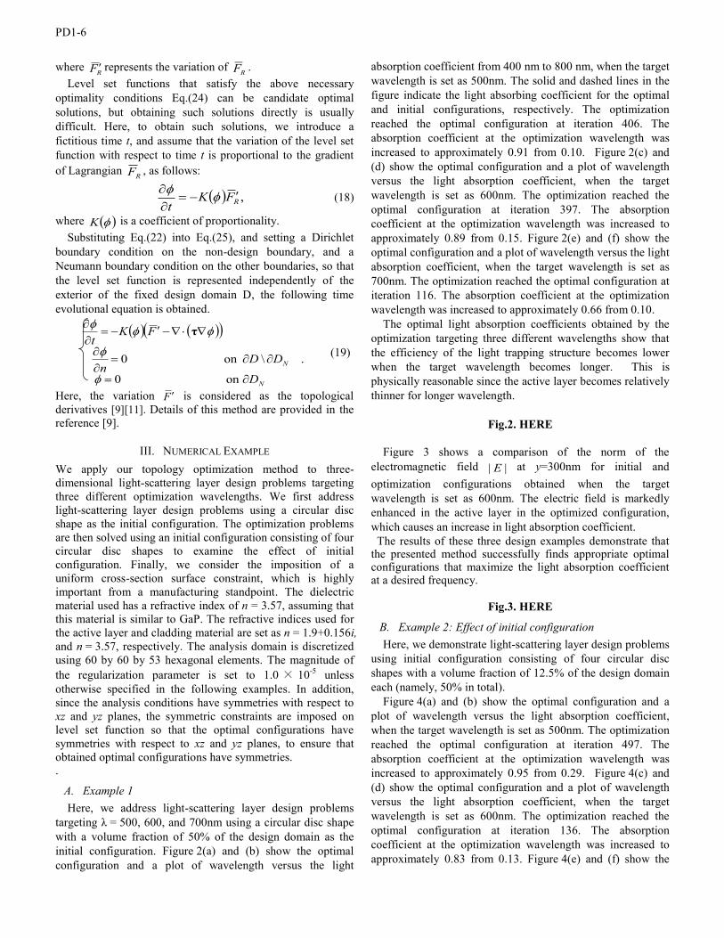
A. Light Scattering Layer Design Problem The design domain and boundary conditions of the solar cell model are shown in Fig. 1. A light-scattering layer is placed in contact with the upper surface of the topmost cladding layer of a pair of cladding layers that sandwich the active layer. Normal incident waves, where the electric field is polarized in x direction, enter the domain from the upper boundary, 1 . The left and right boundaries (yz-plane with x=0 and 600nm) are set as a perfect electric conductor (PEC), and the front and rear boundaries (xz-plane with y=0 and 600nm) are set as a perfect magnetic conductor (PMC), under a periodic condition.
T
Manuscript received June 28, 2013 (date on which paper was submitted for review). Corresponding author: Masaki Otomori (e-mail: [email protected]).
Digital Object Identifier inserted by IEEE
PD1-6
The bottom boundary 2 is set as scattering boundary
condition. The boundary conditions are described as follows:
,on0on0on0
on2
PMC
PEC
20
100
HnEn
nEnEnEnEnEn
jkjkjk i
(1)
(2)
(3)
(4) where n is the normal vector, E is the electric field, k0 is the wave number in a vacuum, Ei is the incident electric field, and H is the magnetic field. The weak formulation of the governing equation is given by the following wave propagation equation.
,~,for~~,~, 21 UUlaa EEEEEEE (1)
where
DHU
djkl
da
dnkda
i
D D
1
20
2
2201
~
~2~
~~,
~)(~~,
1
21
E
EEE
EnEnEE
EEEEEE
(2)
where n is the refractive index and is a characteristic
function that determines the material distribution. D is analysis domain. Further details concerning the governing equation and the derivation of the weak form are given in [10].
Fig.1. HERE
B. Optimization Problem The objective of the optimization problem is to find the
configuration of a scattering layer that maximizes the light absorption at the active layer. Therefore, the objective function is set to maximize the light absorption coefficient, which can be computed using the Poynting vector S, based on the results of the FEM analysis, as follows:
1
12
Re
ReReinf
dS
dSdSF
in
nn
(6)
subject to: Wave propagation equation Boundary conditions
where Si is the Poynting vector of the incident field. The Poynting vector S is defined as follows:
*HES (7) where H is the magnetic field. *H represents the complex
conjugate of H . The surface integrals of the Poynting vector S over Γ1 and
Γ2 represent the summation of incident and reflected energy, and transmitted energy, respectively.
In the presented method, the refractive index n in the scattering layer is represented using the characteristic function
, as follows: airairdie nnnn , (8)
where ndie and nair respectively represent the refractive index of the dielectric material and air that form the scattering layer.
The characteristic function is defined using the level set function, as explained in the next subsection.
C. Level Set-based Topology Optimization Here we briefly introduce the applied optimization method
[9]. In a topology optimization method, optimization problems are represented as a material distribution problem within a fixed design domain D, where a solid domain and a void domain \D are expressed using a characteristic function χ. In level set-based based topology optimization, the solid and void domains, and the structural boundaries, , are expressed using the iso-surface of the level set function , as follows:
010
10
xx
x
ififif
.\
\
Dxxx
(9)
The characteristic function is then defined as follows using the level set function:
0.if00if1
(10)
The optimization problem is then formulated as follows using the above level set-based boundary expression:
Finf (11) ,0G s.t. (12)
where F is the objective functional, and G is the constraint functional.
The above defined optimization problem is an ill-posed problem, so we regularize it by adding a regularization term, R, to the primary objective functional, defined as follows, using a regularization parameter [9].
.21 2
D
dR τ (13)
We note that the geometrical complexity of optimal configurations can be adjusted by the magnitude of regularization parameter . In addition, a geometrical constraint, such as a uniform cross-section surface constraint, can easily be imposed by using an anisotropic variation of the regularization parameter [9]. By setting a regularization parameter in the constraint direction to a large value, the value of the level set function in the constraint direction will be constant and optimal configurations will reflect the uniform cross-section surface constraints.
The above optimization problem is then replaced with the following optimization problem:
,,inf RFFR
(14)
.0G s.t. (15) Next, the above optimization problem is reformulated using
Lagrange’s method of undetermined multipliers as follows, using the Lagrange multiplier λ.
,,inf GFF RR
(16)
The necessary optimality conditions (Karush-Kuhn-Tucker conditions) of the optimization problem are derived as follows:
,0,0,0,0 GGFR (17)
PD1-6
where RF represents the variation of RF . Level set functions that satisfy the above necessary
optimality conditions Eq.(24) can be candidate optimal solutions, but obtaining such solutions directly is usually difficult. Here, to obtain such solutions, we introduce a fictitious time t, and assume that the variation of the level set function with respect to time t is proportional to the gradient of Lagrangian RF , as follows:
,RFKt
(18)
where K is a coefficient of proportionality. Substituting Eq.(22) into Eq.(25), and setting a Dirichlet
boundary condition on the non-design boundary, and a Neumann boundary condition on the other boundaries, so that the level set function is represented independently of the exterior of the fixed design domain D, the following time evolutional equation is obtained.
.
on0
\on0
N
N
D
DDn
FKt
τ
(19)
Here, the variation F is considered as the topological derivatives [9][11]. Details of this method are provided in the reference [9].
III. NUMERICAL EXAMPLE We apply our topology optimization method to three-dimensional light-scattering layer design problems targeting three different optimization wavelengths. We first address light-scattering layer design problems using a circular disc shape as the initial configuration. The optimization problems are then solved using an initial configuration consisting of four circular disc shapes to examine the effect of initial configuration. Finally, we consider the imposition of a uniform cross-section surface constraint, which is highly important from a manufacturing standpoint. The dielectric material used has a refractive index of n = 3.57, assuming that this material is similar to GaP. The refractive indices used for the active layer and cladding material are set as n = 1.9+0.156i, and n = 3.57, respectively. The analysis domain is discretized using 60 by 60 by 53 hexagonal elements. The magnitude of the regularization parameter is set to 1.0 × 10⁻⁵ unless otherwise specified in the following examples. In addition, since the analysis conditions have symmetries with respect to xz and yz planes, the symmetric constraints are imposed on level set function so that the optimal configurations have symmetries with respect to xz and yz planes, to ensure that obtained optimal configurations have symmetries. .
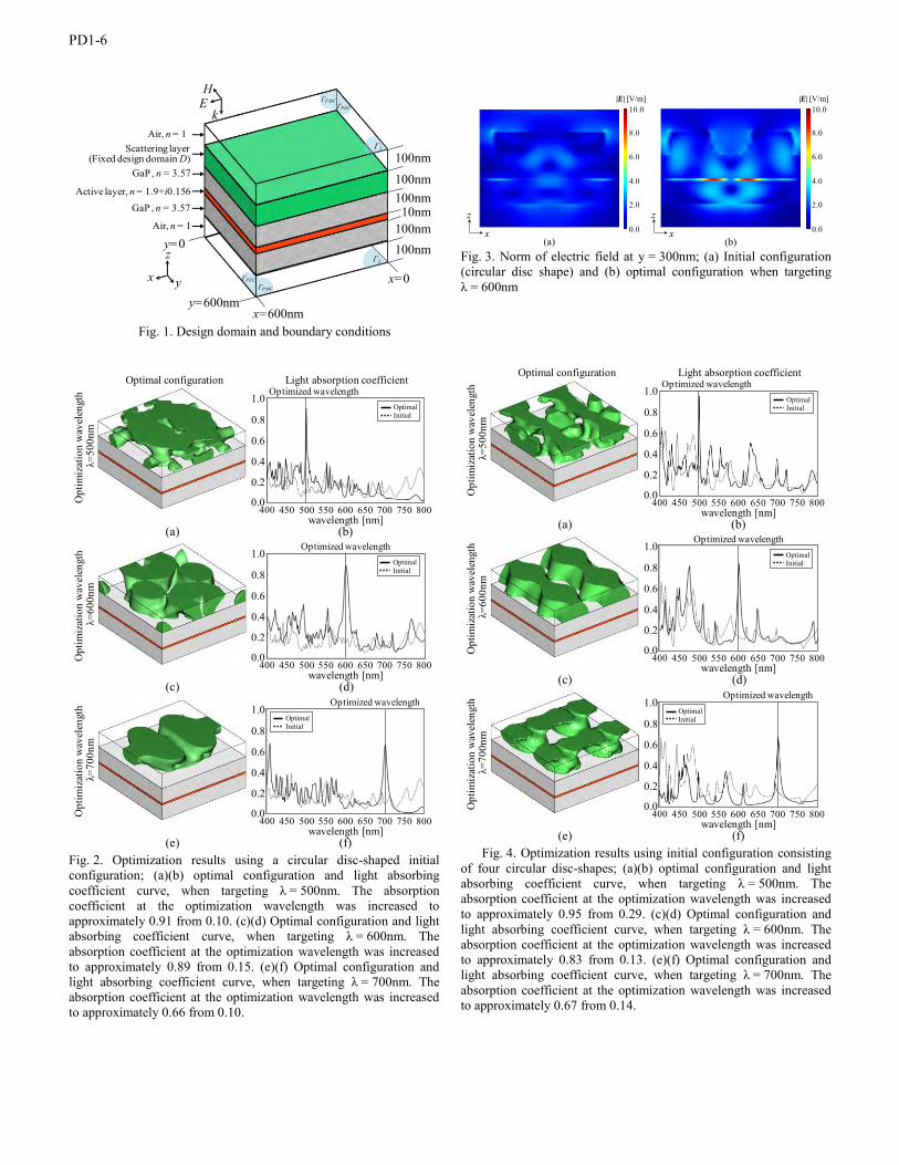
A. Example 1 Here, we address light-scattering layer design problems
targeting λ = 500, 600, and 700nm using a circular disc shape with a volume fraction of 50% of the design domain as the initial configuration. Figure 2(a) and (b) show the optimal configuration and a plot of wavelength versus the light
absorption coefficient from 400 nm to 800 nm, when the target wavelength is set as 500nm. The solid and dashed lines in the figure indicate the light absorbing coefficient for the optimal and initial configurations, respectively. The optimization reached the optimal configuration at iteration 406. The absorption coefficient at the optimization wavelength was increased to approximately 0.91 from 0.10. Figure 2(c) and (d) show the optimal configuration and a plot of wavelength versus the light absorption coefficient, when the target wavelength is set as 600nm. The optimization reached the optimal configuration at iteration 397. The absorption coefficient at the optimization wavelength was increased to approximately 0.89 from 0.15. Figure 2(e) and (f) show the optimal configuration and a plot of wavelength versus the light absorption coefficient, when the target wavelength is set as 700nm. The optimization reached the optimal configuration at iteration 116. The absorption coefficient at the optimization wavelength was increased to approximately 0.66 from 0.10.
The optimal light absorption coefficients obtained by the optimization targeting three different wavelengths show that the efficiency of the light trapping structure becomes lower when the target wavelength becomes longer. This is physically reasonable since the active layer becomes relatively thinner for longer wavelength.
Fig.2. HERE
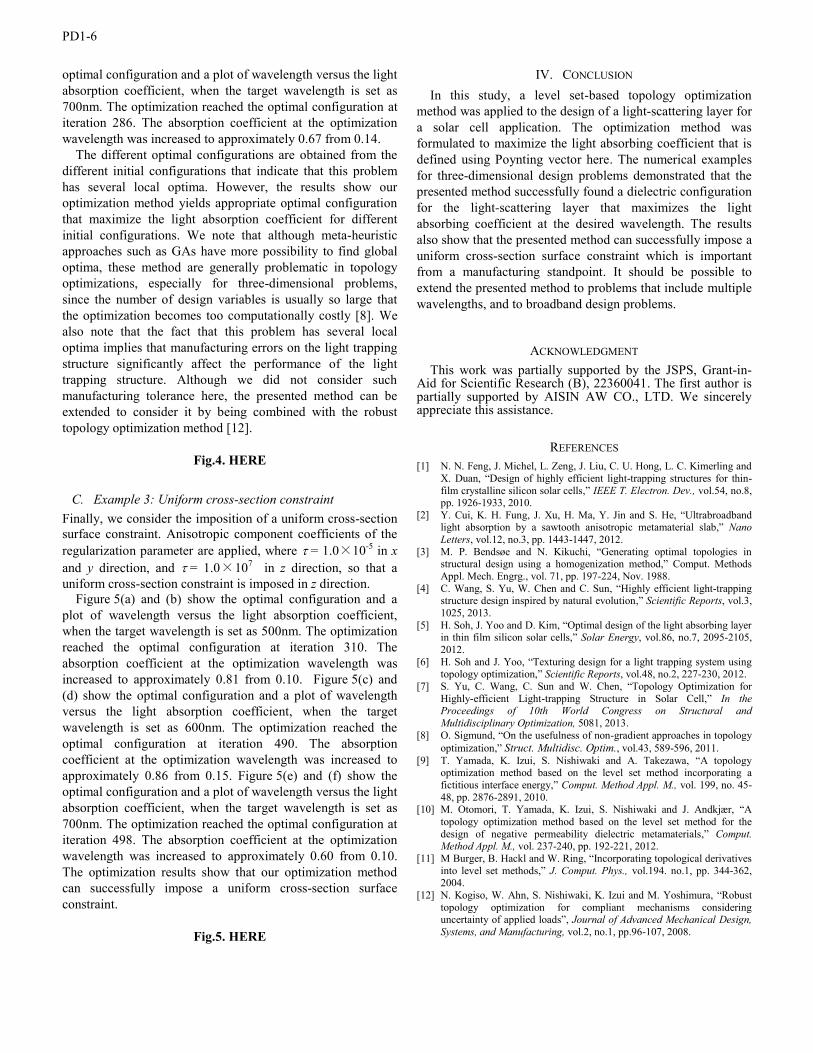
Figure 3 shows a comparison of the norm of the
electromagnetic field || E at y=300nm for initial and optimization configurations obtained when the target wavelength is set as 600nm. The electric field is markedly enhanced in the active layer in the optimized configuration, which causes an increase in light absorption coefficient.
The results of these three design examples demonstrate that the presented method successfully finds appropriate optimal configurations that maximize the light absorption coefficient at a desired frequency.
Fig.3. HERE
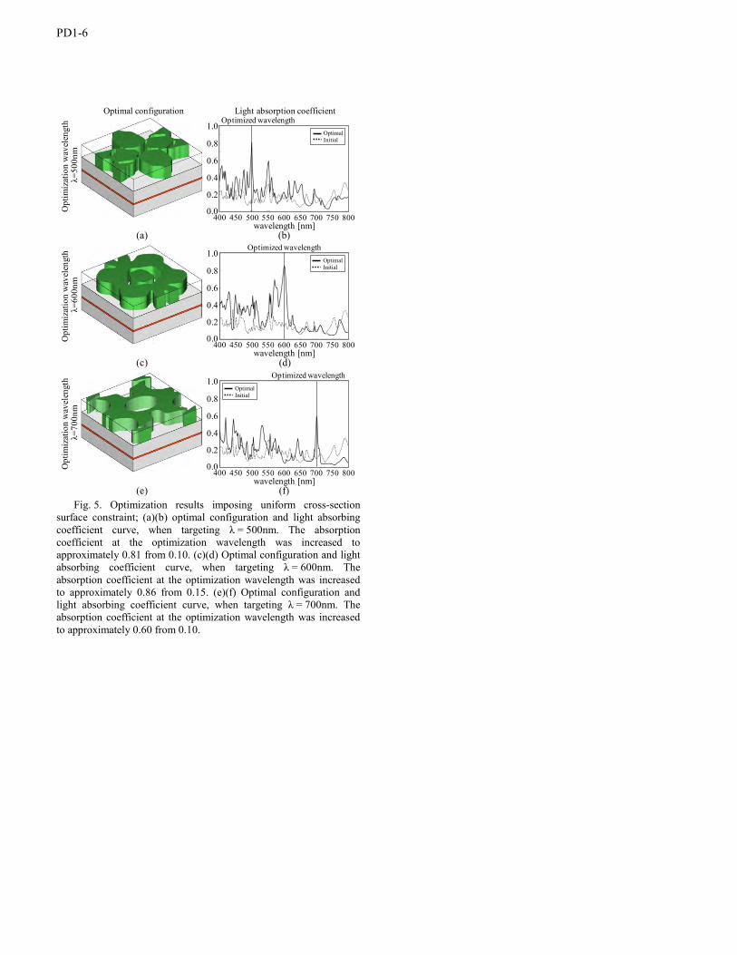
B. Example 2: Effect of initial configuration Here, we demonstrate light-scattering layer design problems
using initial configuration consisting of four circular disc shapes with a volume fraction of 12.5% of the design domain each (namely, 50% in total).
Figure 4(a) and (b) show the optimal configuration and a plot of wavelength versus the light absorption coefficient, when the target wavelength is set as 500nm. The optimization reached the optimal configuration at iteration 497. The absorption coefficient at the optimization wavelength was increased to approximately 0.95 from 0.29. Figure 4(c) and (d) show the optimal configuration and a plot of wavelength versus the light absorption coefficient, when the target wavelength is set as 600nm. The optimization reached the optimal configuration at iteration 136. The absorption coefficient at the optimization wavelength was increased to approximately 0.83 from 0.13. Figure 4(e) and (f) show the
PD1-6
optimal configuration and a plot of wavelength versus the light absorption coefficient, when the target wavelength is set as 700nm. The optimization reached the optimal configuration at iteration 286. The absorption coefficient at the optimization wavelength was increased to approximately 0.67 from 0.14.
The different optimal configurations are obtained from the different initial configurations that indicate that this problem has several local optima. However, the results show our optimization method yields appropriate optimal configuration that maximize the light absorption coefficient for different initial configurations. We note that although meta-heuristic approaches such as GAs have more possibility to find global optima, these method are generally problematic in topology optimizations, especially for three-dimensional problems, since the number of design variables is usually so large that the optimization becomes too computationally costly [8]. We also note that the fact that this problem has several local optima implies that manufacturing errors on the light trapping structure significantly affect the performance of the light trapping structure. Although we did not consider such manufacturing tolerance here, the presented method can be extended to consider it by being combined with the robust topology optimization method [12].
Fig.4. HERE
C. Example 3: Uniform cross-section constraint Finally, we consider the imposition of a uniform cross-section surface constraint. Anisotropic component coefficients of the regularization parameter are applied, where = 1.0×10⁻⁵ in x and y direction, and = 1.0×10⁷ in z direction, so that a uniform cross-section constraint is imposed in z direction.
Figure 5(a) and (b) show the optimal configuration and a plot of wavelength versus the light absorption coefficient, when the target wavelength is set as 500nm. The optimization reached the optimal configuration at iteration 310. The absorption coefficient at the optimization wavelength was increased to approximately 0.81 from 0.10. Figure 5(c) and (d) show the optimal configuration and a plot of wavelength versus the light absorption coefficient, when the target wavelength is set as 600nm. The optimization reached the optimal configuration at iteration 490. The absorption coefficient at the optimization wavelength was increased to approximately 0.86 from 0.15. Figure 5(e) and (f) show the optimal configuration and a plot of wavelength versus the light absorption coefficient, when the target wavelength is set as 700nm. The optimization reached the optimal configuration at iteration 498. The absorption coefficient at the optimization wavelength was increased to approximately 0.60 from 0.10. The optimization results show that our optimization method can successfully impose a uniform cross-section surface constraint.
Fig.5. HERE
IV. CONCLUSION In this study, a level set-based topology optimization
method was applied to the design of a light-scattering layer for a solar cell application. The optimization method was formulated to maximize the light absorbing coefficient that is defined using Poynting vector here. The numerical examples for three-dimensional design problems demonstrated that the presented method successfully found a dielectric configuration for the light-scattering layer that maximizes the light absorbing coefficient at the desired wavelength. The results also show that the presented method can successfully impose a uniform cross-section surface constraint which is important from a manufacturing standpoint. It should be possible to extend the presented method to problems that include multiple wavelengths, and to broadband design problems.
ACKNOWLEDGMENT This work was partially supported by the JSPS, Grant-in-
Aid for Scientific Research (B), 22360041. The first author is partially supported by AISIN AW CO., LTD. We sincerely appreciate this assistance.
REFERENCES [1] N. N. Feng, J. Michel, L. Zeng, J. Liu, C. U. Hong, L. C. Kimerling and
X. Duan, “Design of highly efficient light-trapping structures for thin-film crystalline silicon solar cells,” IEEE T. Electron. Dev., vol.54, no.8, pp. 1926-1933, 2010.
[2] Y. Cui, K. H. Fung, J. Xu, H. Ma, Y. Jin and S. He, “Ultrabroadband light absorption by a sawtooth anisotropic metamaterial slab,” Nano Letters, vol.12, no.3, pp. 1443-1447, 2012.
[3] M. P. Bendsøe and N. Kikuchi, “Generating optimal topologies in structural design using a homogenization method,” Comput. Methods Appl. Mech. Engrg., vol. 71, pp. 197-224, Nov. 1988.
[4] C. Wang, S. Yu, W. Chen and C. Sun, “Highly efficient light-trapping structure design inspired by natural evolution,” Scientific Reports, vol.3, 1025, 2013.
[5] H. Soh, J. Yoo and D. Kim, “Optimal design of the light absorbing layer in thin film silicon solar cells,” Solar Energy, vol.86, no.7, 2095-2105, 2012.
[6] H. Soh and J. Yoo, “Texturing design for a light trapping system using topology optimization,” Scientific Reports, vol.48, no.2, 227-230, 2012.
[7] S. Yu, C. Wang, C. Sun and W. Chen, “Topology Optimization for Highly-efficient Light-trapping Structure in Solar Cell,” In the Proceedings of 10th World Congress on Structural and Multidisciplinary Optimization, 5081, 2013.
[8] O. Sigmund, “On the usefulness of non-gradient approaches in topology optimization,” Struct. Multidisc. Optim., vol.43, 589-596, 2011.
[9] T. Yamada, K. Izui, S. Nishiwaki and A. Takezawa, “A topology optimization method based on the level set method incorporating a fictitious interface energy,” Comput. Method Appl. M., vol. 199, no. 45-48, pp. 2876-2891, 2010.
[10] M. Otomori, T. Yamada, K. Izui, S. Nishiwaki and J. Andkjær, “A topology optimization method based on the level set method for the design of negative permeability dielectric metamaterials,” Comput. Method Appl. M., vol. 237-240, pp. 192-221, 2012.
[11] M Burger, B. Hackl and W. Ring, “Incorporating topological derivatives into level set methods,” J. Comput. Phys., vol.194. no.1, pp. 344-362, 2004.
[12] N. Kogiso, W. Ahn, S. Nishiwaki, K. Izui and M. Yoshimura, “Robust topology optimization for compliant mechanisms considering uncertainty of applied loads”, Journal of Advanced Mechanical Design, Systems, and Manufacturing, vol.2, no.1, pp.96-107, 2008.
PD1-6
Fig. 1. Design domain and boundary conditions
Fig. 2. Optimization results using a circular disc-shaped initial configuration; (a)(b) optimal configuration and light absorbing coefficient curve, when targeting λ = 500nm. The absorption coefficient at the optimization wavelength was increased to approximately 0.91 from 0.10. (c)(d) Optimal configuration and light absorbing coefficient curve, when targeting λ = 600nm. The absorption coefficient at the optimization wavelength was increased to approximately 0.89 from 0.15. (e)(f) Optimal configuration and light absorbing coefficient curve, when targeting λ = 700nm. The absorption coefficient at the optimization wavelength was increased to approximately 0.66 from 0.10.
Fig. 3. Norm of electric field at y = 300nm; (a) Initial configuration (circular disc shape) and (b) optimal configuration when targeting λ = 600nm
Fig. 4. Optimization results using initial configuration consisting
of four circular disc-shapes; (a)(b) optimal configuration and light absorbing coefficient curve, when targeting λ = 500nm. The absorption coefficient at the optimization wavelength was increased to approximately 0.95 from 0.29. (c)(d) Optimal configuration and light absorbing coefficient curve, when targeting λ = 600nm. The absorption coefficient at the optimization wavelength was increased to approximately 0.83 from 0.13. (e)(f) Optimal configuration and light absorbing coefficient curve, when targeting λ = 700nm. The absorption coefficient at the optimization wavelength was increased to approximately 0.67 from 0.14.
Scattering layer(Fixed design domain D)
Air, n = 1
GaP , n = 3.57
Active layer, n = 1.9+i0.156GaP , n = 3.57
Air, n = 1
x y
z
x=600nm
x=0
y=600nm
y=0 100nm
10nm100nm
100nm100nm
100nm
EH
k
Γ1
Γ2
ΓPEC
ΓPECΓPMC
ΓPMC
(b)
(c)
1.0
0.8
0.6
0.4
0.2
0.0400 450 500 550 600 650 700 750 800
wavelength [nm]
OptimalInitial
Optimized wavelength
(d)
(e)
1.0
0.8
0.6
0.4
0.2
0.0400 450 500 550 600 650 700 750 800
wavelength [nm]
Light absorption coefficient
OptimalInitial
Optimized wavelength
Optimal configuration
Opt
imiz
atio
n w
avel
engt
h λ=
500n
m
(f)
(a)
1.0
0.8
0.6
0.4
0.2
0.0400 450 500 550 600 650 700 750 800
wavelength [nm]
OptimalInitial
Optimized wavelength
Opt
imiz
atio
n w
avel
engt
h λ=
600n
mO
ptim
izat
ion
wav
elen
gth
λ=70
0nm
10.0
8.0
6.0
4.0
2.0
0.0
|E| [V/m]10.0
8.0
6.0
4.0
2.0
0.0
|E| [V/m]
(a) (b)x
z
x
z
(b)
(c)
1.0
0.8
0.6
0.4
0.2
0.0400 450 500 550 600 650 700 750 800
wavelength [nm]
OptimalInitial
Optimized wavelength
(d)
(e)
1.0
0.8
0.6
0.4
0.2
0.0400 450 500 550 600 650 700 750 800
wavelength [nm]
Light absorption coefficient
OptimalInitial
Optimized wavelength
Optimal configuration
Opt
imiz
atio
n w
avel
engt
h λ=
500n
m
(f)
(a)
1.0
0.8
0.6
0.4
0.2
0.0400 450 500 550 600 650 700 750 800
wavelength [nm]
OptimalInitial
Optimized wavelength
Opt
imiz
atio
n w
avel
engt
h λ=
600n
mO
ptim
izat
ion
wav
elen
gth
λ=70
0nm
PD1-6
Fig. 5. Optimization results imposing uniform cross-section
surface constraint; (a)(b) optimal configuration and light absorbing coefficient curve, when targeting λ = 500nm. The absorption coefficient at the optimization wavelength was increased to approximately 0.81 from 0.10. (c)(d) Optimal configuration and light absorbing coefficient curve, when targeting λ = 600nm. The absorption coefficient at the optimization wavelength was increased to approximately 0.86 from 0.15. (e)(f) Optimal configuration and light absorbing coefficient curve, when targeting λ = 700nm. The absorption coefficient at the optimization wavelength was increased to approximately 0.60 from 0.10.
(b)
(c)
1.0
0.8
0.6
0.4
0.2
0.0400 450 500 550 600 650 700 750 800
wavelength [nm]
OptimalInitial
Optimized wavelength
(d)
(e)
1.0
0.8
0.6
0.4
0.2
0.0400 450 500 550 600 650 700 750 800
wavelength [nm]
Light absorption coefficient
OptimalInitial
Optimized wavelength
Optimal configuration
Opt
imiz
atio
n w
avel
engt
h λ=
500n
m
(f)
(a)
1.0
0.8
0.6
0.4
0.2
0.0400 450 500 550 600 650 700 750 800
wavelength [nm]
OptimalInitial
Optimized wavelength
Opt
imiz
atio
n w
avel
engt
h λ=
600n
mO
ptim
izat
ion
wav
elen
gth
λ=70
0nm