Embed Size (px)
DESCRIPTION
US LHC ACCELERATOR PROJECT. Brookhaven - Fermilab - Berkeley. LHC-DFBX Shipping Specification Steve Virostek LBNL Presented at the DFBX RFP Review 23-24 October 2002, LBNL. Presentation Summary. Shipping Specification Details Introduction Description, Destination and Schedule - PowerPoint PPT Presentation
Citation preview
1
LHC-DFBX
Shipping Specification
Steve VirostekLBNL
Presented at theDFBX RFP Review
23-24 October 2002, LBNL
Brookhaven - Fermilab - Berkeley
US LHC ACCELERATOR PROJECT
2
Presentation Summary
Shipping Specification Details• Introduction• Description, Destination and Schedule• Crate Performance Requirements• Preparation for Shipping• Instrumentation• Shipping Crate Features• Acceptance Criteria
Shipping Load Analysis• Approach• Scope• Results
3
Shipping Spec Introduction
LBNL is designing 8 DFBX’s for LHC
Each feedbox shipped in its own fully enclosed crate• Shock and vibration protection, environmental control
Specification gives shipping crate design requirements• Hardware geometry, allowable accelerations, etc.
Fabrication vendor has all shipping responsibilities• Design and fabrication of crates• Arrangement and coordination of shipping• Schedule specified in the RFP Statement of Work• LBNL responsible for Customs clearance and duties (if any)
4
Description, Destination and Schedule
Shipment Description
• Eight boxes given by six LBNL top-level assembly drawings
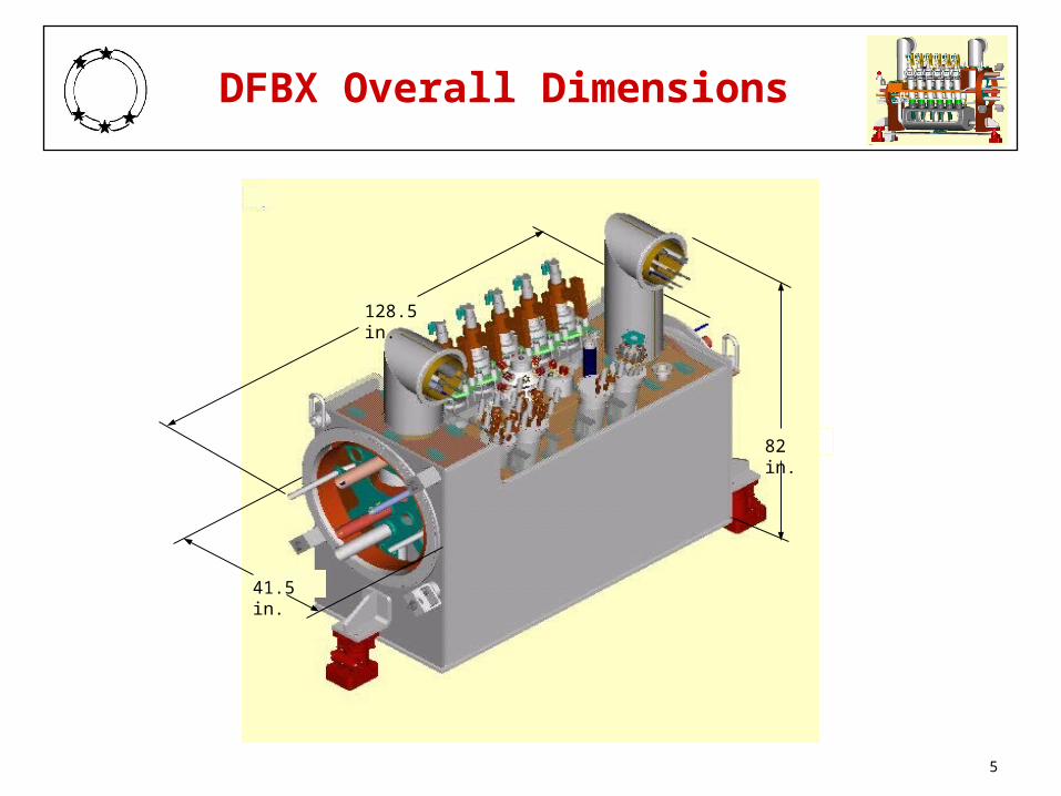
• Figure shows 3D model image with overall dimensions
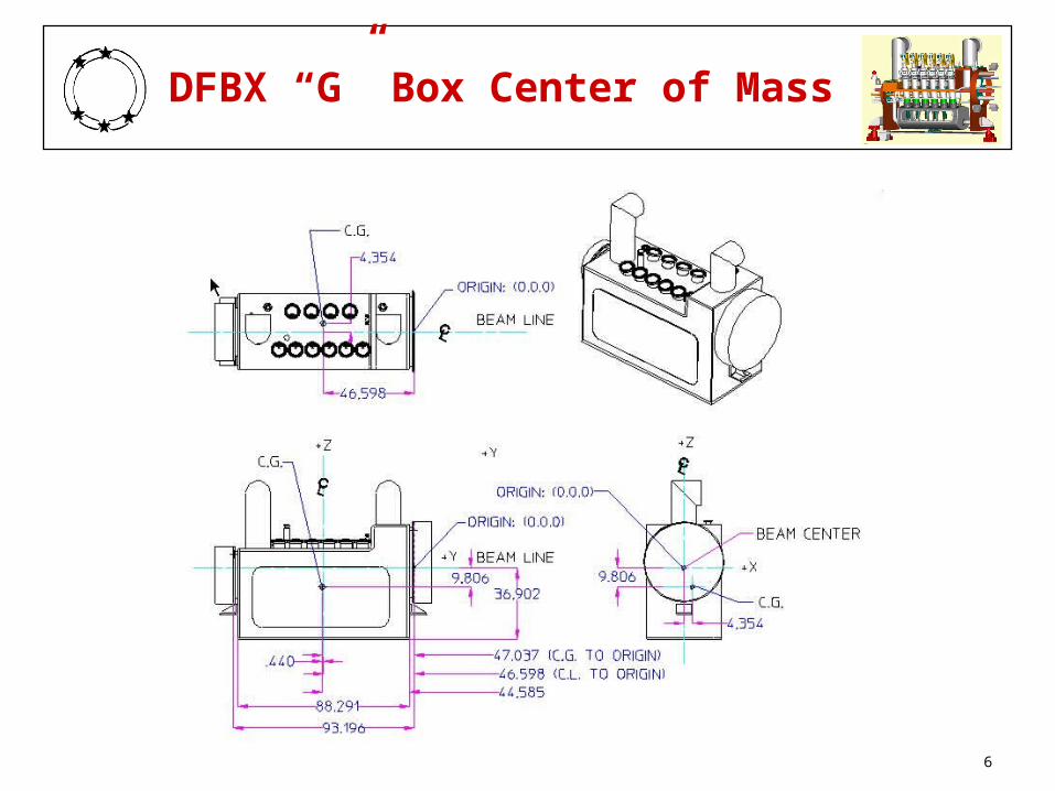
• Figure shows location of center of mass for DFBX “G” box
Destination and Shipping Dates
• Spec gives shipping address and contact at CERN
• Vendor chooses appropriate transport mode to meet schedule
• >1 feedbox in same shipment acceptable (separate crates)
• Feedboxes must satisfy the Acceptance Criteria Document (LBNL Engineering Spec M989) before and after shipping
5
DFBX Overall Dimensions
82 in.
128.5 in.
41.5 in.
6
DFBX “G” Box Center of Mass
7
Crate Performance Requirements
Analysis performed to determine DFBX tolerance to shock
• Details of analysis in LBNL Engineering Note M8043
Maximum vertical shock transmitted to feedbox: +5.0g
Maximum horizontal shock transmitted to feedbox: +2.0g
Fully loaded crate has a 1st mode >5 Hz and <10 Hz
Drop height requirement: 6” with <5 g’s transmitted to feedbox
Feedbox supported uniformly across bottom surface
• Jack mounting points not used for support within crate
8
Preparation for Shipping
Various DFBX components to be backfilled before shipping
• Described in Acceptance Criteria Document (Spec. M989)
Added supports used to restrain internal piping as required
• Installed through the feedbox end flanges
D1, Q3, JC1 and JC2 flange caps support ends of pipes
All other external piping restrained as appropriate
High current leads to be protected by covers or shields
• Prevents damage during loading/unloading
9
Shipping Crate Instrumentation
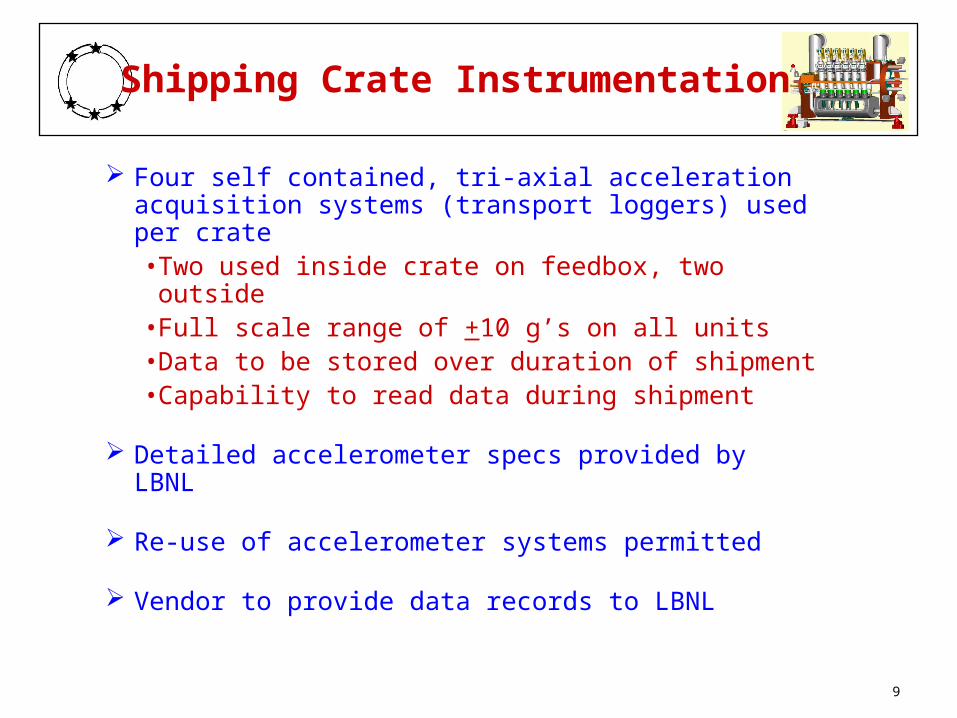
Four self contained, tri-axial acceleration acquisition systems (transport loggers) used per crate• Two used inside crate on feedbox, two outside• Full scale range of +10 g’s on all units• Data to be stored over duration of shipment• Capability to read data during shipment
Detailed accelerometer specs provided by LBNL
Re-use of accelerometer systems permitted
Vendor to provide data records to LBNL
10
Shipping Crate Features
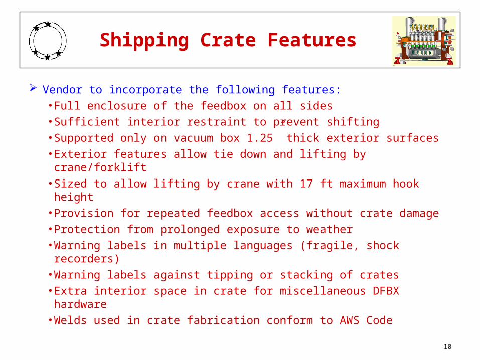
Vendor to incorporate the following features:
• Full enclosure of the feedbox on all sides
• Sufficient interior restraint to prevent shifting
• Supported only on vacuum box 1.25” thick exterior surfaces
• Exterior features allow tie down and lifting by crane/forklift
• Sized to allow lifting by crane with 17 ft maximum hook height
• Provision for repeated feedbox access without crate damage
• Protection from prolonged exposure to weather
• Warning labels in multiple languages (fragile, shock recorders)
• Warning labels against tipping or stacking of crates
• Extra interior space in crate for miscellaneous DFBX hardware
• Welds used in crate fabrication conform to AWS Code
11
Acceptance Criteria
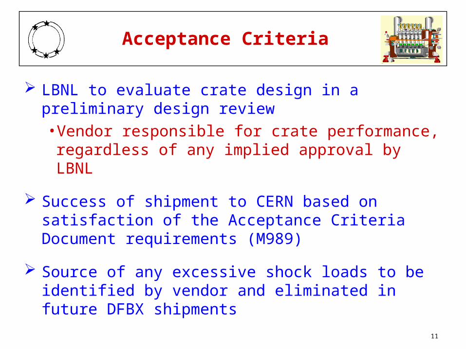
LBNL to evaluate crate design in a preliminary design review
• Vendor responsible for crate performance, regardless of any implied approval by LBNL
Success of shipment to CERN based on satisfaction of the Acceptance Criteria Document requirements (M989)
Source of any excessive shock loads to be identified by vendor and eliminated in future DFBX shipments
12
Analysis Approach
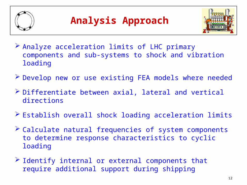
Analyze acceleration limits of LHC primary components and sub-systems to shock and vibration loading
Develop new or use existing FEA models where needed
Differentiate between axial, lateral and vertical directions
Establish overall shock loading acceleration limits
Calculate natural frequencies of system components to determine response characteristics to cyclic loading
Identify internal or external components that require additional support during shipping
13
Analysis Scope
Vacuum box including weight of internal components
Liquid helium vessel structure, supports and bellows
Thermal shield stresses and deflections
Surge tank supports including thrust bracket
High current leads (vapor cooled and HTS leads)
Bus duct free end support
Other internal pipes and external free ends
Pipe support spiders (Q3, D1, QRL and center spiders)
14
Analysis Results
Vacuum Box - stresses and vibrational modes from FEA model
• box stresses < allowable for10 g’s in any direction
• lowest vibrational mode: 22 Hz lateral (LHe vessel bellows)
• all other modes are >35 Hz
Helium Vessel - support loads & bellows deflections from FEA
• shipping loads minimal compared to test pressure (>10 g’s)
• tank supports: 8.6 g’s axial (lower support brackets), 10.4 g’s lateral (vert. suppt. buckling), 18 g’s vertical (struts)
• bellows limits of travel: 4.5 g’s lateral, 31 g’s axially, no limit vertically due to vertical struts
15
Analysis Results (continued)
High Current Leads• HTS lead cantilevered ends: >10 g’s in all dir. (G-10 sleeve)• HTS terminator ear:17 lb with 175 lb allowable force (~10 g)• vapor cooled leads:16” free length resulting in 32 g limit• vapor cooled leads deflect ~10 mils at ends under 1 g loading
Thermal Shield: FEA results for portions of thermal shield• stress limits: 12 g’s vertically, 5 g’s laterally
Surge Tank• 20 g vertical limit based on axial strength of G-10 supports• 3.5 g axial limit based on bending of G-10 supports• 12 g lateral limit based on tension and bending in supports