Embed Size (px)
DESCRIPTION
light pipe design
Citation preview
Light Guide TechniquesUsing LED LampsApplication Brief I-003
What Is a Light Guide?A light guide is a device designedto transport light from a lightsource to a point at some distancewith minimal loss. Light is trans-mitted through a light guide bymeans of total internal reflection.Light guides are usually made ofoptical grade materials such asacrylic resin, polycarbonate,epoxies, and glass. A light guidecan be used to transmit light froman LED lamp on a pc board to afront panel for use as statusindication, can be used to collectand direct light to backlight anLCD display or legend, and can beused as the means to illuminate agrid pattern on a see throughwindow. This Application Briefdiscusses the basics of simple lightguide design for these and otherpossible uses.
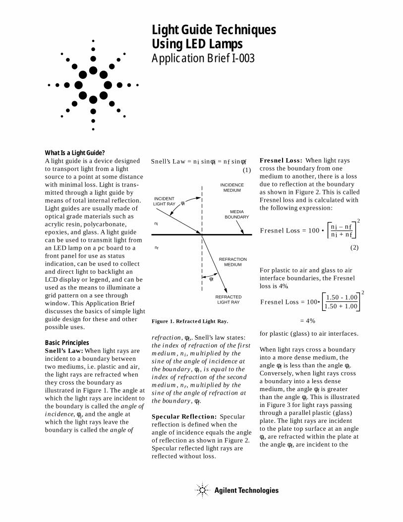
Basic PrinciplesSnell’s Law: When light rays areincident to a boundary betweentwo mediums, i.e. plastic and air,the light rays are refracted whenthey cross the boundary asillustrated in Figure 1. The angle atwhich the light rays are incident tothe boundary is called the angle of
incidence, φi, and the angle atwhich the light rays leave theboundary is called the angle of
Figure 1. Refracted Light Ray.
refraction, φf,. Snell’s law states:the index of refraction of the first
medium, ni, multiplied by the
sine of the angle of incidence at
the boundary, φi, is equal to the
index of refraction of the second
medium, nr, multiplied by the
sine of the angle of refraction at
the boundary, φf.
Specular Reflection: Specularreflection is defined when theangle of incidence equals the angleof reflection as shown in Figure 2.Specular reflected light rays arereflected without loss.
Fresnel Loss: When light rayscross the boundary from onemedium to another, there is a lossdue to reflection at the boundaryas shown in Figure 2. This is calledFresnel loss and is calculated withthe following expression:
(2)
When light rays cross a boundaryinto a more dense medium, theangle φf is less than the angle φi.Conversely, when light rays crossa boundary into a less densemedium, the angle φf is greaterthan the angle φi. This is illustratedin Figure 3 for light rays passingthrough a parallel plastic (glass)plate. The light rays are incidentto the plate top surface at an angleφi, are refracted within the plate atthe angle φf, are incident to the
For plastic to air and glass to airinterface boundaries, the Fresnelloss is 4%.
for plastic (glass) to air interfaces.
φi
φf
ni
nr
INCIDENCEMEDIUM
MEDIABOUNDARY
REFRACTIONMEDIUM
REFRACTEDLIGHT RAY
INCIDENTLIGHT RAY
Snell’s Law = ni sinφi = nf sinφf (1)
ni – nf ni + nf
Fresnel Loss = 100 •2
1.50 - 1.001.50 + 1.00
Fresnel Loss = 100•2
= 4%
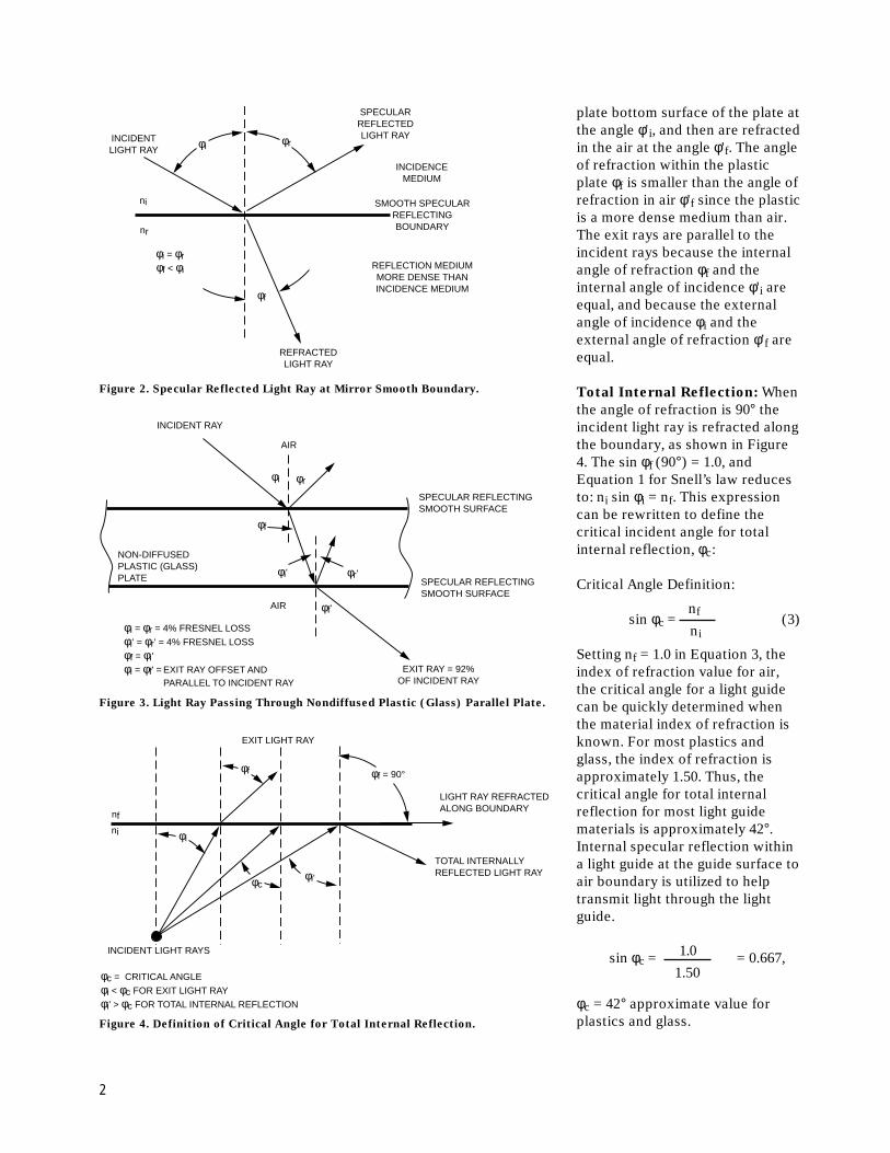
plate bottom surface of the plate atthe angle φ'i, and then are refractedin the air at the angle φ'f. The angleof refraction within the plasticplate φf is smaller than the angle ofrefraction in air φ'f since the plasticis a more dense medium than air.The exit rays are parallel to theincident rays because the internalangle of refraction φf and theinternal angle of incidence φ'i areequal, and because the externalangle of incidence φi and theexternal angle of refraction φ'f areequal.
Total Internal Reflection: Whenthe angle of refraction is 90° theincident light ray is refracted alongthe boundary, as shown in Figure4. The sin φf (90°) = 1.0, andEquation 1 for Snell’s law reducesto: ni sin φi = nf. This expressioncan be rewritten to define thecritical incident angle for totalinternal reflection, φc:
Critical Angle Definition:
sin φc = (3)
Setting nf = 1.0 in Equation 3, theindex of refraction value for air,the critical angle for a light guidecan be quickly determined whenthe material index of refraction isknown. For most plastics andglass, the index of refraction isapproximately 1.50. Thus, thecritical angle for total internalreflection for most light guidematerials is approximately 42°.Internal specular reflection withina light guide at the guide surface toair boundary is utilized to helptransmit light through the lightguide.
Figure 2. Specular Reflected Light Ray at Mirror Smooth Boundary.
Figure 3. Light Ray Passing Through Nondiffused Plastic (Glass) Parallel Plate.
Figure 4. Definition of Critical Angle for Total Internal Reflection.
nf
ni
φi φr
φf
ni
nr
INCIDENCEMEDIUM
SMOOTH SPECULARREFLECTINGBOUNDARY
REFRACTEDLIGHT RAY
INCIDENTLIGHT RAY
SPECULARREFLECTEDLIGHT RAY
REFLECTION MEDIUMMORE DENSE THANINCIDENCE MEDIUM
φi = φrφf < φi
φi
φi'
φr
φr'
φf
φf'
AIR
AIR
φi = φr = 4% FRESNEL LOSS
φi' = φr' = 4% FRESNEL LOSS
φf = φi'
φi = φf' = EXIT RAY OFFSET ANDPARALLEL TO INCIDENT RAY
INCIDENT RAY
NON-DIFFUSEDPLASTIC (GLASS)PLATE
SPECULAR REFLECTINGSMOOTH SURFACE
SPECULAR REFLECTINGSMOOTH SURFACE
EXIT RAY = 92%OF INCIDENT RAY
φc = CRITICAL ANGLE
φi < φc FOR EXIT LIGHT RAY
φi' > φc FOR TOTAL INTERNAL REFLECTION
φf
φcφi'
φi
φf = 90°
LIGHT RAY REFRACTEDALONG BOUNDARY
TOTAL INTERNALLYREFLECTED LIGHT RAY
INCIDENT LIGHT RAYS
EXIT LIGHT RAY
nf
ni
φc = 42° approximate value forplastics and glass.
sin φc = = 0.667,1.50
1.0
2
Light rays internal to a light guideincident to guide surface to airboundary are total internallyreflected when the angle ofincidence is 42° or greater. Havingthe critical angle being slightly lessthan 45° for most light guidematerials is very convenientbecause it allows the use of 45°reflecting prism surfaces in lightguide designs.
Ray Tracing: Ray tracing is atechnique used to predict the pathof light rays into, through, and outof a light guide. The principles ofSnell’s law, Fresnel loss, andspecular reflection are applied ateach guide surface to air interfaceto determine the direction of thelight ray. Ray tracing is used in thisApplication Brief to illustrate theperformance of light guide designs.
Light Guide DesignThere are three design issues to beexamined when designing a lightguide:1) effective flux coupling to get the
light from an LED lamp into thelight guide with minimal loss,
2) transmitting the light throughthe guide to the exit surface, and
3) allowing the light to escapethrough the exit surface withminimal loss.
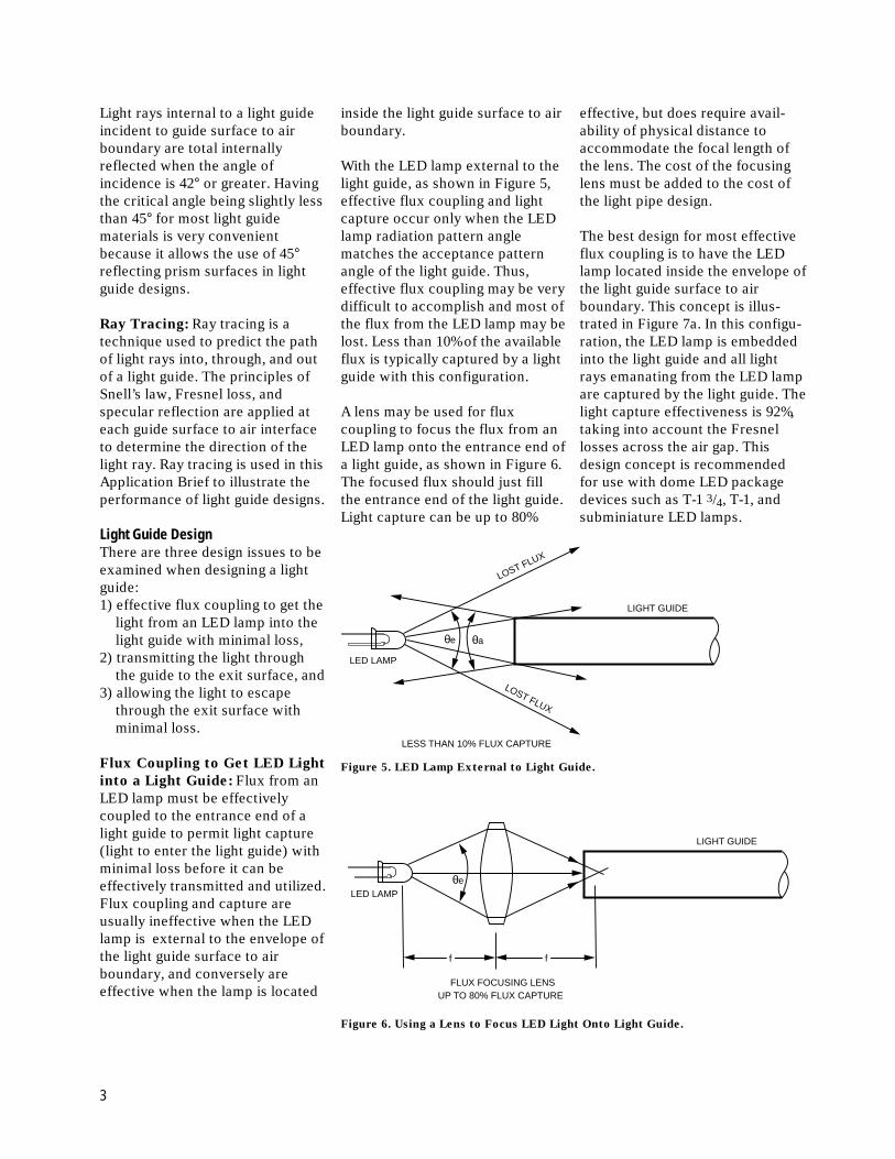
Flux Coupling to Get LED Light
into a Light Guide: Flux from anLED lamp must be effectivelycoupled to the entrance end of alight guide to permit light capture(light to enter the light guide) withminimal loss before it can beeffectively transmitted and utilized.Flux coupling and capture areusually ineffective when the LEDlamp is external to the envelope ofthe light guide surface to airboundary, and conversely areeffective when the lamp is located
inside the light guide surface to airboundary.
With the LED lamp external to thelight guide, as shown in Figure 5,effective flux coupling and lightcapture occur only when the LEDlamp radiation pattern anglematches the acceptance patternangle of the light guide. Thus,effective flux coupling may be verydifficult to accomplish and most ofthe flux from the LED lamp may belost. Less than 10% of the availableflux is typically captured by a lightguide with this configuration.
A lens may be used for fluxcoupling to focus the flux from anLED lamp onto the entrance end ofa light guide, as shown in Figure 6.The focused flux should just fillthe entrance end of the light guide.Light capture can be up to 80%
effective, but does require avail-ability of physical distance toaccommodate the focal length ofthe lens. The cost of the focusinglens must be added to the cost ofthe light pipe design.
The best design for most effectiveflux coupling is to have the LEDlamp located inside the envelope ofthe light guide surface to airboundary. This concept is illus-trated in Figure 7a. In this configu-ration, the LED lamp is embeddedinto the light guide and all lightrays emanating from the LED lampare captured by the light guide. Thelight capture effectiveness is 92%,taking into account the Fresnellosses across the air gap. Thisdesign concept is recommendedfor use with dome LED packagedevices such as T-1 3/4, T-1, andsubminiature LED lamps.
LOST FLUX
LOST FLUX
LIGHT GUIDE
LESS THAN 10% FLUX CAPTURE
LED LAMP
θe θa
Figure 5. LED Lamp External to Light Guide.
Figure 6. Using a Lens to Focus LED Light Onto Light Guide.
LIGHT GUIDE
UP TO 80% FLUX CAPTUREFLUX FOCUSING LENS
LED LAMPθe
f f
3
When the LED lamp package isglued into the light guide with anoptical grade epoxy, as shown inFigure 7b, the epoxy package ofthe lamp optically disappears dueto the elimination of Fresnellosses, and the flux capture isessentially 100%. In most lightguide applications, using epoxy toglue the LED lamp to the lightguide to eliminate air gap Fresnelloss is neither practical nornecessary. All of the suggestedlight guide designs presented inthis Application Brief assume thereis an air gap between the LEDlamp and the light guide.
Physical Attributes of a Light
Guide: The exterior surfacefinishes of a light guide are impor-tant to assure proper operation, asshown in Figure 8. The sidesparallel to the direction of lighttravel should be smooth, like amirror, to affect total internalreflection. They may be paintedwith a white light reflecting paintto reflect those diagonal rays lessthan the critical angle that mayotherwise escape. The entranceend should be smooth, contoured
LIGHT GUIDE
8% FRESNEL LOSSIN AIR GAP
92% FLUX CAPTURE
LED LAMP
LIGHT GUIDE
LED EMITTER EPOXIED INTOLIGHT GUIDE TO ELIMINATE AIR GAP = NO FRESNEL LOSS
100% FLUX CAPTURE
LED LAMP
Figure 7a. LED Lamp Located Inside a Light Guide for Best Flux Coupling.
Figure 7b. LED Lamp Epoxied into a Light Guide to Eliminate Fresnel Loss.
SMOOTH FLAT OR CONCAVECONTOURED SURFACE TOMATCH LED LAMP
LIGHT GUIDE
DIFFUSED EXITSURFACE
ROUNDED CORNERS0.5 mm (0.020 IN.)MINIMUM RADIUS
SMOOTH (MIRROR)EXTERIOR SURFACE
OPTIONAL WHITE LIGHTREFLECTING PAINT
ON EXTERIOR SURFACE
to match the LED lamp device foreffective light capture, allowinglight rays to enter the light guidewith minimal reflection andscatter. The exit end should bediffused. A diffused exit end hasrandom critical angles acrossits surface providing a highprobability light rays can escape,and also scatters the light raysproducing a wide radiation pat-tern.
Light guides may be made in anydesired shape, cylindrical (oval),
rectangular (square), conical(increasing in size from entranceend to exit end), or any specialshape (arrow, star shaped, quartermoon, etc.). For rectangular andspecial shapes, the corners shouldhave a radius greater than 0.5 mm(0.020 in.), not sharp, to assureillumination in the corners. Theshape of the light guide maygradually change along its length,i.e. from circular at the entranceend to accommodate the lamp, tosquare at the exit end, as shown inFigure 8.
Light Entrance End of Light
Guides for Various Types of
LED Devices: For effective fluxcoupling and light capture, the lightentrance end of a light guideshould be smooth and flat orconcave contoured to match thelight output radiation pattern andpackage configuration of themating LED lamp device.
For SMT LED lamp devices thathave a light emitting area that is aflat surface, the entrance end of thelight guide should be a smooth flatsurface. The entrance end of thelight guide should be placed overand in close proximity to the lightemitting surface of the SMT LEDlamp for effective flux coupling
Figure 8. The Basic Attributes of a Light Guide, shown with a change in shape
from Circular to Rectangular along its Length.
4
Figure 9. Light Guide with a Smooth
Flat Entrance End positioned over an
SMT LED Lamp.
Figure 10. A Light Guide with a Smooth Concave Entrance End increases Flux
Coupling and Light Capture from an SMT Chip LED Lamp.
and light capture, as illustrated inFigure 9. The entrance end of thelight guide needs to be slightlylarger than the emitting surface ofthe LED lamp to assure 92% fluxcapture, taking into account theFresnel losses across the air gap.
���
LIGHT GUIDE
SMT LED LAMP
PC BOARD
SMOOTH, FLATSURFACE
ENTRANCEEND
���SMT CHIP LED
PC BOARD
SMOOTH, CONCAVESURFACE INCREASES
FLUX CAPTURE
�
LIGHT GUIDE
20%-30% LOST FLUX
62%-72% FLUX CAPTURE
SMT Chip LED lamp packages arecubic in shape, diffused, allowinglight to emit from the sides as wellas the top. Only about 40% of thetotal available flux is emitted fromthe top. The other 60% is emittedfrom the side. Thus, only 40% ofthe light from an SMT Chip LEDlamp would be captured by a lightguide with a flat surface entranceend, the remaining flux is lost. Alight guide with a smooth concaveentrance end to fit over the SMTChip LED lamp is effective inincreasing flux capture, as shownin Figure 10. The smooth concavesurface enhances flux couplingand light capture by reducing thepossibility of a light ray intersect-ing the light guide at the criticalangle and being reflected. With theconcave entrance end, about 70%to 80% of the available emitted fluxfrom an SMT Chip LED is capturedby the light guide, and the lightloss is reduced to 20% to 30%.
This concave contoured entranceend technique may be used withany light guide/LED lamp combina-tion to enhance flux coupling and
light capture. In Figure 11, a “Yoke”lead SMT subminiature lamp isused to illuminate a light guidelocated at the back side of a pcboard. The lamp is located in athrough hole and surface mountedon the component side of theboard. The smooth concavesurface entrance end of the lightguide captures more of the radi-ated flux from the LED lamp thandoes a flat surface.
Figure 11. The Concave End of a Light
Guide Enhances Flux Coupling and
Light Capture From an Inverted
Surface Mounted “Yoke” Lead SMT
Subminiature LED Lamp.
As a minimum insertion distancefor positive flux coupling and lightcapture, standard T-1 3/4 untinted,nondiffused LED lamps should beinserted into the entrance end of alight guide up to the LED reflectorcup, located within the lamppackage, as shown in Figure 12.This assures 92% flux capture,taking into account the Fresnelloss across the air gap between thelamp dome and light guide. Forbest performance, insertion to thebase flange on the lamp package isrecommended. For T-1 3/4 LED
���
CONCAVE SMOOTHSURFACE ENHANCES
FLUX CAPTURE
“YOKE” LEAD SMTSUBMINIATURE LED LAMP
PC BOARD
LIGHT GUIDE
5
lamps, the lamp acceptance holeshould be 5.33 mm (0.210 in.) to5.59 mm (0.220 in.) in diameter.The end of the hole should be asmooth spherical dome radius. Thehole should be at least 5.33mm (0.210 in.) in depth for mini-mum length insertion, and 8.31 mm(0.327 in.) minimum in depth forfull length insertion. For T-1 LEDlamps, the lamp acceptance holediameter should be 3.30 mm (0.130in.) to 3.43 mm (0.135 in.) indiameter. Only full length insertionto the lamp base flange is recom-mended for T-1 lamps to achieveeffective flux coupling and cap-ture, with a minimum hole depth of2.165 mm (0.085 in.).
LED light bars may also be used aslight sources for light guides.These devices that have a lightemitting area that is a large flatsurface. Therefore, for effectiveflux coupling and light capture theentrance end of the light guideshould be a smooth flat surface,placed over and in close proximityto the light emitting surface ofthe LED light bar, as illustrated inFigure 13. The entrance end of the
Figure 12. Insertion of T-1 3/4 and T-1 Untinted, Nondiffused LED Lamps
into the Entrance End of a Light Guide for Effective Flux Coupling.
���PC BOARD
5727-13 AB I-003
92% FLUX CAPTURE
LIGHT GUIDE
SMOOTH, FLATSURFACE
ENTRANCE END
LEDLIGHT BAR
light guide needs to be slightlylarger than the emitting surface ofthe light bar to assure 92% fluxcapture, taking into account theFresnel losses across the air gap.
Diffused Exit End of a Light
Guide: A diffused exit end pre-sents random critical angles tointernal light rays, assuring theprobability of light escaping from a
light guide. This may also beviewed as the diffused exit endhaving random indices of refrac-tion. The exiting light rays aredisbursed at random angles into awide radiation pattern of light, asshown in Figure 14.
Figure 13. Light Guide with a Smooth Flat Entrance End Positioned Over an LED
Light Bar for Best Flux Coupling.
LIGHT GUIDELIGHT GUIDE
92% FLUX CAPTURE
SMOOTH INTERIORSURFACE FOR LED
LAMP AT ENTRANCE END
T-1 3/4, T-1 LED LAMPT-1 3/4 LED LAMP
RECOMMENDED INSERTIONOF LAMP TO FLANGE ATBASE OF LAMP PACKAGE
MINIMUM INSERTIONFOR T-1 3/4 LAMP TOLED REFLECTOR CUP
6
Figure 14. Diffused Exit End Enhances the Probability of Light Escaping from a
Light Guide.
LIGHT GUIDE
LIGHT RAYS ARE DISBURSEDINTO A WIDE RADIATIONPATTERN
LED LAMPDIFFUSED EXIT SURFACEENHANCES THE PROBABILITYOF LIGHT RAYS ESCAPING
Light Guides Around Corners
Light guides may be bent to goaround corners. The bend radiusshould be equal to or greater thantwo thicknesses or twice thediameter of the light guide tominimize light loss. The light rayreflections follow the smoothcontour of the radius bend withoutloss, as shown in Figure 15. Sharpright angle direction changes maybe achieved by using a reflectiveprism design in the light guide atthe 90° bend location, as shown inFigure 16.
DIAMETER OR THICKNESS
LED LAMP
LIGHT GUIDE
LIGHT RAYREFLECTIONSFOLLOWCURVATURE OFLIGHT GUIDE
MINIMUM BEND RADIUS =2X DIAMETER OR THICKNESS
Figure 15. Light Guide with a 90° Bend. Light Rays are Scattered by Diffused Exit
End.
Figure 16. Light Guide with Built in 45° Prism Reflector.����
LIGHT GUIDE
SMT LED LAMP
PC BOARD
45° REFLECTIVEPRISM SURFACE
7
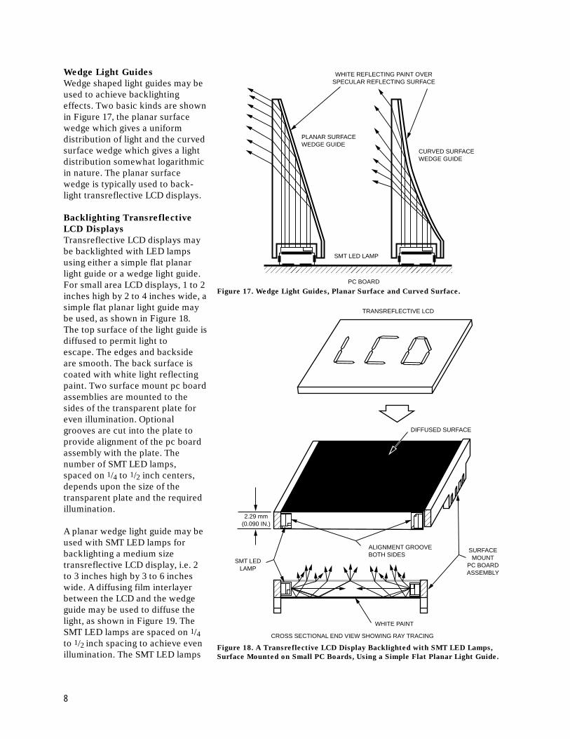
Wedge Light Guides
Wedge shaped light guides may beused to achieve backlightingeffects. Two basic kinds are shownin Figure 17, the planar surfacewedge which gives a uniformdistribution of light and the curvedsurface wedge which gives a lightdistribution somewhat logarithmicin nature. The planar surfacewedge is typically used to back-light transreflective LCD displays.
Backlighting Transreflective
LCD Displays
Transreflective LCD displays maybe backlighted with LED lampsusing either a simple flat planarlight guide or a wedge light guide.For small area LCD displays, 1 to 2inches high by 2 to 4 inches wide, asimple flat planar light guide maybe used, as shown in Figure 18.The top surface of the light guide isdiffused to permit light toescape. The edges and backsideare smooth. The back surface iscoated with white light reflectingpaint. Two surface mount pc boardassemblies are mounted to thesides of the transparent plate foreven illumination. Optionalgrooves are cut into the plate toprovide alignment of the pc boardassembly with the plate. Thenumber of SMT LED lamps,spaced on 1/4 to 1/2 inch centers,depends upon the size of thetransparent plate and the requiredillumination.
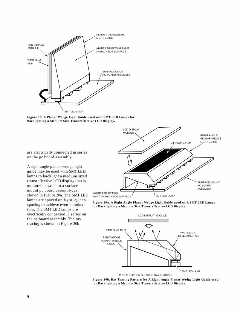
A planar wedge light guide may beused with SMT LED lamps forbacklighting a medium sizetransreflective LCD display, i.e. 2to 3 inches high by 3 to 6 incheswide. A diffusing film interlayerbetween the LCD and the wedgeguide may be used to diffuse thelight, as shown in Figure 19. TheSMT LED lamps are spaced on 1/4to 1/2 inch spacing to achieve evenillumination. The SMT LED lamps
Figure 18. A Transreflective LCD Display Backlighted with SMT LED Lamps,
Surface Mounted on Small PC Boards, Using a Simple Flat Planar Light Guide.
Figure 17. Wedge Light Guides, Planar Surface and Curved Surface.����SMT LED LAMP
WHITE REFLECTING PAINT OVERSPECULAR REFLECTING SURFACE
PLANAR SURFACEWEDGE GUIDE
CURVED SURFACEWEDGE GUIDE
PC BOARD
��
��
��
TRANSREFLECTIVE LCD
DIFFUSED SURFACE
SURFACEMOUNT
PC BOARDASSEMBLY
ALIGNMENT GROOVEBOTH SIDES
2.29 mm(0.090 IN.)
SMT LEDLAMP
WHITE PAINT
CROSS SECTIONAL END VIEW SHOWING RAY TRACING
8
are electrically connected in serieson the pc board assembly.
A right angle planar wedge lightguide may be used with SMT LEDlamps to backlight a medium sizedtransreflective LCD display that ismounted parallel to a surfacemount pc board assembly, asshown in Figure 20a. The SMT LEDlamps are spaced on 1/4 to 1/2 inchspacing to achieve even illumina-tion. The SMT LED lamps areelectrically connected in series onthe pc board assembly. The raytracing is shown in Figure 20b.
Figure 19. A Planar Wedge Light Guide used with SMT LED Lamps for
Backlighting a Medium Size Transreflective LCD Display.
SURFACE MOUNTPC BOARD ASSEMBLY
WHITE REFLECTING PAINTON BACKSIDE SURFACE
PLANAR TRIANGULARLIGHT GUIDE
LCD DISPLAYMODULE
DIFFUSINGFILM
SMT LED LAMP
Figure 20a. A Right Angle Planar Wedge Light Guide used with SMT LED Lamps
for Backlighting a Medium Size Transreflective LCD Display.
Figure 20b. Ray Tracing Pattern for A Right Angle Planar Wedge Light Guide used
for Backlighting a Medium Size Transreflective LCD Display.
LCD DISPLAYMODULE
RIGHT ANGLEPLANAR WEDGELIGHT GUIDEDIFFUSING FILM
SURFACE MOUNTPC BOARDASSEMBLY
SMT LED LAMPWHITE REFLECTINGPAINT ON BACKSIDE SURFACE
LCD DISPLAY MODULE
RIGHT ANGLEPLANAR WEDGE
GUIDE
DIFFUSING FILMWHITE LIGHT
REFLECTING PAINT
SMT LED LAMPCROSS SECTION SHOWING RAY TRACING
9
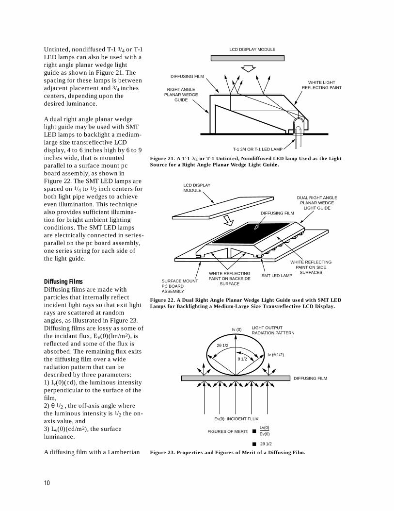
Untinted, nondiffused T-1 3/4 or T-1LED lamps can also be used with aright angle planar wedge lightguide as shown in Figure 21. Thespacing for these lamps is betweenadjacent placement and 3/4 inchescenters, depending upon thedesired luminance.
A dual right angle planar wedgelight guide may be used with SMTLED lamps to backlight a medium-large size transreflective LCDdisplay, 4 to 6 inches high by 6 to 9inches wide, that is mountedparallel to a surface mount pcboard assembly, as shown inFigure 22. The SMT LED lamps arespaced on 1/4 to 1/2 inch centers forboth light pipe wedges to achieveeven illumination. This techniquealso provides sufficient illumina-tion for bright ambient lightingconditions. The SMT LED lampsare electrically connected in series-parallel on the pc board assembly,one series string for each side ofthe light guide.
Diffusing FilmsDiffusing films are made withparticles that internally reflectincident light rays so that exit lightrays are scattered at randomangles, as illustrated in Figure 23.Diffusing films are lossy as some ofthe incidant flux, Ev(0)(lm/m2), isreflected and some of the flux isabsorbed. The remaining flux exitsthe diffusing film over a wideradiation pattern that can bedescribed by three parameters:1) Iv(0)(cd), the luminous intensityperpendicular to the surface of thefilm,2) θ 1/2 , the off-axis angle wherethe luminous intensity is 1/2 the on-axis value, and3) Lv(0)(cd/m2), the surfaceluminance.
A diffusing film with a Lambertian
Figure 21. A T-1 3/4 or T-1 Untinted, Nondiffused LED lamp Used as the Light
Source for a Right Angle Planar Wedge Light Guide.
Figure 22. A Dual Right Angle Planar Wedge Light Guide used with SMT LED
Lamps for Backlighting a Medium-Large Size Transreflective LCD Display.
Figure 23. Properties and Figures of Merit of a Diffusing Film.
RIGHT ANGLEPLANAR WEDGE
GUIDE
DIFFUSING FILMWHITE LIGHT
REFLECTING PAINT
LCD DISPLAY MODULE
T-1 3/4 OR T-1 LED LAMP
LCD DISPLAYMODULE
DUAL RIGHT ANGLEPLANAR WEDGE
LIGHT GUIDE
SURFACE MOUNTPC BOARDASSEMBLY
SMT LED LAMP
WHITE REFLECTINGPAINT ON SIDE
SURFACESWHITE REFLECTINGPAINT ON BACKSIDE
SURFACE
DIFFUSING FILM
Iv (0) LIGHT OUTPUTRADIATION PATTERN
Iv (θ 1/2)
2θ 1/2
2θ 1/2
θ 1/2
DIFFUSING FILM
Ev(0): INCIDENT FLUX
FIGURES OF MERIT:Lv(0)
Ev(0)
10
radiation pattern has a θ 1/2 valueof 60 degrees, and is the maximumviewing angle performance thatcan be achieved with a diffuser.
Figures of merit for comparing onediffusing film with another are:
• Lv(0)(cd/m2)/Ev(0)(lm/m2) =The ratio of on-axis luminanceto incidant flux.
Where: Lv(0)(cd/m2) =Iv(0)(cd)/A(m2), andA(m2) = a selected area of
the diffusing film surface.
• 2θ 1/2 = The viewing cone angle.
Using these figure of merit param-eters, a trade-off between outputluminance and radiation patternmust then be made in selecting adiffusing film in order to achievedesired overall illuminationperformance in combination with alight guide. The higher the value ofthe Lv(0)/Ev(0) ratio, the brighteris the output luminance throughthe diffusing film for illuminatingan LCD display. Also, the wider isthe 2θ 1/2 angle, the better will bethe output radiation pattern(viewing cone angle) from thediffusing film, reducing the chanceof an LCD display appearingbrighter in the center than at theouter edges. The following compa-nies supply diffusing films:
Optical Systems
3M Safety and Security SystemsDivision, 3M Center, Building 225-4N-14St. Paul, MN 55144-100001-(800)-328-7098Products:Diffusion Films:
Type 100, 5 mils, 2θ 1/2 = 26°.Type 070, 10 mils, 2θ 1/2 = 32°.Type 050, 16 mils, 2θ 1/2 = 36°.Type 040, 20 mils, 2θ 1/2 = 40°
Brightness Enhancement Film
(BEF)
Miles, Inc.
Polymers DivisionMobay Road, Bldg. 8Pittsburgh, PA 15205-9741(412) 777-2000 FAX: (412) 777-2021Products: Makrofol BL 6-2:
a pigment filled polycarbonatefilm, 8 and 16 mil thicknesses,2θ 1/2 = 18° and 36°.Makrofol LT 6-4: a glass fiberfilled polycarbonate film, 16 to 20mil thicknesses, 2θ 1/2 = 16°.
Physical Optics Corporation
20600 Gramercy Place Bldg. 100Torrance, CA 90501(310) 320-3088 Fax: (310) 320-8067Products: Beam Homogenizing
Light Shaping Diffusing Films.
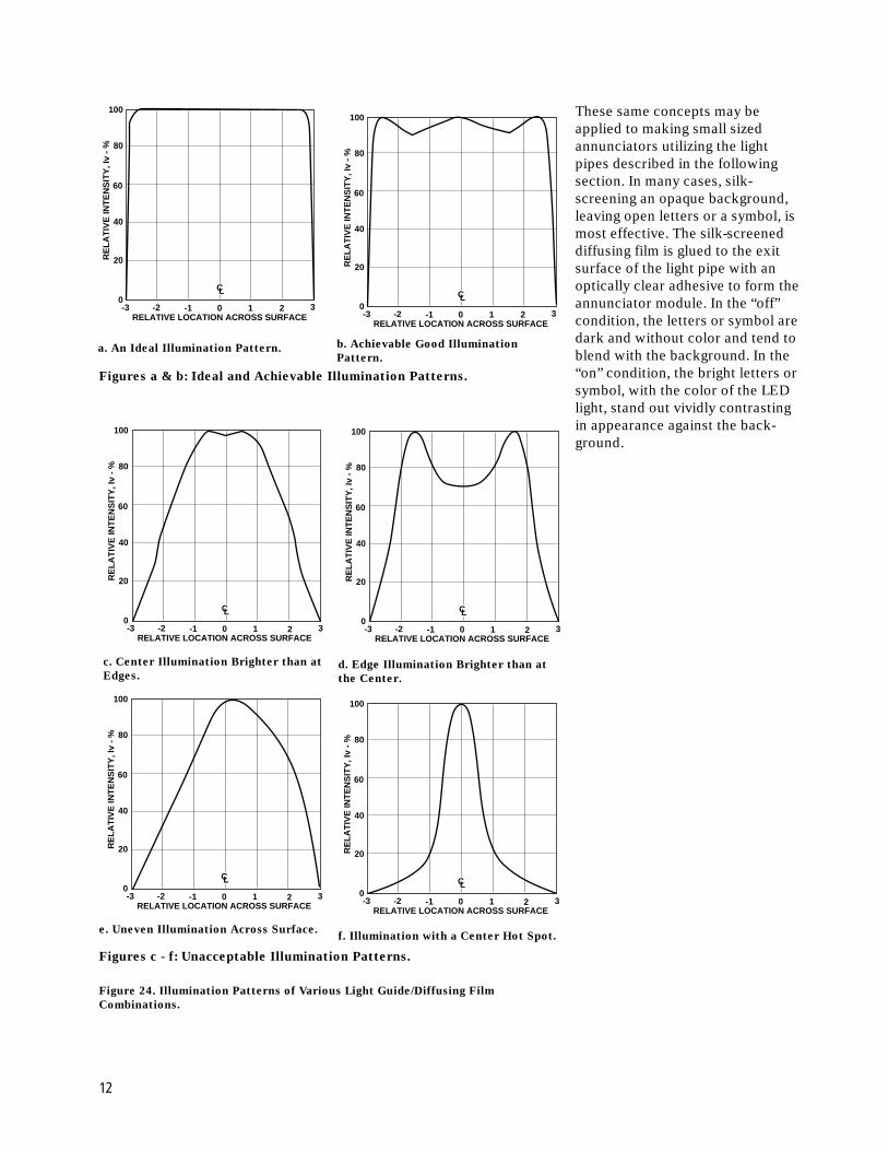
Illumination PatternsLuminous intensity variations, asmeasured across the exit surfaceof a light guide or a light guide/diffusing film combination, deter-mine the evenness of illumination.The ideal would be to have aperfect rectangularly shapedillumination pattern so that theluminous intensity is the same atall points across the surface, theedges, the corners, and the centerall be at the same luminance. Anapproximation to this ideal isshown in Figure 24a, where theillumination is flat across thesurface, falling off smoothly at theedges. However, in a good designthere are typically minor luminousintensity variations across thesurface as shown in Figure 24b.These variations should notexceed 20% of the luminousintensity at the center.
Figures 24c - 24f show variousluminous intensity patterns thatproduce unacceptable illuminationvariations across the face of anLCD display and should beavoided. Careful optical design ofthe light guide and selection of theproper diffusing film to reduceluminous intensity variationsshould produce an acceptableillumination pattern equivalent toFigure 24a or 24b.
Backlighting Flat Surface
Annunciator Panels Made with
a Diffusing Film
Flat plate light guides, wedge lightguides, and right angle and dualright angle wedge light guides, witheither SMT LED or standard T-1 3/4and T-1 LED lamps, are ideal forilluminating flat surface annuncia-tor panels. The techniques shownin Figures 18 through 24 directlyapply to annunciators that are thesame size as the LCD modules.Typically, annunciators are madeby silk-screening opaque lettersand symbols on the surface of adiffusing film, leaving open abackground area for illumination.The most effective approach is tosilk-screen the message on thebackside surface so it cannot bedamaged. The diffusing film isplaced directly onto the lightemitting surface of the light guideto form the annunciator unit. In the“off” condition, the backgroundsurrounding the message is darkand without color. When illumi-nated, the bright color of the LEDlight readily signifies to an ob-server the “on” condition of theannunciator. The opaque lettersand symbols forming the messageare easy to read against the illumi-nated background.
11
100
80
60
40
20
0-3 -2 -1 0 1 2 3
RELATIVE LOCATION ACROSS SURFACE
RE
LA
TIV
E IN
TE
NS
ITY
, Iv
- %
CL
a. An Ideal Illumination Pattern. b. Achievable Good Illumination
Pattern.
100
80
60
40
20
0-3 -2 -1 0 1 2 3
RELATIVE LOCATION ACROSS SURFACE
RE
LA
TIV
E IN
TE
NS
ITY
, Iv
- %
CL
100
80
60
40
20
0-3 -2 -1 0 1 2 3
RELATIVE LOCATION ACROSS SURFACE
RE
LA
TIV
E IN
TE
NS
ITY
, Iv
- %
CL
100
80
60
40
20
0-3 -2 -1 0 1 2 3
RELATIVE LOCATION ACROSS SURFACE
RE
LA
TIV
E IN
TE
NS
ITY
, Iv
- %
CL
100
80
60
40
20
0-3 -2 -1 0 1 2 3
RELATIVE LOCATION ACROSS SURFACE
RE
LA
TIV
E IN
TE
NS
ITY
, Iv
- %
CL
100
80
60
40
20
0-3 -2 -1 0 1 2 3
RELATIVE LOCATION ACROSS SURFACE
RE
LA
TIV
E IN
TE
NS
ITY
, Iv
- %
CL
These same concepts may beapplied to making small sizedannunciators utilizing the lightpipes described in the followingsection. In many cases, silk-screening an opaque background,leaving open letters or a symbol, ismost effective. The silk-screeneddiffusing film is glued to the exitsurface of the light pipe with anoptically clear adhesive to form theannunciator module. In the “off”condition, the letters or symbol aredark and without color and tend toblend with the background. In the“on” condition, the bright letters orsymbol, with the color of the LEDlight, stand out vividly contrastingin appearance against the back-ground.
Figures a & b: Ideal and Achievable Illumination Patterns.
c. Center Illumination Brighter than at
Edges.d. Edge Illumination Brighter than at
the Center.
e. Uneven Illumination Across Surface.f. Illumination with a Center Hot Spot.
Figures c - f: Unacceptable Illumination Patterns.
Figure 24. Illumination Patterns of Various Light Guide/Diffusing Film
Combinations.
12
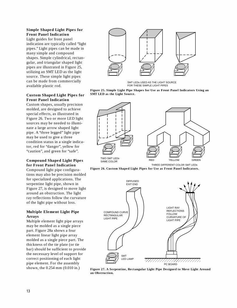
Figure 25. Simple Light Pipe Shapes for Use as Front Panel Indicators Using an
SMT LED as the Light Source.
���PC BOARD
SMTLED LAMP
LIGHT RAYREFLECTIONSFOLLOWCURVATURE OFLIGHT PIPE
COMPOUND CURVERECTANGULARLIGHT PIPE
DIFFUSEDEXIT END
Simple Shaped Light Pipes for
Front Panel Indication
Light guides for front panelindication are typically called “lightpipes.” Light pipes can be made inmany simple and compoundshapes. Simple cylindrical, rectan-gular, and triangular shaped lightpipes are illustrated in Figure 25,utilizing an SMT LED as the lightsource. These simple light pipescan be made from commerciallyavailable plastic rod.
Custom Shaped Light Pipes for
Front Panel Indication
Custom shapes, usually precisionmolded, are designed to achievespecial effects, as illustrated inFigure 26. Two or more LED lightsources may be needed to illumi-nate a large arrow shaped lightpipe. A “three legged” light pipemay be used to give a threecondition status in a single indica-tor, red for “danger”, yellow for“caution”, and green for “safe”.
Compound Shaped Light Pipes
for Front Panel Indication
Compound light pipe configura-tions may also be precision moldedfor specialized applications. Theserpentine light pipe, shown inFigure 27, is designed to move lightaround an obstruction. The lightray reflections follow the curvatureof the light pipe without loss.
Multiple Element Light Pipe
Arrays
Multiple element light pipe arraysmay be molded as a single piecepart. Figure 28a shows a fourelement linear light pipe arraymolded as a single piece part. Thethickness of the tie plate (or tiebar) should be sufficient to providethe necessary level of support forcorrect positioning of each lightpipe element. For the assemblyshown, the 0.254 mm (0.010 in.)
Figure 26. Custom Shaped Light Pipes for Use as Front Panel Indicators.
Figure 27. A Serpentine, Rectangular Light Pipe Designed to Move Light Around
an Obstruction.
SMT LEDs USED AS THE LIGHT SOURCEFOR THESE SIMPLE LIGHT PIPES
TWO SMT LEDsSAME COLOR RED YELLOW GREEN
THREE DIFFERENT COLOR SMT LEDs
13
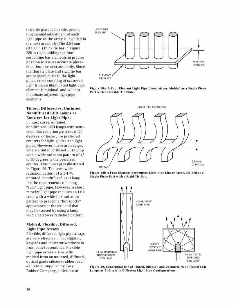
thick tie plate is flexible, permit-ting manual adjustment of eachlight pipe as the array is installed inthe next assembly. The 2.54 mm(0.100 in.) thick tie bar in Figure28b is rigid, holding the fourserpentine bar elements in preciseposition to assure accurate place-ment into the next assembly. Sincethe thin tie plate and rigid tie barare perpendicular to the lightpipes, cross coupling of scatteredlight from an illuminated light pipeelement is minimal, and will notilluminate adjacent light pipeelements.
Tinted, Diffused vs. Untinted,
Nondiffused LED Lamps as
Emitters for Light Pipes
In most cases, untinted,nondiffused LED lamps with semi-wide flux radiation patterns of 24degrees, or larger, are preferredemitters for light guides and lightpipes. However, there are designswhere a tinted, diffused LED lampwith a wide radiation pattern of 45to 60 degrees is the preferredemitter. This concept is illustratedin Figure 29. The semi-wideradiation pattern of a T-1 3/4untinted, nondiffused LED lampfits the requirements of a long“slim” light pipe. However, a short“stocky” light pipe requires an LEDlamp with a wide flux radiationpattern to prevent a “hot spotty”appearance at the exit end thatmay be caused by using a lampwith a narrower radiation pattern.
Molded, Flexible, Diffused,
Light Pipe Arrays
Flexible, diffused, light pipe arraysare very effective in backlightingkeypads and indicator windows infront panel assemblies. Flexiblelight pipe arrays are usuallymolded from an untinted, diffused,optical grade silicone rubber, suchas 150-OU, supplied by ToryRubber Company, a division of
LIGHT PIPEELEMENT
ELEMENTTIE PLATE
0.254 mm(0.010 IN.)
Figure 28a. A Four Element Light Pipe Linear Array, Molded as a Single Piece
Part with a Flexible Tie Plate.
Figure 28b A Four Element Serpentine Light Pipe Linear Array, Molded as a
Single Piece Part with a Rigid Tie Bar.
Figure 29. Conceptual Use of Tinted, Diffused and Untinted, Nondiffused LED
Lamps as Emitters in Different Light Pipe Configurations.
LIGHT PIPE ELEMENTS
TIE BAR
2.54 mm(0.100 IN.)
LONG, “SLIM”LIGHT PIPE
T-1 3/4 UNTINTEDNONDIFFUSED
LED LAMP
T-1 3/4 TINTEDDIFFUSEDLED LAMP
SHORT,“STOCKY”
LIGHT PIPE
14
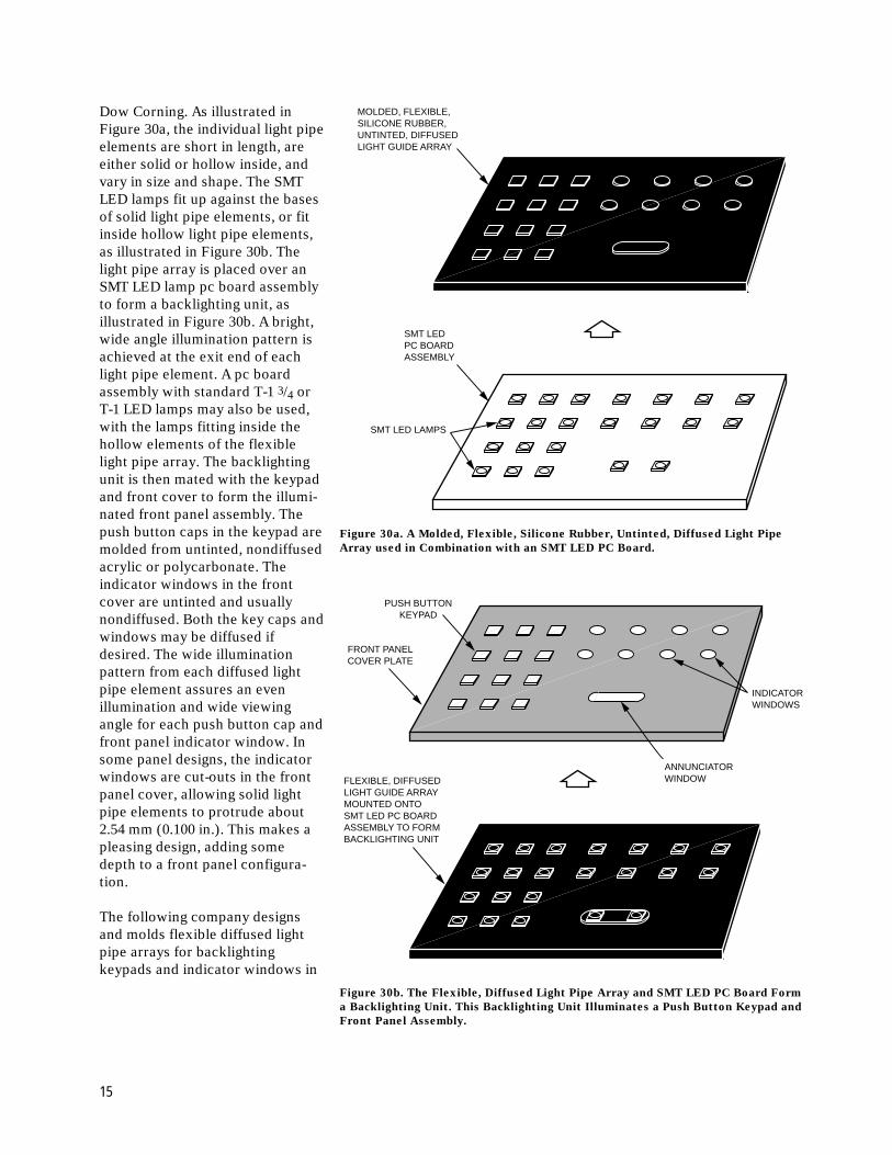
Dow Corning. As illustrated inFigure 30a, the individual light pipeelements are short in length, areeither solid or hollow inside, andvary in size and shape. The SMTLED lamps fit up against the basesof solid light pipe elements, or fitinside hollow light pipe elements,as illustrated in Figure 30b. Thelight pipe array is placed over anSMT LED lamp pc board assemblyto form a backlighting unit, asillustrated in Figure 30b. A bright,wide angle illumination pattern isachieved at the exit end of eachlight pipe element. A pc boardassembly with standard T-1 3/4 orT-1 LED lamps may also be used,with the lamps fitting inside thehollow elements of the flexiblelight pipe array. The backlightingunit is then mated with the keypadand front cover to form the illumi-nated front panel assembly. Thepush button caps in the keypad aremolded from untinted, nondiffusedacrylic or polycarbonate. Theindicator windows in the frontcover are untinted and usuallynondiffused. Both the key caps andwindows may be diffused ifdesired. The wide illuminationpattern from each diffused lightpipe element assures an evenillumination and wide viewingangle for each push button cap andfront panel indicator window. Insome panel designs, the indicatorwindows are cut-outs in the frontpanel cover, allowing solid lightpipe elements to protrude about2.54 mm (0.100 in.). This makes apleasing design, adding somedepth to a front panel configura-tion.
The following company designsand molds flexible diffused lightpipe arrays for backlightingkeypads and indicator windows in
FLEXIBLE, DIFFUSEDLIGHT GUIDE ARRAYMOUNTED ONTOSMT LED PC BOARDASSEMBLY TO FORMBACKLIGHTING UNIT
PUSH BUTTONKEYPAD
FRONT PANELCOVER PLATE
ANNUNCIATORWINDOW
INDICATORWINDOWS
Figure 30a. A Molded, Flexible, Silicone Rubber, Untinted, Diffused Light Pipe
Array used in Combination with an SMT LED PC Board.
Figure 30b. The Flexible, Diffused Light Pipe Array and SMT LED PC Board Form
a Backlighting Unit. This Backlighting Unit Illuminates a Push Button Keypad and
Front Panel Assembly.
SMT LEDPC BOARDASSEMBLY
SMT LED LAMPS
MOLDED, FLEXIBLE,SILICONE RUBBER,UNTINTED, DIFFUSEDLIGHT GUIDE ARRAY
15
front panel assemblies. Diffusedsilicone rubber 150-OU is thematerial used.
Keytek44 Old State Road #3New Milford, CT 06776(203) 350-1153FAX: (203) 350-1155
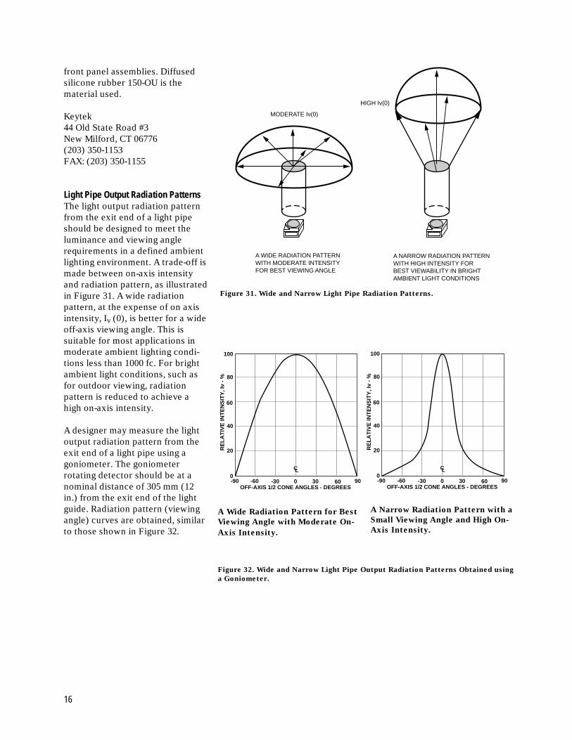
Light Pipe Output Radiation PatternsThe light output radiation patternfrom the exit end of a light pipeshould be designed to meet theluminance and viewing anglerequirements in a defined ambientlighting environment. A trade-off ismade between on-axis intensityand radiation pattern, as illustratedin Figure 31. A wide radiationpattern, at the expense of on axisintensity, Iv (0), is better for a wideoff-axis viewing angle. This issuitable for most applications inmoderate ambient lighting condi-tions less than 1000 fc. For brightambient light conditions, such asfor outdoor viewing, radiationpattern is reduced to achieve ahigh on-axis intensity.
A designer may measure the lightoutput radiation pattern from theexit end of a light pipe using agoniometer. The goniometerrotating detector should be at anominal distance of 305 mm (12in.) from the exit end of the lightguide. Radiation pattern (viewingangle) curves are obtained, similarto those shown in Figure 32.
Figure 31. Wide and Narrow Light Pipe Radiation Patterns.
HIGH Iv(0)
A NARROW RADIATION PATTERNWITH HIGH INTENSITY FORBEST VIEWABILITY IN BRIGHTAMBIENT LIGHT CONDITIONS
A WIDE RADIATION PATTERNWITH MODERATE INTENSITY FOR BEST VIEWING ANGLE
MODERATE Iv(0)
100
80
60
40
20
0-90 -60 -30 0 30 60 90
OFF-AXIS 1/2 CONE ANGLES - DEGREES
RE
LA
TIV
E IN
TE
NS
ITY
, Iv
- %
CL
100
80
60
40
20
0-90 -60 -30 0 30 60 90
OFF-AXIS 1/2 CONE ANGLES - DEGREES
RE
LA
TIV
E IN
TE
NS
ITY
, Iv
- %
CL
A Wide Radiation Pattern for Best
Viewing Angle with Moderate On-
Axis Intensity.
A Narrow Radiation Pattern with a
Small Viewing Angle and High On-
Axis Intensity.
Figure 32. Wide and Narrow Light Pipe Output Radiation Patterns Obtained using
a Goniometer.
16
Edge Lighting a Transparent
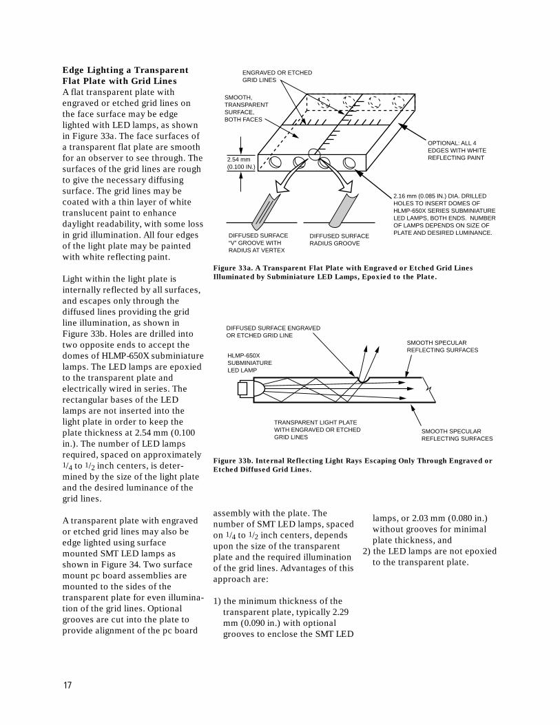
Flat Plate with Grid Lines
A flat transparent plate withengraved or etched grid lines onthe face surface may be edgelighted with LED lamps, as shownin Figure 33a. The face surfaces ofa transparent flat plate are smoothfor an observer to see through. Thesurfaces of the grid lines are roughto give the necessary diffusingsurface. The grid lines may becoated with a thin layer of whitetranslucent paint to enhancedaylight readability, with some lossin grid illumination. All four edgesof the light plate may be paintedwith white reflecting paint.
Light within the light plate isinternally reflected by all surfaces,and escapes only through thediffused lines providing the gridline illumination, as shown inFigure 33b. Holes are drilled intotwo opposite ends to accept thedomes of HLMP-650X subminiaturelamps. The LED lamps are epoxiedto the transparent plate andelectrically wired in series. Therectangular bases of the LEDlamps are not inserted into thelight plate in order to keep theplate thickness at 2.54 mm (0.100in.). The number of LED lampsrequired, spaced on approximately1/4 to 1/2 inch centers, is deter-mined by the size of the light plateand the desired luminance of thegrid lines.
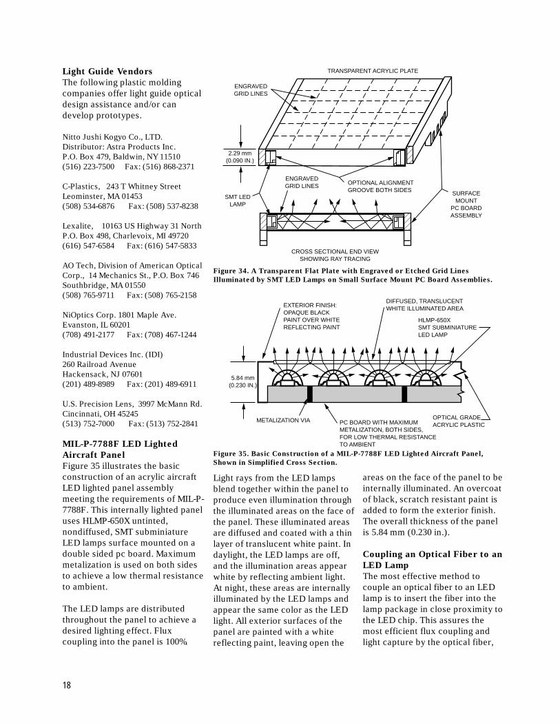
A transparent plate with engravedor etched grid lines may also beedge lighted using surfacemounted SMT LED lamps asshown in Figure 34. Two surfacemount pc board assemblies aremounted to the sides of thetransparent plate for even illumina-tion of the grid lines. Optionalgrooves are cut into the plate toprovide alignment of the pc board
Figure 33a. A Transparent Flat Plate with Engraved or Etched Grid Lines
Illuminated by Subminiature LED Lamps, Epoxied to the Plate.
Figure 33b. Internal Reflecting Light Rays Escaping Only Through Engraved or
Etched Diffused Grid Lines.
HLMP-650XSUBMINIATURELED LAMP
DIFFUSED SURFACE ENGRAVEDOR ETCHED GRID LINE
SMOOTH SPECULARREFLECTING SURFACES
SMOOTH SPECULARREFLECTING SURFACES
TRANSPARENT LIGHT PLATEWITH ENGRAVED OR ETCHEDGRID LINES
assembly with the plate. Thenumber of SMT LED lamps, spacedon 1/4 to 1/2 inch centers, dependsupon the size of the transparentplate and the required illuminationof the grid lines. Advantages of thisapproach are:
1) the minimum thickness of thetransparent plate, typically 2.29mm (0.090 in.) with optionalgrooves to enclose the SMT LED
lamps, or 2.03 mm (0.080 in.)without grooves for minimalplate thickness, and
2) the LED lamps are not epoxiedto the transparent plate.
SMOOTH,TRANSPARENTSURFACE,BOTH FACES
2.16 mm (0.085 IN.) DIA. DRILLEDHOLES TO INSERT DOMES OFHLMP-650X SERIES SUBMINIATURELED LAMPS, BOTH ENDS. NUMBER OF LAMPS DEPENDS ON SIZE OFPLATE AND DESIRED LUMINANCE.
2.54 mm(0.100 IN.)
ENGRAVED OR ETCHEDGRID LINES
OPTIONAL: ALL 4EDGES WITH WHITEREFLECTING PAINT
DIFFUSED SURFACE“V” GROOVE WITHRADIUS AT VERTEX
DIFFUSED SURFACERADIUS GROOVE
17
Light Guide Vendors
The following plastic moldingcompanies offer light guide opticaldesign assistance and/or candevelop prototypes.
Nitto Jushi Kogyo Co., LTD.Distributor: Astra Products Inc.P.O. Box 479, Baldwin, NY 11510(516) 223-7500 Fax: (516) 868-2371
C-Plastics, 243 T Whitney StreetLeominster, MA 01453(508) 534-6876 Fax: (508) 537-8238
Lexalite, 10163 US Highway 31 NorthP.O. Box 498, Charlevoix, MI 49720(616) 547-6584 Fax: (616) 547-5833
AO Tech, Division of American OpticalCorp., 14 Mechanics St., P.O. Box 746Southbridge, MA 01550(508) 765-9711 Fax: (508) 765-2158
NiOptics Corp. 1801 Maple Ave.Evanston, IL 60201(708) 491-2177 Fax: (708) 467-1244
Industrial Devices Inc. (IDI)260 Railroad AvenueHackensack, NJ 07601(201) 489-8989 Fax: (201) 489-6911
U.S. Precision Lens, 3997 McMann Rd.Cincinnati, OH 45245(513) 752-7000 Fax: (513) 752-2841
MIL-P-7788F LED Lighted
Aircraft Panel
Figure 35 illustrates the basicconstruction of an acrylic aircraftLED lighted panel assemblymeeting the requirements of MIL-P-7788F. This internally lighted paneluses HLMP-650X untinted,nondiffused, SMT subminiatureLED lamps surface mounted on adouble sided pc board. Maximummetalization is used on both sidesto achieve a low thermal resistanceto ambient.
The LED lamps are distributedthroughout the panel to achieve adesired lighting effect. Fluxcoupling into the panel is 100%.
Figure 34. A Transparent Flat Plate with Engraved or Etched Grid Lines
Illuminated by SMT LED Lamps on Small Surface Mount PC Board Assemblies.
Light rays from the LED lampsblend together within the panel toproduce even illumination throughthe illuminated areas on the face ofthe panel. These illuminated areasare diffused and coated with a thinlayer of translucent white paint. Indaylight, the LED lamps are off,and the illumination areas appearwhite by reflecting ambient light.At night, these areas are internallyilluminated by the LED lamps andappear the same color as the LEDlight. All exterior surfaces of thepanel are painted with a whitereflecting paint, leaving open the
areas on the face of the panel to beinternally illuminated. An overcoatof black, scratch resistant paint isadded to form the exterior finish.The overall thickness of the panelis 5.84 mm (0.230 in.).
Coupling an Optical Fiber to an
LED Lamp
The most effective method tocouple an optical fiber to an LEDlamp is to insert the fiber into thelamp package in close proximity tothe LED chip. This assures themost efficient flux coupling andlight capture by the optical fiber,
Figure 35. Basic Construction of a MIL-P-7788F LED Lighted Aircraft Panel,
Shown in Simplified Cross Section.
��
���
��
TRANSPARENT ACRYLIC PLATE
SURFACEMOUNT
PC BOARDASSEMBLY
OPTIONAL ALIGNMENTGROOVE BOTH SIDES
2.29 mm(0.090 IN.)
SMT LEDLAMP
ENGRAVEDGRID LINES
ENGRAVEDGRID LINES
CROSS SECTIONAL END VIEWSHOWING RAY TRACING
5.84 mm(0.230 IN.)
METALIZATION VIA PC BOARD WITH MAXIMUMMETALIZATION, BOTH SIDES,FOR LOW THERMAL RESISTANCETO AMBIENT
OPTICAL GRADEACRYLIC PLASTIC
HLMP-650XSMT SUBMINIATURELED LAMP
DIFFUSED, TRANSLUCENTWHITE ILLUMINATED AREAEXTERIOR FINISH:
OPAQUE BLACKPAINT OVER WHITEREFLECTING PAINT
18
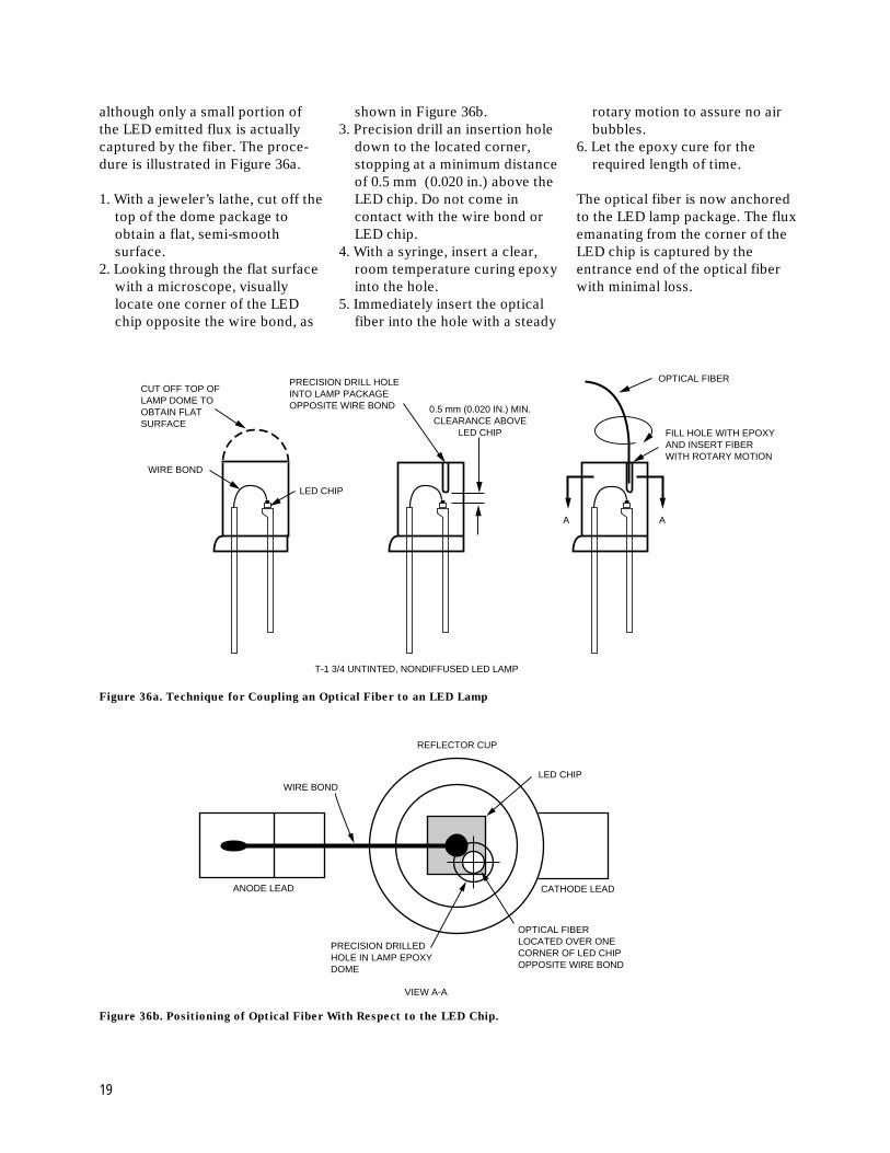
although only a small portion ofthe LED emitted flux is actuallycaptured by the fiber. The proce-dure is illustrated in Figure 36a.
1. With a jeweler’s lathe, cut off thetop of the dome package toobtain a flat, semi-smoothsurface.
2. Looking through the flat surfacewith a microscope, visuallylocate one corner of the LEDchip opposite the wire bond, as
shown in Figure 36b.3. Precision drill an insertion hole
down to the located corner,stopping at a minimum distanceof 0.5 mm (0.020 in.) above theLED chip. Do not come incontact with the wire bond orLED chip.
4. With a syringe, insert a clear,room temperature curing epoxyinto the hole.
5. Immediately insert the opticalfiber into the hole with a steady
rotary motion to assure no airbubbles.
6. Let the epoxy cure for therequired length of time.
The optical fiber is now anchoredto the LED lamp package. The fluxemanating from the corner of theLED chip is captured by theentrance end of the optical fiberwith minimal loss.
Figure 36a. Technique for Coupling an Optical Fiber to an LED Lamp
LED CHIP
WIRE BOND
CUT OFF TOP OFLAMP DOME TOOBTAIN FLATSURFACE
PRECISION DRILL HOLEINTO LAMP PACKAGEOPPOSITE WIRE BOND
OPTICAL FIBER
FILL HOLE WITH EPOXYAND INSERT FIBERWITH ROTARY MOTION
0.5 mm (0.020 IN.) MIN.CLEARANCE ABOVE
LED CHIP
A A
T-1 3/4 UNTINTED, NONDIFFUSED LED LAMP
WIRE BONDLED CHIP
REFLECTOR CUP
CATHODE LEAD
OPTICAL FIBERLOCATED OVER ONECORNER OF LED CHIPOPPOSITE WIRE BOND
PRECISION DRILLEDHOLE IN LAMP EPOXYDOME
ANODE LEAD
VIEW A-A
Figure 36b. Positioning of Optical Fiber With Respect to the LED Chip.
19

T-1 LED Lamps
Part Number LED and Color Viewing Angle Iv (20 mA) mcd
HLMP-K105 AS AlGaAs - 637 nm Red 45° 65
HLMA-KL00 AS AlInGaP -592 nm Amber 45° 200
HLMA-KH00 AS AlInGaP - 615 nm Red-Orange 45° 200
HLMP-1340 GaP - 626 nm High Efficiency Red 60° 55
HLMP-1440 GaP - 585 nm Yellow 60° 45
HLMP-1540 GaP - 570 nm Green 60° 45
20
T-1 3/4 LED Lamps
Part Number LED and Color Viewing Angle Iv, mcd (at 20 mA)
Min. Typ.
HLMP-3750 GaP - 626 nm High Efficiency Red 24° 90 125
HLMP-3850 GaP - 585 nm Yellow 24° 96 140
HLMP-3950 GaP - 570 nm Green 24° 111 265
HLMP-C025-P0000 AS AlInGaP - 625 nm Red 25° 500 1000
HLMP-C225-O0000 AS AlInGaP - 590 nm Amber 25° 450 800
HLMP-C625-P0000 AS AlInGaP - 637 nm Deep Red 25° 500 700
HLMP-DB25-P0000 GaN - 462 nm Blue 25° 40 100
HLMP-DM25-M0000 InGaN - 527 nm Green 25° 245 970
HLMP-DS25-R0000 InGaN - 470 nm Blue 25° 100 260
HLMP-EL24-PS000 AS AlInGaP - 590 nm Amber 23° 765 ––
HLMP-EG24-PS000 AS AlInGaP - 626 nm Red 23° 765 ––
HLMP-EL25-SV000 TS AlInGaP - 592 nm Amber 23° 1650 ––
HLMP-ED25-TW000 TS AlInGaP - 630 nm Red 23° 2170 ––
HLMP-EL30-MQ000 AS AlInGaP - 590 nm Amber 30° 450 ––
HLMP-EG30-NR000 AS AlInGaP - 626 nm Red 30° 590 ––
HLMP-EL31-SV000 TS AlInGaP - 592 nm Amber 30° 1650 ––
HLMP-ED31-SV000 TS AlInGaP - 630 nm Red 30° 1650 ––
HLMP-CB15-P0000 InGaN - 472 nm Blue 15° 765 ––
HLMP-CM15-S0000 InGaN - 525 nm Green 15° 1650 ––
HLMP-CB30-K0000 InGaN - 472 nm Blue 30° 270 ––
HLMP-CM30-M0000 InGaN - 525 nm Green 30° 450 ––
HLMP-EL24-SV000 AS AlInGaP - 590 nm Amber 23° 1650 ––
HLMP-EL30-SV000 AS AlInGaP - 590 nm Amber 30° 1650 ––
List of LED Lamps, Untinted, Nondiffused, Recommended for use in Light Guide Applications

Please request Agilent Technologies’ Surface Mount LED Selection Guide for full SMT LED offering.
SMT Subminiature LED Lamps
Part Number LED and Color Viewing Angle Iv (20 mA) mcd
HLMP-Q105 AS AlGaAs - 639 nm Red 28° 200
HLMA-QL00 AS AlInGaP -592 nm Amber 15° 500
HLMA-QH00 AS AlInGaP - 615 nm Red-Orange 15° 500
HLMP-6305 GaP - 626 nm High Efficiency Red 28° 40
HLMP-6405 GaP - 585 nm Yellow 28° 20
HLMP-6505 GaP - 570 nm Green 28° 40
SMT LED Lamps
Part Number LED and Color Viewing Angle Iv (20 mA) mcd
HSMH-A100 AS AlGaAs - 637 nm Red 120° 50
HSMS-A100 GaP - 626 nm High Efficiency Red 120° 15
HSMD-A100 GaP - 602 nm High Orange 120° 15
HSMY-A100 GaP - 585 nm Yellow 120° 15
HSMG-A100 GaP - 570 nm Green 120° 15
HSMH-C191 AS AlGaAs - 637 nm Red 170° 17
HSMS-C191 GaP - 626 nm High Efficiency Red 170° 10
HSMD-C191 GaP - 602 nm High Orange 170° 8
HSMY-C191 GaP - 585 nm Yellow 170° 8
HSMG-C191 GaP - 570 nm Green 170° 15
21
www.agilent.com/semiconductorsFor product information and a complete list ofdistributors, please go to our web site.
For technical assistance call:
Americas/Canada: +1 (800) 235-0312 or(408) 654-8675
Europe: +49 (0) 6441 92460
China: 10800 650 0017
Hong Kong: (+65) 271 2451
India, Australia, New Zealand: (+65) 271 2394
Japan: (+81 3) 3335-8152(Domestic/International), or0120-61-1280(Domestic Only)
Korea: (+65) 271 2194
Malaysia, Singapore: (+65) 271 2054
Taiwan: (+65) 271 2654
Data subject to change.Copyright © 2001 Agilent Technologies, Inc.Obsoletes 5965-7399EDecember 7, 20015988-5086EN