Embed Size (px)
Citation preview
Lighting fundamentals
About light and photometrics
• Generation of light
• Human vision
• Black body
• Colour
• Basic principles of lighting
• Light sources
Light
Vision
Colour
What is light?
• Light is electromagnetic radiation
and
• The human eye is sensible to this radiation
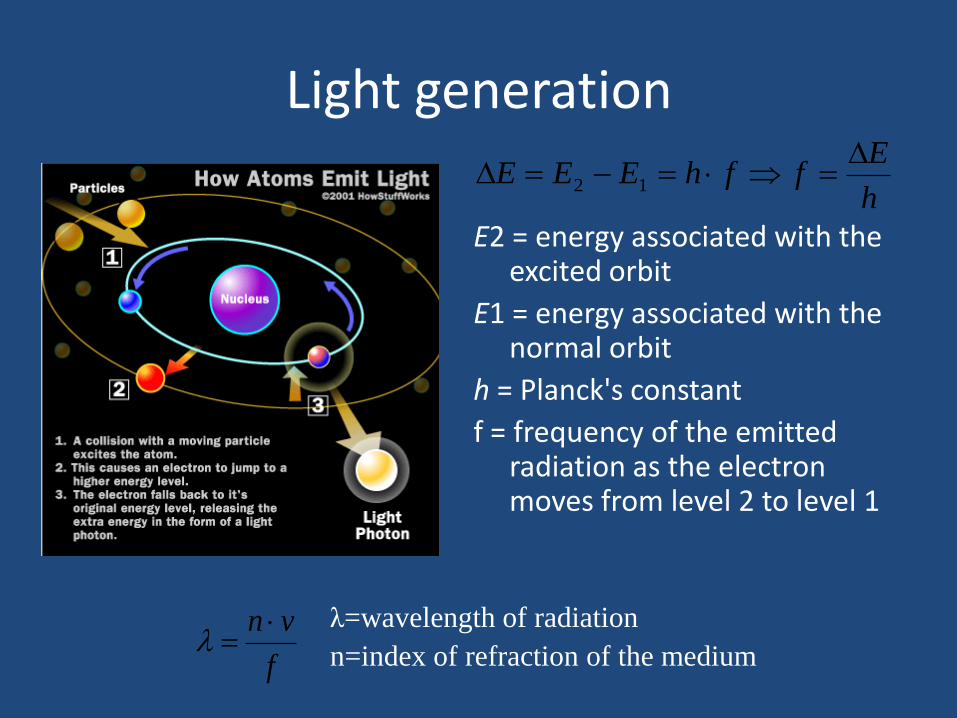
Light generation
E2 = energy associated with the excited orbit
E1 = energy associated with the normal orbit
h = Planck's constant
f = frequency of the emitted radiation as the electron moves from level 2 to level 1
h
EffhEEE
12
f
vn
λ=wavelength of radiation
n=index of refraction of the medium
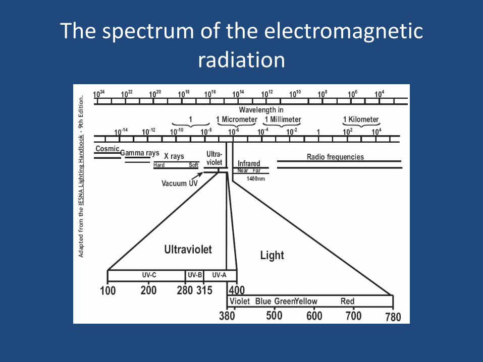
The spectrum of the electromagnetic radiation
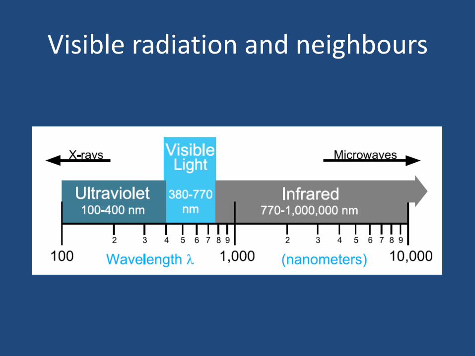
Visible radiation and neighbours
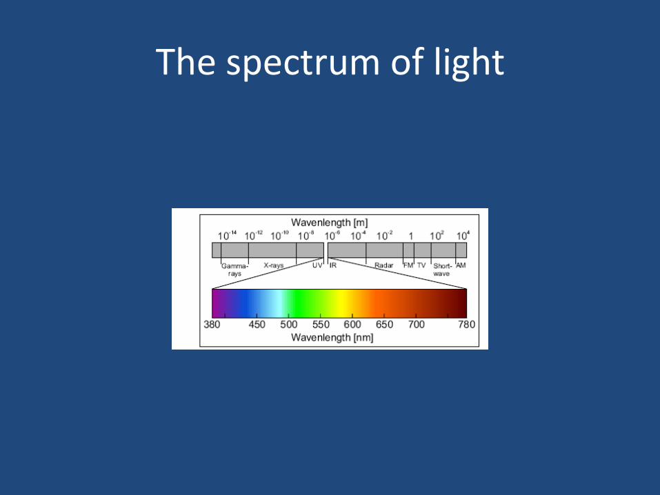
The spectrum of light
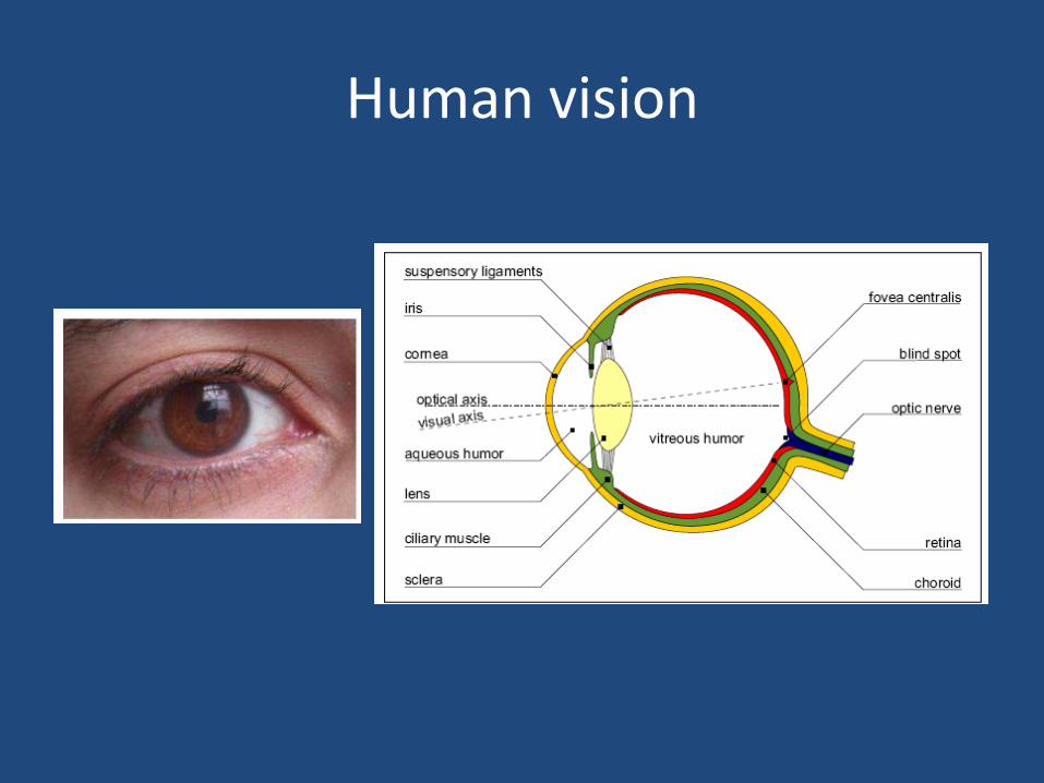
Human vision
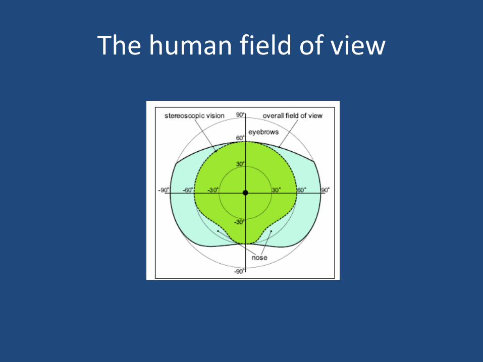
The human field of view
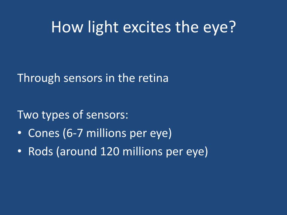
How light excites the eye?
Through sensors in the retina
Two types of sensors:
• Cones (6-7 millions per eye)
• Rods (around 120 millions per eye)
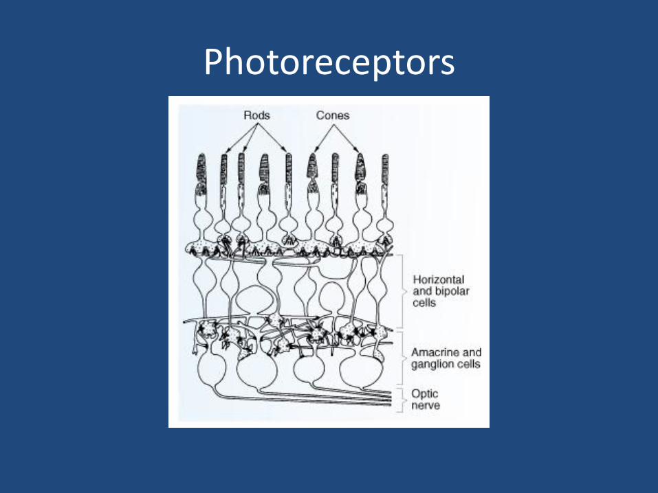
Photoreceptors
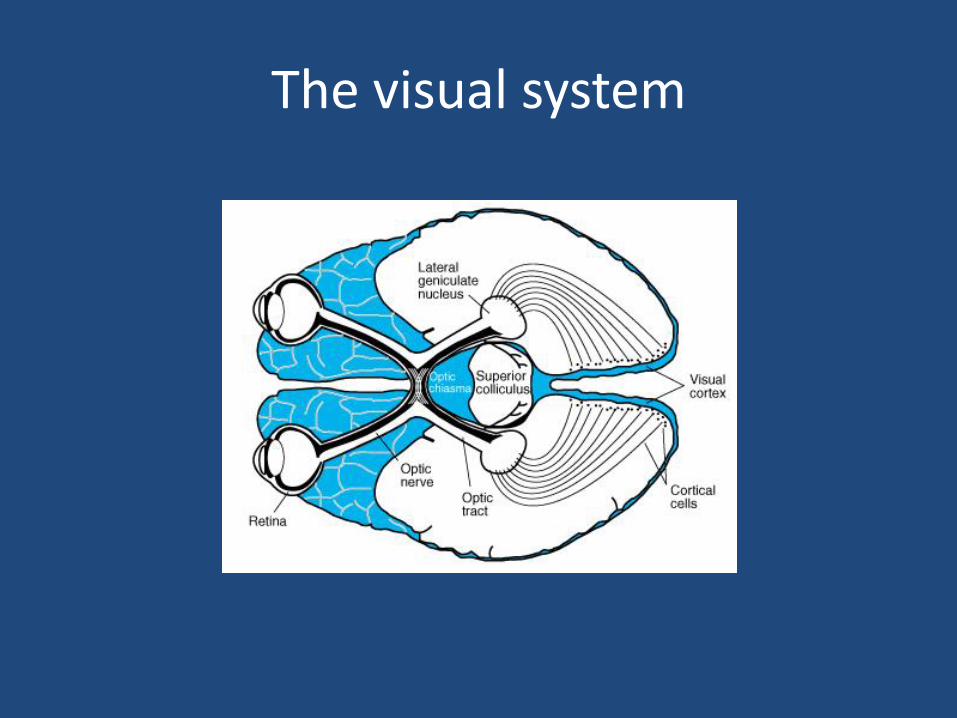
The visual system
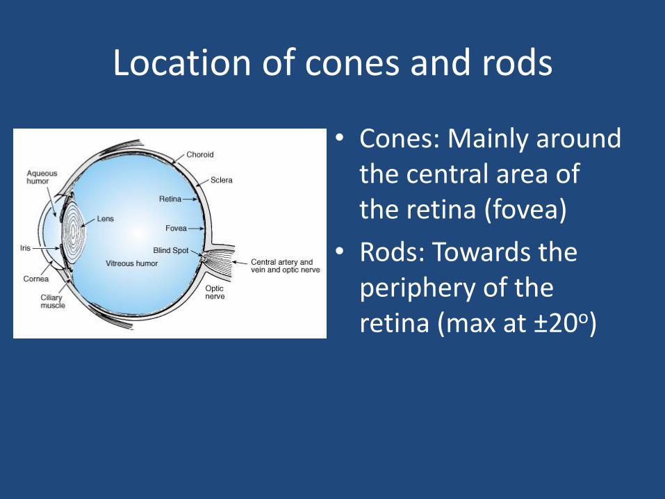
Location of cones and rods
• Cones: Mainly around the central area of the retina (fovea)
• Rods: Towards the periphery of the retina (max at ±20o)
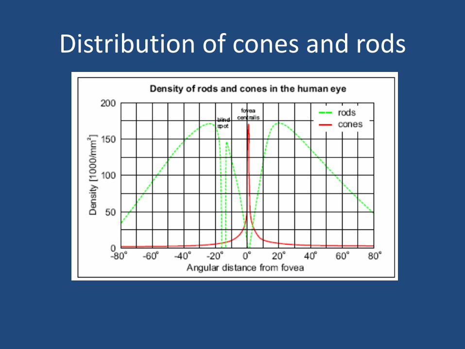
Distribution of cones and rods

Cones
• Axial vision (±5o=10o visual field)
• Less sensitive than rods
• Their sensitivity decreases at low light levels
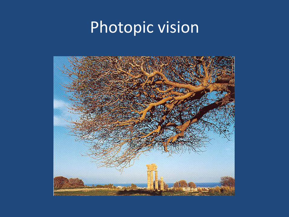
• Photopic vision (daylight, illuminated areas)
• Responsible for colour recognition
• Highest sensitivity at 555 nm
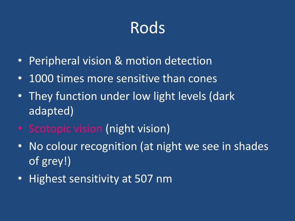
Rods
• Peripheral vision & motion detection
• 1000 times more sensitive than cones
• They function under low light levels (dark adapted)
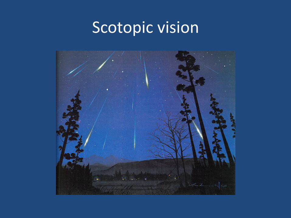
• Scotopic vision (night vision)
• No colour recognition (at night we see in shades of grey!)
• Highest sensitivity at 507 nm
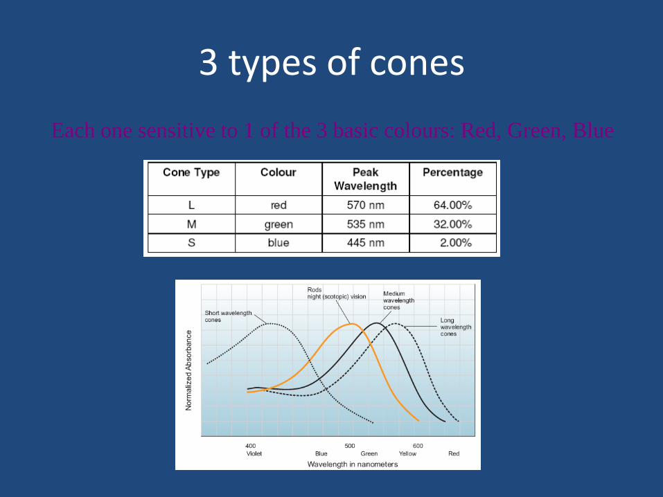
3 types of cones
Each one sensitive to 1 of the 3 basic colours: Red, Green, Blue
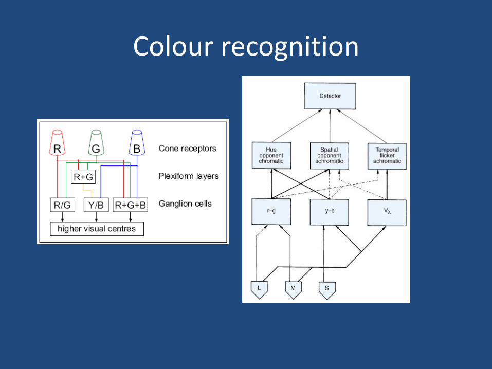
Colour recognition
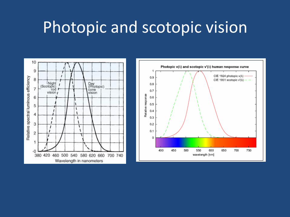
Photopic and scotopic vision
Photopic vision
Scotopic vision
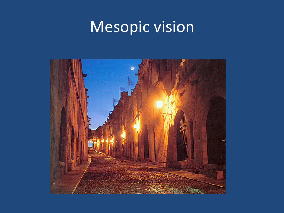
Mesopic vision
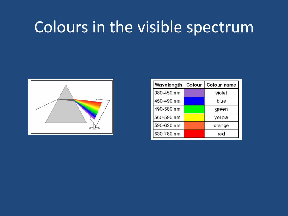
Colours in the visible spectrum
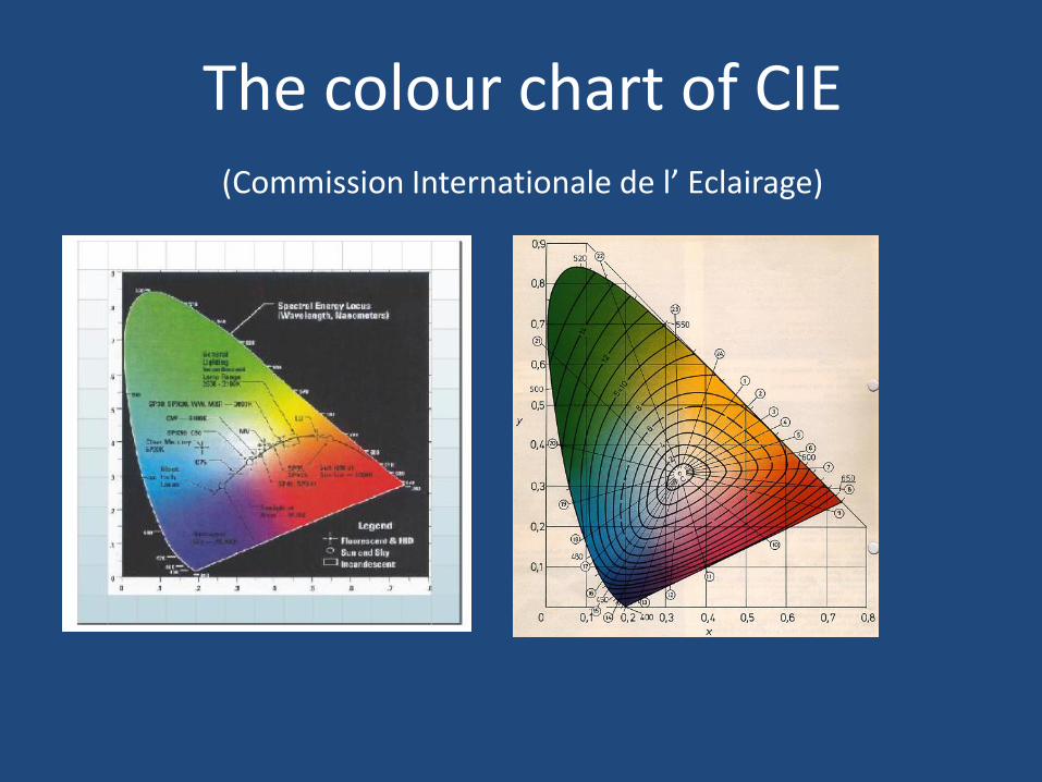
The colour chart of CIE (Commission Internationale de l’ Eclairage)
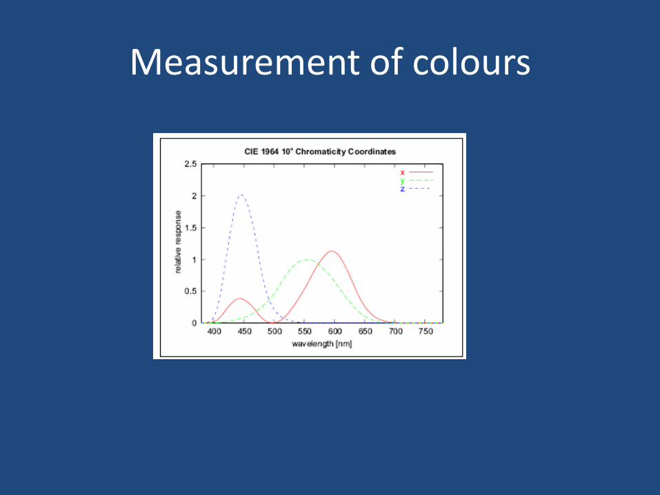
Measurement of colours
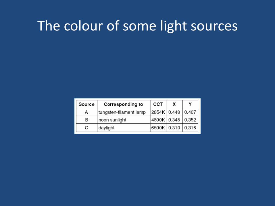
The colour of some light sources
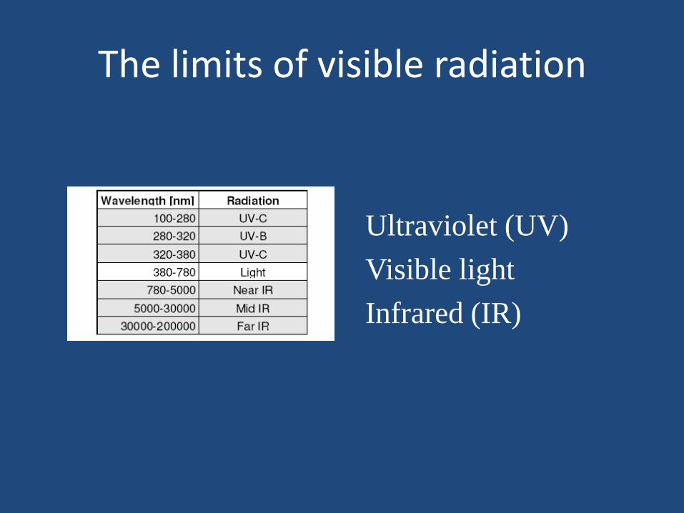
The limits of visible radiation
Ultraviolet (UV)
Visible light
Infrared (IR)
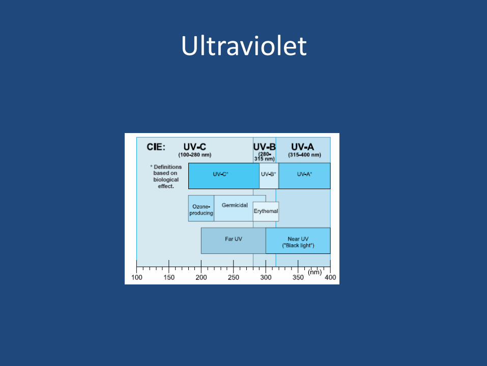
Ultraviolet
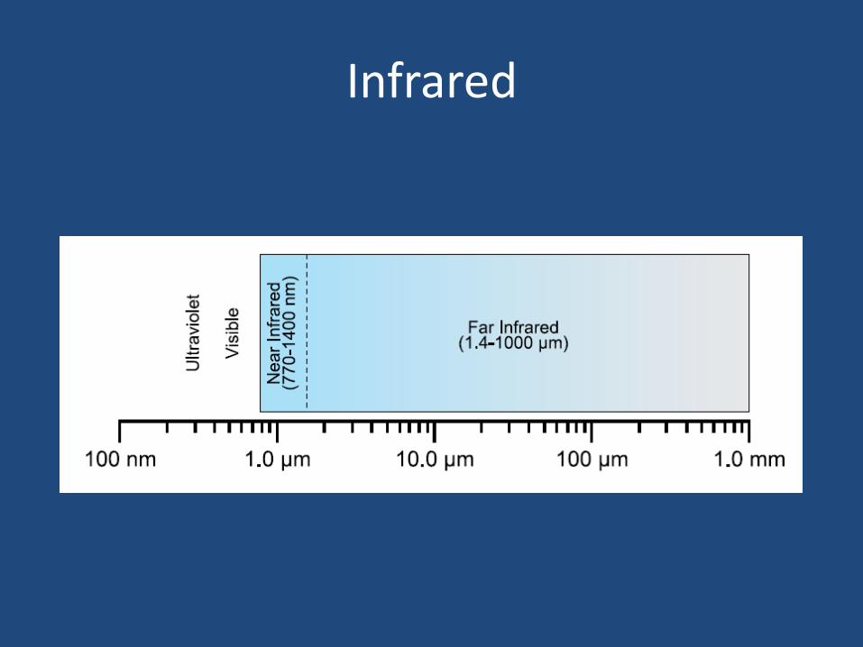
Infrared
Colour of light sources
• How do we measure the colour of light sources?
– Comparing the colour of the light of the source with the colour of the radiation of a “black body” (Planckian radiator, black body of Max Planck)
The black body
– Theoretical
– Definitely not only black in colour
– A black painted body absorbs only the visible light (but not UV, IR, X-rays etc)
– The black body (Planckian radiator) absorbs ALL radiations
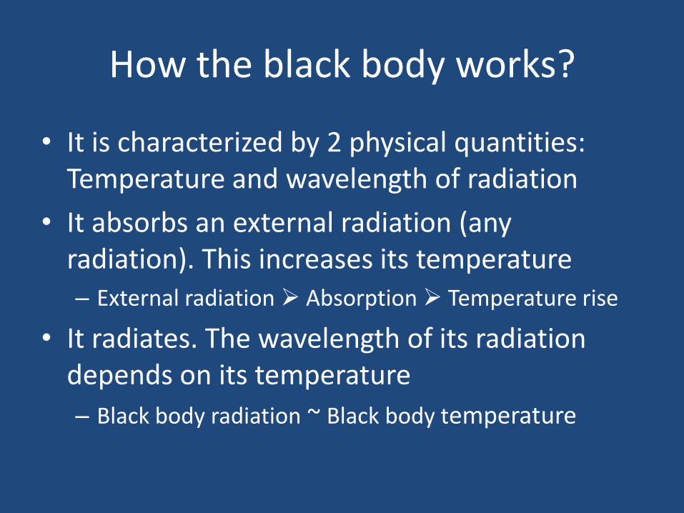
How the black body works?
• It is characterized by 2 physical quantities: Temperature and wavelength of radiation
• It absorbs an external radiation (any radiation). This increases its temperature – External radiation Absorption Temperature rise
• It radiates. The wavelength of its radiation depends on its temperature
– Black body radiation ~ Black body temperature
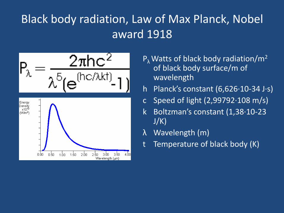
Black body radiation, Law of Max Planck, Nobel award 1918
Pλ Watts of black body radiation/m2 of black body surface/m of wavelength
h Planck’s constant (6,626·10-34 J·s)
c Speed of light (2,99792·108 m/s)
k Boltzman’s constant (1,38·10-23 J/K)
λ Wavelength (m)
t Temperature of black body (Κ)
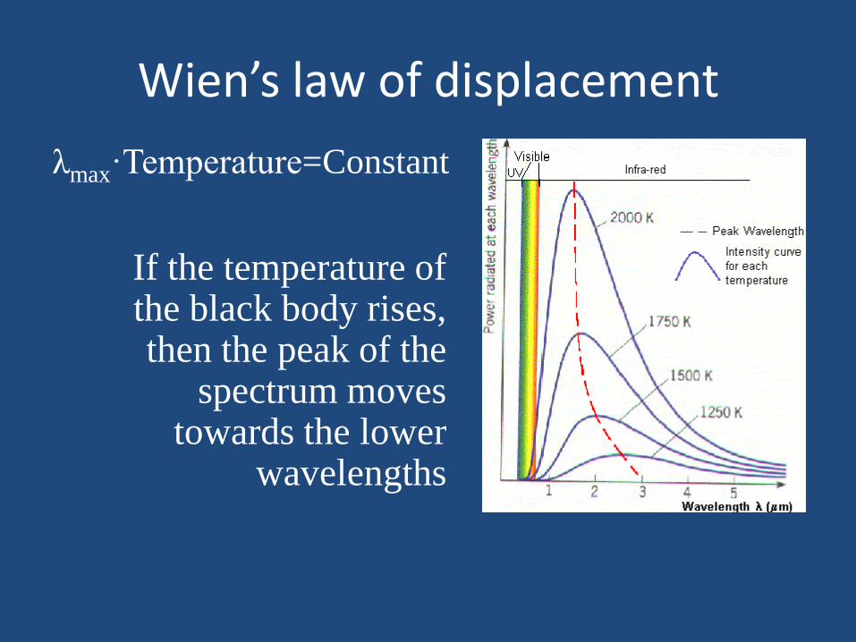
Wien’s law of displacement
λmax·Temperature=Constant
If the temperature of the black body rises, then the peak of the
spectrum moves towards the lower
wavelengths
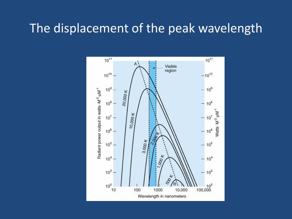
The displacement of the peak wavelength
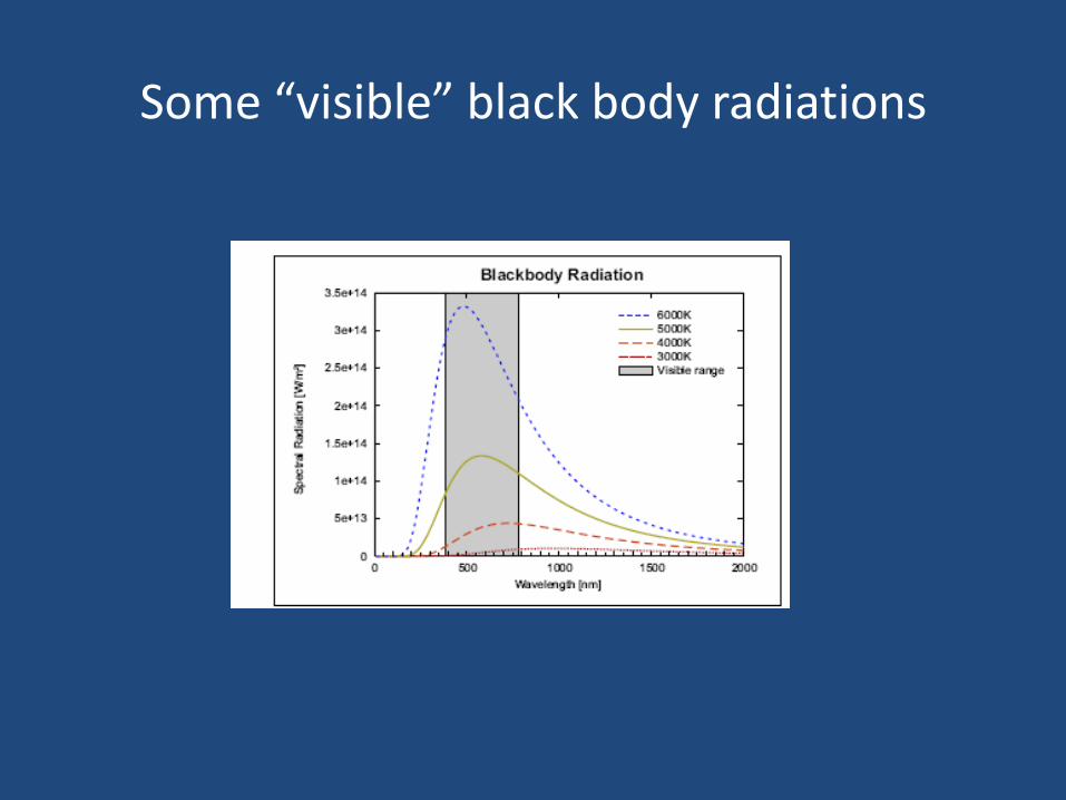
Some “visible” black body radiations
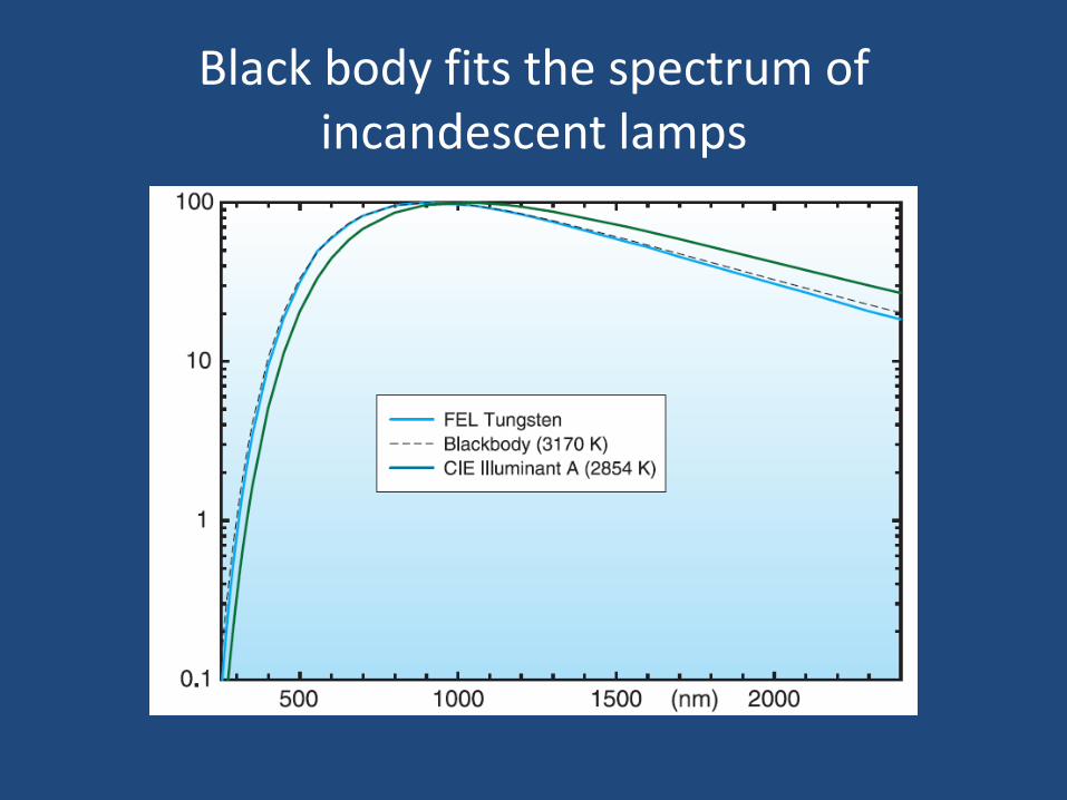
Black body fits the spectrum of incandescent lamps
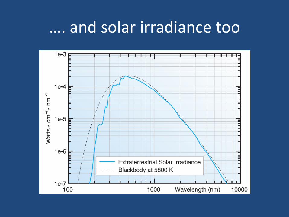
…. and solar irradiance too
Photometry Lab
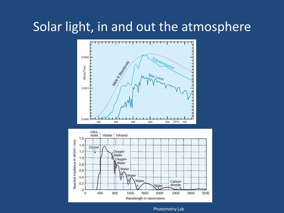
Solar light, in and out the atmosphere
Colour temperature
• Colour temperature is a measure for describing the colour of light sources
• It indicates the equivalent temperature that a black body would need to have in order to produce light of the same colour
• Thus, we express the colour of a light source with the temperature (in Kelvins) of the respective black body
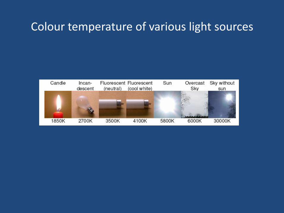
Colour temperature of various light sources
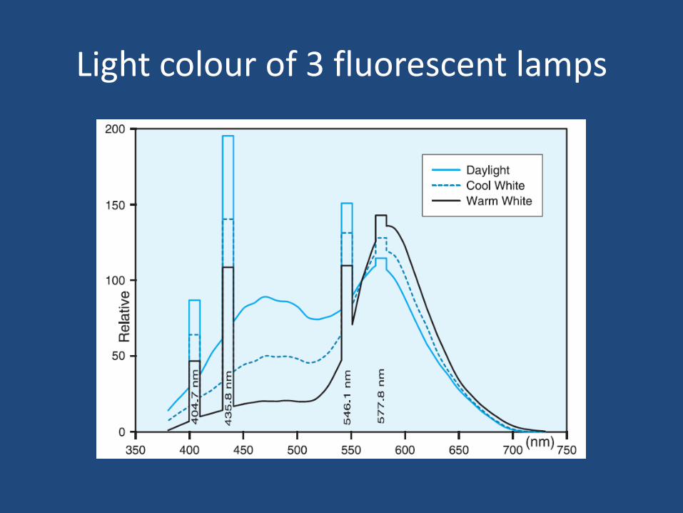
Light colour of 3 fluorescent lamps
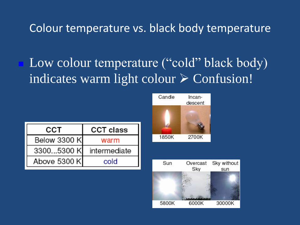
Colour temperature vs. black body temperature
Low colour temperature (“cold” black body)
indicates warm light colour Confusion!
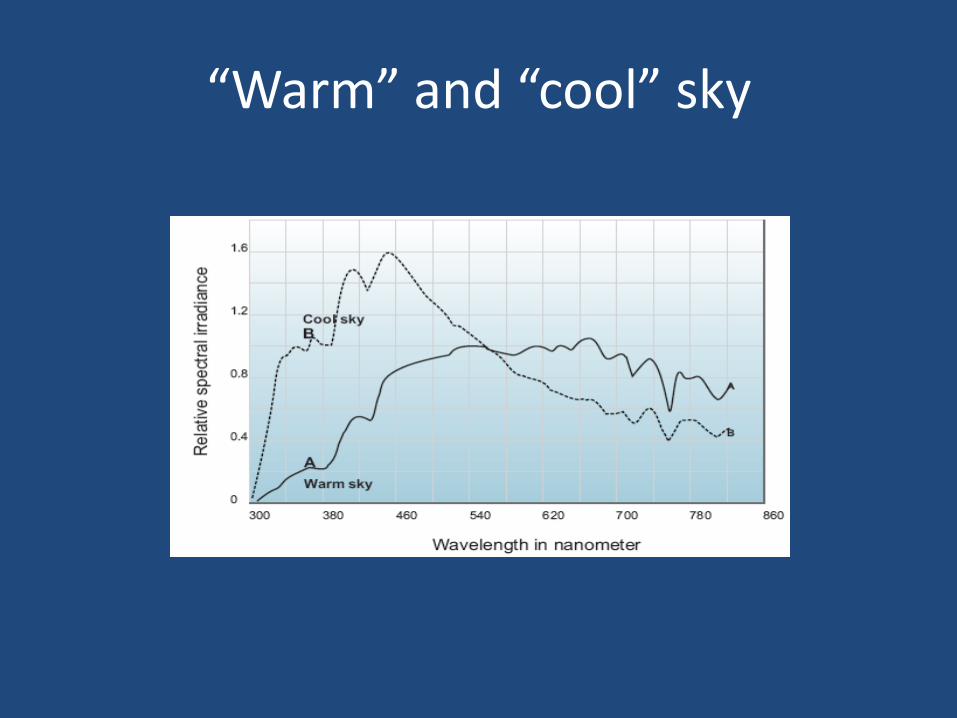
“Warm” and “cool” sky
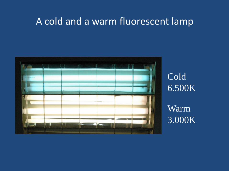
A cold and a warm fluorescent lamp
Cold
6.500K
Warm
3.000K
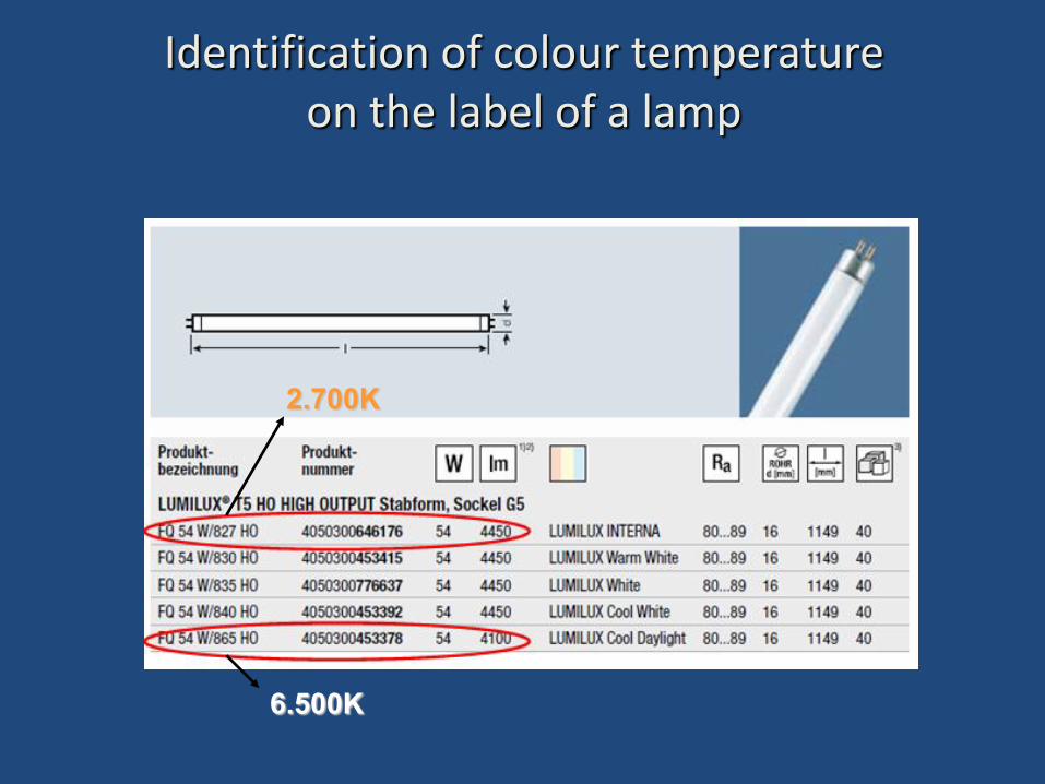
6.500Κ
2.700Κ
Identification of colour temperature on the label of a lamp
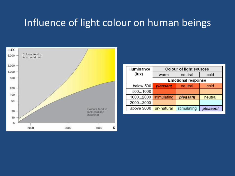
Influence of light colour on human beings
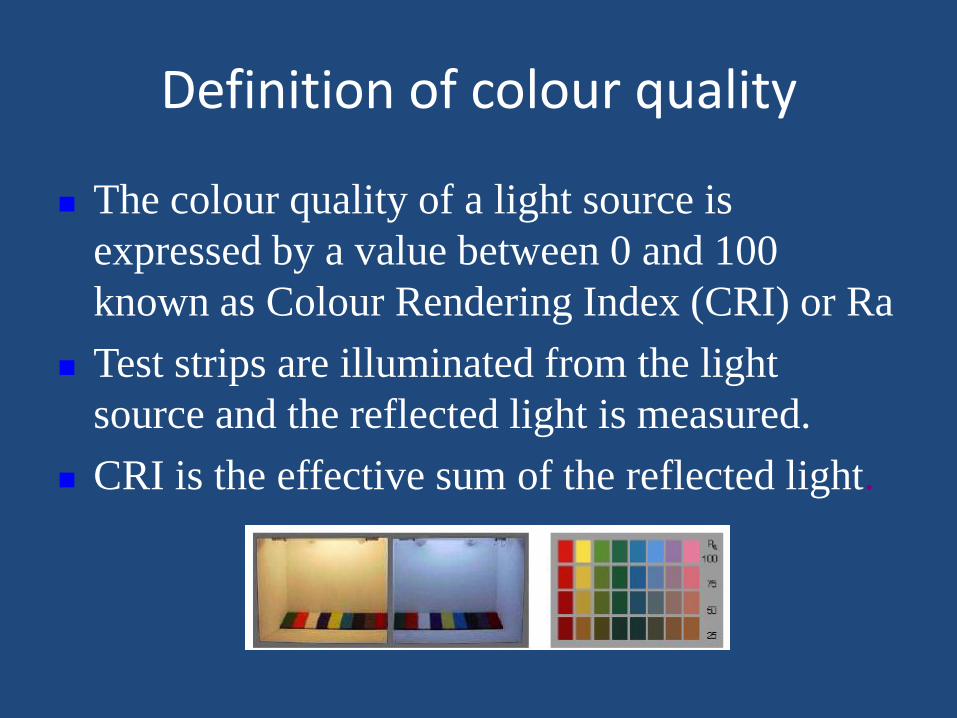
Definition of colour quality
The colour quality of a light source is
expressed by a value between 0 and 100
known as Colour Rendering Index (CRI) or Ra
Test strips are illuminated from the light
source and the reflected light is measured.
CRI is the effective sum of the reflected light.
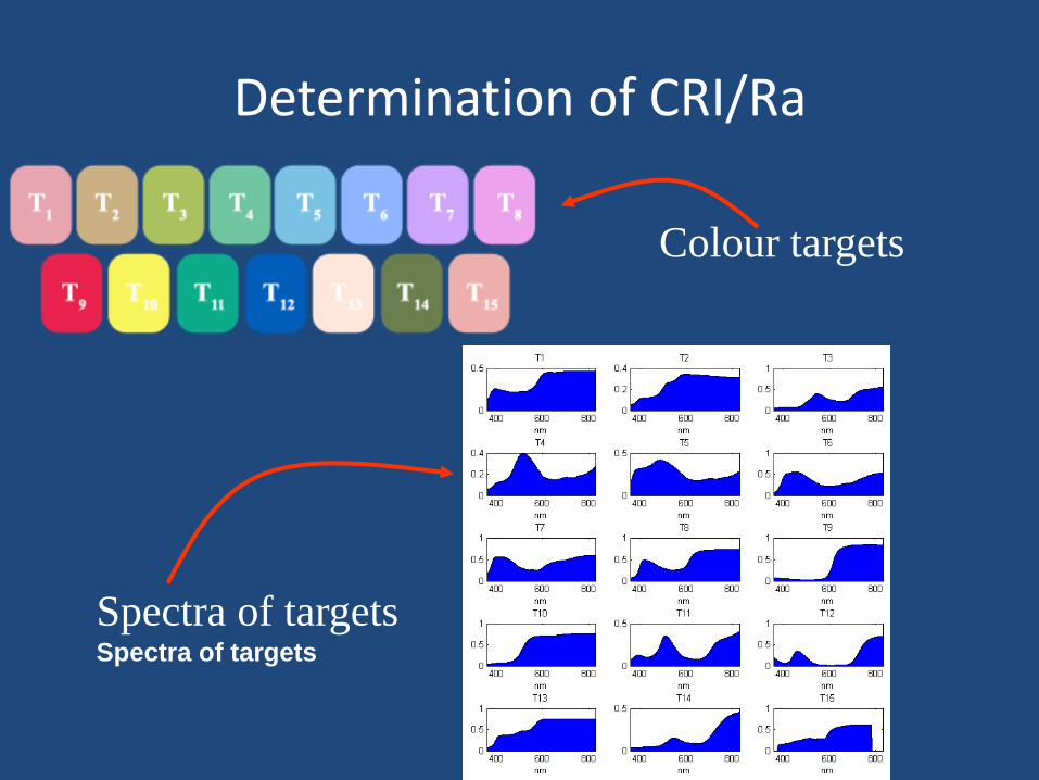
Determination of CRI/Ra
Colour targets
Spectra of targets Spectra of targets
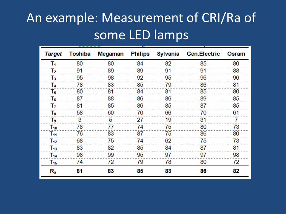
An example: Measurement of CRI/Ra of some LED lamps
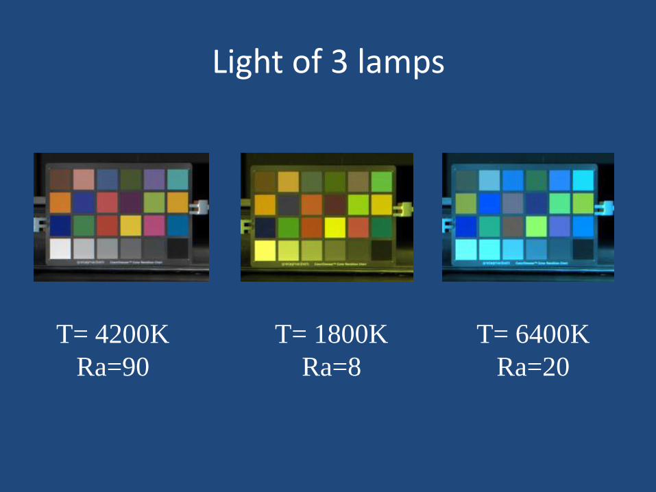
Light of 3 lamps
T= 4200K
Ra=90
T= 1800K
Ra=8
T= 6400K
Ra=20
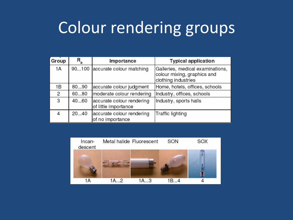
Colour rendering groups
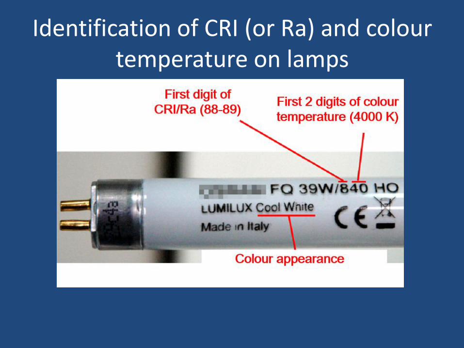
Identification of CRI (or Ra) and colour temperature on lamps
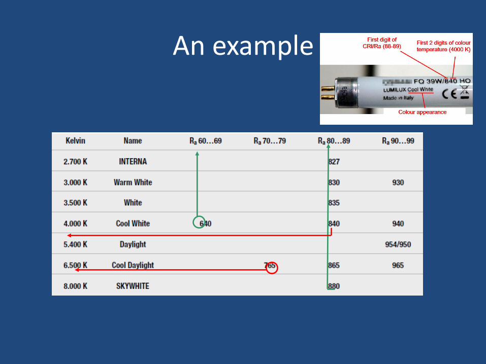
An example
Photometrics
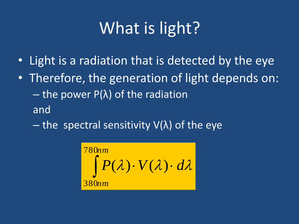
What is light?
• Light is a radiation that is detected by the eye
• Therefore, the generation of light depends on: – the power P(λ) of the radiation
and
– the spectral sensitivity V(λ) of the eye
nm
nm
dVP
780
380
)()(
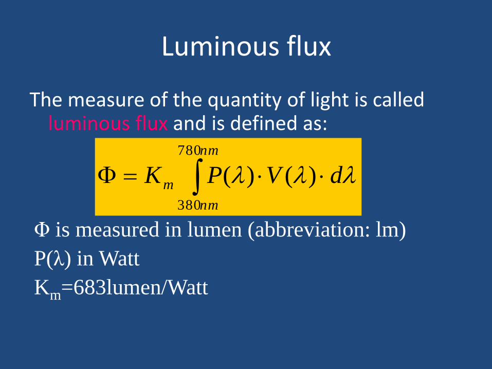
Luminous flux
The measure of the quantity of light is called luminous flux and is defined as:
nm
nm
m dVPK
780
380
)()(
Φ is measured in lumen (abbreviation: lm)
P(λ) in Watt
Km=683lumen/Watt
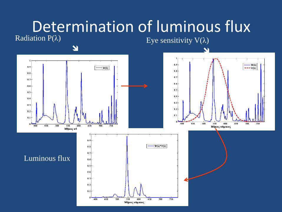
Determination of luminous flux Radiation P(λ)
Eye sensitivity V(λ)
Luminous flux
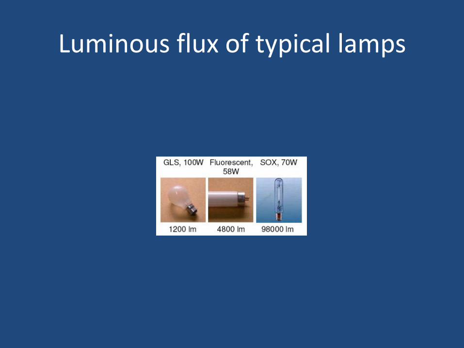
Luminous flux of typical lamps
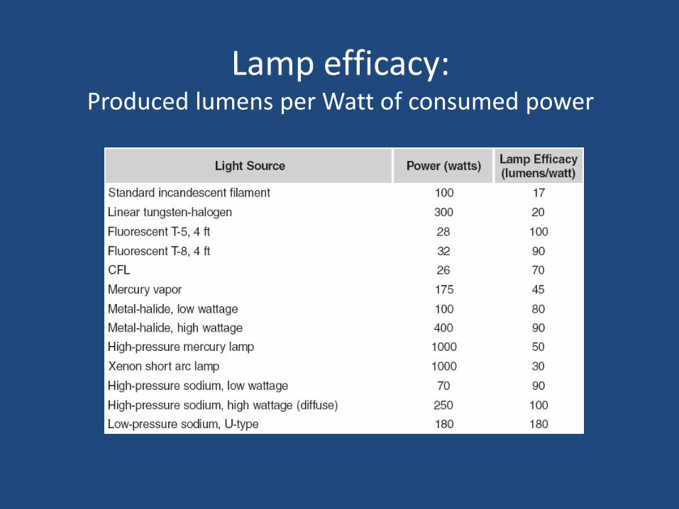
Lamp efficacy: Produced lumens per Watt of consumed power
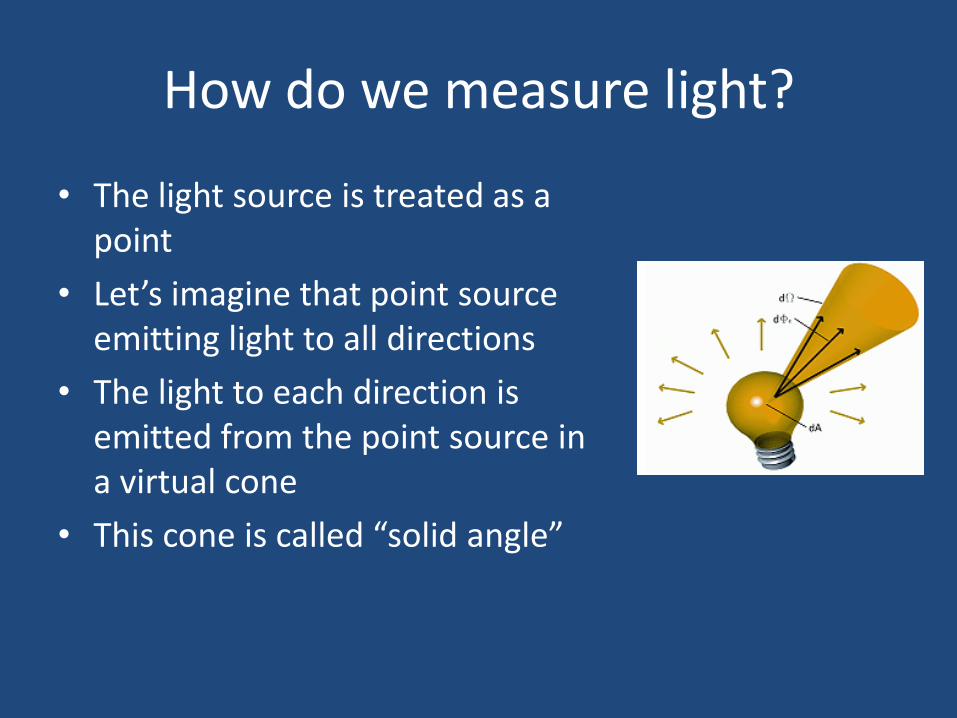
How do we measure light?
• The light source is treated as a point
• Let’s imagine that point source emitting light to all directions
• The light to each direction is emitted from the point source in a virtual cone
• This cone is called “solid angle”
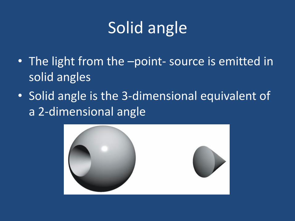
Solid angle
• The light from the –point- source is emitted in solid angles
• Solid angle is the 3-dimensional equivalent of a 2-dimensional angle
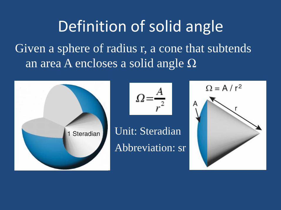
Definition of solid angle Given a sphere of radius r, a cone that subtends
an area A encloses a solid angle Ω
Unit: Steradian
Abbreviation: sr
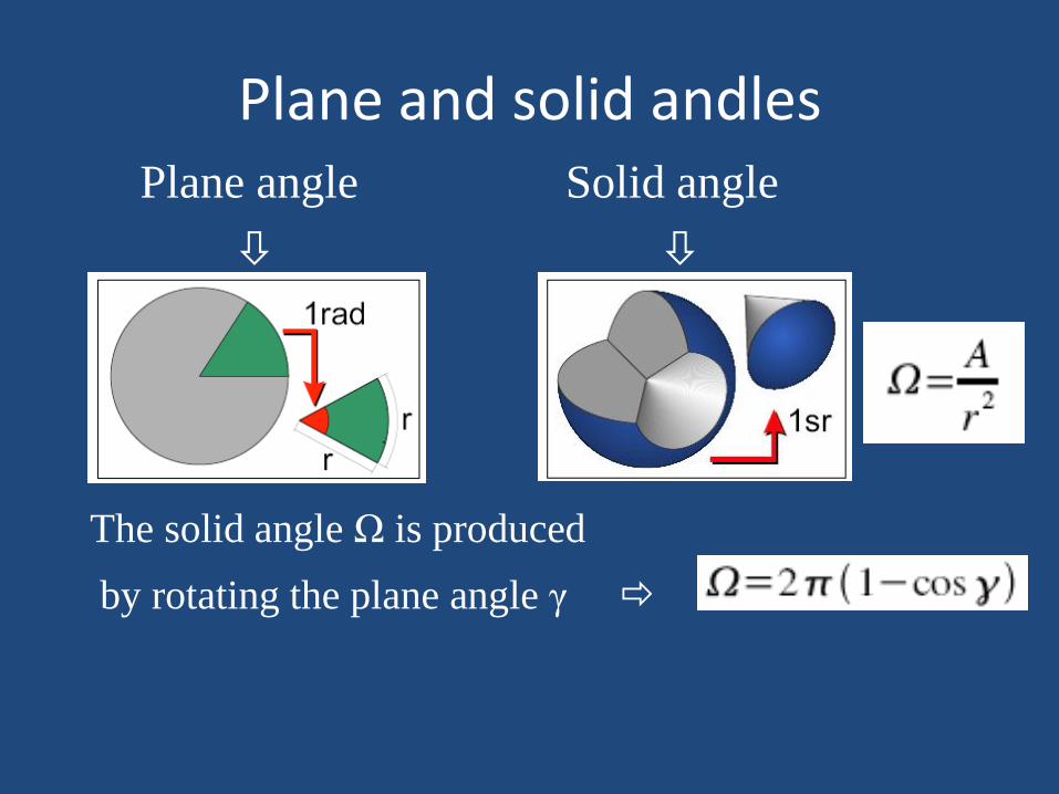
Plane and solid andles Plane angle
Solid angle
The solid angle Ω is produced
by rotating the plane angle γ
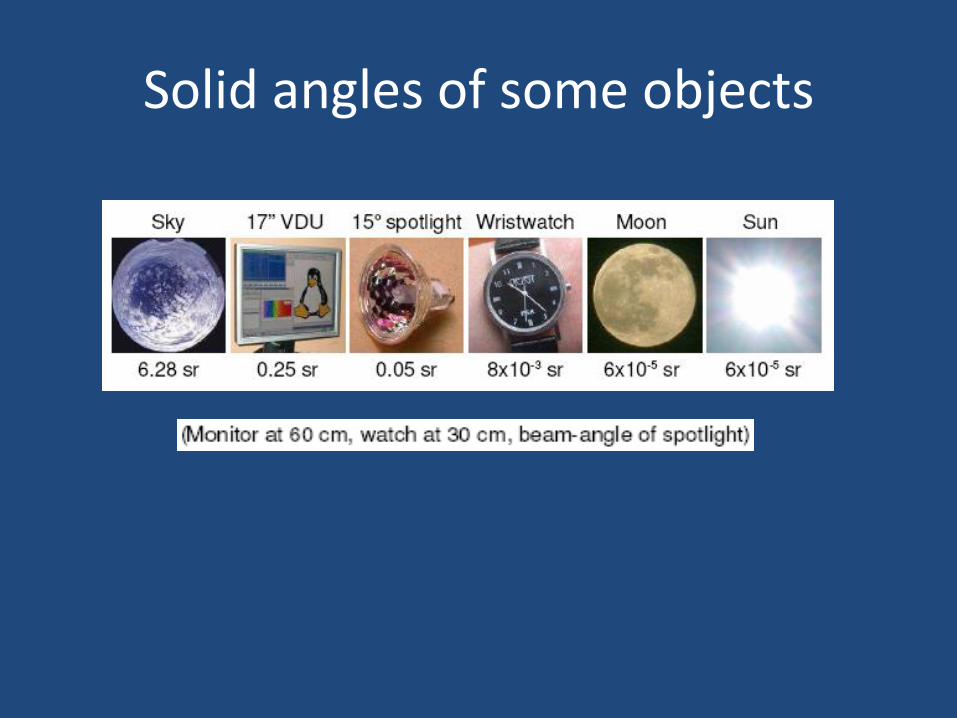
Solid angles of some objects
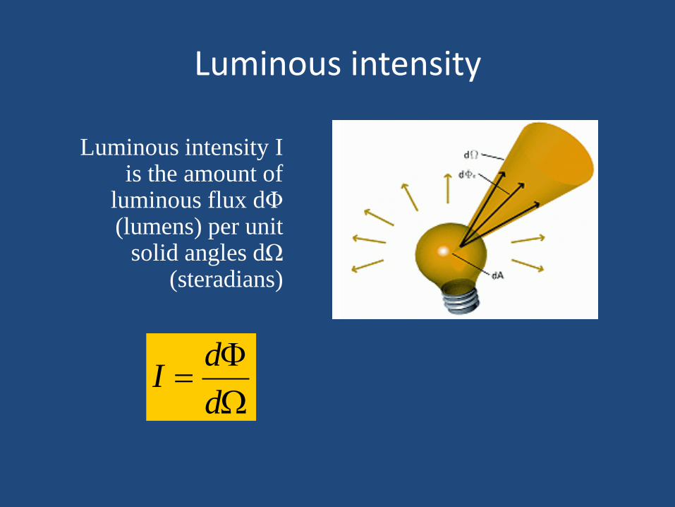
Luminous intensity
Luminous intensity I is the amount of
luminous flux dΦ (lumens) per unit
solid angles dΩ (steradians)
d
dI
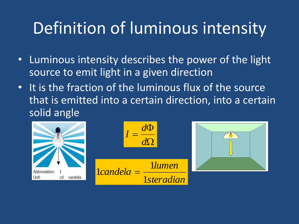
Definition of luminous intensity
• Luminous intensity describes the power of the light source to emit light in a given direction
• It is the fraction of the luminous flux of the source that is emitted into a certain direction, into a certain solid angle
d
dI
steradian
lumencandela
1
11
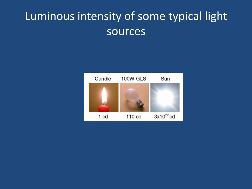
Luminous intensity of some typical light sources
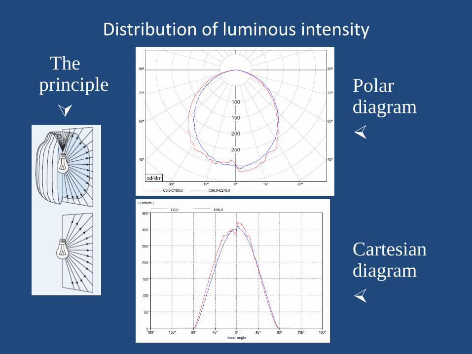
Distribution of luminous intensity
The principle
Polar diagram
Cartesian diagram
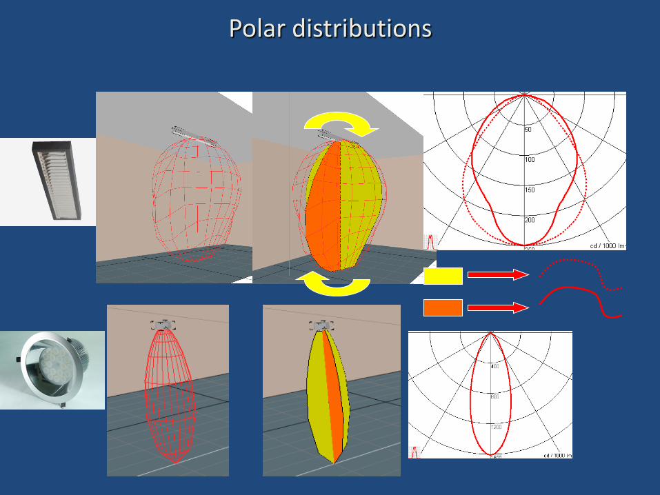
Polar distributions
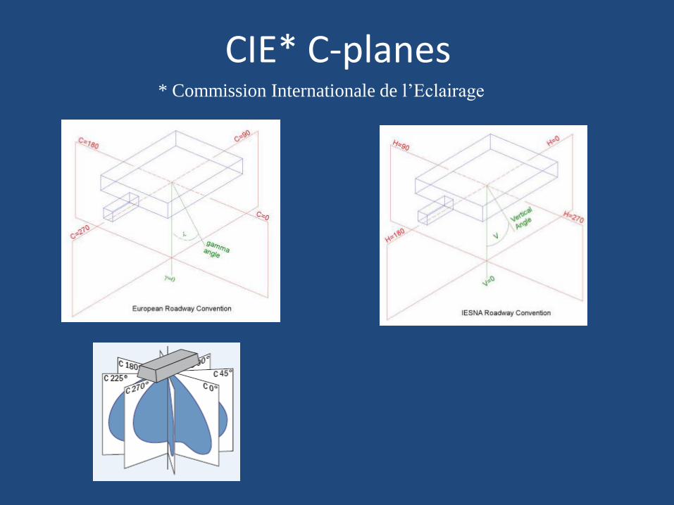
CIE* C-planes * Commission Internationale de l’Eclairage
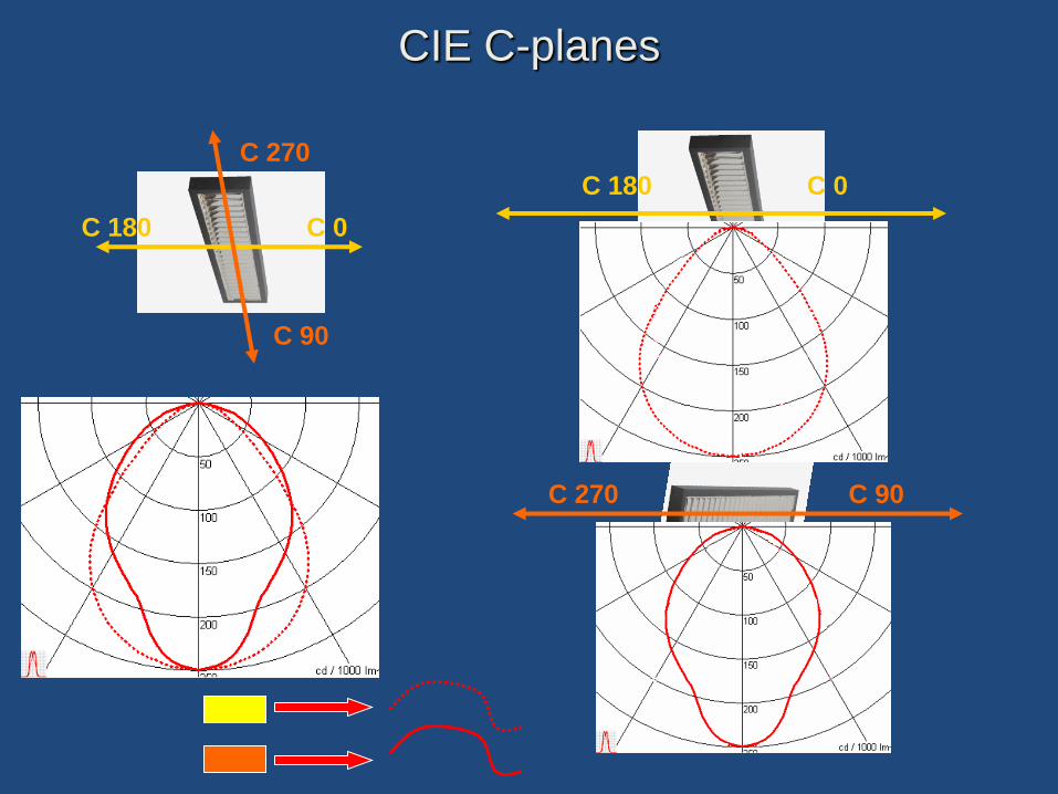
CIE C-planes
C 180 C 0
C 180 C 0
C 90
C 270
C 90 C 270
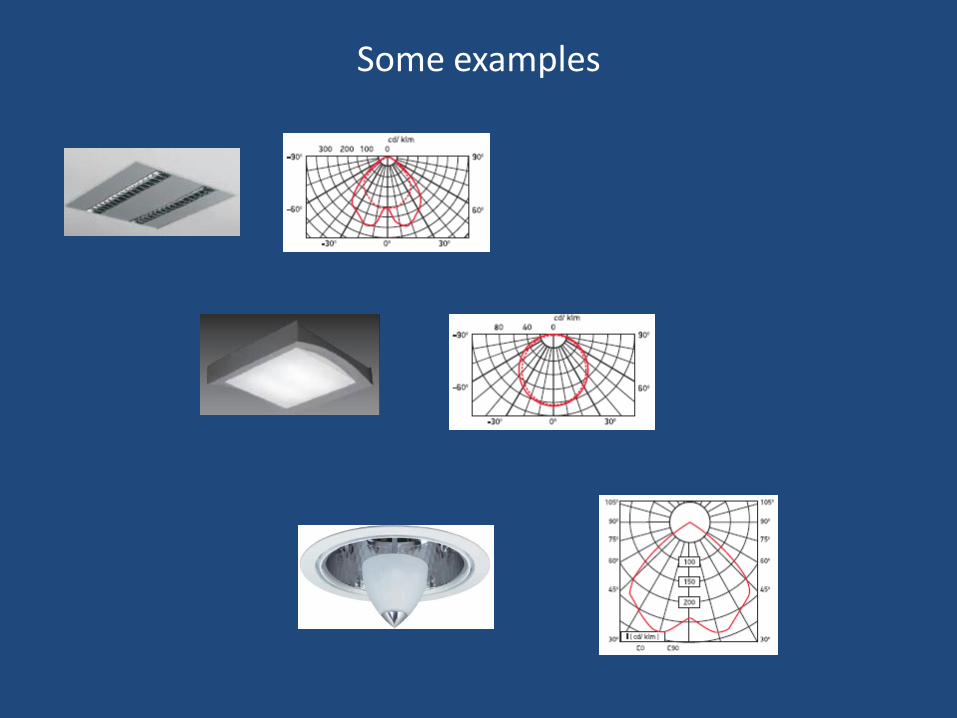
Some examples
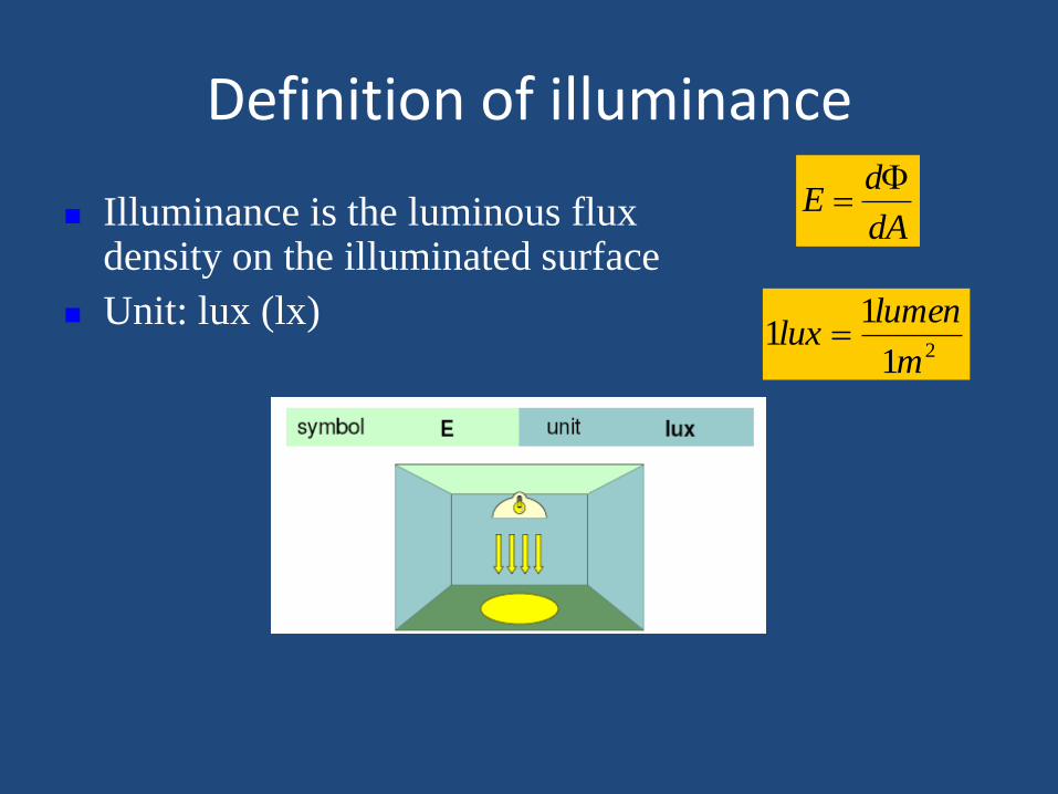
Definition of illuminance
Illuminance is the luminous flux density on the illuminated surface
Unit: lux (lx)
dA
dE
21
11
m
lumenlux
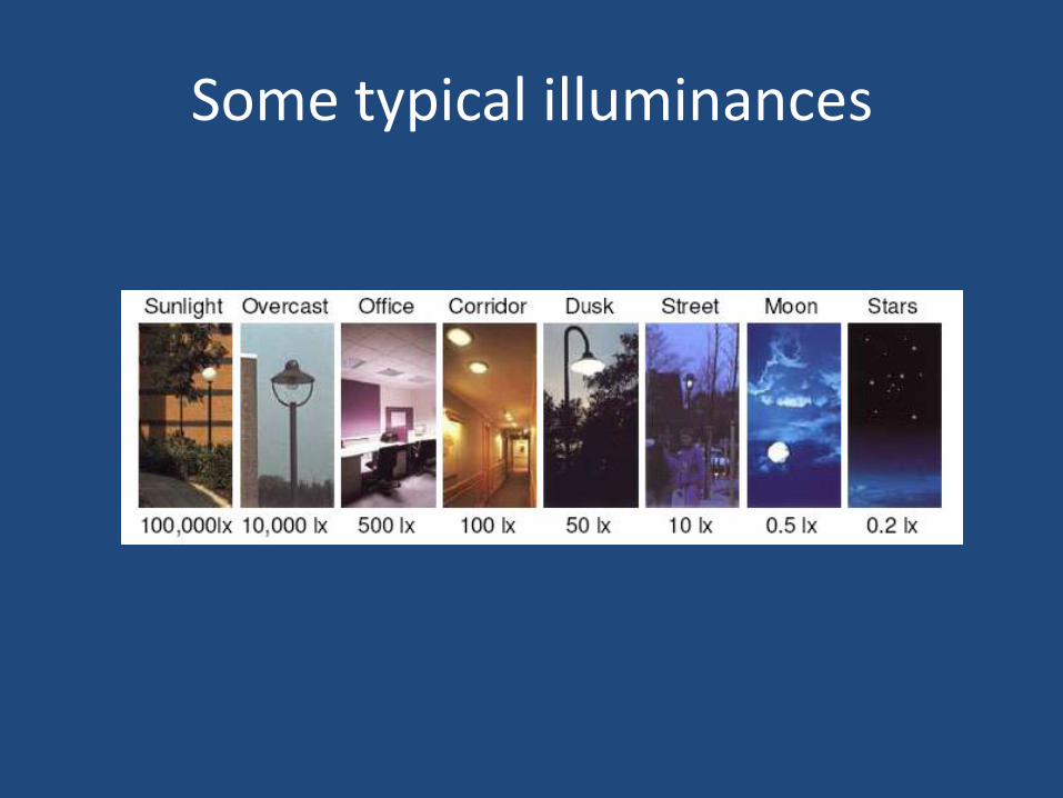
Some typical illuminances
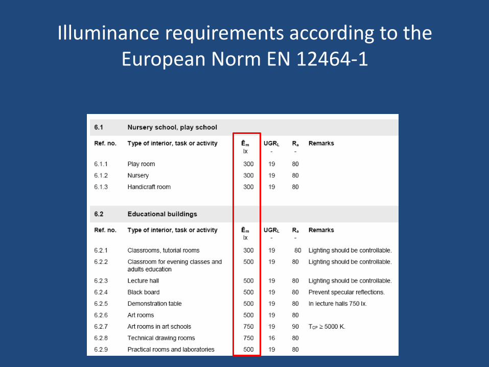
Illuminance requirements according to the European Norm ΕΝ 12464-1
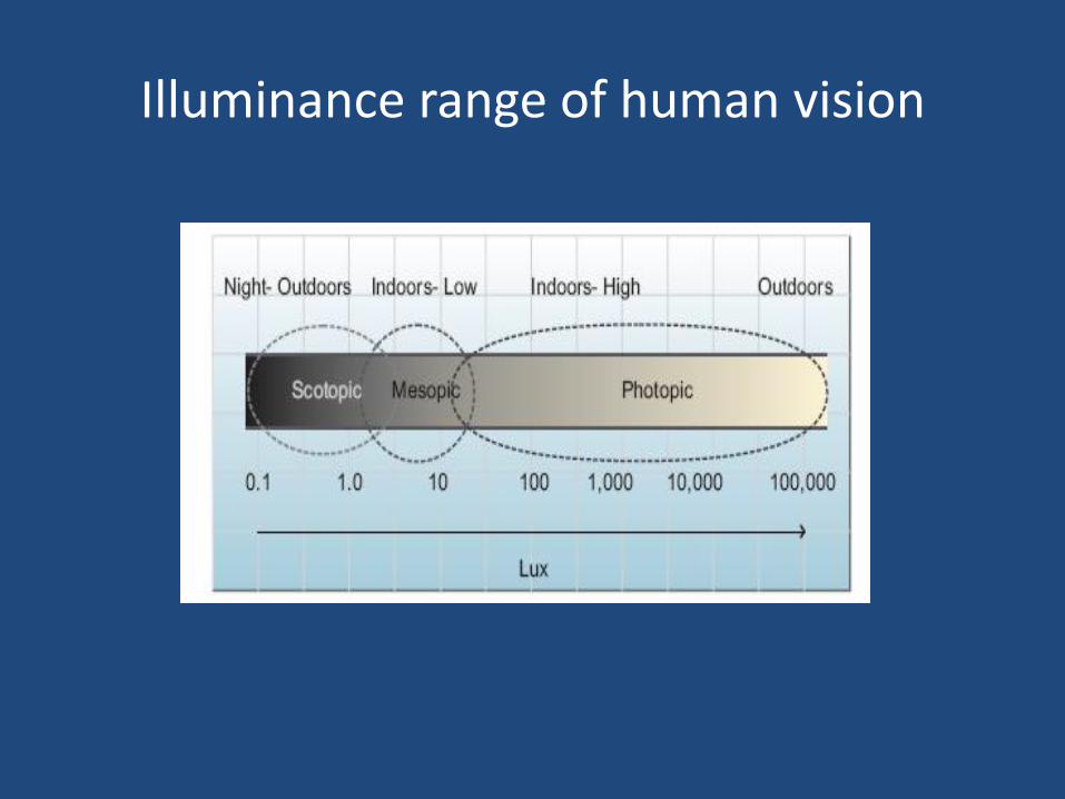
Illuminance range of human vision
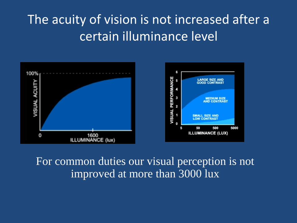
The acuity of vision is not increased after a certain illuminance level
For common duties our visual perception is not improved at more than 3000 lux
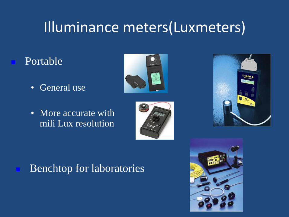
Illuminance meters(Luxmeters)
Portable
• General use
• More accurate with mili Lux resolution
Benchtop for laboratories
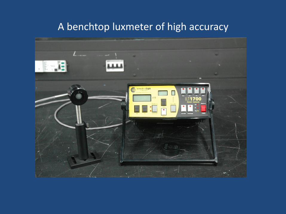
A benchtop luxmeter of high accuracy
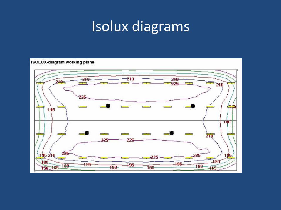
Isolux diagrams
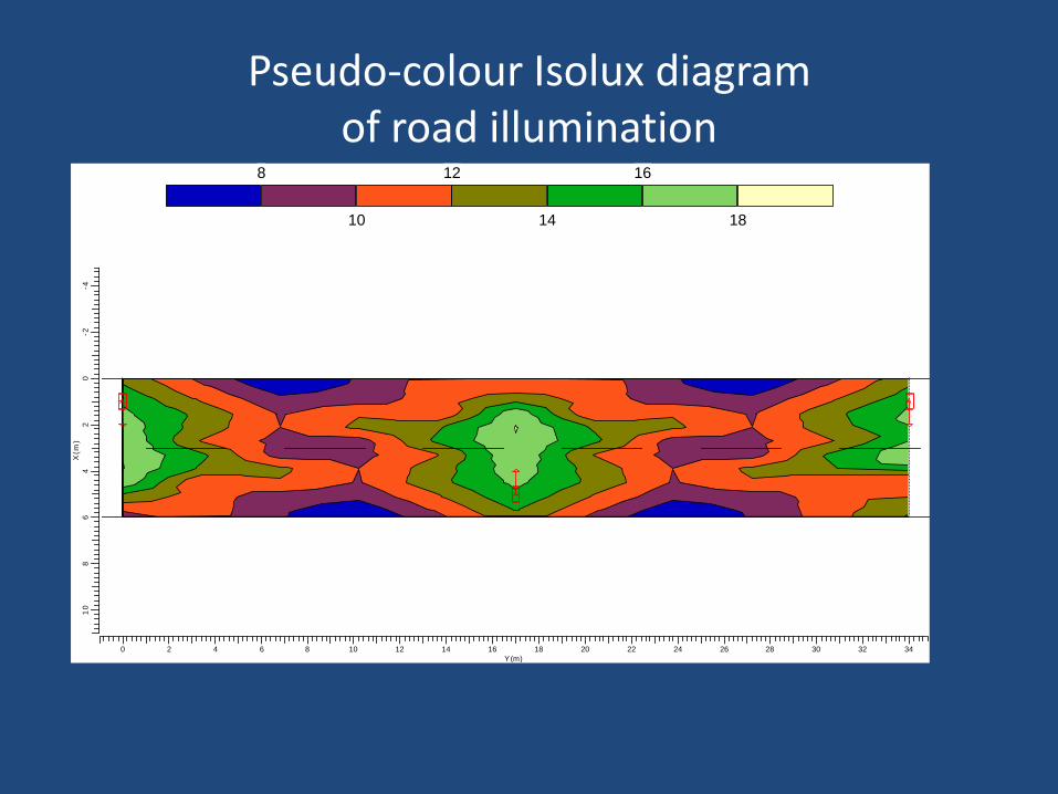
Pseudo-colour Isolux diagram of road illumination
18
16
14
12
10
8
0 2 4 6 8 10 12 14 16 18 20 22 24 26 28 30 32 34
Y(m)
10
86
42
0-2
-4
X(m
)
AAAAAAA
AAAAAAA
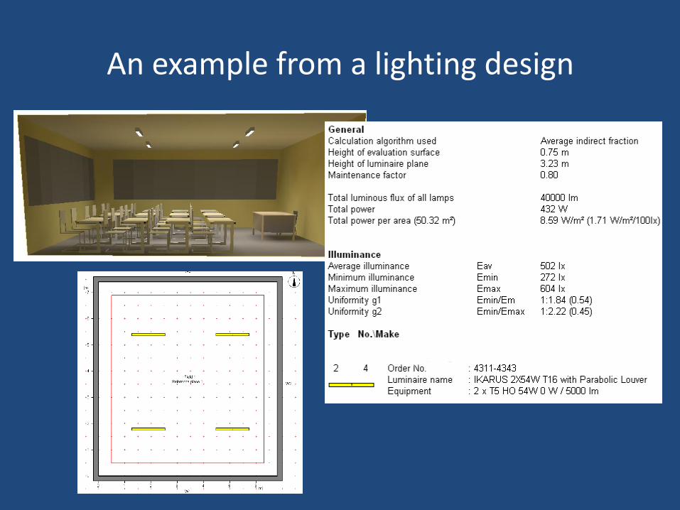
An example from a lighting design
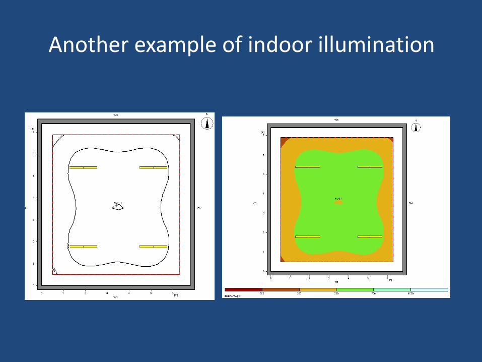
Another example of indoor illumination
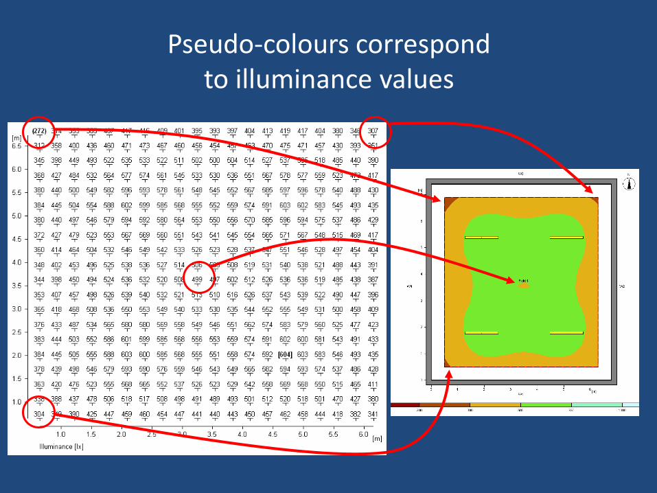
Pseudo-colours correspond to illuminance values
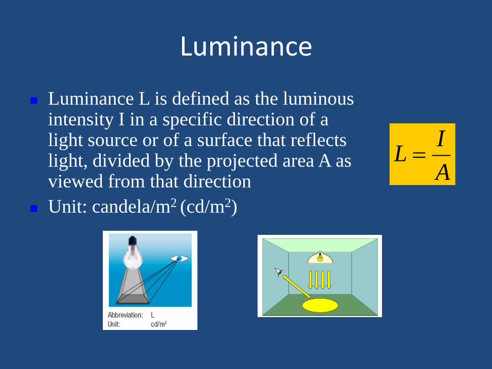
Luminance
Luminance L is defined as the luminous intensity I in a specific direction of a light source or of a surface that reflects light, divided by the projected area A as viewed from that direction
Unit: candela/m2 (cd/m2)
A
IL
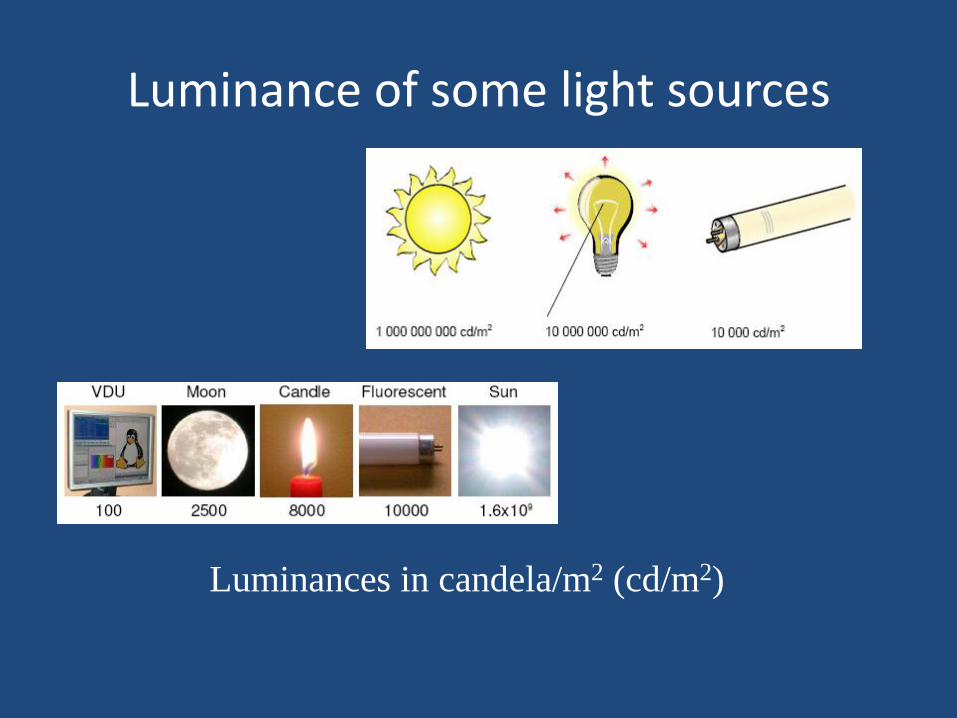
Luminance of some light sources
Luminances in candela/m2 (cd/m2)
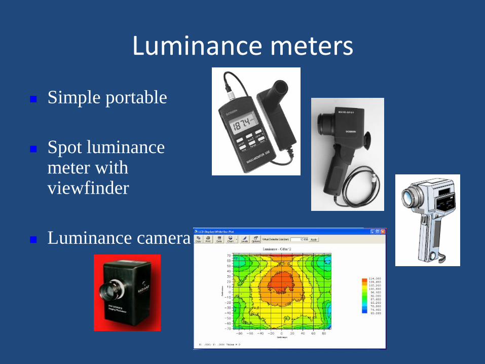
Luminance meters
Simple portable
Spot luminance meter with viewfinder
Luminance camera
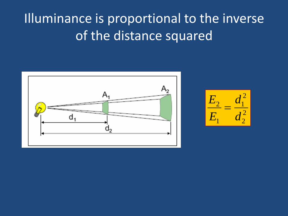
Illuminance is proportional to the inverse of the distance squared
2
2
2
1
1
2
d
d
E
E
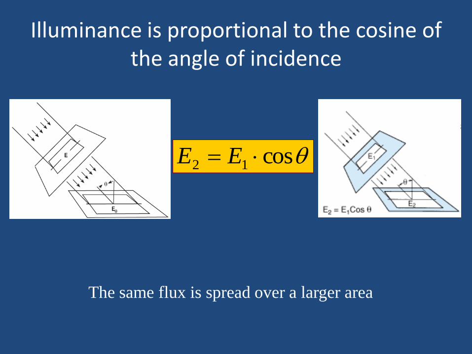
Illuminance is proportional to the cosine of the angle of incidence
cos12 EE
The same flux is spread over a larger area
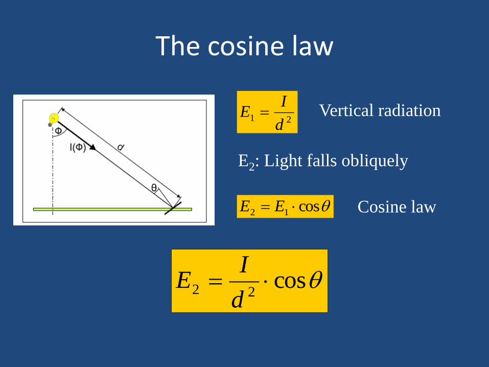
The cosine law
cos12 EE Cosine law
Vertical radiation
21
d
IE
E2: Light falls obliquely
cos22
d
IE
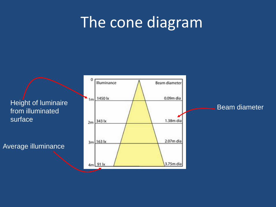
The cone diagram
Height of luminaire
from illuminated
surface
Beam diameter
Average illuminance
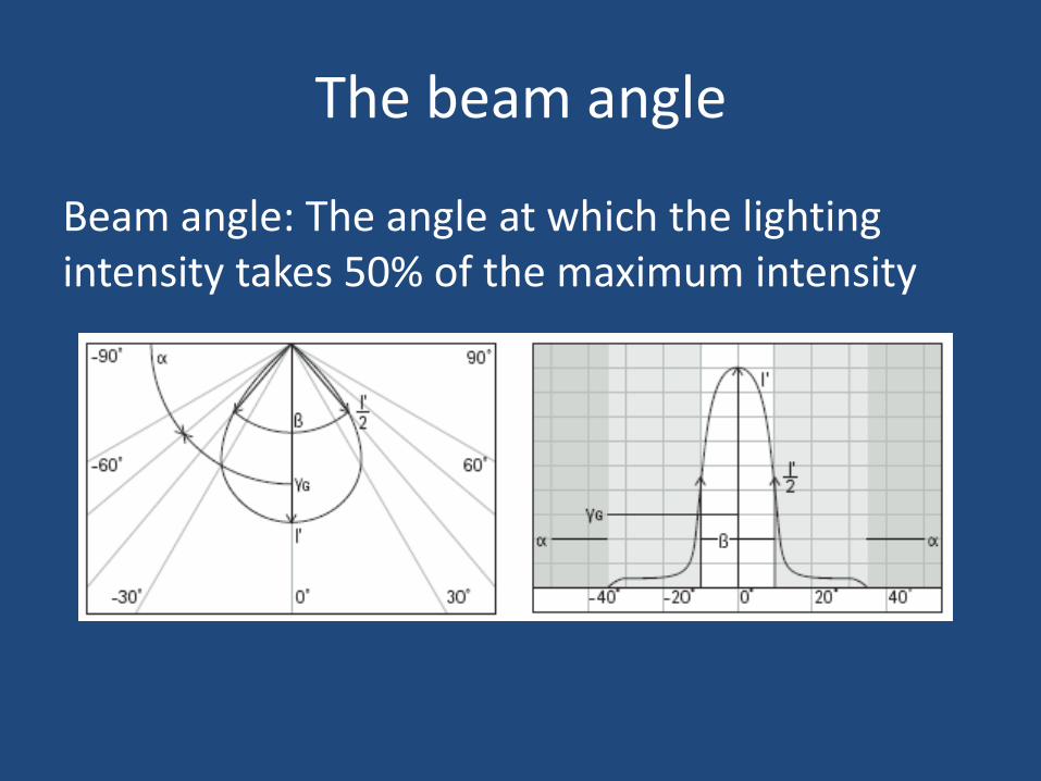
The beam angle
Beam angle: The angle at which the lighting intensity takes 50% of the maximum intensity
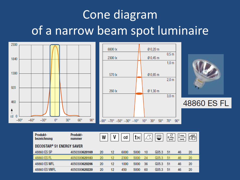
Cone diagram of a narrow beam spot luminaire
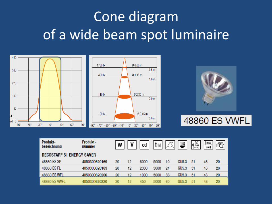
Cone diagram of a wide beam spot luminaire
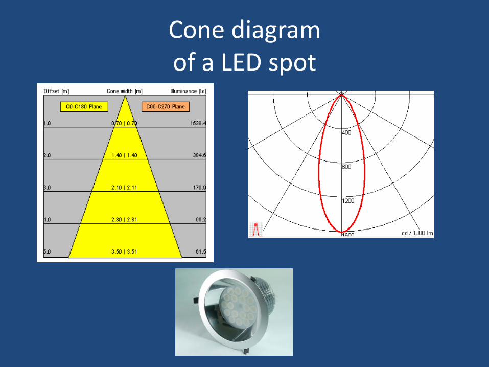
Cone diagram of a LED spot
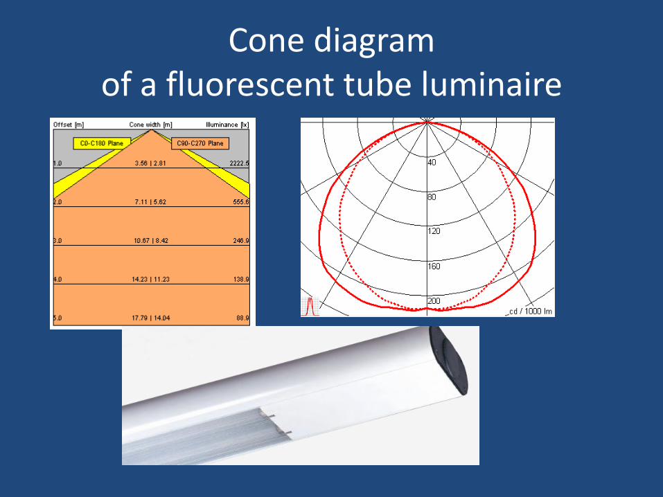
Cone diagram of a fluorescent tube luminaire
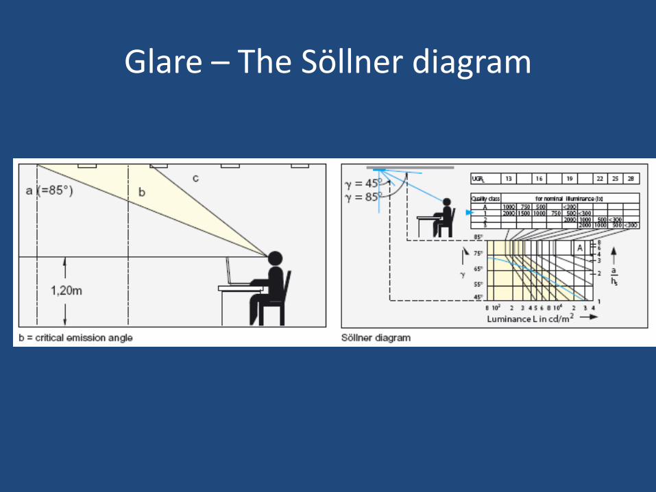
Glare – The Söllner diagram
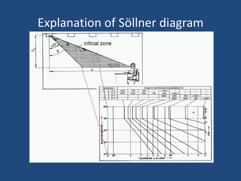
Explanation of Söllner diagram
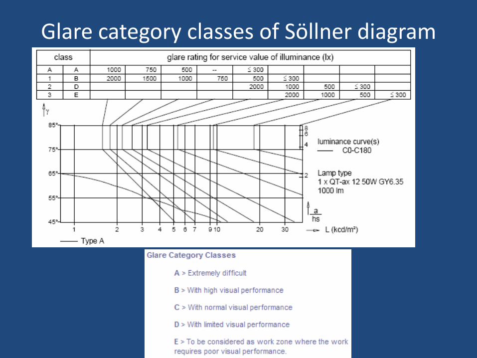
Glare category classes of Söllner diagram
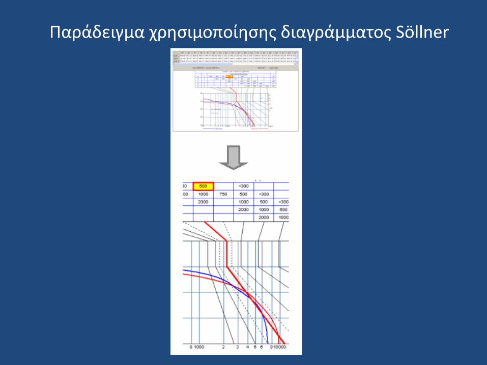
Παράδειγμα χρησιμοποίησης διαγράμματος Söllner
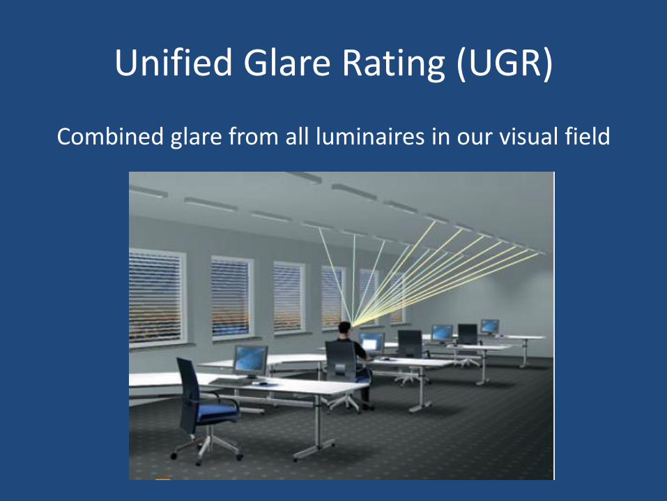
Unified Glare Rating (UGR)
Combined glare from all luminaires in our visual field
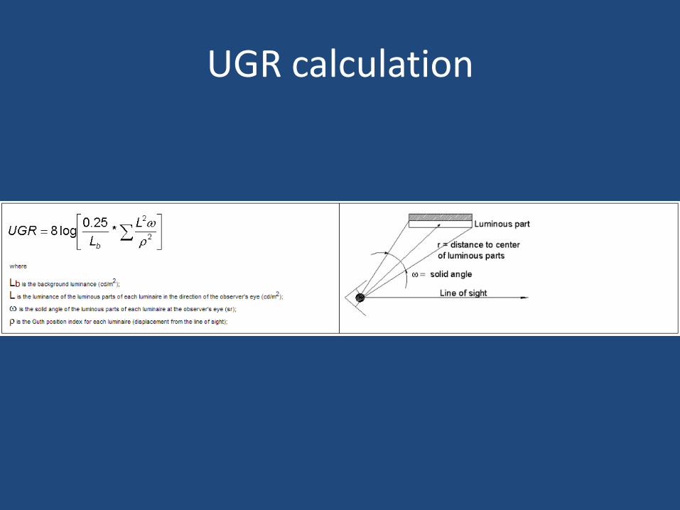
UGR calculation
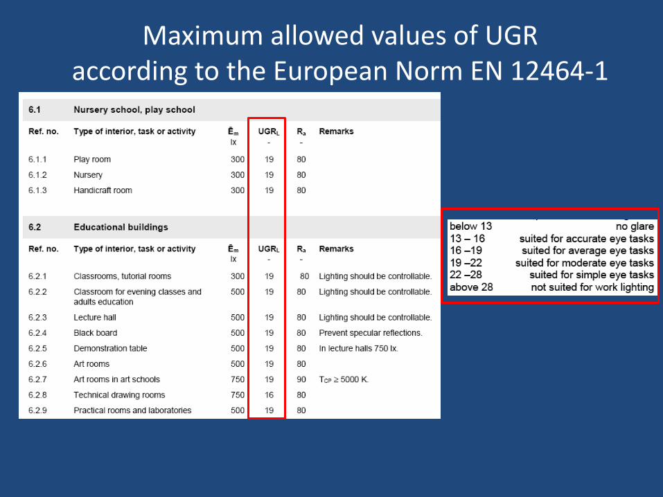
Maximum allowed values of UGR according to the European Norm ΕΝ 12464-1
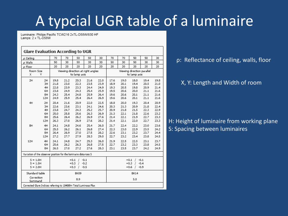
A typcial UGR table of a luminaire
H: Height of luminaire from working plane S: Spacing between luminaires
ρ: Reflectance of ceiling, walls, floor
X, Y: Length and Width of room
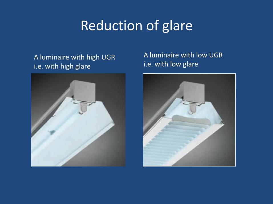
Reduction of glare
A luminaire with high UGR i.e. with high glare
A luminaire with low UGR i.e. with low glare
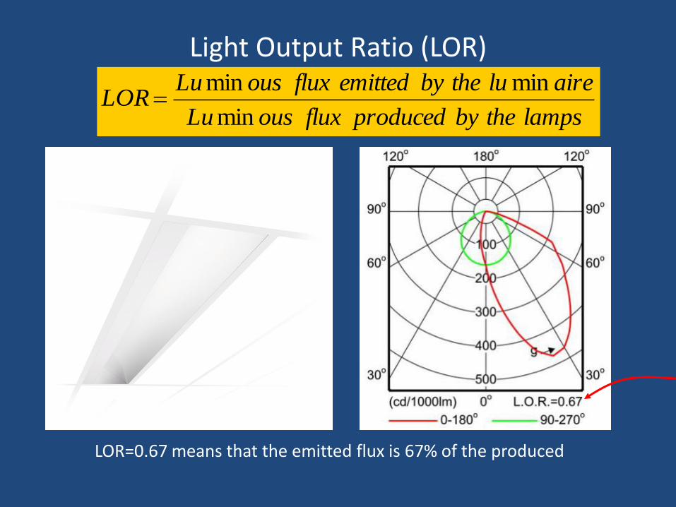
Light Output Ratio (LOR)
LOR=0.67 means that the emitted flux is 67% of the produced
lampsthebyproducedfluxousLu
aireluthebyemittedfluxousLuLOR
min
minmin
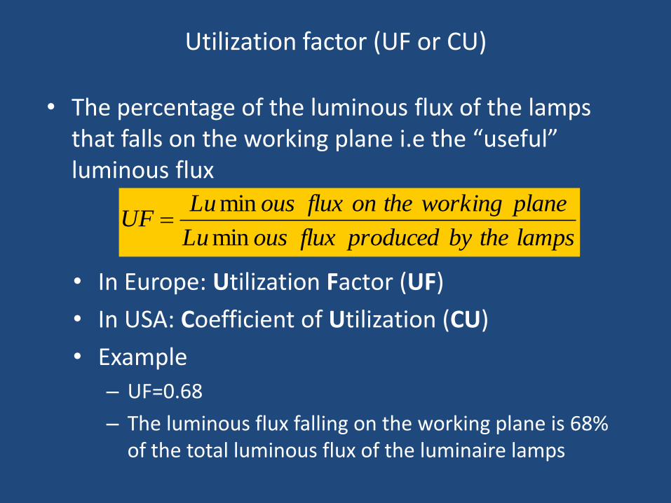
Utilization factor (UF or CU)
• The percentage of the luminous flux of the lamps that falls on the working plane i.e the “useful” luminous flux
lampsthebyproducedfluxousLu
planeworkingtheonfluxousLuUF
min
min
• In Europe: Utilization Factor (UF)
• In USA: Coefficient of Utilization (CU)
• Example
– UF=0.68
– The luminous flux falling on the working plane is 68% of the total luminous flux of the luminaire lamps
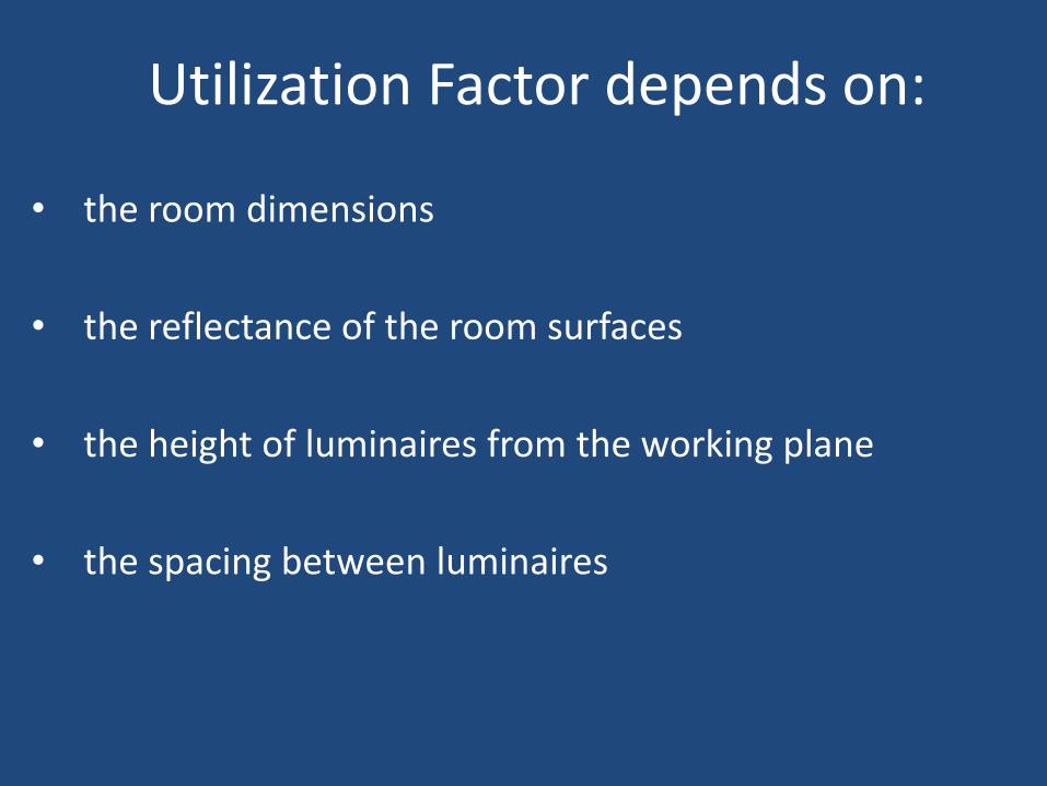
Utilization Factor depends on:
• the room dimensions
• the reflectance of the room surfaces
• the height of luminaires from the working plane
• the spacing between luminaires
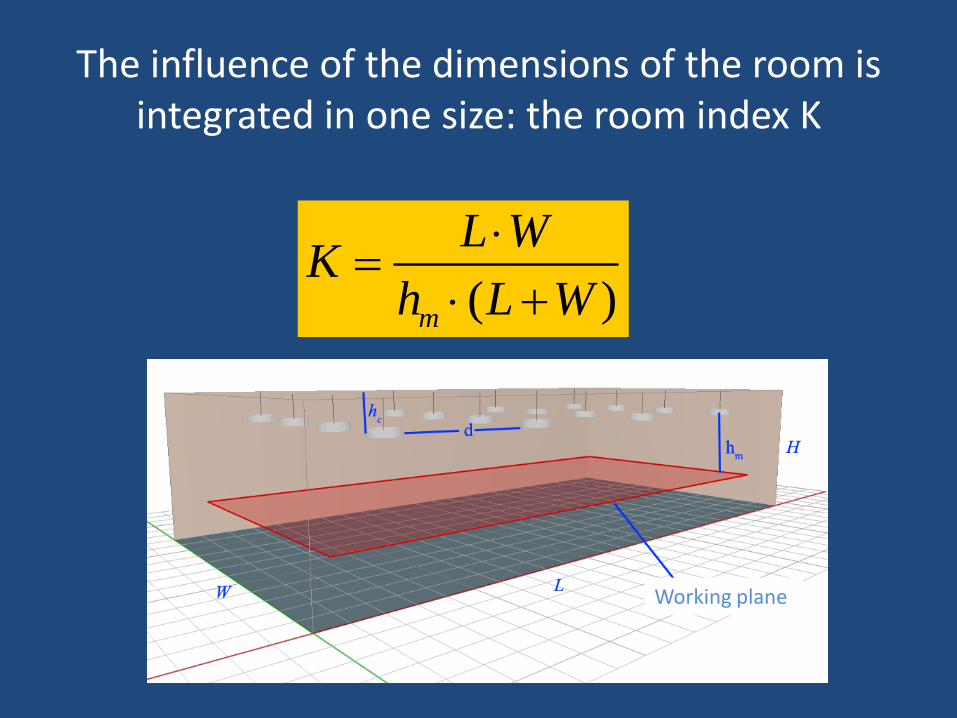
The influence of the dimensions of the room is integrated in one size: the room index Κ
( )m
L WK
h L W
Working plane
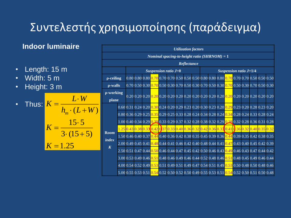
Συντελεστής χρησιμοποίησης (παράδειγμα)
Utilization factors
Nominal spacing-to-height ratio (SHRNOM) = 1
Reflectance
Suspension ratio J=0 Suspension ratio J=1/4
ρ-ceiling 0.80 0.80 0.80 0.70 0.70 0.70 0.50 0.50 0.50 0.80 0.80 0.80 0.70 0.70 0.70 0.50 0.50 0.50
ρ-walls 0.70 0.50 0.30 0.70 0.50 0.30 0.70 0.50 0.30 0.70 0.50 0.30 0.70 0.50 0.30 0.70 0.50 0.30
ρ-working
plane 0.20 0.20 0.20 0.20 0.20 0.20 0.20 0.20 0.20 0.20 0.20 0.20 0.20 0.20 0.20 0.20 0.20 0.20
Room
index
K
0.60 0.31 0.24 0.20 0.30 0.24 0.20 0.29 0.23 0.20 0.30 0.23 0.20 0.29 0.23 0.20 0.28 0.23 0.20
0.80 0.36 0.29 0.25 0.35 0.29 0.25 0.33 0.28 0.24 0.34 0.28 0.24 0.34 0.28 0.24 0.33 0.28 0.24
1.00 0.40 0.34 0.29 0.39 0.33 0.29 0.37 0.32 0.28 0.38 0.32 0.29 0.38 0.32 0.28 0.36 0.31 0.28
1.25 0.43 0.38 0.33 0.42 0.37 0.33 0.40 0.36 0.32 0.42 0.36 0.33 0.41 0.36 0.32 0.40 0.35 0.32
1.50 0.46 0.40 0.37 0.44 0.40 0.36 0.42 0.38 0.35 0.45 0.39 0.36 0.44 0.39 0.35 0.42 0.38 0.35
2.00 0.49 0.45 0.41 0.48 0.44 0.41 0.46 0.42 0.40 0.48 0.44 0.41 0.47 0.43 0.40 0.45 0.42 0.39
2.50 0.51 0.47 0.44 0.50 0.46 0.44 0.47 0.45 0.42 0.50 0.46 0.43 0.49 0.46 0.43 0.47 0.44 0.42
3.00 0.53 0.49 0.46 0.51 0.48 0.46 0.49 0.46 0.44 0.52 0.48 0.46 0.51 0.48 0.45 0.49 0.46 0.44
4.00 0.54 0.52 0.49 0.53 0.51 0.49 0.51 0.49 0.47 0.54 0.51 0.49 0.53 0.50 0.48 0.50 0.48 0.46
5.00 0.55 0.53 0.51 0.54 0.52 0.50 0.52 0.50 0.49 0.55 0.53 0.51 0.54 0.52 0.50 0.51 0.50 0.48
Indoor luminaire
• Length: 15 m
• Width: 5 m
• Height: 3 m
• Thus: ( )
15 5
3 (15 5)
1.25
m
L WK
h L W
K
K
The Maintenance Factor (MF)
113
• The lighting installation is depreciated over the time
(ageing of lamps, depreciation of optical materials, dirt
over the reflecting surfaces etc)
• The lighting designer estimates that depreciation
quantitevely (MF) and increases respectively the initial
lighting level
• Over the time, that lighting level will be decreased due
to the ageing and the dirt.
• Thus, the initially high lighting level will be decreased,
over the time, to a level not lower than the required.
An example
114
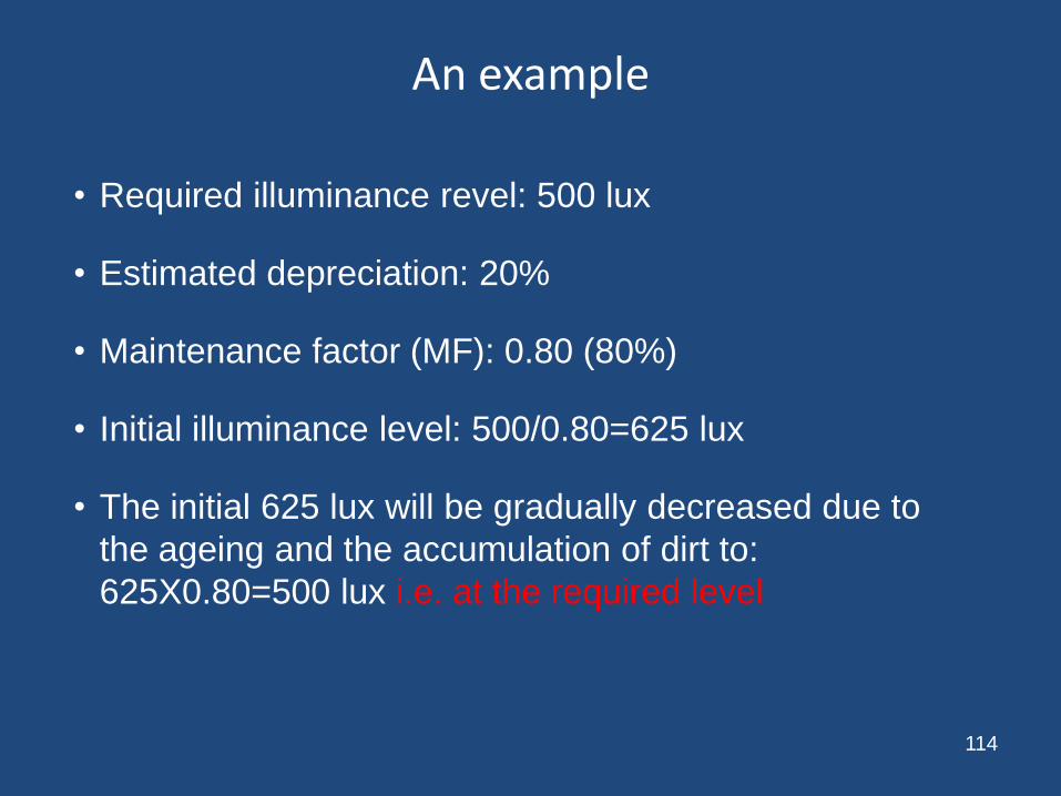
• Required illuminance revel: 500 lux
• Estimated depreciation: 20%
• Maintenance factor (MF): 0.80 (80%)
• Initial illuminance level: 500/0.80=625 lux
• The initial 625 lux will be gradually decreased due to
the ageing and the accumulation of dirt to:
625X0.80=500 lux i.e. at the required level
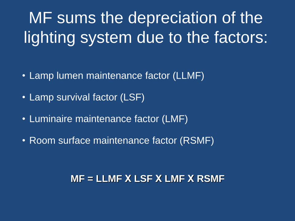
MF sums the depreciation of the
lighting system due to the factors:
• Lamp lumen maintenance factor (LLMF)
• Lamp survival factor (LSF)
• Luminaire maintenance factor (LMF)
• Room surface maintenance factor (RSMF)
MF = LLMF Χ LSF Χ LMF Χ RSMF

First we determine how clean is the room
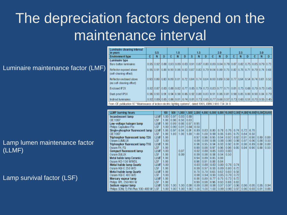
The depreciation factors depend on the
maintenance interval
Luminaire maintenance factor (LMF)
Lamp lumen maintenance factor
(LLMF)
Lamp survival factor (LSF)
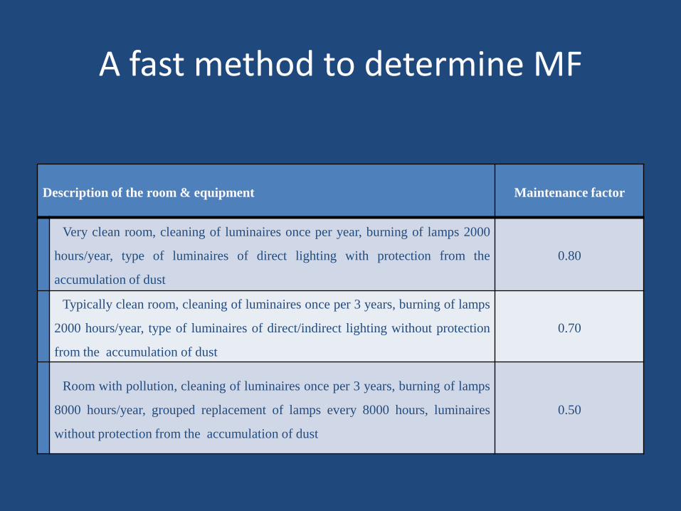
A fast method to determine MF
Description of the room & equipment Maintenance factor
Very clean room, cleaning of luminaires once per year, burning of lamps 2000
hours/year, type of luminaires of direct lighting with protection from the
accumulation of dust
0.80
Typically clean room, cleaning of luminaires once per 3 years, burning of lamps
2000 hours/year, type of luminaires of direct/indirect lighting without protection
from the accumulation of dust
0.70
Room with pollution, cleaning of luminaires once per 3 years, burning of lamps
8000 hours/year, grouped replacement of lamps every 8000 hours, luminaires
without protection from the accumulation of dust
0.50
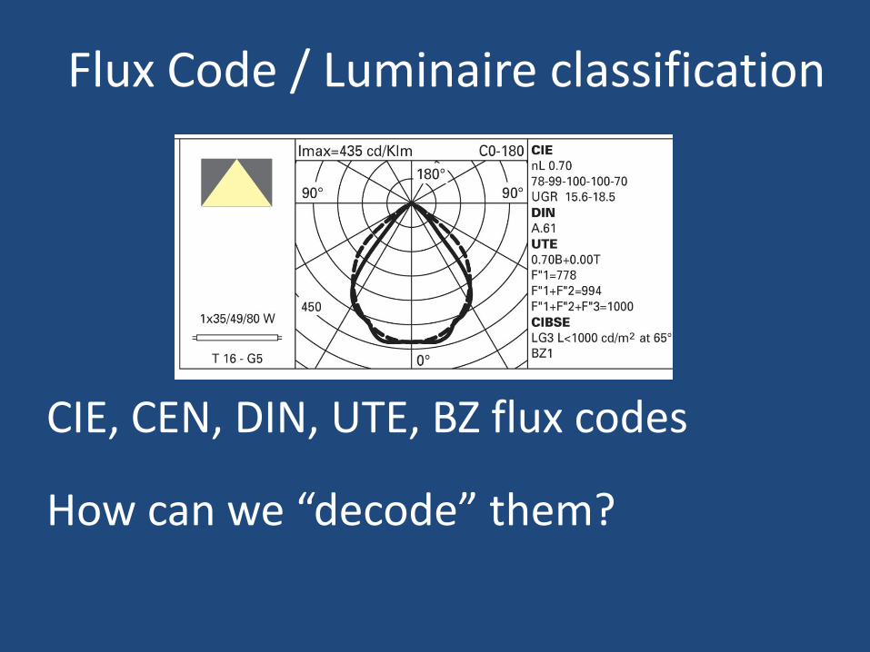
Flux Code / Luminaire classification
CIE, CEN, DIN, UTE, BZ flux codes
How can we “decode” them?
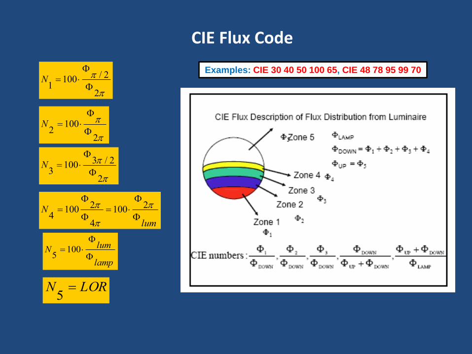
CIE Flux Code
Examples: CIE 30 40 50 100 65, CIE 48 78 95 99 70
2
2/1001
N
2
1002
N
2
2/31003
N
lum
N
2100
4
21004
lamp
lumN
100
5
LORN 5
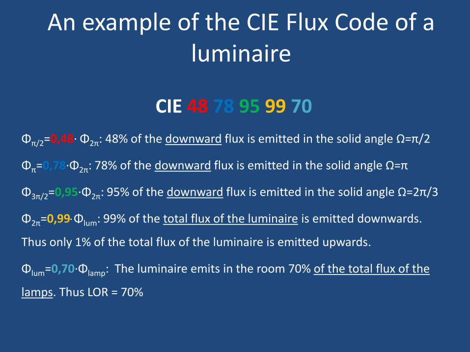
An example of the CIE Flux Code of a luminaire
CIE 48 78 95 99 70
Φπ/2=0,48· Φ2π: 48% of the downward flux is emitted in the solid angle Ω=π/2
Φπ=0,78·Φ2π: 78% of the downward flux is emitted in the solid angle Ω=π
Φ3π/2=0,95·Φ2π: 95% of the downward flux is emitted in the solid angle Ω=2π/3
Φ2π=0,99Φlum: 99% of the total flux of the luminaire is emitted downwards.
Thus only 1% of the total flux of the luminaire is emitted upwards.
Φlum=0,70·Φlamp: The luminaire emits in the room 70% of the total flux of the
lamps. Thus LOR = 70%
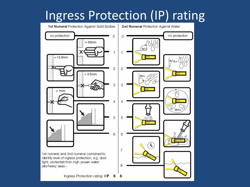
Ingress Protection (IP) rating
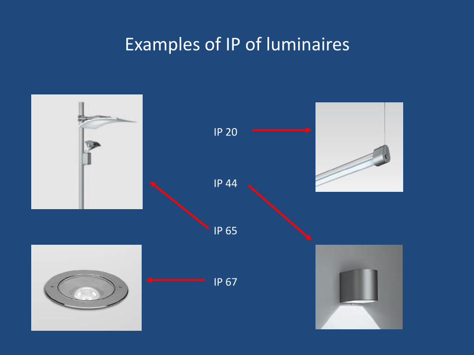
Examples of IP of luminaires
IP 67
IP 65
IP 44
IP 20
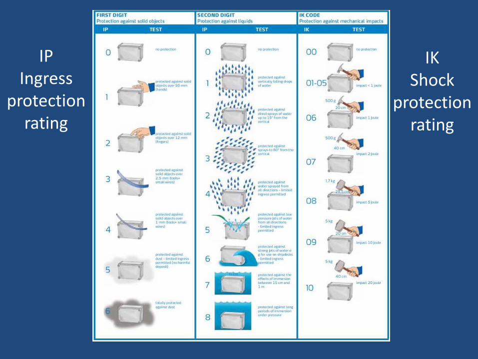
IP Ingress
protection rating
IK Shock
protection rating
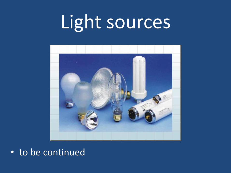
Light sources
• to be continued