Embed Size (px)
Citation preview
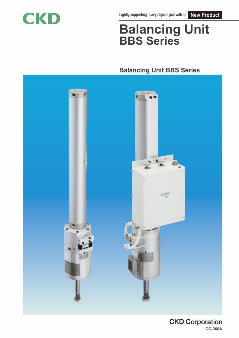
Balancing UnitBBS Series
CC-960A
Lightly supporting heavy objects just with air
Balancing Unit BBS Series
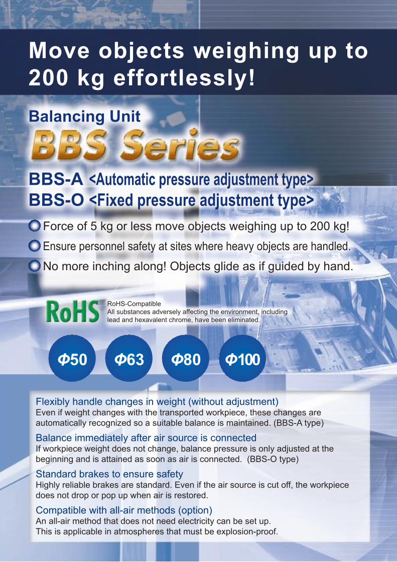
Move objects weighing up to 200 kg effortlessly! Balancing Unit
BBS-A <Automatic pressure adjustment type> BBS-O <Fixed pressure adjustment type>
Force of 5 kg or less move objects weighing up to 200 kg!
Ensure personnel safety at sites where heavy objects are handled.
No more inching along! Objects glide as if guided by hand.
Flexibly handle changes in weight (without adjustment) Even if weight changes with the transported workpiece, these changes areautomatically recognized so a suitable balance is maintained. (BBS-A type)
Balance immediately after air source is connected If workpiece weight does not change, balance pressure is only adjusted at thebeginning and is attained as soon as air is connected. (BBS-O type)
Standard brakes to ensure safety Highly reliable brakes are standard. Even if the air source is cut off, the workpiece does not drop or pop up when air is restored.
Compatible with all-air methods (option) An all-air method that does not need electricity can be set up.This is applicable in atmospheres that must be explosion-proof.
RoHS-CompatibleAll substances adversely affecting the environment, including lead and hexavalent chrome, have been eliminated.
Φ50 Φ63 Φ80 Φ100
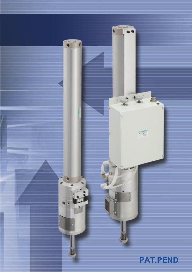
PAT.PEND
Move objects weighing up to 200 kg effortlessly! Balancing Unit
BBS-A <Automatic pressure adjustment type> BBS-O <Fixed pressure adjustment type>
Force of 5 kg or less move objects weighing up to 200 kg!
Ensure personnel safety at sites where heavy objects are handled.
No more inching along! Objects glide as if guided by hand.
Flexibly handle changes in weight (without adjustment) Even if weight changes with the transported workpiece, these changes areautomatically recognized so a suitable balance is maintained. (BBS-A type)
Balance immediately after air source is connected If workpiece weight does not change, balance pressure is only adjusted at thebeginning and is attained as soon as air is connected. (BBS-O type)
Standard brakes to ensure safety Highly reliable brakes are standard. Even if the air source is cut off, the workpiece does not drop or pop up when air is restored.
Compatible with all-air methods (option) An all-air method that does not need electricity can be set up.This is applicable in atmospheres that must be explosion-proof.
RoHS-CompatibleAll substances adversely affecting the environment, including lead and hexavalent chrome, have been eliminated.
Φ50 Φ63 Φ80 Φ100
PAT.PEND

Safety precautionsAlways read this section before starting use.
When designing and manufacturing a device using CKD products, the manufacturer is obligated to check that device safety mechanism, pneumatic control circuit, or water control circuit and the system operated by electrical control that controls the devices is secured. It is important to select, use, handle, and maintain the product appropriately to ensure that the CKD product is used safely. Observe warnings and precautions to ensure device safety. Check that device safety is ensured, and manufacture a safe device.
WARNING1 This product is designed and manufactured as a general industrial machine part.
It must be handled by an operator having sufficient knowledge and experience in handling.
2 Use this product in accordance of specifications. This product must be used within its stated specifications. It must not be modified or machined. This product is intended for use as a general-purpose industrial device or part. It is not intended for use outdoors or for use under the following conditions or environment. (Note that this product can be used when CKD is consulted prior to use and the customer consents to CKD product specifications. The customer must provide safety measures to avoid risks in the event of problems.) 1 Use for special applications including nuclear energy, railway, aircraft, marine vessel, vehicle, medicinal devices, devices or applications coming into
contact with beverages or foodstuffs, amusement devices, emergency cutoff circuits, press machines, brake circuits, or safety devices or applications.2 Use for applications where life or assets could be adversely affected, and special safety measures are required.
3 Observe corporate standards and regulations, etc., related to the safety of device design and control, etc. ISO4414, JIS B8370 (pneumatic system rules)JFPS2008 (principles for pneumatic cylinder selection and use)Including High Pressure Gas Maintenance Law, Occupational Safety and Sanitation Laws, other safety rules, body standards and regulations, etc.
4 Do not handle, pipe, or remove devices before confirming safety. 1 Inspect and service the machine and devices after confirming safety of the entire system related to this
product. 2 Note that there may be hot or charged sections even after operation is stopped. 3 When inspecting or servicing the device, turn off the energy source (air supply or water supply), and turn off power to the facility.
Discharge any compressed air from the system, and pay enough attention to possible water leakage and leakage of electricity. 4 When starting or restarting a machine or device that incorporates pneumatic components, make sure that
the system safety, such as pop-out prevention measures, is secured.
5 Observe warnings and cautions on the pages below to prevent accidents.
The safety cautions are ranked as "DANGER", "WARNING" and "CAUTION" in this section.
DANGER: When a dangerous situation may occur if handling is mistaken leading to fatal or serious injuries, or when there is a high degree of emergency to a warning.
WARNING: When a dangerous situation may occur if handling is mistaken leading to fatal or serious injuries.
CAUTION: When a dangerous situation may occur if handling is mistaken leading to minor injuries or physical damage.
Note that some items described as “CAUTION” may lead to serious results depending on the situation. In any case, important information that must be observed is explained.
Disclaimer1. CKD cannot be held liable for any business interruption, loss of profit, personal injury, delay cost, or any other
ancillary or indirect loss, cost, or damage resulting from the use of or faults in the use of CKD products. 2. CKD cannot be held responsible for the following damage.
1 Damage resulting from disaster or failure of CKD parts due to fire from reasons not attributable to CKD, or by intentional or negligence of a third party or customer.
2 When a CKD product is assembled into customer equipment, damage that could have been avoided if customer equipment were provided with functions and structure, etc., generally accepted in the industry.
3 Damage resulting from use exceeding the scope of specifications provided in CKD catalogs or instruction manuals, etc., or from actions not following precautions for installation, adjustment, or maintenance, etc.
4 Damage resulting from product modifications not approved by CKD, or from faults due to combination with other software or other connected devices.
Intro 1
Pneumatic components
Safety precautionsAlways read this section before starting use. Refer to "Pneumatic Cylinders I (No. CB-29SA)" for the general cylinder or cylinder switch.
Balancing Unit BBS Series
Design & Selection
Intro 2
The va lve or cy l inder cou ld mal func t ion i f carbonized compressor oil (carbon or tar, etc.) enters the c i rcu i t . Serv ice and inspect the compressor carefully.
This cylinder does not need oil. Oiling it could cause problems.
Installation & Adjustment
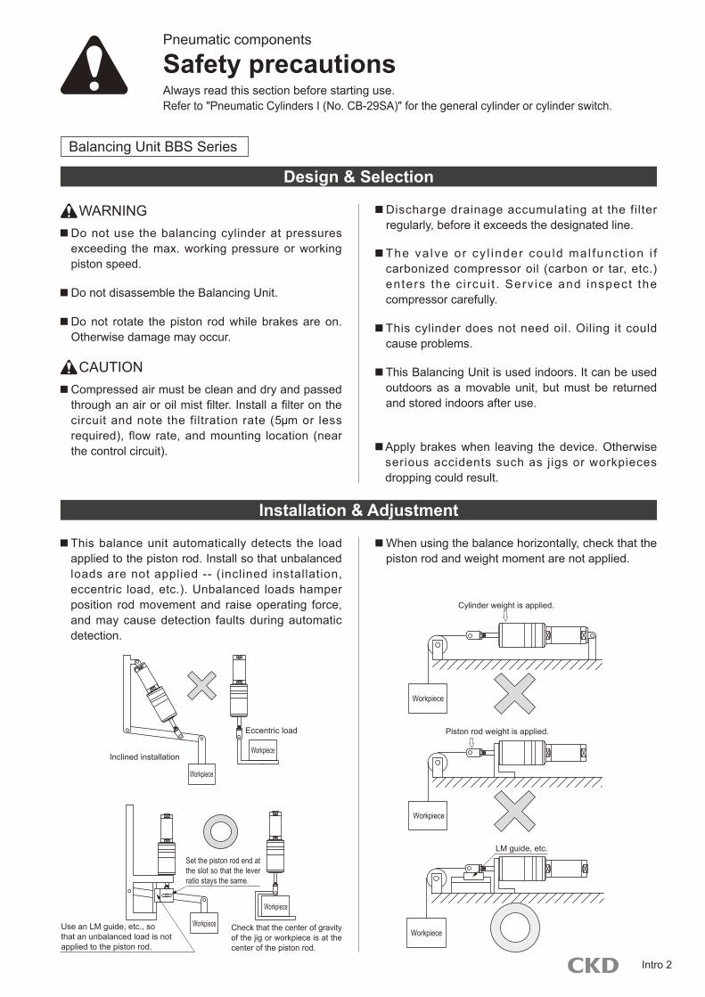
When using the balance horizontally, check that the piston rod and weight moment are not applied.
This balance unit automatically detects the load applied to the piston rod. Install so that unbalanced loads are not applied -- (inclined installation, eccentric load, etc.). Unbalanced loads hamper position rod movement and raise operating force, and may cause detection faults during automatic detection.
Do not use the balancing cylinder at pressures exceeding the max. working pressure or working piston speed.
WARNING
Do not disassemble the Balancing Unit.
Compressed air must be clean and dry and passed through an air or oil mist filter. Install a filter on the circuit and note the filtration rate (5 m or less required), flow rate, and mounting location (near the control circuit).
CAUTION
Discharge drainage accumulating at the filter regularly, before it exceeds the designated line.
This Balancing Unit is used indoors. It can be used outdoors as a movable unit, but must be returned and stored indoors after use.
Apply brakes when leaving the device. Otherwise serious accidents such as jigs or workpieces dropping could result.
Do not rotate the piston rod while brakes are on. Otherwise damage may occur.
Eccentric load
Inclined installation
Workpiece
Workpiece
Use an LM guide, etc., so that an unbalanced load is not applied to the piston rod.
Check that the center of gravity of the jig or workpiece is at the center of the piston rod.
Set the piston rod end at the slot so that the lever ratio stays the same.
Workpiece
Cylinder weight is applied.
Workpiece
Workpiece
LM guide, etc.
Workpiece
Piston rod weight is applied.
Workpiece
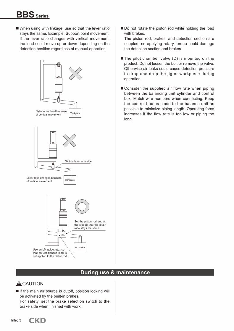
When using with linkage, use so that the lever ratio stays the same. Example: Support point movement: If the lever ratio changes with vertical movement, the load could move up or down depending on the detection position regardless of manual operation.
Do not rotate the piston rod while holding the load with brakes. The piston rod, brakes, and detection section are coupled, so applying rotary torque could damage the detection section and brakes.
During use & maintenance
CAUTION If the main air source is cutoff, position locking will be activated by the built-in brakes. For safety, set the brake selection switch to the brake side when finished with work.
Intro 3
BBS Series
The pilot chamber valve (D) is mounted on the product. Do not loosen the bolt or remove the valve. Otherwise air leaks could cause detection pressure to drop and drop the j ig or workpiece during operation.
Consider the supplied air flow rate when piping between the balancing unit cylinder and control box. Match wire numbers when connecting. Keep the control box as close to the balance unit as possible to minimize piping length. Operating force increases if the flow rate is too low or piping too long.
Workpiece
Workpiece
Workpiece
Cylinder inclined because of vertical movement
Lever ratio changes because of vertical movement
Slot on lever arm side
Use an LM guide, etc., so that an unbalanced load is not applied to the piston rod.
Set the piston rod end at the slot so that the lever ratio stays the same.

Intro 4
M E M OM E M O

Balancing cylinderAutomatic pressure adjustment type
BBS-A Series Bore size: ø50, ø63, ø80, ø100
Specifications
Note 1: Refer to page 11 on the max. load range information for BBS working pressure.
Model no.Descriptions
BBS-A-50 BBS-A-63 BBS-A-80 BBS-A-100
Working fluid Filtrated airMax. working pressure MPa 0.60Min. working pressure MPa 0.25Withstanding pressure MPa 0.90Ambient temperature °C -5 to 50 (no freezing)Bore size mm ø50 ø63 ø80 ø100Max. stroke length mm 1500Working piston speed mm/s 1 to 200Cushion Rubber cushionLubrication Do not lubricate.Necessary min. load kg 10 16 25 40Max. load range Note 1 kg 70 115 180 285Operating force N Refer to page 11 for BBS operating force information.Holding force N 1539 3940
Stroke lengthStandard stroke length (mm) Max. stroke length (mm) Min. stroke length (mm)
100, 200, 300, 400, 500, 600, 700, 800, 900, 1000, 1100, 1200, 1300, 1400, 1500
1500 100
1
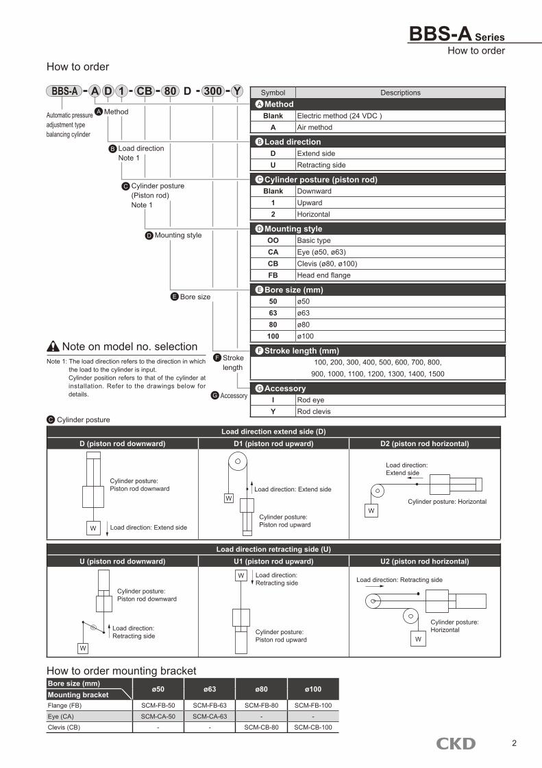
BBS-A SeriesHow to order
Note on model no. selectionNote 1: The load direction refers to the direction in which
the load to the cylinder is input. Cylinder position refers to that of the cylinder at installation. Refer to the drawings below for details.
Automatic pressure adjustment typebalancing cylinder
How to order
BBS-A D Symbol DescriptionsMethodBlank Electric method (24 VDC )
A Air method
Load directionD Extend sideU Retracting side
Cylinder posture (piston rod)Blank Downward
1 Upward2 Horizontal
Mounting styleOO Basic typeCA Eye (ø50, ø63)CB Clevis (ø80, ø100)FB Head end flange
Bore size (mm)50 ø5063 ø6380 ø80100 ø100
Stroke length (mm)100, 200, 300, 400, 500, 600, 700, 800,
900, 1000, 1100, 1200, 1300, 1400, 1500
AccessoryI Rod eyeY Rod clevis
A
B
C
D
F
E
C Cylinder posture
Load direction retracting side (U)U (piston rod downward) U1 (piston rod upward) U2 (piston rod horizontal)
Load direction extend side (D)D (piston rod downward) D1 (piston rod upward) D2 (piston rod horizontal)
Bore size (mm)ø50 ø63 ø80 ø100
Mounting bracketFlange (FB) SCM-FB-50 SCM-FB-63 SCM-FB-80 SCM-FB-100
Eye (CA) SCM-CA-50 SCM-CA-63 - -
Clevis (CB) - - SCM-CB-80 SCM-CB-100
GAccessoryG
Strokelength
F
Bore sizeE
Mounting styleD
Cylinder posture(Piston rod) Note 1
C
Load directionNote 1
B
1 CB 80 Y300
How to order mounting bracket
MethodA
DA
2
Cylinder posture:Piston rod downward
Load direction: Extend sideW
WLoad direction: Extend side
Cylinder posture:Piston rod upward
W
Load direction: Extend side
Cylinder posture: Horizontal
Cylinder posture:Piston rod downward
Load direction: Retracting side
W
Load direction: Retracting side
W
Cylinder posture:Piston rod upward
Load direction: Retracting side
Cylinder posture: Horizontal
W
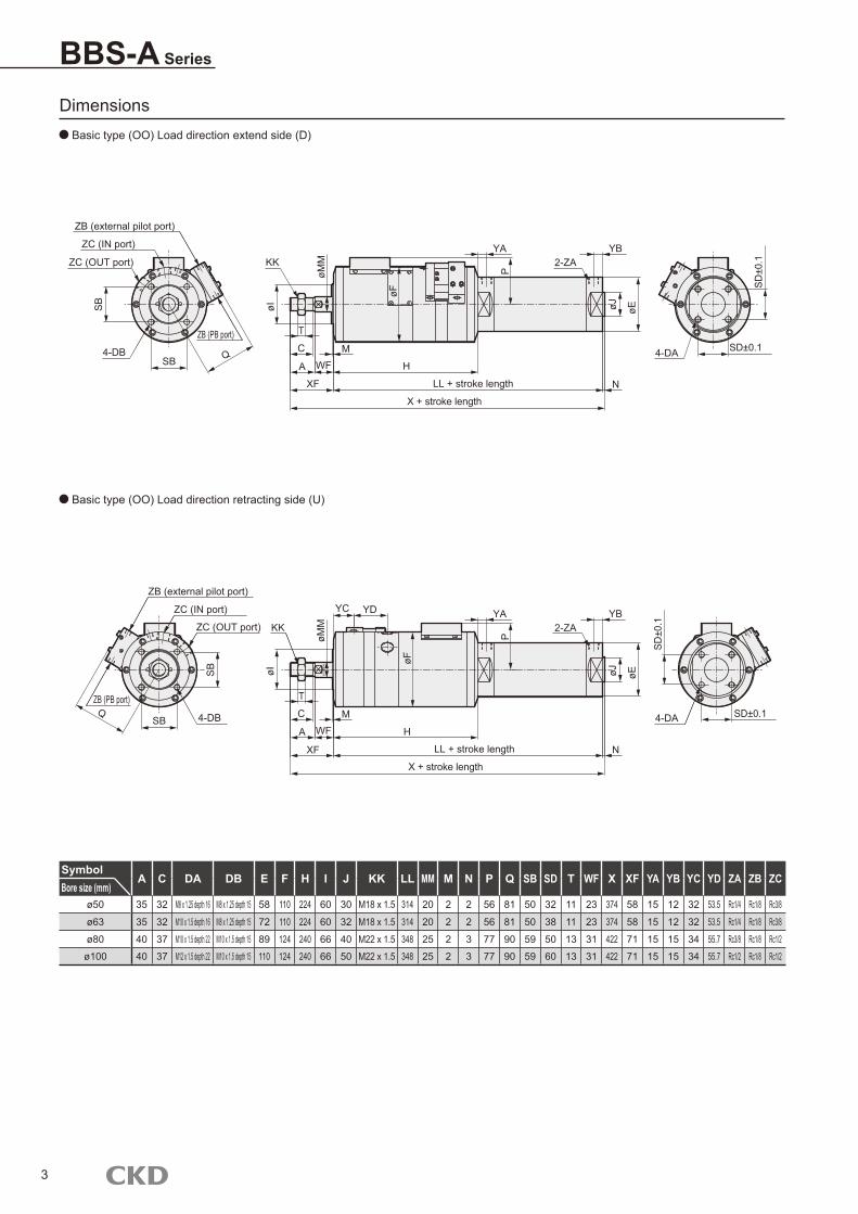
BBS-A Series
Dimensions Basic type (OO) Load direction extend side (D)
Basic type (OO) Load direction retracting side (U)
SymbolA C DA DB E F H I J KK LL MM M N P Q SB SD T WF X XF YA YB YC YD ZA ZB ZC
Bore size (mm)ø50 35 32 M8 x 1.25 depth 16 M8 x 1.25 depth 15 58 110 224 60 30 M18 x 1.5 314 20 2 2 56 81 50 32 11 23 374 58 15 12 32 53.5 Rc1/4 Rc1/8 Rc3/8
ø63 35 32 M10 x 1.5 depth 16 M8 x 1.25 depth 15 72 110 224 60 32 M18 x 1.5 314 20 2 2 56 81 50 38 11 23 374 58 15 12 32 53.5 Rc1/4 Rc1/8 Rc3/8
ø80 40 37 M10 x 1.5 depth 22 M10 x 1.5 depth 15 89 124 240 66 40 M22 x 1.5 348 25 2 3 77 90 59 50 13 31 422 71 15 15 34 55.7 Rc3/8 Rc1/8 Rc1/2
ø100 40 37 M12 x 1.5 depth 22 M10 x 1.5 depth 15 110 124 240 66 50 M22 x 1.5 348 25 2 3 77 90 59 60 13 31 422 71 15 15 34 55.7 Rc1/2 Rc1/8 Rc1/2
3
ZB (external pilot port)
ZC (IN port)
ZC (OUT port)
4-DB
ZB (PB port)
SB Q
KK
T
C
A
XF
MWF H
LL + stroke length
X + stroke length
YA YB2-ZA
N
øI
øF
P
øJ øE
4-DA
4-DBQ
ZB (external pilot port)
ZC (IN port)
ZC (OUT port)
ZB (PB port)
KK
T
C
A
XF
MWF H
LL + stroke length
X + stroke length
YA YB2-ZA
N
øI
øF
P
øJ øE
4-DA SD±0.1
YC YD
SB
SD±0.1
SB
øMM
øMM
SB
SD±0
.1
SD±0
.1
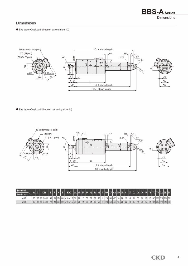
BBS-A SeriesDimensions
Dimensions Eye type (CA) Load direction extend side (D)
Eye type (CA) Load direction retracting side (U)
SymbolA C DB E F H I KK LL MM M P Q R SB T WF XF CA CD CE CI CT CJ CM CN YA YB YC YD ZA ZB ZC
Bore size (mm)ø50 35 32 M8 x 1.25 depth 15 58 110 224 60 M18 x 1.5 314 20 2 56 81 29 50 11 23 58 417 16 20 19 6 362 60 79.6 15 12 32 53.5 Rc1/4 Rc1/8 Rc3/8
ø63 35 32 M8 x 1.25 depth 15 72 110 224 60 M18 x 1.5 314 20 2 56 81 36 50 11 23 58 424 18 22 22 8 367 74 97.8 15 12 32 53.5 Rc1/4 Rc1/8 Rc3/8
4
ZB (external pilot port)
ZC (IN port)
ZC (OUT port)
4-DB ZB (PB port)
Q
KK
T
C
A
XF
MWF H
LL + stroke length
CA + stroke length
YA YB
2-ZA
øI
øF
P
CT
CM
CN
R
CT
øMM
CI
R CE
øE øCD e8
CJ + stroke length
KK
T
C
A
XF
MWF H
LL + stroke length
CA + stroke length
YA YB
2-ZA
øI
øF
P
CT
CM
CN
R
CT
øMM
CI
R CE
øE
øCD e8
YC YD
4-DBQ
ZB (external pilot port)
ZC (IN port)
ZC (OUT port)
ZB (PB port)
SB
SB
SB
SB
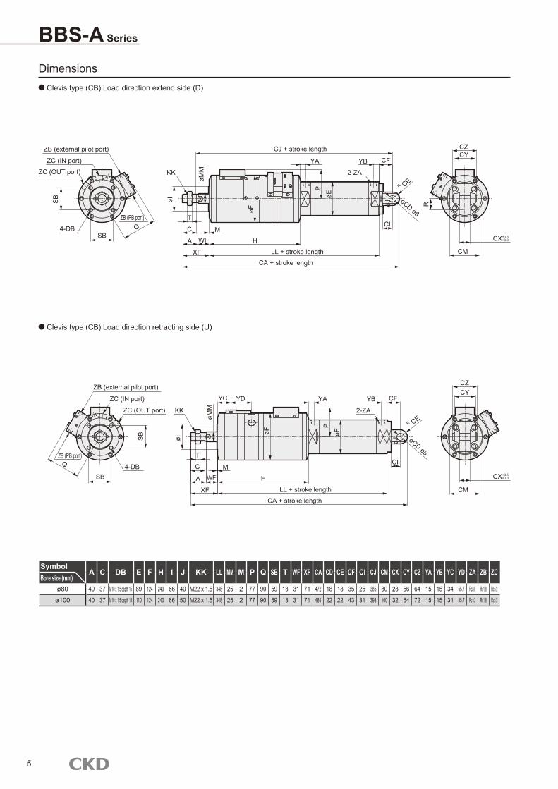
Dimensions Clevis type (CB) Load direction extend side (D)
BBS-A Series
Clevis type (CB) Load direction retracting side (U)
SymbolA C DB E F H I J KK LL MM M P Q SB T WF XF CA CD CE CF CI CJ CM CX CY CZ YA YB YC YD ZA ZB ZC
Bore size (mm)ø80 40 37 M10 x 1.5 depth 15 89 124 240 66 40 M22 x 1.5 348 25 2 77 90 59 13 31 71 472 18 18 35 25 385 80 28 56 64 15 15 34 55.7 Rc3/8 Rc1/8 Rc1/2
ø100 40 37 M10 x 1.5 depth 15 110 124 240 66 50 M22 x 1.5 348 25 2 77 90 59 13 31 71 484 22 22 43 31 393 100 32 64 72 15 15 34 55.7 Rc1/2 Rc1/8 Rc1/2
5
4-DBQ
ZB (external pilot port)
ZC (IN port)
ZC (OUT port)
ZB (PB port)
KK
T
C
A
XF
MWF H
LL + stroke length
CA + stroke length
YA YB
2-ZA
CI
øI
øF
P
øJ
øE
CM
YC YD
CZCY
øMM
CF
R CE
øCD e8
CM
CZCY
R CE
øCD e8
4-DB Q
ZB (external pilot port)
ZC (IN port)
ZC (OUT port)
ZB (PB port)
KK
T
C
A
XF
MWF H
LL + stroke length
CA + stroke length
YA YB
2-ZA
CI
øI
øF
P
øJ
øE
øMM
CF
CJ + stroke length
R
SB
SB
SB
SB
CX+0.5+0.3
CX+0.5+0.3
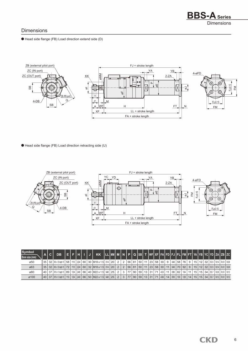
Dimensions Head side flange (FB) Load direction extend side (D)
BBS-A SeriesDimensions
Head side flange (FB) Load direction retracting side (U)
SymbolA C DB E F H I J KK LL MM M N P Q SB T WF XF FA FD FJ FL FM FT YA YB YC YD ZA ZB ZC
Bore size (mm)ø50 35 32 M8 x 1.25 depth 15 58 110 224 60 30 M18 x 1.5 314 20 2 2 56 81 50 11 23 58 383 9 346 58 76 9 15 12 32 53.5 Rc1/4 Rc1/8 Rc3/8
ø63 35 32 M8 x 1.25 depth 15 72 110 224 60 32 M18 x 1.5 314 20 2 2 56 81 50 11 23 58 383 11 346 70 92 9 15 12 32 53.5 Rc1/4 Rc1/8 Rc3/8
ø80 40 37 M10 x 1.5 depth 15 89 124 240 66 40 M22 x 1.5 348 25 2 3 77 90 59 13 31 71 433 11 390 82 104 11 15 15 34 55.7 Rc3/8 Rc1/8 Rc1/2
ø100 40 37 M10 x 1.5 depth 15 110 124 240 66 50 M22 x 1.5 348 25 2 3 77 90 59 13 31 71 436 14 393 100 128 14 15 15 34 55.7 Rc1/2 Rc1/8 Rc1/2
6
ZB (external pilot port)
ZC (IN port)
ZC (OUT port)
4-DB
ZB (PB port)Q
KK
T
C
A
XF
MWF H
LL + stroke length
FA + stroke length
YA YB2-ZA
øI
øF
P
FL±0.15
FM
4-øFD
øMM
øE
FJ + stroke length
4-DBSB
Q
ZB (external pilot port)
ZC (IN port)
ZC (OUT port)
ZB (PB port)
øJ
FT N
KK
T
C
A
XF
MWF H
LL + stroke length
FA + stroke length
YA YB
2-ZA
øI
øF
P
4-øFD
øMM
øE
FJ + stroke length
øJ
FT N
YC YD
SB
FL±0.15
FM
SB
FL±0
.15
FM
SB
FL±0
.15
FM
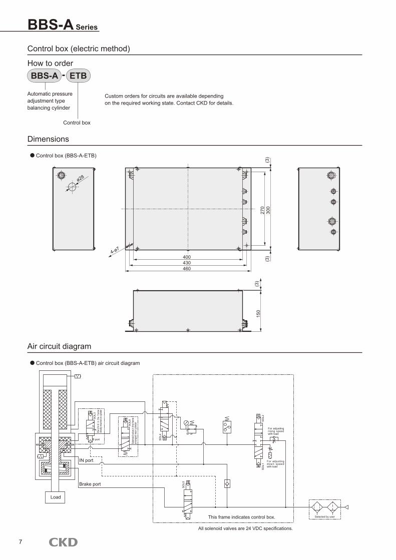
Dimensions
Air circuit diagram
BBS-A Series
Control box (electric method)
How to order
Custom orders for circuits are available depending on the required working state. Contact CKD for details.
Automatic pressure adjustment typebalancing cylinder
BBS-A
Control box
Control box (BBS-A-ETB)
Control box (BBS-A-ETB) air circuit diagram
ETB
7
ø28
4004-ø7
430460
270
300
(3)
(3)
(3)
150
SO
L3M
anifo
ld in
the
fram
e dir
ectly
mou
nted o
n cylin
der
B port
IN port
SO
L6So
lenoid
valve
in th
e fra
me
arra
nged
nea
r cyli
nder
Brake port
Load
SO
L2
For adjusting rising speed with load
SO
L1
For adjusting down speed with load
This frame indicates control box.
All solenoid valves are 24 VDC specifications.
Selected by user
SO
L4
SO
L5
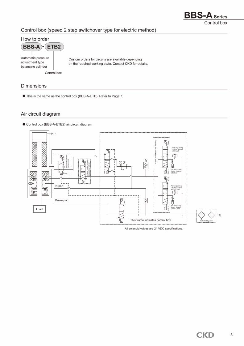
Air circuit diagram
Control box (speed 2 step switchover type for electric method)
How to order
Custom orders for circuits are available depending on the required working state. Contact CKD for details.
Automatic pressure adjustment typebalancing cylinder
BBS-A
Control box
ETB2
Control box (BBS-A-ETB2) air circuit diagram
BBS-A SeriesControl box
Dimensions
This is the same as the control box (BBS-A-ETB). Refer to Page 7.
8
SO
L5
Manifo
ld in
the fra
me di
rectly
moun
ted on
cylind
er
B port
IN port
SO
L8So
lenoid
valve
in th
e fra
me
arra
nged
nea
r cyli
nder
Brake port
Load
SO
L4
For adjusting r ising speed with load
SO
L3For adjusting down speed with load
This frame indicates control box.
All solenoid valves are 24 VDC specifications.
Selected by user
SO
L6
SO
L7
SO
L2S
OL1
For adjusting r ising speed without load
For adjusting down speed without load
Val
ves
in th
e fra
me
are
man
ifold
.
Dimensions
Air circuit diagram
BBS-A Series
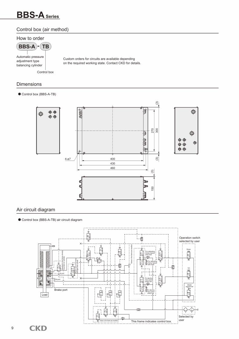
Control box (air method)
How to order
Custom orders for circuits are available depending on the required working state. Contact CKD for details.
Automatic pressure adjustment typebalancing cylinder
BBS-A
Control box
TB
Control box (BBS-A-TB)
Control box (BBS-A-TB) air circuit diagram
9
4-ø7 400430460
270
300
(3)
(3)
(3)
150
Man
ifold
in th
e fra
me
dire
ctly
m
ount
ed o
n cy
linde
r
Mas
ter v
alve
in th
e fra
me
arra
nged
nea
r cyli
nder
Load
Brake port
IN port
B port
Valves in the frame are manifold. This frame indicates control box.
For adjusting rising speed with load
For adjusting rising speed without load
Operation switch selected by user
Down
Up
Brake switchover
Selected by user
t10
For adjusting rising speed with load
t10 t10
Valve
s in
the
fram
e ar
e m
anifo
ld.
For adjusting rising speed without load
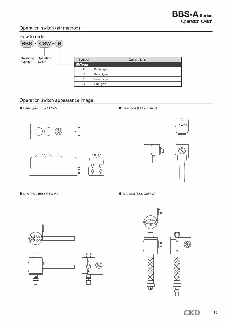
BBS-A SeriesOperation switch
Operation switch (air method)
How to order
Balancingcylinder
R
Symbol DescriptionsType
P Push typeH Hand typeR Lever typeG Grip type
A
Operation switch appearance image Push type (BBS-CSW-P) Hand type (BBS-CSW-H)
Lever type (BBS-CSW-R) Grip type (BBS-CSW-G)
BBS CSW
Operation switch
10
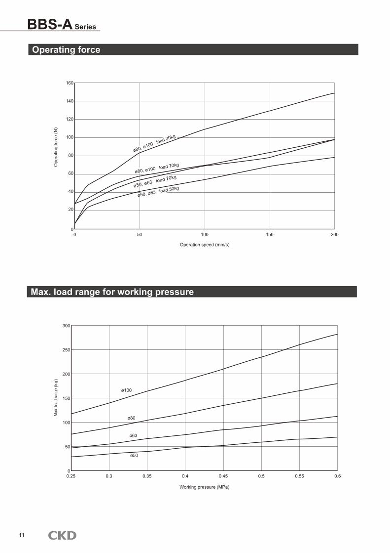
Operating force
Max. load range for working pressure
BBS-A Series
11
160
140
120
100
80
60
20
40
050 100 150 2000
Operation speed (mm/s)
Ope
ratin
g fo
rce
(N)
300
250
200
150
100
50
00.3 0.35 0.4 0.45 0.5 0.55 0.60.25
Max
. load
rang
e (k
g)
Working pressure (MPa)
ø80, ø100 load 30kg
ø80, ø100 load 70kg
ø100
ø80
ø63
ø50
ø50, ø63 load 70kg
ø50, ø63 load 30kg

12
M E M OM E M O
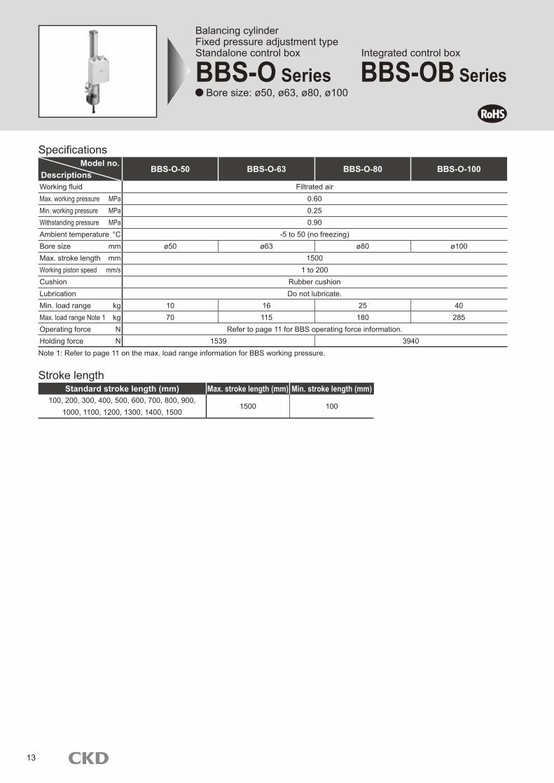
Balancing cylinderFixed pressure adjustment typeStandalone control box Integrated control box
BBS-O Series BBS-OB Series Bore size: ø50, ø63, ø80, ø100
Specifications
Note 1: Refer to page 11 on the max. load range information for BBS working pressure.
Model no.Descriptions
BBS-O-50 BBS-O-63 BBS-O-80 BBS-O-100
Working fluid Filtrated airMax. working pressure MPa 0.60Min. working pressure MPa 0.25Withstanding pressure MPa 0.90Ambient temperature °C -5 to 50 (no freezing)Bore size mm ø50 ø63 ø80 ø100Max. stroke length mm 1500Working piston speed mm/s 1 to 200Cushion Rubber cushionLubrication Do not lubricate.Min. load range kg 10 16 25 40Max. load range Note 1 kg 70 115 180 285Operating force N Refer to page 11 for BBS operating force information.Holding force N 1539 3940
Stroke lengthStandard stroke length (mm) Max. stroke length (mm) Min. stroke length (mm)
100, 200, 300, 400, 500, 600, 700, 800, 900, 1000, 1100, 1200, 1300, 1400, 1500
1500 100
13
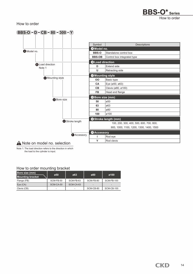
BBS-O* SeriesHow to order
Note on model no. selectionNote 1: The load direction refers to the direction in which
the load to the cylinder is input.
How to order
BBS-O
AccessoryF
Stroke lengthE
Bore sizeD
Mounting styleC
Load directionNote 1
B
Model no.A
D YCB 30080
Symbol DescriptionsModel no.
BBS-O Standalone control boxBBS-OB Control box integrated type
Load directionD Extend sideU Retracting side
Mounting styleOO Basic typeCA Eye (ø50, ø63)CB Clevis (ø80, ø100)FB Head end flange
Bore size (mm)50 ø5063 ø6380 ø80100 ø100
Stroke length (mm)100, 200, 300, 400, 500, 600, 700, 800,
900, 1000, 1100, 1200, 1300, 1400, 1500
AccessoryI Rod eyeY Rod clevis
A
B
C
D
F
E
Bore size (mm)ø50 ø63 ø80 ø100
Mounting bracketFlange (FB) SCM-FB-50 SCM-FB-63 SCM-FB-80 SCM-FB-100
Eye (CA) SCM-CA-50 SCM-CA-63 - -
Clevis (CB) - - SCM-CB-80 SCM-CB-100
How to order mounting bracket
14
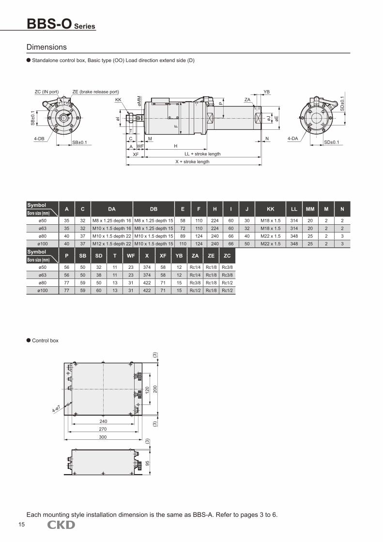
BBS-O Series
Dimensions Standalone control box, Basic type (OO) Load direction extend side (D)
Control box
Each mounting style installation dimension is the same as BBS-A. Refer to pages 3 to 6.
SymbolA C DA DB E F H I J KK LL MM M N
Bore size (mm)ø50 35 32 M8 x 1.25 depth 16 M8 x 1.25 depth 15 58 110 224 60 30 M18 x 1.5 314 20 2 2
ø63 35 32 M10 x 1.5 depth 16 M8 x 1.25 depth 15 72 110 224 60 32 M18 x 1.5 314 20 2 2
ø80 40 37 M10 x 1.5 depth 22 M10 x 1.5 depth 15 89 124 240 66 40 M22 x 1.5 348 25 2 3
ø100 40 37 M12 x 1.5 depth 22 M10 x 1.5 depth 15 110 124 240 66 50 M22 x 1.5 348 25 2 3
SymbolP SB SD T WF X XF YB ZA ZE ZC
Bore size (mm)ø50 56 50 32 11 23 374 58 12 Rc1/4 Rc1/8 Rc3/8
ø63 56 50 38 11 23 374 58 12 Rc1/4 Rc1/8 Rc3/8
ø80 77 59 50 13 31 422 71 15 Rc3/8 Rc1/8 Rc1/2
ø100 77 59 60 13 31 422 71 15 Rc1/2 Rc1/8 Rc1/2
15
ZC (IN port)
4-DBSB±0.1
KK
T
C
A
XF
MWF H
LL + stroke length
X + stroke length
YB
ZA
N
øI
øMM
P
øJ øE
4-DASD±0.1
ZE (brake release port)
240
270
300
4-ø7
(3)
120
200
95(3
)
(3)
SB
±0.1
F
SD
±0.1
Each mounting style installation dimension is same as BBS-A. Refer to pages 3 to 6.
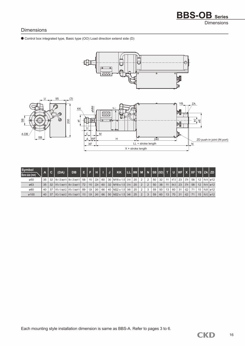
BBS-OB SeriesDimensions
Dimensions Control box integrated type, Basic type (OO) Load direction extend side (D)
SymbolA C (DA) DB E F H I J KK LL MM M N SB (SD) T U WF X XF YB ZA ZD
Bore size (mm)ø50 35 32 M8 x 1.25 depth 16 M8 x 1.25 depth 15 58 110 224 60 30 M18 x 1.5 314 20 2 2 50 32 11 47.5 23 374 58 12 Rc1/4 ø12
ø63 35 32 M10 x 1.5 depth 16 M8 x 1.25 depth 15 72 110 224 60 32 M18 x 1.5 314 20 2 2 50 38 11 54.5 23 374 58 12 Rc1/4 ø12
ø80 40 37 M10 x 1.5 depth 22 M10 x 1.5 depth 15 89 124 240 66 40 M22 x 1.5 348 25 2 3 59 50 13 60 31 422 71 15 Rc3/8 ø12
ø100 40 37 M12 x 1.5 depth 22 M10 x 1.5 depth 15 110 124 240 66 50 M22 x 1.5 348 25 2 3 59 60 13 70 31 422 71 15 Rc1/2 ø12
16
4-DBSB
KK
T
C
A
XF
MWF H
LL + stroke length
X + stroke length
YB ZA
øI
øMM
øJ øE
NZD push-in joint (IN port)
U 95 (3)
200
240
F
SB
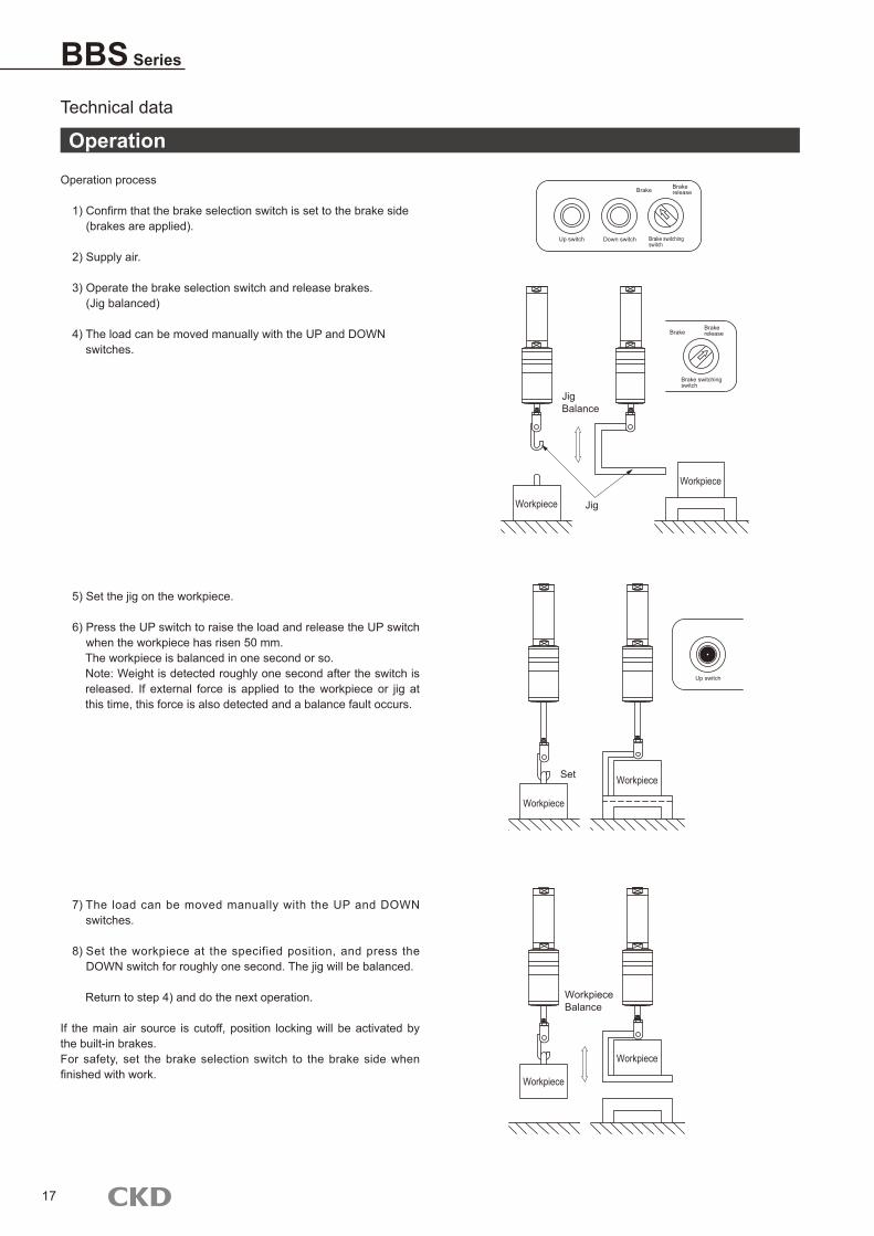
BBS Series
Technical data
Operation process
1) Confirm that the brake selection switch is set to the brake side (brakes are applied).
2) Supply air.
3) Operate the brake selection switch and release brakes. (Jig balanced)
4) The load can be moved manually with the UP and DOWN switches.
5) Set the jig on the workpiece.
6) Press the UP switch to raise the load and release the UP switch when the workpiece has risen 50 mm. The workpiece is balanced in one second or so. Note: Weight is detected roughly one second after the switch is released. If external force is applied to the workpiece or jig at this time, this force is also detected and a balance fault occurs.
7) The load can be moved manually with the UP and DOWN switches.
8) Set the workpiece at the specified position, and press the DOWN switch for roughly one second. The jig will be balanced.
Return to step 4) and do the next operation.
If the main air source is cutoff, position locking will be activated by the built-in brakes. For safety, set the brake selection switch to the brake side when finished with work.
Operation
17
Up switch Down switch Brake switching switch
Brake Brake release
BrakeBrake release
Brake switching switch
JigBalance
JigWorkpiece
Workpiece
Up switch
Workpiece
Workpiece
Set
Workpiece
Workpiece
WorkpieceBalance
BBS SeriesTechnical data
Technical data
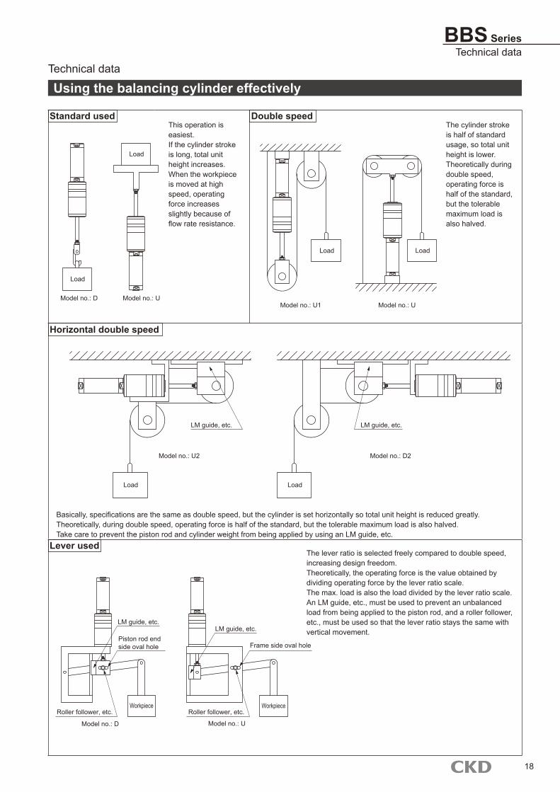
Standard usedThis operation is easiest. If the cylinder stroke is long, total unit height increases. When the workpiece is moved at high speed, operating force increases slightly because of flow rate resistance.
Double speedThe cylinder stroke is half of standard usage, so total unit height is lower. Theoretically during double speed, operating force is half of the standard, but the tolerable maximum load is also halved.
Basically, specifications are the same as double speed, but the cylinder is set horizontally so total unit height is reduced greatly. Theoretically, during double speed, operating force is half of the standard, but the tolerable maximum load is also halved. Take care to prevent the piston rod and cylinder weight from being applied by using an LM guide, etc.
Lever usedThe lever ratio is selected freely compared to double speed, increasing design freedom. Theoretically, the operating force is the value obtained by dividing operating force by the lever ratio scale. The max. load is also the load divided by the lever ratio scale. An LM guide, etc., must be used to prevent an unbalanced load from being applied to the piston rod, and a roller follower, etc., must be used so that the lever ratio stays the same with vertical movement.
Using the balancing cylinder effectively
Horizontal double speed
18
Load
Model no.: D Model no.: U
Load
Load
Model no.: U1 Model no.: U
Load
LM guide, etc.
Model no.: U2
Load Load
Model no.: D2
LM guide, etc.
LM guide, etc.
Piston rod end side oval hole
Roller follower, etc.
Model no.: D
Workpiece WorkpieceRoller follower, etc.
Model no.: U
LM guide, etc.
Frame side oval hole

19
M E M OM E M O

20
M E M OM E M O

2008.9.ACC


![Tread lightly caravan photos [autosaved]](https://img.pdfslide.net/doc/110x75/58f30ab91a28ab94158b4605/tread-lightly-caravan-photos-autosaved.jpg)

