Embed Size (px)
Citation preview
International Journal of Plasticity, Vol. 9, pp. 603-618, 1993 0749-6419/93 $6.00 + .00 Printed in the USA Copyright © 1993 Pergamon Press Ltd.
L I M I T S T R A I N P R E D I C T I O N S F O R O U T - O F - P L A N E S T R E T C H I N G O F S H E E T M E T A L S
A. ZEGHLOUL and G. FERRON
Universit~ de Metz
Abs t rac t -An investigation is performed to predict the limits to sheet metal stretchability in dif- ferent out-of-plane experiments. Based on the time-independent flow theory, the analysis includes the effects of strain hardening and normal anisotropy and utilizes different yield functions with the assumption of isotropic hardening. The limit strains, determined either from the condition of bifurcation at maximum pressure for hydrostatic bulging, or from the analysis of flow local- ization in hemispherical punch stretching, depend on the type of the test. For a given test, how- ever, the plot of the limit strains in the usual et - e2 diagram does not exhibit a marked sensitivity to the yield function utilized. This behaviour contrasts with the predictions of insta- bility models assuming in-plane stretching.
1. INTRODUCTION
Sheet metal ductility is limited in stamping operations by various plastic instabilities. In particular, localized necking may occur in the case of biaxial tensile loading in the sheet. The situation, however, is different in the two cases of either drawing (e2 < 0) or stretching (e2 > 0) in the direction of minor principal strain e2. Drawing in some "cir- cumferential" direction is expected in regions surrounding a punch, where the metal is forced "inward" by the punch. The limiting case of plane-strain stretching (e2 = 0) is observed in the side wall of a stamping. In these circumstances the curvature of the sheet either is small or does not evolve significantly during the sequence of interest. In con- trast, biaxial stretching occurs in regions where ribs, domes, or embossments are formed at the contact of a punch. The curvature of the sheet increases during stamping, and a state of biaxial tensile stresses develops in the sheet. These stresses are in equilibrium with the normal and tangential (frictional) forces, with a degree of biaxiality that depends on the local values of the principal curvatures of the tool, and on the stiffness of the surrounding parts.
In relation to these drastic differences in geometry, it is worth recalling that the bifur- cation analysis proposed by HILL [1952] for in-plane loading of rigid-plastic sheet mate- rials obeying the flow theory predicts forming li/nits (generally in good agreement with experiments) only for negative e2-values. In comparison with this simple and convinc- ing explanation, localized necking for in-plane biaxial stretching is far from being dearly understood. The maximum load criterion proposed by Swwr [1952] is relevant to a mode of diffuse instability, and is thus not expected to manifest in the form of a local neck- ing band, as experimentally observed. Moreover, Swan's [1952] criterion does not apply to radial strain paths (HinT [1991]), and it will therefore be left out of consideration in this paper. With the flow theory, and in the absence of a pointed vertex on the yield sur- face, forming limits for e2 > 0 can be predicted at this time only by postulating the exis- tence of initial defects in the sheet (MARclNIAK & KUCZYNSKI [1967]) or by making use of a perturbation analysis for studying the rate of growth of instabilities (DuDzINSKI &
603
604 A. ZEGHLOULand G. FERRON
MOLINARI [1991]). In these treatments, the initial size of the defect and the critical rate of growth of the fastest unstable mode are adjustable parameters, which are chosen with- out obvious reference to physical considerations. Moreover, the shape of the yield locus has a strong influence on the calculated limit strains (PAR~,R & MELLOR [1978]; TVER- GAARD [1978]; NEALE & CHATER [1980]; FERRON & MLIHA-TOUATI [1985]; LIAN et al.
[1989]; ZEGHLOUL et al. [1990]). This influence, as manifested for instance by the desta- bilizing effect of large values of the normal anisotropy coefficient R in HILL's [1948] qua- dratic yield function, has no clear bearings with experimental observations.
It appears in this context that more attention should be given to the analysis of plas- tic instability under conditions of out-of-plane biaxial stretching. A particular situation of interest corresponds to the plastic bulging of a sheet clamped along an elliptical con- tour and loaded by lateral hydrostatic pressure. The bifurcation mode, at least for not too small ratios of minor to major axes of the ellipse, corresponds to the development of a local neck spreading from the pole along the direction of the major axis (ISEKI et al. [1977]). Another test representative of biaxial stretching conditions is the hemi- spherical punch test. The analysis of this test is particularly recommended since the form- ing limits in the biaxial stretching range are frequently determined by this procedure. In this experiment a peak in radial strain distribution develops during the punch travel, leading to localized necking and failure along some intermediate circumferential direc- tion in the region of punch contact (KEELER & BACKOFEN [1963] ; WANG [ 1970]; GHOSH & HECKER [1975]; WANG & BUDIANSKY [1978]; KNIBLOE & WAGONER [1989]).
In this paper the instability strains are analysed in a number of experimental situa- tions. The conditions of instability in pressurized thin-walled cylinders and spherical shells are briefly recalled first to emphasize the prominent part played by the evolution of membrane curvature during loading. The condition of maximum pressure is then investigated for hydrostatic bulging, in the two limiting cases of a long strip clamped at its two edges and of a circular membrane, both loaded by lateral hydrostatic pres- sure. A straightforward analytical solution is obtained for the plane-strain stretching of a long strip. An FDM program (ZEGHLOUL et al. [1991]), which allows a flexible account of transversely isotropic material behaviour, is utilized for the circular mem- brane. The ABAQUS FEM code is finally used to investigate plastic flow localization in the hemispherical punch test.
All calculations are carried out in the framework of time-independent flow theory of plasticity with the assumption of isotropic hardening. The effects of strain hardening and yield locus shape are examined. At variance with the results obtained with a defect approach or a perturbation approach to in-plane stretching limits, which only concen- trate on the effect of material parameters, it is shown that the boundary conditions of the process play an important part in the attainable limit strains.
11. INSTABILITY STRAINS IN PRESSURIZED THIN-WALLED SHELLS
For the purpose of comparison with sheet metal stretching, it is worth recalling the results obtained for a thin-walled tube with closed ends under combined internal pres- sure p and external tensile load P, and for a thin-walled spherical shell under internal pressure p. The conditions of instability for the tube have been set up by MELLOR [1962] and re-examined by HILL [1991]. The derivations recalled below apply for orthotropic materials with the principal axes of orthotropy along the axial, hoop, and normal direc-
Out-of-plane stretchability of sheet metals 605
tions. In the absence of instability the solution corresponds to a homogeneous state of membrane stresses,
01 = p p / h (1)
and
02 = ( P + 7rp2p) /2rah, (2)
where 01 and 02 are the hoop and axial Cauchy stresses, respectively, a is the current mean radius, and h is the current thickness. Under constant stress-ratio conditions (i.e. with P/Tr pEp = constant, d01/0~ = d02/02 = d # / 6 and de l / e l = de2/e2 = dg/~) and assuming a power-type stress-strain law 6 = Kg N (where 6 and g are the effective stress and strain, respectively, K is the strength coefficient, and N is the work-hardening expo- nent) the conditions of instability, associated with the simultaneous stationarity of either p and P/Trp 2, or P and "lrp2p, can be expressed, with dp/p = del and d h / h = - ( d e ~ + dc2) resulting from the condition of plastic incompressibility, in the following form:
2el "~'E2 = N (3)
and
e 2 = N , (4)
where el and e 2 are the logarithmic hoop and axial strains, respectively. The condition of maximum pressure, eqn (3), is reached first when p is increasing, i.e. when the hoop strain el is positive. Inversely, the condition of maximum external load, eqn (4), is attained first when el is negative. Similar calculations for a pressurized thin-walled spherical shell (with possible normal anisotropy) yield, with ol = 02 = p p / 2 h , dp /p = del = de2 and d h / h = - 2 d e 1 ,
N el = e 2 = ~ - . (5)
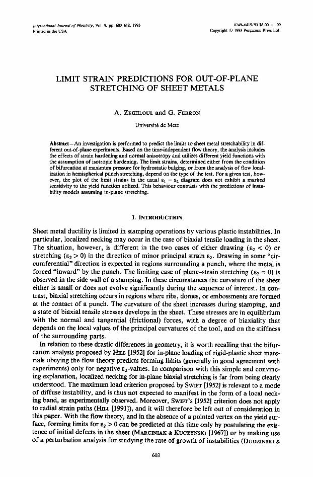
These results are summarized on Fig. 1. According to experiments by JONES and MEL- LOR [1967], instability for tubes corresponds to the formation of a bulge along the tube for stress-states between equi-biaxial tension and pure hoop tension, and of a neck along the tube for pure axial tension. Instability then presents a diffuse character, and CON- SIDERE's criterion actually is retrieved in pure axial tension (el = - N / 2 ; e2 = N on Fig. 1). The situation is different under plane-strain axial tension. In that case the com- bined effects of loading and geometry lead to the formation of a local neck along the circumferential direction, without any evidence for previous diffuse necking. Since the radius of the tube is kept constant during loading, the situation actually is much the same as that of a sheet under plane-strain tension, and HILL'S [1952] condition for localized necking is retrieved (el = 0; e2 = N on Fig. 2), with the neck aligned along the direc- tion of zero extension.
It clearly appears that these limit strains are much lower than those observed in sheet- metal forming, except near to the point of plane-strain tension in the axial direction of
606 A. ZEGHLOUL and G. FERRON
z
1.5
0.5
-0.5
-1
x~, , ,
\ - / : .
~ EBT /
AT :axial tension(tube) ~ APST \ \ \
HT hoop tenslon(tube) ~ AT \ \ \
• APST:axial plane-strain tension(tube) ~ ' ~
HPST:hoop plane-strain tension(tube)
EBT :equibiaxial tension(tube and spherical shell) I I I I
-I -0.5 0 0.5 1 1,5
Fig. 1. Instability strains in thin-walled tubes and spherical shells (full line). A typical forming limit diagram for sheet metals (dashed line) is shown for comparison.
the tube. As discussed below, the drastic differences observed in the stretching range between limit strains for tubes (or shells), and sheets should be ascribed to structure effects (i.e. the destabilizing effect of the increase in the radius of pressurized tubes or shells, as compared to the stabilizing effect of the increase in membrane curvature expe- rienced during out-of-plane biaxial stretching of thin sheets).
II!. INSTABILITY STRAINS IN PRESSURIZED THIN SHEETS
In the case of a thin sheet clamped along a circular contour and loaded by lateral hydrostatic pressure, a localized neck spreading from the pole is experimentally observed at maximum pressure (IsEKI et al. [1977]). Similarly, for a long strip clamped at its two edges and loaded by lateral hydrostatic pressure, through-thickness thinning parallel to the clamped edges is consistently expected at maximum pressure. The situation is not so clear in the intermediate case of elliptical contours, where a neck spreading from the pole along the direction of the major axis forms under increasing pressure (ISErd et al. [1977]). The condition of maximum pressure is thus investigated in the two limiting cases of a long strip and a circular membrane. In view of the inefficiency of SWr~T'S [1952] maximum load criterion to account for localized necking, the predictions derived from the condition of maximum pressure will be compared, in the case of the long strip, with HILL'S [1952] condition for localized necking under in-plane plane-strain stretching, and, for the circular membrane, with the results obtained from a local defect model.
Out-of-plane stretchability of sheet metals 607
III. 1. Plane-strain plastic bulging o f a long strip
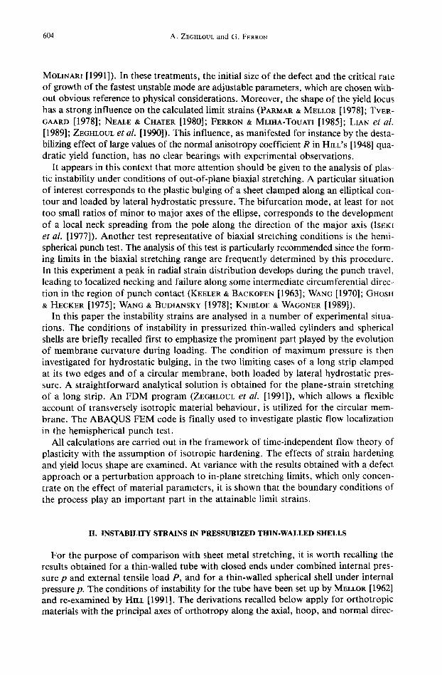
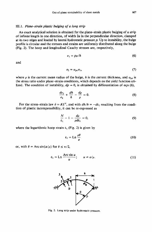
An exact analytical solution is obtained for the plane-strain plastic bulging of a strip of infinite length in one direction, of width 2a in the perpendicular direction, clamped at its two edges and loaded by lateral hydrostatic pressure p. Up to instability, the bulge profile is circular and the stresses and strains are uniformly distributed along the bulge (Fig. 2). The hoop and longitudinal Cauchy stresses are, respectively,
and
(71 = po /h (6)
(72 -~ Olps (71, (7)
where o is the current mean radius of the bulge, h is the current thickness, and Ups is the stress ratio under plane-strain conditions, which depends on the yield function uti- lized. The condition of instability, dp = 0, is obtained by differentiation of eqn (6),
d(7__!l + dh do _ O. (8) (71 h O
For the stress-strain law 6 = Kg N, and with dh/h = - d e 1 resulting from the condi- tion of plastic incompressibility, it can be re-expressed as
N do - - - 1 - 0 , ( 9 ) e I ode1
where the logarithmic hoop strain el (Fig. 2) is given by
el = Ln 00 ( 1 0 ) a
or, with 0 = Arc sin(a/o) for 0 _< ~r/2,
Arc sin u el = Ln - - ;
U u = a/o. (11)
3 ~ _ 1 '< a ~-;
Y Fig. 2. Long strip under hydrostatic pressure.
608 A. ZEGHLOUL and G. FERRON
By differentiation of eqn (11) the instability condition (9) can be written in the form of the nonlinear equation for u,
I N _ll I u _11+1:o. Ln (Arc sin u/u) (Arc sin u) ~ - u 2 (12)
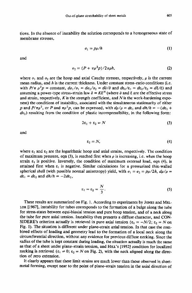
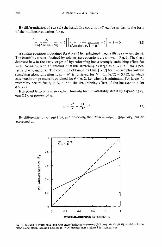
A similar equation is obtained for 0 > ~r/2 by replacing 0 in eqn (10) by (~r - Arc sin u). The instability strains obtained by solving these equations are shown in Fig. 3. The sharp decrease in p in the early stages of hydroforming has a strongly stabilizing effect for small N-values, with an amount of stable stretching as large as el = 0.238 for a per- fectly plastic material. The condition obtained by HILL [1952] for in-place plane-strain stretching along direction 1, ~1 = N, is retrieved for N = Ln(Tr/2) = 0.452, in which case maximum pressure is obtained for 0 = 7r/2, i.e. when p is minimum. For larger N, instability occurs for ej < N, due to the destabilizing effect of the increase in p for {9 > rr/2.
It is possible to obtain an explicit formula for the instability strain by expanding et, eqn (11), in powers of u,
u 2 11 ~J = -ff + 1-~ u4" (13)
By differentiation of eqn (13), and observing that du/u = - d o / o , ((do/odel) can be expressed as
z
[-.
=
b.
z
0.8
0.6
0.4
0.2
i l ' ' | ' ' i ' t ~ .
- - - N / :
( 3 = K E / ' J
/ J s /
/ t
J J
J ~ s"s'¢
pj~'J
p o" J I J
, I ! I , I
0 0.2 0.4 0.6 0.8
WORK-HARDENING EXPONENT N
Fig. 3. Instability strains in a long strip under hydrostatic pressure (full line). HILL'S [1952] condition for in- plane plane-strain localized necking (el = N, dashed line) is plotted for comparison.
Out-of-plane stretchability of sheet metals 609
do 1 11 - - = - - - + - - . ( 1 4 ) pdE 1 2el 10
The instability condition (9) finally yields
el ~ 2~ (1 + 2N) .~ 0.238(1 + 2N). (15)
The error with this expression is less than 0.5% in the whole range 0 _< N_< 1, as com- pared to the results obtained by solving eqn (12), or its mate for 0 > 7r/2 ( N > Ln(Tr/2)).
111.2. Plastic bulging o f a circular membrane
The plastic bulging of a circular membrane clamped at its edge was analysed in a pre- vious paper (Z~.GI-n, otrz et al. [1991]) by using a flexible description of yielding proposed by BtrOIANSKY [1984]. In this formulation the plane-stress yield locus of transversely isotropic materials is described parametrically by the polar coordinate form
0"1 + 0"2 - - g ( ~ ) C O S ~ ; 0"1 - - 0.2 = g(~b)sin~b, (16) 20b 2as
where (71 and 02 are the principal stresses, g(~b) is the length of the radius to a point on the normalized yield locus, and ~b is the associated polar angle. The normalizing param- eters as and as are the current yield stresses in equibiaxial tension and pure shear, respectively, so that g(0) = g(+~r/2) = 1.
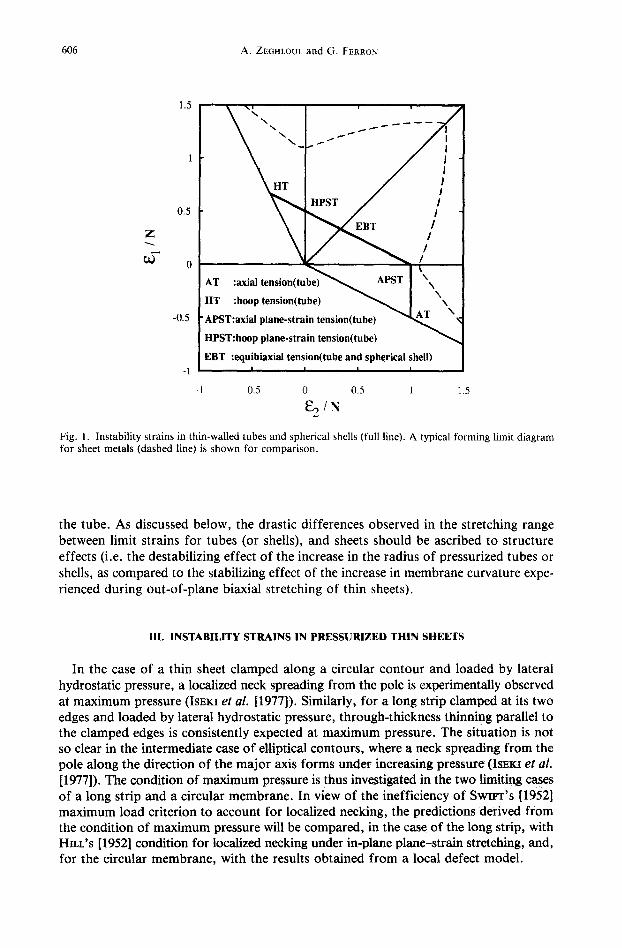
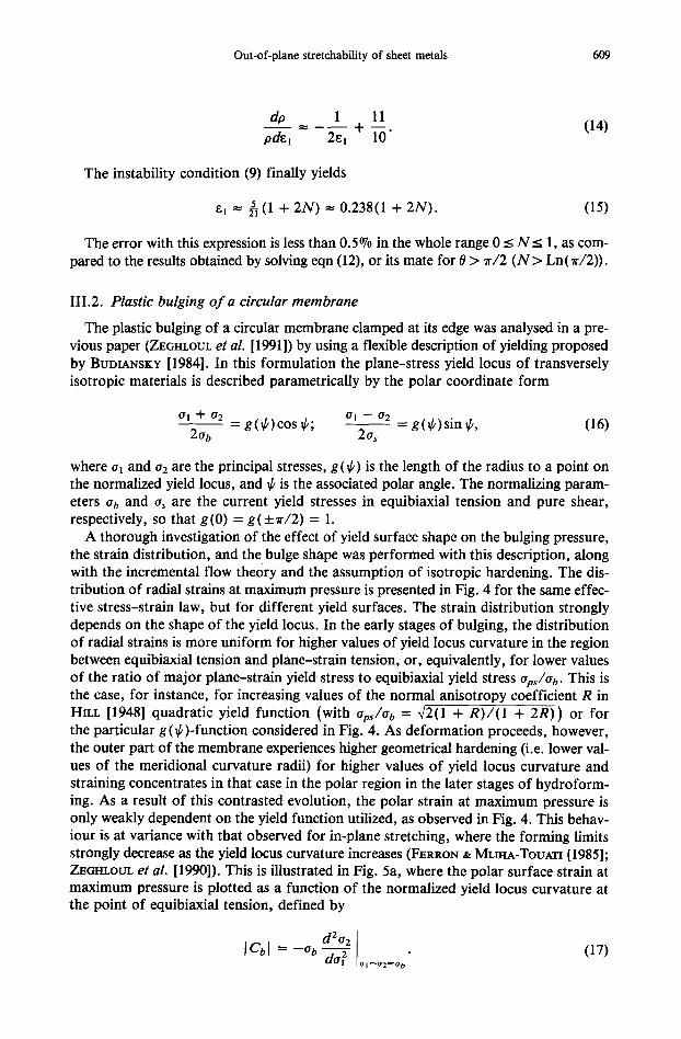
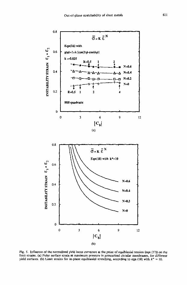
A thorough investigation of the effect of yield surface shape on the bulging pressure, the strain distribution, and the bulge shape was performed with this description, along with the incremental flow theory and the assumption of isotropic hardening. The dis- tribution of radial strains at maximum pressure is presented in Fig. 4 for the same effec- tive stress-strain law, but for different yield surfaces. The strain distribution strongly depends on the shape of the yield locus. In the early stages of bulging, the distribution of radial strains is more uniform for higher values of yield locus curvature in the region between equibiaxial tension and plane-strain tension, or, equivalently, for lower values of the ratio of major plane-strain yield stress to equibiaxial yield stress aps/ab. This is the case, for instance, for increasing values of the normal anisotropy coefficient R in HILL [1948] quadratic yield function (with Ops/Ob = 42(1 + R)/ (1 + 2R)) or for the particular g (~b)-function considered in Fig. 4. As deformation proceeds, however, the outer part of the membrane experiences higher geometrical hardening (i.e. lower val- ues of the meridional curvature radii) for higher values of yield locus curvature and straining concentrates in that case in the polar region in the later stages of hydroform- ing. As a result of this contrasted evolution, the polar strain at maximum pressure is only weakly dependent on the yield function utilized, as observed in Fig. 4. This behav- iour is at variance with that observed for in-plane stretching, where the forming limits strongly decrease as the yield locus curvature increases (FERRON & MLIHA-TouATI [1985]; ZEGrILOtrL et al. [1990]). This is illustrated in Fig. 5a, where the polar surface strain at maximum pressure is plotted as a function of the normalized yield locus curvature at the point of equibiaxial tension, defined by
d2°2 °l~°2=Ob I = (17)
610 A. ZEGttLOUL and G. FERRON
0.5
z
0.25
J
-. Hill quadratic
N = 0.2 . . . . Eqn(16) with
g(~)=l+k [¢os(2~-eos(6/g) ]
R=I ; k =-0.025
R =0.5
R=4 ~ ~ ~ ~ R4 R I
0 0.5
NORMALIZED ORIGINAL DISTANCE FROM POLE
Fig. 4. Distribution of radial strain e~ at instability in pressurized circular membranes. The curves are drawn for different yield surfaces.
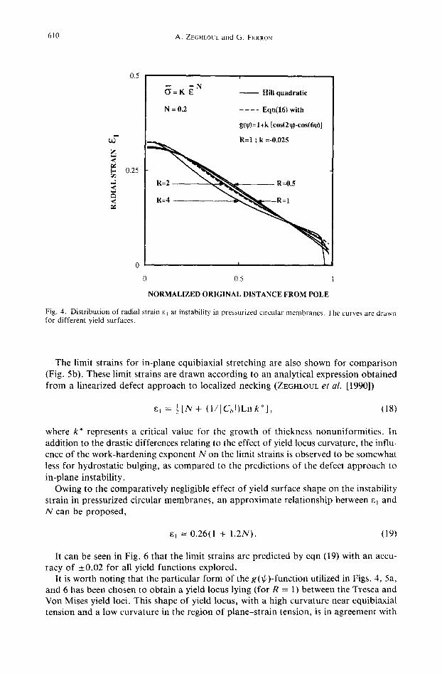
The limit strains for in-plane equibiaxial stretching are also shown for comparison (Fig. 5b). These limit strains are drawn according to an analytical expression obtained from a linearized defect approach to localized necking (ZE~nLOUL et al. [1990])
s, = ½ [ N + (1 / IC, , t )Lnk*] , (18)
where k* represents a critical value for the growth of thickness nonuniformities. In addition to the drastic differences relating to the effect of yield locus curvature, the influ- ence of the work-hardening exponent N on the limit strains is observed to be somewhat less for hydrostatic bulging, as compared to the predictions of the defect approach to in-plane instability.
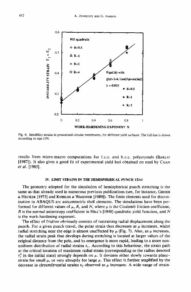
Owing to the comparatively negligible effect of yield surface shape on the instability strain in pressurized circular membranes, an approximate relationship between aj and N can be proposed,
g~ ~- 0.26(1 + 1.2N). (19)
It can be seen in Fig. 6 that the limit strains are predicted by eqn (19) with an accu- racy of _+0.02 for all yield functions explored.
It is worth noting that the particular form of the g(~/)-function utilized in Figs. 4, 5a, and 6 has been chosen to obtain a yield locus lying (for R = 1) between the Tresca and Von Mises yield loci. This shape of yield locus, with a high curvature near equibiaxial tension and a low curvature in the region of plane-strain tension, is in agreement with
Out-of-plane stretchability of sheet metals 611
0.8
0.6
0.4
0.2
0
0
0.8
~0~ 0.6 I !
z
0.4
0.2
0
t i i
Eqn(16) with
g(~/)=l+k [cos(2~-cos(6~)]
k =-0.025 R=0.5 1 2
~A ""A--- ' -A--A-- A ~ A ~ A N----0.4
- 0 - - ' 0 ~ 0 - 0 - - 0 ~ ~ 0 N---0.2
R=0.5 1 2 4
Hill quadratic
| i |
3 6 9
ICbl (a)
12
¢ , q
II
z .¢
z
i
~ = K E N
Eqn(18) with k*=10
N=0.6
N---0.4
N--0.2
N--0
0 3 6 9
I%1 (h)
12
Fig. 5. Influence of the normalized yield locus curvature at the point of equibiaxial tension (eqn (17)) on the limit strains. (a) Polar surface strain at maximum pressure in pressurized circular membranes, for different yield surfaces. (b) Limit strains for in-plane equibiaxial stretching, according to eqn (18) with k* = 10.
612 A. ZEGHLOUL and G. FERRON
0.6
t'-q
0.5 II
J z <
[.-, 0.4 rack
~ 0.3 z
0.2
0
Hill quadratic
+ R=0.5 ~ /
R=2 ~ , ~
O R=4 ~ / Eqn(16) with
g g(v)=l+k [cos(2@-cos(6~
k =-0.02S ÷ R = 0 / * R:I.S
• R=2
I I I I
0,2 0.4 0.6 0.8
WORK-HARDENING EXPONENT N
Fig. 6, Instability strains in pressurized circular membranes, for different yield surfaces. The full line is drawn according to eqn (19).
results from micro-macro computations for f.c.c, and b.c.c, polycrystals (BARLAT
[1987]). It also gives a good fit of experimental yield loci obtained on steel by CHAN et al. [1985].
IV. LIMIT STRAINS IN THE HEMISPHERICAL PUNCH TEST
The geometry adopted for the simulation of hemispherical punch stretching is the same as that already used in numerous previous publications (see, for instance, GHOSH & HECKER [1975] and KNmLOE & WAC, ONER [19899. The finite elements used for discret- ization in ABAQUS are axisymmetric shell elements. The simulations have been per- formed for different values of/~, R, and N, where/z is the Coulomb friction coefficient, R is the normal anisotropy coefficient in HILL'S [1948] quadratic yield function, and N is the work-hardening exponent.
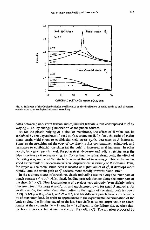
The effect of friction obviously consists of restraining radial displacement along the punch. For a given punch travel, the polar strain thus decreases as/z increases, whilst radial stretching near the edge is almost unaffected by/z (Fig. 7). Also, as/~ increases, the radial strain peak that develops during stretching is located at larger values of the original distance from the pole, and its emergence is more rapid, leading to a more non- uniform distribution of radial strains el. According to this behaviour, the strain path at the critical location of maximum radial strain (corresponding to the radius denoted r ° in the initial state) strongly depends on/~. It deviates either slowly towards plane- strain for small #, or very abruptly for large/z. This effect is further amplified by the decrease in circumferential strains a 2 observed as ~ increases. A wide range of strain-
Out-of-plane stretchability of sheet metals 613
0.6
0.4
0.2
C ~
| | i |
R=I H=28.Smm Radial strain E 1
N--0.2
i.t---0.2
Circumferential strain E 2 ~=0
0.2
0 i i i i
0 10 20 30 40 50
ORIGINAL DISTANCE FROM POLE (mm)
Fig. 7. Influence of the Coulomb friction coefficient t~ on the distribution of radial strain el and circumfer- ential strain ez in hemispherical punch stretching.
paths between plane-strain tension and equibiaxial tension is thus encompassed at r ° by varying #, i.e. by changing lubrication at the punch contact.
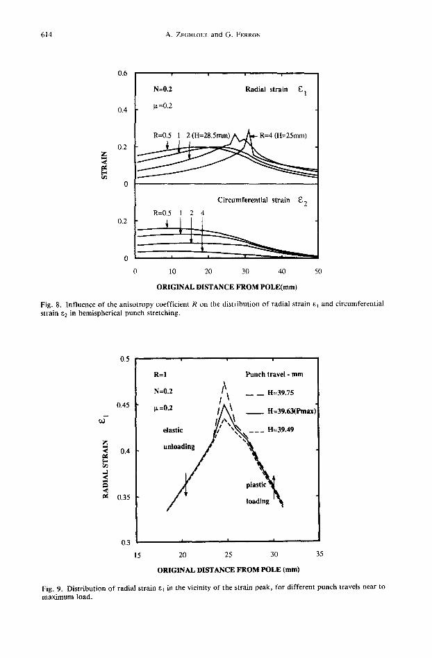
As for the plastic bulging of a circular membrane, the effect of R-value can be explained by the dependence of yield surface shape on R. In fact, the ratio of major plane-strain yield stress to equibiaxial yield stress aps/ab decreases as R increases. Plane-strain stretching (at the edge of the sheet) is thus comparatively enhanced, and resistance to equibiaxial stretching (at the pole) is increased as R increases. In other words, for a given punch travel, the polar strain decreases and radial stretching near the edge increases as R increases (Fig. 8). Concerning the radial strain peak, the effect of increasing R is, on the whole, much the same as that of increasing ~. This can be under- stood as the result of the decrease in radial displacement as either # or R increases. Thus, for larger R, the radial strain peak is located at higher values of r °, it develops more rapidly, and the strain path at r ° deviates more rapidly towards plane-strain.
In the ultimate stages of stretching, elastic unloading occurs along the inner part of punch contact (r ° < r °) whilst plastic loading proceeds further along the outer part of the sheet (r ° > r°) . Flow localization at re ° develops very abruptly (even slightly before maximum load) for large R and/or #, and much more slowly for small R and/or ~. As an illustration, the radial strain distribution in the region of the strain peak is shown in Fig. 9 for ~ = 0.2, R = 1, and N = 0.2, and for different punch travels in the vicin- ity of maximum load. In order to approximate to the experimental determination of the limit strains, the limiting radial strain has been defined as the larger value of radial strains at the two nodes (n - 1) and (n + 1) adjacent to the failure site, n, when duc- tile fracture is expected at node n (i.e., at the radius i"°). The criterion proposed by
614 A. ZEGHLOUt, and G. FERRON
0.6
0.4
0.2 z <
0
N=0.2 Radial strain E 1
~t =0.2
Circumferential strain g2
R=0.5 1 2 4 0 . 2 _ - -
0 I I , I,
0 10 20 30 40 50
ORIGINAL DISTANCE FROM POLE(mm)
Fig. 8. Influence of the anisotropy coefficient R on the distribution of radial strain E~ and circumferential strain e2 in hemispherical punch stretching.
J
z < t-
,d <
.<
0.5
0.45
0.4
0.35
0.3
i i ,
R=I P u n c h trave l - mm
N=0.2 [\, _ H=39.75
g =0.2 i ] ~ H=39.63(Pmax)
II," \ ~, elastic. / / ~ , , ~ _ _ _ H=39.49
I I I
15 20 25 30 35
ORIGINAL DISTANCE FROM POLE (mm)
Fig. 9. Distribution of radial strain el in the vicinity of the strain peak, for different punch travels near to maximum load.

Out-of-plane stretchability of sheet metals 615
COCKCROFT and LmKAM [1968] has been used to define the occurrence of ductile frac- ture at node n, i.e.
f0- ~i 6 ( o i /6 ) d g = C, (20)
where gy is the effective strain at fracture, and C is a constant. The C-value was chosen by assuming that the fracture strain 8#fps under plane-strain stretching is known. With the usual definitions of effective stress 6 and effective strain g utilized in connection with HILL'S [1948] quadratic yield criterion, it is easily shown that C is related to etfps by the relationship
C { 1 + R ]N+2 1 N+I = \ ~ ] N + 1 ~-Ifm • (21)
The strain paths and the fracture strains at the failure site, together with the limit strains defined as mentioned above, are represented in Fig. 10 for different/~- and R-values, N = 0.2, and by assuming 8tr m = 0.8 for determining C (strps was chosen as a typical value measured by GHOSH [1976] on steel sheets). For either large # and/or R, i.e. for strain paths at node n close to plane-strain, plastic strains are essentially con- centrated at this node in the ultimate stages of stretching. Then, the influence of the 80~ps-value adopted in the simulations actually is of little importance with regard to the determination of the limit strains. On the contrary, radial stretching remains more
0.8
0.6
0.4
0.2
~ = K ~ N
N=0.2 -,~,.
I [ ""~ Fracture strains
r / / . - - . ' / / " f ,_-0.2 / °,_-o.,
/ # / , , ,<_-1 ~i / / # ~ / / "Limit .=ins * R=I li---O
~/ / i f ill R=I .---0.05 I//~#,''-" g: R=I p.--0.1 M r /
0 0.2 0.4 ~6 0.8 1
CIRCUMFERENTIAL STRAIN E 2
Fig. 10. Strain paths and fracture strains at the critical location of radial strain concentration, and correspond- ing limit strains.
616 A. ZEGHLOUL and G. FERRON
diffuse for small/z and/or R, i.e. for strain-paths near equibiaxial tension, and the choice of ~lfps does influence the determination of limit strains in that region. The observations detailed below, however, are not affected by this choice.
For a given R, the curve obtained by joining the limit strains determined for different #-values represents the forming limit diagram (FLD) expected from punch stretching experiments carried out under different conditions of lubrication. It can be observed that the FLD is almost independent of R. This result, which comes from the similar effects of an increase in either ~ or R, stands in contrast to the predictions of in-plane stretch- ing models, where the slope of the FLD decreases as R increases (see, for instance, MARCImAK et al. [1973] in the case of a localization analysis and DtrOZINSKI ~, MOUNARI [1991] in the case of a perturbation analysis). In summary, for time-independent behav- iour, the FLD expected from hemispherical punch stretching experiments appears to de- pend almost solely on the strain-hardening characteristics, and, near equibiaxial tension, on the fracture strains of the material. This drastic difference with in-plane stretching predictions does not preclude the detrimental influence of a large R in punch stretch- ing, since the critical strain-path for a given/~ is nearer to plane-strain for larger R.
Stated differently, stretchability in the punch test with clamped edges is linked to the ability of the structure to develop large strains in the central region of the workpiece, and this development is promoted both by lubrication, and by a low (polar) equibiax- ial yield stress as compared to (peripherical) plane-strain yield stress. Structural aspects are quite different from those under in-plane stretching of a sheet presenting a thick- ness defect, and the forming limits obtained in that latter case cannot be used to pre- dict the limit strains in other situations.
The effect of R-value was investigated in this section by making use of HILL's [1948] quadratic yield function. Alternative descriptions of the yield surface should be consid- ered to check further the insensitivity of the FLD obtained in punch stretching to the shape of the yield surface, as well as the effect of yield surface shape on the strain path at the failure site.
V. CONCLUSIONS
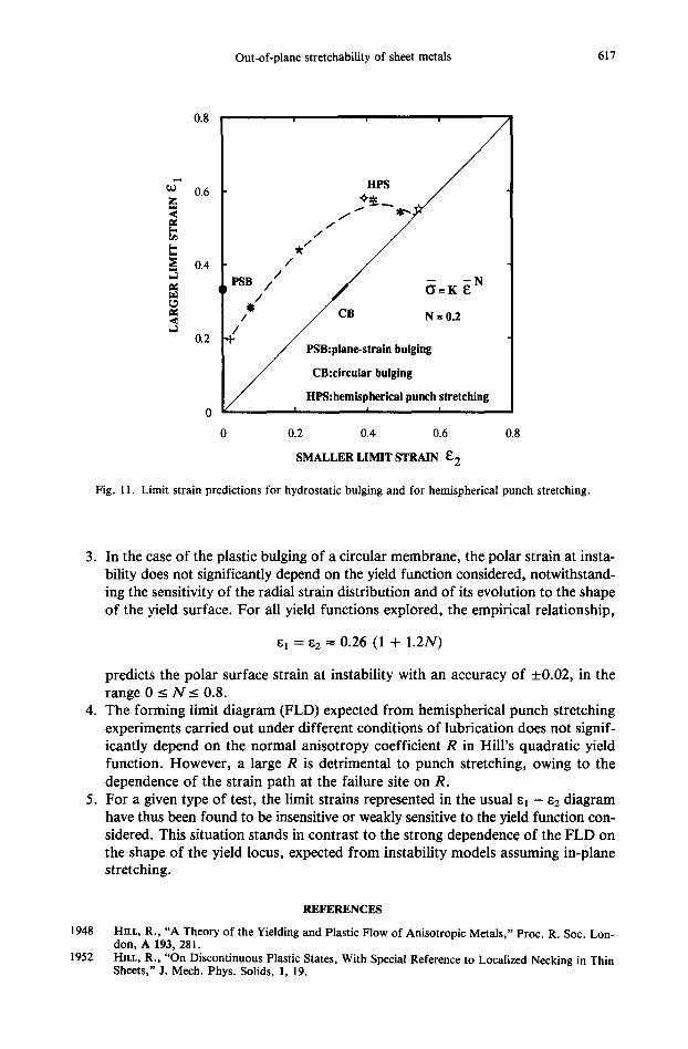
The limit strains determined in this article in different out-of-plane stretching exper- iments are summarized in Fig. 11. All derivations have been obtained with the time- independent flow theory along with the assumptions of normal anisotropy and isotropic hardening. In the case of pressurized membranes, the limit strains have been defined at the bifurcation point associated with the attainment of a maximum pressure. For the hemispherical punch test, the forming limits have been determined by analysing the local- ization process inherent in this experiment. The results are summarized as follows:
1.
2.
The limit strains depend on the type of out-of-plane stretching experiment utilized for their determination. An analytical solution is obtained for the plane-strain plastic bulging of a long strip clamped at its two edges. The hoop strain at instability does not depend on the yield surface considered. It is linked to the work-hardening exponent N by the lin- ear relationship
with an error less than 0.5°70 for 0 _< N <__ 1.
Out-of-plane stretchability of sheet metals 617
z .¢ ~e E-
_3 se
~e .¢ _3
0.8
0.6
0.4
0.2
liPS
/ * / /
PSa/// /" / N:o.
P S B ~ i n hulling
CB:circular bulging
/ ~ c a l punch s I tretching
0 0.2 0.4 0.6 0.8
SMALLER LIMIT STRAIN E2
Fig. 11. Limit strain predictions for hydrostatic bulging and for hemispherical punch stretching.
3. In the case of the plastic bulging of a circular membrane, the polar strain at insta- bility does not significantly depend on the yield function considered, notwithstand- ing the sensitivity of the radial strain distribution and of its evolution to the shape of the yield surface. For all yield functions explored, the empirical relationship,
61 ----- 62 ~--- 0.26 (1 + 1.2N)
.
.
predicts the polar surface strain at instability with an accuracy of _+0.02, in the range 0 _< N ~ 0.8. The forming limit diagram (FLD) expected from hemispherical punch stretching experiments carried out under different conditions of lubrication does not signif- icantly depend on the normal anisotropy coefficient R in Hill's quadratic yield function. However, a large R is detrimental to punch stretching, owing to the dependence of the strain path at the failure site on R. For a given type of test, the limit strains represented in the usual el - e2 diagram have thus been found to be insensitive or weakly sensitive to the yield function con- sidered. This situation stands in contrast to the strong dependence of the FLD on the shape of the yield locus, expected from instability models assuming in-plane stretching.
1948
1952
REFERENCES
HrLL, R., "A Theory of the Yielding and Plastic Flow of Anisotropic Metals," Proc. R. Soc. Lon- don, A 193, 281. HILL, R., "On Discontinuous Plastic States, With Special Reference to Localized Necking in Thin Sheets," J. Mech. Phys. Solids, 1, 19.
618 A. ZEGHLOUL and G. FERRON
1952 SWIFT, H.W., "Plastic Instability Under Plane Stress," J. Mech. Phys. Solids, 1, 1. 1962 MELLOR, P.B., "Tensile Instability in Thin-Walled Tubes," J. Mech. Eng. Sci., 4, 251. 1963 KEELER, S.P., and BACKOFEN, W.A., "Plastic Instability and Fracture in Sheets Stretched Over Rigid
Punches," Trans. ASM, 56, 25. 1967 JONES, R.H., and MELLOR, P.B., "Plastic Flow and Instability Behaviour of Thin-Walled Cylinders
Subjected to Constant-Ratio Tensile Stress," J. Strain Analysis, 2, 62. 1967 MARClNIAK, Z., and KtYCZYNSKI, K., "Limit Strains in the Processes of Stretch-Forming Sheet Metal,"
Int. J. Mech. Sci., 9, 609. 1968 COCKCROFT, M.G., and LATHAM, D.J., "Ductility and the Workability of Metals," J. Inst. Metals,
96, 33. 1970 WANG, N.M., "Large Plastic Deformation of a Circular Sheet Caused by Punch Stretching," J. Appl.
Mech., 37, 431. 1973 MARCINIAK, Z., KUCZYNSKI, K., and POKORA, T., "Influence of the Plastic Properties of a Material
on the Forming Limit Diagram for Sheet Metal in Tension," Int. J. Mech. Sci., 15, 789. 1975 GaosI~, A.K., and HECKER, S.S., "Failure in Thin Sheets Stretched over Rigid Punches," Met. Trans.,
6A, 1065. 1976 G~OSH, A.K., "A Criterion for Ductile Fracture in Sheets Under Biaxial Loading," Met. Trans., 7A,
523. 1977 ISEK1, H., MOROTA, T., and 31MM~, T., "Finite Element Method in the Analysis of the Hydrostatic
Bulging of a Sheet Metal," Bull. JSME, 20, 141. 1978 PAm¢~, A., and MEZLOR, P.B., "Predictions of Limit Strains in Sheet Metal Using a More General
Yield Criterion," Int. J. Mech. Sci., 20, 385. 1978 TWRGAAWD, V., "Effect of Kinematic Hardening on Localized Necking in Biaxially Stretched Sheets,"
Int. J. Mech. Sci., 20, 651. 1978 WANG, N.-M., and BU~DIA~SKY, B., "Analysis of Sheet Metal Stamping by a Finite-Element Method,"
J. Appl. Mech., 45, 73. 1980 NE~E, K.W., and C ~ E R , E., "Limit Strain Predictions for Strain-Rate Sensitive Anisotropic Sheets,"
Int. J. Mech. Sci., 22, 563. 1984 BUD~ANSKY, B., "Anisotropic Plasticity of Plane-lsotropic Sheets," in DVOWAK, G.J., and SHmLD,
R.T. (eds.), Mechanics of Material Behavior, Elsevier Science Publishers B.V., Amsterdam, pp. 15-29. 1985 CV~AN, K.S., LINDHOLM, U.S., and WISE, J., "Biaxial Strength of HY 80 Steel," J. Eng. Mat. Tech.,
107, 132. 1985 FEm~ON, G., and MunA-ToumL M., "Determination of the Forming Limits in Planar-lsotropic and
Temperature-Sensitive Sheet Metals," Int. J. Mech. Sei., 27, 121. 1987 BARLAT, E, "Crystallographic Texture, Anisotropic Yield Surface and Forming Limits of Sheet Met-
als," Mat. Sci. Eng., 91, 55. 1989 KNIBLOE, LR., and WAGONER, R.H., "Experimental Investigation and Finite Element Modeling of
Hemispherically Stretched Steel Sheet," Met. Trans., 20A, 1509. 1989 LI~'~, J., ZHO~, D., and BA~ELET, B., "Application of Hill's New Yield Theory to Sheet Metal Form-
i n g - Part I. Hill's 1979 Criterion and its Application to Predicting Sheet Forming Limit," Int. J. Mech. Sci., 31, 237.
1990 ZECm~O~, A., MESW~,R, R., and FELON, G., "Analytical Expressions of the Forming Limits in Bi~x- ially Stretched Sheets," Int. J. Mech. Sci., 32, 981.
1991 DUDZINSKI, D., and MOL~Am, A., "Perturbation Analysis of Thermoviscoplastic Instabilities in Biax- ial Loading," Int. J. Solids and Struct., 27, 601.
1991 HILL, R., "A Theoretical Perspective on In-Plane Forming of Sheet Metal," J. Mech. Phys. Solids, 39, 295.
1991 ZE~OUL, A., MESWa~, R., and FELON, G., "Influence of Material Parameters on the Hydrostatic Bulging of a Circular Diaphragm," Int. J. Mech. Sci., 33, 229.
Laboratoire de Physique et M6canique des Mat6riaux URA CNRS 1215, ISGMP Universit6 de Metz, lie du Saulcy 57045 Metz Cedex 1, France
(Received 6 March 1992; in final revised form 10 September 1992)