Embed Size (px)
Citation preview
Limiting Thermal Bridging and Air Infiltration Acceptable Construction Details
© Government of Ireland 2008
July 2008
1
INTRODUCTION This guide to Acceptable Construction Details (ACDs) is intended to help the construction industry achieve the performance standards in the Technical Guidance Document (TGD) to Part L of the Building Regulations 2008- Conservation of Fuel and Energy - Dwellings. This document has been developed in consultation with relevant construction industry organisations to provide a set of such details for typical constructions. This Guide This guide focuses on issues concerning thermal bridging and airtightness. The guide is presented in two sections. Section 1 discusses the general theory of insulation continuity and airtightness in construction. A common approach to the design, construction and testing methodology is considered and suggestions are made for the general improvement of the process. The use of the Acceptable Construction Details in the context of Technical Guidance Document L is discussed. A checklist identifies the essential information to be considered during design and construction. The layout and use of the ACD sheets is explained. Construction detailing can create opportunities for increased design flexibility and overall energy efficiency. The increasing significance of detailing and the principles of enhanced detail performance are discussed and illustrated using an example design specification. Finally, an overview of "How to achieve good performance in thermal bridging and air infiltration" is presented. Section 2 of this guide is in seven parts on separate web pages. Section 2 provides large scale indicative detail drawings of thermal insulation and airtightness provisions for specific construction interfaces. The co-operation of the UK authorities (Department of Communities and Local Government) is gratefully acknowledged in enabling the adaptation of the details in its publication “Limiting thermal bridging and air leakage” for official use in Ireland. The details have been modified and extended to reflect construction practice in Ireland, and have been updated to reflect the current requirements in Building Regulations. The details are accompanied by comments and checklists to assist the Designer and Builder achieve the guidance provided in Building Regulations 2008 TGD-L (Dwellings) at various stages throughout construction. These Acceptable Construction Details will also be of assistance to Building Control Authorities. Application of Acceptable Construction Details The guide and the ACDs have mainly been conceived in relation to the construction, alteration and extension of dwellings. They are also valid in non-domestic buildings of similar construction. Use of the ACDs during construction will enable the Builder to demonstrate that provision has been made to eliminate all reasonably avoidable thermal bridges in the insulation layers
2
(so far as the details apply). Further specific guidance is also to be found in the Technical Guidance Documents. Acknowledgements The Department would like to thank all those involved in the development of these Acceptable Construction Details. In particular we wish to thank the industry bodies and working groups for the time and effort contributed. This document has been produced in conjunction with HomeBond and Sustainable Energy Ireland. The Department of the Environment, Heritage and Local Government, HomeBond and SEI would like to acknowledge the following for the use of photographs in this document: Proclima Viking House Moyisover Irish Agrément Board
3
SECTION ONE Background The energy consumed by dwellings accounts for a large proportion of Ireland's total energy consumption, and of the carbon dioxide emissions which contribute to climate change. Much of this energy is accounted for in the space heating. Insulation standards for roofs, walls, windows and floors in the Building Regulations have increased over the years to improve efficiency by reducing heat loss. These standards relate to the average performance of specific elements. As standards improve, the significance of local areas of reduced insulation (thermal bridging) e.g. at joints and around the edges of window openings, and gaps in the building envelope leading to air leakage becomes increasingly important in terms of contribution to overall heating and ventilation losses from the dwelling. With average overall standards (U-values) as set in the Elemental Method in Building Regulations 2008 TGD-L (Dwellings) for instance, the proportion of the overall heat loss due to thermal bridging in average dwellings built recently is probably between 10% and 15%. The figure can be substantially higher with certain construction systems and in dwellings with particularly poor detailing. Furthermore, the typical additional heat loss due to easily avoidable air leakage is between 5% and 10%. Other side effects of thermal bridging and air leakage include:- - Surface condensation, damaging decorations and enabling mould growth - Deterioration of the building fabric caused by interstitial condensation - Occupant discomfort caused by draughts and cold rooms To reduce the impact of these and to address these problems, Insulation Continuity and Airtightness need to be thoroughly considered at all stages of design and construction. Insulation Continuity The thermal performance of a plane building element (within a particular construction) is described by its U value (W/m2K). This is a measure of the heat transmission through the element per degree of temperature difference (degrees Celsius denoted as degrees Kelvin to signal temperature difference) between the internal and external environments. Thermal bridging typically occurs at the junctions between plane building elements, e.g. at wall/roof and wall/floor junctions, and around openings, e.g. at window jambs, where the continuity of the insulation is interrupted. Thermal bridging increases the heat loss and also the risk of condensation due to the lower localised internal surface temperatures. BRE IP 1/06 describes a method of quantifying this extra heat loss at a thermal bridging by way of its linear thermal transmittance of Psi (Ψ) value in units of (W/mK). Building Regulations 2008 TGD-L (Dwellings) indicates that heat loss calculations should include the effects of thermal bridges when calculating the Energy Performance Coefficient (EPC) and Maximum Permitted Energy Performance Coefficient (MPEPC). BRE Paper IP 1/06 also describes a method of assessing the effects of the low internal surface temperature (that result from the construction) by way of the temperature factor fRsi. Depending on the intended building function, the temperature factor (fRsi) of the detail must
4
be no less than the critical factor, fCRsi, given in the paper. All of the details in Section 2 meet with the guidance in Appendix D, Building Regulations 2008 TGD-L (Dwellings) for rooms within a typical dwelling. Airtightness The airtightness of a dwelling, or its air permeability, is expressed in terms of air leakage in cubic metes per hour per square metre of the dwelling envelope area when the building is subjected to a differential pressure of 50 Pascals (m3/(h.m2)@50Pa). The dwelling envelope area is defined in this context as the total area of all floors, walls and ceilings bordering the dwelling, including elements adjoining other heated or unheated spaces. Air leakage is defined as the flow of air through gaps and cracks in the building fabric. Uncontrolled air leakage increases the amount of heat loss as warm air is displaced through the envelope by colder air from outside. Air leakage of warm damp air through the building structure can also lead to condensation within the fabric (interstitial condensation), which reduces insulation performance and causes fabric deterioration. The air permeability of a building can be determined by means of a pressure test. ATTMA TSI: 2006 discusses the methodology for air pressure testing including the test procedures, requirements and conditions of reporting. Building Regulations 2008 TGD-L (Dwellings) indicates that reasonable provision for airtightness is to achieve a pressure test result of no worse than 10m3/(h.m2)@50Pa. Current good practice for energy efficient dwellings includes achieving airtightness of 7m3/(h.m2)@50Pa and best practice is 3m3/(h.m2)@50Pa. The airtightness appropriate for a particular dwelling design will depend upon the Building Energy Rating the builder is aiming to achieve. Adopting the details in this publication will help to achieve airtightness of 10m3/(h.m2)@50Pa or better. All materials used for airtightness should comply with Part D of the Building Regulations “Materials and Workmanship” ENSURING INSULATION CONTINUITY AND AIRTIGHTNESS The following guidance may be considered good practice for delivering insulation continuity and airtightness in construction. The guidance considers projects at three stages – Design, Construction and Testing.
5
Design Stage The complexity of the modern building envelope requires that consideration is given to achieving insulation continuity and airtightness early in design. This two stage process should be done at both strategic and detail level. Consideration at the strategic level involves the primary construction and insulation method (masonry cavity insulation, insulated timber frame, etc.) and selecting the primary air barrier elements (plaster finishes, sheathing boards, etc.). The choices made dictate the philosophy for the remainder of the design and construction process. At the detail level it is important that the design builds upon the above strategy showing the builder how to maintain insulation continuity and airtightness. Achieving continuity in practice requires that the designer: - Identifies the components which form the insulation layer and air barrier in each part of
the construction - Develops details that achieve continuity of the insulation and air barrier between each
part of the construction and the next - Communicates the intentions clearly to the builder The air barrier line – The air barrier is a layer within the building envelope which will adequately restrict the passage of air between the internal and external environments. The barrier should closely follow the line of the inside face of the insulation in the exposed elements of the fabric of the building. Consideration should be given at an early stage as to which layer of each exposed element of the fabric will form the primary air barrier, and to the junctions between them. The details in Section 2 assume the air barrier will be formed largely by internal plaster or plasterboard finishes. Pen-on-section drawings – It is good practice to mark up the air barrier line on the architectural main section drawings as a bold distinguishable line. If the air barrier is continuous, it should be possible to trace around the whole section without lifting the pen. If you have to lift the pen, you have discontinuity and a potential air leak. The details in Section 2 show the air barrier as a bold dark blue line. Larger scale drawings - It is good practice to prepare large scale drawings of sensitive points in the design. These drawings should clearly identify the insulation and the air barrier. The drawings should be issued to all relevant parties identifying how the integrity of the insulation layer and air barrier is maintained at particularly complex interfaces. The following will help achieve insulation continuity and airtightness: - Keep it simple! Simple designs are more likely to get built right. - Decide which layer of the construction provides the air barrier. Stick with this. Use the
pen-on-section test to check continuity and to identify key details.
6
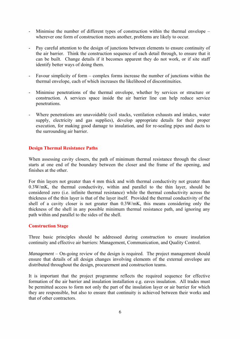
- Minimise the number of different types of construction within the thermal envelope – wherever one form of construction meets another, problems are likely to occur.
- Pay careful attention to the design of junctions between elements to ensure continuity of
the air barrier. Think the construction sequence of each detail through, to ensure that it can be built. Change details if it becomes apparent they do not work, or if site staff identify better ways of doing them.
- Favour simplicity of form – complex forms increase the number of junctions within the
thermal envelope, each of which increases the likelihood of discontinuities. - Minimise penetrations of the thermal envelope, whether by services or structure or
construction. A services space inside the air barrier line can help reduce service penetrations.
- Where penetrations are unavoidable (soil stacks, ventilation exhausts and intakes, water
supply, electricity and gas supplies), develop appropriate details for their proper execution, for making good damage to insulation, and for re-sealing pipes and ducts to the surrounding air barrier.
Design Thermal Resistance Paths When assessing cavity closers, the path of minimum thermal resistance through the closer starts at one end of the boundary between the closer and the frame of the opening, and finishes at the other. For thin layers not greater than 4 mm thick and with thermal conductivity not greater than 0.3W/mK, the thermal conductivity, within and parallel to the thin layer, should be considered zero (i.e. infinite thermal resistance) while the thermal conductivity across the thickness of the thin layer is that of the layer itself. Provided the thermal conductivity of the shell of a cavity closer is not greater than 0.3W/mK, this means considering only the thickness of the shell in any possible minimum thermal resistance path, and ignoring any path within and parallel to the sides of the shell. Construction Stage Three basic principles should be addressed during construction to ensure insulation continuity and effective air barriers: Management, Communication, and Quality Control. Management – On-going review of the design is required. The project management should ensure that details of all design changes involving elements of the external envelope are distributed throughout the design, procurement and construction teams. It is important that the project programme reflects the required sequence for effective formation of the air barrier and insulation installation e.g. eaves insulation. All trades must be permitted access to form not only the part of the insulation layer or air barrier for which they are responsible, but also to ensure that continuity is achieved between their works and that of other contractors.
7
It may be prudent when compiling the programme to include an “Air Tight” milestone. Knowledge of this date may permit management to schedule thorough envelope pre-test inspections and test dates in advance of the end of the project. Testing during the construction stage along with good quality control procedures allows problems to be identified and corrected early in the construction process prior to final testing. Communication and Education – Personnel involved in procurement and constructing the building fabric should understand the need for insulation continuity and airtightness. The more aware people are of the issues, the less likely essential components will be engineered out of the design for cost savings, and the more receptive site staff will be to requests for a higher standard of workmanship. Awareness may be raised at key stages by briefing procurement offices and site tool-box talks. The detailed pen-on-section drawings may be issued to all parties clearly identifying where and how insulation continuity and the air barrier will be maintained. Operatives directly involved in constructing the insulation and air barrier should be encouraged to draw attention to difficulties and request direction rather than to muddle through. Operatives not directly involved in the building fabric should also be made aware of the importance of insulation continuity and the air barrier and of flagging up any breaches through these “lines of defence”. They should also be required to remedy potential thermal bridges or air leakage routes brought about by their own activities, or to seek help from other trades, depending on the nature of the breach. Quality Control –Many contractors now have systems in place for monitoring the quality of their processes and products. Experience shows that the Quality Assurance (QA) should be extended to check for insulation continuity and airtightness. The ACD sheets can be used for this. An essential QA control is that insulation continuity and airtightness are considered during all design changes and material substitutions affecting the external envelope. An ill-formed design change may jeopardise the final performance of the building envelope. The QA process should ideally involve inspection of finished works especially the building envelope. This will enable management to check that all works are properly constructed prior to being covered over. Testing Stage Insulation Continuity – Inspection of the insulation will largely be a qualitative assessment during construction. This should be a series of inspections as recommended above. These inspections might be recorded as a series of brief reports supplemented by photographs as well as the completed ACDs. Airtightness – The air permeability test is usually undertaken as the building nears completion. The external envelope must be practicably complete with all windows, doors and service penetrations installed and air sealed. The test is a quantitative assessment which culminates in either a pass or a fail result against a design value.
8
It can be useful to perform air tightness checks on sections of the building during construction to identify areas of leakage prior to completion of finishes. Where the building fails to meet the required airtightness standard, inspections might be undertaken utilising tracer smoke to identify areas of excessive air leakage. Remedial works must then be undertaken to improve the airtightness performance of the fabric. Depending on the design and the formation of the air barrier, this might be difficult and time consuming, ultimately delaying completion. IMPLEMENTING ACCEPTABLE CONSTRUCTION DETAILS INTO DESIGN To make best use of the ACDs, the following will be helpful. - Detail drawings (sections and plans) identifying the line of the air barrier - List of Acceptable Construction Details incorporated into the design - List of the builder’s own details incorporated into the design - Specification of the air barrier materials / elements - Details of air barrier junctions and interfaces including means of sealing service
penetrations - Evidence of Site Quality Control during construction (photos, check sheets, etc.) Use of Acceptable Construction Details Section 2 of this publication provides a series of Acceptable Construction Details showing typical junction interfaces for various construction types.
Group 1 Cavity insulation Group 2 External insulation Group 3 Internal insulation Group 4 Timber Frame Group 5 Steel Frame Group 6 Hollow Block Internal Insulation
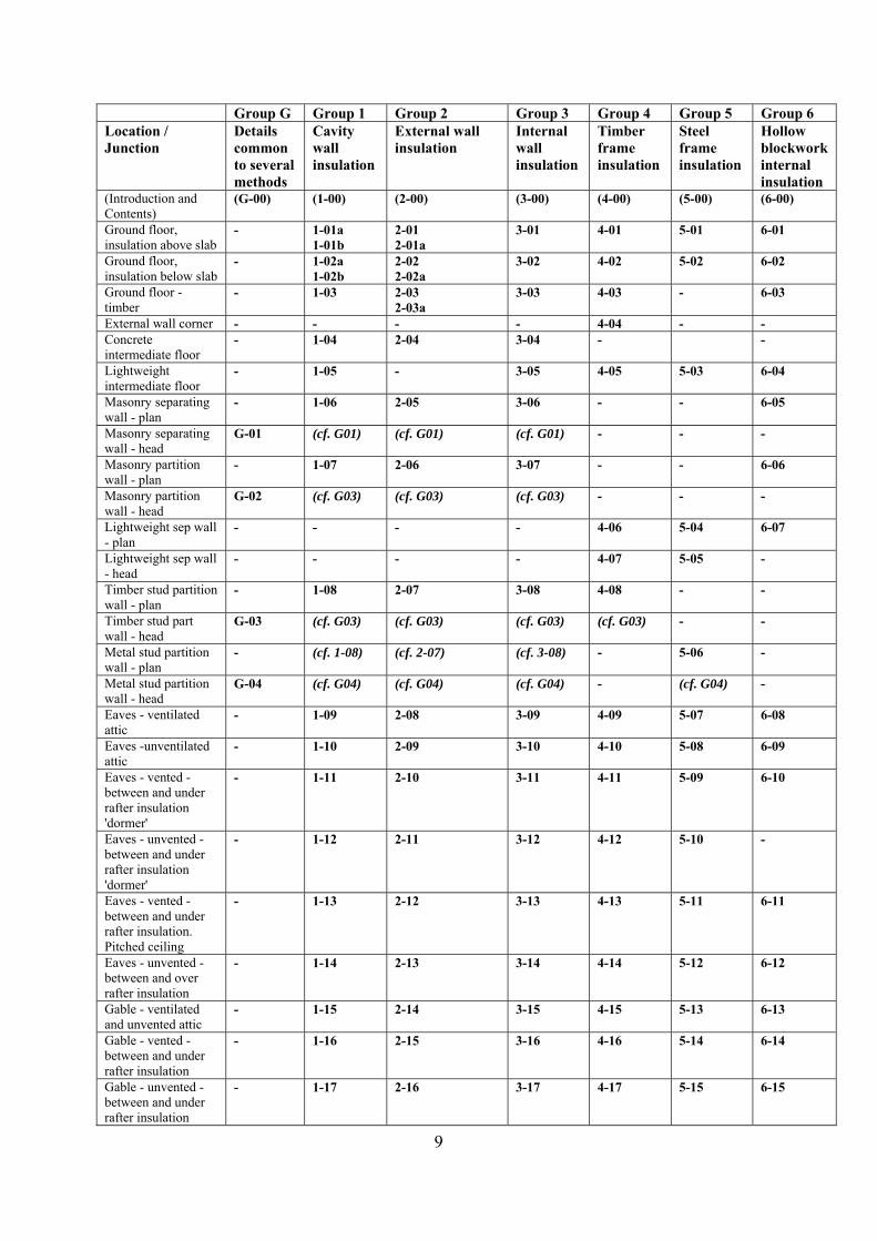
As well as the above, a small number of details are applicable across several construction types and are referred to as Group G, General details. The following is a list of details currently published. Where more than one detail is provided for a junction either detail can be used. Each set of details contain an Introduction page outlining particular guidance for that group of details. The information on this Introduction page should be taken into account when using each set of details.
9
Group G Group 1 Group 2 Group 3 Group 4 Group 5 Group 6 Location / Junction
Details common to several methods
Cavity wall insulation
External wall insulation
Internal wall insulation
Timber frame insulation
Steel frame insulation
Hollow blockwork internal insulation
(Introduction and Contents)
(G-00) (1-00) (2-00) (3-00) (4-00) (5-00) (6-00)
Ground floor, insulation above slab
- 1-01a 1-01b
2-01 2-01a
3-01 4-01 5-01 6-01
Ground floor, insulation below slab
- 1-02a 1-02b
2-02 2-02a
3-02 4-02 5-02 6-02
Ground floor - timber
- 1-03 2-03 2-03a
3-03 4-03 - 6-03
External wall corner - - - - 4-04 - - Concrete intermediate floor
- 1-04 2-04 3-04 - -
Lightweight intermediate floor
- 1-05 - 3-05 4-05 5-03 6-04
Masonry separating wall - plan
- 1-06 2-05 3-06 - - 6-05
Masonry separating wall - head
G-01 (cf. G01) (cf. G01) (cf. G01) - - -
Masonry partition wall - plan
- 1-07 2-06 3-07 - - 6-06
Masonry partition wall - head
G-02 (cf. G03) (cf. G03) (cf. G03) - - -
Lightweight sep wall - plan
- - - - 4-06 5-04 6-07
Lightweight sep wall - head
- - - - 4-07 5-05 -
Timber stud partition wall - plan
- 1-08 2-07 3-08 4-08 - -
Timber stud part wall - head
G-03 (cf. G03) (cf. G03) (cf. G03) (cf. G03) - -
Metal stud partition wall - plan
- (cf. 1-08) (cf. 2-07) (cf. 3-08) - 5-06 -
Metal stud partition wall - head
G-04 (cf. G04) (cf. G04) (cf. G04) - (cf. G04) -
Eaves - ventilated attic
- 1-09 2-08 3-09 4-09 5-07 6-08
Eaves -unventilated attic
- 1-10 2-09 3-10 4-10 5-08 6-09
Eaves - vented - between and under rafter insulation 'dormer'
- 1-11 2-10 3-11 4-11 5-09 6-10
Eaves - unvented - between and under rafter insulation 'dormer'
- 1-12 2-11 3-12 4-12 5-10 -
Eaves - vented - between and under rafter insulation. Pitched ceiling
- 1-13 2-12 3-13 4-13 5-11 6-11
Eaves - unvented - between and over rafter insulation
- 1-14 2-13 3-14 4-14 5-12 6-12
Gable - ventilated and unvented attic
- 1-15 2-14 3-15 4-15 5-13 6-13
Gable - vented - between and under rafter insulation
- 1-16 2-15 3-16 4-16 5-14 6-14
Gable - unvented - between and under rafter insulation
- 1-17 2-16 3-17 4-17 5-15 6-15
10
Group G Group 1 Group 2 Group 3 Group 4 Group 5 Group 6 Details
common to several methods
Cavity wall insulation
External wall insulation
Internal wall insulation
Timber frame insulation
Steel frame insulation
Hollow blockwork internal insulation
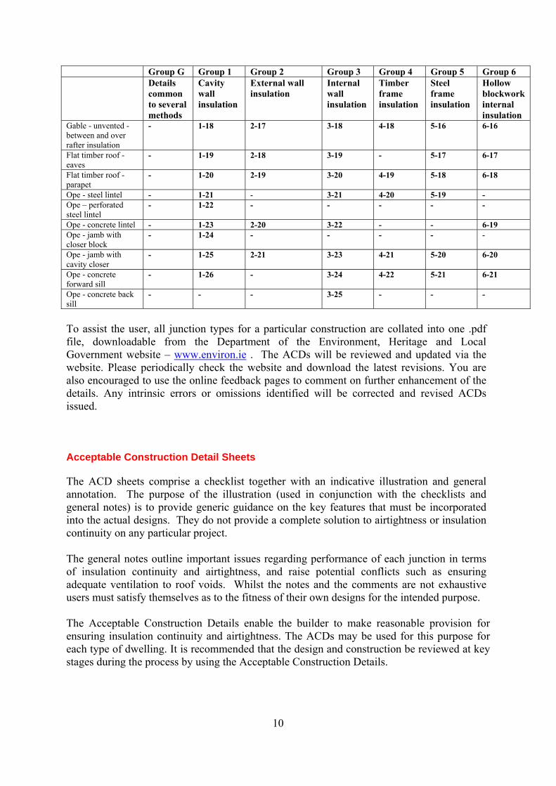
Gable - unvented - between and over rafter insulation
- 1-18 2-17 3-18 4-18 5-16 6-16
Flat timber roof - eaves
- 1-19 2-18 3-19 - 5-17 6-17
Flat timber roof - parapet
- 1-20 2-19 3-20 4-19 5-18 6-18
Ope - steel lintel - 1-21 - 3-21 4-20 5-19 - Ope – perforated steel lintel
- 1-22 - - - - -
Ope - concrete lintel - 1-23 2-20 3-22 - - 6-19 Ope - jamb with closer block
- 1-24 - - - - -
Ope - jamb with cavity closer
- 1-25 2-21 3-23 4-21 5-20 6-20
Ope - concrete forward sill
- 1-26 - 3-24 4-22 5-21 6-21
Ope - concrete back sill
- - - 3-25 - - -
To assist the user, all junction types for a particular construction are collated into one .pdf file, downloadable from the Department of the Environment, Heritage and Local Government website – www.environ.ie . The ACDs will be reviewed and updated via the website. Please periodically check the website and download the latest revisions. You are also encouraged to use the online feedback pages to comment on further enhancement of the details. Any intrinsic errors or omissions identified will be corrected and revised ACDs issued. Acceptable Construction Detail Sheets The ACD sheets comprise a checklist together with an indicative illustration and general annotation. The purpose of the illustration (used in conjunction with the checklists and general notes) is to provide generic guidance on the key features that must be incorporated into the actual designs. They do not provide a complete solution to airtightness or insulation continuity on any particular project. The general notes outline important issues regarding performance of each junction in terms of insulation continuity and airtightness, and raise potential conflicts such as ensuring adequate ventilation to roof voids. Whilst the notes and the comments are not exhaustive users must satisfy themselves as to the fitness of their own designs for the intended purpose. The Acceptable Construction Details enable the builder to make reasonable provision for ensuring insulation continuity and airtightness. The ACDs may be used for this purpose for each type of dwelling. It is recommended that the design and construction be reviewed at key stages during the process by using the Acceptable Construction Details.
11
Substitution of Contractors Own Designs and Proprietary Designs If use of details other than Acceptable Construction Details is proposed for use in construction they should meet the alternative requirements given in Paragraph 1.3.3.2 in Building Regulations 2008 TGD L – (Dwellings). DEAP Calculations If all details for a dwelling type are installed as per the ACDs, the dwelling fabric design will qualify for the value of y =.08 in DEAP calculations as described in DEAP Appendix K. If all the details within a dwelling are not completed to the ACDs individual Ψ values must be obtained and the value of y calculated. Individual Ψ values may be obtained in the following ways:
a) the default Ψ value for Acceptable Construction Details from Building Regulations 2008 TGD-L (Dwellings) Table D1
b) the Ψ values published for internal junctions and some commonly used details outlined in appendix 2 to this document
c) Ψ values for other details which are assessed in accordance with the BRE IP1/06 “Assessing the effects of thermal bridging at junctions and around openings” and BRE Report BR 497 “Conventions for calculating linear thermal transmittance and temperature factors” in accordance with Appendix D of Building Regulations 2008 TGD-L (Dwellings) 1
d) or they can be derived from measurement. 1
For an explanation of the calculation of the value of y see Appendix 1 of this document and the sample calculations given.
1.For any details that are not as recommended in Acceptable Construction Details or Appendix 2 of this document, it is necessary to determine their temperature factor.
12
DESIGN FLEXIBILITY AND ENHANCEMENT Detailing significance Traditional design and construction practice has concentrated on insulating exposed walls, floors and roofs of buildings, to reduce thermal transmittances (U-values). Until recently there has been limited focus on the heat losses that occur at the junctions between construction elements and around openings, or on the heat losses that occur because of uncontrolled air leakage. As standards of insulation have improved, the proportion of the total heat loss that may be attributed to these causes has increased. Design example The design example shown below has been modelled using DEAP 2008 to provide an insight into the significance that non-repeating thermal bridging has in terms of a dwelling’s heat loss and CO2 emissions. The design is based on the example in Building Regulations 2008 TGD-L (Dwellings) (Appendix E) which is required to result in Maximum Permitted Energy Performance Coefficient (MPEPC) of 0.6 and a Maximum Permitted Carbon Performance Coefficient of 0.69. Three different levels of detailing have been assumed. Construction details which are not Acceptable Construction Details (y=0.15 W/m2K) Acceptable Construction Details (y = 0.08 W/m2K) Improved detailing, using ψ values lower than those for Acceptable Construction Details, for the lintels, ground floor perimeter and gables (y = 0.04 W/m2K) Example specifications Floor 0.20 W/m2K Wall 0.25 W/m2K Window 1.7 W/m2K Door 3.0 W/m2K Roof 0.15 W/m2K Air permeability 8m3/m2/h@50Pa (0.4 ACH - ambient) Boiler Gas-fired condensing boiler 90% seasonal efficiency Controls Programmer, room thermostat, TRV's and boiler interlock Secondary heating Balanced-flue gas fire Lighting 75% low energy Ventilation Natural with intermittent extract fans The increasing significance of heat loss via the non-repeating thermal bridges is illustrated in the chart below. Targeting the thermal performance of key areas such as lintels, the wall to ground floor junction and wall to ceiling insulation at gables is shown to have a significant effect on both heat loss and the corresponding carbon emissions.
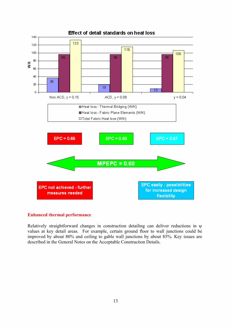
Enhanced thermal performance Relatively straightforward changes in construction detailing can deliver reductions in ψ values at key detail areas. For example, certain ground floor to wall junctions could be improved by about 80% and ceiling to gable wall junctions by about 85%. Key issues are described in the General Notes on the Acceptable Construction Details.
13
14
AIR TIGHTNESS STRATEGY Design Stage Simplify built form where possible. Define the line of the air barrier as early as possible. Mark up large scale sections with a bold coloured line. Consider and rationalise construction sequencing. Redefine the air barrier route and insulation strategy in critical areas to simplify details and avoid problems. Decide and specify which materials will form the air barrier. Consider: - Material air permeability - Buildability - Position within the construction - Long term durability Consider junction details between air barrier materials: - Practicality of forming the seals on site - Durability of the seals, especially where not accessible for future remedial work. Minimise the number of service penetrations through the external wall. Consider how service penetrations will be sealed. Rationalise service routes and penetrations. Highlight air barrier critical elements and junctions on construction drawings. Apportion responsibility for sealing critical junctions to specific trades. Construction Stage Appoint a site “air barrier manager” to coordinate and inspect the overall formation of the air barrier. Brief the whole construction team (not just management) on the need for and importance of the air barrier. Inform the team of the air barrier line, the materials which will form the barrier and the critical junctions. Encourage operatives to draw attention to unforeseen difficulties rather than using makeshift solutions. Air barrier management to undertake: - Coordination of the formation of the air barrier - Site quality assurance - Check and sign off all “hidden” air barrier elements before covering up. Review the construction as work proceeds to identify any weaknesses in the air barrier strategy / areas not previously considered and feed this information back to the design team. Establish solutions to any problems identified. Undertake airtightness testing at the earliest possible opportunity. Use an established pressure testing company capable of giving good diagnostic feedback. All materials and workmanship including air tightness tapes and sealants to be supplied and completed as per guidelines in Technical Guidance Document D.
15
ACHIEVING THERMAL CONTINUITY AND AIR TIGHTNESS (1) Principles In designing and building for low heat loss, both good insulation and control of air infiltration are needed. Good attention to detailing is necessary during installation for insulation to work effectively and to ensure unwanted air infiltration is eliminated as far as practicable. This translates into "thermal continuity of the insulation" and "air tightness of the building". How to achieve thermal continuity - and why For thermal insulation to be effective, it needs to be continuous. This means no gaps between the insulation sheets or batts. It also means no way for cold air to circulate freely on the warm side the insulation. - Insulation boards with stepped rather than flat butt joints give better continuity. - Cut cavity insulation to suit. Butt the sheets tightly to each other, as well as tight up
against cavity closers and loose fill insulation. - Install roof insulation over the top course of blocks at the eaves, prior to felting at the
roof having brought the wall insulation up to the top of the wall and bring the wall insulation right up to the top.
Good practice Use of a purpose made air tight membrane as the air barrier round the envelope, with joints taped and sealed, particularly at junctions in the external wall, around service penetrations, and at internal and external corners can further increase air tightness beyond the performance of the barrier options given in the diagrams. To limit condensation, it may be helpful to restrict the contact of non-breathable insulation on timber studs, joists or other sections to less than 50% of the section perimeter. With internal dry lining, a vapour barrier to prevent interstitial condensation on the structure is particularly important. To reduce cracking and help air tightness, it may be helpful to tape mesh onto wall/ceiling junctions in advance of plastering. Other good practice notes are provided on diagrams for specific junctions.
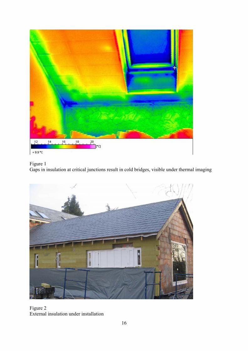
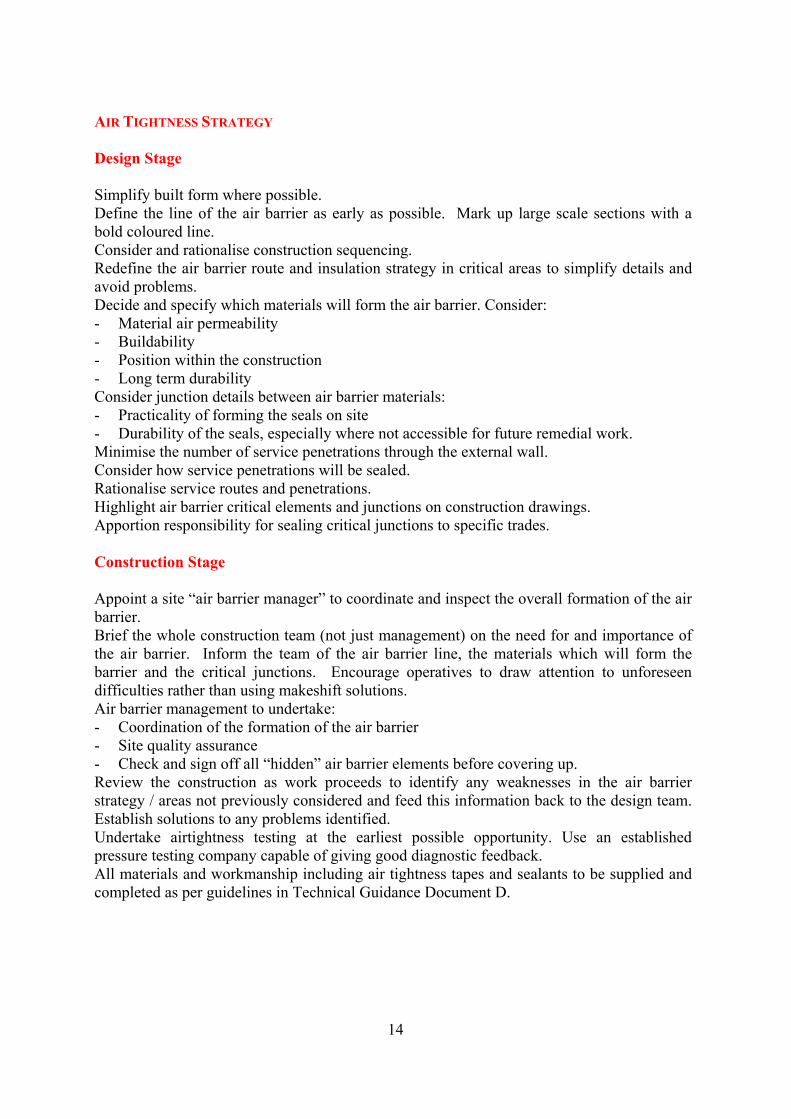
Figure 1 Gaps in insulation at critical junctions result in cold bridges, visible under thermal imaging
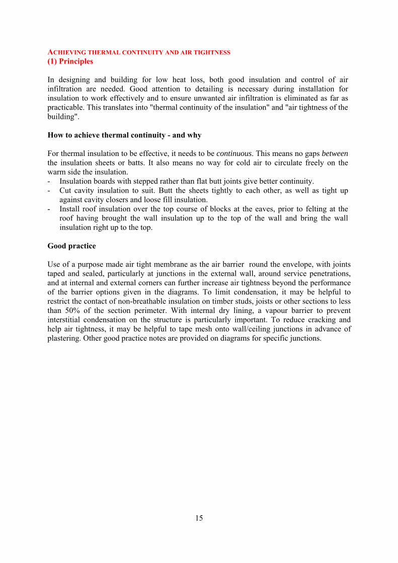
Figure 2 External insulation under installation
16
How to achieve air tightness - and why Air tightness means cutting out unwanted draughts. Draughts can be so slight as to be imperceptible, but even slight draughts increase heat loss, sometimes dramatically. The way to good air tightness is a continuous air-resistant layer all around the inside of the building. This includes under and around the ground floor, across the external walls and under the roof, to seal the inside from the outside. With masonry walls - whether concrete block or concrete - this is most easily done by using a wet plaster finish. It can also be done by using dry-lining boards and by taking extra care to seal around all gaps, all perimeters, and at windows and external doors. With timber frame or steel frame walls, it's most easily done by using plasterboard board with perimeters and joints all thoroughly sealed. Points to watch:- - Plaster between the joists at suspended timber floors - Make sure there's no gap along the skirtings at floor level - Where pipes or wires pass through the outside wall or the roof, seal around them to
draught-proof the opening - Tape around window and external door frames to stop the draught at the edges
Figure 3 Sealing the junction between the joist and the external wall
17
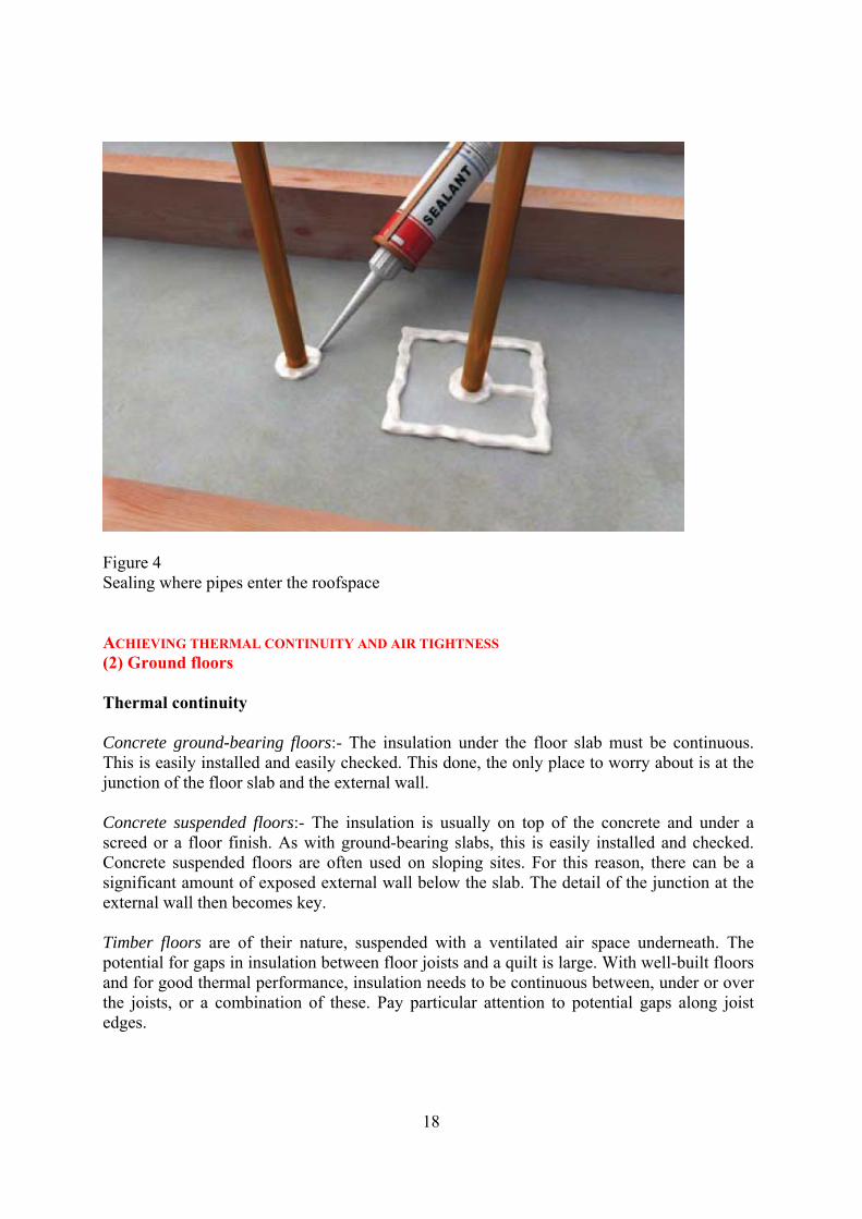
Figure 4 Sealing where pipes enter the roofspace ACHIEVING THERMAL CONTINUITY AND AIR TIGHTNESS (2) Ground floors Thermal continuity Concrete ground-bearing floors:- The insulation under the floor slab must be continuous. This is easily installed and easily checked. This done, the only place to worry about is at the junction of the floor slab and the external wall. Concrete suspended floors:- The insulation is usually on top of the concrete and under a screed or a floor finish. As with ground-bearing slabs, this is easily installed and checked. Concrete suspended floors are often used on sloping sites. For this reason, there can be a significant amount of exposed external wall below the slab. The detail of the junction at the external wall then becomes key. Timber floors are of their nature, suspended with a ventilated air space underneath. The potential for gaps in insulation between floor joists and a quilt is large. With well-built floors and for good thermal performance, insulation needs to be continuous between, under or over the joists, or a combination of these. Pay particular attention to potential gaps along joist edges.
18
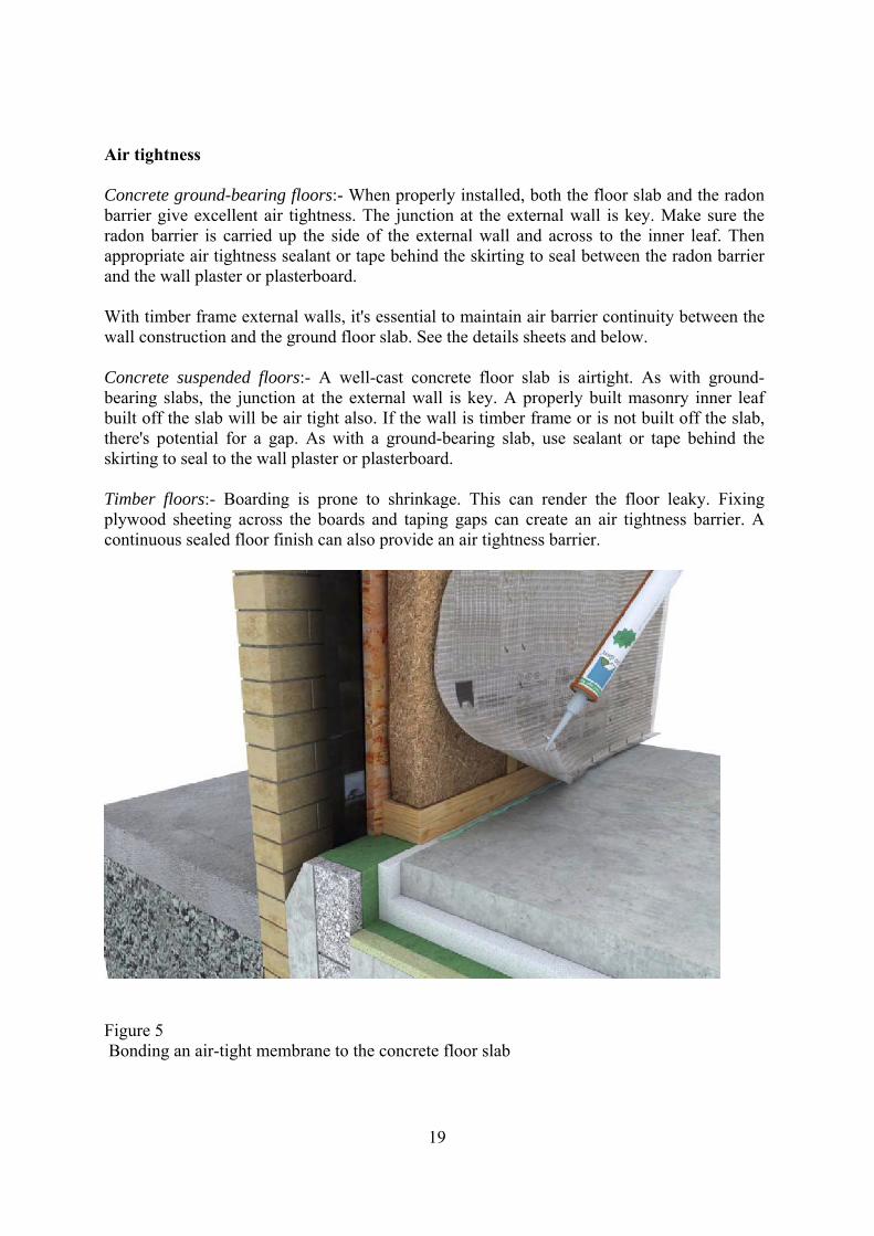
Air tightness Concrete ground-bearing floors:- When properly installed, both the floor slab and the radon barrier give excellent air tightness. The junction at the external wall is key. Make sure the radon barrier is carried up the side of the external wall and across to the inner leaf. Then appropriate air tightness sealant or tape behind the skirting to seal between the radon barrier and the wall plaster or plasterboard. With timber frame external walls, it's essential to maintain air barrier continuity between the wall construction and the ground floor slab. See the details sheets and below. Concrete suspended floors:- A well-cast concrete floor slab is airtight. As with ground-bearing slabs, the junction at the external wall is key. A properly built masonry inner leaf built off the slab will be air tight also. If the wall is timber frame or is not built off the slab, there's potential for a gap. As with a ground-bearing slab, use sealant or tape behind the skirting to seal to the wall plaster or plasterboard. Timber floors:- Boarding is prone to shrinkage. This can render the floor leaky. Fixing plywood sheeting across the boards and taping gaps can create an air tightness barrier. A continuous sealed floor finish can also provide an air tightness barrier.
Figure 5 Bonding an air-tight membrane to the concrete floor slab
19
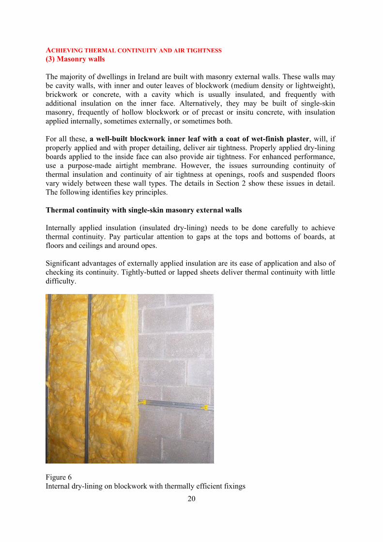
ACHIEVING THERMAL CONTINUITY AND AIR TIGHTNESS (3) Masonry walls The majority of dwellings in Ireland are built with masonry external walls. These walls may be cavity walls, with inner and outer leaves of blockwork (medium density or lightweight), brickwork or concrete, with a cavity which is usually insulated, and frequently with additional insulation on the inner face. Alternatively, they may be built of single-skin masonry, frequently of hollow blockwork or of precast or insitu concrete, with insulation applied internally, sometimes externally, or sometimes both. For all these, a well-built blockwork inner leaf with a coat of wet-finish plaster, will, if properly applied and with proper detailing, deliver air tightness. Properly applied dry-lining boards applied to the inside face can also provide air tightness. For enhanced performance, use a purpose-made airtight membrane. However, the issues surrounding continuity of thermal insulation and continuity of air tightness at openings, roofs and suspended floors vary widely between these wall types. The details in Section 2 show these issues in detail. The following identifies key principles. Thermal continuity with single-skin masonry external walls Internally applied insulation (insulated dry-lining) needs to be done carefully to achieve thermal continuity. Pay particular attention to gaps at the tops and bottoms of boards, at floors and ceilings and around opes. Significant advantages of externally applied insulation are its ease of application and also of checking its continuity. Tightly-butted or lapped sheets deliver thermal continuity with little difficulty.
Figure 6 Internal dry-lining on blockwork with thermally efficient fixings
20
21
Thermal continuity with cavity masonry external walls Well-built cavity walls have clean cavities, with cavity insulation held firmly against the inner leaf. Insulation sheets with lapped or tongue-and-groove edges, or which are of fibrous type, can be butted tightly against each other and give reasonable thermal continuity. - Clear all debris including mortar snots from cavity as work progresses to prevent thermal
bridging between the inner and outer leaf. - Cavity insulation should be cut to suit. Tightly butt sheets to each other and to
surrounding cavity closers. - Fix insulation tight to the outer face of the inner block work leaf, to prevent air
circulation between the block and insulation reducing the performance of the insulation layer.
Air tightness with cavity masonry external walls The nature of cavity construction makes it difficult to achieve good air tightness by sealing externally. The simplest way to achieve good air tightness is to plaster the inner leaf. Dry lining with proper sealing of all perimeters and joints will also achieve good air tightness. The key areas to watch are junctions at opes, at floors, and at service penetrations - see sections 5-10.
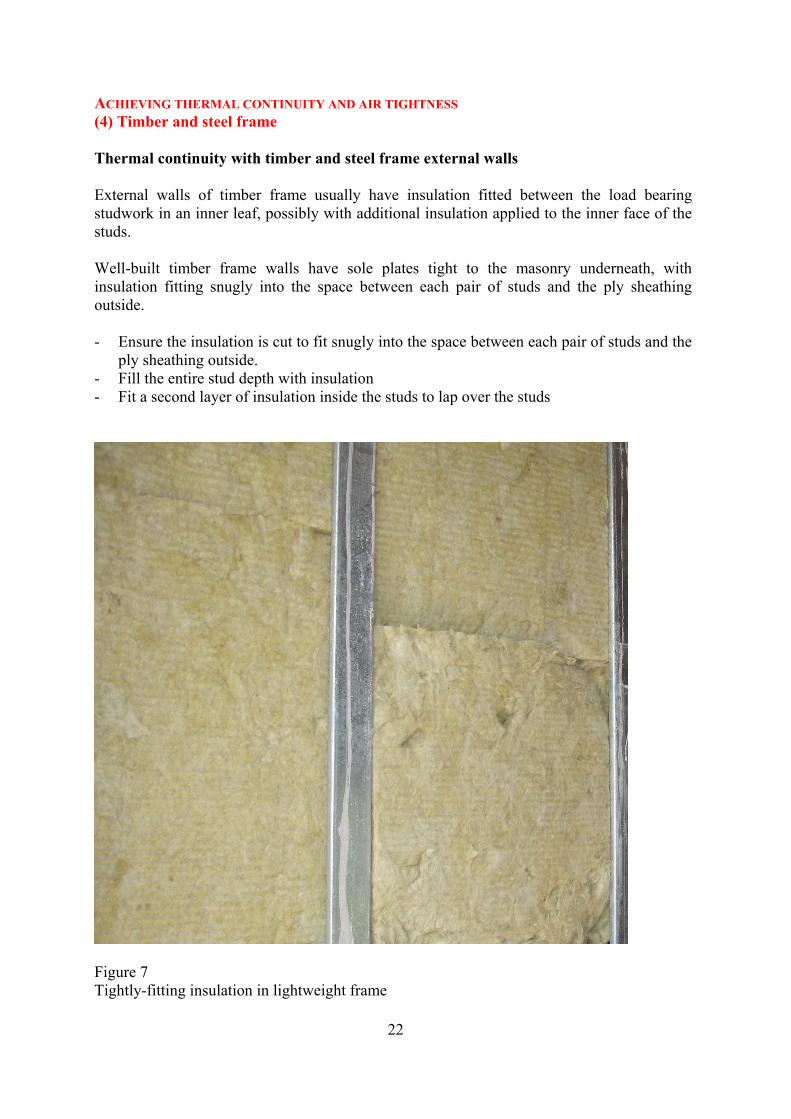
ACHIEVING THERMAL CONTINUITY AND AIR TIGHTNESS (4) Timber and steel frame Thermal continuity with timber and steel frame external walls External walls of timber frame usually have insulation fitted between the load bearing studwork in an inner leaf, possibly with additional insulation applied to the inner face of the studs. Well-built timber frame walls have sole plates tight to the masonry underneath, with insulation fitting snugly into the space between each pair of studs and the ply sheathing outside. - Ensure the insulation is cut to fit snugly into the space between each pair of studs and the
ply sheathing outside. - Fill the entire stud depth with insulation - Fit a second layer of insulation inside the studs to lap over the studs
Figure 7 Tightly-fitting insulation in lightweight frame
22
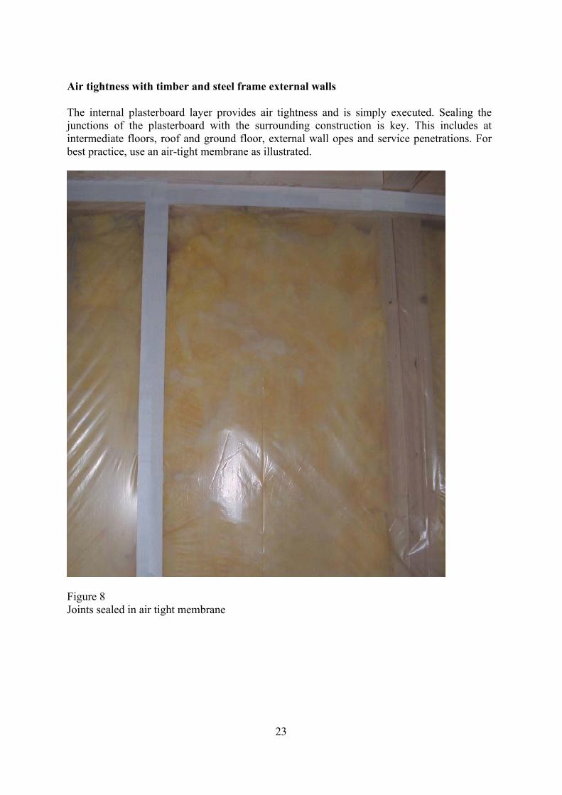
Air tightness with timber and steel frame external walls The internal plasterboard layer provides air tightness and is simply executed. Sealing the junctions of the plasterboard with the surrounding construction is key. This includes at intermediate floors, roof and ground floor, external wall opes and service penetrations. For best practice, use an air-tight membrane as illustrated.
Figure 8 Joints sealed in air tight membrane
23
24
ACHIEVING THERMAL CONTINUITY AND AIR TIGHTNESS (5) Intermediate floors Thermal continuity with timber intermediate floors If the thermal insulation is in the cavity or is external type, thermal continuity at the junction of the intermediate floor and the outside wall happens almost of its own accord. So long as the cavity insulation is continuous across the joist hangers, continuity is achieved. If the insulation is on the inner face of the external wall, thermal continuity requires greater attention to detail. There is a potential cold bridge all along the zone of the suspended floor. If the insulation is on the inner face of the external wall, make sure that insulation is carried up (or down) between the floor joists and tight to the timbers on all sides. Continue the insulation up the wall from below and make sure it's continuous at ceiling level. Thermal continuity with concrete intermediate floors As with timber floors, if the thermal insulation is in the cavity or is external type, thermal continuity at the junction of the intermediate floor and the outside wall is achieved readily. If the insulation is on the inner face of the external wall, thermal continuity is not possible. Air tightness at intermediate floors is a matter of closing the gaps above and below where floor spans onto the external wall, and around any joists, beams or joist hangers. In timber floors, where joists run parallel to the external wall, or when hangers are used for joists requiring support, air tightness is achieved by bedding the hangers in mortar, and by plastering the external wall the same as is done for the rest of the wall. With timber frame or with dry-lined masonry, carry the boards into the floor zone and tape around the joists or hangers, see below. Where timber joists span onto the external wall, carry the boards into the floor zone and tape around the joists or hangers, as per Figure 10. With concrete intermediate floors, when the floor spans onto the wall, pay attention to any gap under the slab, especially with precast concrete slabs. If a blockwork wall is built off the floor slab above, this will give an excellent basis for air tightness once the blockwork is plastered right down to the slab.
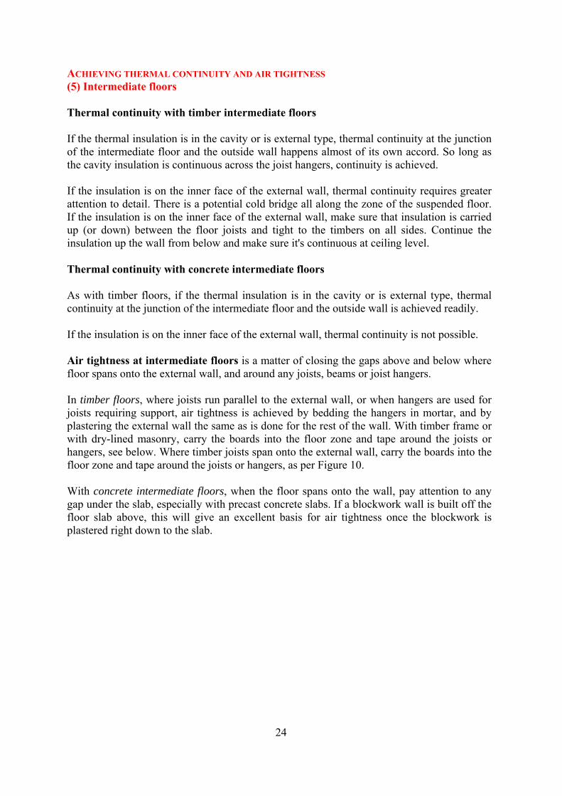
Figure 9 Sealing at intermediate floors: First stage: point up around joists
25
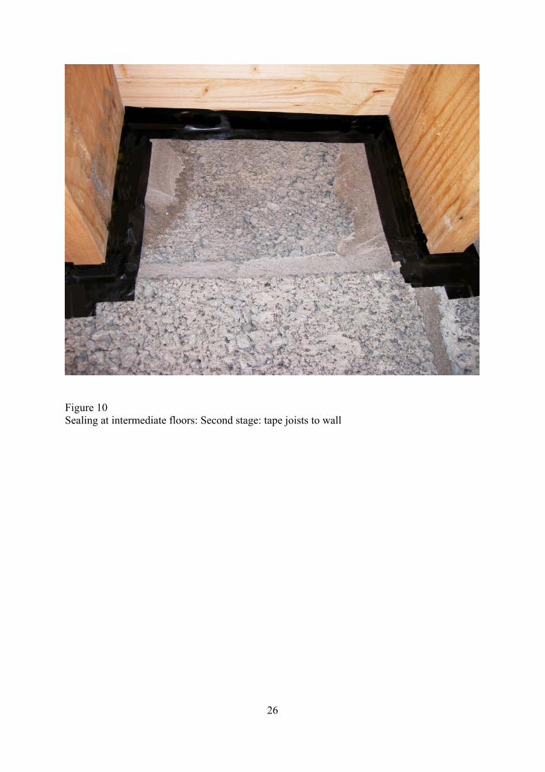
Figure 10 Sealing at intermediate floors: Second stage: tape joists to wall
26
27
ACHIEVING THERMAL CONTINUITY AND AIR TIGHTNESS (6) Separating wall junctions The concern at separating walls is the structural continuity which is usual between the separating wall and the exterior wall. This can result in breaks both in thermal insulation and also in air tightness. Thermal continuity The issues which arise are similar to those with intermediate floors or with staircases. With a masonry structure, insulation in a cavity, or exterior insulation, both deliver thermal continuity. This is because the insulation runs uninterrupted either externally or in the cavity and outside the junction of the walls. With an internally insulated masonry structure, the insulated dry lining needs to be returned for at least 1 metre along the separating wall. Air tightness at separating wall junctions Where a separating wall is of cavity construction, and where the cavity is joined to a cavity in the external wall, close off the cavity paths to cut down on air routes. This can often be done using the fire stopping required under Building Regulations Part B.
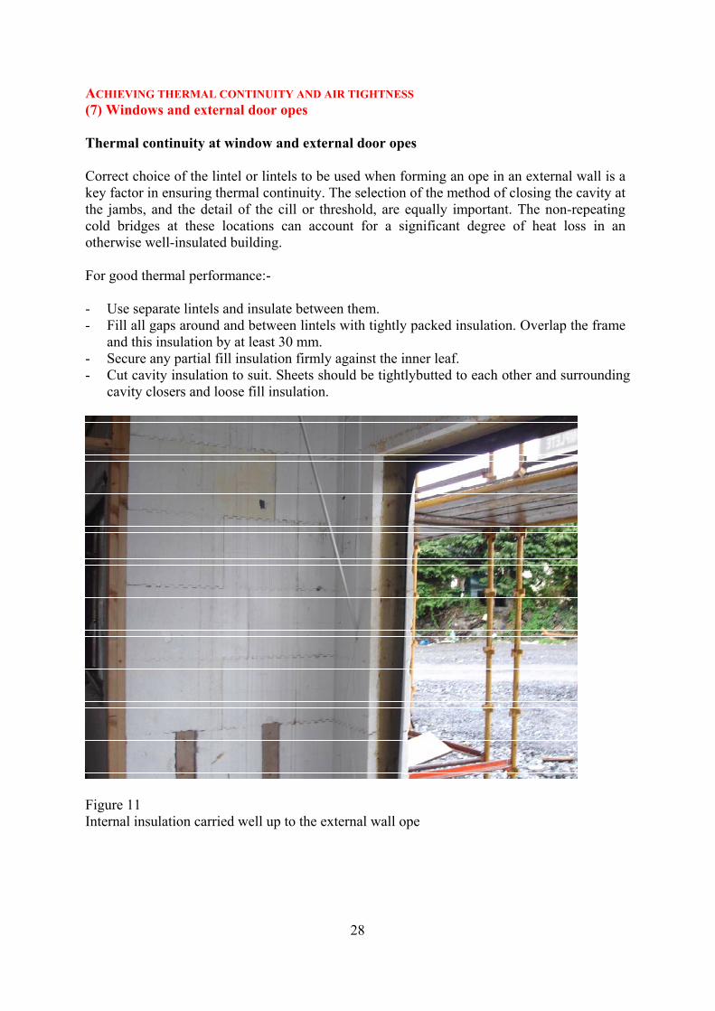
ACHIEVING THERMAL CONTINUITY AND AIR TIGHTNESS (7) Windows and external door opes Thermal continuity at window and external door opes Correct choice of the lintel or lintels to be used when forming an ope in an external wall is a key factor in ensuring thermal continuity. The selection of the method of closing the cavity at the jambs, and the detail of the cill or threshold, are equally important. The non-repeating cold bridges at these locations can account for a significant degree of heat loss in an otherwise well-insulated building. For good thermal performance:- - Use separate lintels and insulate between them. - Fill all gaps around and between lintels with tightly packed insulation. Overlap the frame
and this insulation by at least 30 mm. - Secure any partial fill insulation firmly against the inner leaf. - Cut cavity insulation to suit. Sheets should be tightlybutted to each other and surrounding
cavity closers and loose fill insulation.
Figure 11 Internal insulation carried well up to the external wall ope
28
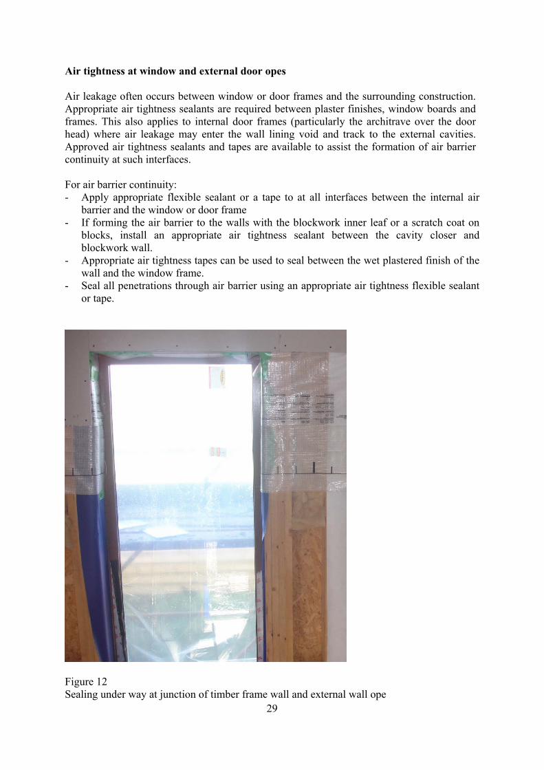
Air tightness at window and external door opes Air leakage often occurs between window or door frames and the surrounding construction. Appropriate air tightness sealants are required between plaster finishes, window boards and frames. This also applies to internal door frames (particularly the architrave over the door head) where air leakage may enter the wall lining void and track to the external cavities. Approved air tightness sealants and tapes are available to assist the formation of air barrier continuity at such interfaces. For air barrier continuity: - Apply appropriate flexible sealant or a tape to at all interfaces between the internal air
barrier and the window or door frame - If forming the air barrier to the walls with the blockwork inner leaf or a scratch coat on
blocks, install an appropriate air tightness sealant between the cavity closer and blockwork wall.
- Appropriate air tightness tapes can be used to seal between the wet plastered finish of the wall and the window frame.
- Seal all penetrations through air barrier using an appropriate air tightness flexible sealant or tape.
Figure 12
29Sealing under way at junction of timber frame wall and external wall ope
30
ACHIEVING THERMAL CONTINUITY AND AIR TIGHTNESS (8) Trickle ventilators Research has shown that if relative humidity levels exceed 70% for prolonged periods, there is a high probability that the condensation occurring on cold surfaces will lead to mould growth. A ventilation rate of between 0.5 and 1.5 air changes per hour (ach) for the whole dwelling will usually be sufficient to control condensation. Permanently opened ventilators provide either fixed or controlled fresh air background ventilation to provide adequate air supply for occupants and comprise of louvered ventilation openings located within the external walls or trickle ventilators located in the window frames. Where wall mounted permanent ventilation openings are used it is necessary to provide plastic ducting from the inlet wall mounted grille to the room permanently opened outlet vent to minimise thermal bridging and infiltration through each wall component as per 'Extract fan' specification set out in section (9). Some trickle ventilators can permit significant levels of leakage to occur during the air leakage pressurisation test. It is important to check the manufacturer’s product literature to ensure that the ventilators provide a sufficient level of air tightness when closed and that they are correctly installed.
31
ACHIEVING THERMAL CONTINUITY AND AIR TIGHTNESS (9) Service penetrations Holes and chases are formed for many different services by different specialist contractors. They may be in roof spaces (recessed light fittings, water pipes, soil vent pipes, rainwater pipes, ventilation ducts, television cables); in external walls (soil and waste pipes, electrical cables) and in ground floors (soil and waste pipes, incoming mains). Penetrations may also be required behind bath panels, shower trays, kitchen units and into service shafts. A key element in maintaining thermal continuity and air tightness around service opes is to agree standard sealing procedures with subcontractors and make sure they have the right materials and tools. Try to locate the following so as to minimise services and structure penetrations through the envelope • W.C. toilet overflows • Kitchen cooker hood extracts • Condensing boiler flues • Outside taps • Soil vent pipes • Waste pipes • Trickle vents in walls • Air intake vents • Canopies to entrances • Metal balconies • ESB connections and meters • Gas connections and meters • Security alarm systems • External security lighting • External security cameras and sensors Thermal continuity and air tightness at service penetrations For good thermal performance and air tightness:- - Core drill service penetrations to minimise damage to the insulation layer. - Make good any damage caused to the insulation layer by filling any gaps with loose
fibrous insulation or approved expanding foam. - Drill holes to provide a snug fit and reduce oversize to a minimum. - All penetrations through the air barrier line must be effectively sealed following
installation of the services. This can be achieved with the use of appropriate air tightness tape, air tightness grommets or air tightness sealants.
- When installing socket outlets or switch plates in an air barrier formed by a plasterboard lining, apply a continuous ribbon of dabbing sealant compound around the hole and metal electrical enclosure prior to installing the plasterboard, as this will ensure good seal between box and plaster board and the cable penetrations and the metal box, providing greatest structural integrity for this application. This will reduce air leakage through the sockets /
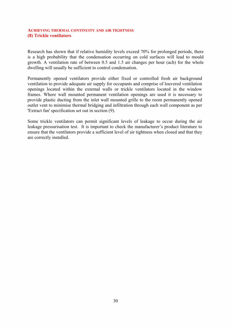
switches into the void beyond. Consider using proprietary gasketted socket boxes and membranes. Construction of a services zone inside the air tightness barrier can also reduce the number of penetrations in the barrier. Recessed light fittings may permit air leakage to breach the plasterboard ceiling line into the voids or attics beyond. They should never be allowed to penetrate the primary air barrier unless the units are of an air sealed type or a further secondary air barrier formed beyond. This needs a special detail because of the fire risk. Extract fans should be installed and sealed to prevent air leakage occurring through plasterboard finishes. A continuous ribbon of adhesive should be installed around the duct penetration at the air tightness barrier. Where possible the ducts should also be sealed to the blockwork inner leaf. Extract fans may also be fitted with external flaps to minimise air infiltration through the unit.
Figure 13 Sealing around connection to electrical socket outlet
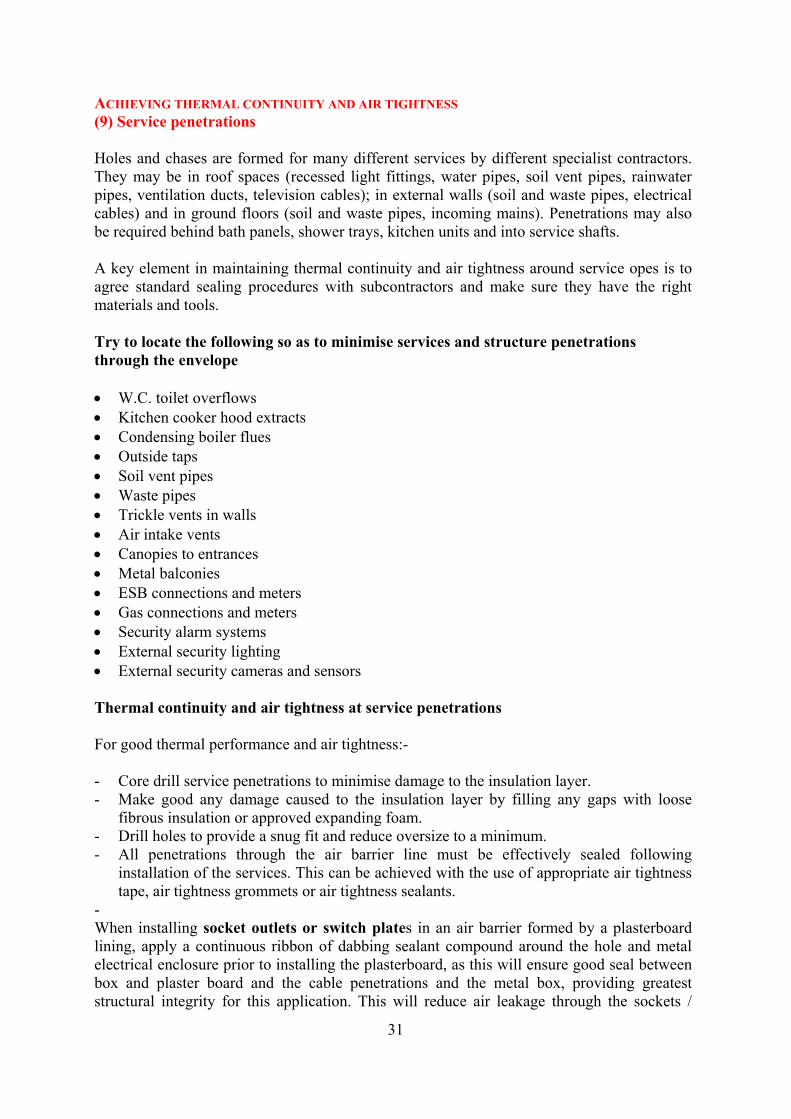
Figure 14 Ply backing on lightweight frame, to hang services and minimise penetrations through insulation and air tightness barrier
32
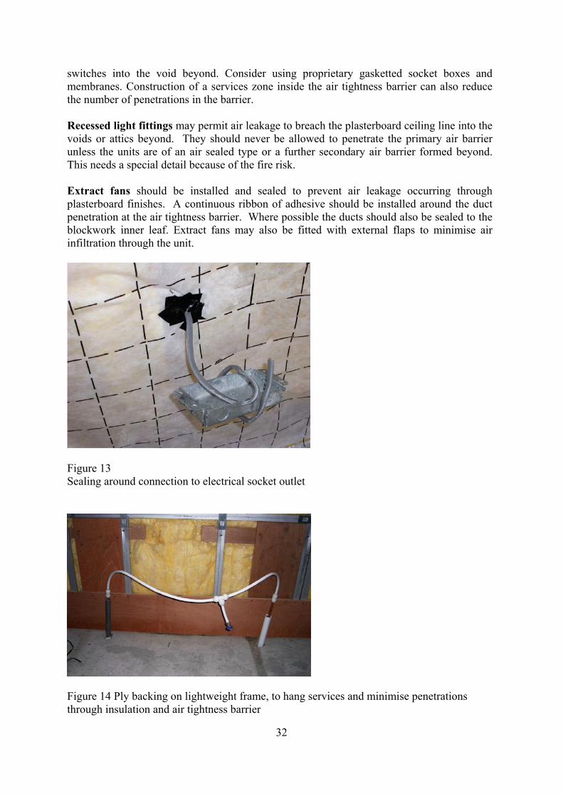
ACHIEVING THERMAL CONTINUITY AND AIR TIGHTNESS (10) In the roof Discontinuity between wall and roof insulation at eaves / verge Roof insulation should be installed to minimise the effects of thermal bridging at the eaves. Attention must be paid to the timing of installation of insulation at the eaves to ensure that it is effective as it is impractical to install when the roof has been completed The insulation should be laid over the top course of blocks and the wall insulation installed right up to the top of the wall. Thermal continuity under the attic For best practice, in cold roof spaces, use insulation over the ceiling joists, to eliminate the cold bridge otherwise caused by the joist. Air tightness under the attic Proprietary attic trap doors with low air permeability characteristics should be fitted in lieu of site manufactured doors. Where site manufactured doors are installed these should be complemented with draught stripping to minimise air leakage into the attic space above. Dormers The plasterboard cheek linings will form the air barrier. The linings should form a continuous air barrier and be sealed to the window frames. Proprietary products are available to assist the formation of air barrier continuity at such interfaces.
Figure 15
33Sealing around frame of access hatch to attic
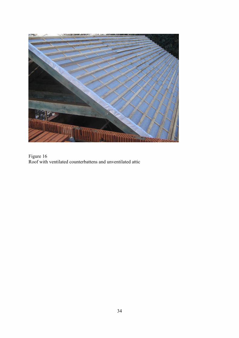
Figure 16 Roof with ventilated counterbattens and unventilated attic
34
35
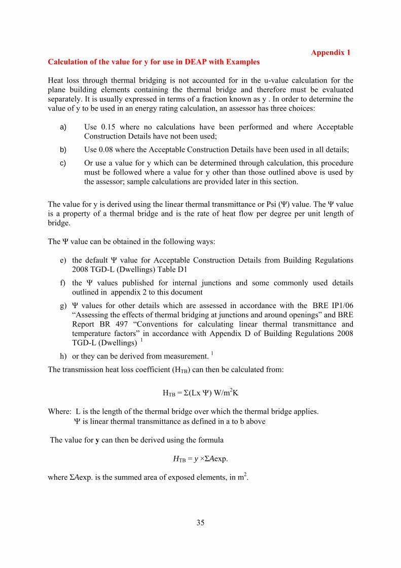
Appendix 1 Calculation of the value for y for use in DEAP with Examples Heat loss through thermal bridging is not accounted for in the u-value calculation for the plane building elements containing the thermal bridge and therefore must be evaluated separately. It is usually expressed in terms of a fraction known as y . In order to determine the value of y to be used in an energy rating calculation, an assessor has three choices:
a) Use 0.15 where no calculations have been performed and where Acceptable Construction Details have not been used;
b) Use 0.08 where the Acceptable Construction Details have been used in all details;
c) Or use a value for y which can be determined through calculation, this procedure must be followed where a value for y other than those outlined above is used by the assessor; sample calculations are provided later in this section.
The value for y is derived using the linear thermal transmittance or Psi (Ψ) value. The Ψ value is a property of a thermal bridge and is the rate of heat flow per degree per unit length of bridge. The Ψ value can be obtained in the following ways:
e) the default Ψ value for Acceptable Construction Details from Building Regulations 2008 TGD-L (Dwellings) Table D1
f) the Ψ values published for internal junctions and some commonly used details outlined in appendix 2 to this document
g) Ψ values for other details which are assessed in accordance with the BRE IP1/06 “Assessing the effects of thermal bridging at junctions and around openings” and BRE Report BR 497 “Conventions for calculating linear thermal transmittance and temperature factors” in accordance with Appendix D of Building Regulations 2008 TGD-L (Dwellings) 1
h) or they can be derived from measurement. 1
The transmission heat loss coefficient (HTB) can then be calculated from:
HTB = Σ(Lx Ψ) W/m2K
Where: L is the length of the thermal bridge over which the thermal bridge applies. Ψ is linear thermal transmittance as defined in a to b above The value for y can then be derived using the formula
HTB = y ×ΣAexp. where ΣAexp. is the summed area of exposed elements, in m2.
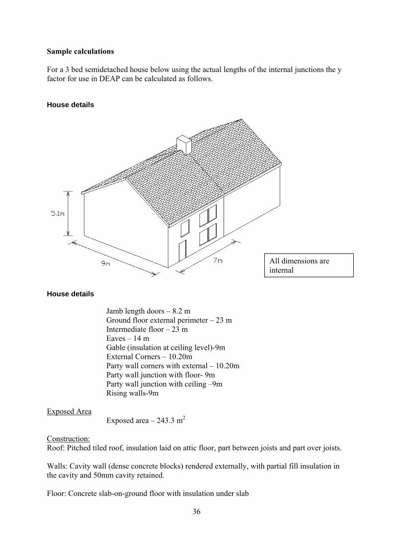
Sample calculations For a 3 bed semidetached house below using the actual lengths of the internal junctions the y factor for use in DEAP can be calculated as follows. House details
All dimensions are internal
House details
Jamb length doors – 8.2 m Ground floor external perimeter – 23 m Intermediate floor – 23 m Eaves – 14 m Gable (insulation at ceiling level)-9m External Corners – 10.20m Party wall corners with external – 10.20m Party wall junction with floor- 9m Party wall junction with ceiling –9m Rising walls-9m
Exposed Area Exposed area – 243.3 m2
Construction: Roof: Pitched tiled roof, insulation laid on attic floor, part between joists and part over joists. Walls: Cavity wall (dense concrete blocks) rendered externally, with partial fill insulation in the cavity and 50mm cavity retained. Floor: Concrete slab-on-ground floor with insulation under slab
36
37
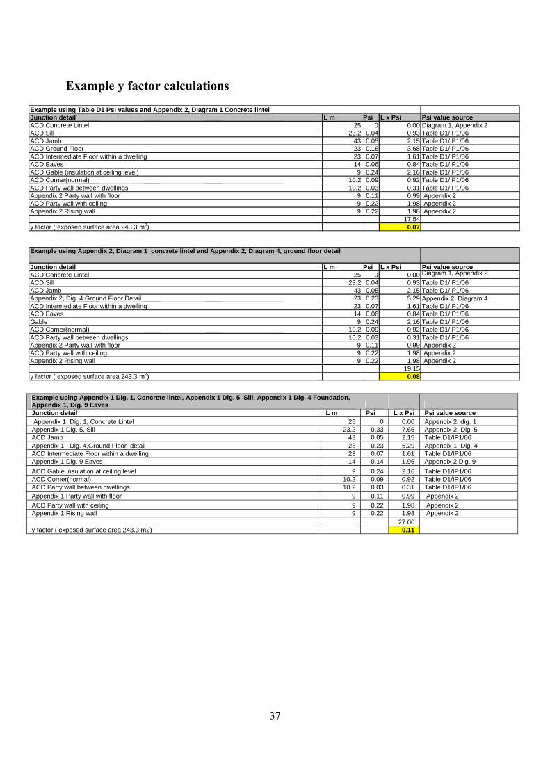
Example y factor calculations
Example using Table D1 Psi values and Appendix 2, Diagram 1 Concrete lintelJunction detail L m Psi L x Psi Psi value sourceACD Concrete Lintel 25 0 0.00 Diagram 1, Appendix 2ACD Sill 23.2 0.04 0.93 Table D1/IP1/06ACD Jamb 43 0.05 2.15 Table D1/IP1/06ACD Ground Floor 23 0.16 3.68 Table D1/IP1/06ACD Intermediate Floor within a dwelling 23 0.07 1.61 Table D1/IP1/06ACD Eaves 14 0.06 0.84 Table D1/IP1/06ACD Gable (insulation at ceiling level) 9 0.24 2.16 Table D1/IP1/06ACD Corner(normal) 10.2 0.09 0.92 Table D1/IP1/06ACD Party wall between dwellings 10.2 0.03 0.31 Table D1/IP1/06Appendix 2 Party wall with floor 9 0.11 0.99 Appendix 2ACD Party wall with ceiling 9 0.22 1.98 Appendix 2Appendix 2 Rising wall 9 0.22 1.98 Appendix 2
17.54 y factor ( exposed surface area 243.3 m2) 0.07
Example using Appendix 2, Diagram 1 concrete lintel and Appendix 2, Diagram 4, ground floor detail
Junction detail L m Psi L x Psi Psi value sourceACD Concrete Lintel 25 0 0.00 Diagram 1, Appendix 2ACD Sill 23.2 0.04 0.93 Table D1/IP1/06ACD Jamb 43 0.05 2.15 Table D1/IP1/06Appendix 2, Dig. 4 Ground Floor Detail 23 0.23 5.29 Appendix 2, Diagram 4ACD Intermediate Floor within a dwelling 23 0.07 1.61 Table D1/IP1/06ACD Eaves 14 0.06 0.84 Table D1/IP1/06Gable 9 0.24 2.16 Table D1/IP1/06ACD Corner(normal) 10.2 0.09 0.92 Table D1/IP1/06ACD Party wall between dwellings 10.2 0.03 0.31 Table D1/IP1/06Appendix 2 Party wall with floor 9 0.11 0.99 Appendix 2ACD Party wall with ceiling 9 0.22 1.98 Appendix 2Appendix 2 Rising wall 9 0.22 1.98 Appendix 2
19.15 y factor ( exposed surface area 243.3 m2) 0.08
Example u ng Appendix 1 Dig. 1, Concrete lintel, Appendix 1 Dig. 5 Sill, Appendix 1 Dig. 4 Foundation, siAppendix ig. 9 Eaves 1, D Junction detail L m Psi L x Psi alue source Psi v Appendix 1, Dig. 1, Concrete Lintel 25 0 0.00 Appendix 2, dig. 1 Appendix 1 Dig. 5, Sill 23.2 0.33 7.66 Appendix 2, Dig. 5 ACD Jamb 43 0.05 2.15 Table D1/IP1/06 Appendix 1, Dig. 4,Ground Floor detail 23 0.23 5.29 Appendix 1, Dig. 4 ACD Intermediate Floor within a dwelling 23 0.07 1.61 Table D1/IP1/06 Appendix 1 Dig. 9 Eaves 14 0.14 1.96 Appendix 2 Dig. 9 ACD Gable insulation at ceiling level 9 0.24 2.16 Table D1/IP1/06 ACD Corner(normal) 10.2 0.09 0.92 Table D1/IP1/06 ACD Party wall between dwellings 10.2 0.03 0.31 Table D1/IP1/06 Appendix 1 Party wall with floor 9 0.11 0.99 Appendix 2 ACD Party wall with ceiling 9 0.22 1.98 Appendix 2 Appendix 1 Rising wall 9 0.22 1.98 Appendix 2 27.00 y factor ( exposed surface area 243.3 m2) 0.11
Appendix 2
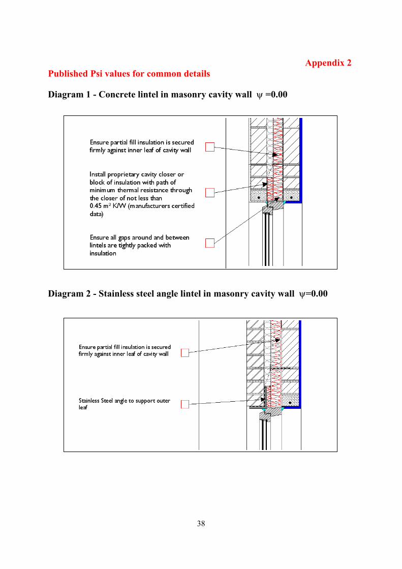
Published Psi values for common details Diagram 1 - Concrete lintel in masonry cavity wall ψ =0.00
38
Diagram 2 - Stainless steel angle lintel in masonry cavity wall ψ=0.00
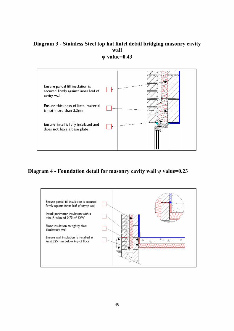
Diagram 3 - Stainless Steel top hat lintel detail bridging masonry cavity wall
ψ value=0.43
39
Diagram 4 - Foundation detail for masonry cavity wall ψ value=0.23
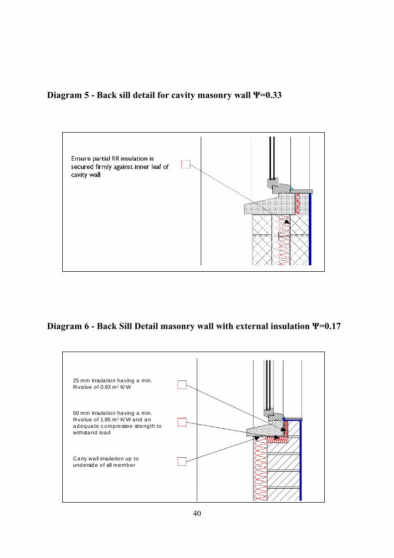
Diagram 5 - Back sill detail for cavity masonry wall Ψ=0.33
40
Diagram 6 - Back Sill Detail masonry wall with external insulation Ψ=0.17
25 mm Insulation having a min. R-value of 0.93 m2 K/W 50 mm Insulation having a min. R-value of 1.85 m2 K/W and an adequate compressive strength to withstand load Carry wall insulation up to underside of sill member
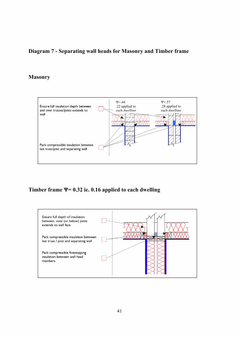
Diagram 7 - Separating wall heads for Masonry and Timber frame Masonry
Timber frame Ψ= 0.32 ie. 0.16 appli
Ψ=.44 .22 applied to each dwelling
41
ed to each dwelling
Ψ=.57 .28 applied to each dwelling
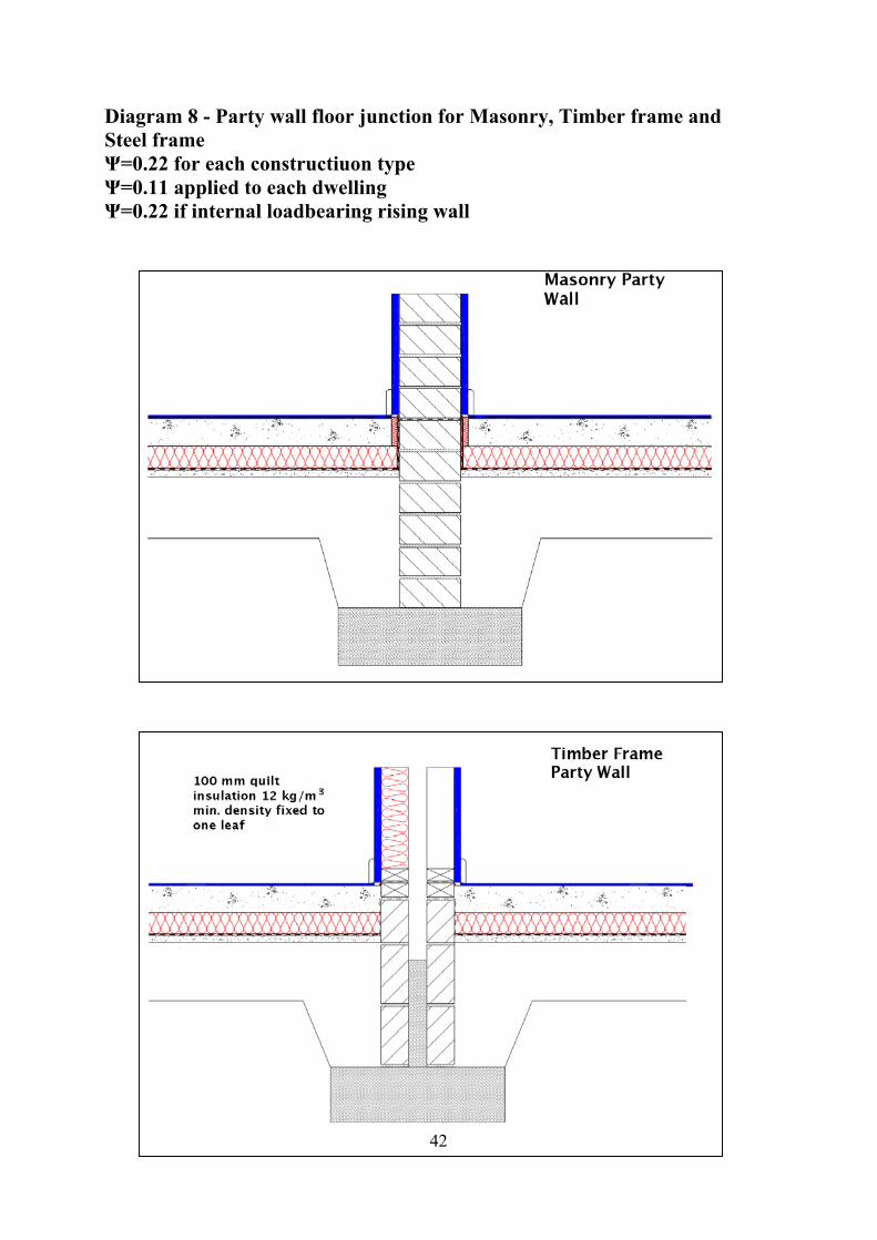
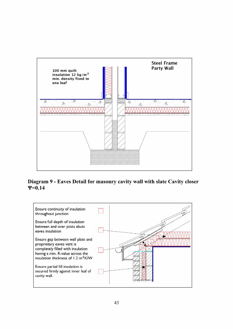
Diagram 8 - Party wall floor junction for Masonry, Timber frame and Steel frame Ψ=0.22 for each constructiuon type Ψ=0.11 applied to each dwelling Ψ=0.22 if internal loadbearing rising wall
42
43
Diagram 9 - Eaves Detail for masonry cavity wall with slate Cavity closer Ψ=0.14
44
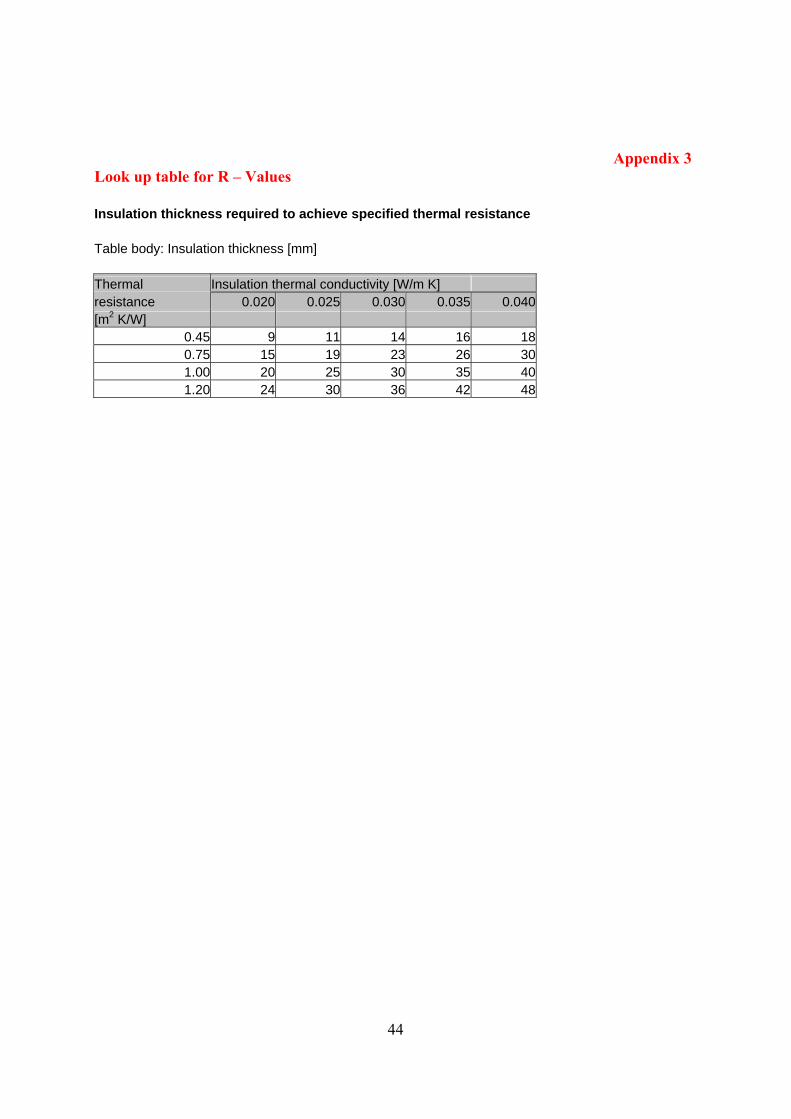
Appendix 3 Look up table for R – Values Insulation thickness required to achieve specified thermal resistance Table body: Insulation thickness [mm] Thermal Insulation thermal conductivity [W/m K] resistance 0.020 0.025 0.030 0.035 0.040[m2 K/W]
0.45 9 11 14 16 180.75 15 19 23 26 301.00 20 25 30 35 401.20 24 30 36 42 48
45
GLOSSARY ACH – air changes per hour Air barrier - a line through the envelope of the dwelling where the barrier to air leakage will be. Air leakage - the uncontrolled flow of air through gaps and cracks in the fabric of dwellings (sometimes referred to as infiltration, exfiltration or draughts). Air Permeability - is the physical property used to measure Air Tightness of the building fabric. It is defined as air leakage rate per envelope area at the test reference pressure differential across the building envelope of 50 Pascal (50N/m2) Cavity barrier - a construction provided to close a concealed space against penetration of smoke or flame, or provided to restrict the movement of smoke or flame within such a space. Cavity closer - masonry unit or plastics component that closes a cavity at the vertical sides of an opening CPC - Carbon Performance Coefficient - the calculated carbon dioxide emission rate of the building divided by that of the reference dwelling in Building Regulations 2008 TGD-L (Dwellings) Appendix C. Dewpoint is the temperature at which air becomes saturated with vapour. EPC - Energy Performance Coefficient -the calculated primary energy consumption of the proposed dwelling divided by that of the reference dwelling, Appendix C, Building Regulations 2008 TGD-L (Dwellings). Appropriate air tightness sealant - sealant should be fit for purpose and should comply with Part D of the Building Regulations -Materials and Workmanship. Appropriate air tightness tape - tape fit for purpose and should comply with Part D of the Building Regulations -Materials and Workmanship. Interstitial condensation - condensation within building elements. MPCPC - Maximum Permitted Carbon Performance Coefficient MPEPC - Maximum Permitted Energy Performance Coefficient
46
DOCUMENTS REFERRED TO Building Regulations 2008 Technical Guidance Document L Conservation of Fuel and Energy – Dwellings BRE Information Paper IP 1/06 – Assessing the effects of thermal bridging at junctions and around openings, 2006 BRE Report BR 497, Conventions for calculating linear thermal transmittance and temperature factors, BRE, 2007 HomeBond House Building Manual 6th Edition EST Guide GPG224 – Improving airtightness in dwellings, 2005 Edition. Further information on airtightness principles and practice is contained within this document ATTMA TS1 – Measuring air permeability of building envelopes, 2006 Edition. URL: www.environ.ie/en/DevelopmentandHousing/BuildingStandards/ URL: www.sei.ie/epbd/deap/