Embed Size (px)
Citation preview
INSTALLATION, MAINTENANCE AND PARTS MANUAL
For additional copies of this manual, please visit our website at www.titanconveyors.com.
Go to Info Center, Select the Maintenance Manual taband select the manual for your model conveyor.
http://www.titanconveyors.com/info-center#823236-maintenance-manuals
TITAN CONVEYORS735 INDUSTRIAL LOOP ROAD
NEW LONDON WI 54961920-982-6600
800-558-3616 Toll Free920-982-7750 FAX
E-MAIL: [email protected]
SERIAL NO.
Lineshaft Conveyor
6/182
(A) Seller warrants that the material in and the workmanship on the equipment manufactured by TITAN will be free from defects at time of shipment. If during the first year from the date of shipment, the Buyer establishes to the seller’s satisfaction that any part or parts manufactured by TITAN were defective at the time of shipment, TITAN will, at its own expense, repair or replace (but not install) replacement parts. For a time purpose of this warranty, one year will constitute 2080 hours of op-eration based on an 8 hour day. Sellers liability under this warranty is limited to replacement parts only and the seller will make no allowance for corrective work done unless agreed to by the seller in writing. Charges for correction of defects by others will not be acceptable, unless so authorized in writing, prior to the work being performed, by an officer of the company. Damage caused by de-terioration due to extraordinary wear and tear (including, but not in limitation, use said equipment to handle products of a size, weight and shape or at speeds or methods which differ from informa-tion originally provided), chemical action, wear caused by the presence of abrasive materials or by improper maintenance or lubrication or improper storage prior to installation, shall not constitute defects. Failure to install equipment properly shall not constitute defects. Warranty does not cover consumable items.
(B) Seller has made no representation, warranties, or guarantees, expressed or implied, not ex-pressly set forth on above paragraph. Seller shall not be liable hereunder for any consequential damages included but not in limitation, damages which may arise from loss of anticipated profits or production or from increased cost of operation or spoilage of material.
(C) The components used in manufacture of said equipment which were manufactured by others will carry such manufacturers’ customary warranty, which seller will obtain for buyer upon request.
(D) No representative of TITAN has been conferred with any authority to waive, alter, vary or add to the terms of warranty state herein, without prior authorization in writing executed by an officer of the company.
(E) The foregoing is in lieu of any and all other warranties, expressed or implied, or those extending beyond the description of the product.
6/183
TITAN LINESHAFT MANUALTable of Contents
Page 2 ................................................................................................................................ WarrantyPage 3 ...................................................................................................................Table of ContentsPage 4 ............................................................................................................. Safety/Safety DecalsPage 5 ............................................................................................................................Introduction
I. Receiving and UnpackingPage 6 ........................................................................................Return Goods Authorization Policy
Inventory and Identification of PartsTypical Loose Parts
Page 7 .......................................................................................................................II. InstallationIntroduction to Lineshaft Conveyors
LSR conceptsPage 8 .................................................................................................................Preparation of Site
General ProceeduresPage 9 .................................................................................................................Support Assemblly
Floor SupportsPage 10 ........................................................................................................................ Knee Braces
Connecting BracketsPage 11 .................................................................................................................. Ceiling Mounting
Multiple Deck SupportsPage 12 .......................................................................................................................Straight Beds
Drive Shaft Coupling ChainPage 13 ................................................................................................................................. Curves
90 Degree Belt TransferPage 14 ................................................................................................................. 30 Degree DivertPage 15 ...................................................................................................Powered Merge AssemblyPage 16 ................................................................................................................................... Spurs
Powered Gate AssemblyPage 17 ...................................................................................................................Brake AssemblyPage 18 ......................................................................................................Air Operated Blade StopPage 19 .......................................................................................................................... CrossoversPage 20 ................................................................................................................................. Rollers
Roller InstallationPage 21 ......................................................................................................................Safety Guards
SiderailsAdjustable Channel Siderail
Page 22 .........................................................................................................................Belt SplicingElectrical
Page 23 ..........................................................................................................Final Assembly CheckCommissioning
III. MaintenanceMotors
Page 24 ..............................................................................................................................ReducersPage 26 ...............................................................................................................................Bearings
Chains & SprocketsPage 27 ........................................................................................................ Maintenance Schedule
TroubleshootingPage 28 .........................................................................................................Troubleshooting GuidePage 30 ...................................................................................................... LSR Replacement PartsPage 31 ..............................................................................................Lineshaft Blow Apart DrawingPage 32 ............................................................................. Lineshaft 900 Curve Blow Apart DrawingPage 33 .............................................................................Lineshaft 450 Merge Blow Apart DrawingPage 34 ............................................................................................ Lineshaft Pop-up Belt Transfer
6/184
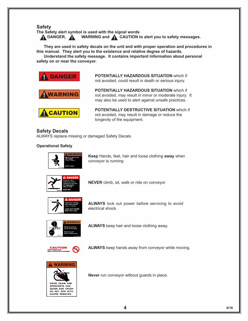
SafetyThe Safety alert symbol is used with the signal words DANGER, WARNING and CAUTION to alert you to safety messages. They are used in safety decals on the unit and with proper operation and procedures in this manual. They alert you to the existence and relative degree of hazards. Understand the safety message. It contains important information about personal safety on or near the conveyor.
POTENTIALLY HAZARDOUS SITUATION which if not avoided, could result in death or serious injury.
POTENTIALLY HAZARDOUS SITUATION which if not avoided, may result in minor or moderate injury. It may also be used to alert against unsafe practices.
POTENTIALLY DESTRUCTIVE SITUATION which if not avoided, may result in damage or reduce the longevity of the equipment.
Safety DecalsALWAYS replace missing or damaged Safety Decals.
Operational Safety
Never run conveyor without guards in place.
Keep Hands, feet, hair and loose clothing away when conveyor is running
ALWAYS lock out power before servicing to avoid electrical shock.
NEVER climb, sit, walk or ride on conveyor
ALWAYS keep hands away from conveyor while moving.
CAUTION!
DANGER!
WARNING!
ALWAYS keep hair and loose clothing away.
6/185
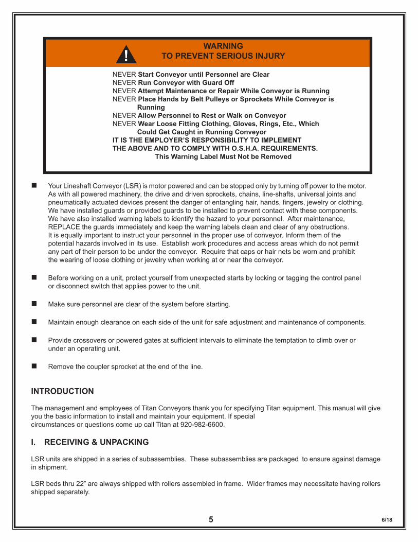
WARNINGTO PREVENT SERIOUS INJURY
NEVER Start Conveyor until Personnel are ClearNEVER Run Conveyor with Guard OffNEVER Attempt Maintenance or Repair While Conveyor is RunningNEVER Place Hands by Belt Pulleys or Sprockets While Conveyor is RunningNEVER Allow Personnel to Rest or Walk on ConveyorNEVER Wear Loose Fitting Clothing, Gloves, Rings, Etc., Which Could Get Caught in Running ConveyorIT IS THE EMPLOYER’S RESPONSIBILITY TO IMPLEMENT THE ABOVE AND TO COMPLY WITH O.S.H.A. REQUIREMENTS.
This Warning Label Must Not be Removed
n Your Lineshaft Conveyor (LSR) is motor powered and can be stopped only by turning off power to the motor. As with all powered machinery, the drive and driven sprockets, chains, line-shafts, universal joints and pneumatically actuated devices present the danger of entangling hair, hands, fingers, jewelry or clothing. We have installed guards or provided guards to be installed to prevent contact with these components. We have also installed warning labels to identify the hazard to your personnel. After maintenance, REPLACE the guards immediately and keep the warning labels clean and clear of any obstructions. It is equally important to instruct your personnel in the proper use of conveyor. Inform them of the potential hazards involved in its use. Establish work procedures and access areas which do not permit any part of their person to be under the conveyor. Require that caps or hair nets be worn and prohibit the wearing of loose clothing or jewelry when working at or near the conveyor.
n Before working on a unit, protect yourself from unexpected starts by locking or tagging the control panel or disconnect switch that applies power to the unit.
n Make sure personnel are clear of the system before starting.
n Maintain enough clearance on each side of the unit for safe adjustment and maintenance of components.
n Provide crossovers or powered gates at sufficient intervals to eliminate the temptation to climb over or under an operating unit.
n Remove the coupler sprocket at the end of the line.
INTRODUCTION
The management and employees of Titan Conveyors thank you for specifying Titan equipment. This manual will give you the basic information to install and maintain your equipment. If special circumstances or questions come up call Titan at 920-982-6600.
I. RECEIVING & UNPACKING
LSR units are shipped in a series of subassemblies. These subassemblies are packaged to ensure against damage in shipment.
LSR beds thru 22” are always shipped with rollers assembled in frame. Wider frames may necessitate having rollers shipped separately.
6/186
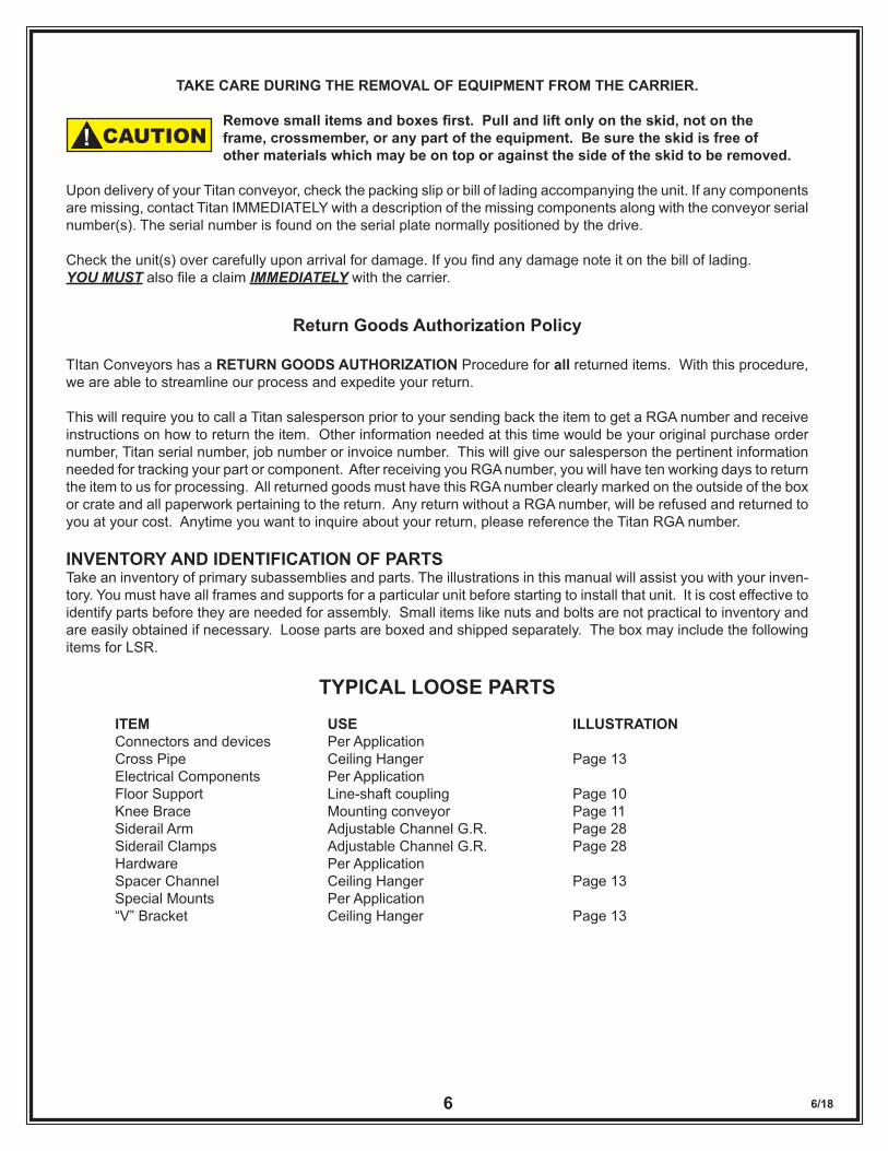
TAKE CARE DURING THE REMOVAL OF EQUIPMENT FROM THE CARRIER.
Removesmallitemsandboxesfirst.Pullandliftonlyontheskid,notonthe frame, crossmember, or any part of the equipment. Be sure the skid is free of other materials which may be on top or against the side of the skid to be removed. Upon delivery of your Titan conveyor, check the packing slip or bill of lading accompanying the unit. If any components are missing, contact Titan IMMEDIATELY with a description of the missing components along with the conveyor serial number(s). The serial number is found on the serial plate normally positioned by the drive.
Check the unit(s) over carefully upon arrival for damage. If you find any damage note it on the bill of lading. YOU MUST also file a claim IMMEDIATELY with the carrier.
Return Goods Authorization Policy
TItan Conveyors has a RETURN GOODS AUTHORIZATION Procedure for all returned items. With this procedure, we are able to streamline our process and expedite your return.
This will require you to call a Titan salesperson prior to your sending back the item to get a RGA number and receive instructions on how to return the item. Other information needed at this time would be your original purchase order number, Titan serial number, job number or invoice number. This will give our salesperson the pertinent information needed for tracking your part or component. After receiving you RGA number, you will have ten working days to return the item to us for processing. All returned goods must have this RGA number clearly marked on the outside of the box or crate and all paperwork pertaining to the return. Any return without a RGA number, will be refused and returned to you at your cost. Anytime you want to inquire about your return, please reference the Titan RGA number.
INVENTORY AND IDENTIFICATION OF PARTSTake an inventory of primary subassemblies and parts. The illustrations in this manual will assist you with your inven-tory. You must have all frames and supports for a particular unit before starting to install that unit. It is cost effective to identify parts before they are needed for assembly. Small items like nuts and bolts are not practical to inventory and are easily obtained if necessary. Loose parts are boxed and shipped separately. The box may include the following items for LSR.
TYPICAL LOOSE PARTSITEM USE ILLUSTRATIONConnectors and devices Per ApplicationCross Pipe Ceiling Hanger Page 13Electrical Components Per ApplicationFloor Support Line-shaft coupling Page 10Knee Brace Mounting conveyor Page 11Siderail Arm Adjustable Channel G.R. Page 28Siderail Clamps Adjustable Channel G.R. Page 28Hardware Per ApplicationSpacer Channel Ceiling Hanger Page 13Special Mounts Per Application“V” Bracket Ceiling Hanger Page 13
CAUTION!
6/187
II. INSTALLATION
WEAR SAFETY GLASSES, SAFETY SHOES, AND GLOVES.
HAVE AREA AROUND INSTALLATION SITE CLEARED OF DEBRIS.
LOCKOUT POWER TO CONVEYOR(S) UNTIL START-UP.
LOOK OUT FOR SHARP EDGES WHILE HANDLING CONVEYOR COMPONENTS.
BE CAREFUL IN AND AROUND THE CONVEYOR(S) DURING INSTALLATION. ALSO, BE AWARE OF OTHERS IN THE AREA.
ONLY ALLOW QUALIFIED PERSONNEL TO ASSEMBLE AND INSTALL CONVEYORS.
INTRODUCTION TO LINESHAFT CONVEYORSGENERAL
THIS SERVICE MANUAL IS INTENDED TO BE USED BY PERSONNEL WHO ARE KNOWLEDGEABLE OF SAFE WORKING CONDITIONS ON LIVE ROLLER CONVEYOR SYSTEMS.
Not all applications and components can possibly be covered; therefore, use this manual as a guide only. Specific questions relating to your conveyor should be addressed to your local Distributor. The Distributor is familiar with your specific system and can render immediate assistance if required.
Understand the WARNINGS at the beginning of this manual. Danger, Warnings and Cautions are included in ap-propriate places throughout this manual and are defined on pages 3 and 4 in this manual.
A thorough understanding and compliance with these Warnings and Cautions will greatly reduce the possibility of personnel injury and equipment damages.
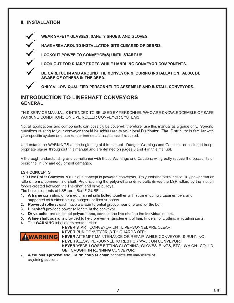
LSR CONCEPTSLSR Live Roller Conveyor is a unique concept in powered conveyors. Polyurethane belts individually power carrier rollers from a common line-shaft. Pretensioning the polyurethane drive belts drives the LSR rollers by the friction forces created between the line-shaft and drive pulleys. The basic elements of LSR are: See FIGURE 1.1. A frame consisting of formed channel rails bolted together with square tubing crossmembers and supported with either ceiling hangers or floor supports.2. Powered rollers: each have a circumferential groove near one end for the belt.3. Lineshaft provides power to length of the conveyor.4. Drive belts, pretensioned polyurethane, connect the line-shaft to the individual rollers.5. A line-shaft guard is provided to help prevent entanglement of hair, fingers or clothing in rotating parts.6. The WARNING label alerts personnel to: NEVER START CONVEYOR UNTIL PERSONNEL ARE CLEAR; NEVER RUN CONVEYOR WITH GUARDS OFF; NEVER ATTEMPT MAINTENANCE OR REPAIR WHILE CONVEYOR IS RUNNING; NEVER ALLOW PERSONNEL TO REST OR WALK ON CONVEYOR; NEVER WEAR LOOSE FITTING CLOTHING, GLOVES, RINGS, ETC., WHICH COULD GET CAUGHT IN RUNNING CONVEYOR;7. A coupler sprocket and Delrin coupler chain connects the line-shafts of adjoining sections.
WARNING!
6/188
Figure 1
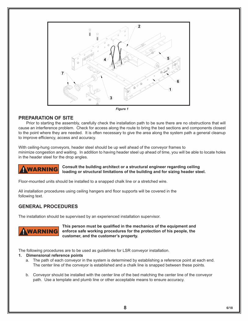
PREPARATION OF SITE Prior to starting the assembly, carefully check the installation path to be sure there are no obstructions that will cause an interference problem. Check for access along the route to bring the bed sections and components closest to the point where they are needed. It is often necessary to give the area along the system path a general cleanup to improve efficiency, access and accuracy.
With ceiling-hung conveyors, header steel should be up well ahead of the conveyor frames to minimize congestion and waiting. In addition to having header steel up ahead of time, you will be able to locate holes in the header steel for the drop angles.
Consult the building architect or a structural engineer regarding ceiling loading or structural limitations of the building and for sizing header steel.
Floor-mounted units should be installed to a snapped chalk line or a stretched wire.
All installation procedures using ceiling hangers and floor supports will be covered in the following text.
GENERAL PROCEDURES
The installation should be supervised by an experienced installation supervisor.
Thispersonmustbequalifiedinthemechanicsoftheequipmentand enforce safe working procedures for the protection of his people, the customer, and the customer’s property.
The following procedures are to be used as guidelines for LSR conveyor installation.1. Dimensional reference points a. The path of each conveyor in the system is determined by establishing a reference point at each end. The center line of the conveyor is established and a chalk line is snapped between these points.
b. Conveyor should be installed with the center line of the bed matching the center line of the conveyor path. Use a template and plumb line or other acceptable means to ensure accuracy.
WARNING!
WARNING!
1
2
3
4 5
WARNING
6
7
6/189
2. Elevations
a. All conveyors should be installed in accordance with the elevations shown on the layouts. In addition, all units must be level across the conveyor width.
b. After the first elevation is established at a critical point, the elevation of all other points shall be related to this first point. Dimension elevations from the floor at each point of support. As a system proceeds to an upper or lower floor, into another building or room, a new elevation will be dimensioned from the floor at that point. The new elevation will then become the reference for subsequent elevations. c. When installing an overhead system, the first end is dimensioned from the floor and becomes the elevation point until a change in elevation if shown in the layout. This new elevation is then dimensioned from the floor and becomes the new reference point. This process is repeated each time an elevation occurs.
SUPPORT ASSEMBLY
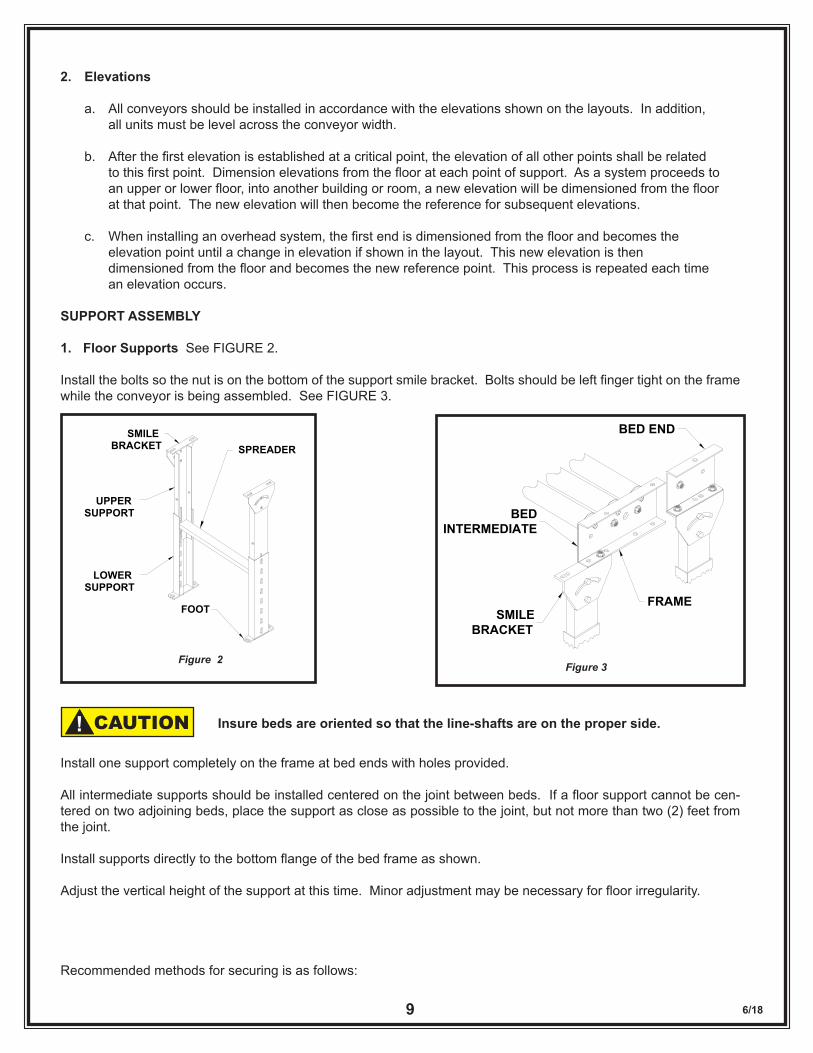
1. Floor Supports See FIGURE 2.
Install the bolts so the nut is on the bottom of the support smile bracket. Bolts should be left finger tight on the frame while the conveyor is being assembled. See FIGURE 3.
Install one support completely on the frame at bed ends with holes provided.
All intermediate supports should be installed centered on the joint between beds. If a floor support cannot be cen-tered on two adjoining beds, place the support as close as possible to the joint, but not more than two (2) feet from the joint.
Install supports directly to the bottom flange of the bed frame as shown.
Adjust the vertical height of the support at this time. Minor adjustment may be necessary for floor irregularity.
Recommended methods for securing is as follows:
Figure 2
SMILE BRACKET
UPPER SUPPORT
LOWER SUPPORT
SPREADER
FOOT
Insure beds are oriented so that the line-shafts are on the proper side.CAUTION!
BEDINTERMEDIATE
SMILEBRACKET
BED END
FRAME
Figure 3
6/1810
1. Concrete or Masonry Floors
a. Anchoring will be accomplished by drilling into the floor and inserting the suitable bolt anchor. b. Anchor all floor supports with minimum 3/8” diameter bolts, two staggered per floor support.
2. Wood Floors
Anchoring will be accomplished using suitable lag bolts. Lag bolt diameters should be the same as the bolt diameters used in concrete or masonry floors described above.
2. Knee Braces
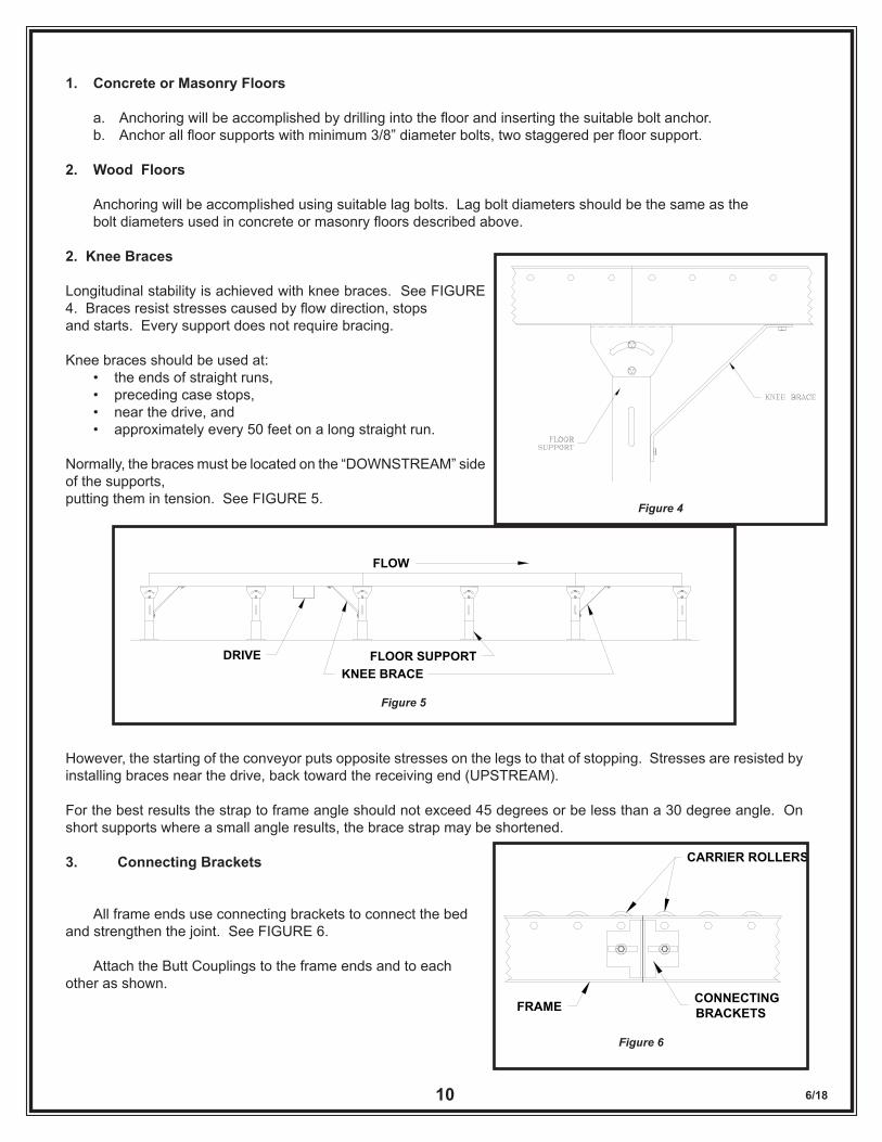
Longitudinal stability is achieved with knee braces. See FIGURE 4. Braces resist stresses caused by flow direction, stops and starts. Every support does not require bracing.
Knee braces should be used at: • the ends of straight runs, • preceding case stops, • near the drive, and • approximately every 50 feet on a long straight run.
Normally, the braces must be located on the “DOWNSTREAM” side of the supports, putting them in tension. See FIGURE 5.
However, the starting of the conveyor puts opposite stresses on the legs to that of stopping. Stresses are resisted by installing braces near the drive, back toward the receiving end (UPSTREAM).
For the best results the strap to frame angle should not exceed 45 degrees or be less than a 30 degree angle. On short supports where a small angle results, the brace strap may be shortened.
3. Connecting Brackets
All frame ends use connecting brackets to connect the bed and strengthen the joint. See FIGURE 6.
Attach the Butt Couplings to the frame ends and to each other as shown.
Figure 4
FLOW
DRIVE FLOOR SUPPORTKNEE BRACE
Figure 5
Figure 6
CARRIER ROLLERS
CONNECTINGBRACKETSFRAME
6/1811
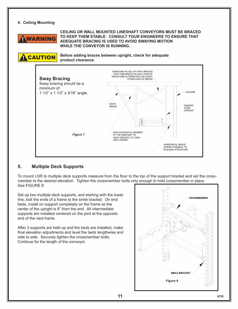
4. Ceiling Mounting
CEILING OR WALL MOUNTED LINESHAFT CONVEYORS MUST BE BRACED TO KEEP THEM STABLE. CONSULT YOUR ENGINEERS TO ENSURE THAT ADEQUATE BRACING IS USED TO AVOID SWAYING MOTION WHILE THE CONVEYOR IS RUNNING.
Before adding braces between upright, check for adequate product clearance.
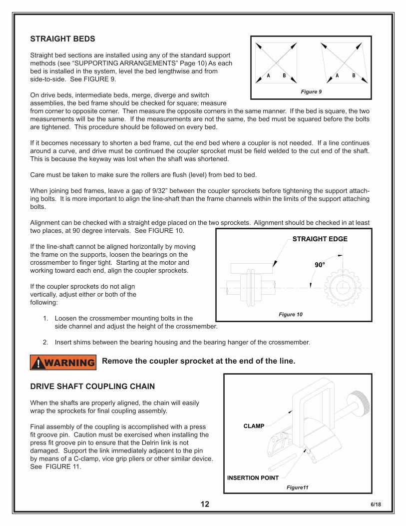
5. Multiple Deck Supports
To mount LSR to multiple deck supports measure from the floor to the top of the support bracket and set the cross-member to the desired elevation. Tighten the crossmember bolts only enough to hold crossmember in place. See FIGURE 8.
Set up two multiple deck supports, and starting with the lower line, bolt the ends of a frame to the smile bracket. On end beds, install on support completely on the frame so the center of the upright is 6” from the end. All intermediate supports are installed centered on the joint at the opposite end of the next frame.
After 3 supports are held up and the beds are installed, make final elevation adjustments and level the beds lengthwise and side to side. Securely tighten the crossmember bolts. Continue for the length of the conveyor.
Figure 7
COLUMN
HANGERSTEELUPRIGHT
HORIZONTAL BRACEWHERE POSSIBLE TO BUILDING STRUCTURE
ADD HORIZONTAL MEMBER AT THE MIDPOINT TO
AND LONGER
SWAYBRACE
X-BRACING IN LIEU OF SWAY BRACESWITH ONE BRACE ON EACH PAIR OF
DROPS AND ALTERNATING ON EVERYOTHER PAIR OF DROPS
SWAY BRACES 12" LONG
Sway BracingSway bracing should be a minimum of 1 1/2” x 1 1/2” x 3/16” angle.
CAUTION!
WARNING!
CROSSMEMBER
SMILE BRACKET
Figure 8
6/1812
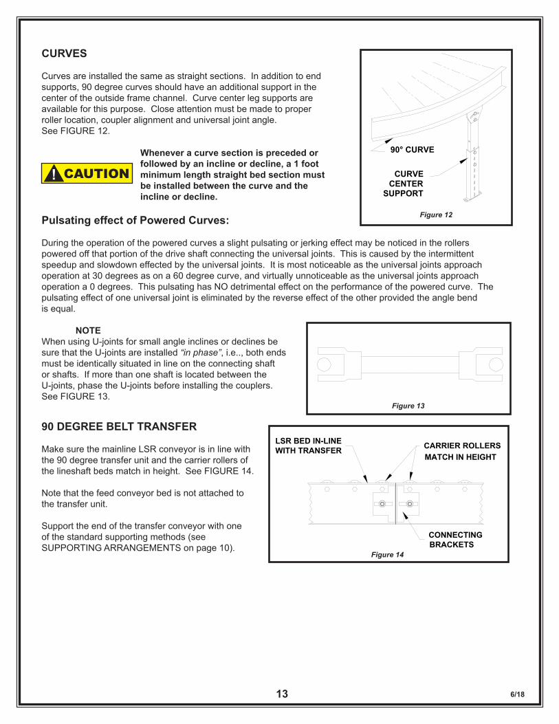
STRAIGHT BEDS
Straight bed sections are installed using any of the standard support methods (see “SUPPORTING ARRANGEMENTS” Page 10) As each bed is installed in the system, level the bed lengthwise and from side-to-side. See FIGURE 9.
On drive beds, intermediate beds, merge, diverge and switch assemblies, the bed frame should be checked for square; measure from corner to opposite corner. Then measure the opposite corners in the same manner. If the bed is square, the two measurements will be the same. If the measurements are not the same, the bed must be squared before the bolts are tightened. This procedure should be followed on every bed.
If it becomes necessary to shorten a bed frame, cut the end bed where a coupler is not needed. If a line continues around a curve, and drive must be continued the coupler sprocket must be field welded to the cut end of the shaft. This is because the keyway was lost when the shaft was shortened.
Care must be taken to make sure the rollers are flush (level) from bed to bed.
When joining bed frames, leave a gap of 9/32” between the coupler sprockets before tightening the support attach-ing bolts. It is more important to align the line-shaft than the frame channels within the limits of the support attaching bolts.
Alignment can be checked with a straight edge placed on the two sprockets. Alignment should be checked in at least two places, at 90 degree intervals. See FIGURE 10.
If the line-shaft cannot be aligned horizontally by moving the frame on the supports, loosen the bearings on the crossmember to finger tight. Starting at the motor and working toward each end, align the coupler sprockets.
If the coupler sprockets do not align vertically, adjust either or both of the following:
1. Loosen the crossmember mounting bolts in the side channel and adjust the height of the crossmember.
2. Insert shims between the bearing housing and the bearing hanger of the crossmember.
Remove the coupler sprocket at the end of the line.
DRIVE SHAFT COUPLING CHAIN
When the shafts are properly aligned, the chain will easily wrap the sprockets for final coupling assembly.
Final assembly of the coupling is accomplished with a press fit groove pin. Caution must be exercised when installing the press fit groove pin to ensure that the Delrin link is not damaged. Support the link immediately adjacent to the pin by means of a C-clamp, vice grip pliers or other similar device.See FIGURE 11.
A B A B
Figure 9
90°
STRAIGHT EDGE
Figure 10
WARNING!
CLAMP
INSERTION POINTFigure11
6/1813
CURVES
Curves are installed the same as straight sections. In addition to end supports, 90 degree curves should have an additional support in the center of the outside frame channel. Curve center leg supports are available for this purpose. Close attention must be made to proper roller location, coupler alignment and universal joint angle. See FIGURE 12.
Whenever a curve section is preceded or followed by an incline or decline, a 1 foot minimum length straight bed section must be installed between the curve and the incline or decline.
Pulsating effect of Powered Curves:
During the operation of the powered curves a slight pulsating or jerking effect may be noticed in the rollers powered off that portion of the drive shaft connecting the universal joints. This is caused by the intermittent speedup and slowdown effected by the universal joints. It is most noticeable as the universal joints approach operation at 30 degrees as on a 60 degree curve, and virtually unnoticeable as the universal joints approach operation a 0 degrees. This pulsating has NO detrimental effect on the performance of the powered curve. The pulsating effect of one universal joint is eliminated by the reverse effect of the other provided the angle bend is equal.
NOTEWhen using U-joints for small angle inclines or declines be sure that the U-joints are installed “in phase”, i.e.., both ends must be identically situated in line on the connecting shaft or shafts. If more than one shaft is located between the U-joints, phase the U-joints before installing the couplers. See FIGURE 13.
90 DEGREE BELT TRANSFER
Make sure the mainline LSR conveyor is in line with the 90 degree transfer unit and the carrier rollers of the lineshaft beds match in height. See FIGURE 14.
Note that the feed conveyor bed is not attached to the transfer unit.
Support the end of the transfer conveyor with one of the standard supporting methods (see SUPPORTING ARRANGEMENTS on page 10).
90° CURVE
CURVECENTER
SUPPORT
Figure 12
Figure 13
CAUTION!
CARRIER ROLLERS
CONNECTINGBRACKETS
MATCH IN HEIGHT
LSR BED IN-LINEWITH TRANSFER
Figure 14
6/1814
Leave a 1/4” gap between the end of the transfer conveyor and the side channel of the mainline of the LSR conveyor. See FIGURE 15.
The Transfer Belts in the up position should match the height of the rollers in the transfer line. See FIGURE 16.
Attach the air supply line to the brass air fitting. To properly seat the air line into the fitting, observe the following procedure:
1. Insure the end of the air line is cut square. 2. Insert the end of the air line on the barbed brass fitting until snug. 3. Adjust flow control for smooth operation.
For proper operation, maintain air pressure between 50 and 60 pounds of air pressure at the transfer.
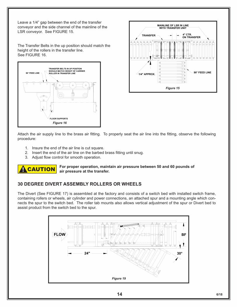
30 DEGREE DIVERT ASSEMBLY ROLLERS OR WHEELS
The Divert (See FIGURE 17) is assembled at the factory and consists of a switch bed with installed switch frame, containing rollers or wheels, air cylinder and power connections, an attached spur and a mounting angle which con-nects the spur to the switch bed. The roller tab mounts also allows vertical adjustment of the spur or Divert bed to assist product from the switch bed to the spur.
0"
MAINLINE OF LSR IN LINEWITH TRANSFER UNIT
TRANSFER
1/4" APPROX. 90° FEED LINE
4" CTR.ON TRANSFER
Figure 15
Figure 16FLOOR SUPPORTS
TRANSFER BELTS IN UP POSITIONSHOULD MATCH HEIGHT OF CARRIERROLLER IN TRANSFER LINE90° FEED LINE
CAUTION!
BF
30°24"
FLOW
Figure 19
6/1815
The Divert assembly is installed in the conveyor system using any of the standard supporting arrangements.
After the Divert assembly is installed and the line-shaft coupler sprockets are connected, install line-shaft guard to all exposed sections of line-shaft. (See “Safety Guard” section Page 27).
For proper operation, use a minimum of 60 psi air pressure at the switch cylinder.
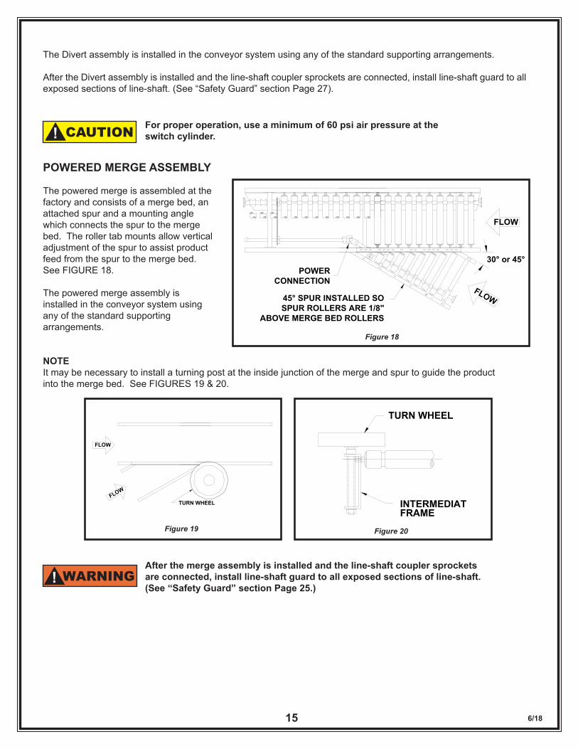
POWERED MERGE ASSEMBLY
The powered merge is assembled at the factory and consists of a merge bed, an attached spur and a mounting angle which connects the spur to the merge bed. The roller tab mounts allow vertical adjustment of the spur to assist product feed from the spur to the merge bed. See FIGURE 18.
The powered merge assembly is installed in the conveyor system using any of the standard supporting arrangements.
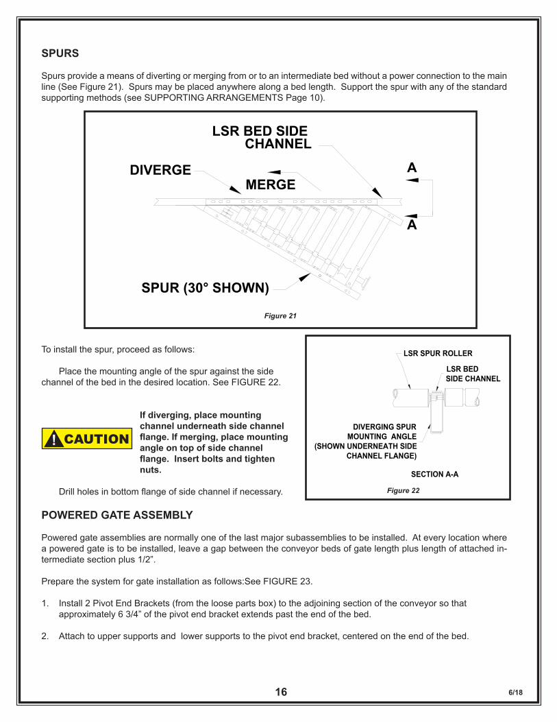
NOTEIt may be necessary to install a turning post at the inside junction of the merge and spur to guide the product into the merge bed. See FIGURES 19 & 20.
After the merge assembly is installed and the line-shaft coupler sprockets are connected, install line-shaft guard to all exposed sections of line-shaft. (See “Safety Guard” section Page 25.)
CAUTION!
30° or 45°
FLOW
FLOW
POWERCONNECTION
45° SPUR INSTALLED SO SPUR ROLLERS ARE 1/8"
ABOVE MERGE BED ROLLERS
Figure 18
FLOW
FLOW
TURN WHEEL
Figure 19
INTERMEDIATE FRAME
TURN WHEEL
Figure 20
WARNING!
6/1816
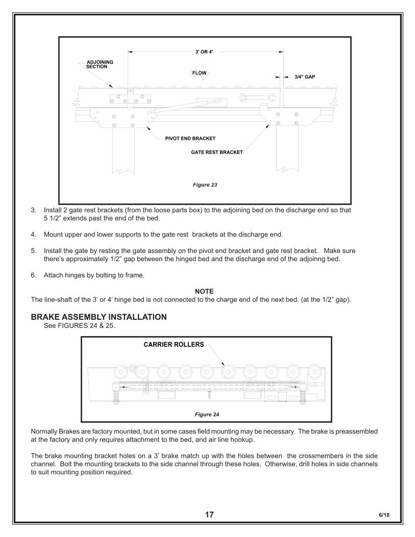
SPURS
Spurs provide a means of diverting or merging from or to an intermediate bed without a power connection to the main line (See Figure 21). Spurs may be placed anywhere along a bed length. Support the spur with any of the standard supporting methods (see SUPPORTING ARRANGEMENTS Page 10).
To install the spur, proceed as follows:
Place the mounting angle of the spur against the side channel of the bed in the desired location. See FIGURE 22.
If diverging, place mounting channel underneath side channel flange.Ifmerging,placemounting angle on top of side channel flange.Insertboltsandtighten nuts.
Drill holes in bottom flange of side channel if necessary.
POWERED GATE ASSEMBLY
Powered gate assemblies are normally one of the last major subassemblies to be installed. At every location where a powered gate is to be installed, leave a gap between the conveyor beds of gate length plus length of attached in-termediate section plus 1/2”.
Prepare the system for gate installation as follows:See FIGURE 23.
1. Install 2 Pivot End Brackets (from the loose parts box) to the adjoining section of the conveyor so that approximately 6 3/4” of the pivot end bracket extends past the end of the bed.
2. Attach to upper supports and lower supports to the pivot end bracket, centered on the end of the bed.
Figure 21
DIVERGE
LSR BED SIDE CHANNEL
SPUR (30° SHOWN)
MERGEA
A
Figure 22
LSR SPUR ROLLER
LSR BED SIDE CHANNEL
DIVERGING SPURMOUNTING ANGLE
(SHOWN UNDERNEATH SIDECHANNEL FLANGE)
SECTION A-A
CAUTION!
6/1817
3. Install 2 gate rest brackets (from the loose parts box) to the adjoining bed on the discharge end so that 5 1/2” extends past the end of the bed.
4. Mount upper and lower supports to the gate rest brackets at the discharge end.
5. Install the gate by resting the gate assembly on the pivot end bracket and gate rest bracket. Make sure there’s approximately 1/2” gap between the hinged bed and the discharge end of the adjoinng bed.
6. Attach hinges by bolting to frame.
NOTEThe line-shaft of the 3’ or 4’ hinge bed is not connected to the charge end of the next bed. (at the 1/2” gap).
BRAKE ASSEMBLY INSTALLATION See FIGURES 24 & 25.
Normally Brakes are factory mounted, but in some cases field mounting may be necessary. The brake is preassembled at the factory and only requires attachment to the bed, and air line hookup.
The brake mounting bracket holes on a 3’ brake match up with the holes between the crossmembers in the side channel. Bolt the mounting brackets to the side channel through these holes. Otherwise, drill holes in side channels to suit mounting position required.
Figure 23
3' OR 4'
3/4" GAP
SECTIONADJOINING
PIVOT END BRACKET
GATE REST BRACKET
FLOW
CARRIER ROLLERS
Figure 24
6/1818
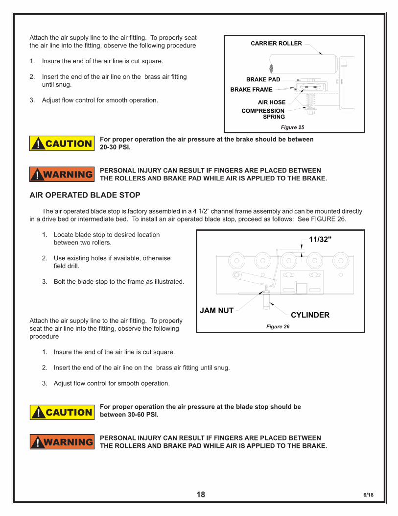
Attach the air supply line to the air fitting. To properly seat the air line into the fitting, observe the following procedure
1. Insure the end of the air line is cut square.
2. Insert the end of the air line on the brass air fitting until snug.
3. Adjust flow control for smooth operation.
For proper operation the air pressure at the brake should be between 20-30 PSI.
PERSONAL INJURY CAN RESULT IF FINGERS ARE PLACED BETWEEN THE ROLLERS AND BRAKE PAD WHILE AIR IS APPLIED TO THE BRAKE.
AIR OPERATED BLADE STOP
The air operated blade stop is factory assembled in a 4 1/2” channel frame assembly and can be mounted directly in a drive bed or intermediate bed. To install an air operated blade stop, proceed as follows: See FIGURE 26.
1. Locate blade stop to desired location between two rollers.
2. Use existing holes if available, otherwise field drill.
3. Bolt the blade stop to the frame as illustrated.
Attach the air supply line to the air fitting. To properly seat the air line into the fitting, observe the following procedure
1. Insure the end of the air line is cut square.
2. Insert the end of the air line on the brass air fitting until snug.
3. Adjust flow control for smooth operation.
For proper operation the air pressure at the blade stop should be between 30-60 PSI.
PERSONAL INJURY CAN RESULT IF FINGERS ARE PLACED BETWEEN THE ROLLERS AND BRAKE PAD WHILE AIR IS APPLIED TO THE BRAKE.
BRAKE PAD
CARRIER ROLLER
BRAKE FRAME
AIR HOSECOMPRESSION
SPRING
Figure 25
CAUTION!
WARNING!
11/32"
JAM NUT CYLINDERFigure 26
CAUTION!
WARNING!
6/1819
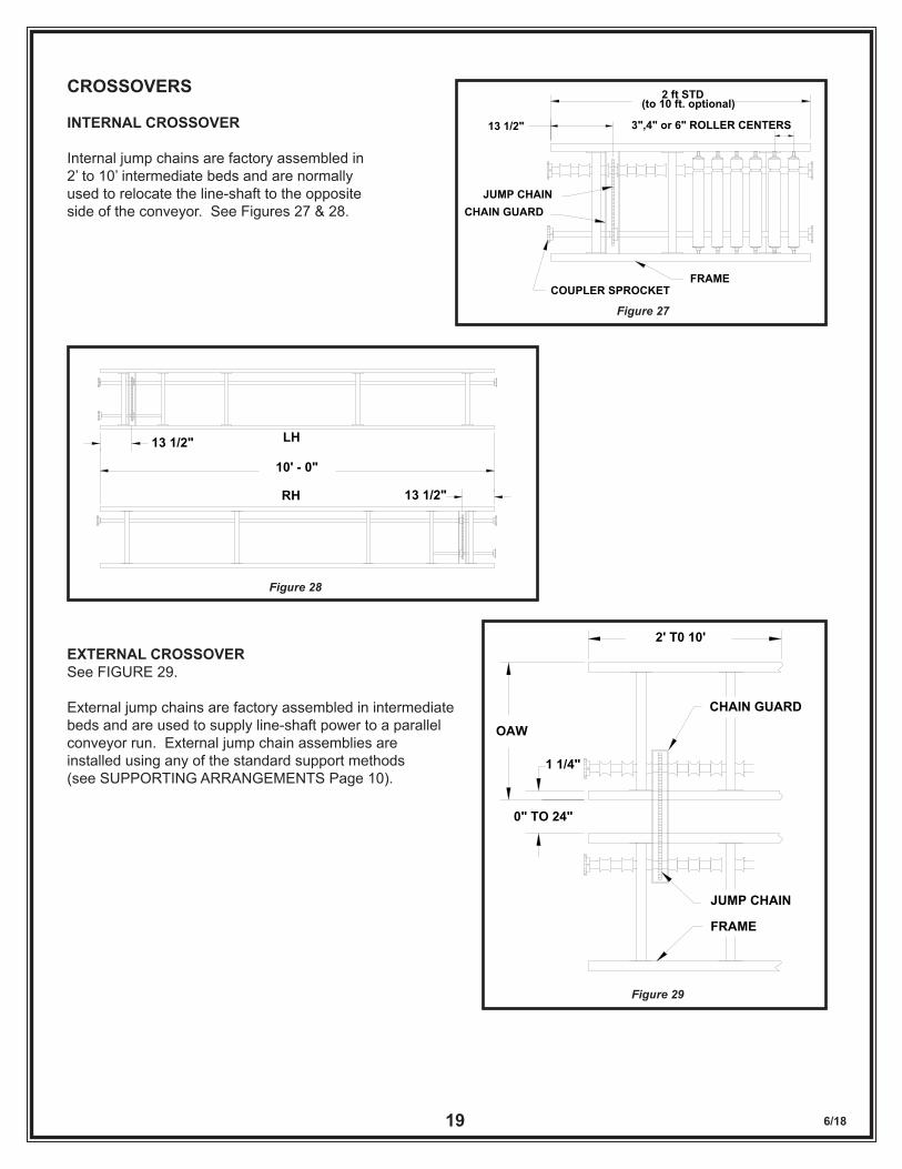
CROSSOVERS
INTERNAL CROSSOVER
Internal jump chains are factory assembled in 2’ to 10’ intermediate beds and are normally used to relocate the line-shaft to the opposite side of the conveyor. See Figures 27 & 28.
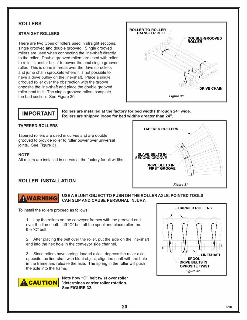
EXTERNAL CROSSOVERSee FIGURE 29.
External jump chains are factory assembled in intermediate beds and are used to supply line-shaft power to a parallel conveyor run. External jump chain assemblies are installed using any of the standard support methods (see SUPPORTING ARRANGEMENTS Page 10).
2 ft STD(to 10 ft. optional)
JUMP CHAINCHAIN GUARD
COUPLER SPROCKETFRAME
3",4" or 6" ROLLER CENTERS13 1/2"
Figure 27
13 1/2" LH
RH
10' - 0"
13 1/2"
Figure 28
2' T0 10'
1 1/4"
0" TO 24"
OAW
CHAIN GUARD
JUMP CHAIN
FRAME
Figure 29
6/1820
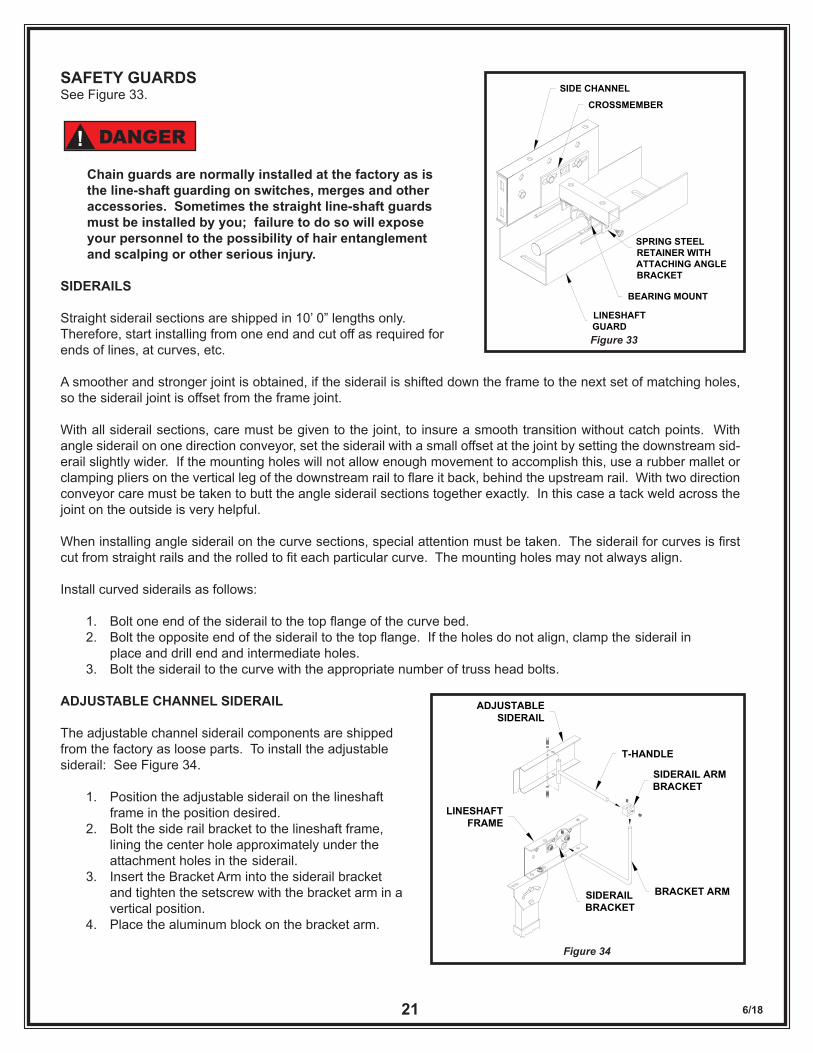
ROLLERS
STRAIGHT ROLLERS
There are two types of rollers used in straight sections, single grooved and double grooved. Single grooved rollers are used when connecting the line-shaft directly to the roller. Double grooved rollers are used with roller to roller “transfer belts” to power the next single grooved roller. This is done in areas over the drive sprockets and jump chain sprockets where it is not possible to have a drive pulley on the line-shaft. Place a single grooved roller over the obstruction with the groove opposite the line-shaft and place the double grooved roller next to it. The single grooved rollers complete the bed section. See Figure 30.
Rollers are installed at the factory for bed widths through 24” wide. Rollers are shipped loose for bed widths greater than 24”.
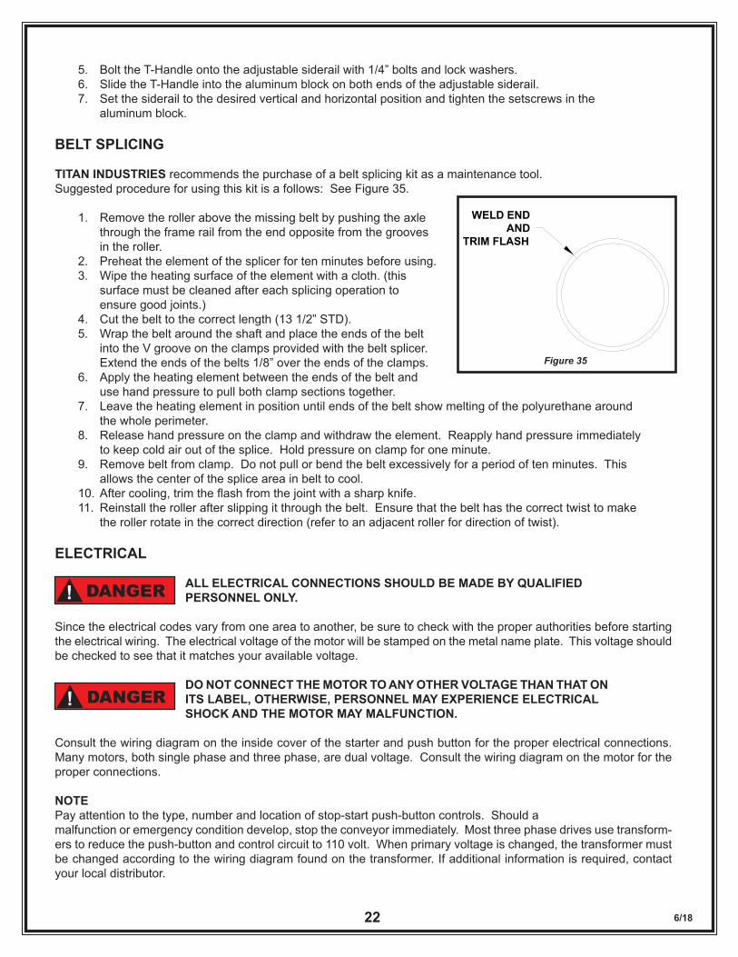
TAPERED ROLLERS
Tapered rollers are used in curves and are double grooved to provide roller to roller power over universal joints. See Figure 31.
NOTEAll rollers are installed in curves at the factory for all widths.
ROLLER INSTALLATION
USE A BLUNT OBJECT TO PUSH ON THE ROLLER AXLE. POINTED TOOLS CAN SLIP AND CAUSE PERSONAL INJURY.
To install the rollers proceed as follows:
1. Lay the rollers on the conveyor frames with the grooved end over the line-shaft. Lift “O” belt off the spool and place roller thru the “O” belt.
2. After placing the belt over the roller, put the axle on the line-shaft end into the hex hole in the conveyor side channel.
3. Since rollers have spring loaded axles, depress the roller axle opposite the line-shaft with blunt object, align the shaft with the hole in the frame and release the axle. The spring in the roller will push the axle into the frame.
Note how “O” belt twist over roller `determines carrier roller rotation. See FIGURE 32.
IMPORTANT
TAPERED ROLLERS
DRIVE BELTS IN FIRST GROOVE
SLAVE BELTS INSECOND GROOVE
Figure 31
Figure 30
ROLLER-TO-ROLLERTRANSFER BELT
DOUBLE-GROOVEDROLLER
DRIVE CHAIN
WARNING!
Figure 32
CARRIER ROLLERS
LINESHAFTSPOOL
DRIVE BELTS INOPPOSITE TWIST
CAUTION!
6/1821
SAFETY GUARDSSee Figure 33.
Chain guards are normally installed at the factory as is the line-shaft guarding on switches, merges and other accessories. Sometimes the straight line-shaft guards must be installed by you; failure to do so will expose your personnel to the possibility of hair entanglement and scalping or other serious injury.
SIDERAILS
Straight siderail sections are shipped in 10’ 0” lengths only. Therefore, start installing from one end and cut off as required for ends of lines, at curves, etc.
A smoother and stronger joint is obtained, if the siderail is shifted down the frame to the next set of matching holes, so the siderail joint is offset from the frame joint.
With all siderail sections, care must be given to the joint, to insure a smooth transition without catch points. With angle siderail on one direction conveyor, set the siderail with a small offset at the joint by setting the downstream sid-erail slightly wider. If the mounting holes will not allow enough movement to accomplish this, use a rubber mallet or clamping pliers on the vertical leg of the downstream rail to flare it back, behind the upstream rail. With two direction conveyor care must be taken to butt the angle siderail sections together exactly. In this case a tack weld across the joint on the outside is very helpful.
When installing angle siderail on the curve sections, special attention must be taken. The siderail for curves is first cut from straight rails and the rolled to fit each particular curve. The mounting holes may not always align.
Install curved siderails as follows:
1. Bolt one end of the siderail to the top flange of the curve bed. 2. Bolt the opposite end of the siderail to the top flange. If the holes do not align, clamp the siderail in place and drill end and intermediate holes. 3. Bolt the siderail to the curve with the appropriate number of truss head bolts.
ADJUSTABLE CHANNEL SIDERAIL
The adjustable channel siderail components are shipped from the factory as loose parts. To install the adjustable siderail: See Figure 34.
1. Position the adjustable siderail on the lineshaft frame in the position desired. 2. Bolt the side rail bracket to the lineshaft frame, lining the center hole approximately under the attachment holes in the siderail. 3. Insert the Bracket Arm into the siderail bracket and tighten the setscrew with the bracket arm in a vertical position. 4. Place the aluminum block on the bracket arm.
CROSSMEMBER
SIDE CHANNEL
SPRING STEEL RETAINER WITHATTACHING ANGLE BRACKET
BEARING MOUNT
LINESHAFTGUARDFigure 33
DANGER!
Figure 34
T-HANDLE
ADJUSTABLE SIDERAIL
BRACKET ARMSIDERAILBRACKET
LINESHAFTFRAME
SIDERAIL ARMBRACKET
6/1822
5. Bolt the T-Handle onto the adjustable siderail with 1/4” bolts and lock washers. 6. Slide the T-Handle into the aluminum block on both ends of the adjustable siderail. 7. Set the siderail to the desired vertical and horizontal position and tighten the setscrews in the aluminum block.
BELT SPLICING
TITAN INDUSTRIES recommends the purchase of a belt splicing kit as a maintenance tool.Suggested procedure for using this kit is a follows: See Figure 35.
1. Remove the roller above the missing belt by pushing the axle through the frame rail from the end opposite from the grooves in the roller. 2. Preheat the element of the splicer for ten minutes before using. 3. Wipe the heating surface of the element with a cloth. (this surface must be cleaned after each splicing operation to ensure good joints.) 4. Cut the belt to the correct length (13 1/2” STD). 5. Wrap the belt around the shaft and place the ends of the belt into the V groove on the clamps provided with the belt splicer. Extend the ends of the belts 1/8” over the ends of the clamps. 6. Apply the heating element between the ends of the belt and use hand pressure to pull both clamp sections together. 7. Leave the heating element in position until ends of the belt show melting of the polyurethane around the whole perimeter. 8. Release hand pressure on the clamp and withdraw the element. Reapply hand pressure immediately to keep cold air out of the splice. Hold pressure on clamp for one minute. 9. Remove belt from clamp. Do not pull or bend the belt excessively for a period of ten minutes. This allows the center of the splice area in belt to cool. 10. After cooling, trim the flash from the joint with a sharp knife. 11. Reinstall the roller after slipping it through the belt. Ensure that the belt has the correct twist to make the roller rotate in the correct direction (refer to an adjacent roller for direction of twist).
ELECTRICAL
ALL ELECTRICAL CONNECTIONS SHOULD BE MADE BY QUALIFIED PERSONNEL ONLY.
Since the electrical codes vary from one area to another, be sure to check with the proper authorities before starting the electrical wiring. The electrical voltage of the motor will be stamped on the metal name plate. This voltage should be checked to see that it matches your available voltage.
DO NOT CONNECT THE MOTOR TO ANY OTHER VOLTAGE THAN THAT ON ITS LABEL, OTHERWISE, PERSONNEL MAY EXPERIENCE ELECTRICAL SHOCK AND THE MOTOR MAY MALFUNCTION.
Consult the wiring diagram on the inside cover of the starter and push button for the proper electrical connections. Many motors, both single phase and three phase, are dual voltage. Consult the wiring diagram on the motor for the proper connections.
NOTEPay attention to the type, number and location of stop-start push-button controls. Should a malfunction or emergency condition develop, stop the conveyor immediately. Most three phase drives use transform-ers to reduce the push-button and control circuit to 110 volt. When primary voltage is changed, the transformer must be changed according to the wiring diagram found on the transformer. If additional information is required, contact your local distributor.
WELD ENDAND
TRIM FLASH
Figure 35
DANGER!
DANGER!
6/1823
FINAL ASSEMBLY CHECK
At the final checkout time the unit should be completely installed. This means the unit should be in position with the siderail, line-shaft guard, etc. installed, and all electrical and pneumatic connection made.
At this time check elevations. The conveyor should be level from side to side and from end to end except at designated incline or decline areas.
All nuts, bolts and fasteners must be checked for security.
All electrical connections and wiring and any air fittings and lines should be checked for security and proper routing.
COMMISSIONING
This phase of the project is known by different descriptions\: run-in, commissioning, debug, etc. This is where the finishing touches are applied, and the unforeseen considerations corrected. During these test runs or preliminary operating runs, the following items will be checked:
Security of all bolted connections and set screws.
The functioning of the electrical controls.
Proper travel direction (belt twist) of all rollers.
Adequate clearances for product (siderail, bracing, etc.).
Proper adjustment and lack of hang-up points of all siderails.
Simulation of all operational functions with actual product.
III. MAINTENANCE
MOTORS 1. CLEANING - All motors should be kept free of dirt and grease accumulations. Open motors should be periodically vacuumed to remove dust and dirt from the windings.
2. VENTILATION - For best results motors should be operated in an area where adequate ventilation is available.
3. TEMPERATURE - Most of todays smooth body T.E.N.V. and T.E.F.C. Motors run hot to the touch. As long as ambient temperatures are not exceeded, and more importantly, ampere draw is within the allowable range, there should be no need to worry. (Both of these limits are found on the motor nameplate.)
4. LUBRICATION - Most electric motors are lubricated for life and under normal conditions require no more lubrication. Under severe conditions where additional lubrication is required, use the following chart as a guide.
THE FOLLOWING CHART IS BASED ON MOTORS WITH GREASE LUBRICATED BEARINGS, RUNNING AT SPEEDS OF 1750 R.P.M. OR LESS, AND OPERATING WITHIN AN AMBIENT TEMPERATURE RANGE OF BETWEEN 0 DEGREES F. TO 120 DEGREES F.
CAUTION!
6/1824
CONDITION LUBRICATING FREQUENCY
Normal 8 hr. dayLight Loads 2 to 3 years
Heavy 24 hr. DayHeavy Loads
Dirty Conditions1 Year
ExtremeShock Loads
High Temperatures3 to 6 Months
Typical lubricants that can be used: Chevron Oil Co. - SRI#2 GulfRefiningCo.-Precision#2or#3 Shell Oil Co. - Alvania #2, Dolium R Mobile Oil Co. - Mobilux Grease #2 Texaco Inc. - Premium RB SinclairRefiningCo.-A.F.#2
REDUCERS
The following reducer information is concerned primarily with wormgear reducers. If your conveyor is equipped with another type, refer to the manufacturer’s recommendations for installation and maintenance sent along at time of shipment.
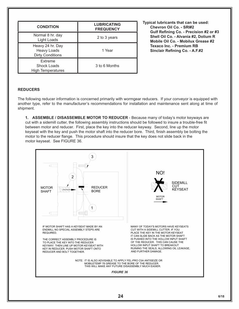
1. ASSEMBLE / DISASSEMBLE MOTOR TO REDUCER - Because many of today’s motor keyways are cut with a sidemill cutter, the following assembly instructions should be followed to insure a trouble-free fit between motor and reducer. First, place the key into the reducer keyway. Second, line up the motor keyseat with the key and push the motor shaft into the reducer bore. Third, finish assembly be bolting the motor to the reducer flange. This procedure should insure that the key does not slide back in the motor keyseat. See FIGURE 36.
FIGURE 36
SIDEMILLMOTOR SHAFT BORE
REDUCER KEYSEATCUT
MOTOR SHAFT
1
2
3
NO!
IF MOTOR SHAFT HAS A KEYSEAT MADE BY AN ENDMILL NO SPECIAL ASSEMBLY STEPS ARE REQUIRED.
THE CORRECT ASSEMBLY PROCEDURE IS TO PLACE THE KEY INTO THE REDUCER KEYWAY. THEN LINE UP MOTOR KEYSEAT WITHKEY IN REDUCER. PUSH MOTOR SHAFT ONTOREDUCER AND BOLT TOGETHER.
MANY OF TODAY'S MOTORS HAVE KEYSEATSCUT WITH A SIDEMILL CUTTER. IF YOU PLACE THE KEY IN THE MOTOR KEYSEAT IT CAN SLIDE BACK AS THE MOTOR SHAFT IS PUSHED INTO THE HOLLOW INPUT SHAFTOF THE REDUCER. THIS CAN CAUSE THE HOLLOW INPUT SHAFT TO BREAKOUT RUINING THE SEALS, ALLOWING OIL LEAKAGE,AND FURTHER DAMAGE.
NOTE: IT IS ALSO ADVISABLE TO APPLY FEL-PRO C5A ANTISEIZE OR
THIS WILL MAKE ANY FUTURE DISASSEMBLY MUCH EASIER. MOBILETEMP 78 GREASE TO THE BORE OF THE REDUCER.
6/1825
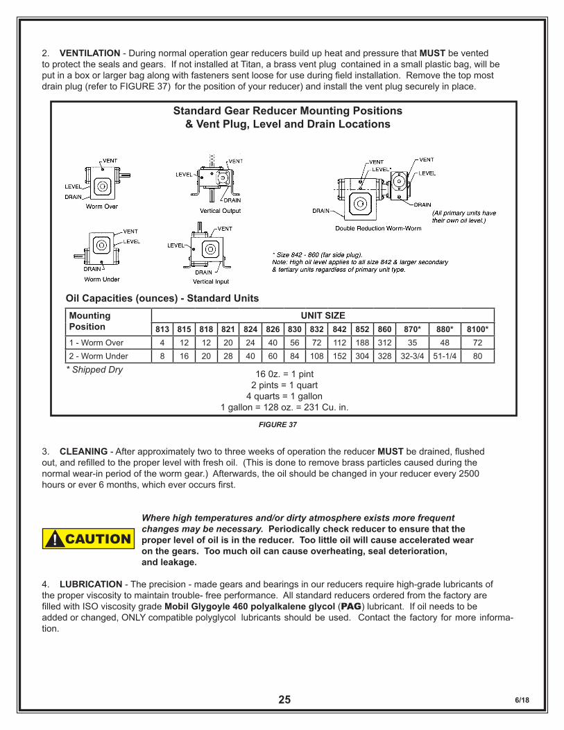
2. VENTILATION - During normal operation gear reducers build up heat and pressure that MUST be vented to protect the seals and gears. If not installed at Titan, a brass vent plug contained in a small plastic bag, will be put in a box or larger bag along with fasteners sent loose for use during field installation. Remove the top most drain plug (refer to FIGURE 37) for the position of your reducer) and install the vent plug securely in place.
3. CLEANING - After approximately two to three weeks of operation the reducer MUST be drained, flushed out, and refilled to the proper level with fresh oil. (This is done to remove brass particles caused during the normal wear-in period of the worm gear.) Afterwards, the oil should be changed in your reducer every 2500 hours or ever 6 months, which ever occurs first.
Where high temperatures and/or dirty atmosphere exists more frequent changes may be necessary. Periodically check reducer to ensure that the proper level of oil is in the reducer. Too little oil will cause accelerated wear on the gears. Too much oil can cause overheating, seal deterioration, and leakage.
4. LUBRICATION - The precision - made gears and bearings in our reducers require high-grade lubricants of the proper viscosity to maintain trouble- free performance. All standard reducers ordered from the factory are filled with ISO viscosity grade Mobil Glygoyle 460 polyalkalene glycol (PAG) lubricant. If oil needs to be added or changed, ONLY compatible polyglycol lubricants should be used. Contact the factory for more informa-tion.
Mounting Position
UNIT SIZE813 815 818 821 824 826 830 832 842 852 860 870* 880* 8100*
1 - Worm Over 4 12 12 20 24 40 56 72 112 188 312 35 48 722 - Worm Under 8 16 20 28 40 60 84 108 152 304 328 32-3/4 51-1/4 80
Oil Capacities (ounces) - Standard Units
* Shipped Dry 16 0z. = 1 pint2 pints = 1 quart
4 quarts = 1 gallon1 gallon = 128 oz. = 231 Cu. in.
Standard Gear Reducer Mounting Positions& Vent Plug, Level and Drain Locations
FIGURE 37
CAUTION!
6/1826
5. TEMPERATURE - Most Titan Units are supplied with wormgear reducers. These units may run at temperatures between 100 degrees to 200 degrees F. (Higher temperatures are especially common during start up). There is NO NEED TO WORRY unless temperatures exceed 200 degrees F.
6. GENERAL MAINTENANCE - Regular inspection to insure the reducer bolts and screws are tight, correct alignment of shaft and/or coupling, no major oil leaks, no excessive heating and no unusual vibration or noise will insure maximum life and performance of the reducer.
BEARINGS
All bearings used in LSR (except U-joints) are sealed for life and do not require lubrication. If a defective roller bearing is found, replace the roller. All U-joint bearings require general purpose greasing every month or more fre-quently as required by operating conditions.
CHAIN & SPROCKETS
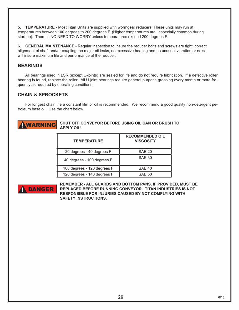
For longest chain life a constant film or oil is recommended. We recommend a good quality non-detergent pe-troleum base oil. Use the chart below
SHUT OFF CONVEYOR BEFORE USING OIL CAN OR BRUSH TO APPLY OIL!
REMEMBER - ALL GUARDS AND BOTTOM PANS, IF PROVIDED, MUST BE REPLACED BEFORE RUNNING CONVEYOR. TITAN INDUSTRIES IS NOT RESPONSIBLE FOR INJURIES CAUSED BY NOT COMPLYING WITH SAFETY INSTRUCTIONS.
TEMPERATURERECOMMENDED OIL
VISCOSITY
20 degrees - 40 degrees F SAE 20
40 degrees - 100 degrees F SAE 30
100 degrees - 120 degrees F SAE 40120 degrees - 140 degrees F SAE 50
WARNING!
DANGER!
6/1827
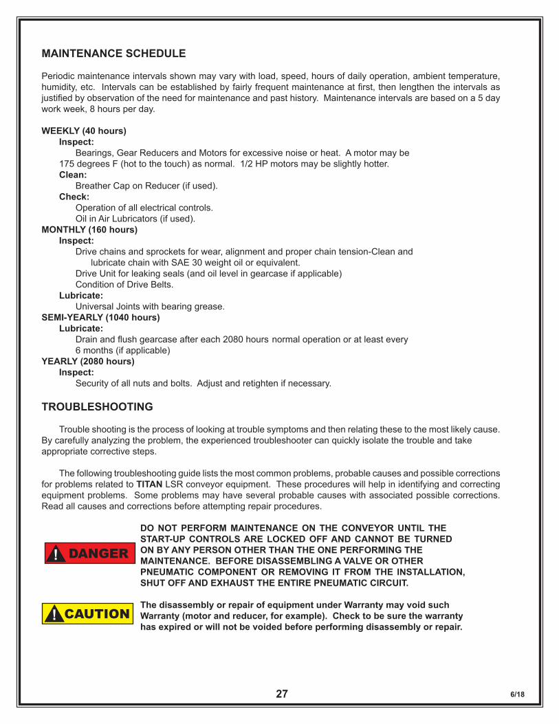
MAINTENANCE SCHEDULE
Periodic maintenance intervals shown may vary with load, speed, hours of daily operation, ambient temperature, humidity, etc. Intervals can be established by fairly frequent maintenance at first, then lengthen the intervals as justified by observation of the need for maintenance and past history. Maintenance intervals are based on a 5 day work week, 8 hours per day.
WEEKLY (40 hours) Inspect: Bearings, Gear Reducers and Motors for excessive noise or heat. A motor may be 175 degrees F (hot to the touch) as normal. 1/2 HP motors may be slightly hotter. Clean: Breather Cap on Reducer (if used). Check: Operation of all electrical controls. Oil in Air Lubricators (if used).MONTHLY (160 hours) Inspect: Drive chains and sprockets for wear, alignment and proper chain tension-Clean and lubricate chain with SAE 30 weight oil or equivalent. Drive Unit for leaking seals (and oil level in gearcase if applicable) Condition of Drive Belts. Lubricate: Universal Joints with bearing grease.SEMI-YEARLY (1040 hours) Lubricate: Drain and flush gearcase after each 2080 hours normal operation or at least every 6 months (if applicable)YEARLY (2080 hours) Inspect: Security of all nuts and bolts. Adjust and retighten if necessary.
TROUBLESHOOTING
Trouble shooting is the process of looking at trouble symptoms and then relating these to the most likely cause. By carefully analyzing the problem, the experienced troubleshooter can quickly isolate the trouble and take appropriate corrective steps.
The following troubleshooting guide lists the most common problems, probable causes and possible corrections for problems related to TITAN LSR conveyor equipment. These procedures will help in identifying and correcting equipment problems. Some problems may have several probable causes with associated possible corrections. Read all causes and corrections before attempting repair procedures.
DO NOT PERFORM MAINTENANCE ON THE CONVEYOR UNTIL THE START-UP CONTROLS ARE LOCKED OFF AND CANNOT BE TURNED ON BY ANY PERSON OTHER THAN THE ONE PERFORMING THE MAINTENANCE. BEFORE DISASSEMBLING A VALVE OR OTHER PNEUMATIC COMPONENT OR REMOVING IT FROM THE INSTALLATION, SHUT OFF AND EXHAUST THE ENTIRE PNEUMATIC CIRCUIT.
The disassembly or repair of equipment under Warranty may void such Warranty (motor and reducer, for example). Check to be sure the warranty has expired or will not be voided before performing disassembly or repair.
DANGER!
CAUTION!
6/1828
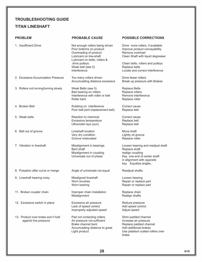
TROUBLESHOOTING GUIDE
TITAN LINESHAFT
PROBLEM PROBABLE CAUSE POSSIBLE CORRECTIONS
1. Insufficient Drive Not enough rollers being driven Drive more rollers, if available Poor bottoms on product Improve product conveyability Overloading of product Remove overload Lubricant on line-shaft Clean Shaft with liquid degreaser Lubricant on belts, rollers & drive pulleys Clean belts, rollers and pulleys Weak belt (see 5) Replace belts Interference Locate and correct interference
2. Excessive Accumulation Pressure Too many rollers driven Drive fewer rollers Accumulating distance excessive Break up pressure with Brakes
3. Rollers not turning/turning slowly Weak Belts (see 5) Replace Belts Bad bearing on rollers Replace rollers Interference with roller or belt Remove interference Roller bent Replace roller
4. Broken Belt Rubbing on interference Correct cause Poor belt joint (replacement belt) Replace belt
5. Weak belts Reaction to chemical Correct cause Excessive temperature Replace belt Ultraviolet rays (sun) Replace belt
6. Belt out of groove Lineshaft location Move shaft Very dry condition Lightly oil groove Groove mislocated Replace roller
7. Vibration in lineshaft Misalignment in bearings Loosen bearing and readjust shaft Bent shaft Replace shaft Misalignment in coupling realign coupling Universals out of phase Key one end of center shaft in alignment with opposite key. Equalize angles.
8. Pulsation after curve or merge Angle of universals not equal Readjust shafts.
9. Lineshaft bearing noisy Misaligned lineshaft Loosen bearing Worn brushes Repair or replace part Worn bearing Repair or replace part
11. Broken coupler chain Improper chain installation Replace chain Misalignment Realign shafts
12. Excessive switch in place Excessive air pressure Reduce pressure Lack of speed control Add speed control Improperly adjusted speed Adjust speed
13. Product over brake won’t hold Pad not contacting rollers Shim padded channel against line pressure Air pressure not sufficient Increase air pressure Brake channel bent Replace padded channel Accumulating distance to great Add additional brakes Light product Use plastisol coated rollers over brake
6/1829
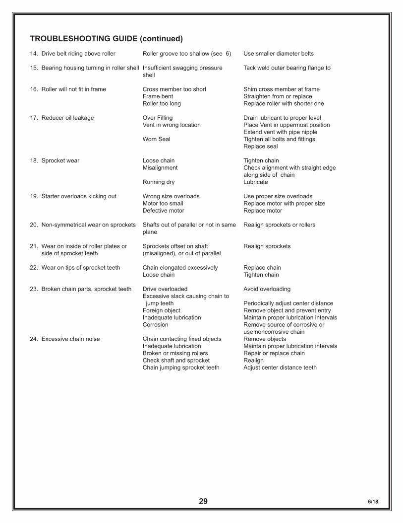
TROUBLESHOOTING GUIDE (continued)
14. Drive belt riding above roller Roller groove too shallow (see 6) Use smaller diameter belts
15. Bearing housing turning in roller shell Insufficient swagging pressure Tack weld outer bearing flange to shell
16. Roller will not fit in frame Cross member too short Shim cross member at frame Frame bent Straighten from or replace Roller too long Replace roller with shorter one
17. Reducer oil leakage Over Filling Drain lubricant to proper level Vent in wrong location Place Vent in uppermost position Extend vent with pipe nipple Worn Seal Tighten all bolts and fittings Replace seal
18. Sprocket wear Loose chain Tighten chain Misalignment Check alignment with straight edge along side of chain Running dry Lubricate
19. Starter overloads kicking out Wrong size overloads Use proper size overloads Motor too small Replace motor with proper size Defective motor Replace motor
20. Non-symmetrical wear on sprockets Shafts out of parallel or not in same Realign sprockets or rollers plane 21. Wear on inside of roller plates or Sprockets offset on shaft Realign sprockets side of sprocket teeth (misaligned), or out of parallel
22. Wear on tips of sprocket teeth Chain elongated excessively Replace chain Loose chain Tighten chain
23. Broken chain parts, sprocket teeth Drive overloaded Avoid overloading Excessive slack causing chain to jump teeth Periodically adjust center distance Foreign object Remove object and prevent entry Inadequate lubrication Maintain proper lubrication intervals Corrosion Remove source of corrosive or use noncorrosive chain24. Excessive chain noise Chain contacting fixed objects Remove objects Inadequate lubrication Maintain proper lubrication intervals Broken or missing rollers Repair or replace chain Check shaft and sprocket Realign Chain jumping sprocket teeth Adjust center distance teeth
6/1830
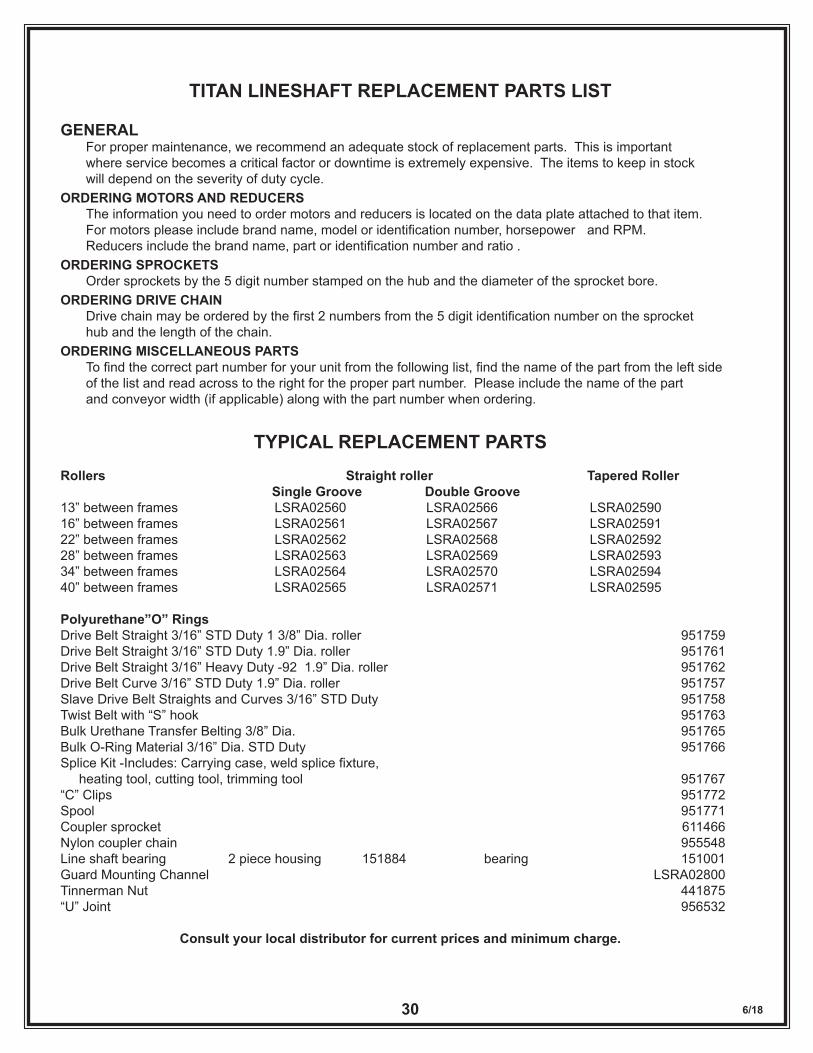
TITAN LINESHAFT REPLACEMENT PARTS LIST
GENERAL For proper maintenance, we recommend an adequate stock of replacement parts. This is important where service becomes a critical factor or downtime is extremely expensive. The items to keep in stock will depend on the severity of duty cycle.ORDERING MOTORS AND REDUCERS The information you need to order motors and reducers is located on the data plate attached to that item. For motors please include brand name, model or identification number, horsepower and RPM. Reducers include the brand name, part or identification number and ratio .ORDERING SPROCKETS Order sprockets by the 5 digit number stamped on the hub and the diameter of the sprocket bore.ORDERING DRIVE CHAIN Drive chain may be ordered by the first 2 numbers from the 5 digit identification number on the sprocket hub and the length of the chain.ORDERING MISCELLANEOUS PARTS To find the correct part number for your unit from the following list, find the name of the part from the left side of the list and read across to the right for the proper part number. Please include the name of the part and conveyor width (if applicable) along with the part number when ordering.
TYPICAL REPLACEMENT PARTSRollers Straight roller Tapered Roller Single Groove Double Groove13” between frames LSRA02560 LSRA02566 LSRA02590 16” between frames LSRA02561 LSRA02567 LSRA0259122” between frames LSRA02562 LSRA02568 LSRA0259228” between frames LSRA02563 LSRA02569 LSRA0259334” between frames LSRA02564 LSRA02570 LSRA0259440” between frames LSRA02565 LSRA02571 LSRA02595
Polyurethane”O” RingsDrive Belt Straight 3/16” STD Duty 1 3/8” Dia. roller 951759Drive Belt Straight 3/16” STD Duty 1.9” Dia. roller 951761Drive Belt Straight 3/16” Heavy Duty -92 1.9” Dia. roller 951762Drive Belt Curve 3/16” STD Duty 1.9” Dia. roller 951757Slave Drive Belt Straights and Curves 3/16” STD Duty 951758Twist Belt with “S” hook 951763Bulk Urethane Transfer Belting 3/8” Dia. 951765Bulk O-Ring Material 3/16” Dia. STD Duty 951766Splice Kit -Includes: Carrying case, weld splice fixture, heating tool, cutting tool, trimming tool 951767“C” Clips 951772Spool 951771Coupler sprocket 611466Nylon coupler chain 955548Line shaft bearing 2 piece housing 151884 bearing 151001Guard Mounting Channel LSRA02800Tinnerman Nut 441875“U” Joint 956532
Consult your local distributor for current prices and minimum charge.
6/1831
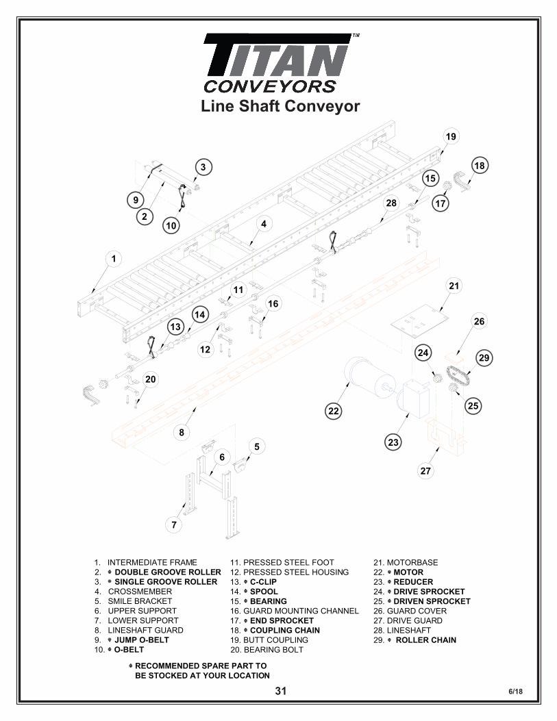
Line Shaft Conveyor
1
2
3
4
56
7
8
9
10
11
12
1314
15
16
17
18
19
20
21
22
23
24
25
26
27
28
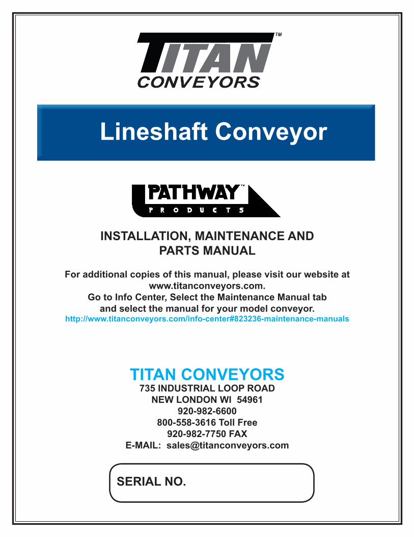
MODEL LSR INTERMEDIATE DRIVE CONVEYOR
1. INTERMEDIATE FRAME2. DOUBLE GROOVE ROLLER3. SINGLE GROOVE ROLLER4. CROSSMEMBER5. SMILE BRACKET6. UPPER SUPPORT7. LOWER SUPPORT8. LINESHAFT GUARD9. JUMP O-BELT10. O-BELT
11. PRESSED STEEL FOOT12. PRESSED STEEL HOUSING13. C-CLIP14. SPOOL15. BEARING16. GUARD MOUNTING CHANNEL17. END SPROCKET18. COUPLING CHAIN19. BUTT COUPLING20. BEARING BOLT
21. MOTORBASE22. MOTOR23. REDUCER24. DRIVE SPROCKET25. DRIVEN SPROCKET26. GUARD COVER27. DRIVE GUARD28. LINESHAFT29. ROLLER CHAIN
RECOMMENDED SPARE PART TOBE STOCKED AT YOUR LOCATION
29
6/1832
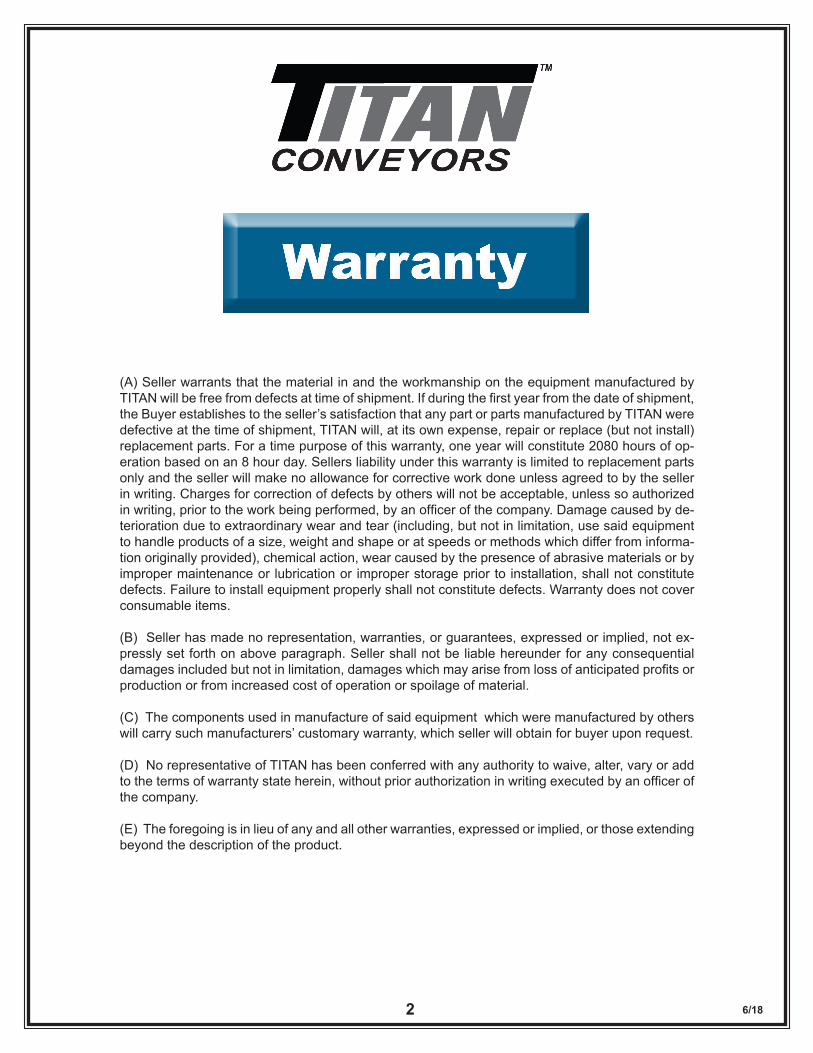
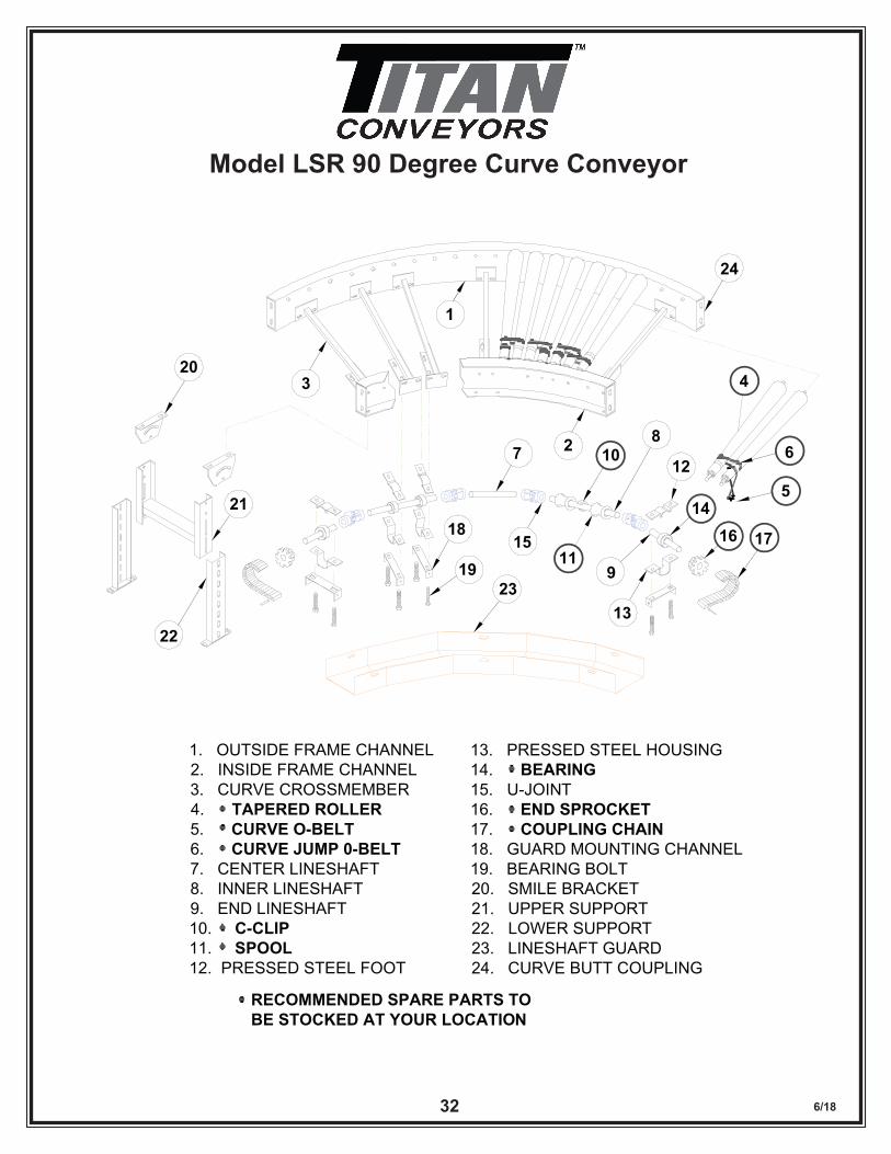
Model LSR 90 Degree Curve Conveyor
1
2
3 4
6
5
7 108
9
12
14
13
1115 16 1718
19
20
21
22
23
24
MODEL LSR 90° CURVECONVEYOR
1. OUTSIDE FRAME CHANNEL2. INSIDE FRAME CHANNEL3. CURVE CROSSMEMBER4. TAPERED ROLLER5. CURVE O-BELT6. CURVE JUMP 0-BELT7. CENTER LINESHAFT8. INNER LINESHAFT9. END LINESHAFT10. C-CLIP11. SPOOL12. PRESSED STEEL FOOT
13. PRESSED STEEL HOUSING14. BEARING15. U-JOINT16. END SPROCKET17. COUPLING CHAIN18. GUARD MOUNTING CHANNEL19. BEARING BOLT20. SMILE BRACKET21. UPPER SUPPORT22. LOWER SUPPORT23. LINESHAFT GUARD24. CURVE BUTT COUPLING
RECOMMENDED SPARE PARTS TOBE STOCKED AT YOUR LOCATION
NEW
6/1833
1
2
3456789101112131415
16
17
17
18
19
20
21 22
25
23
24
26
27
18
28
29
3031
2
33
32
34
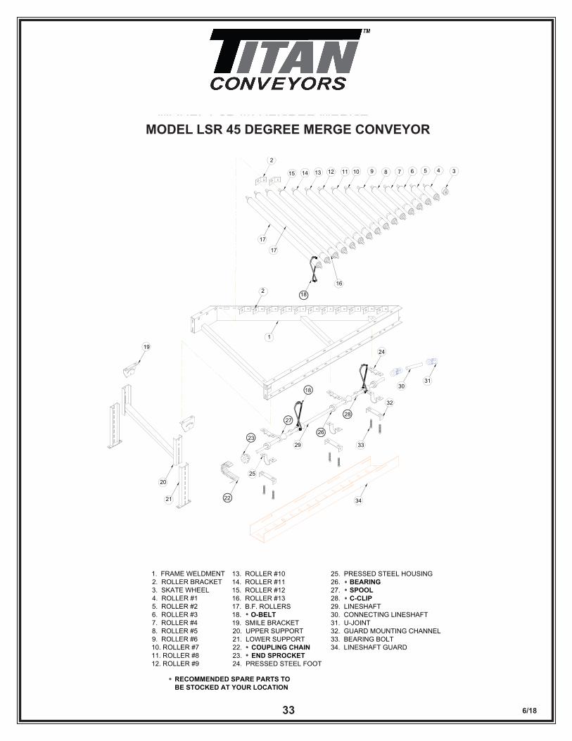
MODEL LSR 45 DEGREE MERGECONVEYOR
1. FRAME WELDMENT2. ROLLER BRACKET3. SKATE WHEEL4. ROLLER #15. ROLLER #26. ROLLER #37. ROLLER #48. ROLLER #59. ROLLER #610. ROLLER #711. ROLLER #812. ROLLER #9
13. ROLLER #1014. ROLLER #1115. ROLLER #1216. ROLLER #1317. B.F. ROLLERS18. O-BELT19. SMILE BRACKET20. UPPER SUPPORT21. LOWER SUPPORT22. COUPLING CHAIN23. END SPROCKET24. PRESSED STEEL FOOT
25. PRESSED STEEL HOUSING26. BEARING27. SPOOL28. C-CLIP29. LINESHAFT30. CONNECTING LINESHAFT31. U-JOINT32. GUARD MOUNTING CHANNEL33. BEARING BOLT34. LINESHAFT GUARD
RECOMMENDED SPARE PARTS TOBE STOCKED AT YOUR LOCATION
MODEL LSR 45 DEGREE MERGE CONVEYOR
33
6/1834
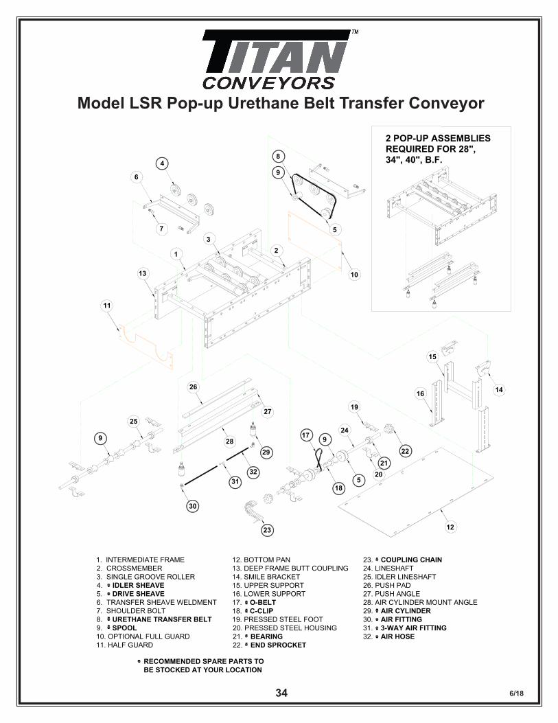
Model LSR Pop-up Urethane Belt Transfer ConveyorMODEL LSR POP-UP URETHANE BELT TRANSFER CONVEYOR
4
6
7
8
9
5
10
11
13
1
32
14
15
16
12
17
185
9
19
2120
22
23
24
27
2829
30
3132
26
25
9
2 POP-UP ASSEMBLIESREQUIRED FOR 28",34", 40", B.F.
1. INTERMEDIATE FRAME2. CROSSMEMBER3. SINGLE GROOVE ROLLER4. IDLER SHEAVE5. DRIVE SHEAVE6. TRANSFER SHEAVE WELDMENT7. SHOULDER BOLT8. URETHANE TRANSFER BELT9. SPOOL10. OPTIONAL FULL GUARD11. HALF GUARD
12. BOTTOM PAN13. DEEP FRAME BUTT COUPLING14. SMILE BRACKET15. UPPER SUPPORT16. LOWER SUPPORT17. O-BELT18. C-CLIP19. PRESSED STEEL FOOT20. PRESSED STEEL HOUSING21. BEARING22. END SPROCKET
23. COUPLING CHAIN24. LINESHAFT25. IDLER LINESHAFT26. PUSH PAD27. PUSH ANGLE28. AIR CYLINDER MOUNT ANGLE29. AIR CYLINDER30. AIR FITTING31. 3-WAY AIR FITTING32. AIR HOSE
RECOMMENDED SPARE PARTS TOBE STOCKED AT YOUR LOCATION

6/1835
TITAN CONVEYORS735 INDUSTRIAL LOOP ROAD
NEW LONDON WI 54961920-982-6600
800-558-3616 Toll Free920-982-7750 FAX
E-MAIL: [email protected]: www.titanconveyors.com
Contact Your Distributor or Titan Directly for Further Information on Other Titan Conveyor Products n Slider Bed Conveyors n Floor to Floor Belt Conveyors n Parts Conveyors n Gravity Roller Conveyors n Line Shaft Conveyors n Chain Driven Live Roller Conveyors n Belt Driven Live Roller Conveyors n Zone Accumulation & Special Applications n Hinged Steel Belt Conveyors n Slat Conveyors n Wire Mesh Conveyors n Multi-Strand Conveyors n Motorized Roller Conveyors n Solid Waste Belt Conveyors n Bulk Handling Conveyors n Special Projects