Embed Size (px)
Citation preview
LineShAFT DRiven ROLLeR COnveyOR
Section content
StraightCurveStraight SpurOptional Equipment and Devices
75
P.O. Box 352 n Alpena, Michigan 49707Phone 989.358.7000Fax [email protected]
77
LS
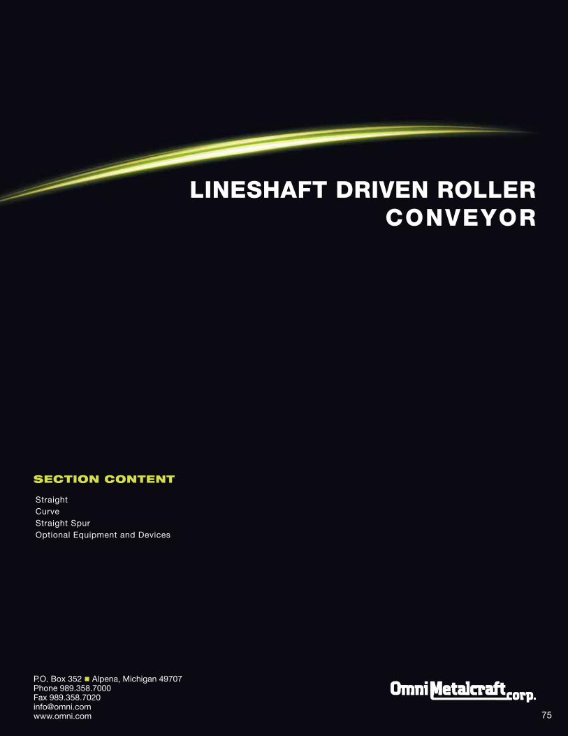
1.4" 1.9"A 10" - 28" 13" - 39"B 3' - 70' 3' - 110'C 11" - 88"D A + 3"
A = Between Frame (BF) (1" Increments) B = Overall Length (OAL) (Any Increment)C = Top of Roller (TOR)D = Overall Width (OAW)
LineShaFt DRiVen RoLLeR conVeYoR
LineShaFt conVeYoR - StRaight
Flow
DRive Belt
DRive sPool
RolleR
DRive sHaFt
RetaininG cliP
Why LS?
n Maximum conveyor length per AC drive available n Economical conveyance of loads up to 75 lbs. or 15 lbs. per roller n Easily add slaved components; curves, spurs and transfers n Increased driving force with optional keyed spools and high tension bands n Full line of standard modular accessories n Common applications include box, tote or tray transportation and minimum pressure accumulation
B
21 1/4"DRive sPools c
DRive Belt
sPool GuaRD
26 3/4"
14 1/4"
1 1/2"
5 1/2"
2"
2 3/4"
4 7/8"
sPoolGuaRD
DRive Belt
1.9 ROLLeR
1/4"
5 1/8"
1.4 ROLLeR
3/16"
a
D
10 3/4"
20" to 25"
15 1/2"
21 1/4"
UnDeRhUnG DRive SiDe MOUnTeD DRive
19" to 23 1/2"
a
D
1 1/2"
5 1/2"
2"
sPoolGuaRD
2 3/4"
DRive Belt
Underhung drive shown
78
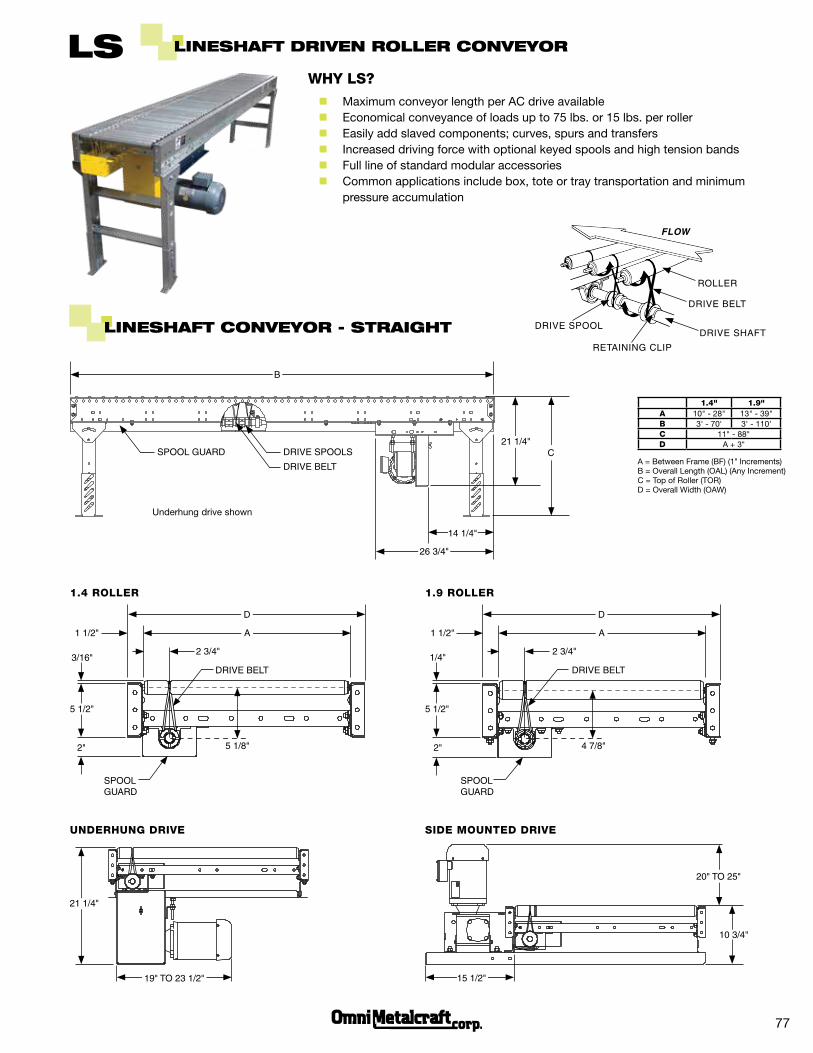
Note: 30° curves are supplied with 12" minimum tangents
60° CURve
45°
12"
12"
30°
45° CURve30° CURve
LineShaFt conVeYoR - cuRVe
1.4" 1.9"A 10" - 28" 13" - 39"B 46" - 64" 49" - 75"C 11" - 88"D 36"e 30°, 45°, 60° and 90°
A = Between Frame (BF) (1" Increments) B = Outside Radius (OR)C = Top of Roller (TOR)D = Inside Radius (IR)E = Degree a D
B
e
a
c
1.9 TAPeReD ROLLeR
1 1/2"
sPoolGuaRD
DRive sPoolDRive Belt
1/4"
2"
5 1/2"
1.4 TAPeReD ROLLeR
Between FRaMe wiDtH1 1/2"
2"
2 3/4"
DRive sPoolDRive Belt
3/16"
sPoolGuaRD
5 1/2"
90° CURve
Between FRaMe wiDtH
2 3/4"
Taper and straight rollers available for curves
D DD
60°
79
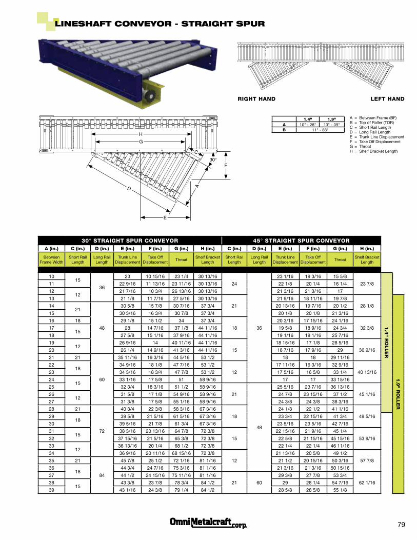
1.4" 1.9" A 10" - 28" 13" - 39"B 11" - 88"
A = Between Frame (BF)B = Top of Roller (TOR) C = Short Rail LengthD = Long Rail LengthE = Trunk Line DisplacementF = Take Off DisplacementG = ThroatH = Shelf Bracket Length
LineShaFt conVeYoR - StRaight SPuR
30° STRAiGhT SPUR COnveyOR 45° STRAiGhT SPUR COnveyORA (in.) C (in.) D (in.) e (in.) F (in.) G (in.) h (in.) C (in.) D (in.) e (in.) F (in.) G (in.) h (in.)
Between Frame Width
Short Rail Length
Long Rail Length
Trunk Line Displacement
Take Off Displacement
ThroatShelf Bracket
LengthShort Rail
LengthLong Rail Length
Trunk Line Displacement
Take Off Displacement
ThroatShelf Bracket
Length
1015
36
23 10 15/16 23 1/4 30 13/16
24
36
23 1/16 19 3/16 15 5/8
23 7/8
1.4
" RO
LLe
R
11 22 9/16 11 13/16 23 11/16 30 13/16 22 1/8 20 1/4 16 1/4
1212
21 7/16 10 3/4 26 13/16 30 13/16 21 3/16 21 3/16 17
13 21 1/8 11 7/16 27 5/16 30 13/16
21
21 9/16 18 11/16 19 7/8
28 1/8
1.9
" RO
LLe
R
1421
48
30 5/8 15 7/8 30 7/16 37 3/4 20 13/16 19 7/16 20 1/2
15 30 3/16 16 3/4 30 7/8 37 3/4 20 1/8 20 1/8 21 3/16
16 18 29 1/8 15 1/2 34 37 3/4
18
20 3/16 17 15/16 24 1/16
32 3/81715
28 14 7/16 37 1/8 44 11/16 19 5/8 18 9/16 24 3/4
18 27 5/8 15 1/16 37 9/16 44 11/16 19 1/16 19 1/16 25 7/16
1912
26 9/16 14 40 11/16 44 11/16
15
18 15/16 17 1/8 28 5/16
36 9/1620 26 1/4 14 9/16 41 3/16 44 11/16 18 7/16 17 9/16 29
21 21
60
35 11/16 19 3/16 44 5/16 53 1/2 18 18 29 11/16
2218
34 9/16 18 1/8 47 7/16 53 1/2
12
17 11/16 16 3/16 32 9/16
40 13/1623 34 3/16 18 3/4 47 7/8 53 1/2 17 5/16 16 5/8 33 1/4
2415
33 1/16 17 5/8 51 58 9/16 17 17 33 15/16
25 32 3/4 18 3/16 51 1/2 58 9/16
21
48
25 5/16 23 7/16 36 13/16
45 1/162612
31 5/8 17 1/8 54 9/16 58 9/16 24 7/8 23 15/16 37 1/2
27 31 3/8 17 5/8 55 1/16 58 9/16 24 3/8 24 3/8 38 3/16
28 21
72
40 3/4 22 3/8 58 3/16 67 3/16
18
24 1/8 22 1/2 41 1/16
49 5/162918
39 5/8 21 5/16 61 5/16 67 3/16 23 3/4 22 15/16 41 3/4 30 39 5/16 21 7/8 61 3/4 67 3/16 23 5/16 23 5/16 42 7/16
3115
38 3/16 20 13/16 64 7/8 72 3/8
15
22 15/16 21 9/16 45 1/4
53 9/1632 37 15/16 21 5/16 65 3/8 72 3/8 22 5/8 21 15/16 45 15/16
3312
36 13/16 20 1/4 68 1/2 72 3/8 22 1/4 22 1/4 46 11/16
34 36 9/16 20 11/16 68 15/16 72 3/8
12
21 13/16 20 5/8 49 1/2
57 7/835 21
84
45 7/8 25 1/2 72 1/16 81 1/16 21 1/2 20 15/16 50 3/16
3618
44 3/4 24 7/16 75 3/16 81 1/16 21 3/16 21 3/16 50 15/16
37 44 1/2 24 15/16 75 11/16 81 1/16
21 60
29 3/8 27 7/8 53 3/4
62 1/163815
43 3/8 23 7/8 78 3/4 84 1/2 29 28 1/4 54 7/16
39 43 1/16 24 3/8 79 1/4 84 1/2 28 5/8 28 5/8 55 1/8
RiGhT hAnD LeFT hAnD
a
F
H
G
D
e
c
30°
80
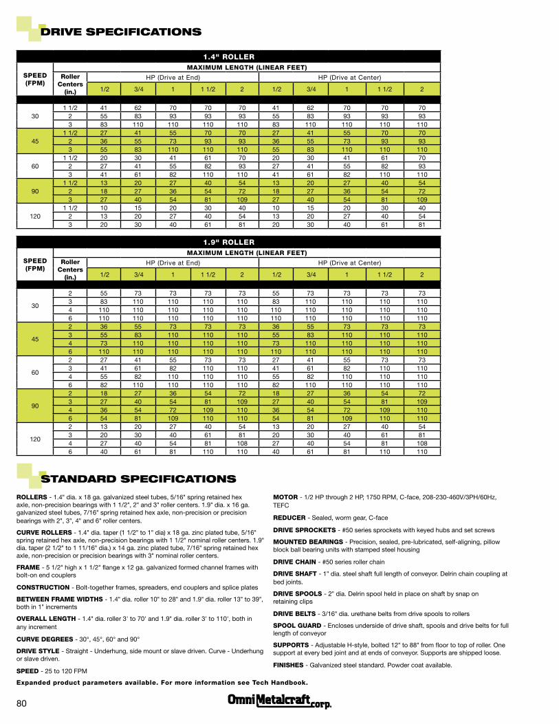
DRiVe SPeciFicationS
1.4" ROLLeR
SPeeD (FPM)
MAXiMUM LenGTh (LineAR FeeT)Roller
Centers (in.)
HP (Drive at End) HP (Drive at Center)
1/2 3/4 1 1 1/2 2 1/2 3/4 1 1 1/2 2
301 1/2 41 62 70 70 70 41 62 70 70 70
2 55 83 93 93 93 55 83 93 93 933 83 110 110 110 110 83 110 110 110 110
451 1/2 27 41 55 70 70 27 41 55 70 70
2 36 55 73 93 93 36 55 73 93 933 55 83 110 110 110 55 83 110 110 110
601 1/2 20 30 41 61 70 20 30 41 61 70
2 27 41 55 82 93 27 41 55 82 933 41 61 82 110 110 41 61 82 110 110
901 1/2 13 20 27 40 54 13 20 27 40 54
2 18 27 36 54 72 18 27 36 54 723 27 40 54 81 109 27 40 54 81 109
1201 1/2 10 15 20 30 40 10 15 20 30 40
2 13 20 27 40 54 13 20 27 40 543 20 30 40 61 81 20 30 40 61 81
1.9" ROLLeR
SPeeD (FPM)
MAXiMUM LenGTh (LineAR FeeT)Roller
Centers (in.)
HP (Drive at End) HP (Drive at Center)
1/2 3/4 1 1 1/2 2 1/2 3/4 1 1 1/2 2
30
2 55 73 73 73 73 55 73 73 73 733 83 110 110 110 110 83 110 110 110 1104 110 110 110 110 110 110 110 110 110 1106 110 110 110 110 110 110 110 110 110 110
45
2 36 55 73 73 73 36 55 73 73 733 55 83 110 110 110 55 83 110 110 1104 73 110 110 110 110 73 110 110 110 1106 110 110 110 110 110 110 110 110 110 110
60
2 27 41 55 73 73 27 41 55 73 733 41 61 82 110 110 41 61 82 110 1104 55 82 110 110 110 55 82 110 110 1106 82 110 110 110 110 82 110 110 110 110
90
2 18 27 36 54 72 18 27 36 54 723 27 40 54 81 109 27 40 54 81 1094 36 54 72 109 110 36 54 72 109 1106 54 81 109 110 110 54 81 109 110 110
120
2 13 20 27 40 54 13 20 27 40 543 20 30 40 61 81 20 30 40 61 814 27 40 54 81 108 27 40 54 81 1086 40 61 81 110 110 40 61 81 110 110
ROLLeRS - 1.4" dia. x 18 ga. galvanized steel tubes, 5/16" spring retained hex axle, non-precision bearings with 1 1/2", 2" and 3" roller centers. 1.9" dia. x 16 ga. galvanized steel tubes, 7/16" spring retained hex axle, non-precision or precision bearings with 2", 3", 4" and 6" roller centers.
CURve ROLLeRS - 1.4" dia. taper (1 1/2" to 1" dia) x 18 ga. zinc plated tube, 5/16" spring retained hex axle, non-precision bearings with 1 1/2" nominal roller centers. 1.9" dia. taper (2 1/2" to 1 11/16" dia.) x 14 ga. zinc plated tube, 7/16" spring retained hex axle, non-precision or precision bearings with 3" nominal roller centers.
FRAMe - 5 1/2" high x 1 1/2" flange x 12 ga. galvanized formed channel frames with bolt-on end couplers
COnSTRUCTiOn - Bolt-together frames, spreaders, end couplers and splice plates
BeTWeen FRAMe WiDThS - 1.4" dia. roller 10" to 28" and 1.9" dia. roller 13" to 39", both in 1" increments
OveRALL LenGTh - 1.4" dia. roller 3' to 70' and 1.9" dia. roller 3' to 110', both in any increment
CURve DeGReeS - 30°, 45°, 60° and 90°
DRive STyLe - Straight - Underhung, side mount or slave driven. Curve - Underhung or slave driven.
SPeeD - 25 to 120 FPM
MOTOR - 1/2 HP through 2 HP, 1750 RPM, C-face, 208-230-460V/3PH/60Hz, TEFC
ReDUCeR - Sealed, worm gear, C-face
DRive SPROCKeTS - #50 series sprockets with keyed hubs and set screws
MOUnTeD BeARinGS - Precision, sealed, pre-lubricated, self-aligning, pillow block ball bearing units with stamped steel housing
DRive ChAin - #50 series roller chain
DRive ShAFT - 1" dia. steel shaft full length of conveyor. Delrin chain coupling at bed joints.
DRive SPOOLS - 2" dia. Delrin spool held in place on shaft by snap on retaining clips
DRive BeLTS - 3/16" dia. urethane belts from drive spools to rollers
SPOOL GUARD - Encloses underside of drive shaft, spools and drive belts for full length of conveyor
SUPPORTS - Adjustable H-style, bolted 12" to 88" from floor to top of roller. One support at every bed joint and at ends of conveyor. Supports are shipped loose.
FiniSheS - Galvanized steel standard. Powder coat available.
StanDaRD SPeciFicationS
expanded product parameters available. For more information see Tech handbook.
ST
RA
iGh
TROLLeR
DiAMeTeR
BeARinGS TUBe DeTAiL AXLe DeTAiLROLLeR SPACinG
MAXiMUM LOAD PeR ROLLeR
GALvAniZeD FRAMeMAXiMUM LOAD PeR PRODUCT
DetailsWall
ThicknessMaterial Size Type Retention Centers lbs. 12 Ga. Formed Channels lbs.
1.4" Non-Precision 18 Ga. Galvanized 5/16" Hex Spring 1 1/2", 2" and 3" 10 5 1/2" high x 1 1/2" flange 75
1.9"Non-Precision or ABEC Precision
16 Ga. Galvanized 7/16" Hex Spring 2", 3", 4" and 6" 15 5 1/2" high x 1 1/2" flange 75
CU
Rv
e
CURve TyPeinSiDe RADiUS
ROLLeR DiAMeTeR
BeARinGS TUBe DeTAiL AXLe DeTAiLROLLeR SPACinG
MAXiMUM LOAD PeR ROLLeR
MAXiMUM LOAD PeR PRODUCT
DetailsWall
ThicknessMaterial Size Type Retention Centers lbs. lbs.
30°, 45°, 60°, 90°
36"1.4" Tapered (1 1/2" - 1")
Non-Precision 18 Ga. Zinc Plated 5/16" Hex Spring1 1/2"
Nominal 10 75
36"1.9" Tapered
(2 1/2" - 1 11/16")Non-Precision or ABEC Precision
14 Ga. Zinc Plated 7/16" Hex Spring3"
Nominal15 75
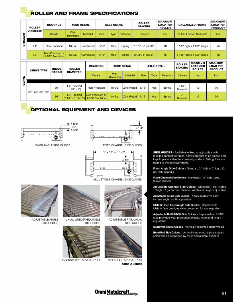
RoLLeR anD FRaMe SPeciFicationS
oPtionaL equiPMent anD DeViceS
FIXED ANGLE SIDE GUIDES
1 3/4"oR
5 3/4"
FIXED CHANNEL SIDE GUIDES
3 1/4"
ADjUSTABLE CHANNEL SIDE GUIDES
5 1/4"
BF + 10" to BF - 2" SidE GuidES - Available in fixed or adjustable with multiple contact surfaces. Allows product to be guided and kept in place within the conveying surface. Side guides are bolted to the conveyor frame.
Fixed Angle Side Guides - Standard 2" high or 6" high, 12 ga. formed angle
Fixed Channel Side Guides - Standard 3 1/2" high, 12 ga. formed channel
Adjustable Channel Side Guides - Standard 1 5/8" high x 1" high, 12 ga. formed channel, width and height adjustable
Adjustable Angle Side Guides - Angle guides typically formed angle, width adjustable
UHMW Lined Fixed Angle Side Guides - Replaceable UHMW face provides wear protection for angle guides
Adjustable Rail UHMW Side Guides - Replaceable UHMW face provides wear protection on rails, width and height adjustable
Skatewheel Side Guides - Vertically mounted skatewheels
Bead Rail Side Guides - Vertically mounted, tightly spaced small wheels supported by axles and a metal channel
SKATEWHEEL SIDE GUIDES BEAD RAIL SIDE GUIDES
ADjUSTABLE ANGLE SIDE GUIDES
ADjUSTABLE RAIL UHMW SIDE GUIDES
UHMW LINED FIXED ANGLE SIDE GUIDES
81
SidE GuidES
FIXED ANGLE STOPS
1 11/16"
FIXED CHANNEL STOPS
1 3/4"
FIXED ROLLER STOPS
1 13/16"
ADjUSTABLE END STOPS
SIDE VIEW
5/8 - 11 threaded rod x 10'
END VIEW
BF + 12 1/2"
MULTI-TIER SUPPORTS PORTABLE H-STANDS
KNEE BRACE SUPPORTS
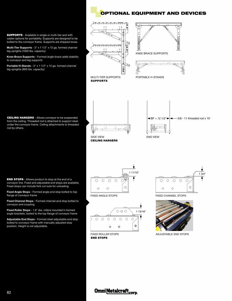
oPtionaL equiPMent anD DeViceS
SuppOrTS - Available in single or multi-tier and with caster options for portability. Supports are designed to be bolted to the conveyor frame. Supports are shipped loose.
Multi-Tier Supports - 3" x 1 1/2" x 12 ga. formed channel leg uprights (1500 lbs. capacity)
Knee Brace Supports - Formed angle brace adds stability to conveyor and leg supports
Portable H-Stands - 3" x 1 1/2" x 12 ga. formed channel leg uprights (800 lbs. capacity)
CEiLiNG HANGErS - Allows conveyor to be suspended from the ceiling. Threaded rod is attached to support steel under the conveyor frame. Ceiling attachments to threaded rod by others.
ENd STOpS - Allows product to stop at the end of a conveyor line. Fixed and adjustable end stops are available. Fixed stops can include fork cut outs for unloading.
Fixed Angle Stops - Formed angle end stop bolted to top flange of conveyor frame
Fixed Channel Stops - Formed channel end stop bolted to conveyor end coupling
Fixed Roller Stops - 1.9" dia. rollers mounted in formed angle brackets, bolted to the top flange of conveyor frame
Adjustable End Stops - Formed steel adjustable end stop bolted to conveyor frame with manually adjusted stop position. Height is not adjustable.
82
CEiLiNG HANGErS
SuppOrTS
ENd STOpS
Between FRaMe
5 3/4"
7"
1 3/4"
12 3/4" Min toR
aiR cylinDeR 13 1/2"
SIDE VIEWEND VIEWPNEUMATIC POP-UP BLADE STOPS
MANUAL POP-UP BLADE STOPS
5 3/4"
7"
1 3/4"
12 3/4" Min toR
13 1/2"
SIDE VIEW
Between FRaMe
END VIEW
oPtionaL equiPMent anD DeViceS
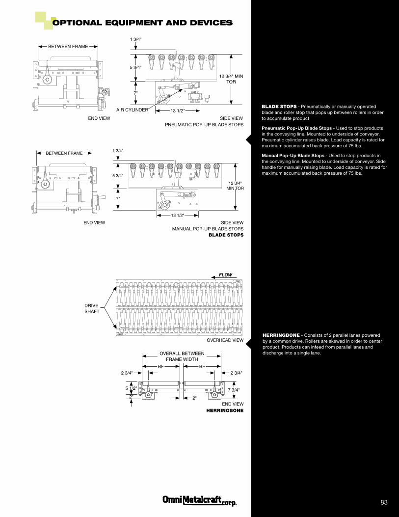
BLAdE STOpS - Pneumatically or manually operated blade and roller stop that pops up between rollers in order to accumulate product
Pneumatic Pop-Up Blade Stops - Used to stop products in the conveying line. Mounted to underside of conveyor. Pneumatic cylinder raises blade. Load capacity is rated for maximum accumulated back pressure of 75 lbs.
Manual Pop-Up Blade Stops - Used to stop products in the conveying line. Mounted to underside of conveyor. Side handle for manually raising blade. Load capacity is rated for maximum accumulated back pressure of 75 lbs.
Flow
DRive sHaFt
2 3/4" 2 3/4"
oveRall Between FRaMe wiDtH
BF BF
5 1/2"
2" 7 3/4"
2"
HErriNGBONE - Consists of 2 parallel lanes powered by a common drive. Rollers are skewed in order to center product. Products can infeed from parallel lanes and discharge into a single lane.
83
BLAdE STOpS
HErriNGBONE
OVERHEAD VIEW
END VIEW
oPtionaL equiPMent anD DeViceS
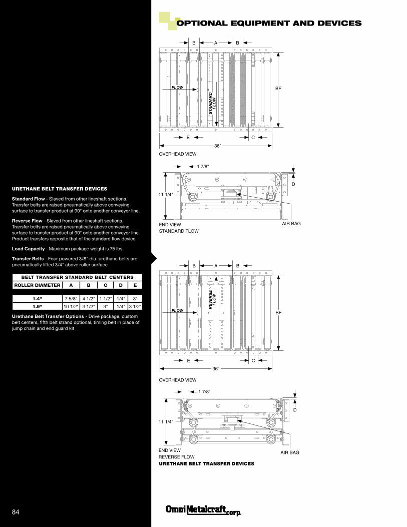
urETHANE BELT TrANSFEr dEviCES
Standard Flow - Slaved from other lineshaft sections. Transfer belts are raised pneumatically above conveying surface to transfer product at 90° onto another conveyor line.
Reverse Flow - Slaved from other lineshaft sections. Transfer belts are raised pneumatically above conveying surface to transfer product at 90° onto another conveyor line. Product transfers opposite that of the standard flow device.
Load Capacity - Maximum package weight is 75 lbs.
Transfer Belts - Four powered 3/8" dia. urethane belts are pneumatically lifted 3/4" above roller surface
BeLT TRAnSFeR STAnDARD BeLT CenTeRS
ROLLeR DiAMeTeR A B C D e
1.4" 7 5/8" 4 1/2" 1 1/2" 1/4" 3"
1.9" 10 1/2" 3 1/2" 3" 1/4" 3 1/2"
Urethane Belt Transfer Options - Drive package, custom belt centers, fifth belt strand optional, timing belt in place of jump chain and end guard kit
a
36"
B B
c
BF
e
1 7/8"
D
aiR BaG
11 1/4"
REVERSE FLOW
11 1/4"
1 7/8"
D
a
36"
B B
c
BF
e
STANDARD FLOW
84
aiR BaG
Flow
OVERHEAD VIEW
END VIEW
OVERHEAD VIEW
END VIEW
urETHANE BELT TrANSFEr dEviCES
Re
ve
Rs
e
Fl
ow
Flow
sta
nd
aR
d
Fl
ow
oPtionaL equiPMent anD DeViceS
85
BF
oveRall Between FRaMe wiDtH
Between lanesBF
a
B
B
standaRd Flow
ReveRse Flow
36"
c
e
Fl
ow
11"
1 7/8"
D
aiR BaG 23 1/4" Min toR
Flow
Fl
ow
a
36"
B B
c
BF
e
BI-DIRECTIONAL
5" Min 15" Max1 7/8" 1 7/8"
aiR BaG
BF
12 3/4" Min toR
Between lanesBF
DUAL LANE
Fl
ow
OVERHEAD VIEW
END VIEW
OVERHEAD VIEW
END VIEW
5" Min 15" Max
urETHANE BELT TrANSFEr dEviCES
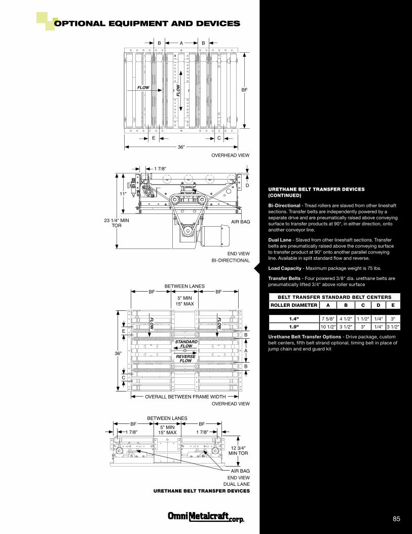
urETHANE BELT TrANSFEr dEviCES (COnTinUeD)
Bi-Directional - Tread rollers are slaved from other lineshaft sections. Transfer belts are independently powered by a separate drive and are pneumatically raised above conveying surface to transfer products at 90°, in either direction, onto another conveyor line.
Dual Lane - Slaved from other lineshaft sections. Transfer belts are pneumatically raised above the conveying surface to transfer product at 90° onto another parallel conveying line. Available in split standard flow and reverse.
Load Capacity - Maximum package weight is 75 lbs.
Transfer Belts - Four powered 3/8" dia. urethane belts are pneumatically lifted 3/4" above roller surface
BeLT TRAnSFeR STAnDARD BeLT CenTeRS
ROLLeR DiAMeTeR A B C D e
1.4" 7 5/8" 4 1/2" 1 1/2" 1/4" 3"
1.9" 10 1/2" 3 1/2" 3" 1/4" 3 1/2"
Urethane Belt Transfer Options - Drive package, custom belt centers, fifth belt strand optional, timing belt in place of jump chain and end guard kit
oPtionaL equiPMent anD DeViceS
86
72"
12" 18" Min toR
5 1/2"
cleaRance 38" (aPPRoxiMate)
BRake Zone 1 1/2', 2', 2 1/2', 3', 3 1/2'
48"
SIDE VIEW
8"
2" 1/4"
aiR Puck
2 3/4"
END VIEW
SkEwEd rOLLErSrOLLEr COATiNGS Or SLEEvES
pNEuMATiC rOLLEr BrAkE
SpriNG ASSiSTEd LiFT GATE SECTiON UP
DOWN
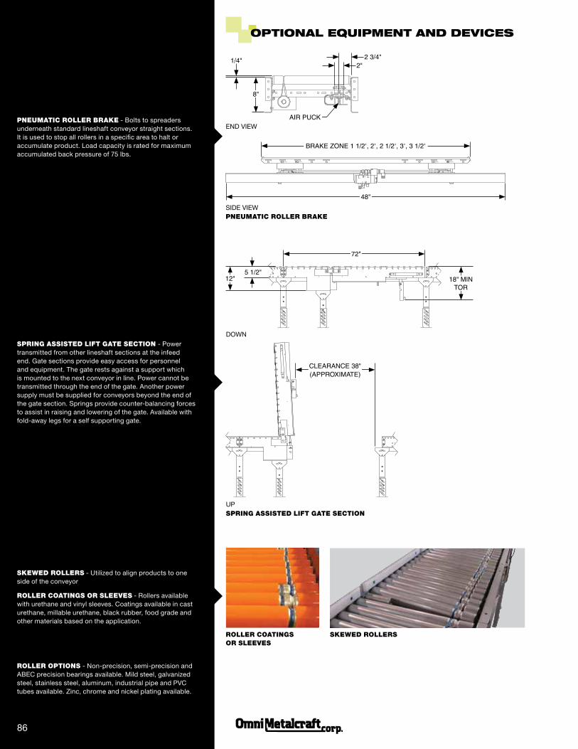
pNEuMATiC rOLLEr BrAkE - Bolts to spreaders underneath standard lineshaft conveyor straight sections. It is used to stop all rollers in a specific area to halt or accumulate product. Load capacity is rated for maximum accumulated back pressure of 75 lbs.
SpriNG ASSiSTEd LiFT GATE SECTiON - Power transmitted from other lineshaft sections at the infeed end. Gate sections provide easy access for personnel and equipment. The gate rests against a support which is mounted to the next conveyor in line. Power cannot be transmitted through the end of the gate. Another power supply must be supplied for conveyors beyond the end of the gate section. Springs provide counter-balancing forces to assist in raising and lowering of the gate. Available with fold-away legs for a self supporting gate.
SkEwEd rOLLErS - Utilized to align products to one side of the conveyor
rOLLEr COATiNGS Or SLEEvES - Rollers available with urethane and vinyl sleeves. Coatings available in cast urethane, millable urethane, black rubber, food grade and other materials based on the application.
rOLLEr OpTiONS - Non-precision, semi-precision and ABEC precision bearings available. Mild steel, galvanized steel, stainless steel, aluminum, industrial pipe and PVC tubes available. Zinc, chrome and nickel plating available.