Embed Size (px)
Citation preview
1/26/10
1
Link State Routing
Observation: loop can be prevented if each node knows the actual network topology
In link-state routing, each node: • floods the network with the state (up, down) of its links • uses Dijkstra’s Shortest Path First (SPF) algorithm to compute a
shortest-path tree
What is advertised: • DV: all nodes reachable from me, advertised to all neighbors • LS: all my immediate neighbors, advertised to all nodes
1
Dijkstra’s Shortest Path First (SPF) Algorithm
A greedy algorithm for solving single-source shortest path problem • assume non-negative edge weights • even if we’re only interested in the path from s to a single destination, d, we need to find the shortest path from s to all vertices in G (otherwise, we might have missed a shorter path)
• if the shortest path from s to d passes through an intermediate node u, i.e., P = {s, . . . , u, . . . , d}, then P’ = {s, . . . , u} must be the shortest path from s to u
2
1/26/10
2
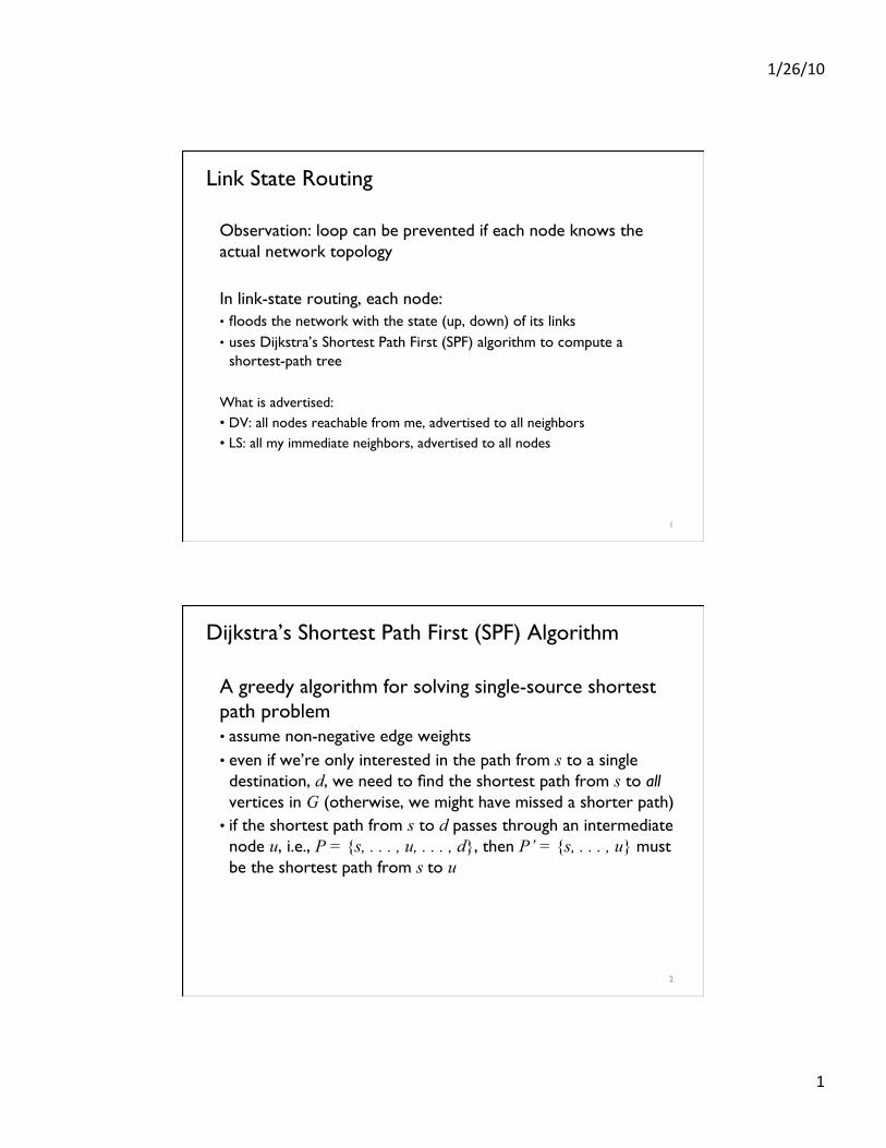
Dijkstra’s Shortest Path First (SPF) Algorithm
SPF(startnode s)!
{ // Initialize!
!table = createtable(|V|); // stores spf, cost, predecessor!!table[*].spf = false; table[*].cost = INFINITY;!
!pq = createpq(|E|); // empty pq!
!table[s].cost = 0;!
!pq.insert(0, s); // pq.insert(cost, v)!
!while (!pq.isempty()) {!! !v = pq.getMin();!
! !if (!table[v].spf) { // not on sp tree!
! ! !table[v].spf = true;!
! ! !for each u = v.neighbors() {!
! ! ! !newcost = weight(u, v) + table[v].cost; !! ! ! !if (table[u].cost > newcost) {!
! ! ! ! !table[u].cost = newcost;!
! ! ! ! !table[u].pred = v;!! ! ! ! !pq.insert(newcost, u);!! ! ! !}!! ! !}!! !}!!}!!extract SPF from table;!
}! 3
Dijkstra’s SPF Example (init)
u spf cost pred
a F ∞
b F 0 -
c F ∞
d F ∞
e F ∞
f F ∞
a
b c d
e f
3
5
1 5
1
5 4
2
4
1/26/10
3
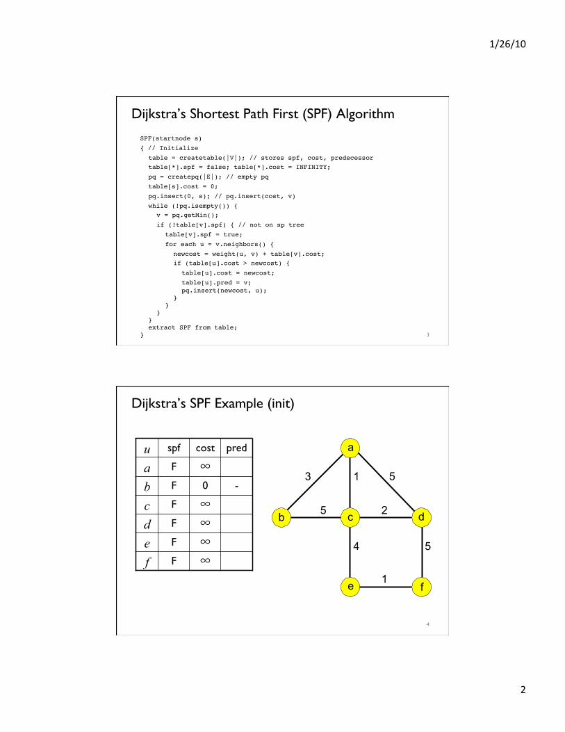
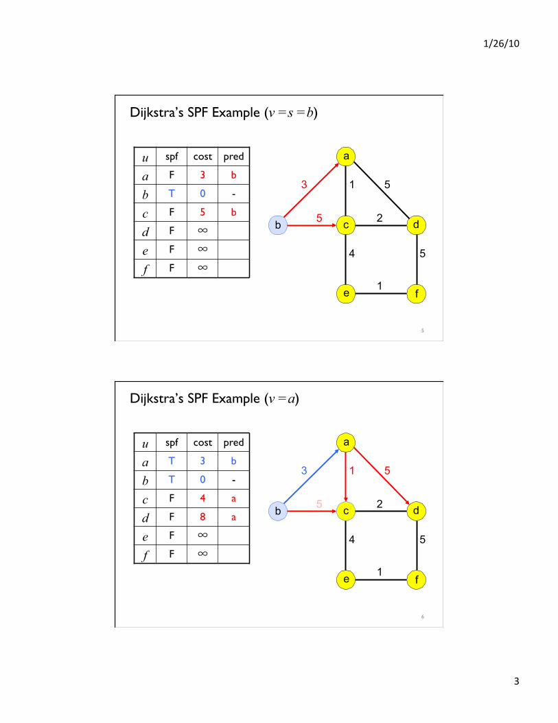
Dijkstra’s SPF Example (v =s =b)
u spf cost pred
a F 3 b
b T 0 -
c F 5 b
d F ∞
e F ∞
f F ∞
a
b c d
e f
3
5
1 5
1
5 4
2
5
Dijkstra’s SPF Example (v =a)
u spf cost pred
a T 3 b
b T 0 -
c F 4 a
d F 8 a
e F ∞
f F ∞
a
b c d
e f
3
5
1 5
1
5 4
2
6
1/26/10
4
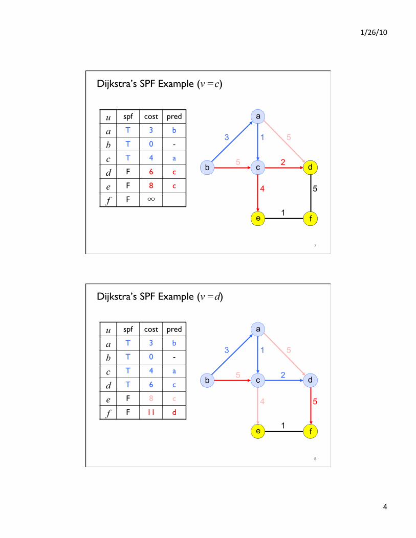
Dijkstra’s SPF Example (v =c)
u spf cost pred
a T 3 b
b T 0 -
c T 4 a
d F 6 c
e F 8 c
f F ∞
a
b c d
e f
3
5
1 5
1
5 4
2
7
Dijkstra’s SPF Example (v =d)
u spf cost pred
a T 3 b
b T 0 -
c T 4 a
d T 6 c
e F 8 c
f F 11 d
a
b c d
e f
3
5
1 5
1
5 4
2
8
1/26/10
5
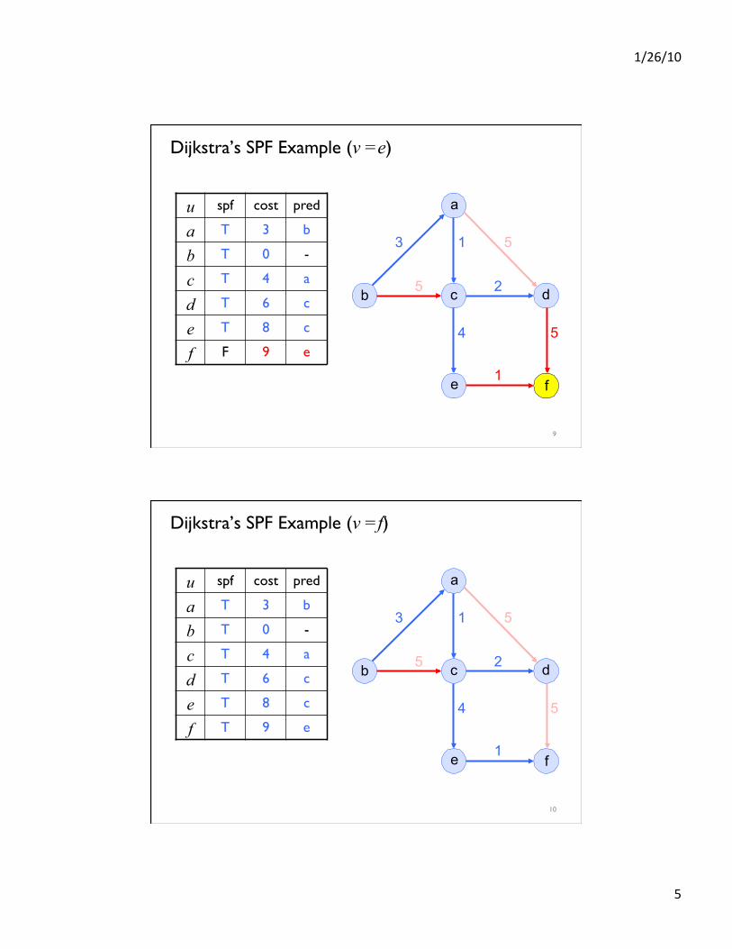
Dijkstra’s SPF Example (v =e)
u spf cost pred
a T 3 b
b T 0 -
c T 4 a
d T 6 c
e T 8 c
f F 9 e
a
b c d
e f
3
5
1 5
1
5 4
2
9
Dijkstra’s SPF Example (v =f)
u spf cost pred
a T 3 b
b T 0 -
c T 4 a
d T 6 c
e T 8 c
f T 9 e
a
b c d
e f
3
5
1 5
1
5 4
2
10
1/26/10
6
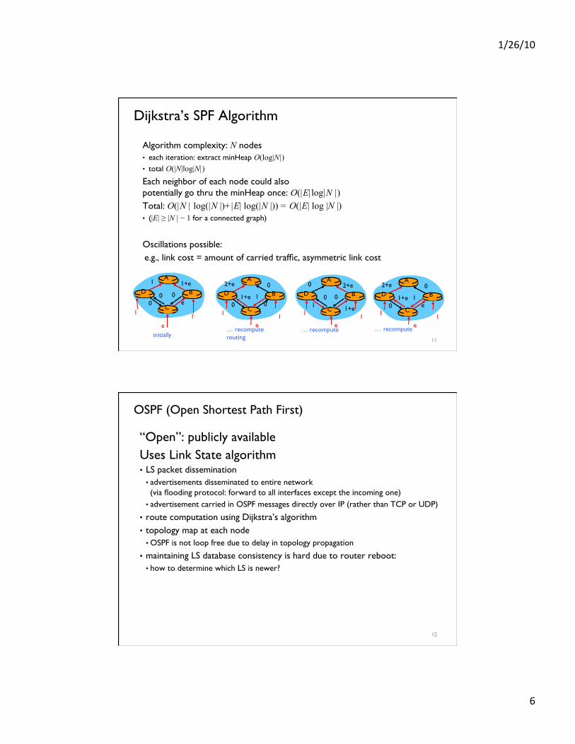
Dijkstra’s SPF Algorithm
Algorithm complexity: N nodes • each iteration: extract minHeap O(log|N|) • total O(|N|log|N|) Each neighbor of each node could also ���potentially go thru the minHeap once: O(|E|log|N |) Total: O(|N | log(|N |)+|E| log(|N |)) = O(|E| log |N |) • (|E| ≥ |N | − 1 for a connected graph)
Oscillations possible: e.g., link cost = amount of carried traffic, asymmetric link cost
A
D
C
B
1 1+e
e 0
e
1 1
0 0
A
D
C
B
2+e 0
0 0 1+e 1
A
D
C
B
0 2+e
1+e 1 0 0
A
D
C
B
2+e 0
e 0 1+e 1
initially … recompute routing
… recompute … recompute
1 1 1 1 1 1 e e e
11
OSPF (Open Shortest Path First)
“Open”: publicly available Uses Link State algorithm • LS packet dissemination
• advertisements disseminated to entire network ���(via flooding protocol: forward to all interfaces except the incoming one)
• advertisement carried in OSPF messages directly over IP (rather than TCP or UDP)
• route computation using Dijkstra’s algorithm • topology map at each node
• OSPF is not loop free due to delay in topology propagation
• maintaining LS database consistency is hard due to router reboot: • how to determine which LS is newer?
12
1/26/10
7
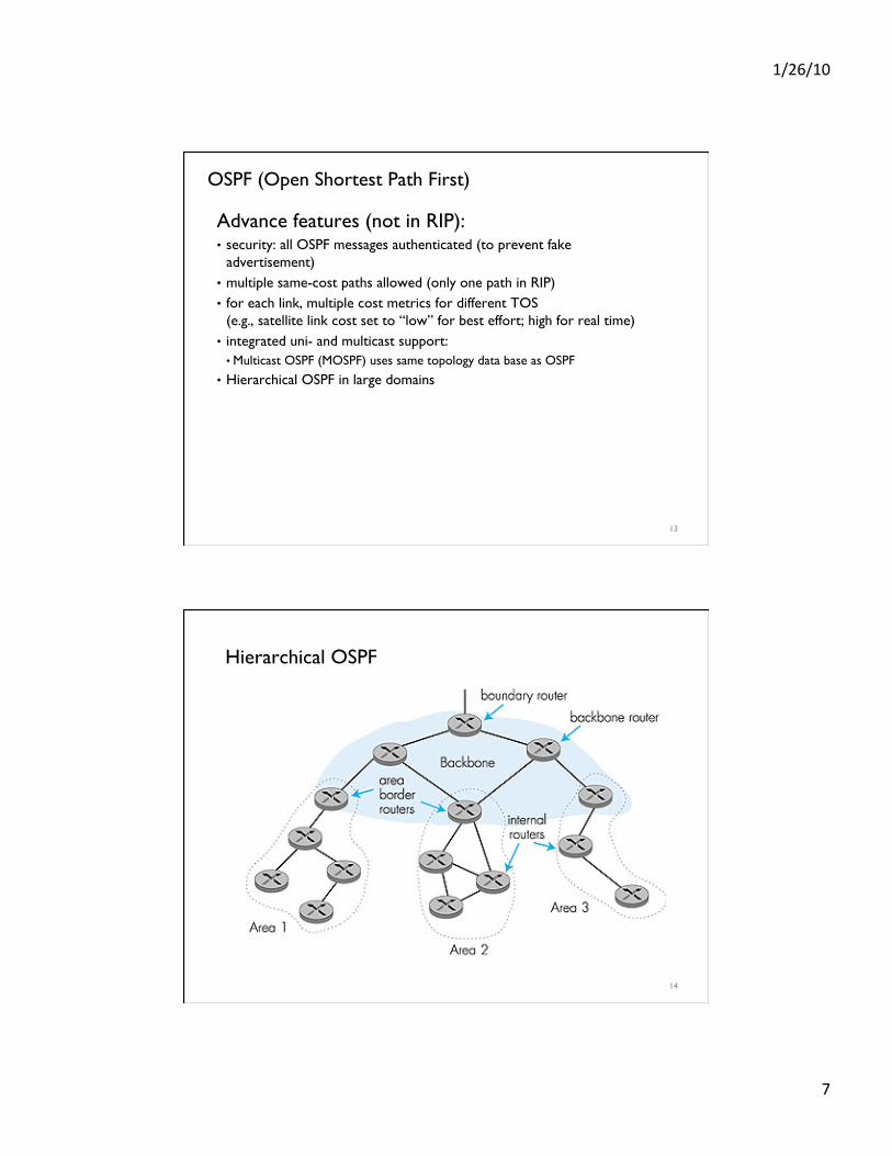
OSPF (Open Shortest Path First)
Advance features (not in RIP): • security: all OSPF messages authenticated (to prevent fake
advertisement) • multiple same-cost paths allowed (only one path in RIP) • for each link, multiple cost metrics for different TOS ���
(e.g., satellite link cost set to “low” for best effort; high for real time) • integrated uni- and multicast support:
• Multicast OSPF (MOSPF) uses same topology data base as OSPF
• Hierarchical OSPF in large domains
13
Hierarchical OSPF
14
1/26/10
8
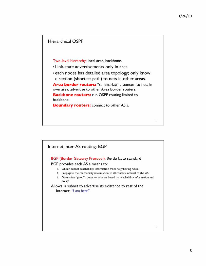
Hierarchical OSPF
Two-level hierarchy: local area, backbone.
• Link-state advertisements only in area • each nodes has detailed area topology; only know direction (shortest path) to nets in other areas.
Area border routers: “summarize” distances to nets in own area, advertise to other Area Border routers. Backbone routers: run OSPF routing limited to backbone. Boundary routers: connect to other AS’s.
15
Internet inter-AS routing: BGP
BGP (Border Gateway Protocol): the de facto standard BGP provides each AS a means to:
1. Obtain subnet reachability information from neighboring ASes. 2. Propagate the reachability information to all routers internal to the AS. 3. Determine “good” routes to subnets based on reachability information and
policy.
Allows a subnet to advertise its existence to rest of the Internet: “I am here”
16
1/26/10
9
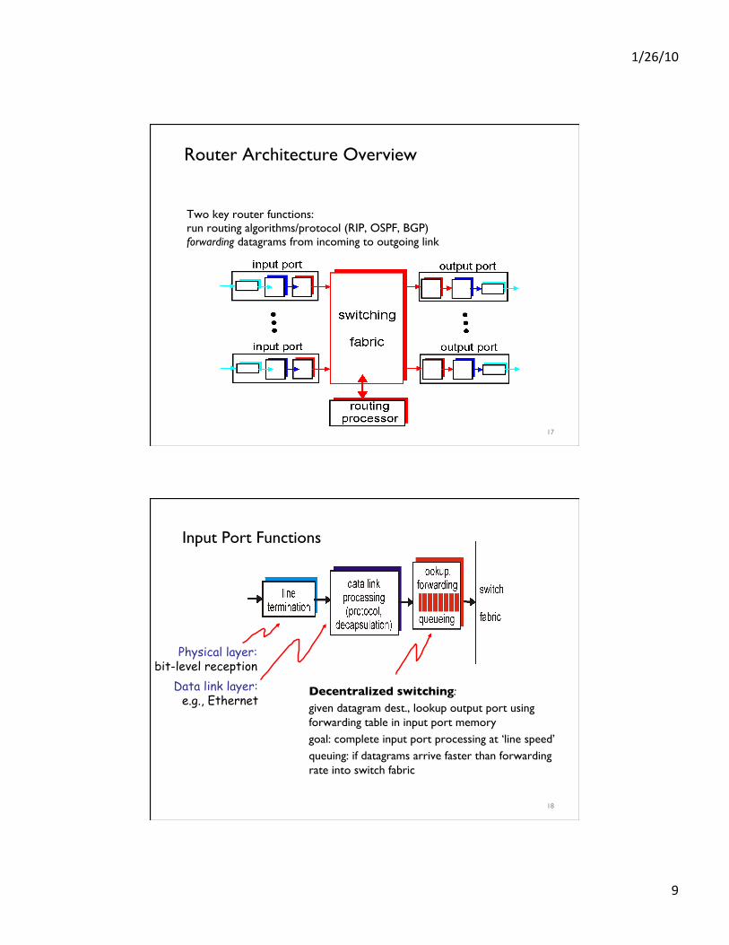
Router Architecture Overview
Two key router functions: run routing algorithms/protocol (RIP, OSPF, BGP) forwarding datagrams from incoming to outgoing link
17
Input Port Functions
Decentralized switching: given datagram dest., lookup output port using forwarding table in input port memory goal: complete input port processing at ‘line speed’ queuing: if datagrams arrive faster than forwarding rate into switch fabric
Physical layer: bit-level reception
Data link layer: e.g., Ethernet
18
1/26/10
10
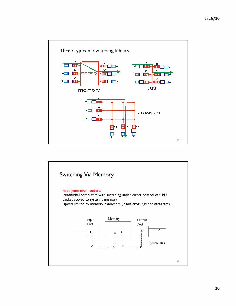
Three types of switching fabrics
19
Switching Via Memory
First generation routers: traditional computers with switching under direct control of CPU packet copied to system’s memory speed limited by memory bandwidth (2 bus crossings per datagram)
Input Port Output
Port Memory
System Bus
20
1/26/10
11
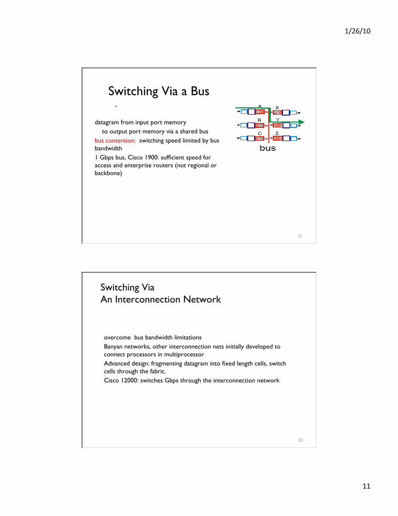
Switching Via a Bus
datagram from input port memory to output port memory via a shared bus bus contention: switching speed limited by bus bandwidth 1 Gbps bus, Cisco 1900: sufficient speed for access and enterprise routers (not regional or backbone)
21
Switching Via ���An Interconnection Network
overcome bus bandwidth limitations Banyan networks, other interconnection nets initially developed to connect processors in multiprocessor Advanced design: fragmenting datagram into fixed length cells, switch cells through the fabric. Cisco 12000: switches Gbps through the interconnection network
22
1/26/10
12
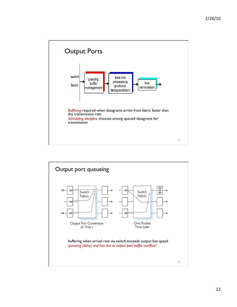
Output Ports
Buffering required when datagrams arrive from fabric faster than the transmission rate Scheduling discipline chooses among queued datagrams for transmission
23
Output port queueing
buffering when arrival rate via switch exceeds output line speed queueing (delay) and loss due to output port buffer overflow!
24
1/26/10
13
How much buffering?
RFC 3439 rule of thumb: average buffering equal to “typical” RTT (say 250 msec) times link capacity C • e.g., C = 10 Gps link: 2.5 Gbit buffer
Recent recommendation: with N flows, buffering equal to RTT C . N
25
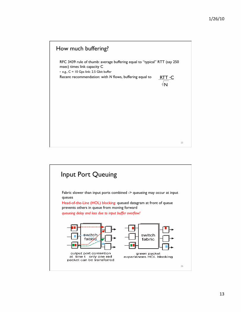
Input Port Queuing
Fabric slower than input ports combined -> queueing may occur at input queues Head-of-the-Line (HOL) blocking: queued datagram at front of queue prevents others in queue from moving forward queueing delay and loss due to input buffer overflow!
26
1/26/10
14
DHCP: Dynamic Host Configuration Protocol
Goal: allow host to dynamically obtain its IP address from network server when it joins network Can renew its lease on address in use Allows reuse of addresses (only hold address while connected an “on”) Support for mobile users who want to join network (more shortly)
DHCP overview: • host broadcasts “DHCP discover” msg [optional]
• DHCP server responds with “DHCP offer” msg [optional] • host requests IP address: “DHCP request” msg
• DHCP server sends address: “DHCP ack” msg
27
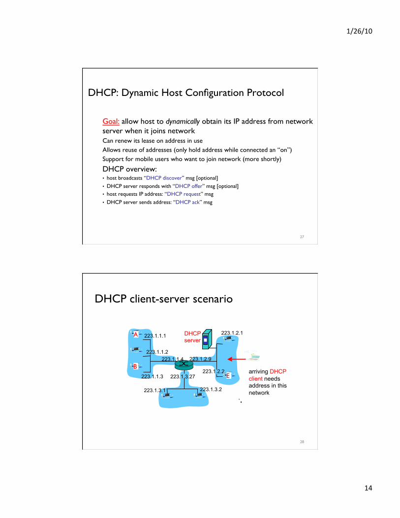
DHCP client-server scenario
223.1.1.1
223.1.1.2
223.1.1.3
223.1.1.4 223.1.2.9
223.1.2.2
223.1.2.1
223.1.3.2 223.1.3.1
223.1.3.27
A
B E
DHCP server
arriving DHCP client needs address in this network
28
1/26/10
15
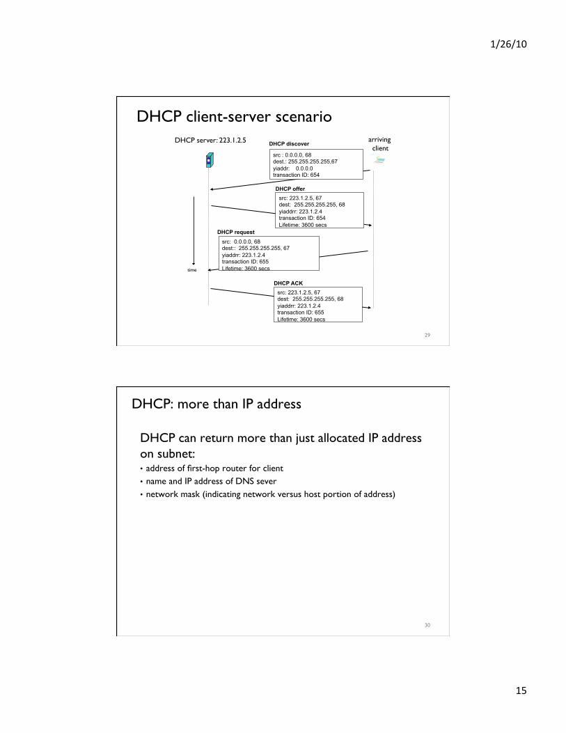
DHCP client-server scenario DHCP server: 223.1.2.5 arriving
client
time
DHCP discover
src : 0.0.0.0, 68 dest.: 255.255.255.255,67 yiaddr: 0.0.0.0 transaction ID: 654
DHCP offer src: 223.1.2.5, 67 dest: 255.255.255.255, 68 yiaddrr: 223.1.2.4 transaction ID: 654 Lifetime: 3600 secs
DHCP request src: 0.0.0.0, 68 dest:: 255.255.255.255, 67 yiaddrr: 223.1.2.4 transaction ID: 655 Lifetime: 3600 secs
DHCP ACK src: 223.1.2.5, 67 dest: 255.255.255.255, 68 yiaddrr: 223.1.2.4 transaction ID: 655 Lifetime: 3600 secs
29
DHCP: more than IP address
DHCP can return more than just allocated IP address on subnet: • address of first-hop router for client • name and IP address of DNS sever • network mask (indicating network versus host portion of address)
30
1/26/10
16
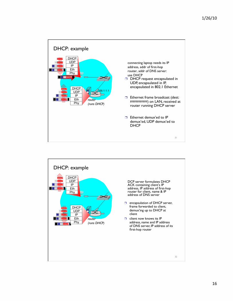
DHCP: example
connecting laptop needs its IP address, addr of first-hop router, addr of DNS server: use DHCP
router (runs DHCP)
DHCP UDP
IP Eth Phy
DHCP
DHCP
DHCP
DHCP
DHCP
DHCP UDP
IP Eth Phy
DHCP
DHCP
DHCP
DHCP DHCP
❒ DHCP request encapsulated in UDP, encapsulated in IP, encapsulated in 802.1 Ethernet
❒ Ethernet frame broadcast (dest: FFFFFFFFFFFF) on LAN, received at router running DHCP server
❒ Ethernet demux’ed to IP demux’ed, UDP demux’ed to DHCP
168.1.1.1
31
DCP server formulates DHCP ACK containing client’s IP address, IP address of first-hop router for client, name & IP address of DNS server
router (runs DHCP)
DHCP UDP
IP Eth Phy
DHCP
DHCP
DHCP
DHCP
DHCP UDP
IP Eth Phy
DHCP
DHCP
DHCP
DHCP
DHCP
❒ encapsulation of DHCP server, frame forwarded to client, demux’ing up to DHCP at client
❒ client now knows its IP address, name and IP address of DNS server, IP address of its first-hop router
DHCP: example
32
1/26/10
17
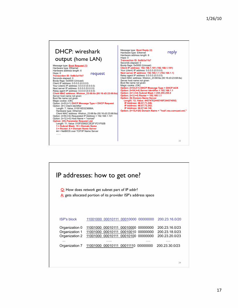
DHCP: wireshark output (home LAN)
Message type: Boot Reply (2) Hardware type: Ethernet Hardware address length: 6 Hops: 0 Transaction ID: 0x6b3a11b7 Seconds elapsed: 0 Bootp flags: 0x0000 (Unicast) Client IP address: 192.168.1.101 (192.168.1.101) Your (client) IP address: 0.0.0.0 (0.0.0.0) Next server IP address: 192.168.1.1 (192.168.1.1) Relay agent IP address: 0.0.0.0 (0.0.0.0) Client MAC address: Wistron_23:68:8a (00:16:d3:23:68:8a) Server host name not given Boot file name not given Magic cookie: (OK) Option: (t=53,l=1) DHCP Message Type = DHCP ACK Option: (t=54,l=4) Server Identifier = 192.168.1.1 Option: (t=1,l=4) Subnet Mask = 255.255.255.0 Option: (t=3,l=4) Router = 192.168.1.1 Option: (6) Domain Name Server Length: 12; Value: 445747E2445749F244574092; IP Address: 68.87.71.226; IP Address: 68.87.73.242; IP Address: 68.87.64.146 Option: (t=15,l=20) Domain Name = "hsd1.ma.comcast.net."
reply
Message type: Boot Request (1) Hardware type: Ethernet Hardware address length: 6 Hops: 0 Transaction ID: 0x6b3a11b7 Seconds elapsed: 0 Bootp flags: 0x0000 (Unicast) Client IP address: 0.0.0.0 (0.0.0.0) Your (client) IP address: 0.0.0.0 (0.0.0.0) Next server IP address: 0.0.0.0 (0.0.0.0) Relay agent IP address: 0.0.0.0 (0.0.0.0) Client MAC address: Wistron_23:68:8a (00:16:d3:23:68:8a) Server host name not given Boot file name not given Magic cookie: (OK) Option: (t=53,l=1) DHCP Message Type = DHCP Request Option: (61) Client identifier Length: 7; Value: 010016D323688A; Hardware type: Ethernet Client MAC address: Wistron_23:68:8a (00:16:d3:23:68:8a) Option: (t=50,l=4) Requested IP Address = 192.168.1.101 Option: (t=12,l=5) Host Name = "nomad" Option: (55) Parameter Request List Length: 11; Value: 010F03062C2E2F1F21F92B 1 = Subnet Mask; 15 = Domain Name 3 = Router; 6 = Domain Name Server 44 = NetBIOS over TCP/IP Name Server ……
request
33
IP addresses: how to get one?
Q: How does network get subnet part of IP addr? A: gets allocated portion of its provider ISP’s address space
ISP's block 11001000 00010111 00010000 00000000 200.23.16.0/20
Organization 0 11001000 00010111 00010000 00000000 200.23.16.0/23 Organization 1 11001000 00010111 00010010 00000000 200.23.18.0/23 Organization 2 11001000 00010111 00010100 00000000 200.23.20.0/23 ... ….. …. …. Organization 7 11001000 00010111 00011110 00000000 200.23.30.0/23
34
1/26/10
18
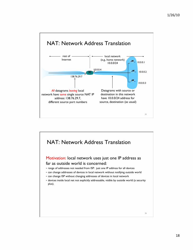
NAT: Network Address Translation
10.0.0.1
10.0.0.2
10.0.0.3
10.0.0.4
138.76.29.7
local network (e.g., home network)
10.0.0/24
rest of Internet
Datagrams with source or destination in this network have 10.0.0/24 address for
source, destination (as usual)
All datagrams leaving local network have same single source NAT IP
address: 138.76.29.7, different source port numbers
35
NAT: Network Address Translation
Motivation: local network uses just one IP address as far as outside world is concerned: • range of addresses not needed from ISP: just one IP address for all devices • can change addresses of devices in local network without notifying outside world • can change ISP without changing addresses of devices in local network • devices inside local net not explicitly addressable, visible by outside world (a security
plus).
36
1/26/10
19
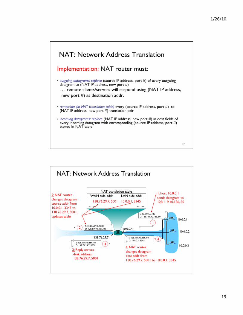
NAT: Network Address Translation
Implementation: NAT router must: ���
• outgoing datagrams: replace (source IP address, port #) of every outgoing datagram to (NAT IP address, new port #) . . . remote clients/servers will respond using (NAT IP address, new port #) as destination addr. ���
• remember (in NAT translation table) every (source IP address, port #) to (NAT IP address, new port #) translation pair���
• incoming datagrams: replace (NAT IP address, new port #) in dest fields of every incoming datagram with corresponding (source IP address, port #) stored in NAT table
37
NAT: Network Address Translation
10.0.0.1
10.0.0.2
10.0.0.3
S: 10.0.0.1, 3345 D: 128.119.40.186, 80
1
10.0.0.4
138.76.29.7
1: host 10.0.0.1 sends datagram to 128.119.40.186, 80
NAT translation table WAN side addr LAN side addr
138.76.29.7, 5001 10.0.0.1, 3345 …… ……
S: 128.119.40.186, 80 D: 10.0.0.1, 3345 4
S: 138.76.29.7, 5001 D: 128.119.40.186, 80 2
2: NAT router changes datagram source addr from 10.0.0.1, 3345 to 138.76.29.7, 5001, updates table
S: 128.119.40.186, 80 D: 138.76.29.7, 5001 3
3: Reply arrives dest. address: 138.76.29.7, 5001
4: NAT router changes datagram dest addr from 138.76.29.7, 5001 to 10.0.0.1, 3345
1/26/10
20
NAT: Network Address Translation
16-bit port-number field: • 60,000 simultaneous connections with a single LAN-side address!
NAT is controversial: • routers should only process up to layer 3 • violates end-to-end argument
• NAT possibility must be taken into account by app designers, eg, P2P applications
• address shortage should instead be solved by IPv6
39
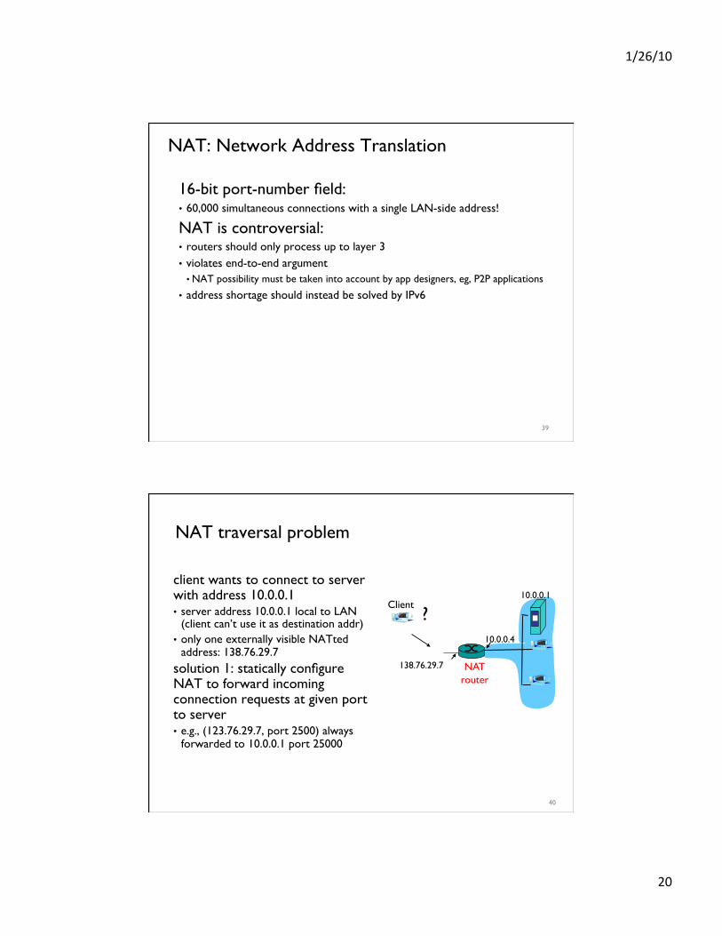
NAT traversal problem
client wants to connect to server with address 10.0.0.1 • server address 10.0.0.1 local to LAN
(client can’t use it as destination addr) • only one externally visible NATted
address: 138.76.29.7 solution 1: statically configure NAT to forward incoming connection requests at given port to server • e.g., (123.76.29.7, port 2500) always
forwarded to 10.0.0.1 port 25000
10.0.0.1
10.0.0.4
NAT router
138.76.29.7
Client ?
40
1/26/10
21
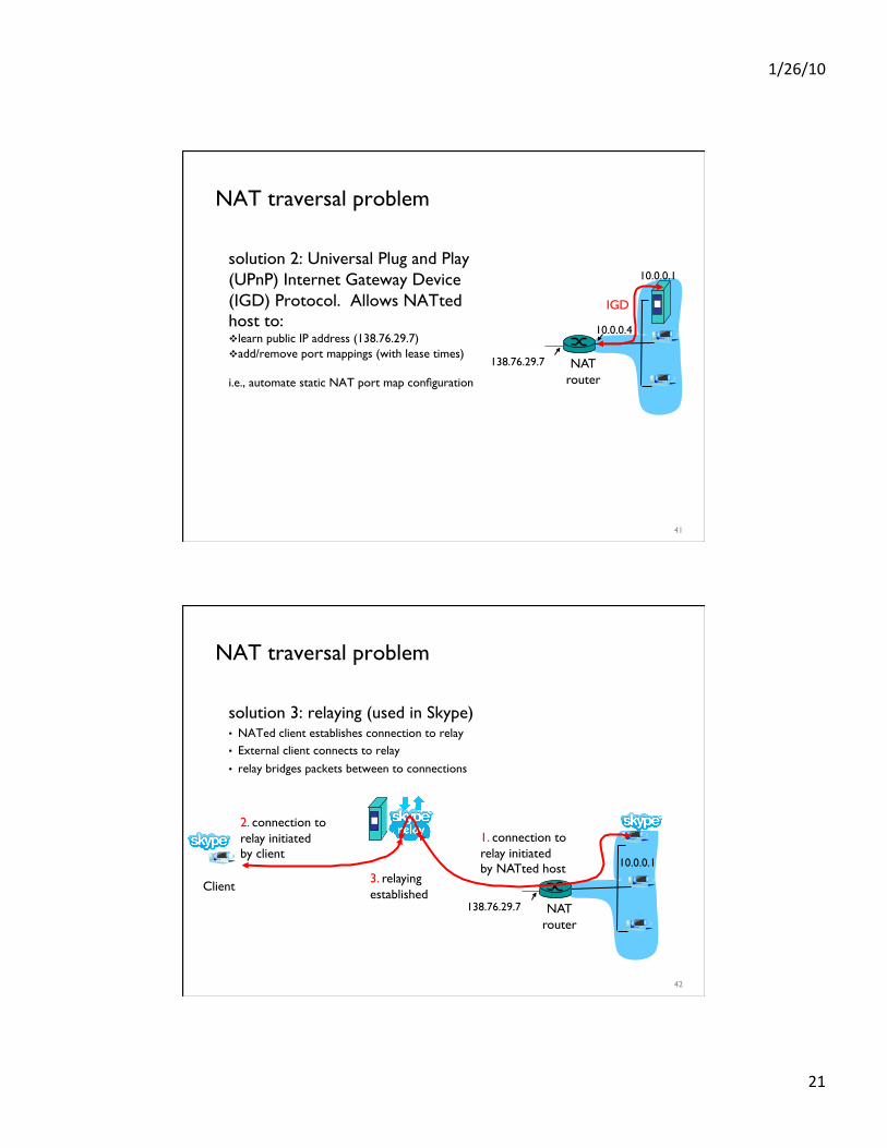
NAT traversal problem
solution 2: Universal Plug and Play (UPnP) Internet Gateway Device (IGD) Protocol. Allows NATted host to: learn public IP address (138.76.29.7) add/remove port mappings (with lease times)
i.e., automate static NAT port map configuration
10.0.0.1
10.0.0.4
NAT router
138.76.29.7
IGD
41
NAT traversal problem
solution 3: relaying (used in Skype) • NATed client establishes connection to relay • External client connects to relay
• relay bridges packets between to connections
138.76.29.7
Client
10.0.0.1
NAT router
1. connection to relay initiated by NATted host
2. connection to relay initiated by client
3. relaying established
42