Embed Size (px)
Citation preview
LMF
LaminarMasterFlow SYSTEM
Reference Book
This reference book is solely aimed to qualified employees, who have achieved the necessary knowledge with regard to language
understanding and contents.
The separate manual includes all information relevant for the operator.
The following text is a translation of the source document from the German language.
*** VERSION 7.0 *** Status: 2019-02-13
Reference Manual LMF
Page ii LMF V7.0
Copyright
The copyright of this operating instructions remains with TetraTec Instruments GmbH Gewerbestr. 8 D-71144 Steinenbronn This operating instructions are determined only for the operator and its staff. Included are regulations and notes, which must not be • duplicated • spread • or otherwise communicated either partly or completely. Violations may result in prosecution.
Service
If there are any questions exceeding the contents of the provided product information, you may contact us at the address indicated above. Telephone: 0049 - 7157 / 5387-0 Telefax: 0049 - 7157 / 5387-10 Email: [email protected] In addition, you will find more information and data sheets of other products at our homepage: You are invited to visit www.tetratec.de.
Reference Manual LMF
LMF V7.0 Page iii
Table of Contents
1 INTRODUCTION ............................................................................................................................ 1
1.1 Product Description .................................................................................................................. 1 1.1.1 Hardware ................................................................................................................................. 1 1.1.2 Software .................................................................................................................................. 1
1.2 Intended use .............................................................................................................................. 1
1.3 Warranty and Liability ............................................................................................................... 3
2 SAFETY .......................................................................................................................................... 4
2.1 Basic Safety Instructions ......................................................................................................... 4 2.1.1 Responsibility of the Operator ................................................................................................. 4 2.1.2 Responsibility of the Staff ........................................................................................................ 4 2.1.3 Inevitable Remaining Dangers by the Equipment ................................................................... 5 2.1.4 Switch-on characteristics with running PLC ............................................................................ 6
2.2 Notes for set-up, installation and operation of the equipment ............................................. 6 2.2.1 Set-up, Installation .................................................................................................................. 6 2.2.2 Operating Conditions, Ambient Conditions ............................................................................. 7 2.2.3 Power supply, electric connection of systems with mains connection .................................... 7 2.2.4 Cleaning of the system ............................................................................................................ 7 2.2.5 Calibration, measuring accuracy ............................................................................................. 7 2.2.6 Structural changes on systems and measuring sections ........................................................ 8 2.2.7 Limit parameter access ........................................................................................................... 8
3 COMPONENTS OF A LMF SYSTEM .......................................................................................... 10
3.1 Overview ...................................................................................................................................10
3.2 Primary elements .....................................................................................................................11 3.2.1 Active pressure transmitter ...................................................................................................11 3.2.2 Counter ..................................................................................................................................12 3.2.3 Miscellaneous .......................................................................................................................12
4 OPERATIONAL CONTROLS ...................................................................................................... 13
4.1 Front panel operational controls of the controller S320 .....................................................13
4.2 Interfaces of the controller S320 ............................................................................................15
4.3 Additional front panel operational controls with installation in a horizontal 19” case ....16
4.4 Interfaces on the backside with installation in a horizontal 19” case ...............................17
5 INTERFACES FOR REMOTE CONTROL ................................................................................... 18
5.1 Set up RS232 interface............................................................................................................19 5.1.1 Default settings in the configuration file: ...............................................................................19 5.1.2 Interface settings in the terminal program .............................................................................19 5.1.3 Test function of the serial interface .......................................................................................19 5.1.4 Test function of the link interface ..........................................................................................20
5.2 Set up network interface .........................................................................................................20 5.2.1 Change the IP address of the LMF .......................................................................................20 5.2.2 Port Number of Link-Interface ...............................................................................................20 5.2.3 Port Number of Comm-Interface ...........................................................................................20 5.2.4 Usage of IP address and port number in the terminal program ............................................20 5.2.5 Test connection .....................................................................................................................21 5.2.6 Access restrictions ................................................................................................................21
Reference Manual LMF
Page iv LMF V7.0
5.3 Query and change of parameters ..........................................................................................22 5.3.1 Physical units ........................................................................................................................22 5.3.2 Query parameters .................................................................................................................22 5.3.3 Change parameters: .............................................................................................................23
5.4 Virtual inputs and outputs ......................................................................................................24 5.4.1 Communication .....................................................................................................................24 5.4.2 Timeouts................................................................................................................................24 5.4.3 Access control .......................................................................................................................24
5.5 List of the remote control commands of the Comm interface ............................................25 5.5.1 ACTIVATE .............................................................................................................................25 5.5.2 AKSEND................................................................................................................................25 5.5.3 CACHECTRL ........................................................................................................................25 5.5.4 CONTROL .............................................................................................................................25 5.5.5 DATE .....................................................................................................................................26 5.5.6 DEFAULTS............................................................................................................................26 5.5.7 DIR ........................................................................................................................................26 5.5.8 DISCARD ..............................................................................................................................26 5.5.9 DLIST ....................................................................................................................................26 5.5.10 DMODE .............................................................................................................................27 5.5.11 DPAGE .............................................................................................................................27 5.5.12 DUMP ...............................................................................................................................27 5.5.13 EDITMENU .......................................................................................................................27 5.5.14 EVAL .................................................................................................................................28 5.5.15 EXTFUNC .........................................................................................................................28 5.5.16 FACDBG ...........................................................................................................................28 5.5.17 FILTER ..............................................................................................................................28 5.5.18 FLIPFLOP .........................................................................................................................28 5.5.19 GASMIX ............................................................................................................................29 5.5.20 HASDEFAULTS ................................................................................................................29 5.5.21 HEAPINFO ........................................................................................................................29 5.5.22 HELP .................................................................................................................................29 5.5.23 HIGHSPEED .....................................................................................................................30 5.5.24 HWERROR .......................................................................................................................30 5.5.25 INPUT ...............................................................................................................................31 5.5.26 IVALVE .............................................................................................................................31 5.5.27 IZERO ...............................................................................................................................31 5.5.28 LASTSTATES ...................................................................................................................31 5.5.29 LEAK .................................................................................................................................32 5.5.30 LOAD ................................................................................................................................32 5.5.31 LOGLEVEL .......................................................................................................................32 5.5.32 MEAS ................................................................................................................................32 5.5.33 MELE ................................................................................................................................32 5.5.34 NCOMBI ............................................................................................................................32 5.5.35 OUTPUT ...........................................................................................................................33 5.5.36 PRIMARY ..........................................................................................................................33 5.5.37 PROG ...............................................................................................................................34 5.5.38 PROGMENU .....................................................................................................................34 5.5.39 QUIT .................................................................................................................................34 5.5.40 RATING ............................................................................................................................34 5.5.41 RPAR ................................................................................................................................35 5.5.42 RUN ..................................................................................................................................35 5.5.43 SAVE ................................................................................................................................35 5.5.44 SCRIPTINFO ....................................................................................................................35 5.5.45 SISEND .............................................................................................................................35 5.5.46 STOP ................................................................................................................................36 5.5.47 SUBPROG ........................................................................................................................36 5.5.48 SUBS ................................................................................................................................36 5.5.49 Temp .................................................................................................................................36 5.5.50 TESTMENU ......................................................................................................................36
Reference Manual LMF
LMF V7.0 Page v
5.5.51 TIMESTAT ........................................................................................................................36 5.5.52 VERS ................................................................................................................................36 5.5.53 ZERO ................................................................................................................................36
5.6 AK protocol ..............................................................................................................................37 5.6.1 Structure of the protocol ........................................................................................................37 5.6.2 Reaction to not executable commands .................................................................................39 5.6.3 APAR .....................................................................................................................................40 5.6.4 ASTF .....................................................................................................................................40 5.6.5 ASTZ .....................................................................................................................................41 5.6.6 EPAR .....................................................................................................................................42 5.6.7 SACK .....................................................................................................................................42 5.6.8 SACT .....................................................................................................................................43 5.6.9 SMAN ....................................................................................................................................43 5.6.10 SPRG ................................................................................................................................43 5.6.11 SREM ................................................................................................................................44 5.6.12 SRUN ................................................................................................................................44 5.6.13 SSTP .................................................................................................................................44
6 SYNTAX ....................................................................................................................................... 45
6.1 Figure formats for the input of numerical parameter values ..............................................45
6.2 Format strings for protocol printout functions ....................................................................45
6.3 Control terms ...........................................................................................................................46 6.3.1 Types .....................................................................................................................................46 6.3.2 Operators and their priorities.................................................................................................47 6.3.3 Variables ...............................................................................................................................48 6.3.4 Fields .....................................................................................................................................49 6.3.5 Functions ...............................................................................................................................50
7 OPERATING MODES .................................................................................................................. 51
7.1 STANDARD MODE ...................................................................................................................51 7.1.1 Program selection .................................................................................................................51
7.2 LEAK TESTING ........................................................................................................................51
7.3 MEASUREMENT with taking the mean ..................................................................................52
7.4 Special modes for the experienced user ..............................................................................52 7.4.1 Test mode .............................................................................................................................52 7.4.2 Nullification ............................................................................................................................53 7.4.3 Editing mode .........................................................................................................................54
8 PARAMETER STRUCTURE ........................................................................................................ 56
8.1 Parameter structure und Overview ........................................................................................56 8.1.1 C parameter nozzle combinations ........................................................................................56 8.1.2 D parameter display configurations ......................................................................................56 8.1.3 E parameter extension flow elements ...................................................................................56 8.1.4 F parameter: freely usable float parameters .........................................................................56 8.1.5 H parameter functions ...........................................................................................................56 8.1.6 I parameter: freely usable integer parameters ......................................................................56 8.1.7 M parameter - gas mixtures and mechanical elements ........................................................56 8.1.8 P parameter – measuring programs .....................................................................................57 8.1.9 R parameter - read parameter, measurement results of the measuring programs ..............58 8.1.10 S parameter – system parameter .....................................................................................59 8.1.11 U parameter – sub programs ............................................................................................59
Reference Manual LMF
Page vi LMF V7.0
9 PARAMETER LIST ...................................................................................................................... 60
9.1 C parameter: Nozzle combinations .......................................................................................60
9.2 D parameter: Display lists ......................................................................................................60 9.2.1 D0000-D0019 block: Linkage program mode with display list ..............................................60 9.2.2 D0100-D0499 block: Linkage of display pages to a display list ............................................61 9.2.3 D1000-D1999 block: Definitions of the display pages ..........................................................62
9.3 E parameter: Extension primary elements ...........................................................................63
9.4 F and I parameter: Freely usable parameters .......................................................................63
9.5 H parameter: Functions ..........................................................................................................63 9.5.1 H0000-H0499 block: Switching over vectors ........................................................................63 9.5.2 H1000-H2999 block: External, parameterizable functions ....................................................63 9.5.3 H5000-H6999 block: External, parameterizable filters .........................................................65 9.5.4 H7000 block: User-defined units ...........................................................................................66
9.6 M parameter: Gas mixtures ....................................................................................................67 9.6.1 M0xxx block: Definition of gas mixtures ................................................................................67 9.6.2 M1xxx block: Mechanical Elements ......................................................................................68
9.7 S parameter: System parameter ............................................................................................69 9.7.1 S0000 block: general parameters .........................................................................................69 9.7.2 S0350 block: Error conditions of inputs and outputs ............................................................72 9.7.3 S0500 block: User administration .........................................................................................73 9.7.4 S1000 block: Preselection of program ..................................................................................73 9.7.5 S1100 block: Stabilization periods nullification .....................................................................74 9.7.6 S1200 block: Flip-flops (flags) ...............................................................................................74 9.7.7 S1300 block: Virtual outputs .................................................................................................75 9.7.8 S1400 block: PLC control inputs ...........................................................................................75 9.7.9 S1500 block: Input/output allocations ...................................................................................76 9.7.10 S1600 block: Impulse valves ............................................................................................77 9.7.11 S1800 block: Digital outputs .............................................................................................77 9.7.12 S2000/S3000 block: Linearization of sensors ..................................................................78 9.7.13 Extended parameter set for integrated analogue inputs ..................................................80 9.7.14 Extended parameter set for serial analogue inputs ..........................................................80 9.7.15 Extended parameters set for R parameter as inputs ........................................................80 9.7.16 Extended parameter set for integrated frequency inputs .................................................81 9.7.17 Extended parameter set for integrated counter inputs .....................................................81 9.7.18 S4000-S7000 block: Linearization of primary elements ...................................................82 9.7.19 Extended parameters set for direct inputs ........................................................................83 9.7.20 Extended parameter set for leakage measuring (LMS) ....................................................83 9.7.21 Extended parameter set for critical nozzles ......................................................................83 9.7.22 Extended parameter set for orifices, Venturi-Elements, Betaflows and SAO nozzles .....84 9.7.23 Extended parameter set for accutubes .............................................................................84 9.7.24 Extended parameter set for gas meters ...........................................................................85 9.7.25 S8000 block: Scaling of analogue outputs .......................................................................85 9.7.26 Extended parameter set for integrated analogue outputs ................................................85 9.7.27 Extended parameter set for integrated frequency outputs ...............................................86 9.7.28 Extended parameter set for integrated PWM outputs ......................................................86 9.7.29 S9000 block: Special functions .........................................................................................86 9.7.30 S9010 block: System absolute pressure ..........................................................................87 9.7.31 S9100-Block: Subscribe ...................................................................................................87 9.7.32 S9300 block: Protocol printout ..........................................................................................88 9.7.33 S9350 block: Type editor ..................................................................................................89 9.7.34 S9370 block: Serial display ...............................................................................................90 9.7.35 S9400 block: Publish ........................................................................................................91 9.7.36 S9500 block: Definition of connection for virtual inputs and outputs ................................92 9.7.37 S9600 block: Configuration AK interface ..........................................................................93 9.7.38 S9700 block: Process control ...........................................................................................94 9.7.39 S9800 block: Script code ..................................................................................................94
Reference Manual LMF
LMF V7.0 Page vii
9.8 P parameter: Definitions of measuring programs ...............................................................95 9.8.1 Pn000 block: Primary element, basis description .................................................................95 9.8.2 Pn010 block: Differential pressure (Pdif) ..............................................................................96 9.8.3 Pn020 block: Test pressure absolute (Pabs) ........................................................................96 9.8.4 Pn030 block: Measuring temperature (Tem) ........................................................................97 9.8.5 Pn040 block: Measurement humidity (Hum) .........................................................................97 9.8.6 Pn050 block: Reference pressure absolute (RPab) .............................................................98 9.8.7 Pn060 block: Reference temperature (RTem) ......................................................................98 9.8.8 Pn070 block: Reference humidity (RHum) ............................................................................99 9.8.9 Pn075 block: Auxiliary input 0 (Aux0) ...................................................................................99 9.8.10 Pn080 block: Auxiliary input 1 (Aux1) ...............................................................................99 9.8.11 Pn085 block: Auxiliary input 2 (Aux2) .............................................................................100 9.8.12 Pn090 block: Auxiliary input 3 (Aux3) .............................................................................100 9.8.13 Pn095 block: Auxiliary input 4 (Aux4) .............................................................................100 9.8.14 Pn100 block: Units and decimal places for quantities ....................................................101 9.8.15 Pn200 block: Units and decimal places for R parameters ..............................................102 9.8.16 Pn300 block: Reference and correction calculation .......................................................102 9.8.17 Pn310 block: Functions ..................................................................................................103 9.8.18 Pn350 block: Calculated R parameters ..........................................................................103 9.8.19 Pn400 and Pn450 blocks: Control ..................................................................................104 9.8.20 Pn500 block: Limit values ...............................................................................................106 9.8.21 Pn550 block: Automatic program toggle .........................................................................106 9.8.22 Pn700 block: Process times ...........................................................................................107 9.8.23 Pn800 block: Display parameters depending on the program .......................................107
9.9 U parameter: Sub programs .................................................................................................108
9.10 Ryxxx block: Read parameter, measurement results ........................................................111
10 BASIS UNITS – CONVERSION (X AND Y FACTORS) ............................................................ 120
11 INDICATIONS TO THE METHODS OF CALCULATION .......................................................... 124
11.1 Ideal gas law ..........................................................................................................................124
11.2 Correlation between the flow variables ...............................................................................125
11.3 Adjustable types of gas ........................................................................................................126
11.4 Density calculation ................................................................................................................126
11.5 Viscosity calculation .............................................................................................................127
11.6 Allocation of Sensors and Measurands ..............................................................................127 11.6.1 Measuring sensors .........................................................................................................129 11.6.2 Reference sensors ..........................................................................................................130 11.6.3 Auxiliary ..........................................................................................................................133
11.7 Correction calculations.........................................................................................................134 11.7.1 Correction calculations for the LMF ................................................................................134 11.7.2 Example: corrected mass flow ........................................................................................136 11.7.3 Calibration of the LMF with the help of calibration leaks ................................................137
12 LINEARIZATION OF SENSORS AND PRIMARY ELEMENTS ................................................ 138
12.1 Linearization of the analogous value sensors with analogous or serial output ............138
12.2 Linearization of primary elements .......................................................................................139 12.2.1 LFE according to Hagen-Poiseuille ................................................................................139 12.2.2 LFE according to Universal Flow ....................................................................................140 12.2.3 Overcritical nozzles according to DIN EN ISO 9300 ......................................................140 12.2.4 Gas meter .......................................................................................................................140 12.2.5 Orifices, Venturi tubes, Pitot tubes / Accutubes... ..........................................................140
13 ALLOCATION OF THE SENSORS AND PRIMARY ELEMENTS ............................................ 141
14 MEASURING AND CORRECTION PROCESSES .................................................................... 143
Reference Manual LMF
Page viii LMF V7.0
15 UNCERTAINTY OF MEASUREMENT BUDGET ...................................................................... 145
15.1 Basic considerations Qv, Qm, r(p, T, xv) ............................................................................145
15.2 Percentage of uncertainty caused by leakage in the test section design .......................145
15.3 Uncertainties of measurement on comparative measurements with Laminar Flow Elements:.............................................................................................................................................146
15.4 Uncertainties of measurement with comparative measurements with orifices: ............147
15.5 Uncertainties of measurement with comparative measurements with critical nozzles:148
16 PLC INTERFACE ....................................................................................................................... 149
16.1 Overview of test steps and procedures ..............................................................................149
16.2 Detailed information for the particular test steps ..............................................................150 16.2.1 Wait for PLC start ...........................................................................................................150 16.2.2 Program selection ...........................................................................................................150 16.2.3 Nullification ......................................................................................................................151 16.2.4 Pre-Fill .............................................................................................................................151 16.2.5 Fill ...................................................................................................................................151 16.2.6 Calm ................................................................................................................................151 16.2.7 Measurement ..................................................................................................................151 16.2.8 Venting ............................................................................................................................152 16.2.9 Wait for PLC stop ............................................................................................................152
16.3 Overview of the signals ........................................................................................................152 16.3.1 Control inputs ..................................................................................................................152 16.3.2 Control outputs................................................................................................................153 16.3.3 Status outputs .................................................................................................................153 16.3.4 Result outputs .................................................................................................................153 16.3.5 The signal “no error” .......................................................................................................153
16.4 Standard configuration of the PLC digital interface ..........................................................153
16.5 Schematic signal functions ..................................................................................................155 16.5.1 Regular testing schedule ................................................................................................155 16.5.2 Testing schedules with malfunction ................................................................................156
Reference Manual LMF
LMF V7.0 Page 1
1 Introduction
1.1 Product Description
The LMF system consists of hardware and software.
1.1.1 Hardware
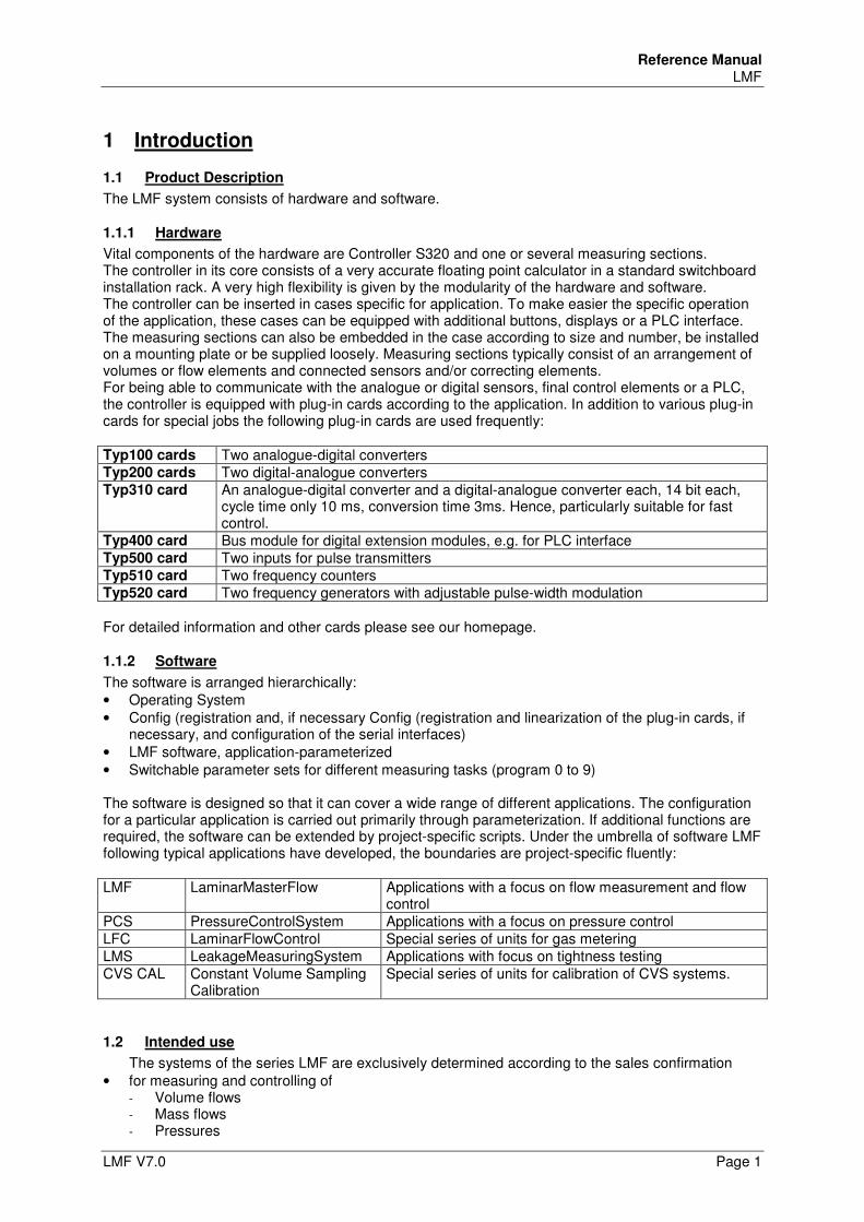
Vital components of the hardware are Controller S320 and one or several measuring sections. The controller in its core consists of a very accurate floating point calculator in a standard switchboard installation rack. A very high flexibility is given by the modularity of the hardware and software. The controller can be inserted in cases specific for application. To make easier the specific operation of the application, these cases can be equipped with additional buttons, displays or a PLC interface. The measuring sections can also be embedded in the case according to size and number, be installed on a mounting plate or be supplied loosely. Measuring sections typically consist of an arrangement of volumes or flow elements and connected sensors and/or correcting elements. For being able to communicate with the analogue or digital sensors, final control elements or a PLC, the controller is equipped with plug-in cards according to the application. In addition to various plug-in cards for special jobs the following plug-in cards are used frequently: Typ100 cards Two analogue-digital converters Typ200 cards Two digital-analogue converters Typ310 card An analogue-digital converter and a digital-analogue converter each, 14 bit each,
cycle time only 10 ms, conversion time 3ms. Hence, particularly suitable for fast control.
Typ400 card Bus module for digital extension modules, e.g. for PLC interface Typ500 card Two inputs for pulse transmitters Typ510 card Two frequency counters Typ520 card Two frequency generators with adjustable pulse-width modulation For detailed information and other cards please see our homepage.
1.1.2 Software
The software is arranged hierarchically: • Operating System • Config (registration and, if necessary Config (registration and linearization of the plug-in cards, if
necessary, and configuration of the serial interfaces) • LMF software, application-parameterized • Switchable parameter sets for different measuring tasks (program 0 to 9) The software is designed so that it can cover a wide range of different applications. The configuration for a particular application is carried out primarily through parameterization. If additional functions are required, the software can be extended by project-specific scripts. Under the umbrella of software LMF following typical applications have developed, the boundaries are project-specific fluently: LMF LaminarMasterFlow Applications with a focus on flow measurement and flow
control PCS PressureControlSystem Applications with a focus on pressure control LFC LaminarFlowControl Special series of units for gas metering LMS LeakageMeasuringSystem Applications with focus on tightness testing CVS CAL Constant Volume Sampling
Calibration Special series of units for calibration of CVS systems.
1.2 Intended use
The systems of the series LMF are exclusively determined according to the sales confirmation • for measuring and controlling of
- Volume flows - Mass flows - Pressures
Reference Manual LMF
Page 2 LMF V7.0
• For the calibration of other systems measuring and controlling such parameters • For metering of gaseous media • For leak testing Approved as a medium are (according to the sales confirmation) • Air • Gases
- Argon - Carbon dioxide - Carbon monoxide - Helium - Hydrogen - Nitrogen - Oxygen - Methane - Propane - N-butane - Natural gas - Laughing gas - Water vapor (as part of humid air) - Xenon - Nitrogen monoxide - Neon - Krypton - Propene - Ethane - Ethene - Ammonia - Sulfur dioxide
Note: The proper use is exclusively restricted to the application and the media specified in the sales confirmation. I.e., even the use for one of the purposes mentioned above and the operation with a medium mentioned above will be recognized as improper use, provided that the system has not been specified for that purpose! Tests and an approval in written form will be required with changes by TetraTec Instruments GmbH. When being used as a measuring unit in complex machines, a combination of machines, an assembly line or system, the signal outputs must exclusively be used for the information of a superior control (e.g. PLC. When being used as an independent laboratory measuring instrument with control function the regulations and indications for emergency stop functions and for the recovery of voltage after power failure must be observed. Intended use also includes • observing of all notes of the operating instructions • the compliance of the inspection and maintenance work. Another use or a use beyond that will be considered as not intended. TetraTec Instruments will not be liable for any damages arising from that.
Reference Manual LMF
LMF V7.0 Page 3
1.3 Warranty and Liability
Our "General Sales and Delivery Specifications" are valid in principle. They will be available for the operator by the conclusion of a contract at the latest. Warranty and liability claims in the case of damages to persons and property will be excluded, if they are caused by one or more of the following reasons: • Improper use of the system • Faulty installing, taking into operation, operating and maintaining of the system and of the
accessories (sensors, LFE). • Operating of the system with defect safety equipment or safety and protection systems being
installed improperly or not operatively. • Ignoring of the instructions of the operating instructions in regard of Transport, storage,
installation, starting, operation, maintenance and setting of the machine. • Arbitrary structural changes of the system, arbitrary changing of the measuring section and of the
measurement set-up. • Inadequate monitoring of accessory parts being subject to wear. • Repairs performed faulty. • Disasters resulting from circumstances caused by a third party or force majeure.
Reference Manual LMF
Page 4 LMF V7.0
2 Safety
It is absolutely necessary to get used to the safety instructions before the installation is started!
2.1 Basic Safety Instructions
The knowledge of the basic safety instructions and of the safety regulations is a basic requirement for save handling and trouble-free operation of this equipment. The operating instructions, particularly the safety instructions, have to be observed by anyone working with the equipment. Furthermore the rules and regulations for the prevention of accidents valid for the site have to be observed.
2.1.1 Responsibility of the Operator
• The operator is committed to ensure that only persons will be working with the equipment who have been informed about the basic regulations of safety of work and the prevention of accidents and who have been instructed in the handling of the equipment.
• The responsibility of the staff must be clearly determined for mounting, taking into operation, operating, setting and servicing.
• The safety-conscious working of the staff will be inspected regularly. • The electrical operational safety has to be inspected and to be recorded regularly. • The pneumatic equipment has to be inspected and to be recorded regularly. • In the event of dangerous media (other gases as air) the test section design has to be checked for
leakage and to be recorded regularly. The systems must only be operated in monitored atmosphere, if necessary (gas alarm units).
• Control periods must be determined by the operator in consideration of the relevant legal requirements.
2.1.1.1 Training of the Staff
• Only trained and introduced staff is allowed to work with the equipment. • The staff must have read, understood and confirmed by signature the safety chapter and the
warning notes included in the operating instructions. • Staff to be trained must only work with the equipment while being supervised by an experienced
person.
2.1.1.2 Informal Safety Measures
• The operating instructions have to be kept at the location of the equipment all the time. • The generally accepted and local regulations for the prevention of accidents and for environmental
protection have to be provided and be observed as an amendment for the operating instructions. • All instructions for safety and danger of the equipment and of the measuring section have to be
kept legibly.
2.1.2 Responsibility of the Staff
All persons having been ordered to work on the equipment will be responsible before starting work: • to observe the basic regulations of the safety of work and the prevention of
accidents. • to read the safety chapter and the warning notes of the operating instructions and to
confirm having read and understood them by their signature.
Reference Manual LMF
LMF V7.0 Page 5
2.1.3 Inevitable Remaining Dangers by the Equipment
The systems of the series LMF have been constructed according to the state of the art and the recognized safety regulations. However, it is possible that danger for life and physical condition of the operator or a third person or damage of the equipment or other real values may occur during operation. The systems must only be used • for proper use • and in a correct safety condition. Malfunctions which may have impact on the safety must immediately be corrected.
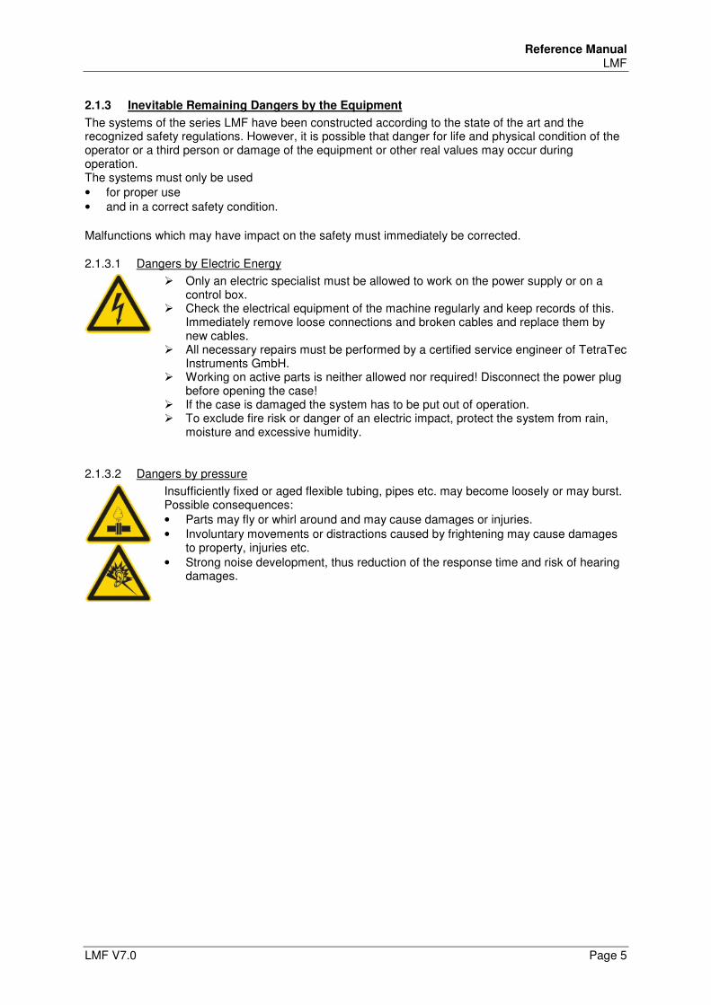
2.1.3.1 Dangers by Electric Energy
Only an electric specialist must be allowed to work on the power supply or on a control box.
Check the electrical equipment of the machine regularly and keep records of this. Immediately remove loose connections and broken cables and replace them by new cables.
All necessary repairs must be performed by a certified service engineer of TetraTec Instruments GmbH.
Working on active parts is neither allowed nor required! Disconnect the power plug before opening the case!
If the case is damaged the system has to be put out of operation. To exclude fire risk or danger of an electric impact, protect the system from rain,
moisture and excessive humidity.
2.1.3.2 Dangers by pressure
Insufficiently fixed or aged flexible tubing, pipes etc. may become loosely or may burst. Possible consequences: • Parts may fly or whirl around and may cause damages or injuries. • Involuntary movements or distractions caused by frightening may cause damages
to property, injuries etc. • Strong noise development, thus reduction of the response time and risk of hearing
damages.
Reference Manual LMF
Page 6 LMF V7.0
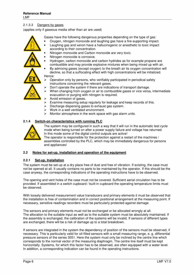
2.1.3.3 Dangers by gases
(applies only if gaseous media other than air are used)
Gases have the following dangerous properties depending on the type of gas: • Oxygen, nitrogen monoxide and laughing gas have a fire-supporting impact. • Laughing gas and xenon have a hallucinogenic or anesthetic to toxic impact
according to their concentration. • Nitrogen monoxide and Carbon monoxide are very toxic. • Nitrogen monoxide is corrosive. • Hydrogen, carbon monoxide and carbon hydrides as for example propane are
combustible and may provide explosive mixtures when being mixed up with air. • By admixing gases (except oxygen) to the breath air its oxygen concentration will
decline, so that a suffocating effect with high concentrations will be initialized. Hence: Operation only by persons, who verifiably participated in periodical safety
instructions concerning the relevant gases. Don’t operate the system if there are indications of transport damage. When changing from oxygen or air to combustible gases or vice versa, intermediate
evacuation or purging with nitrogen is required. Avoid emission of gases. Examine measuring setup regularly for leakage and keep records of this. Discharge dispersing gases to exhaust gas system. Work in a well ventilated environment. Monitor atmosphere in the work space with gas alarm units.
2.1.4 Switch-on characteristics with running PLC
The system may be configured in such a way that it will run in the automatic test cycle mode when being turned on after a power supply failure and voltage has returned. In this mode some of the digital control outputs are active! The operator is responsible for the protection against a restart of the machines / assemblies controlled by the PLC, which may be immediately dangerous for persons and appliances!
2.2 Notes for set-up, installation and operation of the equipment
2.2.1 Set-up, Installation
The system must be set-up at a dry place free of dust and free of vibration. If existing, the case must not be opened at all. It usually contains no parts to be maintained by the operator. If this should be the case anyway, the corresponding indications of the operating instructions have to be observed. The opening and vent holes of the case must not be covered. Sufficient aerial circulation has to be provided. If assembled in a switch cupboard / built-in cupboard the operating temperature limits must be observed. With loosely delivered measurement value transducers and primary elements it must be observed that the installation is free of contamination and in correct positional arrangement at the measuring point. If necessary, sensitive readings recorders must be particularly protected against damage. The sensors and primary elements must not be exchanged or be allocated wrongly at all. The allocation to the suitable input as well as to the suitable system must be absolutely maintained. If the assembly is exchanged, the calibration of the systems will be invalid. If sensors of different types are exchanged, there will be a risk of damage up to a total breakdown. If sensors are integrated in the system the dependency of position of the sensors must be observed, if necessary. This is particularly valid for oil-filled sensors with a small measuring range, e. g. differential pressure sensors of the series 3051. Here the system must only be inclined by the centre line which corresponds to the normal vector of the measuring diaphragm. The centre line itself must be kept horizontally. Systems, for which this factor has to be observed, are often equipped with a water level. In addition, a corresponding indication can be found in the operating instructions.
Reference Manual LMF
LMF V7.0 Page 7
2.2.2 Operating Conditions, Ambient Conditions
Operating temperature: 5°C up to 40°C. With special applications differing temperature limits may be valid for external test section designs. Ambient pressure atmospheric pressure working pressure: See application-specific operating instructions. humidity range: 0 ... 90% of relative humidity, not condensing! Before the system is turned on it must be adapted to the room temperature, the system must not be with dew at all.
2.2.3 Power supply, electric connection of systems with mains connection
2.2.3.1 OEM-system or Controller S320 delivered as a component
Controller S320 is supplied with 24 V. The 0V connection has to be connected with the protective earth conductor.
2.2.3.2 Systems with uniphase mains supply
110 - 230 VAC (50/60 Hz) Only the provided power cords or power cords with equivalent test sign must be used. The power supply must comply with the currently valid specifications.
2.2.3.3 Systems with protective case
110 - 230 VAC (50/60 Hz) The connector assembly set must only be installed by a qualified electrician.
2.2.3.4 Systems with control box
Monophase and multiphase systems with control box must only be installed by a qualified electrician.
2.2.4 Cleaning of the system
Wipe with a moist but not watery cloth.
Note Near open pressure-measuring lines, silencers or sensor inputs should not be cleaned with compressed air, because of sensitive sensors can be damaged!
2.2.5 Calibration, measuring accuracy
The systems are delivered by TetraTec Instruments being calibrated and readily configured. Any change of the calibration coefficient or other scaling factors and constants used internally may make the calibration invalid or reduce the measuring accuracy.
Reference Manual LMF
Page 8 LMF V7.0
2.2.6 Structural changes on systems and measuring sections
All measures of conversion require tests and written approval by TetraTec Instruments. No changes, attachments or conversions of the system or measuring section must be carried out
without approval of the manufacturer. Only use original spare parts and wearing parts.
With parts supplied by third companies there is no guarantee of being constructed and manufactured appropriately for stress and safety or that they meet metrological requirements.
• The exchange of sensors and measuring sections must be coordinated with TetraTec Instruments GmbH, because possibly a new measurement may be necessary.
• Only sensors and measuring sections supplied and calibrated by TetraTec Instruments must be used.
2.2.7 Limit parameter access
It is possible to limit the parameter access in the editing mode. The first paragraph of this chapter explains, according to which scheme the parameters are allocated to access levels defined by the factory. In the second paragraph there is information about the definition of own user groups and a documentation of the user groups preset by the factory and their passwords. Note: The operator or his system administrator is responsible for the changing of at least the passwords, keeping records of them and to keep this documentation at a save place. Further information
• For the consequences of the restrictions of access in the editing mode see chapter 7.4.3.2 • Access restriction for TCP connection see chapter5.2.6
2.2.7.1 Level allocation of the parameters
On site each parameter is allocated to a lot of level. This is carried out by the attribute "level=n". Here "n" is a number the single bits of which encode the respective level.
Examples
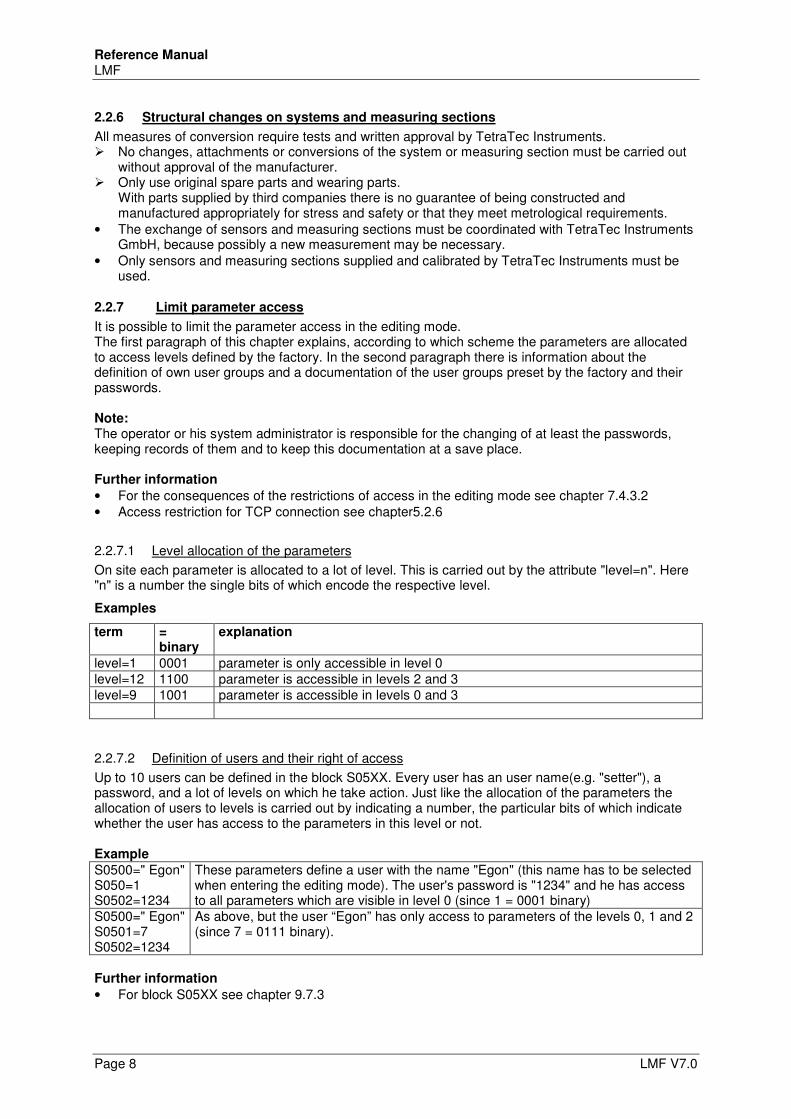
term = binary
explanation
level=1 0001 parameter is only accessible in level 0 level=12 1100 parameter is accessible in levels 2 and 3 level=9 1001 parameter is accessible in levels 0 and 3
2.2.7.2 Definition of users and their right of access
Up to 10 users can be defined in the block S05XX. Every user has an user name(e.g. "setter"), a password, and a lot of levels on which he take action. Just like the allocation of the parameters the allocation of users to levels is carried out by indicating a number, the particular bits of which indicate whether the user has access to the parameters in this level or not. Example
S0500=" Egon" S050=1 S0502=1234
These parameters define a user with the name "Egon" (this name has to be selected when entering the editing mode). The user's password is "1234" and he has access to all parameters which are visible in level 0 (since 1 = 0001 binary)
S0500=" Egon" S0501=7 S0502=1234
As above, but the user “Egon” has only access to parameters of the levels 0, 1 and 2 (since 7 = 0111 binary).
Further information
• For block S05XX see chapter 9.7.3
Reference Manual LMF
LMF V7.0 Page 9
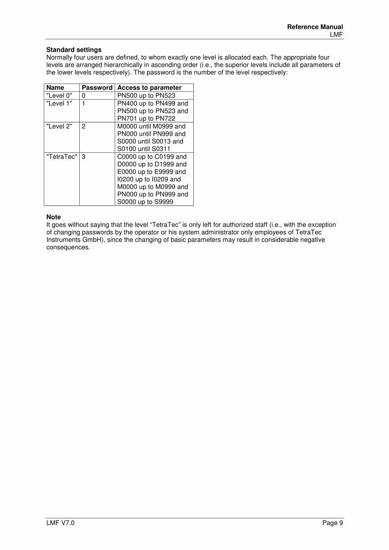
Standard settings Normally four users are defined, to whom exactly one level is allocated each. The appropriate four levels are arranged hierarchically in ascending order (i.e., the superior levels include all parameters of the lower levels respectively). The password is the number of the level respectively: Name Password Access to parameter
"Level 0" 0 PN500 up to PN523 "Level 1" 1 PN400 up to PN499 and
PN500 up to PN523 and PN701 up to PN722
"Level 2" 2 M0000 until M0999 and PN000 until PN999 and S0000 until S0013 and S0100 until S0311
"TetraTec" 3 C0000 up to C0199 and D0000 up to D1999 and E0000 up to E9999 and I0200 up to I0209 and M0000 up to M0999 and PN000 up to PN999 and S0000 up to S9999
Note It goes without saying that the level “TetraTec” is only left for authorized staff (i.e., with the exception of changing passwords by the operator or his system administrator only employees of TetraTec Instruments GmbH), since the changing of basic parameters may result in considerable negative consequences.
Reference Manual LMF
Page 10 LMF V7.0
3 Components of a LMF System
3.1 Overview
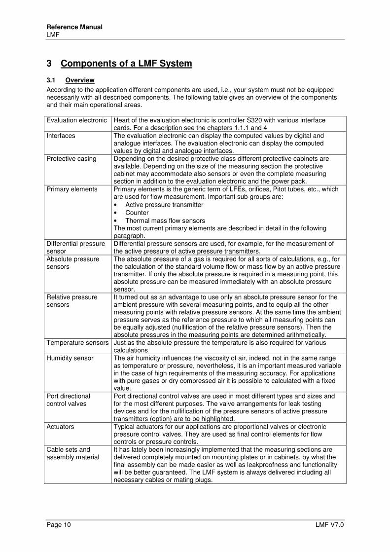
According to the application different components are used, i.e., your system must not be equipped necessarily with all described components. The following table gives an overview of the components and their main operational areas. Evaluation electronic Heart of the evaluation electronic is controller S320 with various interface
cards. For a description see the chapters 1.1.1 and 4 Interfaces The evaluation electronic can display the computed values by digital and
analogue interfaces. The evaluation electronic can display the computed values by digital and analogue interfaces.
Protective casing Depending on the desired protective class different protective cabinets are available. Depending on the size of the measuring section the protective cabinet may accommodate also sensors or even the complete measuring section in addition to the evaluation electronic and the power pack.
Primary elements Primary elements is the generic term of LFEs, orifices, Pitot tubes, etc., which are used for flow measurement. Important sub-groups are: • Active pressure transmitter • Counter • Thermal mass flow sensors The most current primary elements are described in detail in the following paragraph.
Differential pressure sensor
Differential pressure sensors are used, for example, for the measurement of the active pressure of active pressure transmitters.
Absolute pressure sensors
The absolute pressure of a gas is required for all sorts of calculations, e.g., for the calculation of the standard volume flow or mass flow by an active pressure transmitter. If only the absolute pressure is required in a measuring point, this absolute pressure can be measured immediately with an absolute pressure sensor.
Relative pressure sensors
It turned out as an advantage to use only an absolute pressure sensor for the ambient pressure with several measuring points, and to equip all the other measuring points with relative pressure sensors. At the same time the ambient pressure serves as the reference pressure to which all measuring points can be equally adjusted (nullification of the relative pressure sensors). Then the absolute pressures in the measuring points are determined arithmetically.
Temperature sensors Just as the absolute pressure the temperature is also required for various calculations
Humidity sensor The air humidity influences the viscosity of air, indeed, not in the same range as temperature or pressure, nevertheless, it is an important measured variable in the case of high requirements of the measuring accuracy. For applications with pure gases or dry compressed air it is possible to calculated with a fixed value.
Port directional control valves
Port directional control valves are used in most different types and sizes and for the most different purposes. The valve arrangements for leak testing devices and for the nullification of the pressure sensors of active pressure transmitters (option) are to be highlighted.
Actuators Typical actuators for our applications are proportional valves or electronic pressure control valves. They are used as final control elements for flow controls or pressure controls.
Cable sets and assembly material
It has lately been increasingly implemented that the measuring sections are delivered completely mounted on mounting plates or in cabinets, by what the final assembly can be made easier as well as leakproofness and functionality will be better guaranteed. The LMF system is always delivered including all necessary cables or mating plugs.
Reference Manual LMF
LMF V7.0 Page 11
3.2 Primary elements
The primary element most often used by us is the LFE, since among other things its linear behaviour allows a high accuracy over a wide span. Other primary elements like orifices, accutubes, critical nozzles, gas meters or mass flow meters have other advantages according to the measuring problem, which shall be briefly characterized here.
3.2.1 Active pressure transmitter
3.2.1.1 LFE
Mode of operation The volumetric flow rate through the LFE generates a laminar flow in the capillaries or gaps of the LFE. The pressure drop of the laminar flow section is proportional to the product of the current volume flow and the current viscosity. Accuracy With LFE as a primary element the LMF system works with a typical measuring accuracy of 0.5 to 1% or better, referred to the measurement value of the current volume flow in the measuring range of 1:10 (1:50 optionally). This accuracy is also reached with variable line pressure or variable temperature, provided that the sensors for temperature and absolute pressure are integrated. The system is applicable with slightly diminished accuracy with a span of up to 1:20 (1:100 optionally). For the improvement of the measuring accuracy system-related non-linearities of the LFE as well as of the sensors are compensated arithmetically. Operating conditions Since the capillaries of the LFE are easily choked by condensates or particles, LFEs can only be operated reasonably with well filtered gases (or air). In addition, there may be a temperature restriction by the used materials. E.g., the LFEs of the series 50MK10 are limited to 70°C, since the capillaries are poured in with epoxy resin. LFEs, which do not intake atmospherically, are operated in closed line systems.
3.2.1.2 Orifices, subcritically operated nozzles
Mode of operation A constriction causes an acceleration of the flowing medium and results in a pressure drop which can be measured between face and back as differential pressure (active pressure). The active pressure behaves proportionally to the square of the flow or vice versa: The flow is proportional for the square root of the measured active pressure. The pressure drop is remaining as a result of the turbulences. Accuracy As a result of the very non-linear characteristic curve a good accuracy can only be guaranteed by a very limited span. Operating conditions With adequate opening diameter relatively insensitive against fouling. All components consisting of highly heatable material can also be manufactured by this simple setup. Another advantage is the small installation length, especially with the orifices. Here an easy replacement is often possible. Orifices and nozzles are operated in closed line systems.
3.2.1.3 Venturi tubes
For mode of operation, accuracy and conditions of use the same is valid in principle as with orifices, however, the active pressure is measured between the inlet and the narrowest point of the Venturi tube. The soft cross-sectional extension following the constriction has the effect that a part of the flow energy is transformed to pressure energy, whereby the remaining pressure drop is clearly less than the active pressure. A disadvantage is the clearly bigger installation length and the higher costs according to the type of the toroid and conical segments.
Reference Manual LMF
Page 12 LMF V7.0
3.2.1.4 Pitot tubes, Pitot crosses and similar ones
For mode of operation and accuracy the same is valid as with orifices, in principle, only that the acceleration is not caused by a constriction but by the displacement of the probes. The operational area differs basically in the fact that the use is not bound to lines, i.e., it is possible outside in principle (e.g., as a speedometer aboard an airplane).
3.2.2 Counter
Counters are incremental or frequency transmitters. A common feature of all counters is, that there is no valid measurement value as long as no least number of pulses has been entered. Hence, it cannot be avoided that at the beginning of the measurement no measurement result can be displayed and that any measurement result is a gliding and delayed average.
3.2.2.1 Turbine wheel gas meter, impeller gas meter
Mode of operation A turbine wheel is rotationally moved by the flow. The rotating speed soon reaches a balance with the flow speed. The rotations are counted.
3.2.2.2 Drum gas meter, rotary piston gas meter, bellows gas meter, experimental gas meter
The counters of the enumerated models measure the flowing volume. The medium fills one or several measuring chambers alternately and thus drives a speedometer. As a rule the speedometer supplies only one pulse per each rotation, however, there are also types with a finer resolution.
3.2.3 Miscellaneous
3.2.3.1 Mass flow meters
Mass flow meters measure the transmission of heat which is performed by the flowing media. In addition, a defined surface (or also a wire) is kept on constant temperature in the middle of the pipe. The required electric power is a measure for the transmission of heat and thus for the mass flow. An advantage is the small pressure loss with high accuracy and small installation length. The main disadvantage is the slowness, since a measurement is only valid in the thermal balance.
3.2.3.2 Overcritical nozzles
The flow of overcritical nozzles in the constriction is limited by the speed of sound. Hence, an overcritical nozzle can be used very well for generating a certain flow which basically depends on the geometry of the nozzle, the speed of sound (depending on temperature) and the density (depending on pressure) before the entry into the nozzle. Typical applications are test leaks and regulation tasks. Nozzles can be put together to nozzle galleries in combination with valves. Therefore different flows can be switched by the combination of different nozzles.
Reference Manual LMF
LMF V7.0 Page 13
4 Operational controls
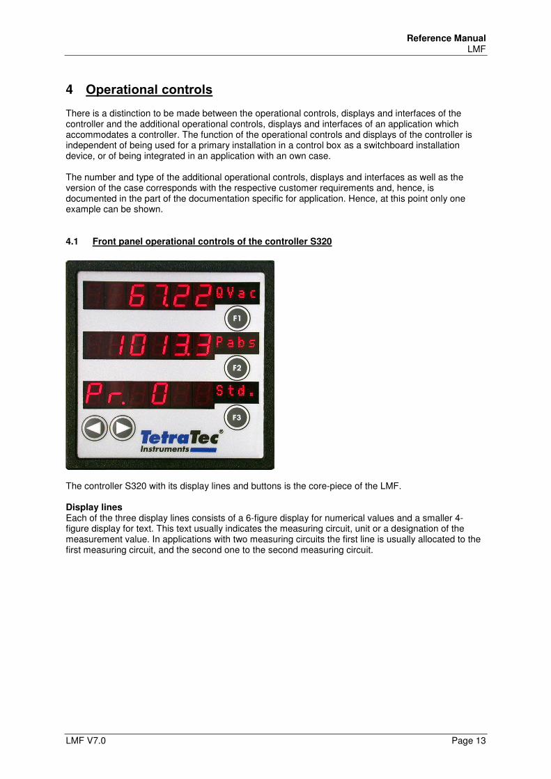
There is a distinction to be made between the operational controls, displays and interfaces of the controller and the additional operational controls, displays and interfaces of an application which accommodates a controller. The function of the operational controls and displays of the controller is independent of being used for a primary installation in a control box as a switchboard installation device, or of being integrated in an application with an own case. The number and type of the additional operational controls, displays and interfaces as well as the version of the case corresponds with the respective customer requirements and, hence, is documented in the part of the documentation specific for application. Hence, at this point only one example can be shown.
4.1 Front panel operational controls of the controller S320
The controller S320 with its display lines and buttons is the core-piece of the LMF. Display lines Each of the three display lines consists of a 6-figure display for numerical values and a smaller 4-figure display for text. This text usually indicates the measuring circuit, unit or a designation of the measurement value. In applications with two measuring circuits the first line is usually allocated to the first measuring circuit, and the second one to the second measuring circuit.
Reference Manual LMF
Page 14 LMF V7.0
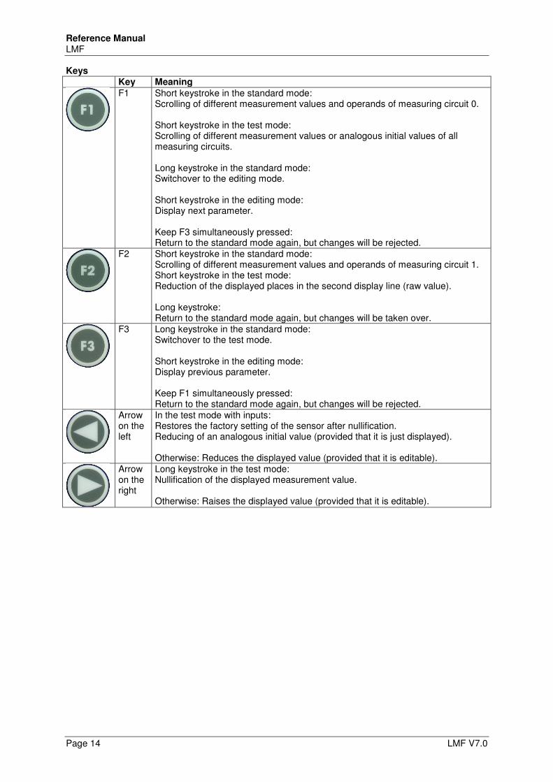
Keys
Key Meaning
F1 Short keystroke in the standard mode: Scrolling of different measurement values and operands of measuring circuit 0. Short keystroke in the test mode: Scrolling of different measurement values or analogous initial values of all measuring circuits. Long keystroke in the standard mode: Switchover to the editing mode. Short keystroke in the editing mode: Display next parameter. Keep F3 simultaneously pressed: Return to the standard mode again, but changes will be rejected.
F2 Short keystroke in the standard mode: Scrolling of different measurement values and operands of measuring circuit 1. Short keystroke in the test mode: Reduction of the displayed places in the second display line (raw value). Long keystroke: Return to the standard mode again, but changes will be taken over.
F3 Long keystroke in the standard mode: Switchover to the test mode. Short keystroke in the editing mode: Display previous parameter. Keep F1 simultaneously pressed: Return to the standard mode again, but changes will be rejected.
Arrow on the left
In the test mode with inputs: Restores the factory setting of the sensor after nullification. Reducing of an analogous initial value (provided that it is just displayed). Otherwise: Reduces the displayed value (provided that it is editable).
Arrow on the right
Long keystroke in the test mode: Nullification of the displayed measurement value. Otherwise: Raises the displayed value (provided that it is editable).
Reference Manual LMF
LMF V7.0 Page 15
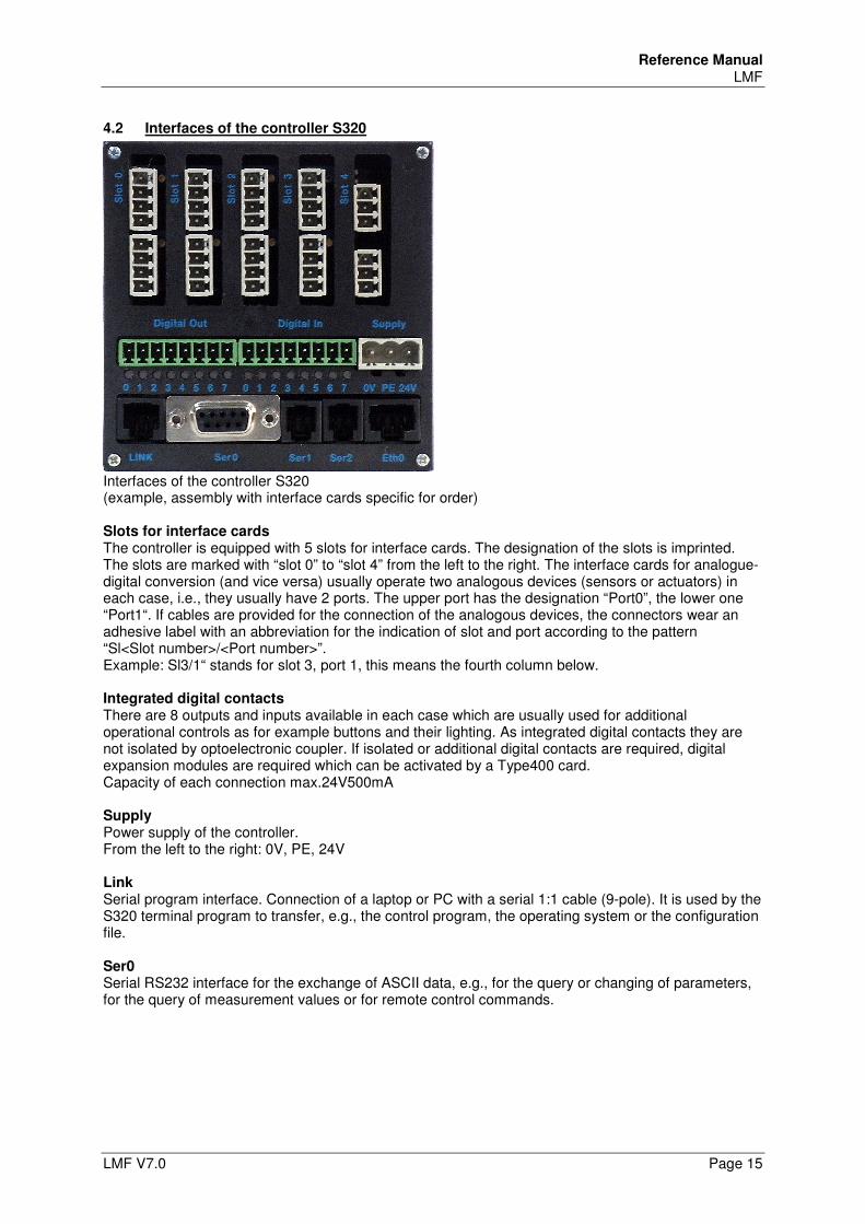
4.2 Interfaces of the controller S320
Interfaces of the controller S320 (example, assembly with interface cards specific for order) Slots for interface cards The controller is equipped with 5 slots for interface cards. The designation of the slots is imprinted. The slots are marked with “slot 0” to “slot 4” from the left to the right. The interface cards for analogue-digital conversion (and vice versa) usually operate two analogous devices (sensors or actuators) in each case, i.e., they usually have 2 ports. The upper port has the designation “Port0”, the lower one “Port1“. If cables are provided for the connection of the analogous devices, the connectors wear an adhesive label with an abbreviation for the indication of slot and port according to the pattern “Sl<Slot number>/<Port number>”. Example: Sl3/1“ stands for slot 3, port 1, this means the fourth column below. Integrated digital contacts There are 8 outputs and inputs available in each case which are usually used for additional operational controls as for example buttons and their lighting. As integrated digital contacts they are not isolated by optoelectronic coupler. If isolated or additional digital contacts are required, digital expansion modules are required which can be activated by a Type400 card. Capacity of each connection max.24V500mA Supply Power supply of the controller. From the left to the right: 0V, PE, 24V Link Serial program interface. Connection of a laptop or PC with a serial 1:1 cable (9-pole). It is used by the S320 terminal program to transfer, e.g., the control program, the operating system or the configuration file. Ser0 Serial RS232 interface for the exchange of ASCII data, e.g., for the query or changing of parameters, for the query of measurement values or for remote control commands.
Reference Manual LMF
Page 16 LMF V7.0
Ser1 Serial RS485 interfaces, is normally used for the interlinking of several controllers. Ser2 Serial RS485 interfaces, is usually used for the connection of serial sensors. Eth0 Ethernet interface(TCP/IP).
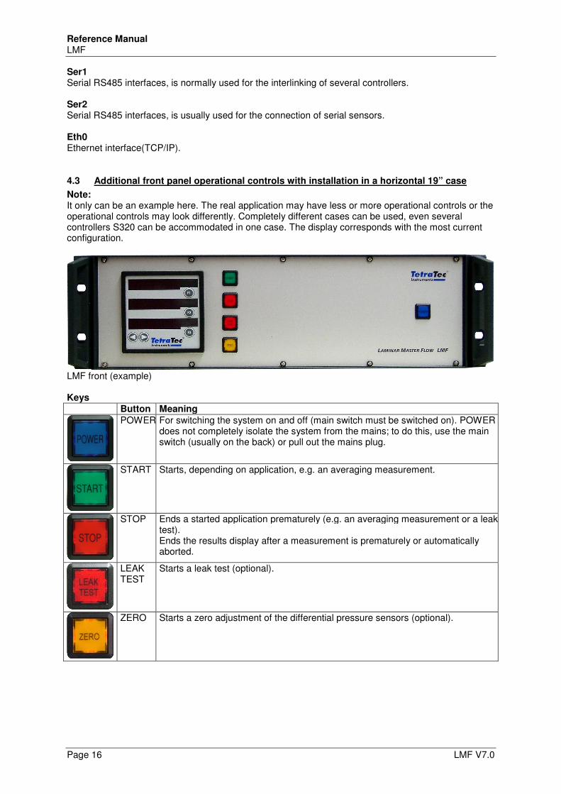
4.3 Additional front panel operational controls with installation in a horizontal 19” case
Note: It only can be an example here. The real application may have less or more operational controls or the operational controls may look differently. Completely different cases can be used, even several controllers S320 can be accommodated in one case. The display corresponds with the most current configuration.
LMF front (example) Keys
Button Meaning
POWER For switching the system on and off (main switch must be switched on). POWER does not completely isolate the system from the mains; to do this, use the main switch (usually on the back) or pull out the mains plug.
START Starts, depending on application, e.g. an averaging measurement.
STOP Ends a started application prematurely (e.g. an averaging measurement or a leak test). Ends the results display after a measurement is prematurely or automatically aborted.
LEAK TEST
Starts a leak test (optional).
ZERO Starts a zero adjustment of the differential pressure sensors (optional).
Reference Manual LMF
LMF V7.0 Page 17
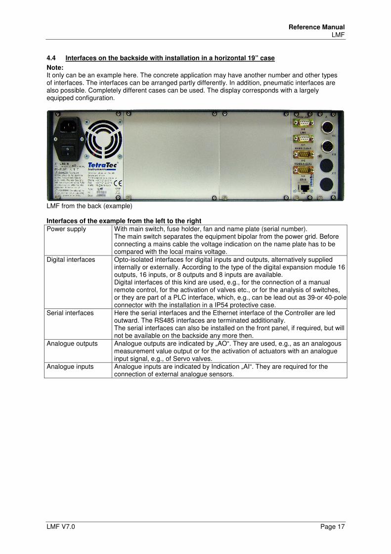
4.4 Interfaces on the backside with installation in a horizontal 19” case
Note: It only can be an example here. The concrete application may have another number and other types of interfaces. The interfaces can be arranged partly differently. In addition, pneumatic interfaces are also possible. Completely different cases can be used. The display corresponds with a largely equipped configuration.
LMF from the back (example) Interfaces of the example from the left to the right
Power supply With main switch, fuse holder, fan and name plate (serial number). The main switch separates the equipment bipolar from the power grid. Before connecting a mains cable the voltage indication on the name plate has to be compared with the local mains voltage.
Digital interfaces Opto-isolated interfaces for digital inputs and outputs, alternatively supplied internally or externally. According to the type of the digital expansion module 16 outputs, 16 inputs, or 8 outputs and 8 inputs are available. Digital interfaces of this kind are used, e.g., for the connection of a manual remote control, for the activation of valves etc., or for the analysis of switches, or they are part of a PLC interface, which, e.g., can be lead out as 39-or 40-pole connector with the installation in a IP54 protective case.
Serial interfaces Here the serial interfaces and the Ethernet interface of the Controller are led outward. The RS485 interfaces are terminated additionally. The serial interfaces can also be installed on the front panel, if required, but will not be available on the backside any more then.
Analogue outputs Analogue outputs are indicated by „AO“. They are used, e.g., as an analogous measurement value output or for the activation of actuators with an analogue input signal, e.g., of Servo valves.
Analogue inputs Analogue inputs are indicated by Indication „AI“. They are required for the connection of external analogue sensors.
Reference Manual LMF
Page 18 LMF V7.0
5 Interfaces for Remote Control
For communication with terminal programs, the controller S320 contained in the LMF uses two logical interfaces: • „Link“ • „Comm“ • „AK protocol“ (optional) The interface “Link” supports the additional functions of the terminal program S320 provided on the CD for programming and installation, e.g. a graphic real time display of measurement values. A complete remote control is possible by the interface “Comm”. It is possible to query and change parameters, query information, or trigger operations. The command HELP displays an overview of the available commands. In addition each standard terminal program(ASCII mode) can be used, for example the terminal program Telnet included in the scope of delivery of Microsoft Windows. The software S320 contained on the included CD also provides such a terminal. The interface „AK protocol“ is an interface for remote control of cycles in master/slave operation, thus can be compared with a PLC interface. It is activated on special customer request and it is configured custom-designed. For general information about the „AK protocol“ see in section 5.6, for custom-designed additional information see in the Short Manual in chapter „Options“, if necessary. It is possible to establish a connection physically to all interfaces by the Ethernet connection (TCP/IP) or by both RS232 connections (with restrictions). Normally the RS232 connection for the interface “Comm” is indicated with “RS232/Ser0”. If the Ethernet connection is used, all interfaces will be identified by the IP address of the controller and different port numbers. If a high data rate is required, (e. g. graphic real time display of numerous measurement values), the use of the Ethernet connection is recommended. Example telnet <IP address or name> <port number> The IP address can be set by the interface „Link“ by using the appropriate RS232 connection for this purpose. The port numbers of the COMM interface and of the AK interface are determined by the parameters S0020 and S9600. Notes:
• The RS485 connections are designed for the connection of serial sensors. Since by now there are better possibilities available for the cross linking of several controllers, the use of the RS485 connections is not supported any more for this purpose.
• If one of the two RS485 interfaces is required for internal serial sensors, the case connector usually provided for this interface is not allocated.
• For special cases only the required active connections are led through possibly.
Reference Manual LMF
LMF V7.0 Page 19
5.1 Set up RS232 interface
\The serial interface is preset, the settings can be seen in the configuration file. However, the settings are also accessible as a parameter, i.e., they may be changed with the front panel operational controls or with an existing serial connection.
5.1.1 Default settings in the configuration file:
Baud rate: The transmission rate of the RS 232 interface Standard setting: 9600 baud. Parity: Setting of the parity bit. Standard setting: NONE (no parity bit) Stop bits: Number of stop bits of the RS 232 transmitter Standard setting: 1 stop bit (the receiver is always set to 1 stop bit), Handshake: Setting of the handshake process: Standard setting: none neither RTS/CTS (only hardware handshake) nor XON/XOFF (software handshake) Other settings are possible, if requested. The settings are saved in the parameters S0006 to S0009, see chapter 9.7.1
5.1.2 Interface settings in the terminal program
If the terminal program S320 is used, the entries will be saved, so it is not necessary to care about it afterwards. Open the menu “Connect” and click on “Comm Settings“.
The window “Global Settings” appears with the opened tab “Comm“. Enter the interface you are using, e.g., “com1”, in the left field If you also want to use the link connection, please repeat the settings in the tab “Link“. Note If you want to use both interfaces at the same time, you will need a second Comm interface or an USB serial adapter. In this case you must enter this other serial interface of your computer in the tab “Link”. However, if you only have one interface or only one cable, you can use the interfaces alternately only. Enter this interface in both tabs then. Close the window “Global Settings” with “OK“.
5.1.3 Test function of the serial interface
You will need a serial 1:1 cable with control wire with a 9-pole D Sub jack and a 9-pole D Sub connector (included in delivery).
Connect the serial interface of the LMF with the serial interface of your computer. If you use a general terminal program, provide a connection with the serial interface of your
computer. - or - If terminal program S320 is used, switchover to tab “CommMsg” and click on the button “Connect
Comm” in the launch-pad. Press the enter key of your computer.
The connection works properly if you receive the response “Press help for details”.
Reference Manual LMF
Page 20 LMF V7.0
5.1.4 Test function of the link interface
You need a computer with the installed terminal program S320 If an OEM controller shall be connected directly: a provided link cable - or - If you want to connect a LMF with protective case: A serial 1:1 cable with control wire with a 9-pole
D Sub jack and a 9-pole D Sub connector is required (included in delivery). Connect the link interface of the LMF with the serial interface of your computer. Click on “Connect Link” in the launchpad of the terminal program S320.
The connection works properly if the successful setup of the link connection is displayed in the footer of the terminal program.
5.2 Set up network interface
Tip: You will find detailed instructions with pictures in the document "S320_Short_Instructions.pdf", which is just like the S320 terminal software on the supplied CD. You need a computer with the installed terminal program S320 a working link connection a released IP address
5.2.1 Change the IP address of the LMF
Tip: Consult your network administrator for the assignment of the IP address. If a DNS server is available, your network administrator can also assign a memorable computer name to the address what makes the access more comfortable later. To open the input mask for the IP address, click on the entry “Network Configuration” in the menu
“System“. Make sure that the option “Network enabled” is active. So far required, overwrite the Default IP address and customize the net mask, if necessary.
5.2.2 Port Number of Link-Interface
The port number of the Link-Interface is fixed to 54490.
5.2.3 Port Number of Comm-Interface
As a rule the port number of the Comm-interface is set to 54491. It can be set different custom-designed, but this special setting will be documented in the project specific paperwork. To read out the port number of the Comm-interface query parameter S0020. It is recommended not to change it.
5.2.4 Usage of IP address and port number in the terminal program
The terminal program must know the IP address (or, instead, the name of the computer of the LMF) and the port number. With Telnet these entries are attached simply behind with the program request by command. If the terminal program S320 is used, the entries will be saved, so it is not necessary to care about it afterwards. Open the menu “Connect” and click on “Comm Settings“.
The window “Global Settings” appears with the opened tab “Comm“. Enter the IP address or the computer name of the LMF and the port number in the right field. If you also want to use the link connection, please repeat the settings in the tab “Link“. Close the window “Global Settings” with “OK“.
Reference Manual LMF
LMF V7.0 Page 21
5.2.5 Test connection
If a general terminal program is used, provide a connection with IP address and port number. - or - If terminal program S320 is used, switchover to tab “CommMsg” and click on the button “Connect
Comm” in the launchpad. Press the enter key of your computer.
The connection works properly if you receive the response “Press help for details”.
5.2.6 Access restrictions
When using a network there are clearly more computers existing from which an access is possible compared to the access of other interfaces (e.g., RS232). Normally physical access to the system is not necessary any more. Even access by Internet is possible, for example. To limit the number of computers, from which an access is possible, two string parameters with access lists exist for each network connection. These two string parameters are indicated as “Allow” and “Deny” for the following explanation. Each of these parameters contains an access list for the particular connection, e.g., S0021 Allow
for COMM connection with TCP S0022 Deny S9308 Allow
for protocol printout, if S9300=8 (passive output with TCP) S9309 Deny S9501 Allow
for virtual inputs and outputs S9502 Deny Basic principles of the TCP/IP network protocol are necessary for the understanding of the access lists. The following is valid, in principle: Only accesses of IP numbers or computer names can be configured. An access is allowed if and only if the Allow list allows access or if the Deny list does not forbid it. If both lists are used, the Allow list has higher priority. Each of both string parameters may contain a list of IP numbers, or computer names as a substitute. The use of computer names only works properly if a valid DNS server is entered in the network configuration of the controller, which is able to break down the used computer names. In addition, for each specification the entry of a net mask is still possible. Several computers are separated by semicolons, the (optional) net mask is separated by a slash. A preceding exclamation mark negates the comparison. Examples for the syntax of the access lists: # A computer specified by its IP number
192.168.28.13
# Other representation with explicit net mask
192.168.28.13/32
# A computer specified by its name
frodo.example.org
# An entire Class C network
192.168.28.0/24
# All computers with exception of a Class of C network
!192.168.28.0/24
# Two computers
192.168.28.13;192.168.28.55
# Two computers and a Class C network
192.168.28.13;frodo.example.org;192.168.0.0/24
Reference Manual LMF
Page 22 LMF V7.0
Examples for the use of the access lists To allow access with the Comm interface for exactly one computer, this computer will be included in the suitable Allow list. The corresponding Deny list must include all the other computers: S0021=192.168.28.13 #Allow list for COMM connection
S0022=0.0.0.0/0 #Deny list for COMM connection
An alternative configuration is possible with the help of the negation operator: S0021=”” # Allow list is empty
S0022=!192.168.28.13 # Deny list contains all except one computer
Access for a local network, as well as for another computer: S0021=192.168.28.0/24;myhost.lan # Allow list
S0022=0.0.0.0/0 # Deny list
Access for all computers with the exception of computer public.example.org: S0021=”” # Allow list is empty
S0022=public.example.org # Deny list
The examples are also applicable for the other type of connections mentioned above.
5.3 Query and change of parameters
Note While the LMF is in the editing mode, no values can be changed by the „Comm“ interface. If values have been changed by the „Comm“ interface, which still have not been acknowledged by “EXIT” or “SAVE”, these values cannot be changed in the editing mode using the keyboard.
5.3.1 Physical units
Many of the parameters represent physical values. If, in addition, there are several units (e.g., PSI and mbar as a unit for pressure), the unit can be selected in the editing mode. However, this does not apply for a query or change by remote control. Here the indication of the units is abandoned. This is why the values are always applied in SI units. Hence, with the input of a parameter value the previous conversion to SI units has to be regarded. The input of physical units is not allowed.
5.3.2 Query parameters
Any parameter may be queried by simply entering its name. A list of parameters may be queried by replacing single digits in the name by the question mark. Example: p000?
Output of the controller: P0000=0
P0001=1
P0003=2
P0004=1
If parameters have been changed, but up to now none of the commands TEMP or SAVE have been used to make the parameters effective, then the currently valid value, followed by a ‚#’ sign, and the new value will be displayed.
Reference Manual LMF
LMF V7.0 Page 23
Example: p0000
Output of the controller: P0000=0 # 1
5.3.2.1 Query measurement values and arithmetic values
The measurement values and arithmetic values are saved in the R parameters. They can be queried as well as any other parameter. In addition, there is the option to use the command “RPAR” which makes available substantially more information. See also chapter 5.5.40. Note The R parameters belong to the parameters which cannot be changed.
5.3.3 Change parameters:
Most parameters can be changed by entering an equals sign and a value after the parameter name. Example: P0000=0
Output of the controller: P0000=0
For syntax of value indication see chapter 6.1 The allocated value must be within the valid limits of the respective parameter, otherwise “Range Error” will be returned. Some parameters are only readable (“Read-only”), trying to change them will result in the message “Access denied” then. Parameters which have been changed will not become effective immediately, but only if, in addition, one of the commands ACTIVATE, TEMP, or SAVE is entered. Error messages with the entering of values Bad data Appears if the value for the type of parameter is invalid. Example: A
number cannot be converted into the required number format. No match Appears if an input is recognized as a parameter, but this parameter does
not exist in the present configuration. Range error Appears if a value shall be allocated to a parameter which is below its
value range. No such command Appears if the input will not be recognized as a command.
Reference Manual LMF
Page 24 LMF V7.0
5.4 Virtual inputs and outputs
In addition to really existing digital inputs and outputs the application LMF also knows virtual ones which can be queried or set by a separate network interface.
The basic parameters for the connection are set in the parameter block S9500. The terms which determine the values of the virtual outputs are in parameter block S1300. Within control terms the value of a virtual input can be read with the function NI.
Further information
• Control terms see chapter 6.3 • Parameter block S1300 see chapter 9.7.7 • Parameter block S9500 see chapter 9.7.36
5.4.1 Communication
For communication with a remote station the system waits for an external starting of connection. Only one connection is possible at a time. The communication is carried out with readable (ASCII) strings, single lines are terminated with “Carriage Return” and “Line Feed”. The system understands the following messages:
QUIT
NI number
QUIT terminates the connection. With NI the system is informed of a change of the input signals. Each bit of the number indicated as a parameter corresponds to an input. The following number formats are allowed: • Decimal: [0-9]+ • Decimal: [0-9]+d • Hexadecimal: [0-9a-fA-F]+h • Binary; %[01]+ • Octal: &[0-7]+ • Hexadecimal: $[0-9a-fA-F]+
On the other hand, the controller also announces any change of the virtual outputs by this connection. The format in which the data are sent with a change of the outputs is configurable with parameter S9507. The definition of the format corresponds with the format used with the protocol pressure (S93XX), except that exactly one single integer argument is available, namely the current output state. The initial state is sent by the controller once immediately after the connection setup, so that the remote station knows it.
Further information
• Format strings see chapter 6.2
5.4.2 Timeouts
Connection errors (e.g. pulled network cable) may, for technical reasons, only be noticed if both systems exchange data. To make sure that such errors do not remain unnoticed, the configuration of timeouts is possible (and recommended).
If a reception timeout is configured, then the LMF assumes an error, if no command was received by the remote station for longer than the set time. The existing connection is cancelled and the system waits for a new connection. Caution: If a reception time-out is configured, the remote station must transmit data at regular intervals, otherwise the connection will be cancelled.
If a transmission timeout is configured, then the LMF itself sends data at least in configured intervals. Since the state of the outputs is ordinarily only transmitted if something has been changed, the current state is even then transmitted in the case of a transmission timeout if the time-out has run off.
A value of 0 for the respective timeout parameter switches off the timeout process.
5.4.3 Access control
Two other parameters permit the restriction of the access to the interface. See also chapter 5.2.6.
Reference Manual LMF
LMF V7.0 Page 25
5.5 List of the remote control commands of the Comm interface
Note The remote control commands will be valid no matter by which physical interface the logical Comm interface has been built up. If the RS485 interface has been used, the system address must precede the remote control commands.
5.5.1 ACTIVATE
ACTIVATE activates changed parameters like TEMP, but carries out no Soft-Reset. Particularly the currently running program is not switched, if one of the parameters relevant for that has been changed (e. g. S1000).
5.5.2 AKSEND
AKSEND sends an AK command, which is dealt with as if coming from the AK interface. This is also performed, when the port for the AK interface (S9600) is switched off. The command must not include a start or termination sign. The answer to the command is displayed.
5.5.3 CACHECTRL
CACHECTRL is for the control of the fast binary memory for the parameters. Entering the command without parameters results in an output of the current settings or of the state of the fast memory. The following optional parameters are valid: clear Clears the memory contents none Switches off the use of the memory base Uses the memory for the basis parameters (without changes by the user) full Uses the memory for all parameters (including changes by the user)
5.5.4 CONTROL
The command CONTROL displays the parameters for a controller. Two arguments are expected: The number of the program and the number of the controller in the program (0 or 1). Example: Control 0 0
----- Control #0/0 -----
P0400 - Mode : 1 (manual)
P0401 - Hot edit : FALSE
P0402 - T1 : +1.000000E-01
P0403 - TD : +0.000000E+00
P0404 - TI : +1.000000E+00
P0405 - VP : +1.000000E+00
P0406 - Cor lower limit: +0.000000E+00
P0407 - Cor upper limit: +1.000000E+00
P0411 - Actual Value : R0000
P0412 - ActV error mode: 0 (error)
P0416 - Reset behaviour: 0 (last value)
P0417 - Fixed reset val: +0.000000E+00
P0420 - SP scale enable: FALSE
P0421 - SP input : -1 (fixed value)
P0422 - Fixed SP : +0.000000E+00
P0425 - SP ramp : 0 (disabled)
P0430 - Lin method : 0 (none)
P0441 - SP disp unit : 1 (%)
P0442 - SP disp digits : 3
The parameter number precedes the output of the single parameters in each case. Inactive parameters are not displayed.
Reference Manual LMF
Page 26 LMF V7.0
5.5.5 DATE
The command DATE queries date and time of the controller, or sets them. Invoking without parameters returns the current values. Invoking with the entry of time and date as an argument sets the real time clock to the indicated value. The argument must have the format “dd.mm.yyyy hh:mm:ss”. The time will be saved fail-safe.
5.5.6 DEFAULTS
All parameters can be reset to the delivery state by the command DEFAULTS. The program requests for a second input for user settings not being deleted by mistake. This safety query can be switched off by parameter S0040. Example: defaults
Output of the controller: Please enter: "DEFAULTS 4c6a" within 15 seconds
Input: defaults 4c6a
Output of the controller: DEFAULTS: OK - will reboot in a moment
After having established the delivery state the system will be started again, so that changes become effective. With the first start the reset must be confirmed on the controller by pressing F1 additionally.
5.5.7 DIR
DIR displays the directory of the flash ROM.
5.5.8 DISCARD
DISCARD discards all parameter changes, which have not yet been taken over by TEMP or SAVE.
5.5.9 DLIST
The command DLIST displays a display list. A numerical argument (the number of the desired display list) is expected. Example: dlist 0
Output of the controller: --------- Display list 0 ---------
D0100 - Pages in list : 11
D0101 - Mode : 1 (row mode)
D0102 - Page #0 : 1
D0103 - Page #1 : 11
D0104 - Page #2 : 12
D0105 - Page #3 : 13
D0106 - Page #4 : 14
D0107 - Page #5 : 15
D0108 - Page #6 : 16
D0109 - Page #7 : 17
D0110 - Page #8 : 18
D0111 - Page #9 : 19
D0112 - Page #10 : 20
The parameter number precedes the output of the single parameters in each case. Inactive parameters are not displayed.
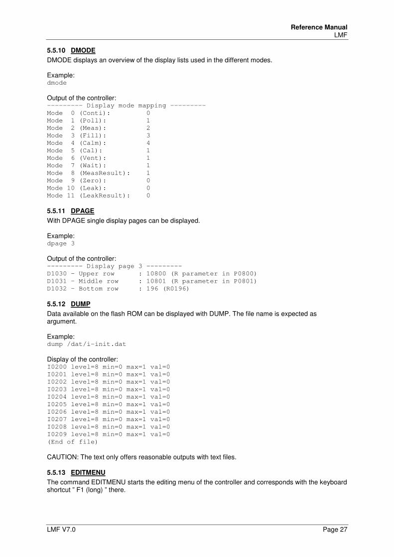
Reference Manual LMF
LMF V7.0 Page 27
5.5.10 DMODE
DMODE displays an overview of the display lists used in the different modes. Example: dmode
Output of the controller: --------- Display mode mapping ---------
Mode 0 (Conti): 0
Mode 1 (Poll): 1
Mode 2 (Meas): 2
Mode 3 (Fill): 3
Mode 4 (Calm): 4
Mode 5 (Cal): 1
Mode 6 (Vent): 1
Mode 7 (Wait): 1
Mode 8 (MeasResult): 1
Mode 9 (Zero): 0
Mode 10 (Leak): 0
Mode 11 (LeakResult): 0
5.5.11 DPAGE
With DPAGE single display pages can be displayed. Example: dpage 3
Output of the controller: --------- Display page 3 ---------
D1030 - Upper row : 10800 (R parameter in P0800)
D1031 - Middle row : 10801 (R parameter in P0801)
D1032 - Bottom row : 196 (R0196)
5.5.12 DUMP
Data available on the flash ROM can be displayed with DUMP. The file name is expected as argument. Example: dump /dat/i-init.dat
Display of the controller: I0200 level=8 min=0 max=1 val=0
I0201 level=8 min=0 max=1 val=0
I0202 level=8 min=0 max=1 val=0
I0203 level=8 min=0 max=1 val=0
I0204 level=8 min=0 max=1 val=0
I0205 level=8 min=0 max=1 val=0
I0206 level=8 min=0 max=1 val=0
I0207 level=8 min=0 max=1 val=0
I0208 level=8 min=0 max=1 val=0
I0209 level=8 min=0 max=1 val=0
(End of file)
CAUTION: The text only offers reasonable outputs with text files.
5.5.13 EDITMENU
The command EDITMENU starts the editing menu of the controller and corresponds with the keyboard shortcut ” F1 (long) ” there.
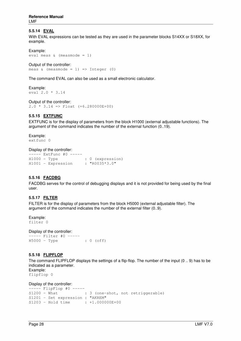
Reference Manual LMF
Page 28 LMF V7.0
5.5.14 EVAL
With EVAL expressions can be tested as they are used in the parameter blocks S14XX or S18XX, for example. Example: eval meas & (measmode = 1)
Output of the controller: meas & (measmode = 1) => Integer (0)
The command EVAL can also be used as a small electronic calculator. Example: eval 2.0 * 3.14
Output of the controller: 2.0 * 3.14 => Float (+6.280000E+00)
5.5.15 EXTFUNC
EXTFUNC is for the display of parameters from the block H1000 (external adjustable functions). The argument of the command indicates the number of the external function (0..19). Example: extfunc 0
Display of the controller: ----- ExtFunc #0 -----
H1000 - Type : 0 (expression)
H1001 - Expression : "R0035*3.0"
5.5.16 FACDBG
FACDBG serves for the control of debugging displays and it is not provided for being used by the final user.
5.5.17 FILTER
FILTER is for the display of parameters from the block H5000 (external adjustable filter). The argument of the command indicates the number of the external filter (0..9). Example: filter 0
Display of the controller: ----- Filter #0 -----
H5000 - Type : 0 (off)
5.5.18 FLIPFLOP
The command FLIPFLOP displays the settings of a flip-flop. The number of the input (0 .. 9) has to be indicated as a parameter. Example: flipflop 0
Display of the controller: ----- FlipFlop #0 -----
S1200 - What : 3 (one-shot, not retriggerable)
S1201 - Set expression : "AKREM"
S1203 - Hold time : +1.000000E+00
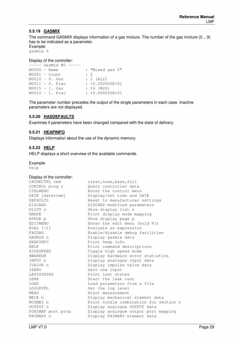
Reference Manual LMF
LMF V7.0 Page 29
5.5.19 GASMIX
The command GASMIX displays information of a gas mixture. The number of the gas mixture (0 .. 9) has to be indicated as a parameter. Example: gasmix 0
Display of the controller: ----- GasMix #0 -----
M0000 - Name : "Mixed gas 0"
M0001 - Count : 2
M0010 - 0. Gas : 1 (Air)
M0011 - 0. Frac : +5.000000E+01
M0015 - 1. Gas : 14 (N2O)
M0016 - 1. Frac : +5.000000E+01
The parameter number precedes the output of the single parameters in each case. Inactive parameters are not displayed.
5.5.20 HASDEFAULTS
Examines if parameters have been changed compared with the state of delivery.
5.5.21 HEAPINFO
Displays information about the use of the dynamic memory.
5.5.22 HELP
HELP displays a short overview of the available commands. Example: help
Display of the controller: CACHECTRL cmd clear,none,base,full
CONTROL prog c Query controller data
CTRLMENU Enter the control menu
DATE [datetime] Display/set time and DATE
DEFAULTS Reset to manufacturer settings
DISCARD DISCARD modified parameters
DLIST n Show display list n
DMODE Print display mode mapping
DPAGE p Show display page p
EDITMENU Enter the edit menu (hold F1)
EVAL [-t] Evaluate an expression
FACDBG Enable/disable debug facilities
GASMIX n Display gasmix data
HEAPINFO Print heap info
HELP Print command descriptions
HIGHSPEED Toggle high speed mode
HWERROR Display Hardware error statistics
INPUT n Display analogue input data
IVALVE n Display impulse valve data
IZERO Zero one input
LASTSTATES Print last states
LEAK Start the leak test
LOAD Load parameters from a file
LOGLEVEL Set the log level
MEAS Start measurement
MELE n Display mechanical element data
NCOMBI n Print nozzle combination for section n
OUTPUT n Display analogue OUTPUT data
PORTMAP port prog Display analogue output port mapping
PRIMARY n Display PRIMARY element data
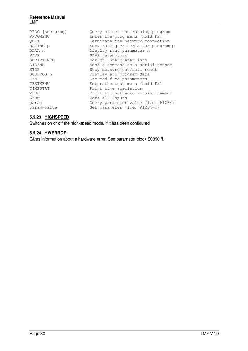
Reference Manual LMF
Page 30 LMF V7.0
PROG [sec prog] Query or set the running program
PROGMENU Enter the prog menu (hold F2)
QUIT Terminate the network connection
RATING p Show rating criteria for program p
RPAR n Display read parameter n
SAVE SAVE parameters
SCRIPTINFO Script interpreter info
SISEND Send a command to a serial sensor
STOP Stop measurement/soft reset
SUBPROG n Display sub program data
TEMP Use modified parameters
TESTMENU Enter the test menu (hold F3)
TIMESTAT Print time statistics
VERS Print the software version number
ZERO Zero all inputs
param Query parameter value (i.e. P1234)
param=value Set parameter (i.e. P1234=1)
5.5.23 HIGHSPEED
Switches on or off the high-speed mode, if it has been configured.
5.5.24 HWERROR
Gives information about a hardware error. See parameter block S0350 ff.
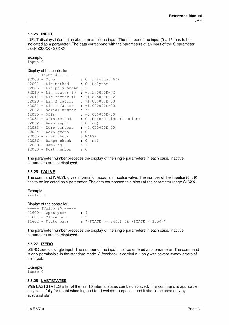
Reference Manual LMF
LMF V7.0 Page 31
5.5.25 INPUT
INPUT displays information about an analogue input. The number of the input (0 .. 19) has to be indicated as a parameter. The data correspond with the parameters of an input of the S-parameter block S2XXX / S3XXX. Example: input 0
Display of the controller: ----- Input #0 -----
S2000 - Type : 0 (internal AI)
S2001 - Lin method : 0 (Polynom)
S2005 - Lin poly order : 1
S2010 - Lin factor #0 : -7.500000E+02
S2011 - Lin factor #1 : +1.875000E+02
S2020 - Lin X factor : +1.000000E+00
S2021 - Lin Y factor : +1.000000E+00
S2022 - Serial number : ""
S2030 - Offs : +0.000000E+00
S2031 - Offs method : 0 (before linearization)
S2032 - Zero input : 0 (no)
S2033 - Zero timeout : +0.000000E+00
S2034 - Zero group : 0
S2035 - 4 mA Check : FALSE
S2036 - Range check : 0 (no)
S2039 - Damping : 1
S2050 - Port number : 0
The parameter number precedes the display of the single parameters in each case. Inactive parameters are not displayed.
5.5.26 IVALVE
The command IVALVE gives information about an impulse valve. The number of the impulse (0 .. 9) has to be indicated as a parameter. The data correspond to a block of the parameter range S16XX. Example: ivalve 0
Display of the controller: ----- IValve #0 -----
S1600 - Open port : 4
S1601 - Close port : 5
S1602 - State expr : "(STATE >= 2400) && (STATE < 2500)"
The parameter number precedes the display of the single parameters in each case. Inactive parameters are not displayed.
5.5.27 IZERO
IZERO zeros a single input. The number of the input must be entered as a parameter. The command is only permissible in the standard mode. A feedback is carried out only with severe syntax errors of the input. Example: izero 0
5.5.28 LASTSTATES
With LASTSTATES a list of the last 10 internal states can be displayed. This command is applicable only sensefully for troubleshooting and for developer purposes, and it should be used only by specialist staff.
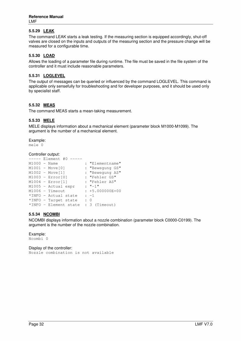
Reference Manual LMF
Page 32 LMF V7.0
5.5.29 LEAK
The command LEAK starts a leak testing. If the measuring section is equipped accordingly, shut-off valves are closed on the inputs and outputs of the measuring section and the pressure change will be measured for a configurable time.
5.5.30 LOAD
Allows the loading of a parameter file during runtime. The file must be saved in the file system of the controller and it must include reasonable parameters.
5.5.31 LOGLEVEL
The output of messages can be queried or influenced by the command LOGLEVEL. This command is applicable only sensefully for troubleshooting and for developer purposes, and it should be used only by specialist staff.
5.5.32 MEAS
The command MEAS starts a mean-taking measurement.
5.5.33 MELE
MELE displays information about a mechanical element (parameter block M1000-M1099). The argument is the number of a mechanical element. Example: mele 0
Controller output: ----- Element #0 -----
M1000 - Name : "Elementname"
M1001 - Move[0] : "Bewegung GS"
M1002 - Move[1] : "Bewegung AS"
M1003 - Error[0] : "Fehler GS"
M1004 - Error[1] : "Fehler AS"
M1005 - Actual expr : "-1"
M1006 - Timeout : +5.000000E+00
*INFO - Actual state : -1
*INFO - Target state : 0
*INFO - Element state : 3 (Timeout)
5.5.34 NCOMBI
NCOMBI displays information about a nozzle combination (parameter block C0000-C0199). The argument is the number of the nozzle combination. Example: Ncombi 0
Display of the controller: Nozzle combination is not available
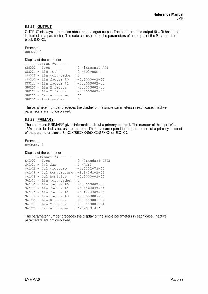
Reference Manual LMF
LMF V7.0 Page 33
5.5.35 OUTPUT
OUTPUT displays information about an analogue output. The number of the output (0 .. 9) has to be indicated as a parameter. The data correspond to the parameters of an output of the S-parameter block S8XXX. Example: output 0
Display of the controller: ----- Output #0 -----
S8000 - Type : 0 (internal AO)
S8001 - Lin method : 0 (Polynom)
S8005 - Lin poly order : 1
S8010 - Lin factor #0 : +0.000000E+00
S8011 - Lin factor #1 : +1.000000E+00
S8020 - Lin X factor : +1.000000E+00
S8021 - Lin Y factor : +1.000000E+00
S8022 - Serial number : ""
S8050 - Port number : 0
The parameter number precedes the display of the single parameters in each case. Inactive parameters are not displayed.
5.5.36 PRIMARY
The command PRIMARY gives information about a primary element. The number of the input (0 .. 139) has to be indicated as a parameter. The data correspond to the parameters of a primary element of the parameter blocks S4XXX/S5XXX/S6XXX/S7XXX or EXXXX. Example: primary 1
Display of the controller: ----- Primary #1 -----
S4100 - Type : 0 (Standard LFE)
S4101 - Cal Gas : 1 (Air)
S4102 - Cal pressure : +1.013207E+05
S4103 - Cal temperature: +2.942610E+02
S4104 - Cal humidity : +0.000000E+00
S4105 - Lin poly order : 3
S4110 - Lin factor #0 : +0.000000E+00
S4111 - Lin factor #1 : +5.536489E-04
S4112 - Lin factor #2 : -5.144490E-07
S4113 - Lin factor #3 : +0.000000E+00
S4120 - Lin X factor : +1.000000E-02
S4121 - Lin Y factor : +6.000000E+04
S4122 - Serial number : "752970-J9"
The parameter number precedes the display of the single parameters in each case. Inactive parameters are not displayed.
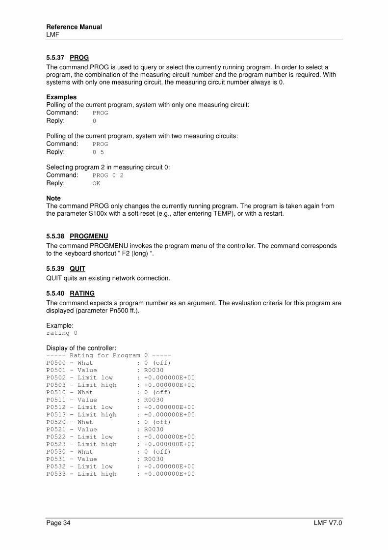
Reference Manual LMF
Page 34 LMF V7.0
5.5.37 PROG
The command PROG is used to query or select the currently running program. In order to select a program, the combination of the measuring circuit number and the program number is required. With systems with only one measuring circuit, the measuring circuit number always is 0. Examples Polling of the current program, system with only one measuring circuit: Command: PROG Reply: 0 Polling of the current program, system with two measuring circuits: Command: PROG Reply: 0 5 Selecting program 2 in measuring circuit 0: Command: PROG 0 2 Reply: OK Note The command PROG only changes the currently running program. The program is taken again from the parameter S100x with a soft reset (e.g., after entering TEMP), or with a restart.
5.5.38 PROGMENU
The command PROGMENU invokes the program menu of the controller. The command corresponds to the keyboard shortcut ” F2 (long) “.
5.5.39 QUIT
QUIT quits an existing network connection.
5.5.40 RATING
The command expects a program number as an argument. The evaluation criteria for this program are displayed (parameter Pn500 ff.). Example: rating 0
Display of the controller: ----- Rating for Program 0 -----
P0500 - What : 0 (off)
P0501 - Value : R0030
P0502 - Limit low : +0.000000E+00
P0503 - Limit high : +0.000000E+00
P0510 - What : 0 (off)
P0511 - Value : R0030
P0512 - Limit low : +0.000000E+00
P0513 - Limit high : +0.000000E+00
P0520 - What : 0 (off)
P0521 - Value : R0030
P0522 - Limit low : +0.000000E+00
P0523 - Limit high : +0.000000E+00
P0530 - What : 0 (off)
P0531 - Value : R0030
P0532 - Limit low : +0.000000E+00
P0533 - Limit high : +0.000000E+00
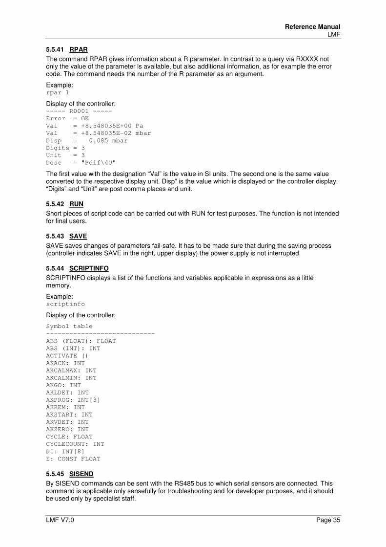
Reference Manual LMF
LMF V7.0 Page 35
5.5.41 RPAR
The command RPAR gives information about a R parameter. In contrast to a query via RXXXX not only the value of the parameter is available, but also additional information, as for example the error code. The command needs the number of the R parameter as an argument.
Example: rpar 1
Display of the controller: ----- R0001 -----
Error = OK
Val = +8.548035E+00 Pa
Val = +8.548035E-02 mbar
Disp = 0.085 mbar
Digits = 3
Unit = 3
Desc = "Pdif\4U"
The first value with the designation “Val” is the value in SI units. The second one is the same value converted to the respective display unit. Disp” is the value which is displayed on the controller display. “Digits” and “Unit” are post comma places and unit.
5.5.42 RUN
Short pieces of script code can be carried out with RUN for test purposes. The function is not intended for final users.
5.5.43 SAVE
SAVE saves changes of parameters fail-safe. It has to be made sure that during the saving process (controller indicates SAVE in the right, upper display) the power supply is not interrupted.
5.5.44 SCRIPTINFO
SCRIPTINFO displays a list of the functions and variables applicable in expressions as a little memory.
Example: scriptinfo
Display of the controller:
Symbol table
----------------------------
ABS (FLOAT): FLOAT
ABS (INT): INT
ACTIVATE ()
AKACK: INT
AKCALMAX: INT
AKCALMIN: INT
AKGO: INT
AKLDET: INT
AKPROG: INT[3]
AKREM: INT
AKSTART: INT
AKVDET: INT
AKZERO: INT
CYCLE: FLOAT
CYCLECOUNT: INT
DI: INT[8]
E: CONST FLOAT
5.5.45 SISEND
By SISEND commands can be sent with the RS485 bus to which serial sensors are connected. This command is applicable only sensefully for troubleshooting and for developer purposes, and it should be used only by specialist staff.
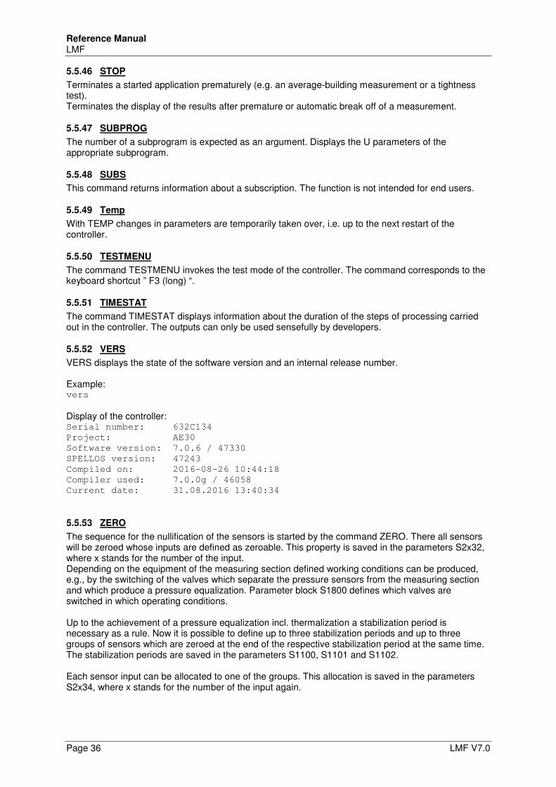
Reference Manual LMF
Page 36 LMF V7.0
5.5.46 STOP
Terminates a started application prematurely (e.g. an average-building measurement or a tightness test). Terminates the display of the results after premature or automatic break off of a measurement.
5.5.47 SUBPROG
The number of a subprogram is expected as an argument. Displays the U parameters of the appropriate subprogram.
5.5.48 SUBS
This command returns information about a subscription. The function is not intended for end users.
5.5.49 Temp
With TEMP changes in parameters are temporarily taken over, i.e. up to the next restart of the controller.
5.5.50 TESTMENU
The command TESTMENU invokes the test mode of the controller. The command corresponds to the keyboard shortcut ” F3 (long) “.
5.5.51 TIMESTAT
The command TIMESTAT displays information about the duration of the steps of processing carried out in the controller. The outputs can only be used sensefully by developers.
5.5.52 VERS
VERS displays the state of the software version and an internal release number. Example: vers
Display of the controller: Serial number: 632C134
Project: AE30
Software version: 7.0.6 / 47330
SPELLOS version: 47243
Compiled on: 2016-08-26 10:44:18
Compiler used: 7.0.0g / 46058
Current date: 31.08.2016 13:40:34
5.5.53 ZERO
The sequence for the nullification of the sensors is started by the command ZERO. There all sensors will be zeroed whose inputs are defined as zeroable. This property is saved in the parameters S2x32, where x stands for the number of the input. Depending on the equipment of the measuring section defined working conditions can be produced, e.g., by the switching of the valves which separate the pressure sensors from the measuring section and which produce a pressure equalization. Parameter block S1800 defines which valves are switched in which operating conditions. Up to the achievement of a pressure equalization incl. thermalization a stabilization period is necessary as a rule. Now it is possible to define up to three stabilization periods and up to three groups of sensors which are zeroed at the end of the respective stabilization period at the same time. The stabilization periods are saved in the parameters S1100, S1101 and S1102. Each sensor input can be allocated to one of the groups. This allocation is saved in the parameters S2x34, where x stands for the number of the input again.
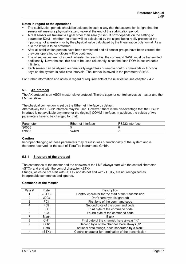
Reference Manual LMF
LMF V7.0 Page 37
Notes in regard of the operations
• The stabilization periods should be selected in such a way that the assumption is right that the sensor will measure physically a zero value at the end of the stabilization period.
• A real sensor will transmit a signal other than zero (offset). It now depends on the setting of parameter S2x31 whether the offset will be calculated by the signal being really present at the input (e.g., of a tension), or by the physical value calculated by the linearization polynomial. As a rule the latter is to be preferred.
• After all stabilization periods have been terminated and all sensor groups have been zeroed, the previous operating conditions will be continued.
• The offset values are not stored fail-safe. To reach this, the command SAVE must be transmitted additionally. Nevertheless, this has to be used reluctantly, since the flash ROM is not writeable infinitely.
• Each sensor can be aligned automatically regardless of remote control commands or function keys on the system in solid time intervals. The interval is saved in the parameter S2x33.
For further information and notes in regard of requirements of the nullification see chapter 7.4.2
5.6 AK protocol
The AK protocol is an ASCII master slave protocol. There a superior control serves as master and the LMF as slave. The physical connection is set by the Ethernet interface by default. Alternatively the RS232 interface may be used. However, there is the disadvantage that the RS232 interface is not available any more for the (logical) COMM interface. In addition, the values of two parameters have to be changed for that: Parameter Ethernet interface RS232 interface S0006 5 0 S9600 54489 -1 Caution Improper changing of these parameters may result in loss of functionality of the system and is therefore reserved for the staff of TetraTec Instruments GmbH.
5.6.1 Structure of the protocol
The commands of the master and the answers of the LMF always start with the control character <STX> and end with the control character <ETX>. Strings, which do not start with <STX> and do not end with <ETX>, are not recognized as interpretable commands and ignored. Command of the master
Byte # Byte Description 1 <STX> Control character for the start of the transmission 2 <DC> Don’t care byte (is ignored) 3 FC1 First byte of the command code 4 FC2 Second byte of the command code 5 FC3 Third byte of the command code 6 FC4 Fourth byte of the command code 7 Blank Blank 8 CH1 First byte of the channel, here always “K” 9 CH2 Second byte of the channel, here always „0“ Data optional data strings, each separated by a blank n <ETX> Control character for termination of the transmission
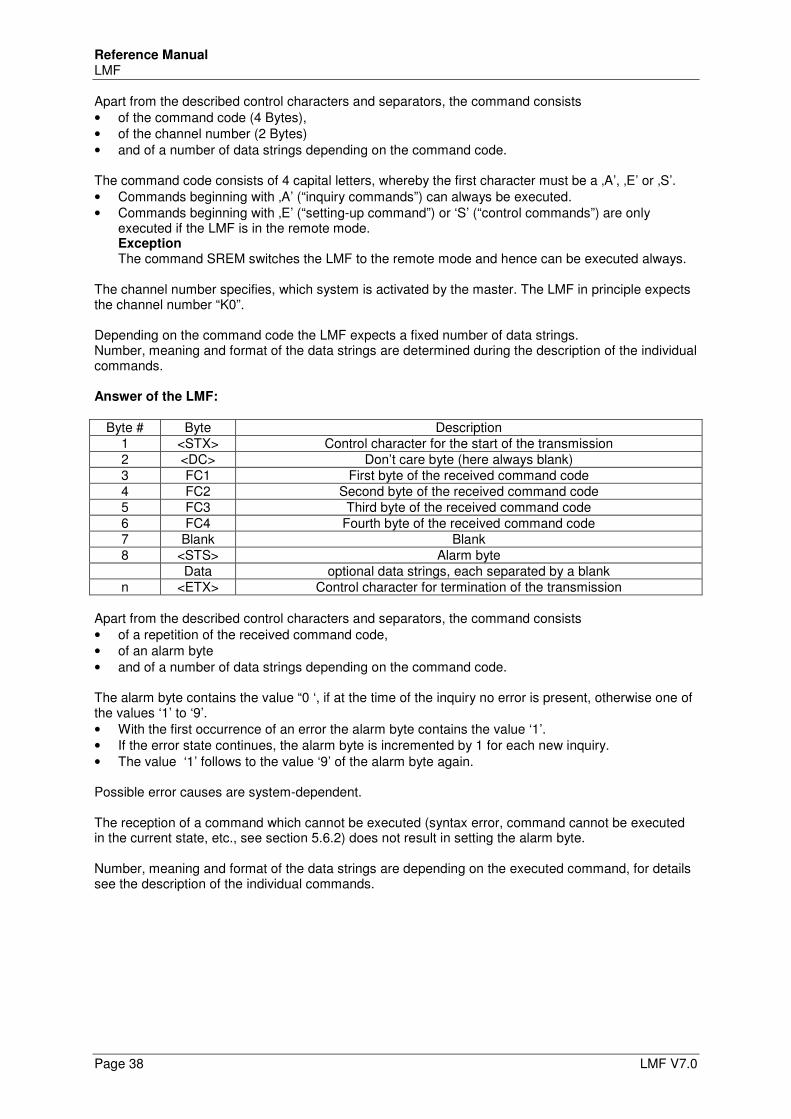
Reference Manual LMF
Page 38 LMF V7.0
Apart from the described control characters and separators, the command consists • of the command code (4 Bytes), • of the channel number (2 Bytes) • and of a number of data strings depending on the command code. The command code consists of 4 capital letters, whereby the first character must be a ‚A’, ‚E’ or ‚S’. • Commands beginning with ‚A’ (“inquiry commands”) can always be executed. • Commands beginning with ‚E’ (“setting-up command”) or ‘S’ (“control commands”) are only
executed if the LMF is in the remote mode. Exception The command SREM switches the LMF to the remote mode and hence can be executed always.
The channel number specifies, which system is activated by the master. The LMF in principle expects the channel number “K0”. Depending on the command code the LMF expects a fixed number of data strings. Number, meaning and format of the data strings are determined during the description of the individual commands. Answer of the LMF:
Byte # Byte Description 1 <STX> Control character for the start of the transmission 2 <DC> Don’t care byte (here always blank) 3 FC1 First byte of the received command code 4 FC2 Second byte of the received command code 5 FC3 Third byte of the received command code 6 FC4 Fourth byte of the received command code 7 Blank Blank 8 <STS> Alarm byte Data optional data strings, each separated by a blank n <ETX> Control character for termination of the transmission
Apart from the described control characters and separators, the command consists • of a repetition of the received command code, • of an alarm byte • and of a number of data strings depending on the command code. The alarm byte contains the value “0 ‘, if at the time of the inquiry no error is present, otherwise one of the values ‘1’ to ‘9’. • With the first occurrence of an error the alarm byte contains the value ‘1’. • If the error state continues, the alarm byte is incremented by 1 for each new inquiry. • The value ‘1’ follows to the value ‘9’ of the alarm byte again. Possible error causes are system-dependent. The reception of a command which cannot be executed (syntax error, command cannot be executed in the current state, etc., see section 5.6.2) does not result in setting the alarm byte. Number, meaning and format of the data strings are depending on the executed command, for details see the description of the individual commands.
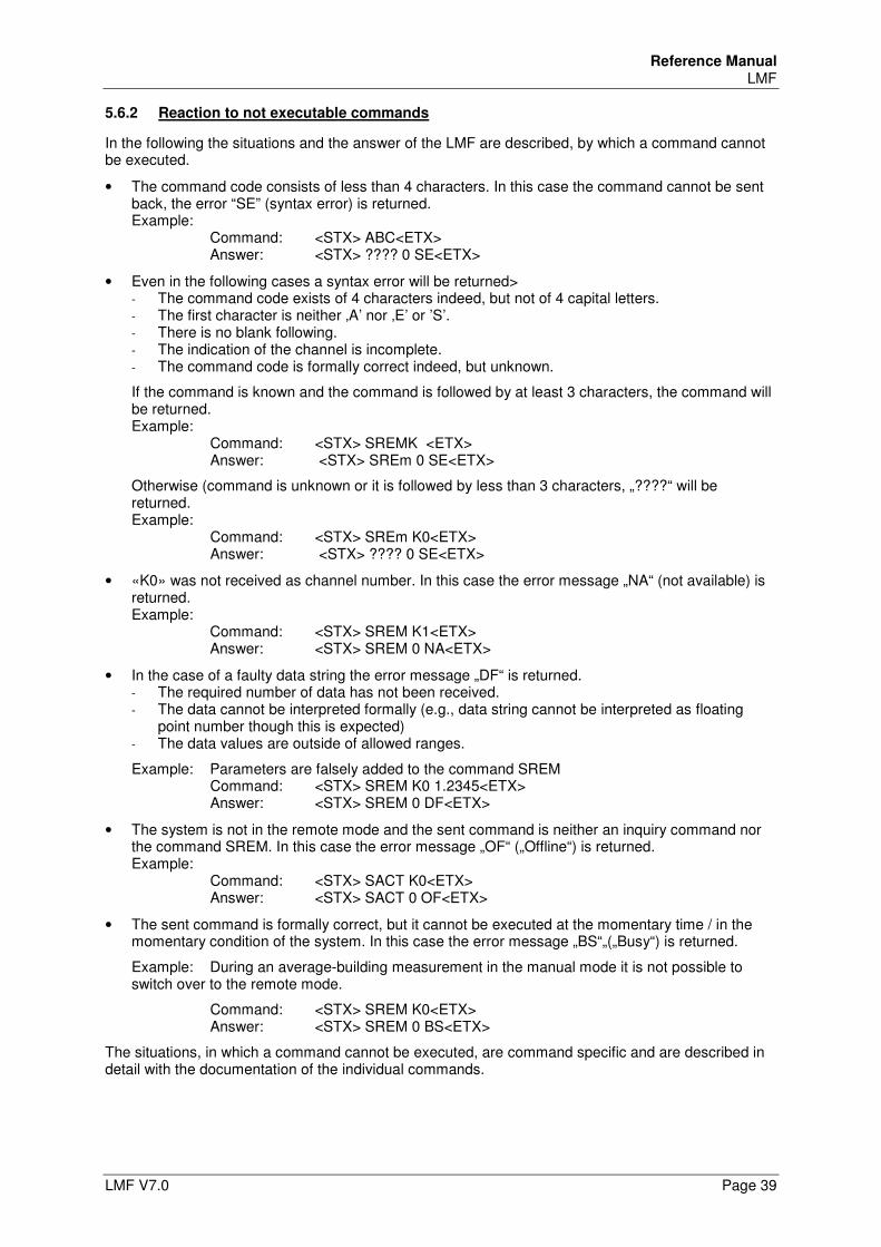
Reference Manual LMF
LMF V7.0 Page 39
5.6.2 Reaction to not executable commands
In the following the situations and the answer of the LMF are described, by which a command cannot be executed.
• The command code consists of less than 4 characters. In this case the command cannot be sent back, the error “SE” (syntax error) is returned. Example:
Command: <STX> ABC<ETX> Answer: <STX> ???? 0 SE<ETX>
• Even in the following cases a syntax error will be returned> - The command code exists of 4 characters indeed, but not of 4 capital letters. - The first character is neither ‚A’ nor ‚E’ or ’S’. - There is no blank following. - The indication of the channel is incomplete. - The command code is formally correct indeed, but unknown.
If the command is known and the command is followed by at least 3 characters, the command will be returned. Example:
Command: <STX> SREMK <ETX> Answer: <STX> SREm 0 SE<ETX>
Otherwise (command is unknown or it is followed by less than 3 characters, „????“ will be returned. Example:
Command: <STX> SREm K0<ETX> Answer: <STX> ???? 0 SE<ETX>
• «K0» was not received as channel number. In this case the error message „NA“ (not available) is returned. Example:
Command: <STX> SREM K1<ETX> Answer: <STX> SREM 0 NA<ETX>
• In the case of a faulty data string the error message „DF“ is returned. - The required number of data has not been received. - The data cannot be interpreted formally (e.g., data string cannot be interpreted as floating
point number though this is expected) - The data values are outside of allowed ranges.
Example: Parameters are falsely added to the command SREM Command: <STX> SREM K0 1.2345<ETX> Answer: <STX> SREM 0 DF<ETX>
• The system is not in the remote mode and the sent command is neither an inquiry command nor the command SREM. In this case the error message „OF“ („Offline“) is returned. Example:
Command: <STX> SACT K0<ETX> Answer: <STX> SACT 0 OF<ETX>
• The sent command is formally correct, but it cannot be executed at the momentary time / in the momentary condition of the system. In this case the error message „BS“„(„Busy“) is returned.
Example: During an average-building measurement in the manual mode it is not possible to switch over to the remote mode.
Command: <STX> SREM K0<ETX> Answer: <STX> SREM 0 BS<ETX>
The situations, in which a command cannot be executed, are command specific and are described in detail with the documentation of the individual commands.
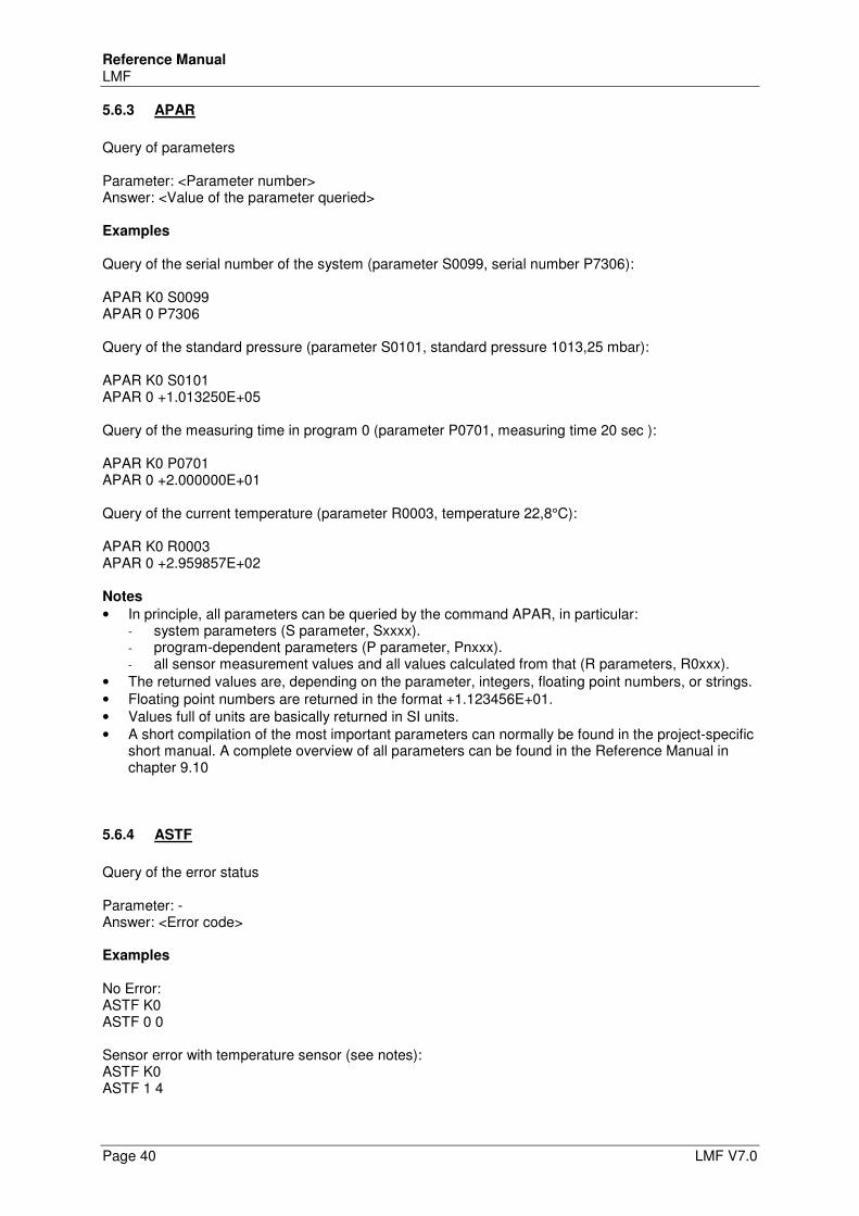
Reference Manual LMF
Page 40 LMF V7.0
5.6.3 APAR
Query of parameters Parameter: <Parameter number> Answer: <Value of the parameter queried> Examples Query of the serial number of the system (parameter S0099, serial number P7306): APAR K0 S0099 APAR 0 P7306 Query of the standard pressure (parameter S0101, standard pressure 1013,25 mbar): APAR K0 S0101 APAR 0 +1.013250E+05 Query of the measuring time in program 0 (parameter P0701, measuring time 20 sec ): APAR K0 P0701 APAR 0 +2.000000E+01 Query of the current temperature (parameter R0003, temperature 22,8°C): APAR K0 R0003 APAR 0 +2.959857E+02 Notes
• In principle, all parameters can be queried by the command APAR, in particular: - system parameters (S parameter, Sxxxx). - program-dependent parameters (P parameter, Pnxxx). - all sensor measurement values and all values calculated from that (R parameters, R0xxx).
• The returned values are, depending on the parameter, integers, floating point numbers, or strings. • Floating point numbers are returned in the format +1.123456E+01. • Values full of units are basically returned in SI units. • A short compilation of the most important parameters can normally be found in the project-specific
short manual. A complete overview of all parameters can be found in the Reference Manual in chapter 9.10
5.6.4 ASTF
Query of the error status Parameter: - Answer: <Error code> Examples No Error: ASTF K0 ASTF 0 0 Sensor error with temperature sensor (see notes): ASTF K0 ASTF 1 4
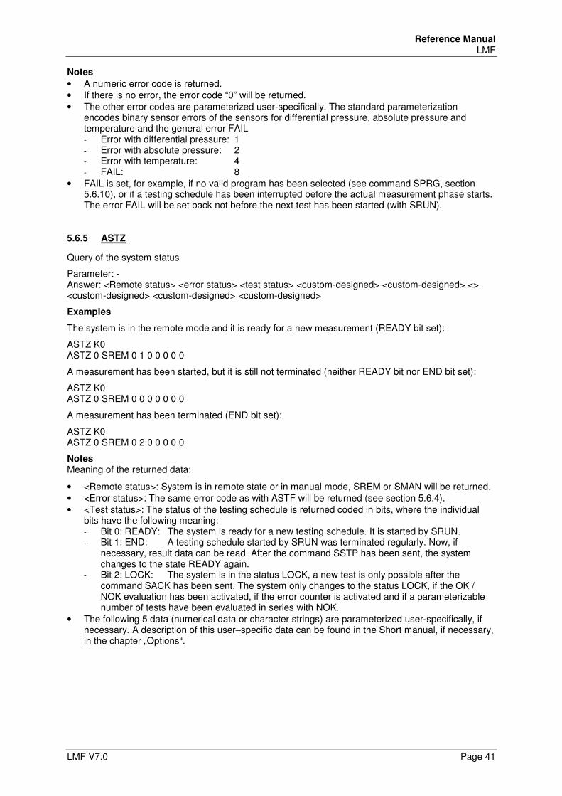
Reference Manual LMF
LMF V7.0 Page 41
Notes
• A numeric error code is returned. • If there is no error, the error code “0” will be returned. • The other error codes are parameterized user-specifically. The standard parameterization
encodes binary sensor errors of the sensors for differential pressure, absolute pressure and temperature and the general error FAIL - Error with differential pressure: 1 - Error with absolute pressure: 2 - Error with temperature: 4 - FAIL: 8
• FAIL is set, for example, if no valid program has been selected (see command SPRG, section 5.6.10), or if a testing schedule has been interrupted before the actual measurement phase starts. The error FAIL will be set back not before the next test has been started (with SRUN).
5.6.5 ASTZ
Query of the system status
Parameter: - Answer: <Remote status> <error status> <test status> <custom-designed> <custom-designed> <> <custom-designed> <custom-designed> <custom-designed>
Examples
The system is in the remote mode and it is ready for a new measurement (READY bit set):
ASTZ K0 ASTZ 0 SREM 0 1 0 0 0 0 0
A measurement has been started, but it is still not terminated (neither READY bit nor END bit set):
ASTZ K0 ASTZ 0 SREM 0 0 0 0 0 0 0
A measurement has been terminated (END bit set):
ASTZ K0 ASTZ 0 SREM 0 2 0 0 0 0 0
Notes Meaning of the returned data:
• <Remote status>: System is in remote state or in manual mode, SREM or SMAN will be returned. • <Error status>: The same error code as with ASTF will be returned (see section 5.6.4). • <Test status>: The status of the testing schedule is returned coded in bits, where the individual
bits have the following meaning: - Bit 0: READY: The system is ready for a new testing schedule. It is started by SRUN. - Bit 1: END: A testing schedule started by SRUN was terminated regularly. Now, if
necessary, result data can be read. After the command SSTP has been sent, the system changes to the state READY again.
- Bit 2: LOCK: The system is in the status LOCK, a new test is only possible after the command SACK has been sent. The system only changes to the status LOCK, if the OK / NOK evaluation has been activated, if the error counter is activated and if a parameterizable number of tests have been evaluated in series with NOK.
• The following 5 data (numerical data or character strings) are parameterized user-specifically, if necessary. A description of this user–specific data can be found in the Short manual, if necessary, in the chapter „Options“.
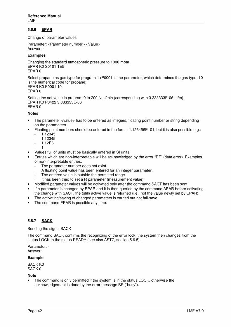
Reference Manual LMF
Page 42 LMF V7.0
5.6.6 EPAR
Change of parameter values
Parameter: <Parameter number> <Value> Answer: -
Examples
Changing the standard atmospheric pressure to 1000 mbar: EPAR K0 S0101 1E5 EPAR 0
Select propane as gas type for program 1 (P0001 is the parameter, which determines the gas type, 10 is the numerical code for propane): EPAR K0 P0001 10 EPAR 0
Setting the set value in program 0 to 200 Nml/min (corresponding with 3.333333E-06 m³/s) EPAR K0 P0422 3.333333E-06 EPAR 0
Notes
• The parameter <value> has to be entered as integers, floating point number or string depending on the parameters.
• Floating point numbers should be entered in the form +1.123456E+01, but it is also possible e.g.: - 1.12345 - 1.12345 - 1.12E6 - 1
• Values full of units must be basically entered in SI units. • Entries which are non-interpretable will be acknowledged by the error “DF” (data error). Examples
of non-interpretable entries: - The parameter number does not exist. - A floating point value has been entered for an integer parameter. - The entered value is outside the permitted range. - It has been tried to set a R parameter (measurement value).
• Modified parameter values will be activated only after the command SACT has been sent. • If a parameter is changed by EPAR and it is then queried by the command APAR before activating
the change with SACT, the (still) active value is returned (i.e., not the value newly set by EPAR). • The activating/saving of changed parameters is carried out not fail-save. • The command EPAR is possible any time.
5.6.7 SACK
Sending the signal SACK
The command SACK confirms the recognizing of the error lock, the system then changes from the status LOCK to the status READY (see also ASTZ, section 5.6.5).
Parameter: - Answer: -
Example
SACK K0 SACK 0
Note
• The command is only permitted if the system is in the status LOCK, otherwise the acknowledgement is done by the error message BS (“busy”).
Reference Manual LMF
LMF V7.0 Page 43
5.6.8 SACT
Activation of changed parameters Parameter: - Answer: - Example SACT K0 SACT 0 Notes
• Parameters, which have been changed by EPAR, are activated by the command SACT. • The command is always possible in the remote mode, even during a running test. • The changes are not stored fail-safe.
5.6.9 SMAN
Activate manual mode Parameter: - Answer: - Example SMAN K0 SMAN 0 Note
• The command is possible only if the system is in the status READY (see command ASTZ, section 5.6.5), i.e., not during a running test.
5.6.10 SPRG
Setting of the program Parameter: <Program> Answer: - Example Switch to program 3: SPRG K0 3 SPRG 0 Notes
• Programs 0 to 9 are permitted • For systems with 2 (3) measuring circuits 2 (3) parameters are required (first parameter for
measuring circuit 0, second for measuring circuit 1 ...) • Before a testing schedule is started for the first time with (SRUN) a program has to be selected
with SPRG. If no program has been selected, the error FAIL will be set after execution of SRUN (see command ASTF, section 5.6.4).
Reference Manual LMF
Page 44 LMF V7.0
5.6.11 SREM
Activate remote mode Parameter: - Answer: - Example SREM K0 SREM 0 Note
• The command is effective only if the system is in the status READY (see command ASTZ, section 5.6.5), i.e. not during a test which has been started manually by the operator (by keystroke). Otherwise the acknowledgement is done by BS (“busy”).
5.6.12 SRUN
Start measuring run
Parameter: <Special function> Answer: -
Example
SRUN K0 0 SRUN 0
Notes
• The parameter <special function> transmits with a bit-code, which (additional) special functions are carried out in the following testing schedule. Possible special functions: - Bit 0: ZERO: Carry out nullification. - Bit 1: CALMIN: only relevant with geometric measurement systems. - Bit 2: CALMAX: only relevant with geometric measurement systems. - Bit 3: LDET: only relevant with leak measurement systems. - Bit 4: VDET: only relevant with leak measurement systems.
• The command is only permitted if the system is in the status READY.
5.6.13 SSTP
Terminate testing schedule Parameter: -
Answer: -
Example
SSTP K0 SSTP 0
Notes
• If the command SSTP is sent during a running test, the test will be cancelled or prematurely terminated, then the system switches to the status END and then to the status READY (see command ASTZ, section 5.6.5).
• If the command SSTP is sent after the regular end of a test (the system is in the status END then), the system changes to the status READY.
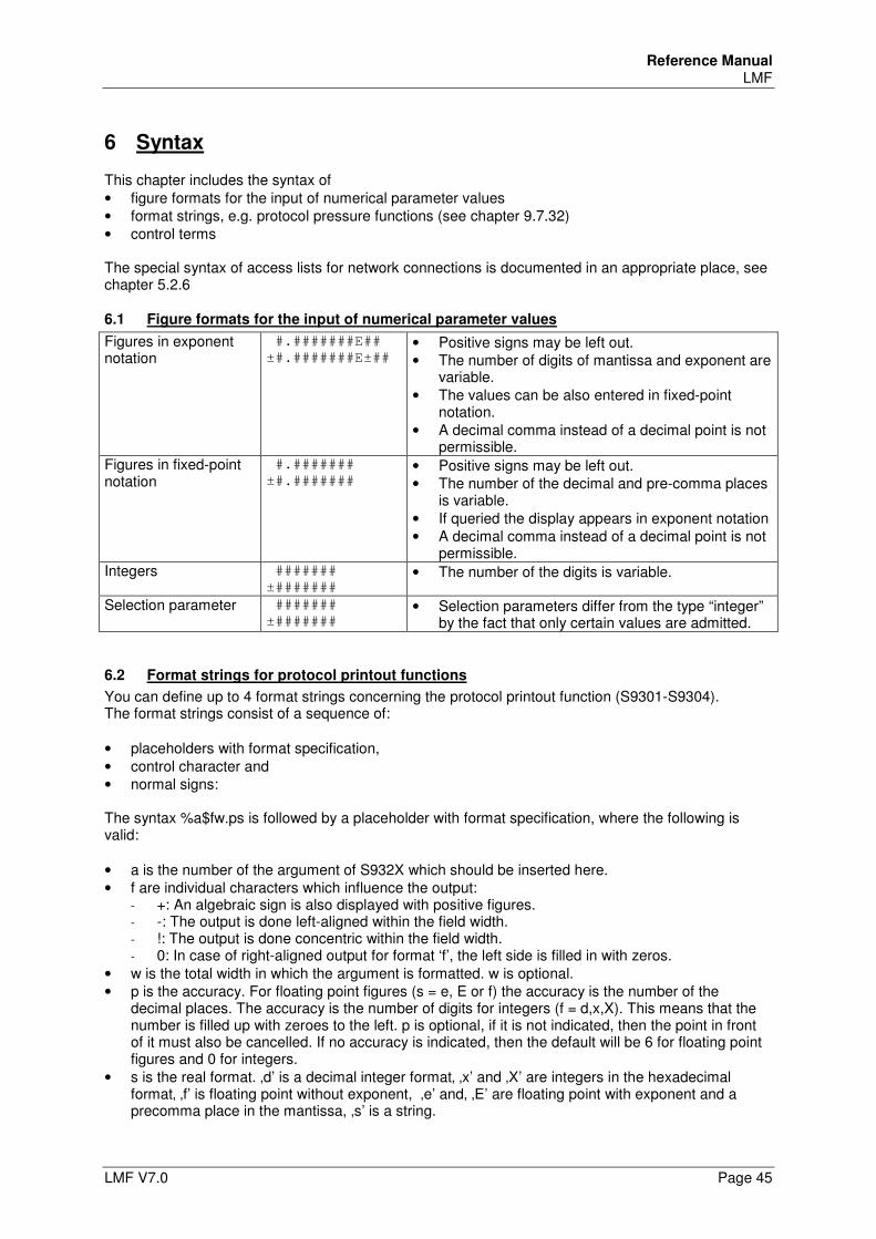
Reference Manual LMF
LMF V7.0 Page 45
6 Syntax
This chapter includes the syntax of • figure formats for the input of numerical parameter values • format strings, e.g. protocol pressure functions (see chapter 9.7.32) • control terms The special syntax of access lists for network connections is documented in an appropriate place, see chapter 5.2.6
6.1 Figure formats for the input of numerical parameter values
Figures in exponent notation
#.#######E##
±#.#######E±## • Positive signs may be left out. • The number of digits of mantissa and exponent are
variable. • The values can be also entered in fixed-point
notation. • A decimal comma instead of a decimal point is not
permissible. Figures in fixed-point notation
#.#######
±#.####### • Positive signs may be left out. • The number of the decimal and pre-comma places
is variable. • If queried the display appears in exponent notation • A decimal comma instead of a decimal point is not
permissible. Integers #######
±####### • The number of the digits is variable.
Selection parameter #######
±####### • Selection parameters differ from the type “integer”
by the fact that only certain values are admitted.
6.2 Format strings for protocol printout functions
You can define up to 4 format strings concerning the protocol printout function (S9301-S9304). The format strings consist of a sequence of: • placeholders with format specification, • control character and • normal signs: The syntax %a$fw.ps is followed by a placeholder with format specification, where the following is valid: • a is the number of the argument of S932X which should be inserted here. • f are individual characters which influence the output:
- +: An algebraic sign is also displayed with positive figures. - -: The output is done left-aligned within the field width. - !: The output is done concentric within the field width. - 0: In case of right-aligned output for format ‘f’, the left side is filled in with zeros.
• w is the total width in which the argument is formatted. w is optional. • p is the accuracy. For floating point figures (s = e, E or f) the accuracy is the number of the
decimal places. The accuracy is the number of digits for integers (f = d,x,X). This means that the number is filled up with zeroes to the left. p is optional, if it is not indicated, then the point in front of it must also be cancelled. If no accuracy is indicated, then the default will be 6 for floating point figures and 0 for integers.
• s is the real format. ‚d’ is a decimal integer format‚ ‚x’ and ‚X’ are integers in the hexadecimal format‚ ‚f’ is floating point without exponent, ‚e’ and‚ ‚E’ are floating point with exponent and a precomma place in the mantissa, ‚s’ is a string.
Reference Manual LMF
Page 46 LMF V7.0
Control character Control characters are initiated with a backslash. The following control characters are available: • \t Tab character. • \\ backslash • \r carriage return • \n linefeed Normal characters All characters not recognized as control characters or as a format specification are copied 1:1 in the output. Example placeholders with format specification for protocol printout function • „%2$d“displays the value of S9322 as an integer: „42“. • „%2$0.4d“ displays the value of S9322 as an integer with 4 places and leading zeros: „0042“. • „%2$+0.4d“ displays the value of S9322 as an integer with 4 places, leading zeros and an
algebraic sign even with positive figures: „+042“. • „%2$+010.4d“ displays the value of S9322 as an integer with 4 places, leading zeros, an algebraic
sign even with positive figures, and a total width of 10 signs: „ +042“. • „%2$-2+010.4d” displays the value of S9322 as an integer with 4 places, leading zeros, an
algebraic sign even with positive figures, and a total width of 10 signs left-aligned: „+042 “. • „%0$.3f“ displays the value of S9320 as a floating point figure with 3 decimal places: „42.000“. • „%0$E“ displays the value of S9320 as a floating point figure with 6 decimal places:
„4.200000E01“. • „%0$.3e“ displays the value of S9320 as a floating point figure with 3 decimal places: „4.200E01“. Note In other contexts the format specifications can be used the same way without the first two characters.
6.3 Control terms
To be able to customize the system easier to different application scenarios, terms are used at many places for the determination of input or output signals. The calculation is carried out within these terms and access to inputs or status variables used in the software is possible.
6.3.1 Types
Operands of different types are processed in terms. Available types are: INTEGER (integer values), FLOAT (floating point values) and STRING (strings). An automatic conversion of the types into each other will not be carried out!
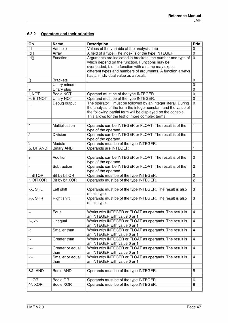
Reference Manual LMF
LMF V7.0 Page 47
6.3.2 Operators and their priorities
Op Name Description Prio
Id Variable Values of the variable at the analysis time 0 Id[] Array A field of a type. The index is of the type INTEGER. 0 Id() Function Arguments are indicated in brackets, the number and type of
which depend on the function. Functions may be overloaded, i. e., a function with a name may expect different types and numbers of arguments. A function always has an individual value as a result.
0
() Brackets 0 - Unary minus 0 + Unary plus 0 !, NOT Boole NOT Operand must be of the type INTEGER. 0 ~, BITNOT Unary NOT Operand must be of the type INTEGER. 0 _ Debug output The operator _ must be followed by an integer literal. During
the analysis of the term the integer constant and the value of the following partial term will be displayed on the console. This allows for the test of more complex terms.
0
* Multiplication Operands can be INTEGER or FLOAT. The result is of the
type of the operand. 1
/ Division Operands can be INTEGER or FLOAT. The result is of the type of the operand.
1
\ Modulo Operands must be of the type INTEGER. 1 &, BITAND Binary AND Operands are INTEGER 1 + Addition Operands can be INTEGER or FLOAT. The result is of the
type of the operand. 2
- Subtraction Operands can be INTEGER or FLOAT. The result is of the type of the operand.
2
|, BITOR Bit by bit OR Operands must be of the type INTEGER. 2 ^, BITXOR Bit by bit XOR Operands must be of the type INTEGER. 2 <<, SHL Left shift Operands must be of the type INTEGER. The result is also
of this type. 3
>>, SHR Right shift Operands must be of the type INTEGER. The result is also of this type.
3
= Equal Works with INTEGER or FLOAT as operands. The result is
an INTEGER with value 0 or 1. 4
!=, <> Unequal Works with INTEGER or FLOAT as operands. The result is an INTEGER with value 0 or 1.
4
< Smaller than Works with INTEGER or FLOAT as operands. The result is an INTEGER with value 0 or 1.
4
> Greater than Works with INTEGER or FLOAT as operands. The result is an INTEGER with value 0 or 1.
4
>= Greater or equal than
Works with INTEGER or FLOAT as operands. The result is an INTEGER with value 0 or 1.
4
<= Smaller or equal than
Works with INTEGER or FLOAT as operands. The result is an INTEGER with value 0 or 1.
4
&&, AND Boole AND Operands must be of the type INTEGER. 5 ||, OR Boole OR Operands must be of the type INTEGER. 6 ^^, XOR Boole XOR Operands must be of the type INTEGER. 6
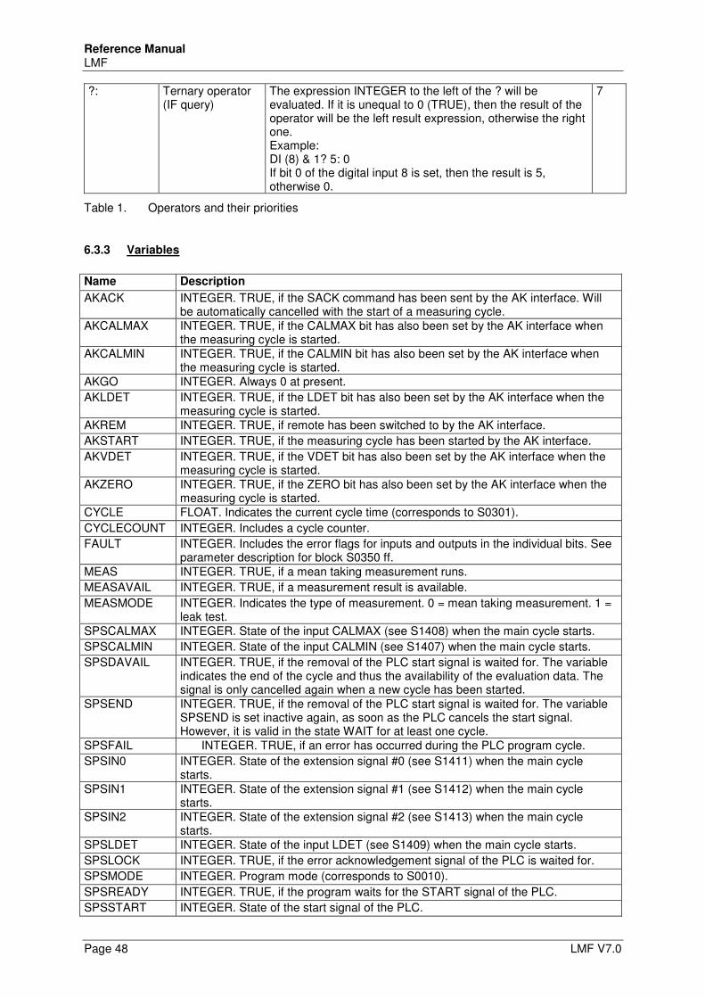
Reference Manual LMF
Page 48 LMF V7.0
?: Ternary operator (IF query)
The expression INTEGER to the left of the ? will be evaluated. If it is unequal to 0 (TRUE), then the result of the operator will be the left result expression, otherwise the right one. Example: DI (8) & 1? 5: 0 If bit 0 of the digital input 8 is set, then the result is 5, otherwise 0.
7
Table 1. Operators and their priorities
6.3.3 Variables
Name Description
AKACK INTEGER. TRUE, if the SACK command has been sent by the AK interface. Will be automatically cancelled with the start of a measuring cycle.
AKCALMAX INTEGER. TRUE, if the CALMAX bit has also been set by the AK interface when the measuring cycle is started.
AKCALMIN INTEGER. TRUE, if the CALMIN bit has also been set by the AK interface when the measuring cycle is started.
AKGO INTEGER. Always 0 at present.
AKLDET INTEGER. TRUE, if the LDET bit has also been set by the AK interface when the measuring cycle is started.
AKREM INTEGER. TRUE, if remote has been switched to by the AK interface.
AKSTART INTEGER. TRUE, if the measuring cycle has been started by the AK interface.
AKVDET INTEGER. TRUE, if the VDET bit has also been set by the AK interface when the measuring cycle is started.
AKZERO INTEGER. TRUE, if the ZERO bit has also been set by the AK interface when the measuring cycle is started.
CYCLE FLOAT. Indicates the current cycle time (corresponds to S0301).
CYCLECOUNT INTEGER. Includes a cycle counter.
FAULT INTEGER. Includes the error flags for inputs and outputs in the individual bits. See parameter description for block S0350 ff.
MEAS INTEGER. TRUE, if a mean taking measurement runs.
MEASAVAIL INTEGER. TRUE, if a measurement result is available.
MEASMODE INTEGER. Indicates the type of measurement. 0 = mean taking measurement. 1 = leak test.
SPSCALMAX INTEGER. State of the input CALMAX (see S1408) when the main cycle starts.
SPSCALMIN INTEGER. State of the input CALMIN (see S1407) when the main cycle starts.
SPSDAVAIL INTEGER. TRUE, if the removal of the PLC start signal is waited for. The variable indicates the end of the cycle and thus the availability of the evaluation data. The signal is only cancelled again when a new cycle has been started.
SPSEND INTEGER. TRUE, if the removal of the PLC start signal is waited for. The variable SPSEND is set inactive again, as soon as the PLC cancels the start signal. However, it is valid in the state WAIT for at least one cycle.
SPSFAIL INTEGER. TRUE, if an error has occurred during the PLC program cycle.
SPSIN0 INTEGER. State of the extension signal #0 (see S1411) when the main cycle starts.
SPSIN1 INTEGER. State of the extension signal #1 (see S1412) when the main cycle starts.
SPSIN2 INTEGER. State of the extension signal #2 (see S1413) when the main cycle starts.
SPSLDET INTEGER. State of the input LDET (see S1409) when the main cycle starts.
SPSLOCK INTEGER. TRUE, if the error acknowledgement signal of the PLC is waited for.
SPSMODE INTEGER. Program mode (corresponds to S0010).
SPSREADY INTEGER. TRUE, if the program waits for the START signal of the PLC.
SPSSTART INTEGER. State of the start signal of the PLC.
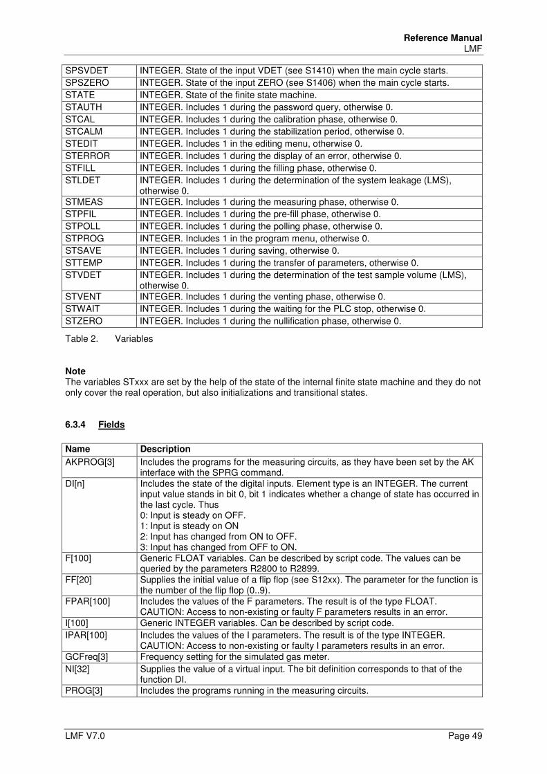
Reference Manual LMF
LMF V7.0 Page 49
SPSVDET INTEGER. State of the input VDET (see S1410) when the main cycle starts.
SPSZERO INTEGER. State of the input ZERO (see S1406) when the main cycle starts.
STATE INTEGER. State of the finite state machine.
STAUTH INTEGER. Includes 1 during the password query, otherwise 0.
STCAL INTEGER. Includes 1 during the calibration phase, otherwise 0.
STCALM INTEGER. Includes 1 during the stabilization period, otherwise 0.
STEDIT INTEGER. Includes 1 in the editing menu, otherwise 0.
STERROR INTEGER. Includes 1 during the display of an error, otherwise 0.
STFILL INTEGER. Includes 1 during the filling phase, otherwise 0.
STLDET INTEGER. Includes 1 during the determination of the system leakage (LMS), otherwise 0.
STMEAS INTEGER. Includes 1 during the measuring phase, otherwise 0.
STPFIL INTEGER. Includes 1 during the pre-fill phase, otherwise 0.
STPOLL INTEGER. Includes 1 during the polling phase, otherwise 0.
STPROG INTEGER. Includes 1 in the program menu, otherwise 0.
STSAVE INTEGER. Includes 1 during saving, otherwise 0.
STTEMP INTEGER. Includes 1 during the transfer of parameters, otherwise 0.
STVDET INTEGER. Includes 1 during the determination of the test sample volume (LMS), otherwise 0.
STVENT INTEGER. Includes 1 during the venting phase, otherwise 0.
STWAIT INTEGER. Includes 1 during the waiting for the PLC stop, otherwise 0.
STZERO INTEGER. Includes 1 during the nullification phase, otherwise 0.
Table 2. Variables
Note The variables STxxx are set by the help of the state of the internal finite state machine and they do not only cover the real operation, but also initializations and transitional states.
6.3.4 Fields
Name Description
AKPROG[3] Includes the programs for the measuring circuits, as they have been set by the AK interface with the SPRG command.
DI[n] Includes the state of the digital inputs. Element type is an INTEGER. The current input value stands in bit 0, bit 1 indicates whether a change of state has occurred in the last cycle. Thus 0: Input is steady on OFF. 1: Input is steady on ON 2: Input has changed from ON to OFF. 3: Input has changed from OFF to ON.
F[100] Generic FLOAT variables. Can be described by script code. The values can be queried by the parameters R2800 to R2899.
FF[20] Supplies the initial value of a flip flop (see S12xx). The parameter for the function is the number of the flip flop (0..9).
FPAR[100] Includes the values of the F parameters. The result is of the type FLOAT. CAUTION: Access to non-existing or faulty F parameters results in an error.
I[100] Generic INTEGER variables. Can be described by script code.
IPAR[100] Includes the values of the I parameters. The result is of the type INTEGER. CAUTION: Access to non-existing or faulty I parameters results in an error.
GCFreq[3] Frequency setting for the simulated gas meter.
NI[32] Supplies the value of a virtual input. The bit definition corresponds to that of the function DI.
PROG[3] Includes the programs running in the measuring circuits.
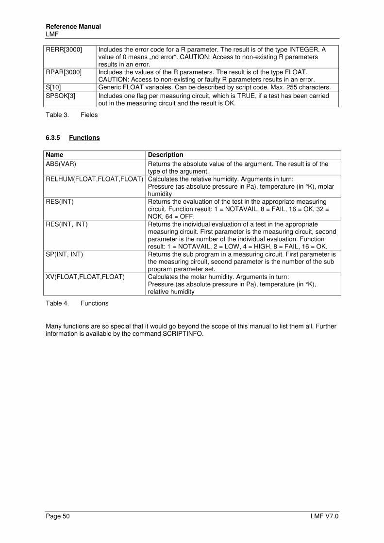
Reference Manual LMF
Page 50 LMF V7.0
RERR[3000] Includes the error code for a R parameter. The result is of the type INTEGER. A value of 0 means „no error“. CAUTION: Access to non-existing R parameters results in an error.
RPAR[3000] Includes the values of the R parameters. The result is of the type FLOAT. CAUTION: Access to non-existing or faulty R parameters results in an error.
S[10] Generic FLOAT variables. Can be described by script code. Max. 255 characters.
SPSOK[3] Includes one flag per measuring circuit, which is TRUE, if a test has been carried out in the measuring circuit and the result is OK.
Table 3. Fields
6.3.5 Functions
Name Description
ABS(VAR) Returns the absolute value of the argument. The result is of the type of the argument.
RELHUM(FLOAT,FLOAT,FLOAT) Calculates the relative humidity. Arguments in turn: Pressure (as absolute pressure in Pa), temperature (in °K), molar humidity
RES(INT) Returns the evaluation of the test in the appropriate measuring circuit. Function result: 1 = NOTAVAIL, 8 = FAIL, 16 = OK, 32 = NOK, 64 = OFF.
RES(INT, INT) Returns the individual evaluation of a test in the appropriate measuring circuit. First parameter is the measuring circuit, second parameter is the number of the individual evaluation. Function result: 1 = NOTAVAIL, 2 = LOW, 4 = HIGH, 8 = FAIL, 16 = OK.
SP(INT, INT) Returns the sub program in a measuring circuit. First parameter is the measuring circuit, second parameter is the number of the sub program parameter set.
XV(FLOAT,FLOAT,FLOAT) Calculates the molar humidity. Arguments in turn: Pressure (as absolute pressure in Pa), temperature (in °K), relative humidity
Table 4. Functions
Many functions are so special that it would go beyond the scope of this manual to list them all. Further information is available by the command SCRIPTINFO.
Reference Manual LMF
LMF V7.0 Page 51
7 Operating modes
This chapter explains the most important operational modes except the PLC mode. An own chapter is dedicated to the PLC operational mode, see chapter 16.
7.1 STANDARD MODE
The standard mode is the mode which is active after the switch-on. It is also active if one of the other modes has been quit. As a rule the lower display line is used in the standard mode to display the current measuring program. Nevertheless, this can be initialized and, hence, deviations are possible in this item. All arithmetic values and measurement values are continuously displayed in the standard mode. The displayed values can be toggled with the function keys “F1”, “F2” and “F3” starting from the default. The standard display setting is determined in the parameters and it can be changed in the editing mode.
7.1.1 Program selection
The LMF makes available up to 10 different measuring programs. They cannot be distinguished by the software, but they are alternative parameter sets with which, e.g., different sensor sets or measuring ranges are selected. In order to reach the program selection, press function key „F2 “for approx. 3 seconds.
In the upper display line the highest permissible program number is displayed. In the middle display line the current program number is displayed, and on the right side the appropriate measuring circle. In the lower display line the lowest permissible program number is displayed.
Select the desired measuring circuit using the function keys “F1” and “F3” (provided that more than one measuring circuit exist).
Select the desired program number using the function keys “<” und “>“. To take over the changes safe guardedly, press function key „F2 “ for 3 seconds. -or- In order to reject the changes, press the key „STOP“ or simultaneously press the function keys
„F1“ and „F2“ for 3 seconds.
7.2 LEAK TESTING
This mode is intended as an accessory for the checking of the test section design for tightness. Leakages in the measuring system are the most frequent cause for faulty measurements and measuring deviations. With this function the test sample and the reference can be checked for leakage by the pressure drop method. Fill the system with overpressure and vacuum and separate the pressure supply again. To activate the leak test press the button “LEAK Test”. The parameters S8001 to S8007 (cf.) determine the display options and the test period. After the pressure drop measurement has been finished the measurement result appears on the LED displays: P0: Pressure at the beginning of the leak test P1: Pressure at the end of the leak test Pmin: the lowest pressure having appeared during the test Pmax: the highest pressure having appeared during the test dpdt: Pressure gradient during the test The calculation of the result is done by equation:
Pressure drop / rise per time = final pressure - initial pressure Measuring time
The result is treated with correct signs. To quit the leak testing press the button “STOP” or press the function keys “F1” and “F2” at the
same time and keep them pressed for 3 seconds.
Reference Manual LMF
Page 52 LMF V7.0
7.3 MEASUREMENT with taking the mean
To start a measurement with taking the mean, press the button “START”, or transmit the command “MEAS” by remote control. The LMF starts with the cyclic recording of the measurement values and computed values. During the measurement both upper display lines continue to display the current measurement values (can be configured). The measuring time is displayed in the lower display line. At the end of the measuring time the results are displayed. For any flow rate and sensor value the minimum values and maximum values are also displayed in addition to average. As long as the results are displayed, the LMF carries out no measurements.
Note The measurement can be finished prematurely by pressing the button “STOP” or by pressing of the function keys “F1” and “F3” at the same time. Even in this case the results will also be displayed. To view the different averages of the sensor values and flow rates toggle them with the function
key “F1”. To return to the standard mode again, press the button “STOP” or press the function keys “F1”
and F3 ” at the same time. Note: With double section systems the measurement values and results are marked, in addition, with 0 for distance 0 and with 1 for distance 1. Limits as well as minima and maxima are always indicated with the accompanying physical value.
7.4 Special modes for the experienced user
7.4.1 Test mode
The test mode is for looking at the input signals and for editing the output signals. By the simultaneous display of the raw value and the value calculated out of it there is the possibility of a plausibility test. To activate the test mode, keep the function key “F3” pressed for 3 seconds.
In the upper display line the test mode is indicated. In the middle display line the current raw value of the input or output is indicated. In the lower display line the physical value calculated with the linearization polynomial is indicated.
Select the desired input or output using the function keys “F1” and “F3”. Note Only inputs which are active in the current program are displayed. If you have selected an input: Press function key “F2” to change the number of the displayed digits. If you have selected an output: Set desired output signal using the arrow keys “<” and “>“. Note In the test mode the arrow keys “<” and “>” have functions for the nullification of the inputs. For this purpose absolutely follow chapter 7.4.2! To take over the changes safe guardedly, press function key „F2 “ for 3 seconds. -or- In order to reject the changes, press the key „STOP“ or simultaneously press the function keys
„F1“ and „F2“ for 3 seconds.
Reference Manual LMF
LMF V7.0 Page 53
7.4.2 Nullification
Since the differential pressure sensors and relative pressure sensors may be dependent on position, a nullification must always be carried out when changing the place of installation for the differential pressure sensors or relative pressure sensors. In addition, the nullification should be carried out in regular time intervals to compensate long-term drifts of the sensors. The nullification applies to all sensor inputs which are released for a nullification. Each sensor input may be allocated to one of up to three groups. All sensors of the same group are matched at the same time. Make sure that position dependent sensors as e.g. oil-filled pressure sensors are properly orientated. Especially with differential pressure sensors of the 3051 series it frequently happens, that with even a slight inclined position the unbalanced weight of the oil filling burdens the measurement cell resulting the measurement interval shifting at least in part outside the electrical signal range. The nullification described here can not compensate that effect! The alignment of pressure sensors only makes sense in a state completely free of flow or free of pressure. If this operating condition is not automatically produced by valves, suitable operating conditions must be produced by adequate interventions. E.g., it is recommended for differential pressure sensors to connect the pressure connections with each other. Effects as draft etc. will be avoided with that. The nullification is only reasonable with a thermally balanced system. I.e., after having switched on the system there should be a waiting period of approximately 30 minutes, in the case of a change of the ambient temperature caused by a change of location even clearly longer. Independent of that the waiting period of thermostat sensors may be up to 4 hours! In this case possibly leave the system or the sensor supply always switched on. The nullification can be carried out for each sensor individually by hand or be started as an automatic cycle by remote control command (RS232, network or PLC) or by keystroke. The automatic cycle is documented in chapter
7.4.2.1 Manual nullification of individual sensors
The manual nullification is only possible in the test mode. The test mode is not accessible if the controller is set by S0010 to external control (e.g. PLC operation). If the controller is set to external control, activate the editing mode with the functional key “F1”,
scroll to parameter S0010, write down the original value and change the value according to the information of parameter S0010 (see chapter 9.7.1). Leave the editing mode by taking over the change (keep functional key “F2” pressed for 3 seconds).
Activate the test mode using function key "F3" and select the input of the sensor, which should be
aligned to zero, using function key "F1". To align the sensor to zero, keep right arrow key “>” pressed for 3 seconds.
If a nullification is released for the selected sensor, the LMF carries out a mean taking measurement and calculates an offset correction from it. The process for that is saved in parameter S2x31, and x stands for the number of the input.
- or - To restore the offset value of the original factory setting saved in the source text, keep the left
arrow key “<” pressed for 3 seconds. Now it is possible to immediately align the next sensor to zero, or to leave the test menu by saving the changes (keep function key “F2” pressed for 3 seconds). If you have changed the parameter S0010, restore the original value again.
Reference Manual LMF
Page 54 LMF V7.0
7.4.3 Editing mode
In the editing mode there is access to the parameters which are defined in your application, as far as they are not classified as “read-only”. There is an overview of the parameter structure in chapter, detailed information about the meaning and about the range of adjustment of each parameter can be found in the parameter list (chapter). Editing mode and access by remote control are not possible simultaneously.
7.4.3.1 Read-only parameter
There are system parameters which must not be changed. There is no access to them in the editing mode. They can be queried at best by the terminal program, but it is not possible to change them.
7.4.3.2 User administration
Up to 10 access levels may be defined, where each level is allocated to one user group. An own password is allocated to each level. Beginning with version 5 it is not the case any more that users of a high level have also automatically access to the parameters which are accessible in a lower level. Just as for the quality “Read-only” it can be determined for each parameter in which level any access is possible or not. Particularly users of a high level have the advantage of finding a specific selection of relevant parameters for them and they need not search for thousands of parameters. The user groups are defined in the parameter block S0500 (see chapter 9.7.3).
7.4.3.3 Activate and use editing mode
You are in the standard mode Press the key F1 for 3 seconds.
You are asked to set an access level. Set the access level using the arrow keys “<” and “>” and confirm the setting with function key
“F2“. You are asked to set the password which corresponds to the level.
Set the password using the arrow keys “<” and “>” and confirm the setting with function key “F2“. The first parameter is indicated.
In the upper line of the display the parameter identification is indicated, consisting of the initial letter and a four-digit number. In the middle line the value of the parameter is indicated.
To indicate the desired parameter, scroll forward with function key “F1” or scroll back with the
function key “F3”. To change the value of the indicated parameter, use the arrow keys “<” and „>“. Depending on the
data format there are some tips which can be found below (sections 7.4.3.4. to 7.4.3.7). Now it is possible to change the next parameter or to leave the editing menu (section 7.4.3.8).
Reference Manual LMF
LMF V7.0 Page 55
7.4.3.4 Editing figures in exponential form
As a default the arrow keys “<” and “>” have an effect on the smallest digit of the mantissa. By pressing function key “F2” repeatedly it is possible to set the effect of the arrow keys on the exponent or on a certain digit of the mantissa. Thus a very comfortable setting is possible. Exponent and digits are periodically toggled. If you open a parameter, first of all no particular digit will be selected. With every keystroke of the function key “F2” the digits are selected in the following order: • Exponent • 4. digit following the decimal point • 3. digit following the decimal point • 2. digit following the decimal point • 1. digit following the decimal point • Digit before the decimal point including sign • No digit selected.
7.4.3.5 Editing of figures in fixed decimal point notation
Figures in fixed decimal point notation are always tied together with a physical unit. If the physical unit is changed, the value is converted accordingly, so that a comfortable input is possible. For the qualities of the function key “F2” there is the same as with the figures in exponential form, differing in the fact that the exponent is cancelled and instead the physical unit is changed (e.g., PSI instead of mbar).
7.4.3.6 Editing of integers
Only the arrow keys “<” and “>” are available. The values are incremented and decremented at increasing speed by pressing the key longer.
7.4.3.7 Editing of selection parameters
Selection parameters are non-numerical parameters with solid values which only can be advanced in turn (toggle parameter). The change is only possible by the arrow keys "<" und ">".
7.4.3.8 Leave editing mode
To take over the change with mains failure protection, keep the function key “F2” pressed for 3 seconds. The changed values are saved in the “persistent data area” of the flash ROM.
-or- To reject the change, press the key “STOP” or press the function keys “F1” and “F2” at the same
time and keep them pressed for 3 seconds.
Reference Manual LMF
Page 56 LMF V7.0
8 Parameter structure
8.1 Parameter structure und Overview
The individual parameter names are built up of an identification letter and a four-digit number. According to their function they can be summarized in the following content units:
8.1.1 C parameter nozzle combinations
Cxxxx block nozzle combinations
8.1.2 D parameter display configurations
D00xx block linkage program state with display list D01xx-Block Linkage of display pages to a display list D1xxx-Block Definitions of the display pages
8.1.3 E parameter extension flow elements
E0000-Block Linearization and type preselection flow elements The data of 100 primary elements follow in a distance of 100 each up to the E9900 block, according to the same setup structure as the S4000 block
8.1.4 F parameter: freely usable float parameters
F00xx-Block Float variables and constants for use in control terms F0000 to F0099 dimensionless F0100 to F0199 potentially with attributes dimension, unit, min, max, description,…
8.1.5 H parameter functions
H0000-Block Switch over vectors for sub programs H1000-Block External, parameterizable functions H5000-Block External, parameterizable filters H7000-Block user-defined units
8.1.6 I parameter: freely usable integer parameters
I00xx-Block Integer variables and constants for use in control terms Available: I0000 to I0099
8.1.7 M parameter - gas mixtures and mechanical elements
M0000-Block Gas mixture definitions M1000-Block Mechanical elements
Reference Manual LMF
LMF V7.0 Page 57
8.1.8 P parameter – measuring programs
10 different configurations of the measuring system can be deposited in the 10 measuring programs. For the measurement values and arithmetic values of the measuring program the type of gas, allocation of the primary elements and sensors, determination and scaling of the measuring ranges, notation in physical units and comma digits, limits, measuring times, display settings, scaling and allocation of the analogue output is determined here among other things: N is the operation exponent for the measuring program from 0 to 9 here
8.1.8.1 Pn000 block: Primary elements, basic description
Pn010 block: Primary signal (differential pressure) Pn020 block: Test pressure absolute Pn030 block: Measuring temperature Pn040 block: Measurement humidity Pn050 block: Reference pressure absolute Pn060 block: Reference temperature Pn070 block: Reference humidity Pn075 block: Auxiliary input 0 Aux 0 Pn080 block: Auxiliary input 1 Aux 1 Pn085 block: Auxiliary input 2 Aux 2 Pn090 block: Auxiliary input 3 Aux 3 Pn095 block: Auxiliary input 4 Aux 4 Pn100 block: Units and decimal places for quantities Pn200 block: Units and decimal places for R parameters Pn300 block: Reference and correction pressure calculation Pn310 block: Functions Pn350 block: Calculated R parameters Pn400 block: Control 1 Pn450 block: Control 2 Pn500 block: Limit values Pn550 block: Automatic program toggle Pn700 block: Process times Pn800 block: Display options
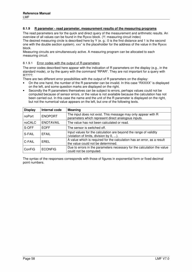
Reference Manual LMF
Page 58 LMF V7.0
8.1.9 R parameter - read parameter, measurement results of the measuring programs
The read parameters are for the quick and direct query of the measurement and arithmetic results. An overview of all values can be found in the Ryxxx block. (Y: measuring circuit index) The desired measuring circle is described here by Y (e. g.: 0 is the first distance and 1 is the second one with the double section system). xxx” is the placeholder for the address of the value in the Ryxxx block. Measuring circuits are simultaneously active. A measuring program can be allocated to each measuring circuit.
8.1.9.1 Error codes with the output of R-parameters
The error codes described here appear with the indication of R parameters on the display (e.g., in the standard mode), or by the query with the command “RPAR“. They are not important for a query with R????. There are two different error possibilities with the output of R parameters on the display: • On the one hand, the number of the R parameter can be invalid. In this case “RXXXX” is displayed
on the left, and some question marks are displayed on the right. • Secondly the R parameters themselves can be subject to errors, perhaps values could not be
computed because of sensor errors, or the value is not available because the calculation has not been carried out. In this case the name and the unit of the R parameter is displayed on the right, but not the numerical value appears on the left, but one of the following texts.
Display Internal code Meaning
noPort ENOPORT The input does not exist. This message may only appear with R parameters which represent direct analogous inputs.
noCALC ENOTAVAIL The value has not been calculated or read.
S-OFF EOFF The sensor is switched off.
S-FAIL EFAIL Input values for the calculation are beyond the range of validity (violation of limits, division by 0, ...).
C-FAIL EREL A value which is required for the calculation has an error, as a result the value could not be determined.
ConFiG ECONFIG Due to errors in the parameters necessary for the calculation the value could not be computed.
The syntax of the responses corresponds with those of figures in exponential form or fixed decimal point numbers.
Reference Manual LMF
LMF V7.0 Page 59
8.1.10 S parameter – system parameter
In the system parameter range all basic and general settings and configurations are determined. It is structured as follows: S0000 block: general parameters S0350 block: Error conditions of inputs and outputs S0500 block: User administration S1000 block: Preselection of program S1100 block: Stabilization periods nullification S1200 block: Flip-flops (flags) S1300 block: Virtual outputs S1400 block: PLC control inputs S1500 block: Input and output allocations S1600 block: Impulse valves S1800 block: Digital outputs S2000 block: Linearization of sensors S3000 block: Linearization of sensors S4000 block: Linearization of primary elements S5000 block: Linearization of primary elements S6000 block: Linearization of primary elements S7000 block: Linearization of primary elements S8000 block: Scaling of analogue outputs S9000 block: Possible special functions: S9300 block: Protocol printout S9500 block: Definition of connection for virtual outputs S9600 block: Configuration AK interface S9700 block: Process control S9800 block: Script code The behaviour of the serial interface RS 232, the sensor element and primary element linearization data as well as special functions are saved in the system parameter range. The definition of the measuring circuits and their allocation to the measuring programs serves for simultaneous supply of results for parallel running measurements and their query of results.
8.1.11 U parameter – sub programs
In this parameter field sub programs are administrated.
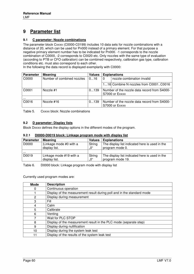
Reference Manual LMF
Page 60 LMF V7.0
9 Parameter list
9.1 C parameter: Nozzle combinations
The parameter block Cxxxx (C0000-C0199) includes 10 data sets for nozzle combinations with a distance of 20, which can be used for Pn000 instead of a primary element. For that purpose a negative primary element number has to be indicated for Pn000. -1 corresponds to the nozzle combination of C0000, -2 corresponds to C0020 etc. Only nozzles with the same type of evaluation (according to PTB or CFO calibration) can be combined respectively, calibration gas type, calibration conditions etc. must also correspond to each other. In the following the data record is displayed exemplarily with C0000: Parameter Meaning Values Explanations
C0000 Number of combined nozzles 0...16 0 nozzle combination invalid
1...16 Combine N nozzles from C0001..C0016
C0001 Nozzle #1 0...139 Number of the nozzle data record from S4000-S7000 or Exxxx
... C0016 Nozzle #16 0...139 Number of the nozzle data record from S4000-
S7000 or Exxxx
Table 5. Cxxxx block: Nozzle combinations
9.2 D parameter: Display lists
Block Dxxxx defines the display options in the different modes of the program.
9.2.1 D0000-D0019 block: Linkage program mode with display list
Parameter Meaning Values Explanations
D0000 |Linkage mode #0 with a display list.
String „0“
The display list indicated here is used in the program mode 0.
... D0019 Linkage mode #19 with a
display list. String „0“
The display list indicated here is used in the program mode 19.
Table 6. D0000 block: Linkage program mode with display list
Currently used program modes are:
Mode Description
0 Continuous operation
1 Display of the measurement result during poll and in the standard mode
2 Display during measurement
3 Fill
4 Calm
5 Calibrate
6 Venting
7 Wait for PLC STOP
8 Display of the measurement result in the PLC mode (separate step)
9 Display during nullification
10 Display during the system leak test
11 Display of the results of the system leak test
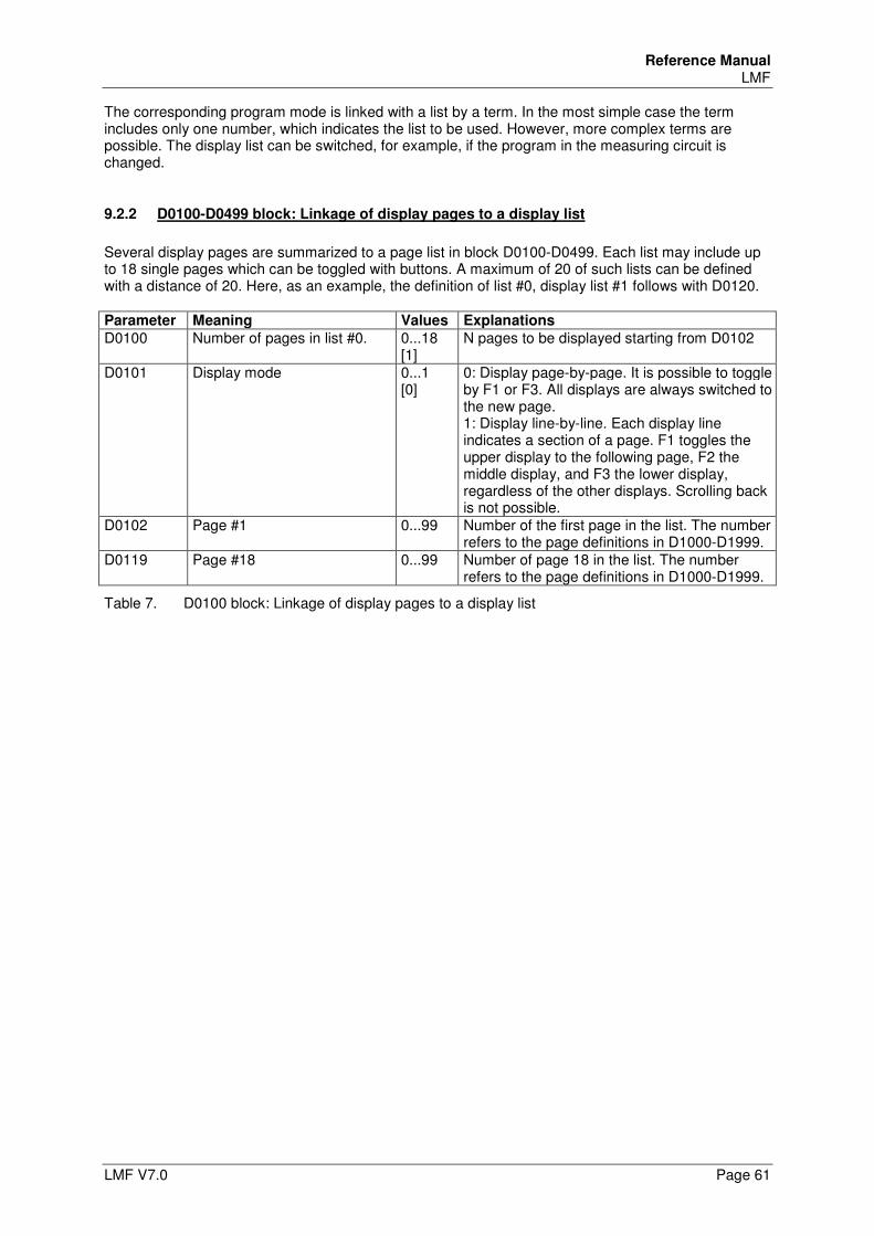
Reference Manual LMF
LMF V7.0 Page 61
The corresponding program mode is linked with a list by a term. In the most simple case the term includes only one number, which indicates the list to be used. However, more complex terms are possible. The display list can be switched, for example, if the program in the measuring circuit is changed.
9.2.2 D0100-D0499 block: Linkage of display pages to a display list
Several display pages are summarized to a page list in block D0100-D0499. Each list may include up to 18 single pages which can be toggled with buttons. A maximum of 20 of such lists can be defined with a distance of 20. Here, as an example, the definition of list #0, display list #1 follows with D0120. Parameter Meaning Values Explanations
D0100 Number of pages in list #0. 0...18 [1]
N pages to be displayed starting from D0102
D0101 Display mode 0...1 [0]
0: Display page-by-page. It is possible to toggle by F1 or F3. All displays are always switched to the new page. 1: Display line-by-line. Each display line indicates a section of a page. F1 toggles the upper display to the following page, F2 the middle display, and F3 the lower display, regardless of the other displays. Scrolling back is not possible.
D0102 Page #1 0...99 Number of the first page in the list. The number refers to the page definitions in D1000-D1999.
D0119 Page #18 0...99 Number of page 18 in the list. The number refers to the page definitions in D1000-D1999.
Table 7. D0100 block: Linkage of display pages to a display list
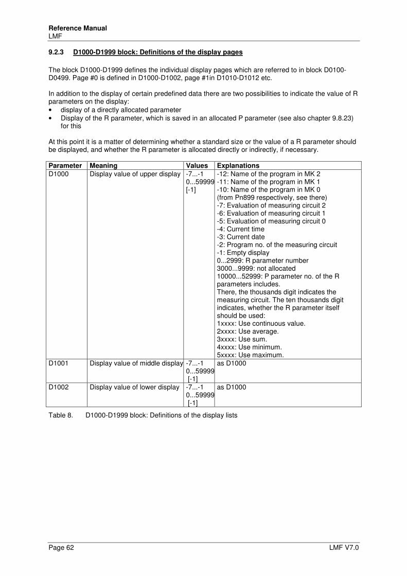
Reference Manual LMF
Page 62 LMF V7.0
9.2.3 D1000-D1999 block: Definitions of the display pages
The block D1000-D1999 defines the individual display pages which are referred to in block D0100-D0499. Page #0 is defined in D1000-D1002, page #1in D1010-D1012 etc. In addition to the display of certain predefined data there are two possibilities to indicate the value of R parameters on the display: • display of a directly allocated parameter • Display of the R parameter, which is saved in an allocated P parameter (see also chapter 9.8.23)
for this At this point it is a matter of determining whether a standard size or the value of a R parameter should be displayed, and whether the R parameter is allocated directly or indirectly, if necessary. Parameter Meaning Values Explanations
D1000 Display value of upper display -7...-1 0...59999[-1]
-12: Name of the program in MK 2 -11: Name of the program in MK 1 -10: Name of the program in MK 0 (from Pn899 respectively, see there) -7: Evaluation of measuring circuit 2 -6: Evaluation of measuring circuit 1 -5: Evaluation of measuring circuit 0 -4: Current time -3: Current date -2: Program no. of the measuring circuit -1: Empty display 0...2999: R parameter number 3000...9999: not allocated 10000...52999: P parameter no. of the R parameters includes. There, the thousands digit indicates the measuring circuit. The ten thousands digit indicates, whether the R parameter itself should be used: 1xxxx: Use continuous value. 2xxxx: Use average. 3xxxx: Use sum. 4xxxx: Use minimum. 5xxxx: Use maximum.
D1001 Display value of middle display -7...-1 0...59999 [-1]
as D1000
D1002 Display value of lower display -7...-1 0...59999 [-1]
as D1000
Table 8. D1000-D1999 block: Definitions of the display lists
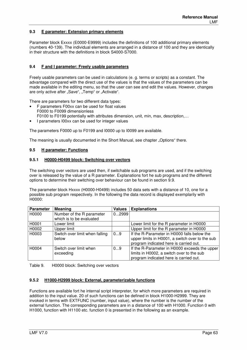
Reference Manual LMF
LMF V7.0 Page 63
9.3 E parameter: Extension primary elements
Parameter block Exxxx (E0000-E9999) includes the definitions of 100 additional primary elements (numbers 40-139). The individual elements are arranged in a distance of 100 and they are identically in their structure with the definitions in block S4000-S7000.
9.4 F and I parameter: Freely usable parameters
Freely usable parameters can be used in calculations (e. g. terms or scripts) as a constant. The advantage compared with the direct use of the values is that the values of the parameters can be made available in the editing menu, so that the user can see and edit the values. However, changes are only active after „Save“, „Temp“ or „Activate“. There are parameters for two different data types: • F parameters F00xx can be used for float values
F0000 to F0099 dimensionless F0100 to F0199 potentially with attributes dimension, unit, min, max, description,…
• I parameters I00xx can be used for integer values The parameters F0000 up to F0199 and I0000 up to I0099 are available. The meaning is usually documented in the Short Manual, see chapter „Options“ there.
9.5 H parameter: Functions
9.5.1 H0000-H0499 block: Switching over vectors
The switching over vectors are used then, if switchable sub programs are used, and if the switching over is released by the value of a R parameter. Explanations fort he sub programs and the different options to determine their switching over behaviour can be found in section 9.9. The parameter block Hxxxx (H0000-H0499) includes 50 data sets with a distance of 10, one for a possible sub program respectively. In the following the data record is displayed exemplarily with H0000: Parameter Meaning Values Explanations
H0000 Number of the R parameter which is to be evaluated
0...2999
H0001 Lower limit Lower limit for the R parameter in H0000 H0002 Upper limit Upper limit for the R parameter in H0000 H0003 Switch over limit when falling
below 0...9 If the R-Parameter in H0000 falls below the
upper limits in H0001, a switch over to the sub program indicated here is carried out.
H0004 Switch over limit when exceeding
0...9 If the R-Parameter in H0000 exceeds the upper limits in H0002, a switch over to the sub program indicated here is carried out.
Table 9. H0000 block: Switching over vectors
9.5.2 H1000-H2999 block: External, parameterizable functions
Functions are available fort he internal script interpreter, for which more parameters are required in addition to the input value. 20 of such functions can be defined in block H1000-H2999. They are invoked in terms with EXTFUNC (number, input value), where the number is the number of the external function. The corresponding parameters are in a distance of 100 with H1000. Function 0 with H1000, function with H1100 etc. function 0 is presented in the following as an example.
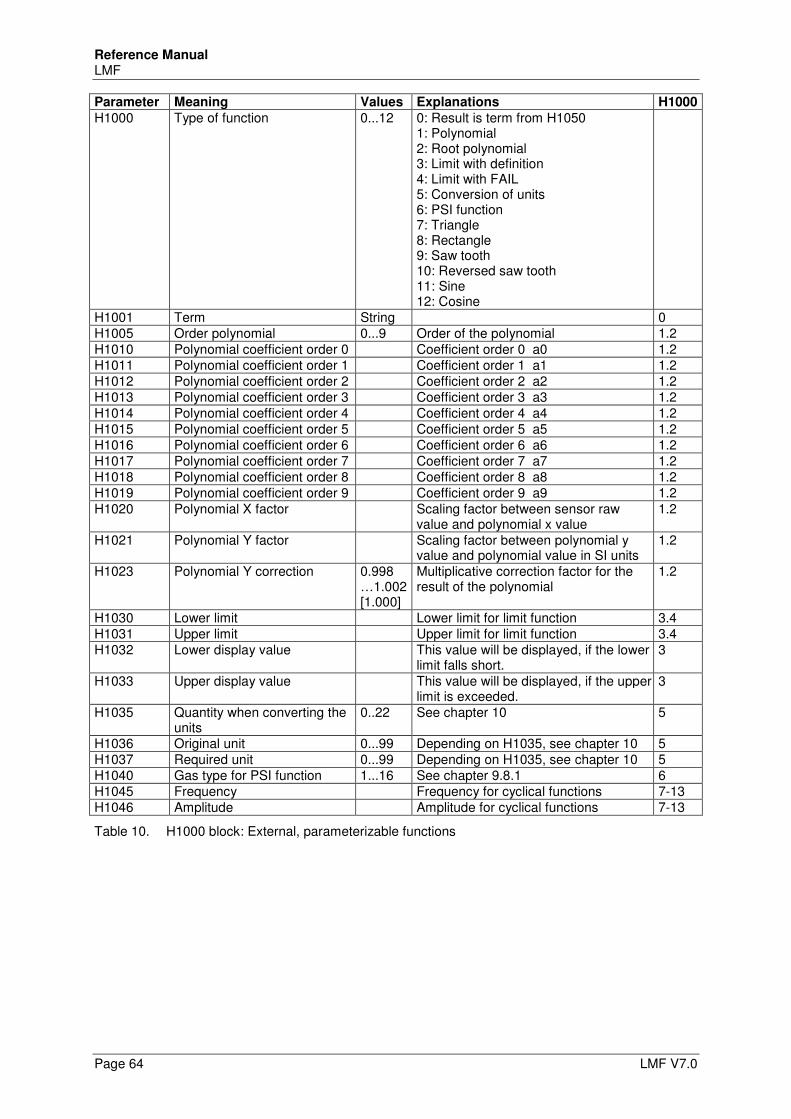
Reference Manual LMF
Page 64 LMF V7.0
Parameter Meaning Values Explanations H1000
H1000 Type of function 0...12 0: Result is term from H1050 1: Polynomial 2: Root polynomial 3: Limit with definition 4: Limit with FAIL 5: Conversion of units 6: PSI function 7: Triangle 8: Rectangle 9: Saw tooth 10: Reversed saw tooth 11: Sine 12: Cosine
H1001 Term String 0 H1005 Order polynomial 0...9 Order of the polynomial 1.2 H1010 Polynomial coefficient order 0 Coefficient order 0 a0 1.2 H1011 Polynomial coefficient order 1 Coefficient order 1 a1 1.2 H1012 Polynomial coefficient order 2 Coefficient order 2 a2 1.2 H1013 Polynomial coefficient order 3 Coefficient order 3 a3 1.2 H1014 Polynomial coefficient order 4 Coefficient order 4 a4 1.2 H1015 Polynomial coefficient order 5 Coefficient order 5 a5 1.2 H1016 Polynomial coefficient order 6 Coefficient order 6 a6 1.2 H1017 Polynomial coefficient order 7 Coefficient order 7 a7 1.2 H1018 Polynomial coefficient order 8 Coefficient order 8 a8 1.2 H1019 Polynomial coefficient order 9 Coefficient order 9 a9 1.2 H1020 Polynomial X factor Scaling factor between sensor raw
value and polynomial x value 1.2
H1021 Polynomial Y factor Scaling factor between polynomial y value and polynomial value in SI units
1.2
H1023 Polynomial Y correction 0.998 …1.002 [1.000]
Multiplicative correction factor for the result of the polynomial
1.2
H1030 Lower limit Lower limit for limit function 3.4 H1031 Upper limit Upper limit for limit function 3.4 H1032 Lower display value This value will be displayed, if the lower
limit falls short. 3
H1033 Upper display value This value will be displayed, if the upper limit is exceeded.
3
H1035 Quantity when converting the units
0..22 See chapter 10 5
H1036 Original unit 0...99 Depending on H1035, see chapter 10 5 H1037 Required unit 0...99 Depending on H1035, see chapter 10 5 H1040 Gas type for PSI function 1...16 See chapter 9.8.1 6 H1045 Frequency Frequency for cyclical functions 7-13 H1046 Amplitude Amplitude for cyclical functions 7-13
Table 10. H1000 block: External, parameterizable functions
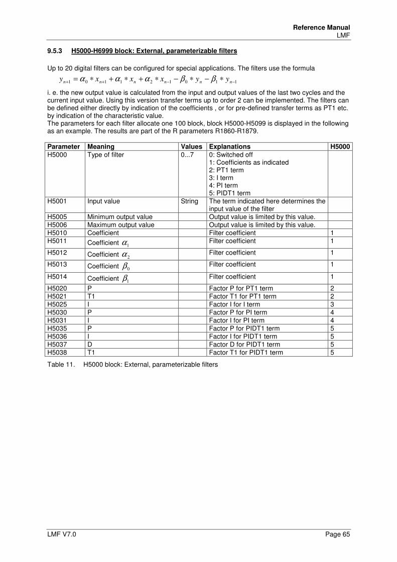
Reference Manual LMF
LMF V7.0 Page 65
9.5.3 H5000-H6999 block: External, parameterizable filters
Up to 20 digital filters can be configured for special applications. The filters use the formula
110121101 −−++ ∗−∗−∗+∗+∗= nnnnnn yyxxxy ββααα
i. e. the new output value is calculated from the input and output values of the last two cycles and the current input value. Using this version transfer terms up to order 2 can be implemented. The filters can be defined either directly by indication of the coefficients , or for pre-defined transfer terms as PT1 etc. by indication of the characteristic value. The parameters for each filter allocate one 100 block, block H5000-H5099 is displayed in the following as an example. The results are part of the R parameters R1860-R1879. Parameter Meaning Values Explanations H5000
H5000 Type of filter 0...7 0: Switched off 1: Coefficients as indicated 2: PT1 term 3: I term 4: PI term 5: PIDT1 term
H5001 Input value String The term indicated here determines the input value of the filter
H5005 Minimum output value Output value is limited by this value. H5006 Maximum output value Output value is limited by this value. H5010 Coefficient Filter coefficient 1 H5011 Coefficient 1α Filter coefficient 1
H5012 Coefficient 2α Filter coefficient 1
H5013 Coefficient 0β Filter coefficient 1
H5014 Coefficient 1β Filter coefficient 1
H5020 P Factor P for PT1 term 2 H5021 T1 Factor T1 for PT1 term 2 H5025 I Factor I for I term 3 H5030 P Factor P for PI term 4 H5031 I Factor I for PI term 4 H5035 P Factor P for PIDT1 term 5 H5036 I Factor I for PIDT1 term 5 H5037 D Factor D for PIDT1 term 5 H5038 T1 Factor T1 for PIDT1 term 5
Table 11. H5000 block: External, parameterizable filters
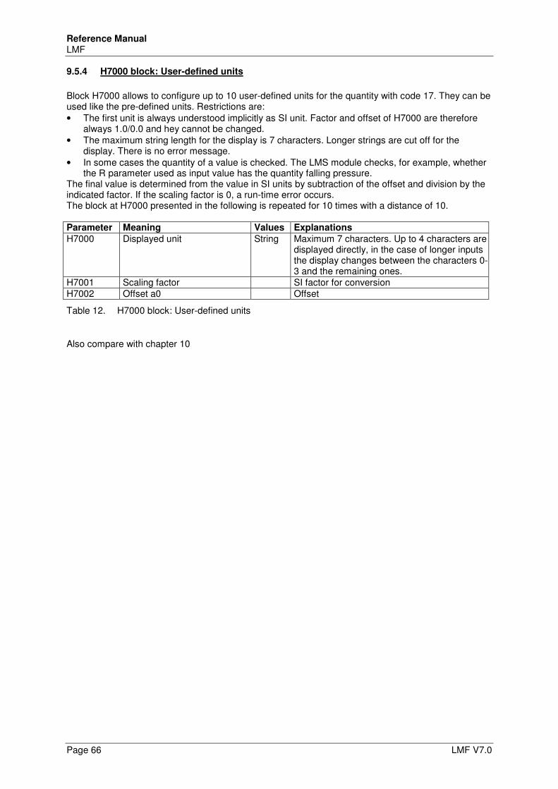
Reference Manual LMF
Page 66 LMF V7.0
9.5.4 H7000 block: User-defined units
Block H7000 allows to configure up to 10 user-defined units for the quantity with code 17. They can be used like the pre-defined units. Restrictions are: • The first unit is always understood implicitly as SI unit. Factor and offset of H7000 are therefore
always 1.0/0.0 and hey cannot be changed. • The maximum string length for the display is 7 characters. Longer strings are cut off for the
display. There is no error message. • In some cases the quantity of a value is checked. The LMS module checks, for example, whether
the R parameter used as input value has the quantity falling pressure. The final value is determined from the value in SI units by subtraction of the offset and division by the indicated factor. If the scaling factor is 0, a run-time error occurs. The block at H7000 presented in the following is repeated for 10 times with a distance of 10. Parameter Meaning Values Explanations
H7000 Displayed unit String Maximum 7 characters. Up to 4 characters are displayed directly, in the case of longer inputs the display changes between the characters 0-3 and the remaining ones.
H7001 Scaling factor SI factor for conversion H7002 Offset a0 Offset
Table 12. H7000 block: User-defined units
Also compare with chapter 10
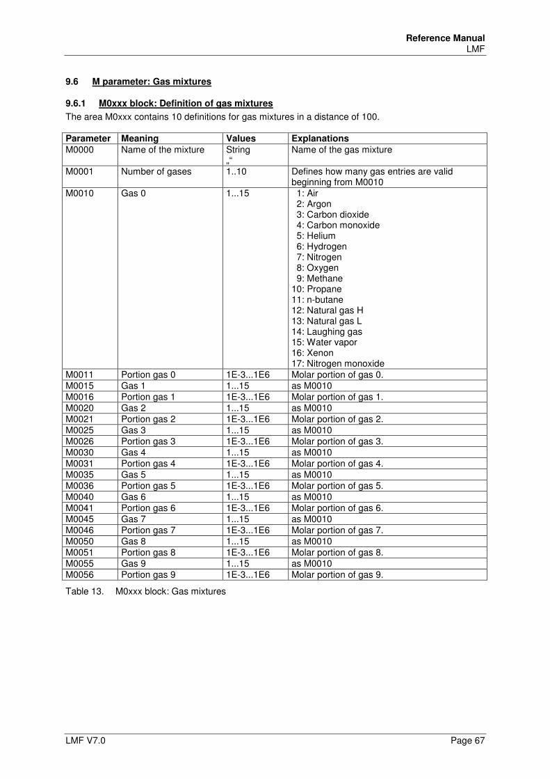
Reference Manual LMF
LMF V7.0 Page 67
9.6 M parameter: Gas mixtures
9.6.1 M0xxx block: Definition of gas mixtures
The area M0xxx contains 10 definitions for gas mixtures in a distance of 100. Parameter Meaning Values Explanations
M0000 Name of the mixture String „“
Name of the gas mixture
M0001 Number of gases 1..10 Defines how many gas entries are valid beginning from M0010
M0010 Gas 0 1...15 1: Air 2: Argon 3: Carbon dioxide 4: Carbon monoxide 5: Helium 6: Hydrogen 7: Nitrogen 8: Oxygen 9: Methane 10: Propane 11: n-butane 12: Natural gas H 13: Natural gas L 14: Laughing gas 15: Water vapor 16: Xenon 17: Nitrogen monoxide
M0011 Portion gas 0 1E-3...1E6 Molar portion of gas 0. M0015 Gas 1 1...15 as M0010 M0016 Portion gas 1 1E-3...1E6 Molar portion of gas 1. M0020 Gas 2 1...15 as M0010 M0021 Portion gas 2 1E-3...1E6 Molar portion of gas 2. M0025 Gas 3 1...15 as M0010 M0026 Portion gas 3 1E-3...1E6 Molar portion of gas 3. M0030 Gas 4 1...15 as M0010 M0031 Portion gas 4 1E-3...1E6 Molar portion of gas 4. M0035 Gas 5 1...15 as M0010 M0036 Portion gas 5 1E-3...1E6 Molar portion of gas 5. M0040 Gas 6 1...15 as M0010 M0041 Portion gas 6 1E-3...1E6 Molar portion of gas 6. M0045 Gas 7 1...15 as M0010 M0046 Portion gas 7 1E-3...1E6 Molar portion of gas 7. M0050 Gas 8 1...15 as M0010 M0051 Portion gas 8 1E-3...1E6 Molar portion of gas 8. M0055 Gas 9 1...15 as M0010 M0056 Portion gas 9 1E-3...1E6 Molar portion of gas 9.
Table 13. M0xxx block: Gas mixtures
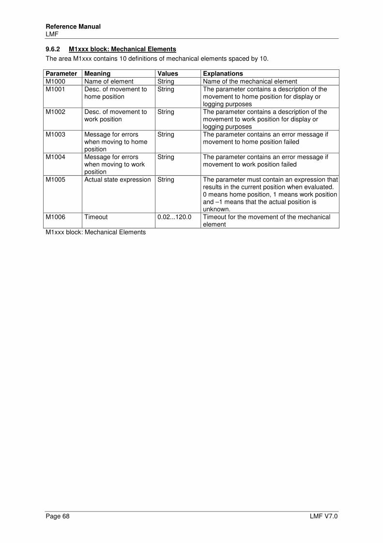
Reference Manual LMF
Page 68 LMF V7.0
9.6.2 M1xxx block: Mechanical Elements
The area M1xxx contains 10 definitions of mechanical elements spaced by 10. Parameter Meaning Values Explanations
M1000 Name of element String Name of the mechanical element M1001 Desc. of movement to
home position String The parameter contains a description of the
movement to home position for display or logging purposes
M1002 Desc. of movement to work position
String The parameter contains a description of the movement to work position for display or logging purposes
M1003 Message for errors when moving to home position
String The parameter contains an error message if movement to home position failed
M1004 Message for errors when moving to work position
String The parameter contains an error message if movement to work position failed
M1005 Actual state expression String The parameter must contain an expression that results in the current position when evaluated. 0 means home position, 1 means work position and –1 means that the actual position is unknown.
M1006 Timeout 0.02...120.0 Timeout for the movement of the mechanical element
M1xxx block: Mechanical Elements
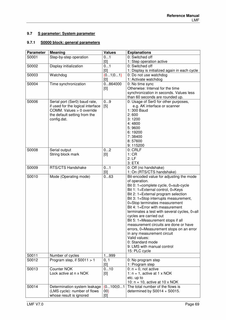
Reference Manual LMF
LMF V7.0 Page 69
9.7 S parameter: System parameter
9.7.1 S0000 block: general parameters
Parameter Meaning Values Explanations
S0001 Step-by-step operation 0...1 [0]
0: Switched off 1: Step operation active
S0002 Display initialization 0...1 [0]
0: Switched off 1: Display is initialized again in each cycle
S0003 Watchdog {0...1|0...1} [0]
0: Do not use watchdog 1: Activate watchdog
S0004 Time synchronization 0...864000 [0]
0: No time sync Otherwise: Interval for the time synchronization in seconds. Values less than 60 seconds are rounded up.
S0006 Serial port (Ser0) baud rate, if used for the logical interface COMM. Values > 0 override the default setting from the config.dat.
0...9 [5]
0: Usage of Ser0 for other purposes, e.g. AK interface or scanner 1: 300 Baud 2: 600 3: 1200 4: 4800 5: 9600 6: 19200 7: 38400 8: 57600 9: 115200
S0008 Serial output String block mark
0...2 [0]
0: CRLF 1: CR 2: LF 3: ETX
S0009 RTS/CTS Handshake 0...1 [0]
0: Off (no handshake) 1: On (RTS/CTS handshake)
S0010 Mode (Operating mode) 0...63 Bit-encoded value for adjusting the mode of operation. Bit 0: 1=complete cycle, 0=sub-cycle Bit 1: 1=External control, 0=Keys Bit 2: 1=External program selection Bit 3: 1=Stop interrupts measurement, 0=Stop terminates measurement Bit 4: 1=Error with measurement terminates a test with several cycles, 0=all cycles are carried out Bit 5: 1=Measurement stops if all measurement circuits are done or have errors, 0=Measurement stops on an error in any measurement circuit Valid values: 0: Standard mode 9: LMS with manual control 15: PLC cycle
S0011 Number of cycles 1...999 S0012 Program step, if S0011 > 1 0, 1
[0] 0: No program step 1: Program step
S0013 Counter NOK Lock active at n x NOK
0...10 [0]
0: n = 0, not active 1: n = 1, active at 1 x NOK etc. up to 10: n = 10, active at 10 x NOK
S0014 Determination system leakage (LMS cycle): number of flows whose result is ignored
{0...100|0...100} [0]
The total number of the flows is determined by S0014 + S0015.
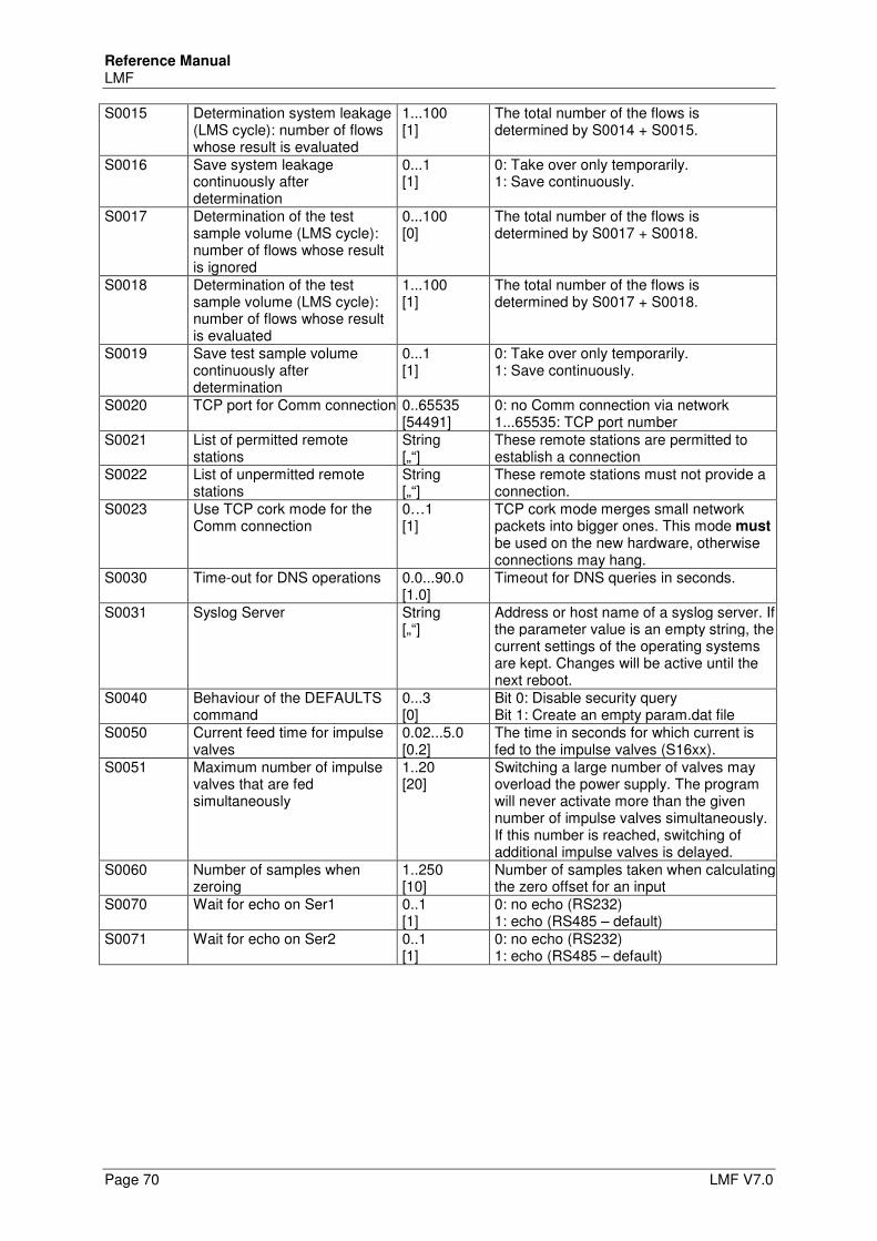
Reference Manual LMF
Page 70 LMF V7.0
S0015 Determination system leakage (LMS cycle): number of flows whose result is evaluated
1...100 [1]
The total number of the flows is determined by S0014 + S0015.
S0016 Save system leakage continuously after determination
0...1 [1]
0: Take over only temporarily. 1: Save continuously.
S0017 Determination of the test sample volume (LMS cycle): number of flows whose result is ignored
0...100 [0]
The total number of the flows is determined by S0017 + S0018.
S0018 Determination of the test sample volume (LMS cycle): number of flows whose result is evaluated
1...100 [1]
The total number of the flows is determined by S0017 + S0018.
S0019 Save test sample volume continuously after determination
0...1 [1]
0: Take over only temporarily. 1: Save continuously.
S0020 TCP port for Comm connection 0..65535 [54491]
0: no Comm connection via network 1...65535: TCP port number
S0021 List of permitted remote stations
String [„“]
These remote stations are permitted to establish a connection
S0022 List of unpermitted remote stations
String [„“]
These remote stations must not provide a connection.
S0023 Use TCP cork mode for the Comm connection
0…1 [1]
TCP cork mode merges small network packets into bigger ones. This mode must be used on the new hardware, otherwise connections may hang.
S0030 Time-out for DNS operations 0.0...90.0 [1.0]
Timeout for DNS queries in seconds.
S0031 Syslog Server String [„“]
Address or host name of a syslog server. If the parameter value is an empty string, the current settings of the operating systems are kept. Changes will be active until the next reboot.
S0040 Behaviour of the DEFAULTS command
0...3 [0]
Bit 0: Disable security query Bit 1: Create an empty param.dat file
S0050 Current feed time for impulse valves
0.02...5.0 [0.2]
The time in seconds for which current is fed to the impulse valves (S16xx).
S0051 Maximum number of impulse valves that are fed simultaneously
1..20 [20]
Switching a large number of valves may overload the power supply. The program will never activate more than the given number of impulse valves simultaneously. If this number is reached, switching of additional impulse valves is delayed.
S0060 Number of samples when zeroing
1..250 [10]
Number of samples taken when calculating the zero offset for an input
S0070 Wait for echo on Ser1 0..1 [1]
0: no echo (RS232) 1: echo (RS485 – default)
S0071 Wait for echo on Ser2 0..1 [1]
0: no echo (RS232) 1: echo (RS485 – default)
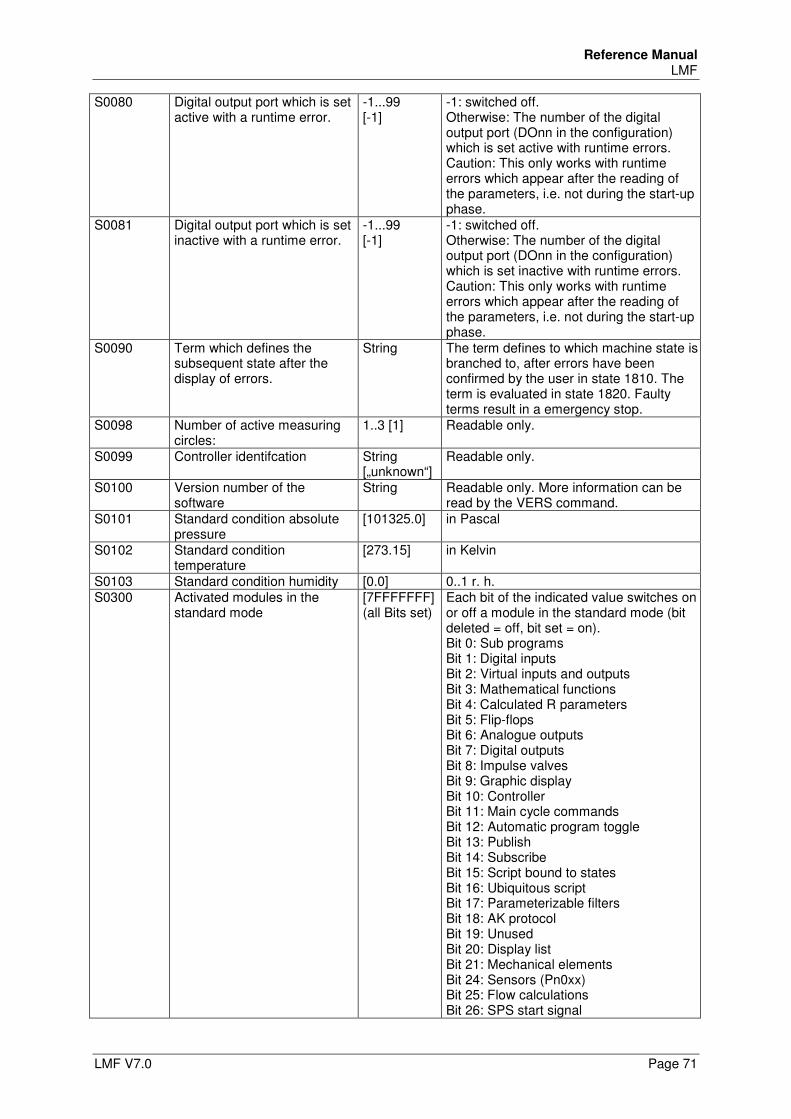
Reference Manual LMF
LMF V7.0 Page 71
S0080 Digital output port which is set active with a runtime error.
-1...99 [-1]
-1: switched off. Otherwise: The number of the digital output port (DOnn in the configuration) which is set active with runtime errors. Caution: This only works with runtime errors which appear after the reading of the parameters, i.e. not during the start-up phase.
S0081 Digital output port which is set inactive with a runtime error.
-1...99 [-1]
-1: switched off. Otherwise: The number of the digital output port (DOnn in the configuration) which is set inactive with runtime errors. Caution: This only works with runtime errors which appear after the reading of the parameters, i.e. not during the start-up phase.
S0090 Term which defines the subsequent state after the display of errors.
String
The term defines to which machine state is branched to, after errors have been confirmed by the user in state 1810. The term is evaluated in state 1820. Faulty terms result in a emergency stop.
S0098 Number of active measuring circles:
1..3 [1] Readable only.
S0099 Controller identifcation String [„unknown“]
Readable only.
S0100 Version number of the software
String Readable only. More information can be read by the VERS command.
S0101 Standard condition absolute pressure
[101325.0] in Pascal
S0102 Standard condition temperature
[273.15] in Kelvin
S0103 Standard condition humidity [0.0] 0..1 r. h. S0300 Activated modules in the
standard mode [7FFFFFFF] (all Bits set)
Each bit of the indicated value switches on or off a module in the standard mode (bit deleted = off, bit set = on). Bit 0: Sub programs Bit 1: Digital inputs Bit 2: Virtual inputs and outputs Bit 3: Mathematical functions Bit 4: Calculated R parameters Bit 5: Flip-flops Bit 6: Analogue outputs Bit 7: Digital outputs Bit 8: Impulse valves Bit 9: Graphic display Bit 10: Controller Bit 11: Main cycle commands Bit 12: Automatic program toggle Bit 13: Publish Bit 14: Subscribe Bit 15: Script bound to states Bit 16: Ubiquitous script Bit 17: Parameterizable filters Bit 18: AK protocol Bit 19: Unused Bit 20: Display list Bit 21: Mechanical elements Bit 24: Sensors (Pn0xx) Bit 25: Flow calculations Bit 26: SPS start signal
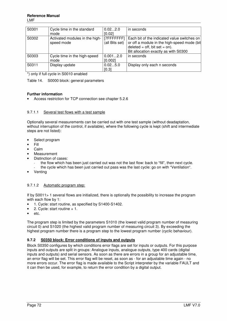
Reference Manual LMF
Page 72 LMF V7.0
S0301 Cycle time in the standard mode
0.02...2.0 [0.02]
in seconds
S0302 Activated modules in the high-speed mode
[7FFFFFFF] (all Bits set)
Each bit of the indicated value switches on or off a module in the high-speed mode (bit deleted = off, bit set = on). Bit allocation exactly as with S0300
S0303 Cycle time in the high-speed mode
0.001...2.0 [0.002]
in seconds
S0311 Display update 0.02...5.0 [0.3]
Display only each n seconds
*) only if full cycle in S0010 enabled
Table 14. S0000 block: general parameters
Further information
• Access restriction for TCP connection see chapter 5.2.6
9.7.1.1 Several test flows with a test sample
Optionally several measurements can be carried out with one test sample (without deadaptation, without interruption of the control, if available), where the following cycle is kept (shift and intermediate steps are not listed): • Select program • Fill • Calm • Measurement • Distinction of cases:
- the flow which has been just carried out was not the last flow: back to “fill”, then next cycle. - the cycle which has been just carried out pass was the last cycle: go on with “Ventilation“.
• Venting
9.7.1.2 Automatic program step:
If by S0011> 1 several flows are initialized, there is optionally the possibility to increase the program with each flow by 1: • 1. Cycle: start routine, as specified by S1400-S1402. • 2. Cycle: start routine + 1. • etc. The program step is limited by the parameters S1010 (the lowest valid program number of measuring circuit 0) and S1020 (the highest valid program number of measuring circuit 3). By exceeding the highest program number there is a program step to the lowest program number (cyclic behaviour).
9.7.2 S0350 block: Error conditions of inputs and outputs
Block S0350 configures by which conditions error flags are set for inputs or outputs. For this purpose inputs and outputs are split in groups: Analogue inputs, analogue outputs, type 400 cards (digital inputs and outputs) and serial sensors. As soon as there are errors in a group for an adjustable time, an error flag will be set. This error flag will be reset, as soon as - for an adjustable time again - no more errors occur. The error flag is made available to the Script interpreter by the variable FAULT and it can then be used, for example, to return the error condition by a digital output.
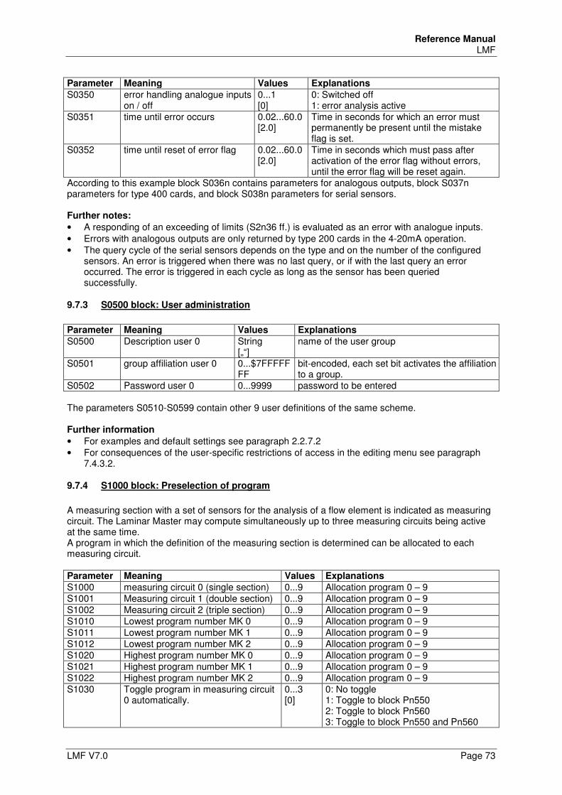
Reference Manual LMF
LMF V7.0 Page 73
Parameter Meaning Values Explanations
S0350 error handling analogue inputs on / off
0...1 [0]
0: Switched off 1: error analysis active
S0351 time until error occurs 0.02...60.0 [2.0]
Time in seconds for which an error must permanently be present until the mistake flag is set.
S0352 time until reset of error flag 0.02...60.0 [2.0]
Time in seconds which must pass after activation of the error flag without errors, until the error flag will be reset again.
According to this example block S036n contains parameters for analogous outputs, block S037n parameters for type 400 cards, and block S038n parameters for serial sensors. Further notes:
• A responding of an exceeding of limits (S2n36 ff.) is evaluated as an error with analogue inputs. • Errors with analogous outputs are only returned by type 200 cards in the 4-20mA operation. • The query cycle of the serial sensors depends on the type and on the number of the configured
sensors. An error is triggered when there was no last query, or if with the last query an error occurred. The error is triggered in each cycle as long as the sensor has been queried successfully.
9.7.3 S0500 block: User administration
Parameter Meaning Values Explanations
S0500 Description user 0 String [„“]
name of the user group
S0501 group affiliation user 0 0...$7FFFFFFF
bit-encoded, each set bit activates the affiliation to a group.
S0502 Password user 0 0...9999 password to be entered The parameters S0510-S0599 contain other 9 user definitions of the same scheme. Further information
• For examples and default settings see paragraph 2.2.7.2 • For consequences of the user-specific restrictions of access in the editing menu see paragraph
7.4.3.2.
9.7.4 S1000 block: Preselection of program
A measuring section with a set of sensors for the analysis of a flow element is indicated as measuring circuit. The Laminar Master may compute simultaneously up to three measuring circuits being active at the same time. A program in which the definition of the measuring section is determined can be allocated to each measuring circuit. Parameter Meaning Values Explanations
S1000 measuring circuit 0 (single section) 0...9 Allocation program 0 – 9 S1001 Measuring circuit 1 (double section) 0...9 Allocation program 0 – 9 S1002 Measuring circuit 2 (triple section) 0...9 Allocation program 0 – 9 S1010 Lowest program number MK 0 0...9 Allocation program 0 – 9 S1011 Lowest program number MK 1 0...9 Allocation program 0 – 9 S1012 Lowest program number MK 2 0...9 Allocation program 0 – 9 S1020 Highest program number MK 0 0...9 Allocation program 0 – 9 S1021 Highest program number MK 1 0...9 Allocation program 0 – 9 S1022 Highest program number MK 2 0...9 Allocation program 0 – 9 S1030 Toggle program in measuring circuit
0 automatically. 0...3 [0]
0: No toggle 1: Toggle to block Pn550 2: Toggle to block Pn560 3: Toggle to block Pn550 and Pn560
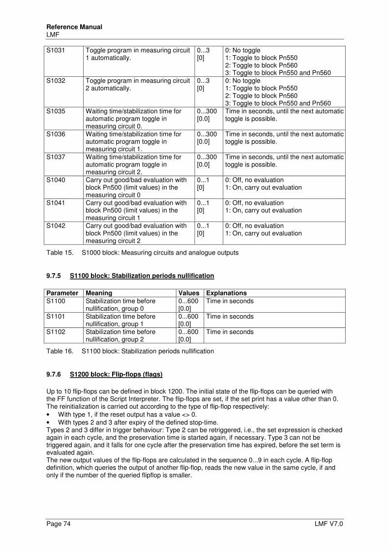
Reference Manual LMF
Page 74 LMF V7.0
S1031 Toggle program in measuring circuit 1 automatically.
0...3 [0]
0: No toggle 1: Toggle to block Pn550 2: Toggle to block Pn560 3: Toggle to block Pn550 and Pn560
S1032 Toggle program in measuring circuit 2 automatically.
0...3 [0]
0: No toggle 1: Toggle to block Pn550 2: Toggle to block Pn560 3: Toggle to block Pn550 and Pn560
S1035 Waiting time/stabilization time for automatic program toggle in measuring circuit 0.
0...300 [0.0]
Time in seconds, until the next automatic toggle is possible.
S1036 Waiting time/stabilization time for automatic program toggle in measuring circuit 1.
0...300 [0.0]
Time in seconds, until the next automatic toggle is possible.
S1037 Waiting time/stabilization time for automatic program toggle in measuring circuit 2.
0...300 [0.0]
Time in seconds, until the next automatic toggle is possible.
S1040 Carry out good/bad evaluation with block Pn500 (limit values) in the measuring circuit 0
0...1 [0]
0: Off, no evaluation 1: On, carry out evaluation
S1041 Carry out good/bad evaluation with block Pn500 (limit values) in the measuring circuit 1
0...1 [0]
0: Off, no evaluation 1: On, carry out evaluation
S1042 Carry out good/bad evaluation with block Pn500 (limit values) in the measuring circuit 2
0...1 [0]
0: Off, no evaluation 1: On, carry out evaluation
Table 15. S1000 block: Measuring circuits and analogue outputs
9.7.5 S1100 block: Stabilization periods nullification
Parameter Meaning Values Explanations
S1100 Stabilization time before nullification, group 0
0...600 [0.0]
Time in seconds
S1101 Stabilization time before nullification, group 1
0...600 [0.0]
Time in seconds
S1102 Stabilization time before nullification, group 2
0...600 [0.0]
Time in seconds
Table 16. S1100 block: Stabilization periods nullification
9.7.6 S1200 block: Flip-flops (flags)
Up to 10 flip-flops can be defined in block 1200. The initial state of the flip-flops can be queried with the FF function of the Script Interpreter. The flip-flops are set, if the set print has a value other than 0. The reinitialization is carried out according to the type of flip-flop respectively: • With type 1, if the reset output has a value <> 0. • With types 2 and 3 after expiry of the defined stop-time. Types 2 and 3 differ in trigger behaviour: Type 2 can be retriggered, i.e., the set expression is checked again in each cycle, and the preservation time is started again, if necessary. Type 3 can not be triggered again, and it falls for one cycle after the preservation time has expired, before the set term is evaluated again. The new output values of the flip-flops are calculated in the sequence 0...9 in each cycle. A flip-flop definition, which queries the output of another flip-flop, reads the new value in the same cycle, if and only if the number of the queried flipflop is smaller.
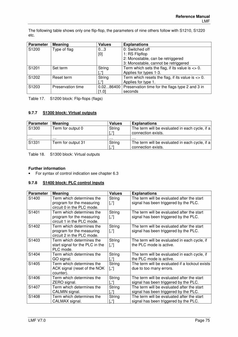
Reference Manual LMF
LMF V7.0 Page 75
The following table shows only one flip-flop, the parameters of nine others follow with S1210, S1220 etc. Parameter Meaning Values Explanations
S1200 Type of flag 0...3 [0]
0: Switched off 1: RS Flipflop 2: Monostable, can be retriggered 3: Monostable, cannot be retriggered
S1201 Set term String [„“]
Term which sets the flag, if its value is <> 0. Applies for types 1-3.
S1202 Reset term String [„“]
Term which resets the flag, if its value is <> 0. Applies for type 1.
S1203 Preservation time 0.02...86400 [1.0]
Preservation time for the flags type 2 and 3 in seconds
Table 17. S1200 block: Flip-flops (flags)
9.7.7 S1300 block: Virtual outputs
Parameter Meaning Values Explanations
S1300 Term for output 0 String [„“]
The term will be evaluated in each cycle, if a connection exists.
… … … … S1331 Term for output 31 String
[„“] The term will be evaluated in each cycle, if a connection exists.
Table 18. S1300 block: Virtual outputs
Further information
• For syntax of control indication see chapter 6.3
9.7.8 S1400 block: PLC control inputs
Parameter Meaning Values Explanations
S1400 Term which determines the program for the measuring circuit 0 in the PLC mode.
String [„“]
The term will be evaluated after the start signal has been triggered by the PLC.
S1401 Term which determines the program for the measuring circuit 1 in the PLC mode.
String [„“]
The term will be evaluated after the start signal has been triggered by the PLC.
S1402 Term which determines the program for the measuring circuit 2 in the PLC mode.
String [„“]
The term will be evaluated after the start signal has been triggered by the PLC.
S1403 Term which determines the start signal for the PLC in the PLC mode.
String [„“]
The term will be evaluated in each cycle, if the PLC mode is active.
S1404 Term which determines the GO signal.
String [„“]
The term will be evaluated in each cycle, if the PLC mode is active.
S1405 Term which determines the ACK signal (reset of the NOK counter).
String [„“]
The term will be evaluated if a lockout exists due to too many errors.
S1406 Term which determines the ZERO signal.
String [„“]
The term will be evaluated after the start signal has been triggered by the PLC.
S1407 Term which determines the CALMIN signal.
String [„“]
The term will be evaluated after the start signal has been triggered by the PLC.
S1408 Term which determines the CALMAX signal.
String [„“]
The term will be evaluated after the start signal has been triggered by the PLC.
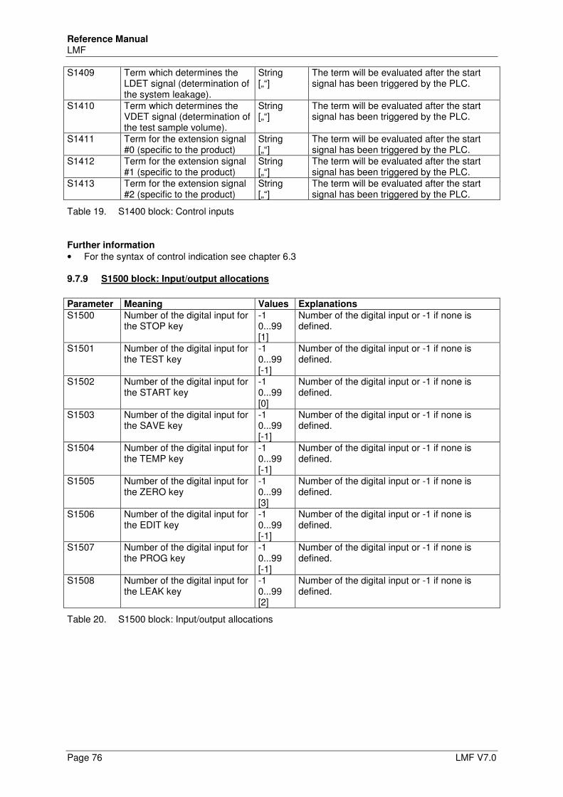
Reference Manual LMF
Page 76 LMF V7.0
S1409 Term which determines the LDET signal (determination of the system leakage).
String [„“]
The term will be evaluated after the start signal has been triggered by the PLC.
S1410 Term which determines the VDET signal (determination of the test sample volume).
String [„“]
The term will be evaluated after the start signal has been triggered by the PLC.
S1411 Term for the extension signal #0 (specific to the product)
String [„“]
The term will be evaluated after the start signal has been triggered by the PLC.
S1412 Term for the extension signal #1 (specific to the product)
String [„“]
The term will be evaluated after the start signal has been triggered by the PLC.
S1413 Term for the extension signal #2 (specific to the product)
String [„“]
The term will be evaluated after the start signal has been triggered by the PLC.
Table 19. S1400 block: Control inputs
Further information
• For the syntax of control indication see chapter 6.3
9.7.9 S1500 block: Input/output allocations
Parameter Meaning Values Explanations
S1500 Number of the digital input for the STOP key
-1 0...99 [1]
Number of the digital input or -1 if none is defined.
S1501 Number of the digital input for the TEST key
-1 0...99 [-1]
Number of the digital input or -1 if none is defined.
S1502 Number of the digital input for the START key
-1 0...99 [0]
Number of the digital input or -1 if none is defined.
S1503 Number of the digital input for the SAVE key
-1 0...99 [-1]
Number of the digital input or -1 if none is defined.
S1504 Number of the digital input for the TEMP key
-1 0...99 [-1]
Number of the digital input or -1 if none is defined.
S1505 Number of the digital input for the ZERO key
-1 0...99 [3]
Number of the digital input or -1 if none is defined.
S1506 Number of the digital input for the EDIT key
-1 0...99 [-1]
Number of the digital input or -1 if none is defined.
S1507 Number of the digital input for the PROG key
-1 0...99 [-1]
Number of the digital input or -1 if none is defined.
S1508 Number of the digital input for the LEAK key
-1 0...99 [2]
Number of the digital input or -1 if none is defined.
Table 20. S1500 block: Input/output allocations
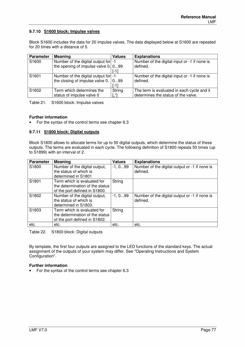
Reference Manual LMF
LMF V7.0 Page 77
9.7.10 S1600 block: Impulse valves
Block S1600 includes the data for 20 impulse valves. The data displayed below at S1600 are repeated for 20 times with a distance of 5. Parameter Meaning Values Explanations
S1600 Number of the digital output for the opening of impulse valve 0.
-1 0...99 [-1]
Number of the digital input or -1 if none is defined.
S1601 Number of the digital output for the closing of impulse valve 0.
-1 0...99 [-1]
Number of the digital input or -1 if none is defined.
S1602 Term which determines the status of impulse valve 0
String [„“]
The term is evaluated in each cycle and it determines the status of the valve.
Table 21. S1600 block: Impulse valves
Further information
• For the syntax of the control terms see chapter 6.3
9.7.11 S1800 block: Digital outputs
Block S1800 allows to allocate terms for up to 50 digital outputs, which determine the status of these outputs. The terms are evaluated in each cycle. The following definition of S1800 repeats 50 times (up to S1899) with an interval of 2. Parameter Meaning Values Explanations
S1800 Number of the digital output, the status of which is determined in S1801
-1, 0...99
Number of the digital output or -1 if none is defined.
S1801 Term which is evaluated for the determination of the status of the port defined in S1800.
String
S1802 Number of the digital output, the status of which is determined in S1803.
-1, 0...99
Number of the digital output or -1 if none is defined.
S1803 Term which is evaluated for the determination of the status of the port defined in S1802.
String
etc. etc. etc. etc.
Table 22. S1800 block: Digital outputs
By template, the first four outputs are assigned to the LED functions of the standard keys. The actual assignment of the outputs of your system may differ. See "Operating Instructions and System Configuration". Further information
• For the syntax of the control terms see chapter 6.3
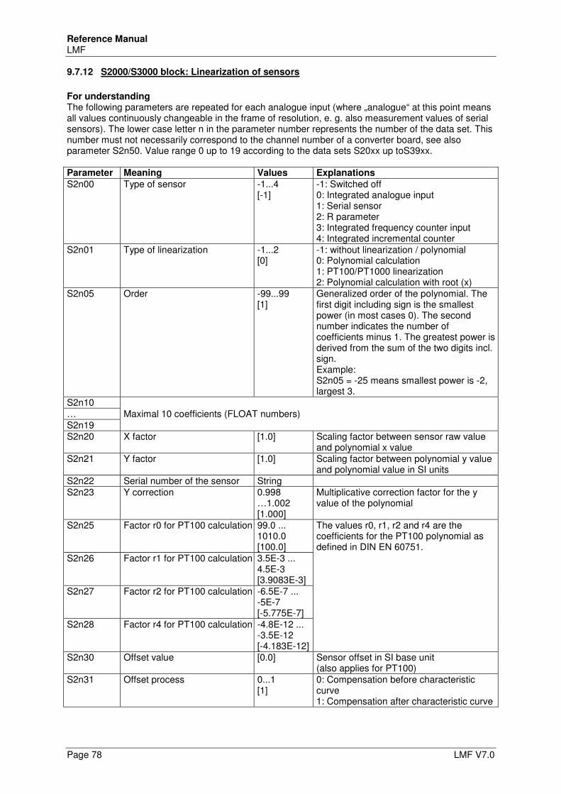
Reference Manual LMF
Page 78 LMF V7.0
9.7.12 S2000/S3000 block: Linearization of sensors
For understanding The following parameters are repeated for each analogue input (where „analogue“ at this point means all values continuously changeable in the frame of resolution, e. g. also measurement values of serial sensors). The lower case letter n in the parameter number represents the number of the data set. This number must not necessarily correspond to the channel number of a converter board, see also parameter S2n50. Value range 0 up to 19 according to the data sets S20xx up toS39xx.
Parameter Meaning Values Explanations
S2n00 Type of sensor -1...4 [-1]
-1: Switched off 0: Integrated analogue input 1: Serial sensor 2: R parameter 3: Integrated frequency counter input 4: Integrated incremental counter
S2n01 Type of linearization -1...2 [0]
-1: without linearization / polynomial 0: Polynomial calculation 1: PT100/PT1000 linearization 2: Polynomial calculation with root (x)
S2n05 Order -99...99 [1]
Generalized order of the polynomial. The first digit including sign is the smallest power (in most cases 0). The second number indicates the number of coefficients minus 1. The greatest power is derived from the sum of the two digits incl. sign. Example: S2n05 = -25 means smallest power is -2, largest 3.
S2n10 Maximal 10 coefficients (FLOAT numbers) …
S2n19 S2n20 X factor [1.0] Scaling factor between sensor raw value
and polynomial x value S2n21 Y factor [1.0] Scaling factor between polynomial y value
and polynomial value in SI units S2n22 Serial number of the sensor String S2n23 Y correction 0.998
…1.002 [1.000]
Multiplicative correction factor for the y value of the polynomial
S2n25 Factor r0 for PT100 calculation 99.0 ... 1010.0 [100.0]
The values r0, r1, r2 and r4 are the coefficients for the PT100 polynomial as defined in DIN EN 60751.
S2n26 Factor r1 for PT100 calculation 3.5E-3 ... 4.5E-3 [3.9083E-3]
S2n27 Factor r2 for PT100 calculation -6.5E-7 ... -5E-7 [-5.775E-7]
S2n28 Factor r4 for PT100 calculation -4.8E-12 ... -3.5E-12 [-4.183E-12]
S2n30 Offset value [0.0] Sensor offset in SI base unit (also applies for PT100)
S2n31 Offset process 0...1 [1]
0: Compensation before characteristic curve 1: Compensation after characteristic curve
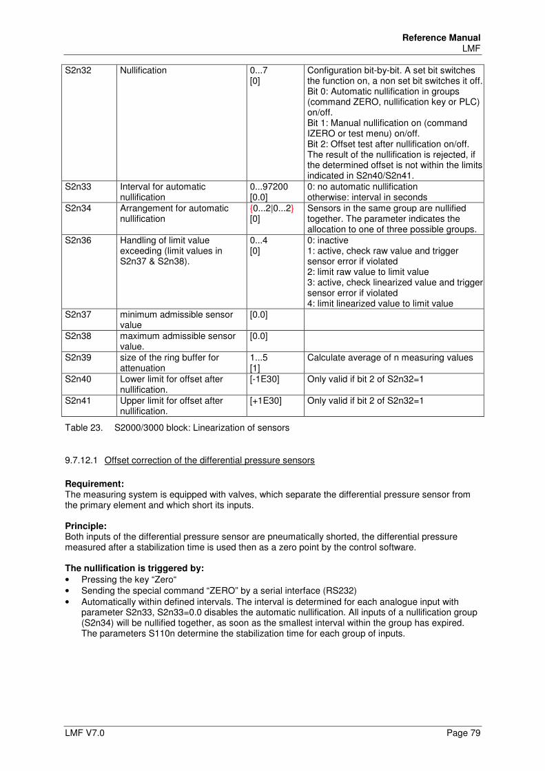
Reference Manual LMF
LMF V7.0 Page 79
S2n32 Nullification 0...7 [0]
Configuration bit-by-bit. A set bit switches the function on, a non set bit switches it off. Bit 0: Automatic nullification in groups (command ZERO, nullification key or PLC) on/off. Bit 1: Manual nullification on (command IZERO or test menu) on/off. Bit 2: Offset test after nullification on/off. The result of the nullification is rejected, if the determined offset is not within the limits indicated in S2n40/S2n41.
S2n33 Interval for automatic nullification
0...97200 [0.0]
0: no automatic nullification otherwise: interval in seconds
S2n34 Arrangement for automatic nullification
{0...2|0...2} [0]
Sensors in the same group are nullified together. The parameter indicates the allocation to one of three possible groups.
S2n36 Handling of limit value exceeding (limit values in S2n37 & S2n38).
0...4 [0]
0: inactive 1: active, check raw value and trigger sensor error if violated 2: limit raw value to limit value 3: active, check linearized value and trigger sensor error if violated 4: limit linearized value to limit value
S2n37 minimum admissible sensor value
[0.0]
S2n38 maximum admissible sensor value.
[0.0]
S2n39 size of the ring buffer for attenuation
1...5 [1]
Calculate average of n measuring values
S2n40 Lower limit for offset after nullification.
[-1E30] Only valid if bit 2 of S2n32=1
S2n41 Upper limit for offset after nullification.
[+1E30] Only valid if bit 2 of S2n32=1
Table 23. S2000/3000 block: Linearization of sensors
9.7.12.1 Offset correction of the differential pressure sensors
Requirement: The measuring system is equipped with valves, which separate the differential pressure sensor from the primary element and which short its inputs. Principle: Both inputs of the differential pressure sensor are pneumatically shorted, the differential pressure measured after a stabilization time is used then as a zero point by the control software. The nullification is triggered by:
• Pressing the key “Zero“ • Sending the special command “ZERO” by a serial interface (RS232) • Automatically within defined intervals. The interval is determined for each analogue input with
parameter S2n33, S2n33=0.0 disables the automatic nullification. All inputs of a nullification group (S2n34) will be nullified together, as soon as the smallest interval within the group has expired. The parameters S110n determine the stabilization time for each group of inputs.
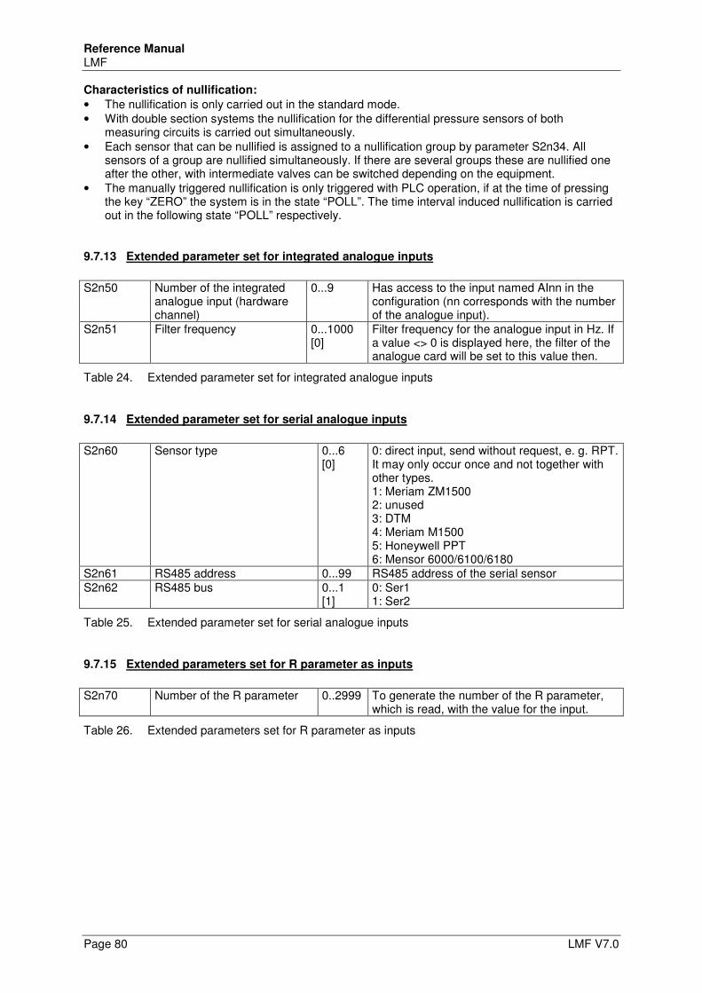
Reference Manual LMF
Page 80 LMF V7.0
Characteristics of nullification:
• The nullification is only carried out in the standard mode. • With double section systems the nullification for the differential pressure sensors of both
measuring circuits is carried out simultaneously. • Each sensor that can be nullified is assigned to a nullification group by parameter S2n34. All
sensors of a group are nullified simultaneously. If there are several groups these are nullified one after the other, with intermediate valves can be switched depending on the equipment.
• The manually triggered nullification is only triggered with PLC operation, if at the time of pressing the key “ZERO” the system is in the state “POLL”. The time interval induced nullification is carried out in the following state “POLL” respectively.
9.7.13 Extended parameter set for integrated analogue inputs
S2n50 Number of the integrated
analogue input (hardware channel)
0...9 Has access to the input named AInn in the configuration (nn corresponds with the number of the analogue input).
S2n51 Filter frequency 0...1000 [0]
Filter frequency for the analogue input in Hz. If a value <> 0 is displayed here, the filter of the analogue card will be set to this value then.
Table 24. Extended parameter set for integrated analogue inputs
9.7.14 Extended parameter set for serial analogue inputs
S2n60 Sensor type
0...6 [0]
0: direct input, send without request, e. g. RPT. It may only occur once and not together with other types. 1: Meriam ZM1500 2: unused 3: DTM 4: Meriam M1500 5: Honeywell PPT 6: Mensor 6000/6100/6180
S2n61 RS485 address 0...99 RS485 address of the serial sensor S2n62 RS485 bus 0...1
[1] 0: Ser1 1: Ser2
Table 25. Extended parameter set for serial analogue inputs
9.7.15 Extended parameters set for R parameter as inputs
S2n70 Number of the R parameter 0..2999 To generate the number of the R parameter,
which is read, with the value for the input.
Table 26. Extended parameters set for R parameter as inputs
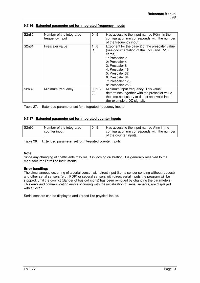
Reference Manual LMF
LMF V7.0 Page 81
9.7.16 Extended parameter set for integrated frequency inputs
S2n80 Number of the integrated
frequency input 0...9 Has access to the input named FQnn in the
configuration (nn corresponds with the number of the frequency input).
S2n81 Prescaler value 1...8 [1]
Exponent for the base 2 of the prescaler value (see documentation of the T500 and T510 cards). 1: Prescaler 2 2: Prescaler 4 3: Prescaler 8 4: Prescaler 16 5: Prescaler 32 6: Prescaler 64 7: Prescaler 128 8: Prescaler 256
S2n82 Minimum frequency 0..5E7 [0]
Minimum input frequency. This value determines together with the prescaler value the time necessary to detect an invalid input (for example a DC signal).
Table 27. Extended parameter set for integrated frequency inputs
9.7.17 Extended parameter set for integrated counter inputs
S2n90 Number of the integrated
counter input 0...9 Has access to the input named AInn in the
configuration (nn corresponds with the number of the counter input).
Table 28. Extended parameter set for integrated counter inputs
Note: Since any changing of coefficients may result in loosing calibration, it is generally reserved to the manufacturer TetraTec Instruments. Error handling: The simultaneous occurring of a serial sensor with direct input (i.e., a sensor sending without request) and other serial sensors (e.g., PDP) or several sensors with direct serial inputs the program will be stopped, until the conflict (danger of bus collisions) has been removed by changing the parameters. This error and communication errors occurring with the initialization of serial sensors, are displayed with a ticker. Serial sensors can be displayed and zeroed like physical inputs.
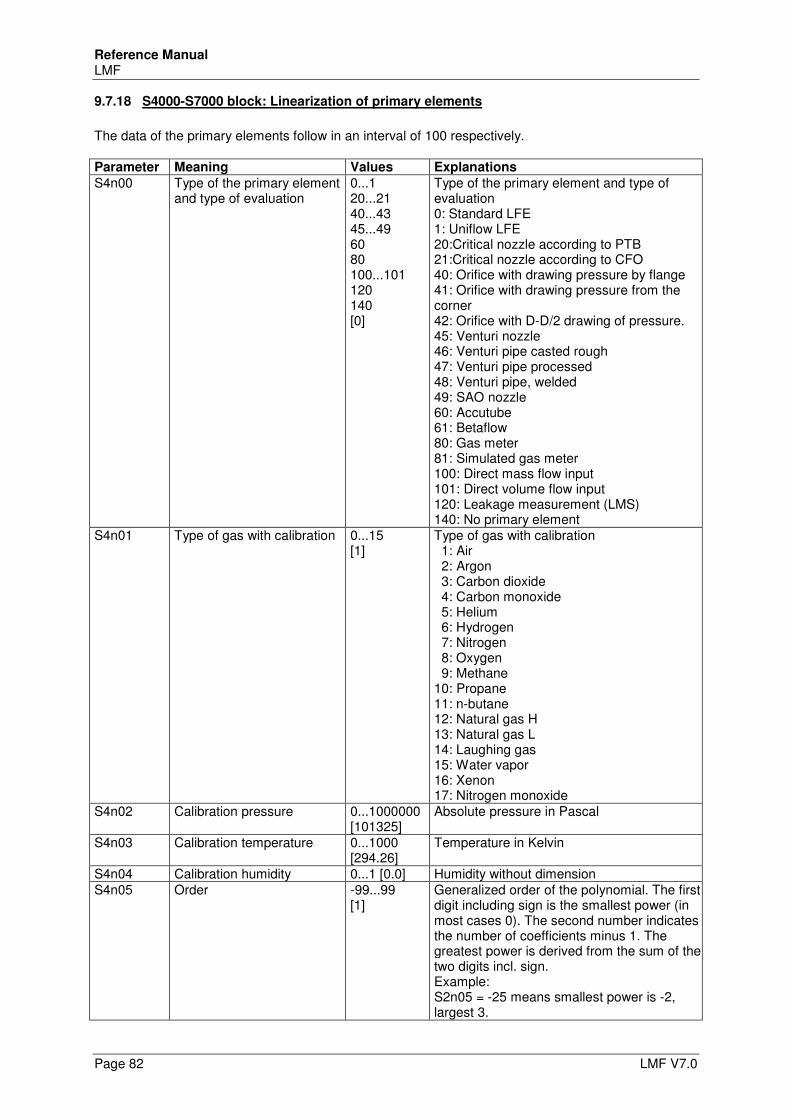
Reference Manual LMF
Page 82 LMF V7.0
9.7.18 S4000-S7000 block: Linearization of primary elements
The data of the primary elements follow in an interval of 100 respectively. Parameter Meaning Values Explanations
S4n00 Type of the primary element and type of evaluation
0...1 20...21 40...43 45...49 60 80 100...101 120 140 [0]
Type of the primary element and type of evaluation 0: Standard LFE 1: Uniflow LFE 20:Critical nozzle according to PTB 21:Critical nozzle according to CFO 40: Orifice with drawing pressure by flange 41: Orifice with drawing pressure from the corner 42: Orifice with D-D/2 drawing of pressure. 45: Venturi nozzle 46: Venturi pipe casted rough 47: Venturi pipe processed 48: Venturi pipe, welded 49: SAO nozzle 60: Accutube 61: Betaflow 80: Gas meter 81: Simulated gas meter 100: Direct mass flow input 101: Direct volume flow input 120: Leakage measurement (LMS) 140: No primary element
S4n01 Type of gas with calibration 0...15 [1]
Type of gas with calibration 1: Air 2: Argon 3: Carbon dioxide 4: Carbon monoxide 5: Helium 6: Hydrogen 7: Nitrogen 8: Oxygen 9: Methane 10: Propane 11: n-butane 12: Natural gas H 13: Natural gas L 14: Laughing gas 15: Water vapor 16: Xenon 17: Nitrogen monoxide
S4n02 Calibration pressure 0...1000000 [101325]
Absolute pressure in Pascal
S4n03 Calibration temperature 0...1000 [294.26]
Temperature in Kelvin
S4n04 Calibration humidity 0...1 [0.0] Humidity without dimension S4n05 Order -99...99
[1] Generalized order of the polynomial. The first digit including sign is the smallest power (in most cases 0). The second number indicates the number of coefficients minus 1. The greatest power is derived from the sum of the two digits incl. sign. Example: S2n05 = -25 means smallest power is -2, largest 3.
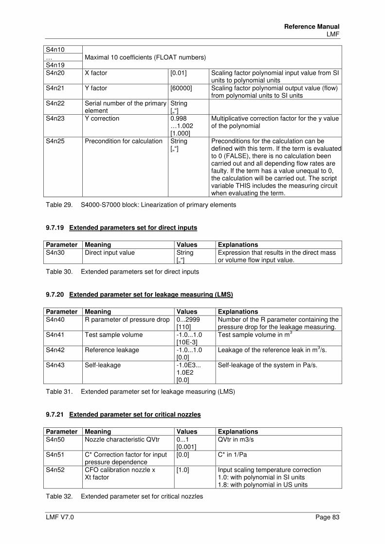
Reference Manual LMF
LMF V7.0 Page 83
S4n10 Maximal 10 coefficients (FLOAT numbers) …
S4n19 S4n20 X factor [0.01] Scaling factor polynomial input value from SI
units to polynomial units S4n21 Y factor [60000] Scaling factor polynomial output value (flow)
from polynomial units to SI units S4n22 Serial number of the primary
element String [„“]
S4n23 Y correction 0.998 …1.002 [1.000]
Multiplicative correction factor for the y value of the polynomial
S4n25 Precondition for calculation String [„“]
Preconditions for the calculation can be defined with this term. If the term is evaluated to 0 (FALSE), there is no calculation been carried out and all depending flow rates are faulty. If the term has a value unequal to 0, the calculation will be carried out. The script variable THIS includes the measuring circuit when evaluating the term.
Table 29. S4000-S7000 block: Linearization of primary elements
9.7.19 Extended parameters set for direct inputs
Parameter Meaning Values Explanations
S4n30 Direct input value String [„“]
Expression that results in the direct mass or volume flow input value.
Table 30. Extended parameters set for direct inputs
9.7.20 Extended parameter set for leakage measuring (LMS)
Parameter Meaning Values Explanations
S4n40 R parameter of pressure drop 0...2999 [110]
Number of the R parameter containing the pressure drop for the leakage measuring.
S4n41 Test sample volume -1.0...1.0 [10E-3]
Test sample volume in m3
S4n42 Reference leakage -1.0...1.0 [0.0]
Leakage of the reference leak in m3/s.
S4n43 Self-leakage -1.0E3... 1.0E2 [0.0]
Self-leakage of the system in Pa/s.
Table 31. Extended parameter set for leakage measuring (LMS)
9.7.21 Extended parameter set for critical nozzles
Parameter Meaning Values Explanations
S4n50 Nozzle characteristic QVtr 0...1 [0.001]
QVtr in m3/s
S4n51 C* Correction factor for input pressure dependence
[0.0] C* in 1/Pa
S4n52 CFO calibration nozzle x Xt factor
[1.0] Input scaling temperature correction 1.0: with polynomial in SI units 1.8: with polynomial in US units
Table 32. Extended parameter set for critical nozzles
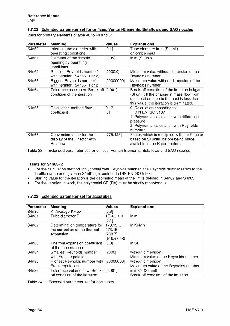
Reference Manual LMF
Page 84 LMF V7.0
9.7.22 Extended parameter set for orifices, Venturi-Elements, Betaflows and SAO nozzles
Valid for primary elements of type 40 to 49 and 61 Parameter Meaning Values Explanations
S4n60 Internal tube diameter with operating conditions
[0.1] Tube diameter in m (SI unit). on orifice input
S4n61 Diameter of the throttle opening by operating conditions
[0.05] in m (SI unit)
S4n62 Smallest Reynolds number* with iteration (S4n66=1 or 2)
[2000.0] Minimum value without dimension of the Reynolds number
S4n63 Biggest Reynolds number* with iteration (S4n66=1 or 2)
[20000000] Maximum value without dimension of the Reynolds number
S4n64 Tolerance mass flow: Break-off condition of the iteration
[0.001] Break-off condition of the iteration in kg/s (SI unit): If the change in mass flow from one iteration step to the next is less than this value, the iteration is terminated.
S4n65 Calculation method flow coefficient
0...2 [0]
0: Calculation according to DIN EN ISO 5167 1: Polynomial calculation with differential pressure 2: Polynomial calculation with Reynolds number*
S4n66 Conversion factor for the display of the K factor with Betaflow
[775.428] Factor, which is multiplied with the K factor based on SI units, before being made available in the R parameters.
Table 33. Extended parameter set for orifices, Venturi-Elements, Betaflows and SAO nozzles
* Hints for S4n65=2
• For the calculation method "polynomial over Reynolds number" the Reynolds number refers to the throttle diameter d, given in S4n61. (In contrast to DIN EN ISO 5167)
• Starting value for the iteration is the geometric mean of the limits defined in S4n62 and S4n63 • For the iteration to work, the polynomial CD (Re) must be strictly monotonous.
9.7.23 Extended parameter set for accutubes
Parameter Meaning Values Explanations
S4n80 K: Average KFlow [0.6] S4n81 Tube diameter DI 1E-4…1.0
[0.1] in m
S4n82 Determination temperature for the correction of the thermal expansion
173.15… 473.15 [288.7] (519.67 °R)
in Kelvin
S4n83 Thermal expansion coefficient of the tube material
[0.0] in SI
S4n84 Smallest Reynolds number with Fra interpolation
[2000] without dimension Minimum value of the Reynolds number
S4n85 Highest Reynolds number with Fra interpolation
[20000000] without dimension Maximum value of the Reynolds number
S4n86 Tolerance volume flow: Break-off condition of the iteration
[0.001] in m3/s (SI unit) Break-off condition of the iteration
Table 34. Extended parameter set for accutubes
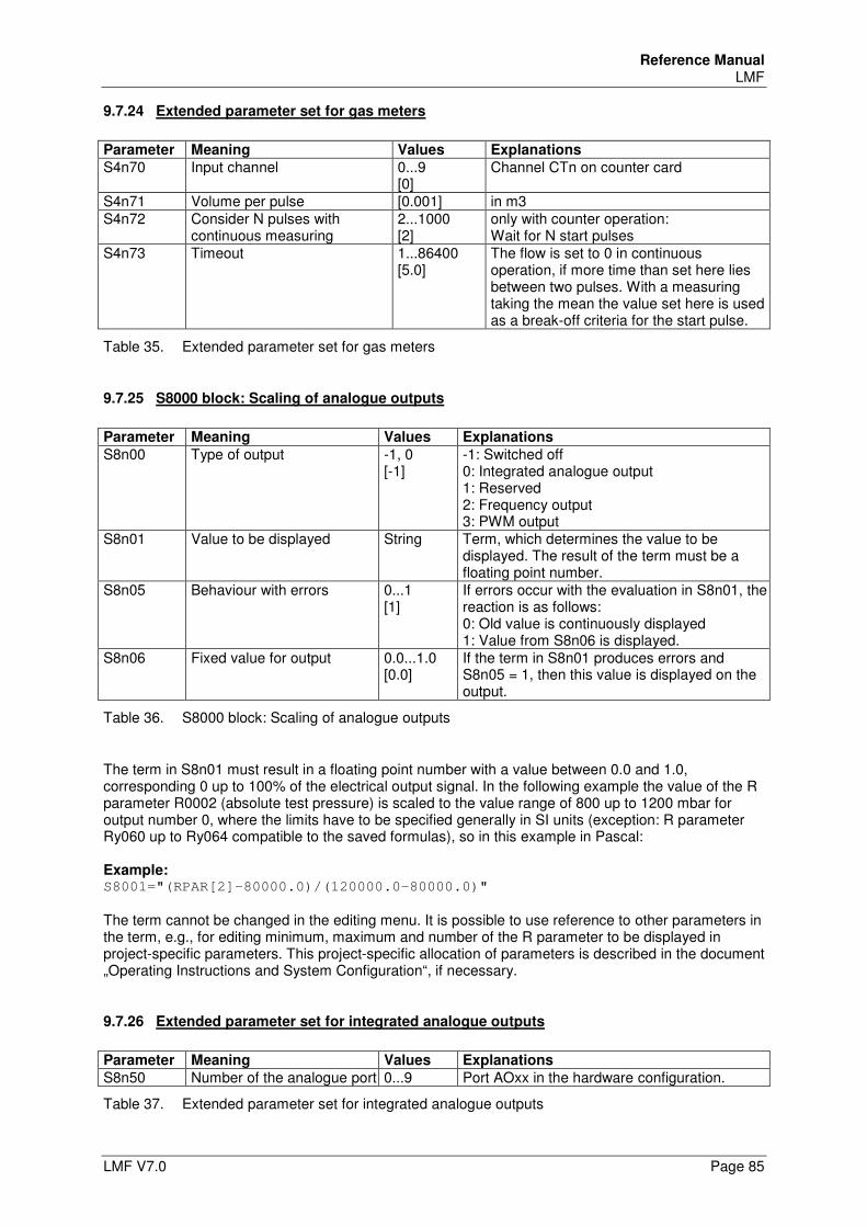
Reference Manual LMF
LMF V7.0 Page 85
9.7.24 Extended parameter set for gas meters
Parameter Meaning Values Explanations
S4n70 Input channel 0...9 [0]
Channel CTn on counter card
S4n71 Volume per pulse [0.001] in m3 S4n72 Consider N pulses with
continuous measuring 2...1000 [2]
only with counter operation: Wait for N start pulses
S4n73 Timeout 1...86400 [5.0]
The flow is set to 0 in continuous operation, if more time than set here lies between two pulses. With a measuring taking the mean the value set here is used as a break-off criteria for the start pulse.
Table 35. Extended parameter set for gas meters
9.7.25 S8000 block: Scaling of analogue outputs
Parameter Meaning Values Explanations
S8n00 Type of output -1, 0 [-1]
-1: Switched off 0: Integrated analogue output 1: Reserved 2: Frequency output 3: PWM output
S8n01 Value to be displayed String Term, which determines the value to be displayed. The result of the term must be a floating point number.
S8n05 Behaviour with errors 0...1 [1]
If errors occur with the evaluation in S8n01, the reaction is as follows: 0: Old value is continuously displayed 1: Value from S8n06 is displayed.
S8n06 Fixed value for output 0.0...1.0 [0.0]
If the term in S8n01 produces errors and S8n05 = 1, then this value is displayed on the output.
Table 36. S8000 block: Scaling of analogue outputs
The term in S8n01 must result in a floating point number with a value between 0.0 and 1.0, corresponding 0 up to 100% of the electrical output signal. In the following example the value of the R parameter R0002 (absolute test pressure) is scaled to the value range of 800 up to 1200 mbar for output number 0, where the limits have to be specified generally in SI units (exception: R parameter Ry060 up to Ry064 compatible to the saved formulas), so in this example in Pascal: Example: S8001="(RPAR[2]-80000.0)/(120000.0-80000.0)"
The term cannot be changed in the editing menu. It is possible to use reference to other parameters in the term, e.g., for editing minimum, maximum and number of the R parameter to be displayed in project-specific parameters. This project-specific allocation of parameters is described in the document „Operating Instructions and System Configuration“, if necessary.
9.7.26 Extended parameter set for integrated analogue outputs
Parameter Meaning Values Explanations
S8n50 Number of the analogue port 0...9 Port AOxx in the hardware configuration.
Table 37. Extended parameter set for integrated analogue outputs
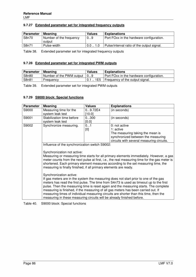
Reference Manual LMF
Page 86 LMF V7.0
9.7.27 Extended parameter set for integrated frequency outputs
Parameter Meaning Values Explanations
S8n70 Number of the frequency output
0...9 Port FOxx in the hardware configuration.
S8n71 Pulse-width 0.0 .. 1.0 Pulse/interval ratio of the output signal.
Table 38. Extended parameter set for integrated frequency outputs
9.7.28 Extended parameter set for integrated PWM outputs
Parameter Meaning Values Explanations
S8n80 Number of the PWM output 0...9 Port FOxx in the hardware configuration. S8n81 Frequency 0.1 .. 1E5 Frequency of the output signal.
Table 39. Extended parameter set for integrated PWM outputs
9.7.29 S9000 block: Special functions
Parameter Meaning Values Explanations
S9000 Measuring time for the system leak test
0...9.72E4 [10.0]
(in seconds)
S9001 Stabilization time before system leak test
0...300 [0.0]
(in seconds)
S9002 Synchronize measuring. 0...1 [0]
0: not active 1: active The measuring taking the mean is synchronized between the measuring circuits with several measuring circuits.
Influence of the synchronization switch S9002: Synchronization not active: Measuring or measuring time starts for all primary elements immediately. However, a gas meter counts from the next pulse at first, i.e., the real measuring time for the gas meter is shortened. Each primary element measures according to the set measuring time, the measuring is finally finished, if all primary elements are ready. Synchronization active: If gas meters are in the system the measuring does not start prior to one of the gas meters has read the first pulse. The time from S4n73 is used as timeout up to the first pulse. Then the measuring time is reset again and the measuring starts. The complete measuring is finished, if the measuring of all gas meters has been carried out. If measuring times of individual measuring circuits are shorter than this time, then the measuring in these measuring circuits will be already finished before.
Table 40. S9000 block: Special functions
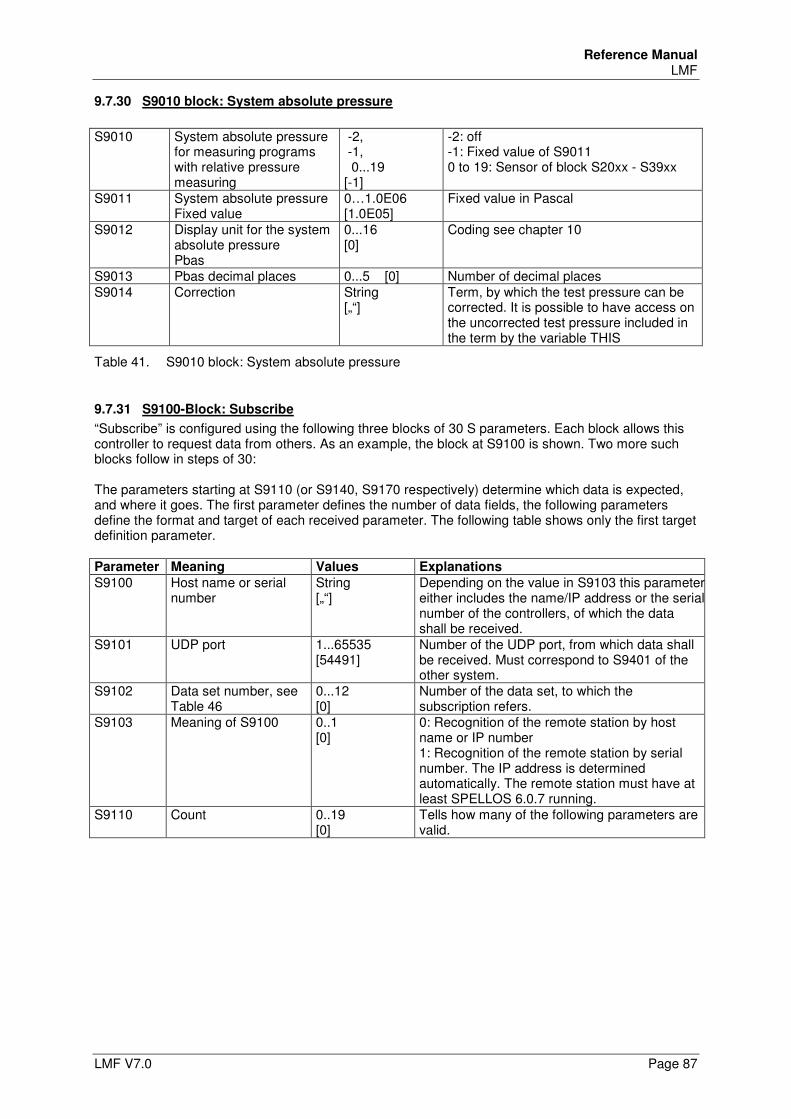
Reference Manual LMF
LMF V7.0 Page 87
9.7.30 S9010 block: System absolute pressure
S9010 System absolute pressure
for measuring programs with relative pressure measuring
-2, -1, 0...19 [-1]
-2: off -1: Fixed value of S9011 0 to 19: Sensor of block S20xx - S39xx
S9011 System absolute pressure Fixed value
0…1.0E06 [1.0E05]
Fixed value in Pascal
S9012 Display unit for the system absolute pressure Pbas
0...16 [0]
Coding see chapter 10
S9013 Pbas decimal places 0...5 [0] Number of decimal places S9014 Correction String
[„“] Term, by which the test pressure can be corrected. It is possible to have access on the uncorrected test pressure included in the term by the variable THIS
Table 41. S9010 block: System absolute pressure
9.7.31 S9100-Block: Subscribe
“Subscribe” is configured using the following three blocks of 30 S parameters. Each block allows this controller to request data from others. As an example, the block at S9100 is shown. Two more such blocks follow in steps of 30: The parameters starting at S9110 (or S9140, S9170 respectively) determine which data is expected, and where it goes. The first parameter defines the number of data fields, the following parameters define the format and target of each received parameter. The following table shows only the first target definition parameter. Parameter Meaning Values Explanations
S9100 Host name or serial number
String [„“]
Depending on the value in S9103 this parameter either includes the name/IP address or the serial number of the controllers, of which the data shall be received.
S9101 UDP port 1...65535 [54491]
Number of the UDP port, from which data shall be received. Must correspond to S9401 of the other system.
S9102 Data set number, see Table 46
0...12 [0]
Number of the data set, to which the subscription refers.
S9103 Meaning of S9100 0..1 [0]
0: Recognition of the remote station by host name or IP number 1: Recognition of the remote station by serial number. The IP address is determined automatically. The remote station must have at least SPELLOS 6.0.7 running.
S9110 Count 0..19 [0]
Tells how many of the following parameters are valid.
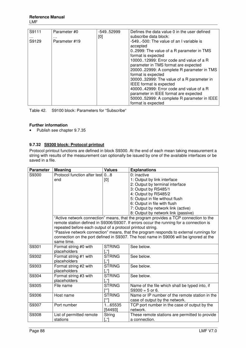
Reference Manual LMF
Page 88 LMF V7.0
S9111 … S9129
Parameter #0 … Parameter #19
-549..52999 [0]
Defines the data value 0 in the user defined subscribe data block: -549..-500: The value of an I variable is accepted 0..2999: The value of a R parameter in TMS format is expected 10000..12999: Error code and value of a R parameter in TMS format are expected 20000..22999: A complete R parameter in TMS format is expected 30000..32999: The value of a R parameter in IEEE format is expected 40000..42999: Error code and value of a R parameter in IEEE format are expected 50000..52999: A complete R parameter in IEEE format is expected
Table 42. S9100 block: Parameters for “Subscribe“
Further information
• Publish see chapter 9.7.35
9.7.32 S9300 block: Protocol printout
Protocol printout functions are defined in block S9300. At the end of each mean taking measurement a string with results of the measurement can optionally be issued by one of the available interfaces or be saved in a file. Parameter Meaning Values Explanations
S9300 Protocol function after test end
0...8 [0]
0: inactive 1: Output by link interface 2: Output by terminal interface 3: Output by RS485/1 4: Output by RS485/2 5: Output in file without flush 6: Output in file with flush 7: Output by network link (active) 8: Output by network link (passive)
“Active network connection” means, that the program provides a TCP connection to the remote station defined in S9306/S9307. If errors occur the running for a connection is repeated before each output of a protocol printout string. “Passive network connection” means, that the program responds to external runnings for connection on the port defined in S9307. The host name in S9006 will be ignored at the same time.
S9301 Format string #0 with placeholders
STRING [„“]
See below.
S9302 Format string #1 with placeholders
STRING [„“]
See below.
S9303 Format string #2 with placeholders
STRING [„“]
See below.
S9304 Format string #3 with placeholders
STRING [„“]
See below.
S9305 File name STRING [“”]
Name of the file which shall be typed into, if S9300 = 5 or 6.
S9306 Host name STRING [“”]
Name or IP number of the remote station in the case of output by the network.
S9307 Port number 1...65535 [54493]
TCP port number in the case of output by the network.
S9308 List of permitted remote stations
String [„“]
These remote stations are permitted to provide a connection.
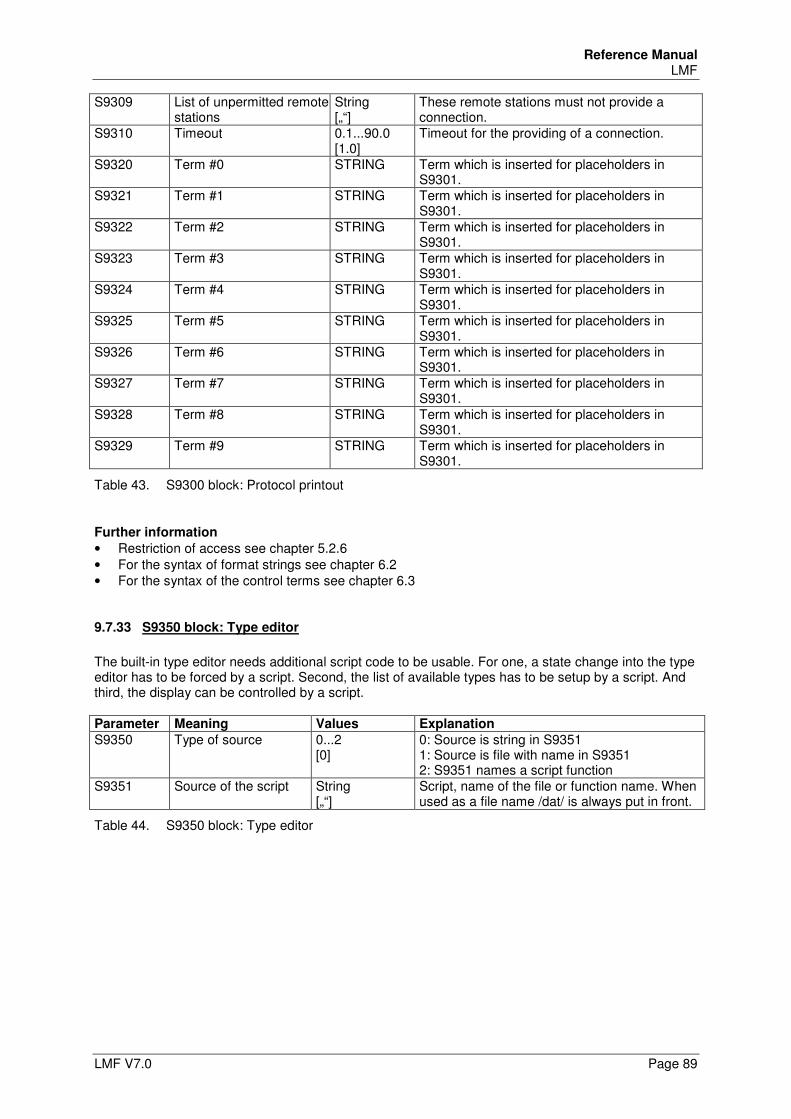
Reference Manual LMF
LMF V7.0 Page 89
S9309 List of unpermitted remote stations
String [„“]
These remote stations must not provide a connection.
S9310 Timeout 0.1...90.0 [1.0]
Timeout for the providing of a connection.
S9320 Term #0 STRING Term which is inserted for placeholders in S9301.
S9321 Term #1 STRING Term which is inserted for placeholders in S9301.
S9322 Term #2 STRING Term which is inserted for placeholders in S9301.
S9323 Term #3 STRING Term which is inserted for placeholders in S9301.
S9324 Term #4 STRING Term which is inserted for placeholders in S9301.
S9325 Term #5 STRING Term which is inserted for placeholders in S9301.
S9326 Term #6 STRING Term which is inserted for placeholders in S9301.
S9327 Term #7 STRING Term which is inserted for placeholders in S9301.
S9328 Term #8 STRING Term which is inserted for placeholders in S9301.
S9329 Term #9 STRING Term which is inserted for placeholders in S9301.
Table 43. S9300 block: Protocol printout
Further information
• Restriction of access see chapter 5.2.6 • For the syntax of format strings see chapter 6.2 • For the syntax of the control terms see chapter 6.3
9.7.33 S9350 block: Type editor
The built-in type editor needs additional script code to be usable. For one, a state change into the type editor has to be forced by a script. Second, the list of available types has to be setup by a script. And third, the display can be controlled by a script. Parameter Meaning Values Explanation
S9350 Type of source 0...2 [0]
0: Source is string in S9351 1: Source is file with name in S9351 2: S9351 names a script function
S9351 Source of the script String [„“]
Script, name of the file or function name. When used as a file name /dat/ is always put in front.
Table 44. S9350 block: Type editor
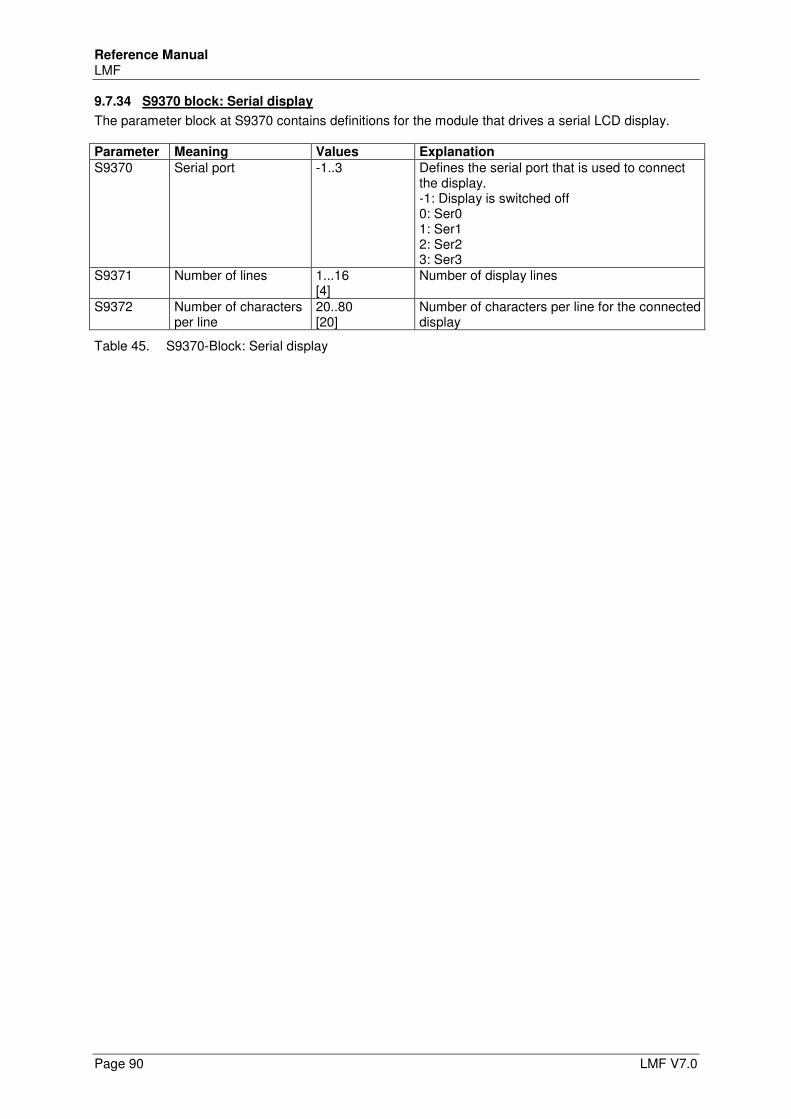
Reference Manual LMF
Page 90 LMF V7.0
9.7.34 S9370 block: Serial display
The parameter block at S9370 contains definitions for the module that drives a serial LCD display. Parameter Meaning Values Explanation
S9370 Serial port -1..3 Defines the serial port that is used to connect the display. -1: Display is switched off 0: Ser0 1: Ser1 2: Ser2 3: Ser3
S9371 Number of lines 1...16 [4]
Number of display lines
S9372 Number of characters per line
20..80 [20]
Number of characters per line for the connected display
Table 45. S9370-Block: Serial display
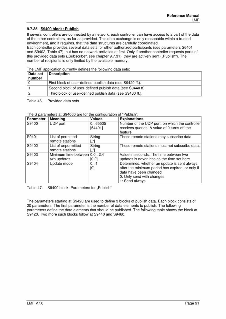
Reference Manual LMF
LMF V7.0 Page 91
9.7.35 S9400 block: Publish
If several controllers are connected by a network, each controller can have access to a part of the data of the other controllers, as far as provided. This data exchange is only reasonable within a trusted environment, and it requires, that the data structures are carefully coordinated. Each controller provides several data sets for other authorized participants (see parameters S6401 and S9402, Table 47), but has no network activities at first. Only if another controller requests parts of this provided data sets („Subscribe“, see chapter 9.7.31), they are actively sent („Publish“). The number of recipients is only limited by the available memory. The LMF application currently defines the following data sets: Data set number
Description
0 First block of user-defined publish data (see S9420 ff.).
1 Second block of user-defined publish data (see S9440 ff).
2 Third block of user-defined publish data (see S9460 ff.).
Table 46. Provided data sets
The S parameters at S94000 are for the configuration of “Publish”: Parameter Meaning Values Explanations
S9400 UDP port 0...65535 [54491]
Number of the UDP port, on which the controller receives queries. A value of 0 turns off the feature.
S9401 List of permitted remote stations
String [„“]
These remote stations may subscribe data.
S9402 List of unpermitted remote stations
String [„“]
These remote stations must not subscribe data.
S9403 Minimum time between two updates
0.0...2.4 [0.2]
Value in seconds. The time between two updates is never less as the time set here.
S9404 Update mode 0...1 [0]
Determines, whether an update is sent always after the minimum period has expired, or only if data have been changed. 0: Only send with changes 1: Send always
Table 47. S9400 block: Parameters for „Publish“
The parameters starting at S9420 are used to define 3 blocks of publish data. Each block consists of 20 parameters. The first parameter is the number of data elements to publish. The following parameters define the data elements that should be published. The following table shows the block at S9420. Two more such blocks follow at S9440 and S9460.
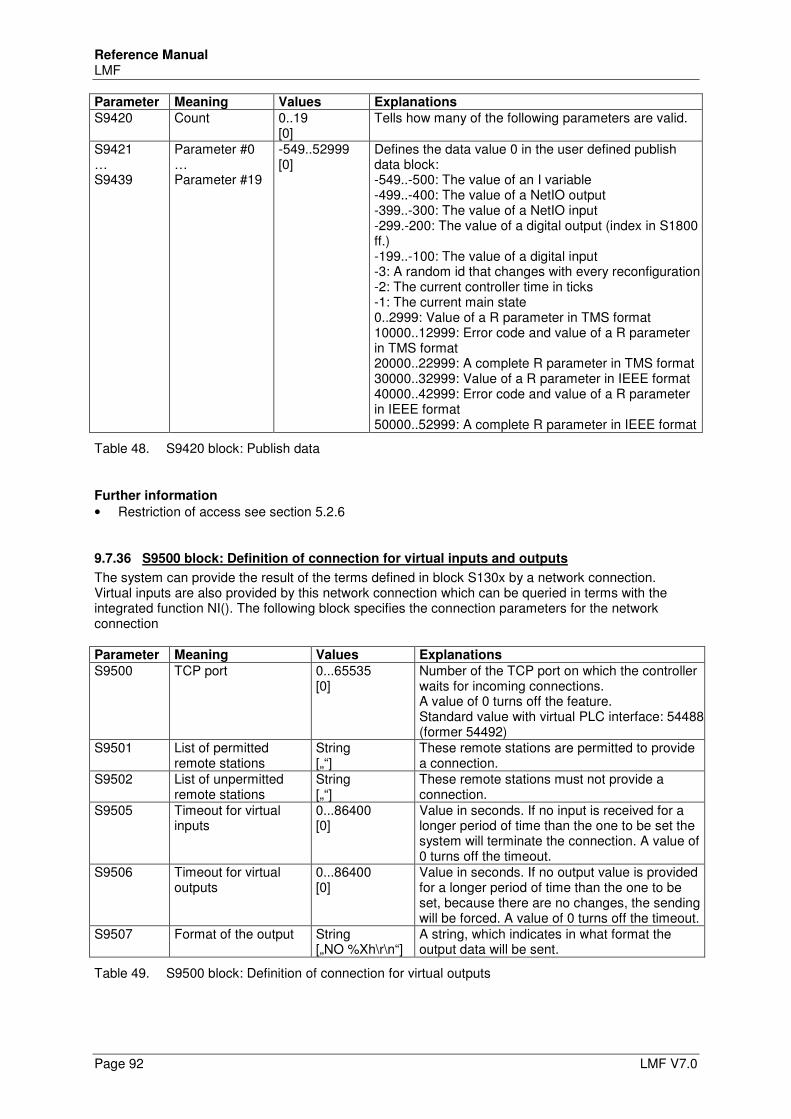
Reference Manual LMF
Page 92 LMF V7.0
Parameter Meaning Values Explanations
S9420 Count 0..19 [0]
Tells how many of the following parameters are valid.
S9421 … S9439
Parameter #0 … Parameter #19
-549..52999 [0]
Defines the data value 0 in the user defined publish data block: -549..-500: The value of an I variable -499..-400: The value of a NetIO output -399..-300: The value of a NetIO input -299.-200: The value of a digital output (index in S1800 ff.) -199..-100: The value of a digital input -3: A random id that changes with every reconfiguration -2: The current controller time in ticks -1: The current main state 0..2999: Value of a R parameter in TMS format 10000..12999: Error code and value of a R parameter in TMS format 20000..22999: A complete R parameter in TMS format 30000..32999: Value of a R parameter in IEEE format 40000..42999: Error code and value of a R parameter in IEEE format 50000..52999: A complete R parameter in IEEE format
Table 48. S9420 block: Publish data
Further information
• Restriction of access see section 5.2.6
9.7.36 S9500 block: Definition of connection for virtual inputs and outputs
The system can provide the result of the terms defined in block S130x by a network connection. Virtual inputs are also provided by this network connection which can be queried in terms with the integrated function NI(). The following block specifies the connection parameters for the network connection Parameter Meaning Values Explanations
S9500 TCP port 0...65535 [0]
Number of the TCP port on which the controller waits for incoming connections. A value of 0 turns off the feature. Standard value with virtual PLC interface: 54488 (former 54492)
S9501 List of permitted remote stations
String [„“]
These remote stations are permitted to provide a connection.
S9502 List of unpermitted remote stations
String [„“]
These remote stations must not provide a connection.
S9505 Timeout for virtual inputs
0...86400 [0]
Value in seconds. If no input is received for a longer period of time than the one to be set the system will terminate the connection. A value of 0 turns off the timeout.
S9506 Timeout for virtual outputs
0...86400 [0]
Value in seconds. If no output value is provided for a longer period of time than the one to be set, because there are no changes, the sending will be forced. A value of 0 turns off the timeout.
S9507 Format of the output String [„NO %Xh\r\n“]
A string, which indicates in what format the output data will be sent.
Table 49. S9500 block: Definition of connection for virtual outputs
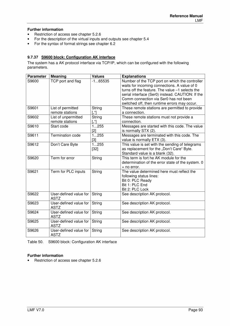
Reference Manual LMF
LMF V7.0 Page 93
Further information
• Restriction of access see chapter 5.2.6 • For the description of the virtual inputs and outputs see chapter 5.4 • For the syntax of format strings see chapter 6.2
9.7.37 S9600 block: Configuration AK interface
The system has a AK protocol interface via TCP/IP, which can be configured with the following parameters. Parameter Meaning Values Explanations
S9600 TCP port and flag -1...65535 Number of the TCP port on which the controller waits for incoming connections. A value of 0 turns off the feature. The value –1 selects the serial interface (Ser0) instead. CAUTION: If the Comm connection via Ser0 has not been switched off, then runtime errors may occur.
S9601 List of permitted remote stations
String [„“]
These remote stations are permitted to provide a connection.
S9602 List of unpermitted remote stations
String [„“]
These remote stations must not provide a connection.
S9610 Start code 1...255 [2]
Messages are started with this code. The value is normally STX (2).
S9611 Termination code 1...255 [3]
Messages are terminated with this code. The value is normally ETX (3).
S9612 Don’t Care Byte 1...255 [32]
This value is set with the sending of telegrams as replacement for the „Don’t Care“ Byte. Standard value is a blank (32).
S9620 Term for error String This term is fort he AK module for the determination of the error state of the system. 0 = no error.
S9621 Term for PLC inputs String The value determined here must reflect the following status lines: Bit 0: PLC Ready Bit 1: PLC End Bit 2: PLC Lock
S9622 User-defined value for ASTZ
String See description AK protocol.
S9623 User-defined value for ASTZ
String See description AK protocol.
S9624 User-defined value for ASTZ
String See description AK protocol.
S9625 User-defined value for ASTZ
String See description AK protocol.
S9626 User-defined value for ASTZ
String See description AK protocol.
Table 50. S9600 block: Configuration AK interface
Further information
• Restriction of access see chapter 5.2.6
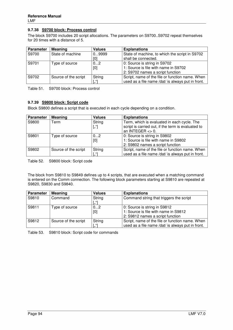
Reference Manual LMF
Page 94 LMF V7.0
9.7.38 S9700 block: Process control
The block S9700 includes 20 script allocations. The parameters on S9700..S9702 repeat themselves for 20 times with a distance of 5. Parameter Meaning Values Explanations
S9700 State of machine 0...9999 [0]
State of machine, to which the script in S9702 shall be connected.
S9701 Type of source 0...2 [0]
0: Source is string in S9702 1: Source is file with name in S9702 2: S9702 names a script function
S9702 Source of the script String [„“]
Script, name of the file or function name. When used as a file name /dat/ is always put in front.
Table 51. S9700 block: Process control
9.7.39 S9800 block: Script code
Block S9800 defines a script that is executed in each cycle depending on a condition. Parameter Meaning Values Explanations
S9800 Term String [„“]
Term, which is evaluated in each cycle. The script is carried out, if the term is evaluated to an INTEGER <> 0.
S9801 Type of source 0...2 [0]
0: Source is string in S9802 1: Source is file with name in S9802 2: S9802 names a script function
S9802 Source of the script String [„“]
Script, name of the file or function name. When used as a file name /dat/ is always put in front.
Table 52. S9800 block: Script code
The block from S9810 to S9849 defines up to 4 scripts, that are executed when a matching command is entered on the Comm connection. The following block parameters starting at S9810 are repeated at S9820, S9830 and S9840. Parameter Meaning Values Explanations
S9810 Command String [„“]
Command string that triggers the script
S9811 Type of source 0...2 [0]
0: Source is string in S9812 1: Source is file with name in S9812 2: S9812 names a script function
S9812 Source of the script String [„“]
Script, name of the file or function name. When used as a file name /dat/ is always put in front.
Table 53. S9810 block: Script code for commands
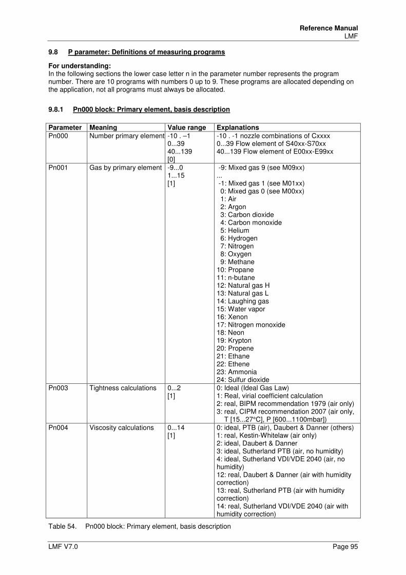
Reference Manual LMF
LMF V7.0 Page 95
9.8 P parameter: Definitions of measuring programs
For understanding: In the following sections the lower case letter n in the parameter number represents the program number. There are 10 programs with numbers 0 up to 9. These programs are allocated depending on the application, not all programs must always be allocated.
9.8.1 Pn000 block: Primary element, basis description
Parameter Meaning Value range Explanations
Pn000 Number primary element -10 . –1 0...39 40...139 [0]
-10 . -1 nozzle combinations of Cxxxx 0...39 Flow element of S40xx-S70xx 40...139 Flow element of E00xx-E99xx
Pn001 Gas by primary element -9...0 1...15 [1]
-9: Mixed gas 9 (see M09xx) ... -1: Mixed gas 1 (see M01xx) 0: Mixed gas 0 (see M00xx) 1: Air 2: Argon 3: Carbon dioxide 4: Carbon monoxide 5: Helium 6: Hydrogen 7: Nitrogen 8: Oxygen 9: Methane 10: Propane 11: n-butane 12: Natural gas H 13: Natural gas L 14: Laughing gas 15: Water vapor 16: Xenon 17: Nitrogen monoxide 18: Neon 19: Krypton 20: Propene 21: Ethane 22: Ethene 23: Ammonia 24: Sulfur dioxide
Pn003 Tightness calculations
0...2 [1]
0: Ideal (Ideal Gas Law) 1: Real, virial coefficient calculation 2: real, BIPM recommendation 1979 (air only) 3: real, CIPM recommendation 2007 (air only, T [15...27°C], P [600...1100mbar])
Pn004 Viscosity calculations 0...14 [1]
0: ideal, PTB (air), Daubert & Danner (others) 1: real, Kestin-Whitelaw (air only) 2: ideal, Daubert & Danner 3: ideal, Sutherland PTB (air, no humidity) 4: ideal, Sutherland VDI/VDE 2040 (air, no humidity) 12: real, Daubert & Danner (air with humidity correction) 13: real, Sutherland PTB (air with humidity correction) 14: real, Sutherland VDI/VDE 2040 (air with humidity correction)
Table 54. Pn000 block: Primary element, basis description
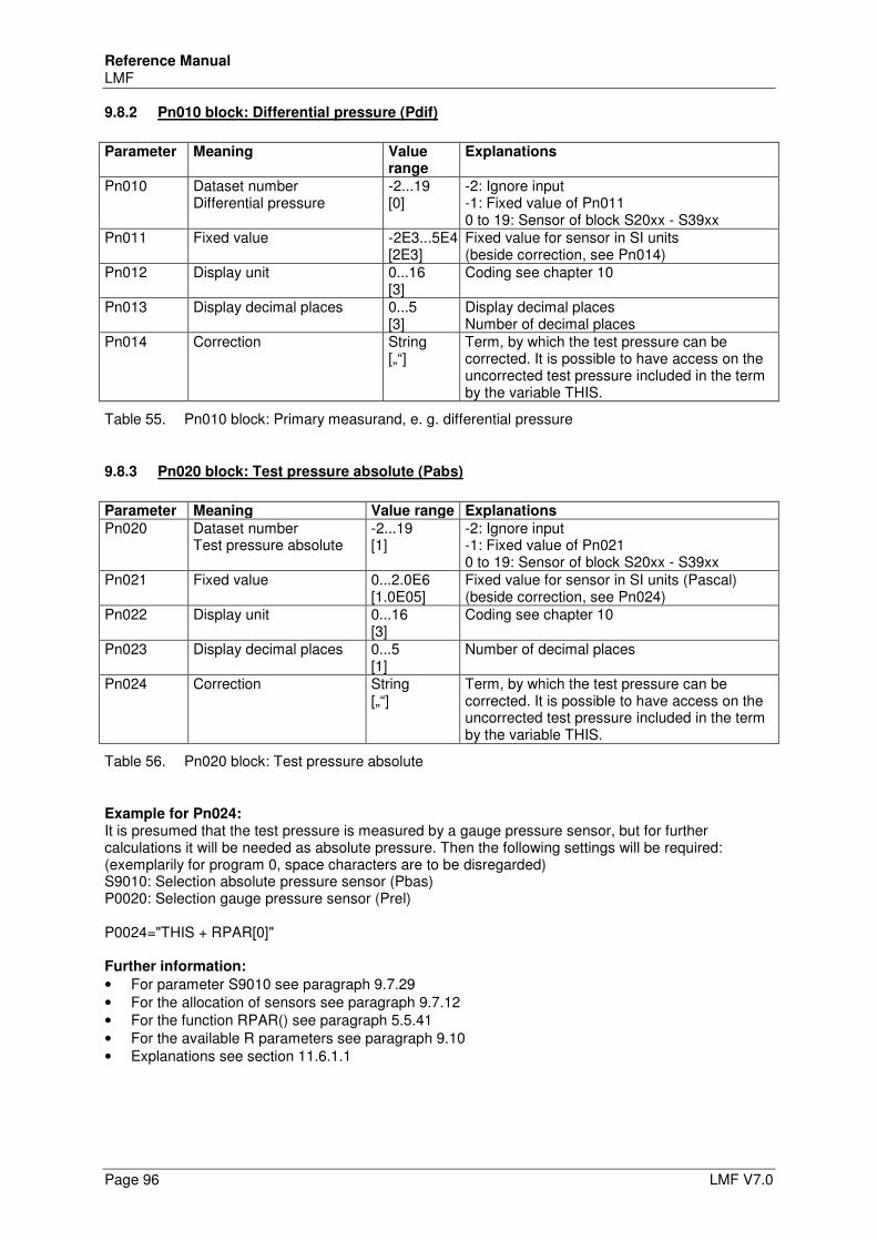
Reference Manual LMF
Page 96 LMF V7.0
9.8.2 Pn010 block: Differential pressure (Pdif)
Parameter Meaning Value
range Explanations
Pn010 Dataset number Differential pressure
-2...19 [0]
-2: Ignore input -1: Fixed value of Pn011 0 to 19: Sensor of block S20xx - S39xx
Pn011 Fixed value -2E3...5E4 [2E3]
Fixed value for sensor in SI units (beside correction, see Pn014)
Pn012 Display unit 0...16 [3]
Coding see chapter 10
Pn013 Display decimal places 0...5 [3]
Display decimal places Number of decimal places
Pn014 Correction String [„“]
Term, by which the test pressure can be corrected. It is possible to have access on the uncorrected test pressure included in the term by the variable THIS.
Table 55. Pn010 block: Primary measurand, e. g. differential pressure
9.8.3 Pn020 block: Test pressure absolute (Pabs)
Parameter Meaning Value range Explanations
Pn020 Dataset number Test pressure absolute
-2...19 [1]
-2: Ignore input -1: Fixed value of Pn021 0 to 19: Sensor of block S20xx - S39xx
Pn021 Fixed value 0...2.0E6 [1.0E05]
Fixed value for sensor in SI units (Pascal) (beside correction, see Pn024)
Pn022 Display unit 0...16 [3]
Coding see chapter 10
Pn023 Display decimal places 0...5 [1]
Number of decimal places
Pn024 Correction String [„“]
Term, by which the test pressure can be corrected. It is possible to have access on the uncorrected test pressure included in the term by the variable THIS.
Table 56. Pn020 block: Test pressure absolute
Example for Pn024: It is presumed that the test pressure is measured by a gauge pressure sensor, but for further calculations it will be needed as absolute pressure. Then the following settings will be required: (exemplarily for program 0, space characters are to be disregarded) S9010: Selection absolute pressure sensor (Pbas) P0020: Selection gauge pressure sensor (Prel) P0024="THIS + RPAR[0]" Further information:
• For parameter S9010 see paragraph 9.7.29 • For the allocation of sensors see paragraph 9.7.12 • For the function RPAR() see paragraph 5.5.41 • For the available R parameters see paragraph 9.10 • Explanations see section 11.6.1.1
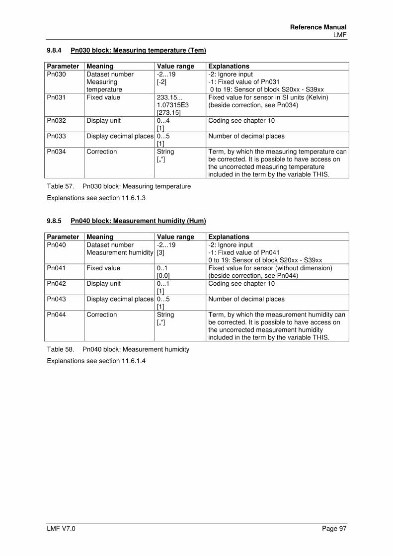
Reference Manual LMF
LMF V7.0 Page 97
9.8.4 Pn030 block: Measuring temperature (Tem)
Parameter Meaning Value range Explanations
Pn030 Dataset number Measuring temperature
-2...19 [-2]
-2: Ignore input -1: Fixed value of Pn031 0 to 19: Sensor of block S20xx - S39xx
Pn031 Fixed value 233.15... 1.07315E3 [273.15]
Fixed value for sensor in SI units (Kelvin) (beside correction, see Pn034)
Pn032 Display unit 0...4 [1]
Coding see chapter 10
Pn033 Display decimal places 0...5 [1]
Number of decimal places
Pn034 Correction String [„“]
Term, by which the measuring temperature can be corrected. It is possible to have access on the uncorrected measuring temperature included in the term by the variable THIS.
Table 57. Pn030 block: Measuring temperature
Explanations see section 11.6.1.3
9.8.5 Pn040 block: Measurement humidity (Hum)
Parameter Meaning Value range Explanations
Pn040 Dataset number Measurement humidity
-2...19 [3]
-2: Ignore input -1: Fixed value of Pn041 0 to 19: Sensor of block S20xx - S39xx
Pn041 Fixed value 0..1 [0.0]
Fixed value for sensor (without dimension) (beside correction, see Pn044)
Pn042 Display unit 0...1 [1]
Coding see chapter 10
Pn043 Display decimal places 0...5 [1]
Number of decimal places
Pn044 Correction String [„“]
Term, by which the measurement humidity can be corrected. It is possible to have access on the uncorrected measurement humidity included in the term by the variable THIS.
Table 58. Pn040 block: Measurement humidity
Explanations see section 11.6.1.4
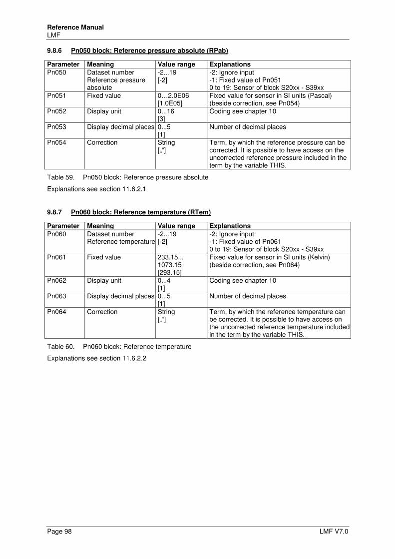
Reference Manual LMF
Page 98 LMF V7.0
9.8.6 Pn050 block: Reference pressure absolute (RPab)
Parameter Meaning Value range Explanations
Pn050 Dataset number Reference pressure absolute
-2...19 [-2]
-2: Ignore input -1: Fixed value of Pn051 0 to 19: Sensor of block S20xx - S39xx
Pn051 Fixed value 0…2.0E06 [1.0E05]
Fixed value for sensor in SI units (Pascal) (beside correction, see Pn054)
Pn052 Display unit 0...16 [3]
Coding see chapter 10
Pn053 Display decimal places 0...5 [1]
Number of decimal places
Pn054 Correction String [„“]
Term, by which the reference pressure can be corrected. It is possible to have access on the uncorrected reference pressure included in the term by the variable THIS.
Table 59. Pn050 block: Reference pressure absolute
Explanations see section 11.6.2.1
9.8.7 Pn060 block: Reference temperature (RTem)
Parameter Meaning Value range Explanations
Pn060 Dataset number Reference temperature
-2...19 [-2]
-2: Ignore input -1: Fixed value of Pn061 0 to 19: Sensor of block S20xx - S39xx
Pn061 Fixed value 233.15... 1073.15 [293.15]
Fixed value for sensor in SI units (Kelvin) (beside correction, see Pn064)
Pn062 Display unit 0...4 [1]
Coding see chapter 10
Pn063 Display decimal places 0...5 [1]
Number of decimal places
Pn064 Correction String [„“]
Term, by which the reference temperature can be corrected. It is possible to have access on the uncorrected reference temperature included in the term by the variable THIS.
Table 60. Pn060 block: Reference temperature
Explanations see section 11.6.2.2
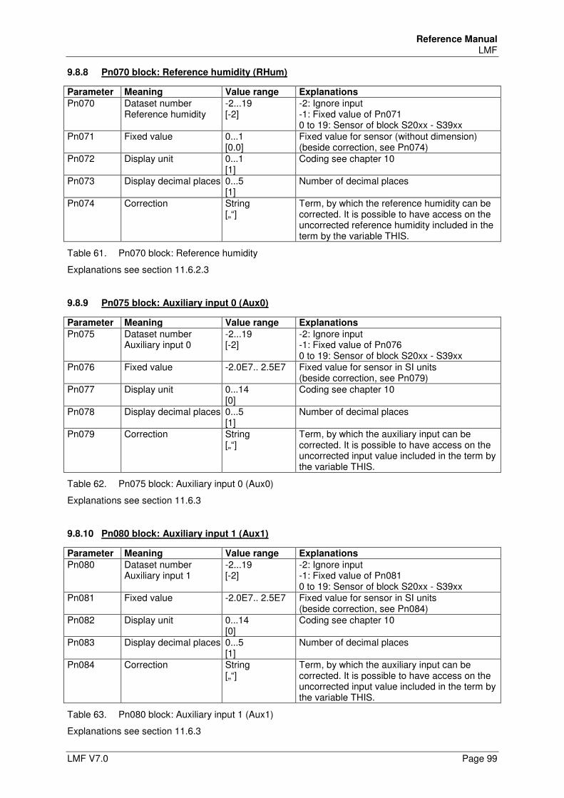
Reference Manual LMF
LMF V7.0 Page 99
9.8.8 Pn070 block: Reference humidity (RHum)
Parameter Meaning Value range Explanations
Pn070 Dataset number Reference humidity
-2...19 [-2]
-2: Ignore input -1: Fixed value of Pn071 0 to 19: Sensor of block S20xx - S39xx
Pn071 Fixed value 0...1 [0.0]
Fixed value for sensor (without dimension) (beside correction, see Pn074)
Pn072 Display unit 0...1 [1]
Coding see chapter 10
Pn073 Display decimal places 0...5 [1]
Number of decimal places
Pn074 Correction String [„“]
Term, by which the reference humidity can be corrected. It is possible to have access on the uncorrected reference humidity included in the term by the variable THIS.
Table 61. Pn070 block: Reference humidity
Explanations see section 11.6.2.3
9.8.9 Pn075 block: Auxiliary input 0 (Aux0)
Parameter Meaning Value range Explanations
Pn075 Dataset number Auxiliary input 0
-2...19 [-2]
-2: Ignore input -1: Fixed value of Pn076 0 to 19: Sensor of block S20xx - S39xx
Pn076 Fixed value -2.0E7.. 2.5E7 Fixed value for sensor in SI units (beside correction, see Pn079)
Pn077 Display unit 0...14 [0]
Coding see chapter 10
Pn078 Display decimal places 0...5 [1]
Number of decimal places
Pn079 Correction String [„“]
Term, by which the auxiliary input can be corrected. It is possible to have access on the uncorrected input value included in the term by the variable THIS.
Table 62. Pn075 block: Auxiliary input 0 (Aux0)
Explanations see section 11.6.3
9.8.10 Pn080 block: Auxiliary input 1 (Aux1)
Parameter Meaning Value range Explanations
Pn080 Dataset number Auxiliary input 1
-2...19 [-2]
-2: Ignore input -1: Fixed value of Pn081 0 to 19: Sensor of block S20xx - S39xx
Pn081 Fixed value -2.0E7.. 2.5E7 Fixed value for sensor in SI units (beside correction, see Pn084)
Pn082 Display unit 0...14 [0]
Coding see chapter 10
Pn083 Display decimal places 0...5 [1]
Number of decimal places
Pn084 Correction String [„“]
Term, by which the auxiliary input can be corrected. It is possible to have access on the uncorrected input value included in the term by the variable THIS.
Table 63. Pn080 block: Auxiliary input 1 (Aux1)
Explanations see section 11.6.3
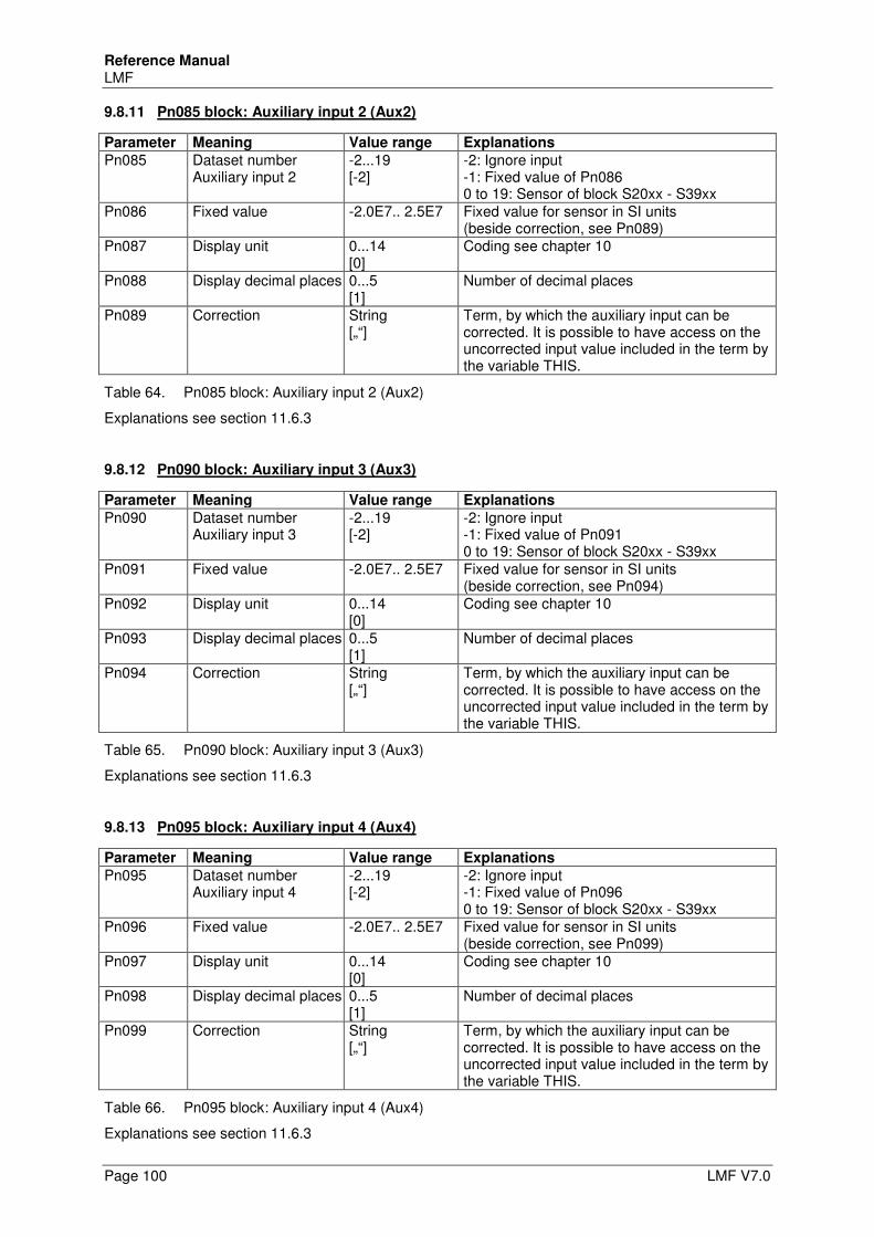
Reference Manual LMF
Page 100 LMF V7.0
9.8.11 Pn085 block: Auxiliary input 2 (Aux2)
Parameter Meaning Value range Explanations
Pn085 Dataset number Auxiliary input 2
-2...19 [-2]
-2: Ignore input -1: Fixed value of Pn086 0 to 19: Sensor of block S20xx - S39xx
Pn086 Fixed value -2.0E7.. 2.5E7 Fixed value for sensor in SI units (beside correction, see Pn089)
Pn087 Display unit 0...14 [0]
Coding see chapter 10
Pn088 Display decimal places 0...5 [1]
Number of decimal places
Pn089 Correction String [„“]
Term, by which the auxiliary input can be corrected. It is possible to have access on the uncorrected input value included in the term by the variable THIS.
Table 64. Pn085 block: Auxiliary input 2 (Aux2)
Explanations see section 11.6.3
9.8.12 Pn090 block: Auxiliary input 3 (Aux3)
Parameter Meaning Value range Explanations
Pn090 Dataset number Auxiliary input 3
-2...19 [-2]
-2: Ignore input -1: Fixed value of Pn091 0 to 19: Sensor of block S20xx - S39xx
Pn091 Fixed value -2.0E7.. 2.5E7 Fixed value for sensor in SI units (beside correction, see Pn094)
Pn092 Display unit 0...14 [0]
Coding see chapter 10
Pn093 Display decimal places 0...5 [1]
Number of decimal places
Pn094 Correction String [„“]
Term, by which the auxiliary input can be corrected. It is possible to have access on the uncorrected input value included in the term by the variable THIS.
Table 65. Pn090 block: Auxiliary input 3 (Aux3)
Explanations see section 11.6.3
9.8.13 Pn095 block: Auxiliary input 4 (Aux4)
Parameter Meaning Value range Explanations
Pn095 Dataset number Auxiliary input 4
-2...19 [-2]
-2: Ignore input -1: Fixed value of Pn096 0 to 19: Sensor of block S20xx - S39xx
Pn096 Fixed value -2.0E7.. 2.5E7 Fixed value for sensor in SI units (beside correction, see Pn099)
Pn097 Display unit 0...14 [0]
Coding see chapter 10
Pn098 Display decimal places 0...5 [1]
Number of decimal places
Pn099 Correction String [„“]
Term, by which the auxiliary input can be corrected. It is possible to have access on the uncorrected input value included in the term by the variable THIS.
Table 66. Pn095 block: Auxiliary input 4 (Aux4)
Explanations see section 11.6.3
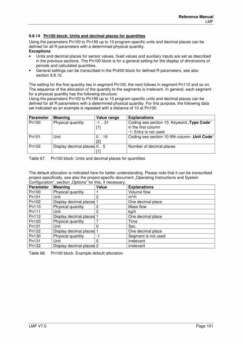
Reference Manual LMF
LMF V7.0 Page 101
9.8.14 Pn100 block: Units and decimal places for quantities
Using the parameters Pn100 to Pn199 up to 10 program-specific units and decimal places can be defined for all R parameters with a determined physical quantity. Exceptions
• Units and decimal places for sensor values, fixed values and auxiliary inputs are set as described in the previous sections. The Pn100 block is for a general setting for the display of dimensions of periods and calculated quantities.
• General settings can be transcribed in the Pn200 block for defined R parameters, see also section 9.8.15.
The setting for the first quantity lies in segment Pn100, the next follows in segment Pn110 and so on. The sequence of the allocation of the quantity to the segments is irrelevant. In general, each segment for a physical quantity has the following structure: Using the parameters Pn100 to Pn199 up to 10 program-specific units and decimal places can be defined for all R parameters with a determined physical quantity. For this purpose, the following data set indicated as an example is repeated with a distance of 10 at Pn100. Parameter Meaning Value range Explanations
Pn100 Physical quantity -1 .. 21 [1]
Coding see section 10. Keyword „Type Code“ in the first column -1: Entry is not used
Pn101 Unit 0 .. 19 [2]
Coding see section 10 fifth column „Unit Code“
Pn102 Display decimal places 0 .. 5 [1]
Number of decimal places
Table 67. Pn100 block: Units and decimal places for quantities
The default allocation is indicated here for better understanding. Please note that it can be transcribed project-specifically, see also the project-specific document „Operating Instructions and System Configuration“, section „Options“ for this, if necessary. Parameter Meaning Value Explanations
Pn100 Physical quantity 1 Volume flow Pn101 Unit 2 m³/h Pn102 Display decimal places 1 One decimal place Pn110 Physical quantity 2 Mass flow Pn111 Unit 2 kg/h Pn112 Display decimal places 1 One decimal place Pn120 Physical quantity 7 Time Pn121 Unit 0 Sec. Pn122 Display decimal places 1 One decimal place Pn130 Physical quantity -1 Segment is not used Pn131 Unit 0 irrelevant Pn132 Display decimal places 2 irrelevant
Table 68. Pn100 block: Example default allocation
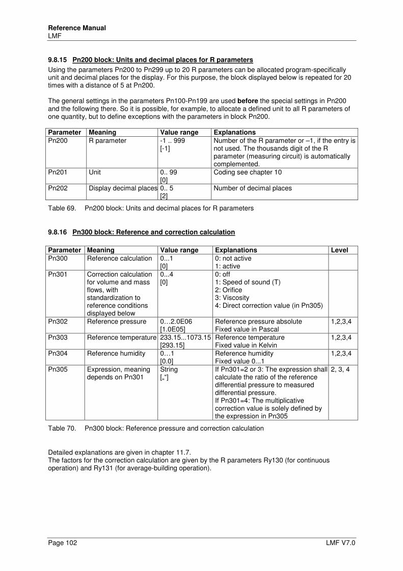
Reference Manual LMF
Page 102 LMF V7.0
9.8.15 Pn200 block: Units and decimal places for R parameters
Using the parameters Pn200 to Pn299 up to 20 R parameters can be allocated program-specifically unit and decimal places for the display. For this purpose, the block displayed below is repeated for 20 times with a distance of 5 at Pn200. The general settings in the parameters Pn100-Pn199 are used before the special settings in Pn200 and the following there. So it is possible, for example, to allocate a defined unit to all R parameters of one quantity, but to define exceptions with the parameters in block Pn200. Parameter Meaning Value range Explanations
Pn200 R parameter -1 .. 999 [-1]
Number of the R parameter or –1, if the entry is not used. The thousands digit of the R parameter (measuring circuit) is automatically complemented.
Pn201 Unit 0.. 99 [0]
Coding see chapter 10
Pn202 Display decimal places 0.. 5 [2]
Number of decimal places
Table 69. Pn200 block: Units and decimal places for R parameters
9.8.16 Pn300 block: Reference and correction calculation
Parameter Meaning Value range Explanations Level
Pn300 Reference calculation 0...1 [0]
0: not active 1: active
Pn301 Correction calculation for volume and mass flows, with standardization to reference conditions displayed below
0...4 [0]
0: off 1: Speed of sound (T) 2: Orifice 3: Viscosity 4: Direct correction value (in Pn305)
Pn302 Reference pressure 0…2.0E06 [1.0E05]
Reference pressure absolute Fixed value in Pascal
1,2,3,4
Pn303 Reference temperature 233.15...1073.15 [293.15]
Reference temperature Fixed value in Kelvin
1,2,3,4
Pn304 Reference humidity 0…1 [0.0]
Reference humidity Fixed value 0...1
1,2,3,4
Pn305 Expression, meaning depends on Pn301
String [„“]
If Pn301=2 or 3: The expression shall calculate the ratio of the reference differential pressure to measured differential pressure. If Pn301=4: The multiplicative correction value is solely defined by the expression in Pn305
2, 3, 4
Table 70. Pn300 block: Reference pressure and correction calculation
Detailed explanations are given in chapter 11.7. The factors for the correction calculation are given by the R parameters Ry130 (for continuous operation) and Ry131 (for average-building operation).
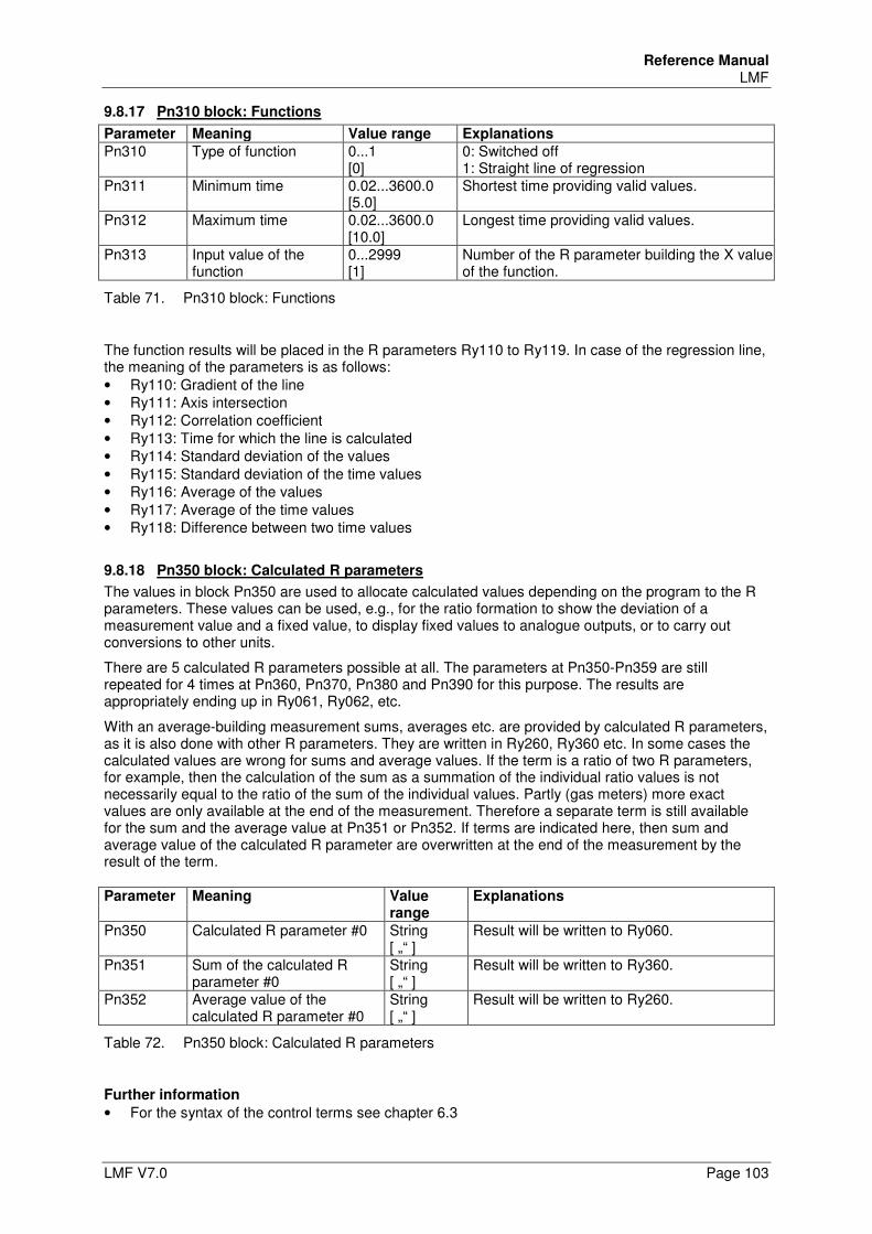
Reference Manual LMF
LMF V7.0 Page 103
9.8.17 Pn310 block: Functions
Parameter Meaning Value range Explanations
Pn310 Type of function 0...1 [0]
0: Switched off 1: Straight line of regression
Pn311 Minimum time 0.02...3600.0 [5.0]
Shortest time providing valid values.
Pn312 Maximum time 0.02...3600.0 [10.0]
Longest time providing valid values.
Pn313 Input value of the function
0...2999 [1]
Number of the R parameter building the X value of the function.
Table 71. Pn310 block: Functions
The function results will be placed in the R parameters Ry110 to Ry119. In case of the regression line, the meaning of the parameters is as follows: • Ry110: Gradient of the line • Ry111: Axis intersection • Ry112: Correlation coefficient • Ry113: Time for which the line is calculated • Ry114: Standard deviation of the values • Ry115: Standard deviation of the time values • Ry116: Average of the values • Ry117: Average of the time values • Ry118: Difference between two time values
9.8.18 Pn350 block: Calculated R parameters
The values in block Pn350 are used to allocate calculated values depending on the program to the R parameters. These values can be used, e.g., for the ratio formation to show the deviation of a measurement value and a fixed value, to display fixed values to analogue outputs, or to carry out conversions to other units.
There are 5 calculated R parameters possible at all. The parameters at Pn350-Pn359 are still repeated for 4 times at Pn360, Pn370, Pn380 and Pn390 for this purpose. The results are appropriately ending up in Ry061, Ry062, etc.
With an average-building measurement sums, averages etc. are provided by calculated R parameters, as it is also done with other R parameters. They are written in Ry260, Ry360 etc. In some cases the calculated values are wrong for sums and average values. If the term is a ratio of two R parameters, for example, then the calculation of the sum as a summation of the individual ratio values is not necessarily equal to the ratio of the sum of the individual values. Partly (gas meters) more exact values are only available at the end of the measurement. Therefore a separate term is still available for the sum and the average value at Pn351 or Pn352. If terms are indicated here, then sum and average value of the calculated R parameter are overwritten at the end of the measurement by the result of the term. Parameter Meaning Value
range Explanations
Pn350 Calculated R parameter #0 String [ „“ ]
Result will be written to Ry060.
Pn351 Sum of the calculated R parameter #0
String [ „“ ]
Result will be written to Ry360.
Pn352 Average value of the calculated R parameter #0
String [ „“ ]
Result will be written to Ry260.
Table 72. Pn350 block: Calculated R parameters
Further information
• For the syntax of the control terms see chapter 6.3
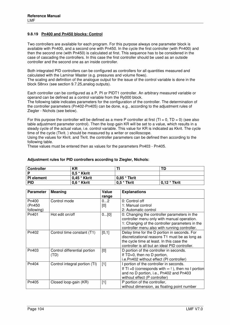
Reference Manual LMF
Page 104 LMF V7.0
9.8.19 Pn400 and Pn450 blocks: Control
Two controllers are available for each program. For this purpose always one parameter block is available with Pn400, and a second one with Pn450. In the cycle the first controller (with Pn400) and then the second one (with Pn450) is calculated at first. This sequence has to be considered in the case of cascading the controllers. In this case the first controller should be used as an outside controller and the second one as an inside controller. Both integrated PID controllers can be configured as controllers for all quantities measured and calculated with the Laminar Master (e.g. pressures and volume flows). The scaling and definition of the analogue output for the issue of the control variable is done in the block S8nxx (see section 9.7.25,analog outputs). Each controller can be configured as a P, PI or PIDT1 controller. An arbitrary measured variable or operand can be defined as a control variable from the Ry000 block. The following table indicates parameters for the configuration of the controller. The determination of the controller parameters (Pn402-Pn405) can be done, e.g., according to the adjustment rules of Ziegler - Nichols (see below). For this purpose the controller will be defined as a mere P controller at first (TI = 0, TD = 0) (see also table adjustment parameter control). Then the loop gain KR will be set to a value, which results in a steady cycle of the actual value, i.e. control variable. This value for KR is indicated as Kkrit. The cycle time of the cycle (Tkrit. ) should be measured by a writer or oscilloscope. Using the values for Kkrit. and Tkrit. the controller parameters can be defined then according to the following table. These values must be entered then as values for the parameters Pn403 - Pn405. Adjustment rules for PID controllers according to Ziegler, Nichols:
Controller KR TI TD
P 0,5 * Kkrit
PI element 0,45 * Kkrit 0,85 * Tkrit
PID 0,6 * Kkrit 0,5 * Tkrit 0,12 * Tkrit
Parameter Meaning Value range
Explanations
Pn400 (Pn450 following)
Control mode 0...2 [0]
0: Control off 1: Manual control 2: Automatic control
Pn401 Hot edit on/off 0...[0] 0: Changing the controller parameters in the controller menu only with manual operation. 1: Changing of the controller parameters in the controller menu also with running controller.
Pn402 Control time constant (T1) [0,1] Delay time for the D portion in seconds. For discretizational reasons T1 must be as long as the cycle time at least. In this case the controller is all but an ideal PID controller.
Pn403 Control differential portion (TD)
[0] D portion of the controller in seconds. If TD=0, then no D portion, i.e.Pn402 without effect (PI controller)
Pn404 Control integral portion (TI) [1] I portion of the controller in seconds. If TI =0 (corresponds with ∞ ! ), then no I portion and no D portion, i.e., Pn402 and Pn403 without effect (P controller)
Pn405 Closed loop-gain (KR) [1] P portion of the controller, without dimension, as floating point number
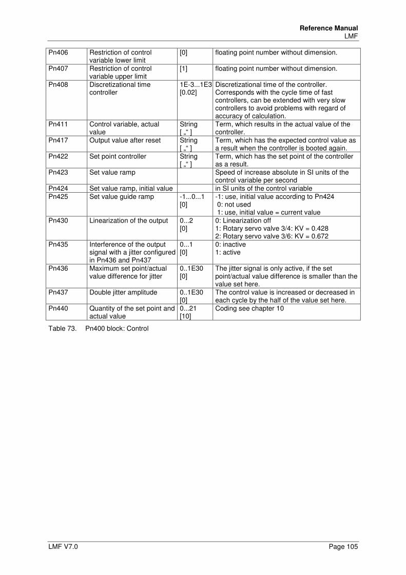
Reference Manual LMF
LMF V7.0 Page 105
Pn406 Restriction of control variable lower limit
[0] floating point number without dimension.
Pn407 Restriction of control variable upper limit
[1] floating point number without dimension.
Pn408 Discretizational time controller
1E-3...1E3 [0.02]
Discretizational time of the controller. Corresponds with the cycle time of fast controllers, can be extended with very slow controllers to avoid problems with regard of accuracy of calculation.
Pn411 Control variable, actual value
String [ „“ ]
Term, which results in the actual value of the controller.
Pn417 Output value after reset String [ „“ ]
Term, which has the expected control value as a result when the controller is booted again.
Pn422 Set point controller String [ „“ ]
Term, which has the set point of the controller as a result.
Pn423 Set value ramp Speed of increase absolute in SI units of the control variable per second
Pn424 Set value ramp, initial value in SI units of the control variable Pn425 Set value guide ramp -1...0...1
[0] -1: use, initial value according to Pn424 0: not used 1: use, initial value = current value
Pn430 Linearization of the output 0...2 [0]
0: Linearization off 1: Rotary servo valve 3/4: KV = 0.428 2: Rotary servo valve 3/6: KV = 0.672
Pn435 Interference of the output signal with a jitter configured in Pn436 and Pn437
0...1 [0]
0: inactive 1: active
Pn436 Maximum set point/actual value difference for jitter
0..1E30 [0]
The jitter signal is only active, if the set point/actual value difference is smaller than the value set here.
Pn437 Double jitter amplitude 0..1E30 [0]
The control value is increased or decreased in each cycle by the half of the value set here.
Pn440 Quantity of the set point and actual value
0...21 [10]
Coding see chapter 10
Table 73. Pn400 block: Control
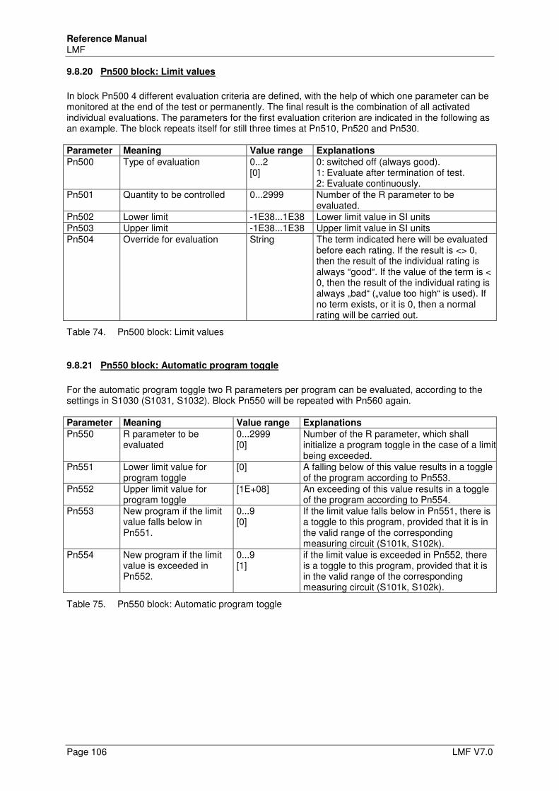
Reference Manual LMF
Page 106 LMF V7.0
9.8.20 Pn500 block: Limit values
In block Pn500 4 different evaluation criteria are defined, with the help of which one parameter can be monitored at the end of the test or permanently. The final result is the combination of all activated individual evaluations. The parameters for the first evaluation criterion are indicated in the following as an example. The block repeats itself for still three times at Pn510, Pn520 and Pn530. Parameter Meaning Value range Explanations
Pn500 Type of evaluation 0...2 [0]
0: switched off (always good). 1: Evaluate after termination of test. 2: Evaluate continuously.
Pn501 Quantity to be controlled 0...2999 Number of the R parameter to be evaluated.
Pn502 Lower limit -1E38...1E38 Lower limit value in SI units Pn503 Upper limit -1E38...1E38 Upper limit value in SI units Pn504 Override for evaluation String The term indicated here will be evaluated
before each rating. If the result is <> 0, then the result of the individual rating is always “good“. If the value of the term is < 0, then the result of the individual rating is always „bad“ („value too high“ is used). If no term exists, or it is 0, then a normal rating will be carried out.
Table 74. Pn500 block: Limit values
9.8.21 Pn550 block: Automatic program toggle
For the automatic program toggle two R parameters per program can be evaluated, according to the settings in S1030 (S1031, S1032). Block Pn550 will be repeated with Pn560 again. Parameter Meaning Value range Explanations
Pn550 R parameter to be evaluated
0...2999 [0]
Number of the R parameter, which shall initialize a program toggle in the case of a limit being exceeded.
Pn551 Lower limit value for program toggle
[0] A falling below of this value results in a toggle of the program according to Pn553.
Pn552 Upper limit value for program toggle
[1E+08] An exceeding of this value results in a toggle of the program according to Pn554.
Pn553 New program if the limit value falls below in Pn551.
0...9 [0]
If the limit value falls below in Pn551, there is a toggle to this program, provided that it is in the valid range of the corresponding measuring circuit (S101k, S102k).
Pn554 New program if the limit value is exceeded in Pn552.
0...9 [1]
if the limit value is exceeded in Pn552, there is a toggle to this program, provided that it is in the valid range of the corresponding measuring circuit (S101k, S102k).
Table 75. Pn550 block: Automatic program toggle
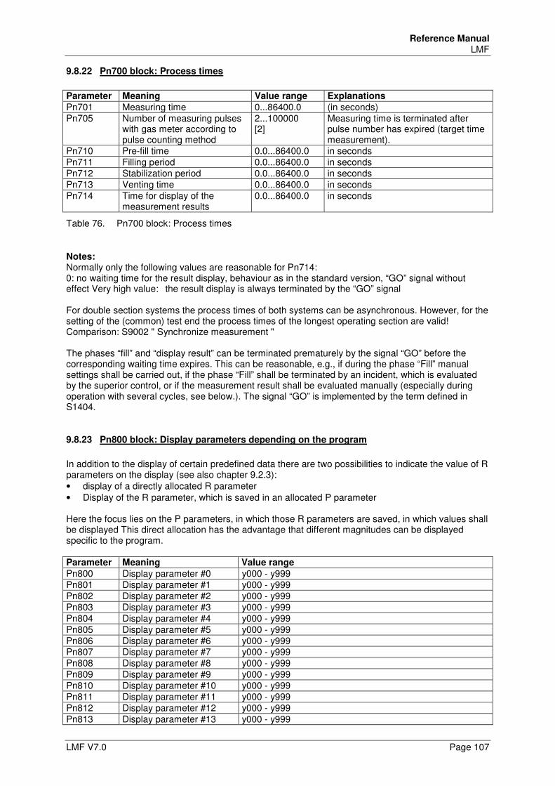
Reference Manual LMF
LMF V7.0 Page 107
9.8.22 Pn700 block: Process times
Parameter Meaning Value range Explanations
Pn701 Measuring time 0...86400.0 (in seconds) Pn705 Number of measuring pulses
with gas meter according to pulse counting method
2...100000 [2]
Measuring time is terminated after pulse number has expired (target time measurement).
Pn710 Pre-fill time 0.0...86400.0 in seconds Pn711 Filling period 0.0...86400.0 in seconds Pn712 Stabilization period 0.0...86400.0 in seconds Pn713 Venting time 0.0...86400.0 in seconds Pn714 Time for display of the
measurement results 0.0...86400.0 in seconds
Table 76. Pn700 block: Process times
Notes: Normally only the following values are reasonable for Pn714: 0: no waiting time for the result display, behaviour as in the standard version, “GO” signal without effect Very high value: the result display is always terminated by the “GO” signal For double section systems the process times of both systems can be asynchronous. However, for the setting of the (common) test end the process times of the longest operating section are valid! Comparison: S9002 " Synchronize measurement " The phases “fill” and “display result” can be terminated prematurely by the signal “GO” before the corresponding waiting time expires. This can be reasonable, e.g., if during the phase “Fill” manual settings shall be carried out, if the phase “Fill” shall be terminated by an incident, which is evaluated by the superior control, or if the measurement result shall be evaluated manually (especially during operation with several cycles, see below.). The signal “GO” is implemented by the term defined in S1404.
9.8.23 Pn800 block: Display parameters depending on the program
In addition to the display of certain predefined data there are two possibilities to indicate the value of R parameters on the display (see also chapter 9.2.3): • display of a directly allocated R parameter • Display of the R parameter, which is saved in an allocated P parameter Here the focus lies on the P parameters, in which those R parameters are saved, in which values shall be displayed This direct allocation has the advantage that different magnitudes can be displayed specific to the program. Parameter Meaning Value range
Pn800 Display parameter #0 y000 - y999 Pn801 Display parameter #1 y000 - y999 Pn802 Display parameter #2 y000 - y999 Pn803 Display parameter #3 y000 - y999 Pn804 Display parameter #4 y000 - y999 Pn805 Display parameter #5 y000 - y999 Pn806 Display parameter #6 y000 - y999 Pn807 Display parameter #7 y000 - y999 Pn808 Display parameter #8 y000 - y999 Pn809 Display parameter #9 y000 - y999 Pn810 Display parameter #10 y000 - y999 Pn811 Display parameter #11 y000 - y999 Pn812 Display parameter #12 y000 - y999 Pn813 Display parameter #13 y000 - y999
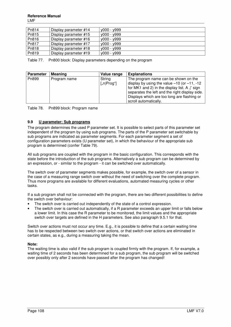
Reference Manual LMF
Page 108 LMF V7.0
Pn814 Display parameter #14 y000 - y999 Pn815 Display parameter #15 y000 - y999 Pn816 Display parameter #16 y000 - y999 Pn817 Display parameter #17 y000 - y999 Pn818 Display parameter #18 y000 - y999 Pn819 Display parameter #19 y000 - y999
Table 77. Pn800 block: Display parameters depending on the program
Parameter Meaning Value range Explanations
Pn899 Program name String [„n|Prog“]
The program name can be shown on the display by using the value –10 (or –11, -12 for MK1 and 2) in the display list. A ‚|’ sign separates the left and the right display side. Displays which are too long are flashing or scroll automatically.
Table 78. Pn899 block: Program name
9.9 U parameter: Sub programs
The program determines the used P parameter set. It is possible to select parts of this parameter set independent of the program by using sub programs. The parts of the P parameter set switchable by sub programs are indicated as parameter segments. For each parameter segment a set of configuration parameters exists (U parameter set), in which the behaviour of the appropriate sub program is determined (confer Table 79). All sub programs are coupled with the program in the basic configuration. This corresponds with the state before the introduction of the sub programs. Alternatively a sub program can be determined by an expression, or - similar to the program - it can be switched over automatically. The switch over of parameter segments makes possible, for example, the switch over of a sensor in the case of a measuring range switch over without the need of switching over the complete program. Thus more programs are available for different evaluations, automated measuring cycles or other tasks. If a sub program shall not be connected with the program, there are two different possibilities to define the switch over behaviour: • The switch over is carried out independently of the state of a control expression. • The switch over is carried out automatically, if a R parameter exceeds an upper limit or falls below
a lower limit. In this case the R parameter to be monitored, the limit values and the appropriate switch over targets are defined in the H parameters. See also paragraph 9.5.1 for that.
Switch over actions must not occur any time. E.g., it is possible to define that a certain waiting time has to be respected between two switch over actions, or that switch over actions are eliminated in certain states, as e.g., during a measuring taking the mean. Note: The waiting time is also valid if the sub program is coupled firmly with the program. If, for example, a waiting time of 2 seconds has been determined for a sub program, the sub program will be switched over possibly only after 2 seconds have passed after the program has changed!
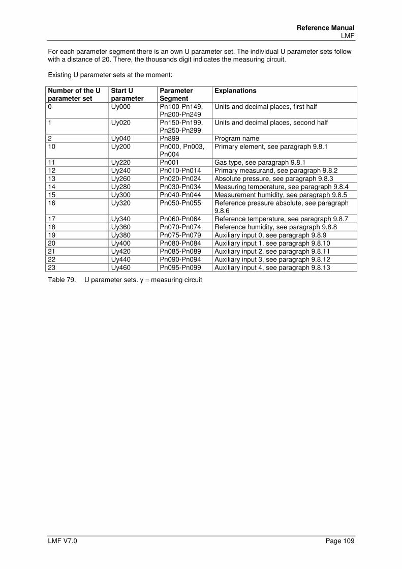
Reference Manual LMF
LMF V7.0 Page 109
For each parameter segment there is an own U parameter set. The individual U parameter sets follow with a distance of 20. There, the thousands digit indicates the measuring circuit. Existing U parameter sets at the moment: Number of the U parameter set
Start U parameter
Parameter Segment
Explanations
0 Uy000 Pn100-Pn149, Pn200-Pn249
Units and decimal places, first half
1 Uy020 Pn150-Pn199, Pn250-Pn299
Units and decimal places, second half
2 Uy040 Pn899 Program name 10 Uy200 Pn000, Pn003,
Pn004 Primary element, see paragraph 9.8.1
11 Uy220 Pn001 Gas type, see paragraph 9.8.1 12 Uy240 Pn010-Pn014 Primary measurand, see paragraph 9.8.2 13 Uy260 Pn020-Pn024 Absolute pressure, see paragraph 9.8.3 14 Uy280 Pn030-Pn034 Measuring temperature, see paragraph 9.8.4 15 Uy300 Pn040-Pn044 Measurement humidity, see paragraph 9.8.5 16 Uy320 Pn050-Pn055 Reference pressure absolute, see paragraph
9.8.6 17 Uy340 Pn060-Pn064 Reference temperature, see paragraph 9.8.7 18 Uy360 Pn070-Pn074 Reference humidity, see paragraph 9.8.8 19 Uy380 Pn075-Pn079 Auxiliary input 0, see paragraph 9.8.9 20 Uy400 Pn080-Pn084 Auxiliary input 1, see paragraph 9.8.10 21 Uy420 Pn085-Pn089 Auxiliary input 2, see paragraph 9.8.11 22 Uy440 Pn090-Pn094 Auxiliary input 3, see paragraph 9.8.12 23 Uy460 Pn095-Pn099 Auxiliary input 4, see paragraph 9.8.13
Table 79. U parameter sets. y = measuring circuit
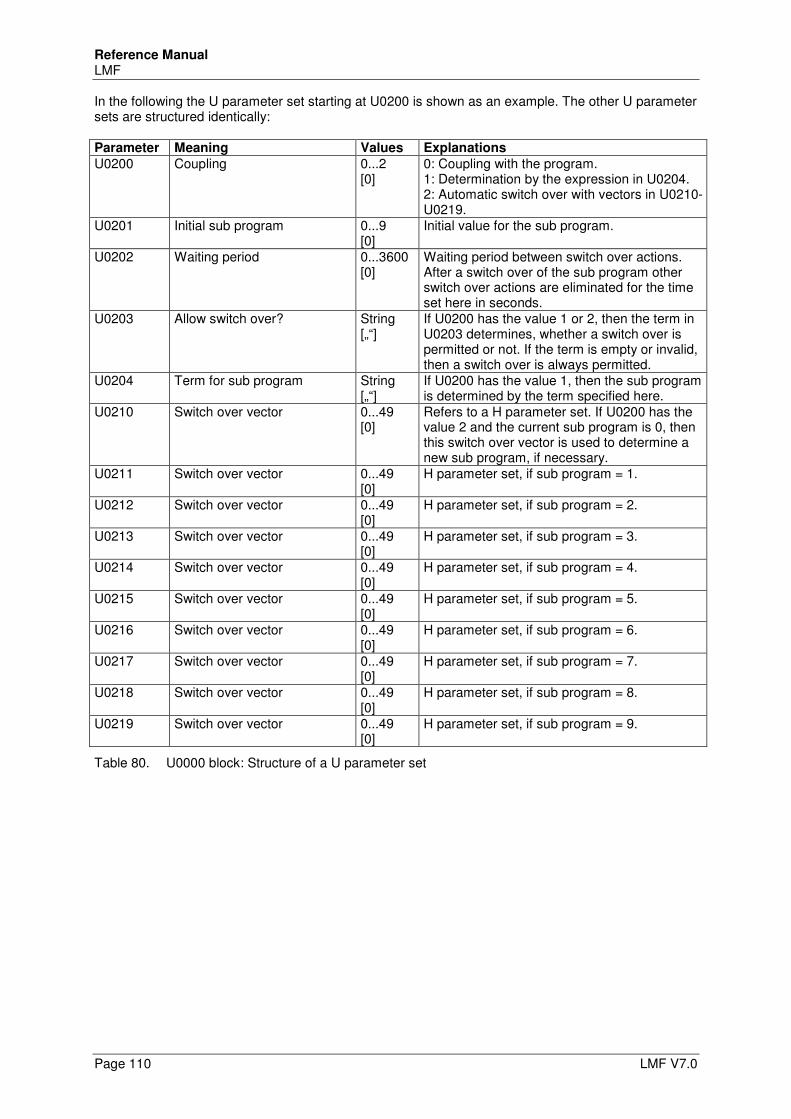
Reference Manual LMF
Page 110 LMF V7.0
In the following the U parameter set starting at U0200 is shown as an example. The other U parameter sets are structured identically:
Parameter Meaning Values Explanations
U0200 Coupling 0...2 [0]
0: Coupling with the program. 1: Determination by the expression in U0204. 2: Automatic switch over with vectors in U0210-U0219.
U0201 Initial sub program 0...9 [0]
Initial value for the sub program.
U0202 Waiting period 0...3600 [0]
Waiting period between switch over actions. After a switch over of the sub program other switch over actions are eliminated for the time set here in seconds.
U0203 Allow switch over? String [„“]
If U0200 has the value 1 or 2, then the term in U0203 determines, whether a switch over is permitted or not. If the term is empty or invalid, then a switch over is always permitted.
U0204 Term for sub program String [„“]
If U0200 has the value 1, then the sub program is determined by the term specified here.
U0210 Switch over vector 0...49 [0]
Refers to a H parameter set. If U0200 has the value 2 and the current sub program is 0, then this switch over vector is used to determine a new sub program, if necessary.
U0211 Switch over vector 0...49 [0]
H parameter set, if sub program = 1.
U0212 Switch over vector 0...49 [0]
H parameter set, if sub program = 2.
U0213 Switch over vector 0...49 [0]
H parameter set, if sub program = 3.
U0214 Switch over vector 0...49 [0]
H parameter set, if sub program = 4.
U0215 Switch over vector 0...49 [0]
H parameter set, if sub program = 5.
U0216 Switch over vector 0...49 [0]
H parameter set, if sub program = 6.
U0217 Switch over vector 0...49 [0]
H parameter set, if sub program = 7.
U0218 Switch over vector 0...49 [0]
H parameter set, if sub program = 8.
U0219 Switch over vector 0...49 [0]
H parameter set, if sub program = 9.
Table 80. U0000 block: Structure of a U parameter set
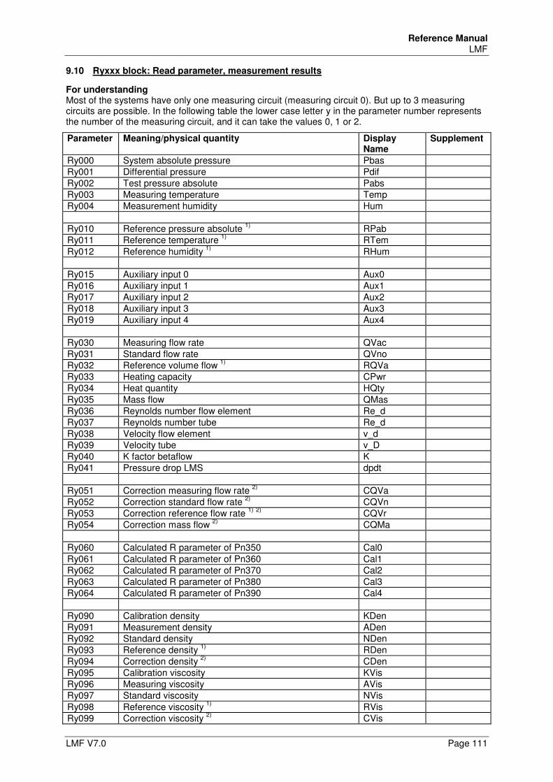
Reference Manual LMF
LMF V7.0 Page 111
9.10 Ryxxx block: Read parameter, measurement results
For understanding Most of the systems have only one measuring circuit (measuring circuit 0). But up to 3 measuring circuits are possible. In the following table the lower case letter y in the parameter number represents the number of the measuring circuit, and it can take the values 0, 1 or 2.
Parameter Meaning/physical quantity Display Name
Supplement
Ry000 System absolute pressure Pbas Ry001 Differential pressure Pdif Ry002 Test pressure absolute Pabs Ry003 Measuring temperature Temp Ry004 Measurement humidity Hum Ry010 Reference pressure absolute
1) RPab
Ry011 Reference temperature 1)
RTem Ry012 Reference humidity
1) RHum
Ry015 Auxiliary input 0 Aux0 Ry016 Auxiliary input 1 Aux1 Ry017 Auxiliary input 2 Aux2 Ry018 Auxiliary input 3 Aux3 Ry019 Auxiliary input 4 Aux4 Ry030 Measuring flow rate QVac Ry031 Standard flow rate QVno Ry032 Reference volume flow
1) RQVa
Ry033 Heating capacity CPwr Ry034 Heat quantity HQty Ry035 Mass flow QMas Ry036 Reynolds number flow element Re_d Ry037 Reynolds number tube Re_d Ry038 Velocity flow element v_d Ry039 Velocity tube v_D Ry040 K factor betaflow K Ry041 Pressure drop LMS dpdt Ry051 Correction measuring flow rate
2) CQVa
Ry052 Correction standard flow rate 2)
CQVn Ry053 Correction reference flow rate
1) 2)
CQVr Ry054 Correction mass flow
2) CQMa
Ry060 Calculated R parameter of Pn350 Cal0 Ry061 Calculated R parameter of Pn360 Cal1 Ry062 Calculated R parameter of Pn370 Cal2 Ry063 Calculated R parameter of Pn380 Cal3 Ry064 Calculated R parameter of Pn390 Cal4 Ry090 Calibration density KDen Ry091 Measurement density ADen Ry092 Standard density NDen Ry093 Reference density
1) RDen
Ry094 Correction density 2)
CDen Ry095 Calibration viscosity KVis Ry096 Measuring viscosity AVis Ry097 Standard viscosity NVis Ry098 Reference viscosity
1) RVis
Ry099 Correction viscosity 2)
CVis
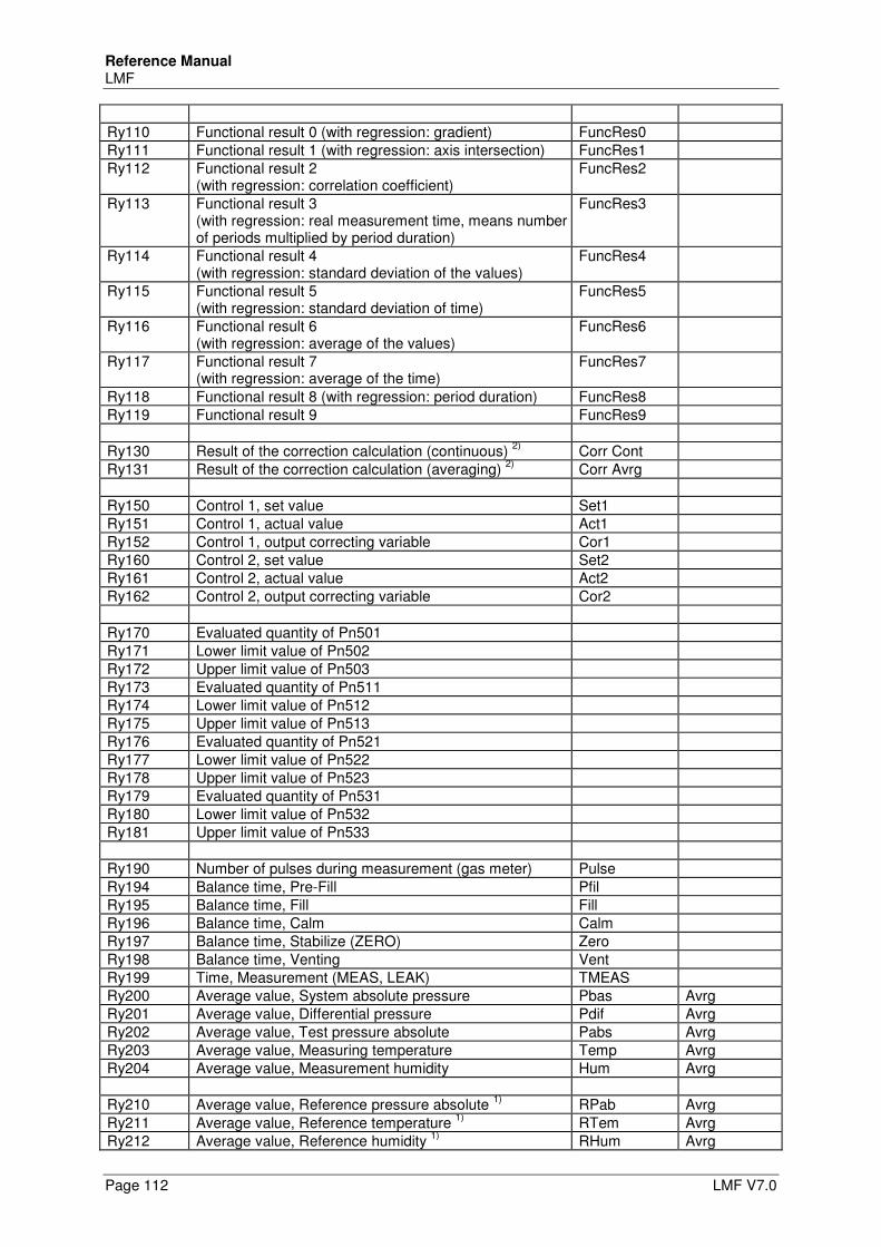
Reference Manual LMF
Page 112 LMF V7.0
Ry110 Functional result 0 (with regression: gradient) FuncRes0 Ry111 Functional result 1 (with regression: axis intersection) FuncRes1 Ry112 Functional result 2
(with regression: correlation coefficient) FuncRes2
Ry113 Functional result 3 (with regression: real measurement time, means number of periods multiplied by period duration)
FuncRes3
Ry114 Functional result 4 (with regression: standard deviation of the values)
FuncRes4
Ry115 Functional result 5 (with regression: standard deviation of time)
FuncRes5
Ry116 Functional result 6 (with regression: average of the values)
FuncRes6
Ry117 Functional result 7 (with regression: average of the time)
FuncRes7
Ry118 Functional result 8 (with regression: period duration) FuncRes8 Ry119 Functional result 9 FuncRes9 Ry130 Result of the correction calculation (continuous)
2) Corr Cont
Ry131 Result of the correction calculation (averaging) 2)
Corr Avrg Ry150 Control 1, set value Set1 Ry151 Control 1, actual value Act1 Ry152 Control 1, output correcting variable Cor1 Ry160 Control 2, set value Set2 Ry161 Control 2, actual value Act2 Ry162 Control 2, output correcting variable Cor2 Ry170 Evaluated quantity of Pn501 Ry171 Lower limit value of Pn502 Ry172 Upper limit value of Pn503 Ry173 Evaluated quantity of Pn511 Ry174 Lower limit value of Pn512 Ry175 Upper limit value of Pn513 Ry176 Evaluated quantity of Pn521 Ry177 Lower limit value of Pn522 Ry178 Upper limit value of Pn523 Ry179 Evaluated quantity of Pn531 Ry180 Lower limit value of Pn532 Ry181 Upper limit value of Pn533 Ry190 Number of pulses during measurement (gas meter) Pulse Ry194 Balance time, Pre-Fill Pfil Ry195 Balance time, Fill Fill Ry196 Balance time, Calm Calm Ry197 Balance time, Stabilize (ZERO) Zero Ry198 Balance time, Venting Vent Ry199 Time, Measurement (MEAS, LEAK) TMEAS Ry200 Average value, System absolute pressure Pbas Avrg Ry201 Average value, Differential pressure Pdif Avrg Ry202 Average value, Test pressure absolute Pabs Avrg Ry203 Average value, Measuring temperature Temp Avrg Ry204 Average value, Measurement humidity Hum Avrg Ry210 Average value, Reference pressure absolute
1) RPab Avrg
Ry211 Average value, Reference temperature 1)
RTem Avrg Ry212 Average value, Reference humidity
1) RHum Avrg
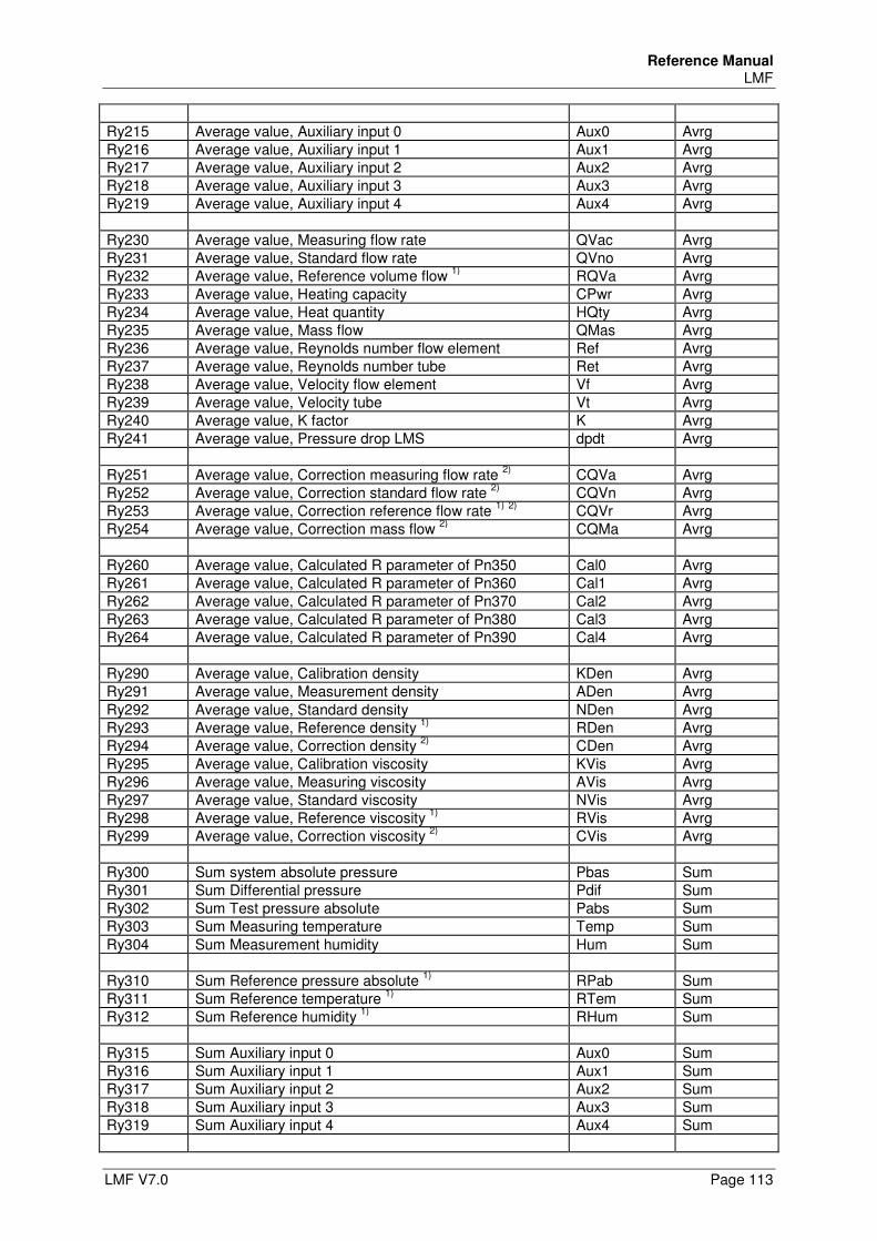
Reference Manual LMF
LMF V7.0 Page 113
Ry215 Average value, Auxiliary input 0 Aux0 Avrg Ry216 Average value, Auxiliary input 1 Aux1 Avrg Ry217 Average value, Auxiliary input 2 Aux2 Avrg Ry218 Average value, Auxiliary input 3 Aux3 Avrg Ry219 Average value, Auxiliary input 4 Aux4 Avrg Ry230 Average value, Measuring flow rate QVac Avrg Ry231 Average value, Standard flow rate QVno Avrg Ry232 Average value, Reference volume flow
1) RQVa Avrg
Ry233 Average value, Heating capacity CPwr Avrg Ry234 Average value, Heat quantity HQty Avrg Ry235 Average value, Mass flow QMas Avrg Ry236 Average value, Reynolds number flow element Ref Avrg Ry237 Average value, Reynolds number tube Ret Avrg Ry238 Average value, Velocity flow element Vf Avrg Ry239 Average value, Velocity tube Vt Avrg Ry240 Average value, K factor K Avrg Ry241 Average value, Pressure drop LMS dpdt Avrg Ry251 Average value, Correction measuring flow rate
2) CQVa Avrg
Ry252 Average value, Correction standard flow rate 2)
CQVn Avrg Ry253 Average value, Correction reference flow rate
1) 2)
CQVr Avrg Ry254 Average value, Correction mass flow
2) CQMa Avrg
Ry260 Average value, Calculated R parameter of Pn350 Cal0 Avrg Ry261 Average value, Calculated R parameter of Pn360 Cal1 Avrg Ry262 Average value, Calculated R parameter of Pn370 Cal2 Avrg Ry263 Average value, Calculated R parameter of Pn380 Cal3 Avrg Ry264 Average value, Calculated R parameter of Pn390 Cal4 Avrg Ry290 Average value, Calibration density KDen Avrg Ry291 Average value, Measurement density ADen Avrg Ry292 Average value, Standard density NDen Avrg Ry293 Average value, Reference density
1) RDen Avrg
Ry294 Average value, Correction density 2)
CDen Avrg Ry295 Average value, Calibration viscosity KVis Avrg Ry296 Average value, Measuring viscosity AVis Avrg Ry297 Average value, Standard viscosity NVis Avrg Ry298 Average value, Reference viscosity
1) RVis Avrg
Ry299 Average value, Correction viscosity 2)
CVis Avrg Ry300 Sum system absolute pressure Pbas Sum Ry301 Sum Differential pressure Pdif Sum Ry302 Sum Test pressure absolute Pabs Sum Ry303 Sum Measuring temperature Temp Sum Ry304 Sum Measurement humidity Hum Sum Ry310 Sum Reference pressure absolute
1) RPab Sum
Ry311 Sum Reference temperature 1)
RTem Sum Ry312 Sum Reference humidity
1) RHum Sum
Ry315 Sum Auxiliary input 0 Aux0 Sum Ry316 Sum Auxiliary input 1 Aux1 Sum Ry317 Sum Auxiliary input 2 Aux2 Sum Ry318 Sum Auxiliary input 3 Aux3 Sum Ry319 Sum Auxiliary input 4 Aux4 Sum
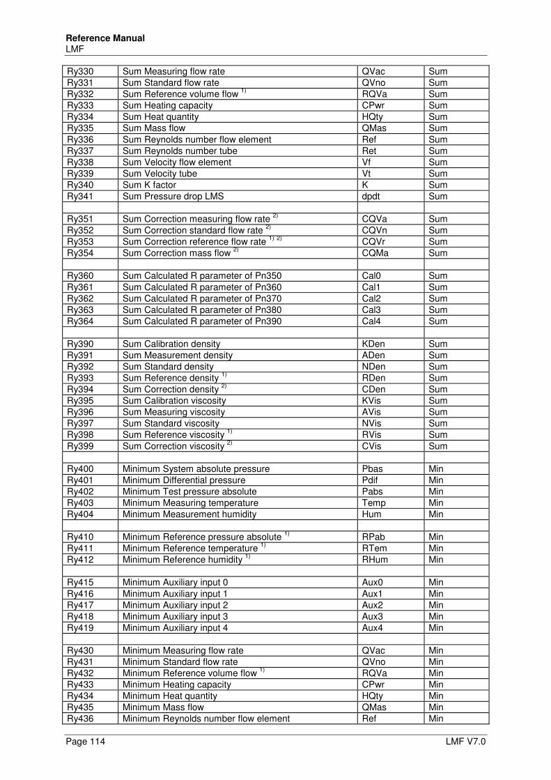
Reference Manual LMF
Page 114 LMF V7.0
Ry330 Sum Measuring flow rate QVac Sum Ry331 Sum Standard flow rate QVno Sum Ry332 Sum Reference volume flow
1) RQVa Sum
Ry333 Sum Heating capacity CPwr Sum Ry334 Sum Heat quantity HQty Sum Ry335 Sum Mass flow QMas Sum Ry336 Sum Reynolds number flow element Ref Sum Ry337 Sum Reynolds number tube Ret Sum Ry338 Sum Velocity flow element Vf Sum Ry339 Sum Velocity tube Vt Sum Ry340 Sum K factor K Sum Ry341 Sum Pressure drop LMS dpdt Sum Ry351 Sum Correction measuring flow rate
2) CQVa Sum
Ry352 Sum Correction standard flow rate 2)
CQVn Sum Ry353 Sum Correction reference flow rate
1) 2)
CQVr Sum Ry354 Sum Correction mass flow
2) CQMa Sum
Ry360 Sum Calculated R parameter of Pn350 Cal0 Sum Ry361 Sum Calculated R parameter of Pn360 Cal1 Sum Ry362 Sum Calculated R parameter of Pn370 Cal2 Sum Ry363 Sum Calculated R parameter of Pn380 Cal3 Sum Ry364 Sum Calculated R parameter of Pn390 Cal4 Sum Ry390 Sum Calibration density KDen Sum Ry391 Sum Measurement density ADen Sum Ry392 Sum Standard density NDen Sum Ry393 Sum Reference density
1) RDen Sum
Ry394 Sum Correction density 2)
CDen Sum Ry395 Sum Calibration viscosity KVis Sum Ry396 Sum Measuring viscosity AVis Sum Ry397 Sum Standard viscosity NVis Sum Ry398 Sum Reference viscosity
1) RVis Sum
Ry399 Sum Correction viscosity 2)
CVis Sum Ry400 Minimum System absolute pressure Pbas Min Ry401 Minimum Differential pressure Pdif Min Ry402 Minimum Test pressure absolute Pabs Min Ry403 Minimum Measuring temperature Temp Min Ry404 Minimum Measurement humidity Hum Min Ry410 Minimum Reference pressure absolute
1) RPab Min
Ry411 Minimum Reference temperature 1)
RTem Min Ry412 Minimum Reference humidity
1) RHum Min
Ry415 Minimum Auxiliary input 0 Aux0 Min Ry416 Minimum Auxiliary input 1 Aux1 Min Ry417 Minimum Auxiliary input 2 Aux2 Min Ry418 Minimum Auxiliary input 3 Aux3 Min Ry419 Minimum Auxiliary input 4 Aux4 Min Ry430 Minimum Measuring flow rate QVac Min Ry431 Minimum Standard flow rate QVno Min Ry432 Minimum Reference volume flow
1) RQVa Min
Ry433 Minimum Heating capacity CPwr Min Ry434 Minimum Heat quantity HQty Min Ry435 Minimum Mass flow QMas Min Ry436 Minimum Reynolds number flow element Ref Min
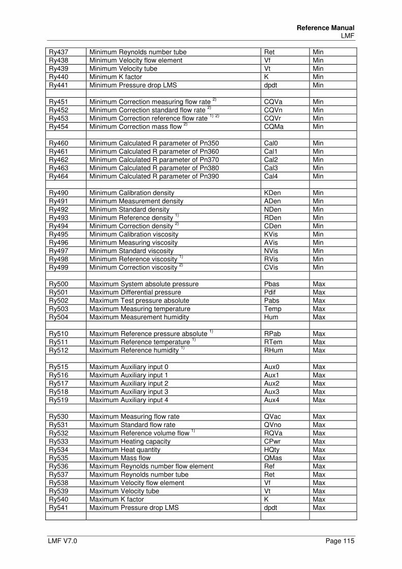
Reference Manual LMF
LMF V7.0 Page 115
Ry437 Minimum Reynolds number tube Ret Min Ry438 Minimum Velocity flow element Vf Min Ry439 Minimum Velocity tube Vt Min Ry440 Minimum K factor K Min Ry441 Minimum Pressure drop LMS dpdt Min Ry451 Minimum Correction measuring flow rate
2) CQVa Min
Ry452 Minimum Correction standard flow rate 2)
CQVn Min Ry453 Minimum Correction reference flow rate
1) 2)
CQVr Min Ry454 Minimum Correction mass flow
2) CQMa Min
Ry460 Minimum Calculated R parameter of Pn350 Cal0 Min Ry461 Minimum Calculated R parameter of Pn360 Cal1 Min Ry462 Minimum Calculated R parameter of Pn370 Cal2 Min Ry463 Minimum Calculated R parameter of Pn380 Cal3 Min Ry464 Minimum Calculated R parameter of Pn390 Cal4 Min Ry490 Minimum Calibration density KDen Min Ry491 Minimum Measurement density ADen Min Ry492 Minimum Standard density NDen Min Ry493 Minimum Reference density
1) RDen Min
Ry494 Minimum Correction density 2)
CDen Min Ry495 Minimum Calibration viscosity KVis Min Ry496 Minimum Measuring viscosity AVis Min Ry497 Minimum Standard viscosity NVis Min Ry498 Minimum Reference viscosity
1) RVis Min
Ry499 Minimum Correction viscosity 2)
CVis Min Ry500 Maximum System absolute pressure Pbas Max Ry501 Maximum Differential pressure Pdif Max Ry502 Maximum Test pressure absolute Pabs Max Ry503 Maximum Measuring temperature Temp Max Ry504 Maximum Measurement humidity Hum Max Ry510 Maximum Reference pressure absolute
1) RPab Max
Ry511 Maximum Reference temperature 1)
RTem Max Ry512 Maximum Reference humidity
1) RHum Max
Ry515 Maximum Auxiliary input 0 Aux0 Max Ry516 Maximum Auxiliary input 1 Aux1 Max Ry517 Maximum Auxiliary input 2 Aux2 Max Ry518 Maximum Auxiliary input 3 Aux3 Max Ry519 Maximum Auxiliary input 4 Aux4 Max Ry530 Maximum Measuring flow rate QVac Max Ry531 Maximum Standard flow rate QVno Max Ry532 Maximum Reference volume flow
1) RQVa Max
Ry533 Maximum Heating capacity CPwr Max Ry534 Maximum Heat quantity HQty Max Ry535 Maximum Mass flow QMas Max Ry536 Maximum Reynolds number flow element Ref Max Ry537 Maximum Reynolds number tube Ret Max Ry538 Maximum Velocity flow element Vf Max Ry539 Maximum Velocity tube Vt Max Ry540 Maximum K factor K Max Ry541 Maximum Pressure drop LMS dpdt Max
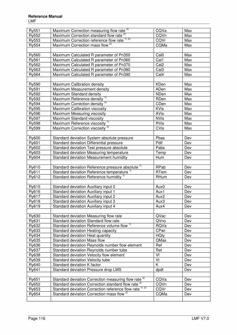
Reference Manual LMF
Page 116 LMF V7.0
Ry551 Maximum Correction measuring flow rate 2)
CQVa Max Ry552 Maximum Correction standard flow rate
2) CQVn Max
Ry553 Maximum Correction reference flow rate 1)
2)
CQVr Max Ry554 Maximum Correction mass flow
2) CQMa Max
Ry560 Maximum Calculated R parameter of Pn350 Cal0 Max Ry561 Maximum Calculated R parameter of Pn360 Cal1 Max Ry562 Maximum Calculated R parameter of Pn370 Cal2 Max Ry563 Maximum Calculated R parameter of Pn380 Cal3 Max Ry564 Maximum Calculated R parameter of Pn390 Cal4 Max Ry590 Maximum Calibration density KDen Max Ry591 Maximum Measurement density ADen Max Ry592 Maximum Standard density NDen Max Ry593 Maximum Reference density
1) RDen Max
Ry594 Maximum Correction density 2)
CDen Max Ry595 Maximum Calibration viscosity KVis Max Ry596 Maximum Measuring viscosity AVis Max Ry597 Maximum Standard viscosity NVis Max Ry598 Maximum Reference viscosity
1) RVis Max
Ry599 Maximum Correction viscosity 2)
CVis Max Ry600 Standard deviation System absolute pressure Pbas Dev Ry601 Standard deviation Differential pressure Pdif Dev Ry602 Standard deviation Test pressure absolute Pabs Dev Ry603 Standard deviation Measuring temperature Temp Dev Ry604 Standard deviation Measurement humidity Hum Dev Ry610 Standard deviation Reference pressure absolute
1) RPab Dev
Ry611 Standard deviation Reference temperature 1)
RTem Dev Ry612 Standard deviation Reference humidity
1) RHum Dev
Ry615 Standard deviation Auxiliary input 0 Aux0 Dev Ry616 Standard deviation Auxiliary input 1 Aux1 Dev Ry617 Standard deviation Auxiliary input 2 Aux2 Dev Ry618 Standard deviation Auxiliary input 3 Aux3 Dev Ry619 Standard deviation Auxiliary input 4 Aux4 Dev Ry630 Standard deviation Measuring flow rate QVac Dev Ry631 Standard deviation Standard flow rate QVno Dev Ry632 Standard deviation Reference volume flow
1) RQVa Dev
Ry633 Standard deviation Heating capacity CPwr Dev Ry634 Standard deviation Heat quantity HQty Dev Ry635 Standard deviation Mass flow QMas Dev Ry636 Standard deviation Reynolds number flow element Ref Dev Ry637 Standard deviation Reynolds number tube Ret Dev Ry638 Standard deviation Velocity flow element Vf Dev Ry639 Standard deviation Velocity tube Vt Dev Ry640 Standard deviation K factor K Dev Ry641 Standard deviation Pressure drop LMS dpdt Dev Ry651 Standard deviation Correction measuring flow rate
2) CQVa Dev
Ry652 Standard deviation Correction standard flow rate 2)
CQVn Dev Ry653 Standard deviation Correction reference flow rate
1) 2)
CQVr Dev Ry654 Standard deviation Correction mass flow
2) CQMa Dev
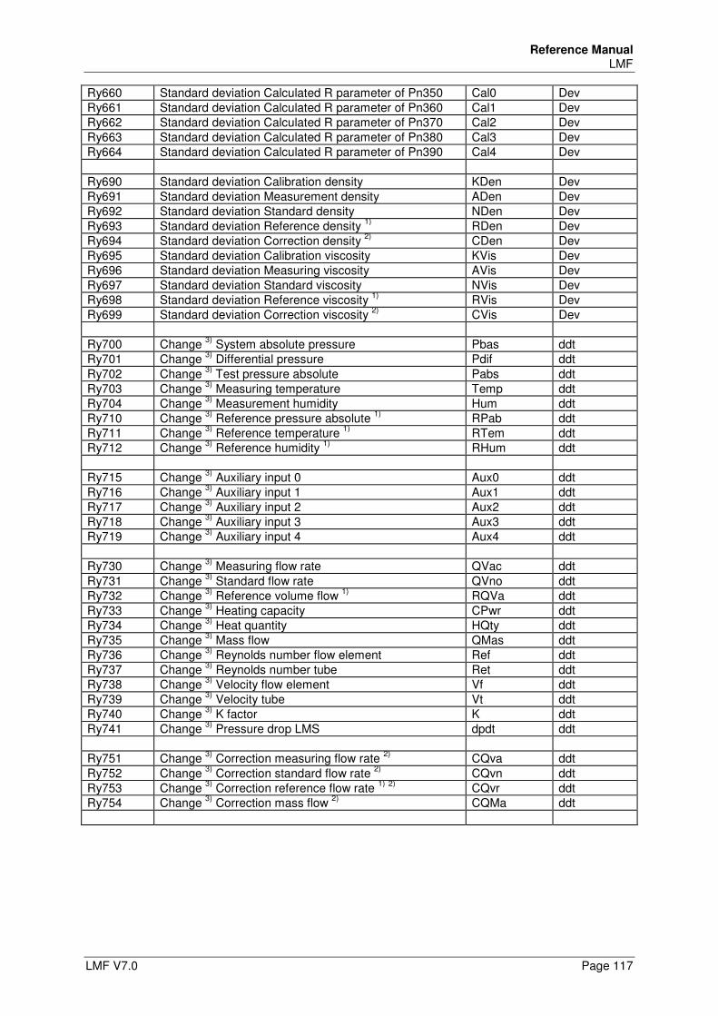
Reference Manual LMF
LMF V7.0 Page 117
Ry660 Standard deviation Calculated R parameter of Pn350 Cal0 Dev Ry661 Standard deviation Calculated R parameter of Pn360 Cal1 Dev Ry662 Standard deviation Calculated R parameter of Pn370 Cal2 Dev Ry663 Standard deviation Calculated R parameter of Pn380 Cal3 Dev Ry664 Standard deviation Calculated R parameter of Pn390 Cal4 Dev Ry690 Standard deviation Calibration density KDen Dev Ry691 Standard deviation Measurement density ADen Dev Ry692 Standard deviation Standard density NDen Dev Ry693 Standard deviation Reference density
1) RDen Dev
Ry694 Standard deviation Correction density 2)
CDen Dev Ry695 Standard deviation Calibration viscosity KVis Dev Ry696 Standard deviation Measuring viscosity AVis Dev Ry697 Standard deviation Standard viscosity NVis Dev Ry698 Standard deviation Reference viscosity
1) RVis Dev
Ry699 Standard deviation Correction viscosity 2)
CVis Dev Ry700 Change
3) System absolute pressure Pbas ddt
Ry701 Change 3)
Differential pressure Pdif ddt Ry702 Change
3) Test pressure absolute Pabs ddt
Ry703 Change 3)
Measuring temperature Temp ddt Ry704 Change
3) Measurement humidity Hum ddt
Ry710 Change 3)
Reference pressure absolute 1)
RPab ddt Ry711 Change
3) Reference temperature
1) RTem ddt
Ry712 Change 3)
Reference humidity 1)
RHum ddt Ry715 Change
3) Auxiliary input 0 Aux0 ddt
Ry716 Change 3)
Auxiliary input 1 Aux1 ddt Ry717 Change
3) Auxiliary input 2 Aux2 ddt
Ry718 Change 3)
Auxiliary input 3 Aux3 ddt Ry719 Change
3) Auxiliary input 4 Aux4 ddt
Ry730 Change
3) Measuring flow rate QVac ddt
Ry731 Change 3)
Standard flow rate QVno ddt Ry732 Change
3) Reference volume flow
1) RQVa ddt
Ry733 Change 3)
Heating capacity CPwr ddt Ry734 Change
3) Heat quantity HQty ddt
Ry735 Change 3)
Mass flow QMas ddt Ry736 Change
3) Reynolds number flow element Ref ddt
Ry737 Change 3)
Reynolds number tube Ret ddt Ry738 Change
3) Velocity flow element Vf ddt
Ry739 Change 3)
Velocity tube Vt ddt Ry740 Change
3) K factor K ddt
Ry741 Change 3)
Pressure drop LMS dpdt ddt Ry751 Change
3) Correction measuring flow rate
2) CQva ddt
Ry752 Change 3)
Correction standard flow rate 2)
CQvn ddt Ry753 Change
3) Correction reference flow rate
1) 2)
CQvr ddt Ry754 Change
3) Correction mass flow
2) CQMa ddt
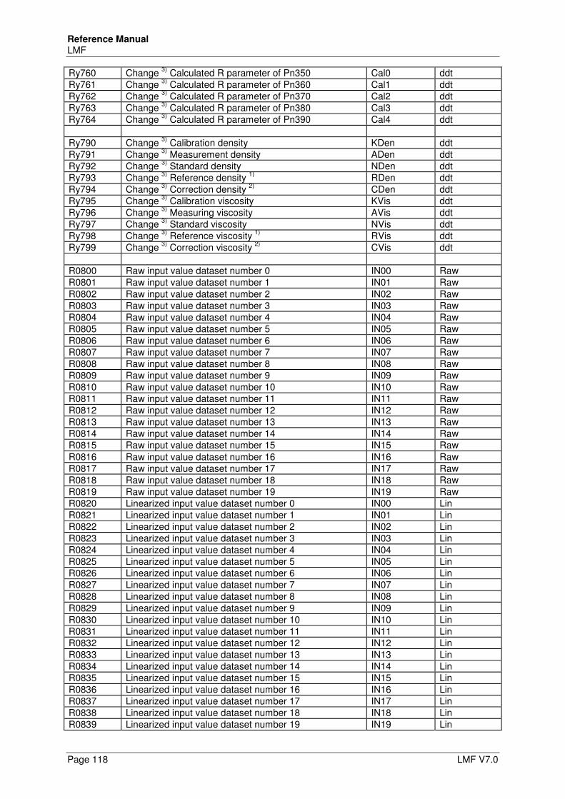
Reference Manual LMF
Page 118 LMF V7.0
Ry760 Change 3)
Calculated R parameter of Pn350 Cal0 ddt Ry761 Change
3) Calculated R parameter of Pn360 Cal1 ddt
Ry762 Change 3)
Calculated R parameter of Pn370 Cal2 ddt Ry763 Change
3) Calculated R parameter of Pn380 Cal3 ddt
Ry764 Change 3)
Calculated R parameter of Pn390 Cal4 ddt Ry790 Change
3) Calibration density KDen ddt
Ry791 Change 3)
Measurement density ADen ddt Ry792 Change
3) Standard density NDen ddt
Ry793 Change 3)
Reference density 1)
RDen ddt Ry794 Change
3) Correction density
2) CDen ddt
Ry795 Change 3)
Calibration viscosity KVis ddt Ry796 Change
3) Measuring viscosity AVis ddt
Ry797 Change 3)
Standard viscosity NVis ddt Ry798 Change
3) Reference viscosity
1) RVis ddt
Ry799 Change 3)
Correction viscosity 2)
CVis ddt R0800 Raw input value dataset number 0 IN00 Raw R0801 Raw input value dataset number 1 IN01 Raw R0802 Raw input value dataset number 2 IN02 Raw R0803 Raw input value dataset number 3 IN03 Raw R0804 Raw input value dataset number 4 IN04 Raw R0805 Raw input value dataset number 5 IN05 Raw R0806 Raw input value dataset number 6 IN06 Raw R0807 Raw input value dataset number 7 IN07 Raw R0808 Raw input value dataset number 8 IN08 Raw R0809 Raw input value dataset number 9 IN09 Raw R0810 Raw input value dataset number 10 IN10 Raw R0811 Raw input value dataset number 11 IN11 Raw R0812 Raw input value dataset number 12 IN12 Raw R0813 Raw input value dataset number 13 IN13 Raw R0814 Raw input value dataset number 14 IN14 Raw R0815 Raw input value dataset number 15 IN15 Raw R0816 Raw input value dataset number 16 IN16 Raw R0817 Raw input value dataset number 17 IN17 Raw R0818 Raw input value dataset number 18 IN18 Raw R0819 Raw input value dataset number 19 IN19 Raw R0820 Linearized input value dataset number 0 IN00 Lin R0821 Linearized input value dataset number 1 IN01 Lin R0822 Linearized input value dataset number 2 IN02 Lin R0823 Linearized input value dataset number 3 IN03 Lin R0824 Linearized input value dataset number 4 IN04 Lin R0825 Linearized input value dataset number 5 IN05 Lin R0826 Linearized input value dataset number 6 IN06 Lin R0827 Linearized input value dataset number 7 IN07 Lin R0828 Linearized input value dataset number 8 IN08 Lin R0829 Linearized input value dataset number 9 IN09 Lin R0830 Linearized input value dataset number 10 IN10 Lin R0831 Linearized input value dataset number 11 IN11 Lin R0832 Linearized input value dataset number 12 IN12 Lin R0833 Linearized input value dataset number 13 IN13 Lin R0834 Linearized input value dataset number 14 IN14 Lin R0835 Linearized input value dataset number 15 IN15 Lin R0836 Linearized input value dataset number 16 IN16 Lin R0837 Linearized input value dataset number 17 IN17 Lin R0838 Linearized input value dataset number 18 IN18 Lin R0839 Linearized input value dataset number 19 IN19 Lin
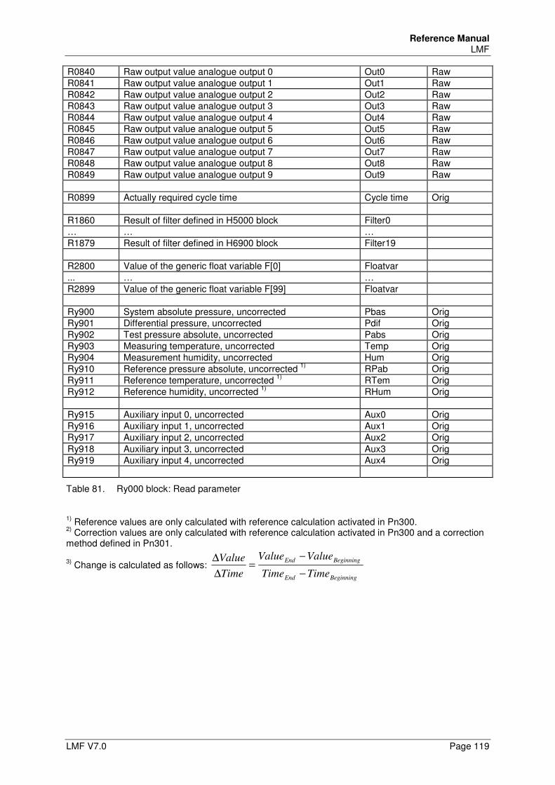
Reference Manual LMF
LMF V7.0 Page 119
R0840 Raw output value analogue output 0 Out0 Raw R0841 Raw output value analogue output 1 Out1 Raw R0842 Raw output value analogue output 2 Out2 Raw R0843 Raw output value analogue output 3 Out3 Raw R0844 Raw output value analogue output 4 Out4 Raw R0845 Raw output value analogue output 5 Out5 Raw R0846 Raw output value analogue output 6 Out6 Raw R0847 Raw output value analogue output 7 Out7 Raw R0848 Raw output value analogue output 8 Out8 Raw R0849 Raw output value analogue output 9 Out9 Raw R0899 Actually required cycle time Cycle time Orig R1860 Result of filter defined in H5000 block Filter0 … … … R1879 Result of filter defined in H6900 block Filter19 R2800 Value of the generic float variable F[0] Floatvar ... … … R2899 Value of the generic float variable F[99] Floatvar Ry900 System absolute pressure, uncorrected Pbas Orig Ry901 Differential pressure, uncorrected Pdif Orig Ry902 Test pressure absolute, uncorrected Pabs Orig Ry903 Measuring temperature, uncorrected Temp Orig Ry904 Measurement humidity, uncorrected Hum Orig Ry910 Reference pressure absolute, uncorrected
1) RPab Orig
Ry911 Reference temperature, uncorrected 1)
RTem Orig Ry912 Reference humidity, uncorrected
1) RHum Orig
Ry915 Auxiliary input 0, uncorrected Aux0 Orig Ry916 Auxiliary input 1, uncorrected Aux1 Orig Ry917 Auxiliary input 2, uncorrected Aux2 Orig Ry918 Auxiliary input 3, uncorrected Aux3 Orig Ry919 Auxiliary input 4, uncorrected Aux4 Orig
Table 81. Ry000 block: Read parameter
1) Reference values are only calculated with reference calculation activated in Pn300.
2) Correction values are only calculated with reference calculation activated in Pn300 and a correction
method defined in Pn301.
3) Change is calculated as follows:
BeginningEnd
BeginningEnd
TimeTime
ValueValue
Time
Value
−
−=
∆
∆
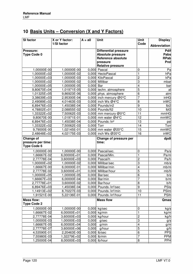
Reference Manual LMF
Page 120 LMF V7.0
10 Basis Units – Conversion (X and Y Factors)
SI factor X or Y factor: 1/SI factor
A = a0 Unit Unit Code
Display
Abbreviation
Pressure: Type Code 0
Differential pressure Absolute pressure Reference absolute pressure Relative pressure
PdifPabsRPab
Prel
1,00000E-00 1,00000E-00 0,000 Pascal 0 Pa1,00000E+02 1,00000E-02 0,000 HectoPascal 1 hPa1,00000E+03 1,00000E-03 0,000 KiloPascal 2 kPa1,00000E+02 1,00000E-02 0,000 Millibar 3 mbar1,00000E+05 1,00000E-05 0,000 Bar 4 bar9,80670E+04 1,01971E-05 0,000 techn. atmosphere 5 at1,01325E+05 9,86923E-06 0,000 phys. atmosphere 6 atm3,38639E+03 2,95300E-04 0,000 inch mercury @0°C 7 inHG2,49089E+02 4,01463E-03 0,000 inch Ws @4°C 8 inWC6,89476E+03 1,45038E-04 0,000 Pounds/in2 9 lbi24,78802E+01 2,08855E-02 0,000 Pounds/ft2 10 lbf21,33322E+02 7,50062E-03 0,000 mm mercury @0°C 11 mmHG9,80670E-00 1,01971E-01 0,000 mm water @4°C 12 mmWC6,89476E+03 1,45038E-04 0,000 Pounds /in² 13 psi1,33322E+02 7,50062E-03 0,000 Torr 14 Torr9,79000E-00 1,02145E-01 0,000 mm water @20°C 15 mmWC2,48648E+02 4,02175E-03 0,000 inch Ws @20°C 16 inWC
Change of pressure per time: Type Code 6
Change of pressure per time:
dpdt
1,00000E-00 1,00000E-00 0,000 Pascal/sec. 0 Pa/s1,66667E-02 6,00000E+01 0,000 Pascal/Min. 1 Pa/m2,77778E-04 3,60000E+03 0,000 Pascal/h 2 Pa/h1,00000E+02 1,00000E-02 0,000 Millibar/sec 3 mb/s1,66667E-00 6,00000E-01 0,000 Millibar/min 4 mb/m2,77778E-02 3,60000E+01 0,000 Millibar/hour 5 mb/h1,00000E+05 1,00000E-05 0,000 Bar/sec 6 b/s1,66667E+03 6,00000E-04 0,000 Bar/min 7 b/m2,77778E+01 3,60000E-02 0,000 Bar/hour 8 b/h6,89476E+03 1,45038E-04 0,000 Pounds /in²/sec 9 PSIs1,14913E+02 8,70227E-03 0,000 Pounds /in²/min 10 PSIm1,91521E-00 5,22136E-01 0,000 Pounds /in²/hour 11 PSIh
Mass flow: Type Code 2
Mass flow Qmas
1,00000E-00 1,00000E-00 0,000 kg/sec 0 kg/s1,66667E-02 6,00000E+01 0,000 kg/min 1 kg/m2,77778E-04 3,60000E+03 0,000 kg/hour 2 kg/h1,00000E-03 1,00000E+03 0,000 g/sec 3 g/s1,66667E-05 6,00000E+04 0,000 g/min 4 g/m2,77778E-07 3,60000E+06 0,000 g/hour 5 g/h4,53590E-01 2,20463E-00 0,000 lb/sec 6 PPS7,55980E-03 1,32279E+02 0,000 lb/min 7 PPM1,25000E-04 8,00000E+03 0,000 lb/hour 8 PPH
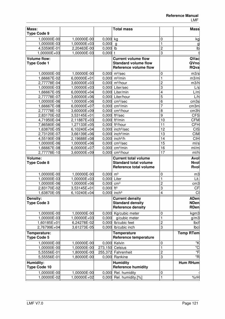
Reference Manual LMF
LMF V7.0 Page 121
Mass: Type Code 9
Total mass Mass
1,00000E-00 1,00000E-00 0,000 kg 0 kg1,00000E-03 1,00000E+03 0,000 g 1 g4,53590E-01 2,20463E-00 0,000 lb 2 lb1,00000E+03 1,00000E-03 0,000 t 3 t
Volume flow: Type Code 1
Current volume flow Standard volume flow Reference volume flow
QVacQVnoRQva
1,00000E-00 1,00000E-00 0,000 m³/sec 0 m3/s1,66667E-02 6,00000E+01 0,000 m³/min 1 m3/m2,77778E-04 3,60000E+03 0,000 m³/hour 2 m3/h1,00000E-03 1,00000E+03 0,000 Liter/sec 3 L/s1,66667E-05 6,00000E+04 0,000 Liter/min 4 L/m2,77778E-07 3,60000E+06 0,000 Liter/hour 5 L/h1,00000E-06 1,00000E+06 0,000 cm³/sec 6 cm3s1,66667E-08 6,00000E+07 0,000 cm³/min 7 cm3m2,77778E-10 3,60000E+09 0,000 cm³/hour 8 cm3h2,83170E-02 3,53145E+01 0,000 ft³/sec 9 CFS4,71950E-04 2,11887E+03 0,000 ft³/min 10 CFM7,86580E-06 1,27133E+05 0,000 ft³/hour 11 CFH1,63870E-05 6,10240E+04 0,000 inch³/sec 12 CIS2,73120E-07 3,66139E+06 0,000 inch³/min 13 CIM4,55190E-09 2,19688E+08 0,000 inch³/h 14 CIH1,00000E-06 1,00000E+06 0,000 cm³/sec 15 ml/s1,66667E-08 6,00000E+07 0,000 cm³/min 16 ml/m2,77778E-10 3,60000E+09 0,000 cm³/hour 17 ml/h
Volume: Type Code 8
Current total volume Standard total volume Reference total volume
AvolNvolRvol
1,00000E-00 1,00000E-00 0,000 m³ 0 m31,00000E-03 1,00000E+03 0,000 Liter 1 Lit.1,00000E-06 1,00000E+06 0,000 cm³ 2 cm32,83170E-02 3,53145E+01 0,000 ft³ 3 CF1,63870E-05 6,10240E+04 0,000 inch³ 4 CI
Density: Type Code 3
Current density Standard density Reference density
ADenNDenRDen
1,00000E-00 1,00000E-00 0,000 Kg/cubic meter 0 kgm31,00000E-03 1,00000E+03 0,000 g/cubic meter 1 g/m31,60185E+01 6,24278E-02 0,000 lb/cubic feet 2 lbcf2,76799E+04 3,61273E-05 0,000 lb/cubic inch 3 lbci
Temperature: Type Code 5
Temperature Reference temperature
Temp RTem
1,00000E-00 1,00000E-00 0,000 Kelvin 0 "K1,00000E-00 1,00000E-00 273,150 Celsius 1 "C5,55556E-01 1,80000E-00 255,372 Fahrenheit 2 "F5,55556E-01 1,80000E-00 0,000 Rankine 3 "R
Humidity: Type Code 10
Humidity Reference humidity
Hum RHum
1,00000E-00 1,00000E-00 0,000 Rel. humidity 0 -1,00000E-02 1,00000E+02 0,000 Rel. humidity.[%] 1 %rH
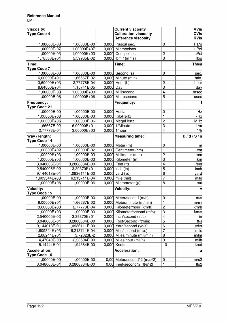
Reference Manual LMF
Page 122 LMF V7.0
Viscosity: Type Code 4
Current viscosity Calibration viscosity Reference viscosity
AVisCVisRVis
1,00000E-00 1,00000E-00 0,000 Pascal sec. 0 Pa*s1,00000E-07 1,00000E+07 0,000 Micropoises 1 uPoi1,00000E-03 1,00000E+03 0,000 Centipoises 2 cPoi1,78583E+01 5,59965E-02 0,000 lbm / (in * s) 3 lbis
Time: Type Code 7
Time: TMea
1,00000E-00 1,00000E-00 0,000 Second (s) 0 sec.6,00000E+01 1,66667E-02 0,000 Minute (min) 1 min.3,60000E+03 2,77778E-04 0,000 Hour (h) 2 hour8,64000E+04 1,15741E-05 0,000 Day 3 day1,00000E-03 1,00000E+03 0,000 Millisecond 4 msec1,00000E-06 1,00000E+06 0,000 Microsecond 5 usec
Frequency: Type Code 21
Frequency: f
1,00000E-00 1,00000E-00 0,000 Hertz 0 Hz1,00000E+03 1,00000E-03 0,000 KiloHertz 1 kHz1,00000E+06 1,00000E-06 0,000 MegaHertz 2 MHz1,66667E-02 6,00000E+01 0,000 1/Minute 3 1/m2,77778E-04 3,60000E+03 0,000 1/hour 4 1/h
Way / length: Type Code 14
Measuring time: D / d / S / s
1,00000E-00 1,00000E-00 0,000 Meter (m) 0 m1,00000E+02 1,00000E-02 0,000 Centimeter (cm) 1 cm1,00000E+03 1,00000E-03 0,000 Millimeter (mm) 2 mm1,00000E+03 1,00000E-03 0,000 Kilometer (m) 3 km
3,048006E-01 3,2808334E-00 0,000 Feet (ft) 4 feet2,540005E-02 3,39370E+01 0,000 inch (in) 5 inch9,144018E-01 1,0936111E-00 0,000 yard (yd) 6 yard1,609344E+03 6,213711E-04 0,000 mile (mil) 7 mile
1,00000E+06 1,00000E-06 0,000 Micrometer (µ) 8 mu
Velocity: Type Code 15
Velocity: v
1,00000E-00 1,00000E-00 0,000 Meter/second (m/s) 0 m/s6,00000E+01 1,66667E-02 0,000 Meter/minute (m/min) 1 m/mi3,60000E+03 2,77778E-04 0,000 Kilometer/hour (km/h) 2 km/h1,00000E+03 1,00000E-03 0,000 Kilometer/second (m/s) 3 km/s
2,540005E-02 3,39370E+01 0,000 Inch/second (in/s) 4 in3,048006E-01 3,2808334E-00 0,000 Foot/Second (ft/min) 5 ft/s9,144018E-01 1,0936111E-00 0,000 Yard/second (yd/s) 6 yd/s1,609344E+03 6,213711E-04 0,000 Mile/second (mil/s) 7 mils
2,68244E+01 3,72823E-2 0,000 Miles/minute (mil/min) 8 milm4,47040E-00 2,23694E-00 0,000 Miles/hour (mil/h) 9 milh5.14444E-01 1,94384E-00 0,000 Knots 10 knot
Acceleration: Type Code 16
Acceleration: a
1,00000E-00 1,00000E-00 0,00 Meter/second^2 (m/s^2) 0 m/s23,048006E-01 3,2808334E-00 0,00 Feet/second^2 (ft/s^2) 1 fts2
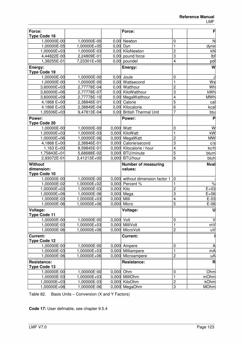
Reference Manual LMF
LMF V7.0 Page 123
Force: Type Code 18
Force: F
1,00000E-00 1,00000E-00 0,00 Newton 0 N1,00000E-05 1,00000E+05 0,00 Dyn 1 dyne1,00000E+03 1,00000E-03 0,00 KiloNewton 2 kN4,44822E-00 2,24809E-01 0,00 pound force 3 lbf1,38255E-01 7,23301E+00 0,00 poundel 4 pdl
Energy: Type Code 19
Energy: W
1,00000E-00 1,00000E-00 0,00 Joule 0 J1,00000E-00 1,00000E-00 0,00 Wattsecond 1 Ws3,60000E+03 2,77778E-04 0,00 Watthour 2 Wh3,60000E+06 2,77778E-07 0,00 KiloWatthour 3 kWh3,60000E+09 2,77778E-10 0,00 MegaWatthour 4 MWh4,1868 E+00 2,38846E-01 0,00 Calorie 5 cal4.1868 E+03 2,38849E-04 0,00 Kilocalorie 6 kcal1,05506E+03 9,47813E-04 0,00 British Thermal Unit 7 btu
Power: Type Code 20
Power: P
1,00000E-00 1,00000E-00 0,000 Watt 0 W1,00000E+03 1,00000E-03 0,000 KiloWatt 1 kW1,00000E+06 1,00000E-06 0,000 MegaWatt 2 MW4,1868 E+00 2,38846E-01 0,000 Calorie/second 3 c/s1,163 E+00 8,59845E-01 0,000 Kilocalorie / hour 4 kc/h
1,75843E+01 5,68688E-02 0,000 BTU/minute 5 btum2,93072E-01 3,41213E+00 0,000 BTU/hour 6 btuh
Without dimension: Type Code 10
Number of measuring values:
Nval
1,00000E-00 1,00000E-00 0,000 without dimension factor 1 0 -1,00000E-02 1,00000E+02 0,000 Percent % 1 %1,00000E+03 1,00000E-03 0,000 Kilo 2 E+031,00000E+06 1,00000E-06 0,000 Mega 3 E+061,00000E-03 1,00000E+03 0,000 Milli 4 E-031,00000E-06 1,00000E+06 0,000 Micro 5 E-06
Voltage: Type Code 11
Voltage: U
1,00000E-00 1,00000E-00 0,000 Volt 0 V1,00000E-03 1,00000E+03 0,000 MilliVolt 1 mV1,00000E-06 1,00000E+06 0,000 MicroVolt 2 uV
Current: Type Code 12
Current: I
1,00000E-00 1,00000E-00 0,000 Ampere 0 A1,00000E-03 1,00000E+03 0,000 Milliampere 1 mA1,00000E-06 1,00000E+06 0,000 Microampere 2 uA
Resistance: Type Code 13
Resistance: R
1,00000E-00 1,00000E-00 0,000 Ohm 0 Ohm1,00000E-03 1,00000E+03 0,000 MilliOhm 1 mOhm1,00000E+03 1,00000E-03 0,000 KiloOhm 2 kOhm1,00000E+06 1,00000E-06 0,000 MegaOhm 3 MOhm
Table 82. Basis Units – Conversion (X and Y Factors)
Code 17: User definable, see chapter 9.5.4
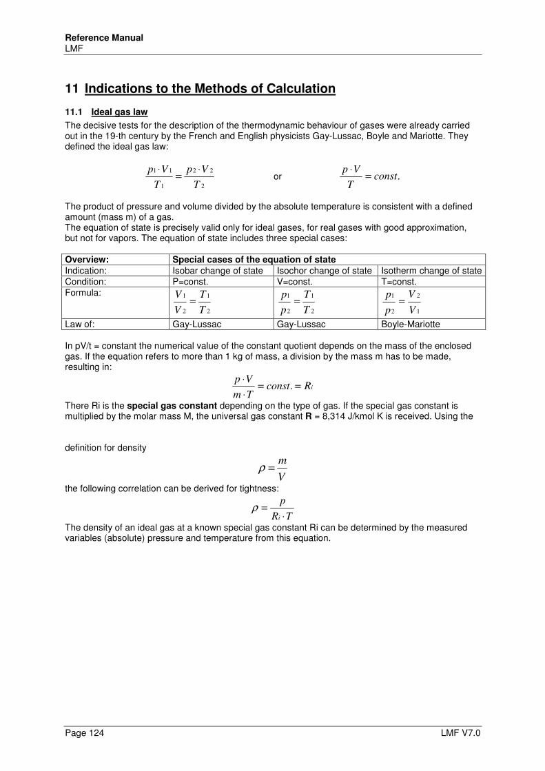
Reference Manual LMF
Page 124 LMF V7.0
11 Indications to the Methods of Calculation
11.1 Ideal gas law
The decisive tests for the description of the thermodynamic behaviour of gases were already carried out in the 19-th century by the French and English physicists Gay-Lussac, Boyle and Mariotte. They defined the ideal gas law:
2
22
1
11
T
Vp
T
Vp ⋅=
⋅ or .const
T
Vp=
⋅
The product of pressure and volume divided by the absolute temperature is consistent with a defined amount (mass m) of a gas. The equation of state is precisely valid only for ideal gases, for real gases with good approximation, but not for vapors. The equation of state includes three special cases: Overview: Special cases of the equation of state
Indication: Isobar change of state Isochor change of state Isotherm change of state Condition: P=const. V=const. T=const. Formula:
2
1
2
1
T
T
V
V=
2
1
2
1
T
T
p
p=
1
2
2
1
V
V
p
p=
Law of: Gay-Lussac Gay-Lussac Boyle-Mariotte In pV/t = constant the numerical value of the constant quotient depends on the mass of the enclosed gas. If the equation refers to more than 1 kg of mass, a division by the mass m has to be made, resulting in:
iRconstTm
Vp==
⋅
⋅.
There Ri is the special gas constant depending on the type of gas. If the special gas constant is multiplied by the molar mass M, the universal gas constant R = 8,314 J/kmol K is received. Using the
definition for density
V
m=ρ
the following correlation can be derived for tightness:
TR
p
i ⋅=ρ
The density of an ideal gas at a known special gas constant Ri can be determined by the measured variables (absolute) pressure and temperature from this equation.
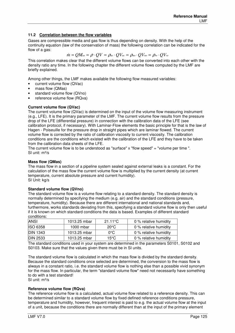
Reference Manual LMF
LMF V7.0 Page 125
11.2 Correlation between the flow variables
Gases are compressible media and gas flow is thus depending on density. With the help of the continuity equation (law of the conservation of mass) the following correlation can be indicated for the flow of a gas:
rerenonoacacas QVQVQVQVQMm ⋅=⋅=⋅=⋅== ρρρρ&
This correlation makes clear that the different volume flows can be converted into each other with the density ratio any time. In the following chapter the different volume flows computed by the LMF are briefly explained. Among other things, the LMF makes available the following flow measured variables: • current volume flow (QVac) • mass flow (QMas) • standard volume flow (QVno) • reference volume flow (RQva) Current volume flow (QVac) The current volume flow (QVac) is determined on the input of the volume flow measuring instrument (e.g., LFE). It is the primary parameter of the LMF. The current volume flow results from the pressure drop of the LFE (differential pressure) in connection with the calibration data of the LFE (see calibration protocol, if necessary). With Laminar-Flow elements the basic principle for that is the law of Hagen - Poiseuille for the pressure drop in straight pipes which are laminar flowed. The current volume flow is corrected by the ratio of calibration viscosity to current viscosity. The calibration conditions are the conditions which existed with the calibration of the LFE and they have to be taken from the calibration data sheets of the LFE. The current volume flow is to be understood as "surface" x "flow speed" = "volume per time ". SI unit: m³/s Mass flow (QMas) The mass flow in a section of a pipeline system sealed against external leaks is a constant. For the calculation of the mass flow the current volume flow is multiplied by the current density (at current temperature, current absolute pressure and current humidity). SI Unit: kg/s Standard volume flow (QVno) The standard volume flow is a volume flow relating to a standard density. The standard density is normally determined by specifying the medium (e.g. air) and the standard conditions (pressure, temperature, humidity). Because there are different international and national standards and, furthermore, works standards deviating from this, specifying a standard volume flow is only then useful if it is known on which standard conditions the data is based. Examples of different standard conditions:
ANSI 1013.25 mbar 21.11°C 0 % relative humidity
ISO 6358 1000 mbar 20°C 0 % relative humidity
DIN 1343 1013.25 mbar 0°C 0 % relative humidity
DIN 2533 1013.25 mbar 15°C 0 % relative humidity
The standard conditions used in your system are determined in the parameters S0101, S0102 and S0103. Make sure that the values given there must be in SI units. The standard volume flow is calculated in which the mass flow is divided by the standard density. Because the standard conditions once selected are determined, the conversion to the mass flow is always in a constant ratio, i.e. the standard volume flow is nothing else than a possible vivid synonym for the mass flow. In particular, the term "standard volume flow" need not necessarily have something to do with a test standard! SI unit: m³/s Reference volume flow (RQva) The reference volume flow is a calculated, actual volume flow related to a reference density. This can be determined similar to a standard volume flow by fixed defined reference conditions pressure, temperature and humidity, however, frequent interest is paid to e.g. the actual volume flow at the input of a unit, because the conditions there are normally different than at the input of the primary element

Reference Manual LMF
Page 126 LMF V7.0
for measuring the flow. If the conditions at the input of the unit are measured (= reference conditions) the LMF calculates the reference density and, thus, in the next step, the reference volume flow, by dividing the mass flow by the reference density. For details refer to Section 11.6.2. SI unit: m³/s
11.3 Adjustable types of gas
Settings Pn001, gas by primary element: operational kind of gas Air under atmospheric conditions is often the standard calibration media of primary elements for cost reasons. By use of the real density calculation for air in a range of 5..35°C, 800..1200 hPa absolute pressure and 0..95% of relative humidity, announced by a BIPM recommendation, the highest calculation accuracies are achieved. With precision applications the type of gas should possibly correspond with the operational type of gas when being calibrated. If another type of gas is applied, it must be made sure that the Reynolds number of the flow to be measured is similar to the Reynolds number of the calibration. Then with LFE there is the option to operate with another operational type of gas as well. As a default the following types of gas are deposited in the LMF: 1 - Air 2 - Argon 3 - Carbon dioxide 4 - Carbon monoxide 5 - Helium 6 - Hydrogen 7 - Nitrogen 8 - Oxygen 9 - Methane 10 - Propane 11 - n-butane 12 - Natural gas H 13 - Natural gas L 14 - Laughing gas 15 - Water vapor 16 - Xenon 17 - Nitrogen monoxide 18 - Neon 19 - Krypton 20 - Propene 21 - Ethane 22 - Ethene 23 - Ammonia 24 - Sulfur dioxide For other gases please ask TetraTec Instruments
11.4 Density calculation
The density is determined by the measured variables for temperature, absolute pressure and, if necessary, humidity. The following correlation can be used as a fist formula for the error estimation: 1° Temperature error, corresponds to 3 mbar pressure error, corresponds to 45% humidity error, corresponds to appr. 0.3% of error with density calculation! From this correlation the weighting of the sensors can be recognized, i.e., disregarding the humidity measurement causes the most minor error in the density calculation, for example. With the LMF the density can be calculated according to different models. These models are adjusted in parameter Pn003. In the following the different arithmetic models are explained.
Reference Manual LMF
LMF V7.0 Page 127
Ideal: [0] (Pn003=0) With the setting ideal no real gas corrections will be carried out. The calculation runs purely according to the ideal gas law without consideration of the current humidity. Real: [1] (Pn003=1) With the setting Real [1] real gas corrections are carried out for high pressures. The calculation runs taking into account the Real gas behaviour. By means of real gas factors and their development according to virial coefficients the pressure behaviour of real gases is described. This arithmetic model applies to all (dry) gases and should be always used with pressures >4 bar even with air. Real: [2] (Pn003=2) With the setting Real [2] real gas corrections are carried out taking into account humidity. The calculation is made according to BIPM and PTB recommendations. This arithmetic model only applies to air ≤ 4 bar taking into account humidity and it is the default setting for air.
11.5 Viscosity calculation
The viscosity is determined from the measured variables for temperature and, if necessary, humidity. The following correlation can be used as a fist formula for the error estimation: 1° Temperature error, corresponds to 45% humidity error, corresponds to appr. 0.2% of error with viscosity calculation! The viscosity is absolutely independent of pressure up to approx. 7 bar. With the LMF the viscosity can be computed according to different models. These models are adjusted in parameter Pn004. In the following the different arithmetic models are explained. Ideal: With the setting ideal a universal temperature correction of the viscosity of pure gases is carried out. Thus, only the behaviour of dry air is considered. The calculation with all types of gas runs according to the recommendations of Daubert & Danner. It applies for a wide range of temperature. Real: With the setting real the exact viscosity correction is carried out, in addition, by taking into account humidity, this is the default setting for air. The calculation proceeds according to the law of Kestin-Whitelaw and it applies only for air. Another arithmetic model for viscosity is planned for future times. This model should then, in addition, absolutely correct the pressure dependence of the viscosity with pressures ≥ 7 bar.
11.6 Allocation of Sensors and Measurands
The flow measurement requires specific input variables with predefined meanings, e.g. to calculate the density and viscosity. In addition, there are optional input variables whose meaning can be determined to a specific project. Allocation of the sensors is carried out at multiple levels: • Initially, the sensors can be fundamentally allocated arbitrarily to the hardware input available.
Normally, this allocation is determined at the start of the project by the project manager according to specific conventions. Subsequent change is no longer easily possible.
• Within the framework of commissioning, each sensor is allocated to a minimum of one linearization data set (S2nxx-Blocks, n = dataset number). Amongst other things, each linearization data set contains how the linearization procedure is determined, the compensation polynomial, an input and output scale, the serial number, monitoring limits and allocation to the hardware input. The sequence of the linearization data sets is generally arbitrary. More linearization data sets can also be allocated than is necessary for the flow measurement. For example, multiple linearization data sets can access the same hardware input (sensor), e.g. in order to be able to select between alternative linearization procedures.
Reference Manual LMF
Page 128 LMF V7.0
• In the same manner, a minimum of one linearization data set can be created for each primary element (S4nxx-Blocks). This contains, et al., data about the type of primary element, medium, calibration conditions, compensation polynomial, scaling factors and serial number. If multiple types of gas or test conditions are used, there are frequently multiple linearization data sets for the same primary element.
• The P-Parameters are specific to the program. There are 10 programs that equate to the parameter blocks P0xx to P9xx. There are specific parameter blocks for specific input variables in each program. Here, amongst other things, it is determined which sensor is used for the according input variable, by selecting the suitable linearization data set.
An overview of the parameter blocks and their meanings are given as follows: 1. Pn000-Block: Primary element
A primary element can be, e.g. an active pressure transmitter such as a LFE, an orifice or a Venturi tube. However, it can also be a counter, mass flow sensor etc.
2. Pn010-Block: Primary measurand If a primary element, e.g. a LFE, an orifice or a Venturi tube be used for the flow measurement, the primary measurand is the active pressure, i.e. the differential pressure between the input and output and constriction.
3. Pn020, Pn030 and Pn040-Blocks: Sensors for the measurement conditions To calculate the flow, the measurement conditions of static absolute pressure, temperature and relative humidity are required. Using these, the variables density and viscosity at the input of the primary element are calculated. In turn, these are required in order to calculate the volume flows and, insofar as the primary element is not a mass flow sensor, also the mass flow. Also refer to Sections 11.6.1.1, 11.6.1.3 and 11.6.1.4.
4. Pn050, Pn60 and Pn070-Blocks: Sensors for reference conditions Reference conditions at an arbitrary measuring point in the flow system, e.g. at the input of the unit (test conditions). Using the reference conditions, it is possible to calculate, e.g. the density at the location of the reference measuring point and, thus, if the mass flow is known, the local volume flow. In addition, the reference conditions can be used for correction calculations with the objective to compensate for external influences and, thus, to define a measured variable that only correlates with the existing characteristics of the unit. Also refer to Sections 11.6.2.1, 11.6.2.2 and 11.6.2.3.
5. Pn075, Pn080, Pn085, Pn090 and Pn095-Blocks: Auxiliary inputs The auxiliary inputs (Aux0 to Aux 4) can be arbitrarily defined, e.g. for additional relative or differential pressure sensors or a mass flow sensor. Also refer to Section 11.6.3. Special handling of mass flow sensor: In order to also interpret the signal of a mass flow sensor regarding the complete flow measurement as mass flow, the mass flow sensor must be established as a sensor, auxiliary input and as primary element: - Initially, it is created as a sensor in a S2nxx dataset, e.g. in the S27xx-Block - An auxiliary input accesses the linearization data set of this sensor, e.g. auxiliary input 0
(Pn075-Block). Then Pn075=7 is set. - Subsequently, the mass flow sensor is created in a S4nxx dataset as a primary element, e.g.
in the S43xx-Block. Then S4300=100 is set (type direct mass flow input) and S4330=0 is set (auxiliary input 0)
6. S9010-Block: Basic system pressure The basic system pressure is the central absolute pressure that is used to be able to convert the relative pressure to absolute pressures. The relative pressures are frequently correlated to the ambient pressure. In this case, the basic system pressure is synonymous with the barometric ambient pressure.
The following sections give an overview of the different settings of the sensors that can be connected to determine the density and viscosity at the LMF (independent of the primary element).
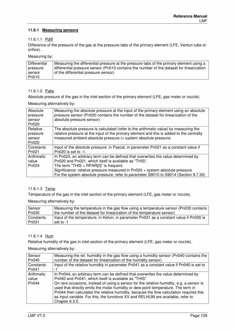
Reference Manual LMF
LMF V7.0 Page 129
11.6.1 Measuring sensors
11.6.1.1 Pdiff
Difference of the pressure of the gas at the pressure tabs of the primary element (LFE, Venturi tube or orifice).
Measuring by:
Differential pressure sensor Pn010
Measuring the differential pressure at the pressure tabs of the primary element using a differential pressure sensor (Pn010 contains the number of the dataset for linearization of the differential pressure sensor)
11.6.1.2 Pabs
Absolute pressure of the gas in the inlet section of the primary element (LFE, gas meter or nozzle).
Measuring alternatively by:
Absolute pressure sensor Pn020
Measuring the absolute pressure at the input of the primary element using an absolute pressure sensor (Pn020 contains the number of the dataset for linearization of the absolute pressure sensor)
Relative pressure sensor Pn020
The absolute pressure is calculated (refer to the arithmetic value) by measuring the relative pressure at the input of the primary element and this is added to the centrally measured ambient absolute pressure (= system absolute pressure.
Constants Pn021
Input of the absolute pressure, in Pascal, in parameter Pn021 as a constant value if Pn020 is set to -1.
Arithmetic value Pn024
In Pn024, an arbitrary term can be defined that overwrites the value determined by Pn020 and Pn021, which itself is available as "THIS“. The term "THIS + RPAR[0]“ is frequent. Significance: relative pressure measured in Pn020 + system absolute pressure For the system absolute pressure, refer to parameter S9010 to S9014 (Section 9.7.30)
11.6.1.3 Temp
Temperature of the gas in the inlet section of the primary element (LFE, gas meter or nozzle).
Measuring alternatively by:
Sensor Pn030
Measuring the temperature in the gas flow using a temperature sensor (Pn030 contains the number of the dataset for linearization of the temperature sensor)
Constants Pn031
Input of the temperature, in Kelvin, in parameter Pn031 as a constant value if Pn030 is set to -1
11.6.1.4 Hum
Relative humidity of the gas in inlet section of the primary element (LFE, gas meter or nozzle).
Measuring alternatively by:
Sensor Pn040
Measuring the rel. humidity in the gas flow using a humidity sensor (Pn040 contains the number of the dataset for linearization of the humidity sensor)
Constants Pn041
Input of the relative humidity in parameter Pn041 as a constant value if Pn040 is set to -1
Arithmetic value Pn044
In Pn044, an arbitrary term can be defined that overwrites the value determined by Pn040 and Pn041, which itself is available as "THIS“. On rare occasions, instead of using a sensor for the relative humidity, e.g. a sensor is used that directly emits the molar humidity or dew point temperature. The term in Pn044 then calculates the relative humidity, because the flow calculation requires this as input variable. For this, the functions XV and RELHUM are available, refer to Chapter 6.3.5.
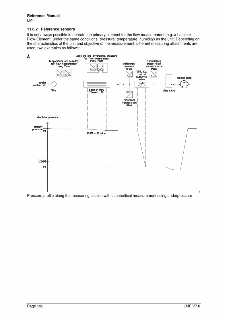
Reference Manual LMF
Page 130 LMF V7.0
11.6.2 Reference sensors
It is not always possible to operate the primary element for the flow measurement (e.g. a Laminar-Flow-Element) under the same conditions (pressure, temperature, humidity) as the unit. Depending on the characteristics of the unit and objective of the measurement, different measuring attachments are used, two examples as follows:
Pressure profile along the measuring section with supercritical measurement using underpressure
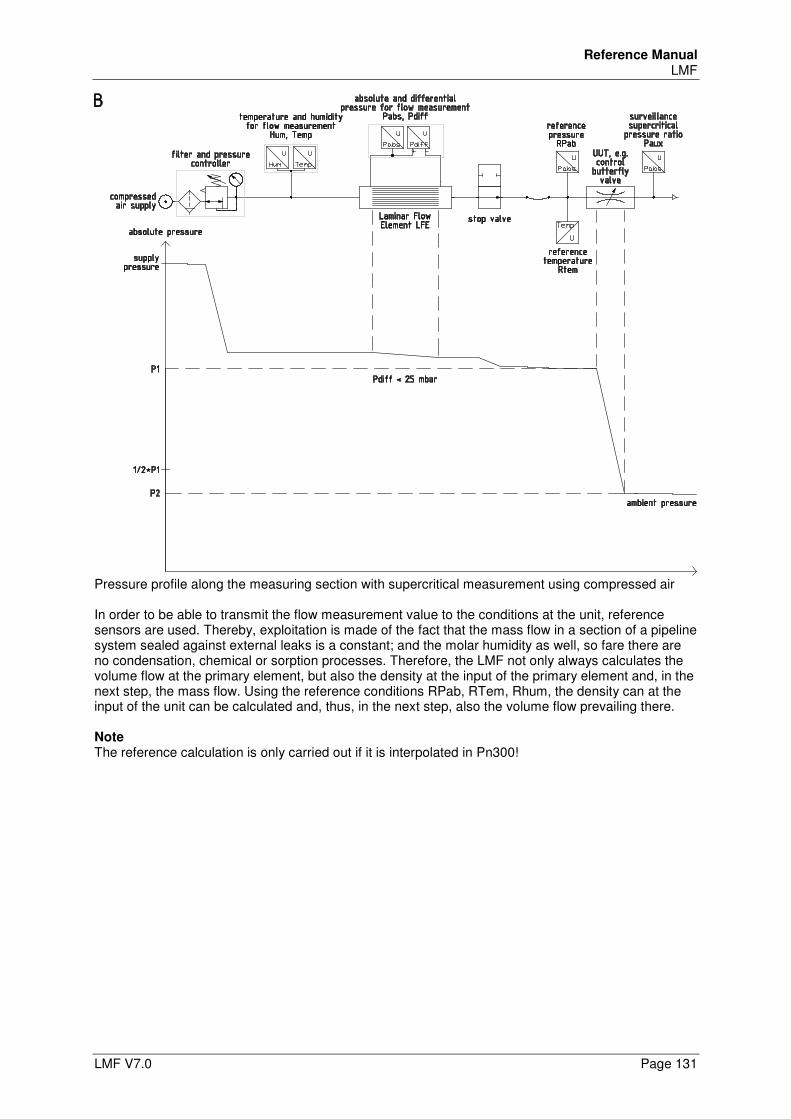
Reference Manual LMF
LMF V7.0 Page 131
Pressure profile along the measuring section with supercritical measurement using compressed air In order to be able to transmit the flow measurement value to the conditions at the unit, reference sensors are used. Thereby, exploitation is made of the fact that the mass flow in a section of a pipeline system sealed against external leaks is a constant; and the molar humidity as well, so fare there are no condensation, chemical or sorption processes. Therefore, the LMF not only always calculates the volume flow at the primary element, but also the density at the input of the primary element and, in the next step, the mass flow. Using the reference conditions RPab, RTem, Rhum, the density can at the input of the unit can be calculated and, thus, in the next step, also the volume flow prevailing there. Note The reference calculation is only carried out if it is interpolated in Pn300!
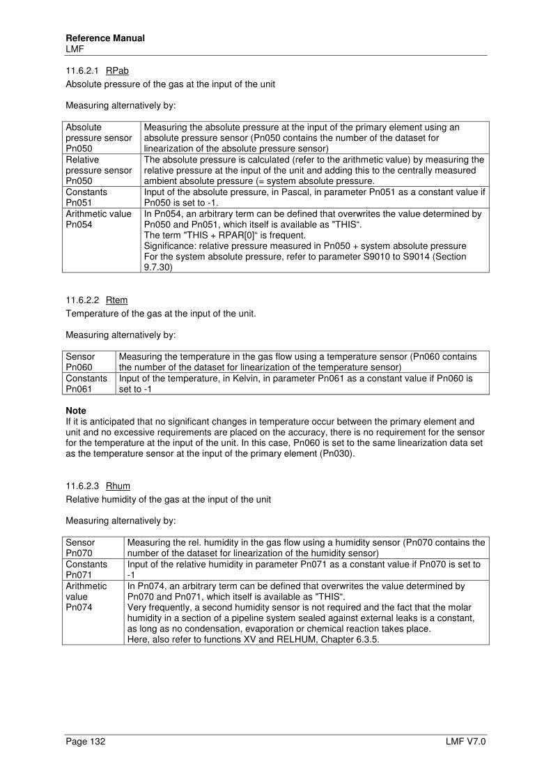
Reference Manual LMF
Page 132 LMF V7.0
11.6.2.1 RPab
Absolute pressure of the gas at the input of the unit Measuring alternatively by: Absolute pressure sensor Pn050
Measuring the absolute pressure at the input of the primary element using an absolute pressure sensor (Pn050 contains the number of the dataset for linearization of the absolute pressure sensor)
Relative pressure sensor Pn050
The absolute pressure is calculated (refer to the arithmetic value) by measuring the relative pressure at the input of the unit and adding this to the centrally measured ambient absolute pressure (= system absolute pressure.
Constants Pn051
Input of the absolute pressure, in Pascal, in parameter Pn051 as a constant value if Pn050 is set to -1.
Arithmetic value Pn054
In Pn054, an arbitrary term can be defined that overwrites the value determined by Pn050 and Pn051, which itself is available as "THIS“. The term "THIS + RPAR[0]“ is frequent. Significance: relative pressure measured in Pn050 + system absolute pressure For the system absolute pressure, refer to parameter S9010 to S9014 (Section 9.7.30)
11.6.2.2 Rtem
Temperature of the gas at the input of the unit. Measuring alternatively by: Sensor Pn060
Measuring the temperature in the gas flow using a temperature sensor (Pn060 contains the number of the dataset for linearization of the temperature sensor)
Constants Pn061
Input of the temperature, in Kelvin, in parameter Pn061 as a constant value if Pn060 is set to -1
Note If it is anticipated that no significant changes in temperature occur between the primary element and unit and no excessive requirements are placed on the accuracy, there is no requirement for the sensor for the temperature at the input of the unit. In this case, Pn060 is set to the same linearization data set as the temperature sensor at the input of the primary element (Pn030).
11.6.2.3 Rhum
Relative humidity of the gas at the input of the unit Measuring alternatively by: Sensor Pn070
Measuring the rel. humidity in the gas flow using a humidity sensor (Pn070 contains the number of the dataset for linearization of the humidity sensor)
Constants Pn071
Input of the relative humidity in parameter Pn071 as a constant value if Pn070 is set to -1
Arithmetic value Pn074
In Pn074, an arbitrary term can be defined that overwrites the value determined by Pn070 and Pn071, which itself is available as "THIS“. Very frequently, a second humidity sensor is not required and the fact that the molar humidity in a section of a pipeline system sealed against external leaks is a constant, as long as no condensation, evaporation or chemical reaction takes place. Here, also refer to functions XV and RELHUM, Chapter 6.3.5.
Reference Manual LMF
LMF V7.0 Page 133
11.6.3 Auxiliary
Up to five auxiliary inputs are available. The term "auxiliary input“ is possibly somewhat confusing. It does not necessarily indicate additional electrical inputs, but is primarily an extension of the LMF software, with which further sensor values can be integrated without predefined application. That can be other sensors, it can also be the same sensors again integrated that are already integrated for the predefined applications. Frequent applications: • If the actual measurement value is overwritten by a term (e.g. in Pn024), the actual measurement
value is also required (e.g. in order to present it on the display), an auxiliary input is readily used that accesses the same linearization data set, however, without a correction term. Frequently used for relative pressure sensors utilized for determining the absolute measuring pressure, using a correction term in Pn024.
• If multiple sensors are operated in parallel for the same measuring task (e.g. with different measuring ranges), it is desired that all sensor values are presented on the display and not only those currently used. In this case, these sensors are readily applied to an auxiliary input, parallel to the application for the flow calculation.
• If other measurands should be recorded in addition to the flow and if it is only for the purpose of documentation, the associated sensors are applied to the auxiliary inputs. Examples: Sensors for travel, force, control signal at the unit etc.
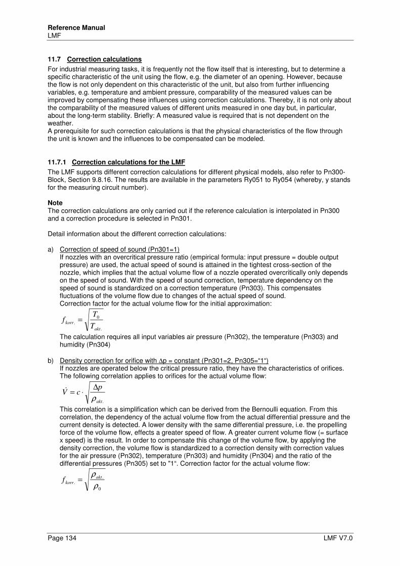
Reference Manual LMF
Page 134 LMF V7.0
11.7 Correction calculations
For industrial measuring tasks, it is frequently not the flow itself that is interesting, but to determine a specific characteristic of the unit using the flow, e.g. the diameter of an opening. However, because the flow is not only dependent on this characteristic of the unit, but also from further influencing variables, e.g. temperature and ambient pressure, comparability of the measured values can be improved by compensating these influences using correction calculations. Thereby, it is not only about the comparability of the measured values of different units measured in one day but, in particular, about the long-term stability. Briefly: A measured value is required that is not dependent on the weather. A prerequisite for such correction calculations is that the physical characteristics of the flow through the unit is known and the influences to be compensated can be modeled.
11.7.1 Correction calculations for the LMF
The LMF supports different correction calculations for different physical models, also refer to Pn300-Block, Section 9.8.16. The results are available in the parameters Ry051 to Ry054 (whereby, y stands for the measuring circuit number). Note The correction calculations are only carried out if the reference calculation is interpolated in Pn300 and a correction procedure is selected in Pn301. Detail information about the different correction calculations: a) Correction of speed of sound (Pn301=1)
If nozzles with an overcritical pressure ratio (empirical formula: input pressure = double output pressure) are used, the actual speed of sound is attained in the tightest cross-section of the nozzle, which implies that the actual volume flow of a nozzle operated overcritically only depends on the speed of sound. With the speed of sound correction, temperature dependency on the speed of sound is standardized on a correction temperature (Pn303). This compensates fluctuations of the volume flow due to changes of the actual speed of sound. Correction factor for the actual volume flow for the initial approximation:
.
0
.
akt
korrT
Tf =
The calculation requires all input variables air pressure (Pn302), the temperature (Pn303) and humidity (Pn304)
b) Density correction for orifice with ∆p = constant (Pn301=2, Pn305=“1“) If nozzles are operated below the critical pressure ratio, they have the characteristics of orifices. The following correlation applies to orifices for the actual volume flow:
.akt
pcV
ρ
∆⋅=&
This correlation is a simplification which can be derived from the Bernoulli equation. From this correlation, the dependency of the actual volume flow from the actual differential pressure and the current density is detected. A lower density with the same differential pressure, i.e. the propelling force of the volume flow, effects a greater speed of flow. A greater current volume flow (= surface x speed) is the result. In order to compensate this change of the volume flow, by applying the density correction, the volume flow is standardized to a correction density with correction values for the air pressure (Pn302), temperature (Pn303) and humidity (Pn304) and the ratio of the differential pressures (Pn305) set to "1“. Correction factor for the actual volume flow:
0
.
.ρ
ρakt
korrf =
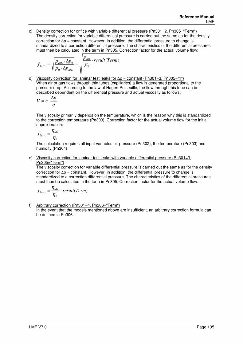
Reference Manual LMF
LMF V7.0 Page 135
c) Density correction for orifice with variable differential pressure (Pn301=2, Pn305=“Term“) The density correction for variable differential pressure is carried out the same as for the density correction for ∆p = constant. However, in addition, the differential pressure to change is standardized to a correction differential pressure. The characteristics of the differential pressures must then be calculated in the term in Pn305. Correction factor for the actual volume flow:
)(0
.0
0.
.
Termresult
p
pf
akt
akt
aktkorr
⋅=
∆⋅
∆⋅= ρ
ρ
ρ
ρ
d) Viscosity correction for laminar test leaks for ∆p = constant (Pn301=3, Pn305=“1“) When air or gas flows through thin tubes (capillaries) a flow is generated proportional to the pressure drop. According to the law of Hagen-Poiseuille, the flow through this tube can be described dependent on the differential pressure and actual viscosity as follows:
η
pcV
∆⋅=&
The viscosity primarily depends on the temperature, which is the reason why this is standardized to the correction temperature (Pn303). Correction factor for the actual volume flow for the initial approximation:
.0
.
.η
ηakt
korrf =
The calculation requires all input variables air pressure (Pn302), the temperature (Pn303) and humidity (Pn304)
e) Viscosity correction for laminar test leaks with variable differential pressure (Pn301=3, Pn305=“Term“) The viscosity correction for variable differential pressure is carried out the same as for the density correction for ∆p = constant. However, in addition, the differential pressure to change is standardized to a correction differential pressure. The characteristics of the differential pressures must then be calculated in the term in Pn305. Correction factor for the actual volume flow:
)(.0
.
. Termresultf akt
korr ⋅=η
η
f) Arbitrary correction (Pn301=4, Pn306=“Term“)
In the event that the models mentioned above are insufficient, an arbitrary correction formula can be defined in Pn306.
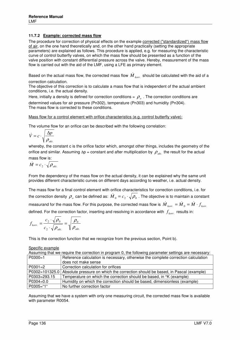
Reference Manual LMF
Page 136 LMF V7.0
11.7.2 Example: corrected mass flow
The procedure for correction of physical effects on the example corrected ("standardized“) mass flow of air, on the one hand theoretically and, on the other hand practically (setting the appropriate parameters) are explained as follows. This procedure is applied, e.g. for measuring the characteristic curve of control butterfly valves, on which the mass flow should be presented as a function of the valve position with constant differential pressure across the valve. Hereby, measurement of the mass flow is carried out with the aid of the LMF, using a LFE as primary element.
Based on the actual mass flow, the corrected mass flow .korrM& should be calculated with the aid of a
correction calculation. The objective of this correction is to calculate a mass flow that is independent of the actual ambient conditions, i.e. the actual density.
Here, initially a density is defined for correction conditions = oρ . The correction conditions are
determined values for air pressure (Pn302), temperature (Pn303) and humidity (Pn304). The mass flow is corrected to these conditions. Mass flow for a control element with orifice characteristics (e.g. control butterfly valve): The volume flow for an orifice can be described with the following correlation:
.akt
pcV
ρ
∆⋅=&
whereby, the constant c is the orifice factor which, amongst other things, includes the geometry of the
orifice and similar. Assuming ∆p = constant and after multiplication by .aktρ the result for the actual
mass flow is:
.2 aktcM ρ⋅=&
From the dependency of the mass flow on the actual density, it can be explained why the same unit provides different characteristic curves on different days according to weather, i.e. actual density. The mass flow for a final control element with orifice characteristics for correction conditions, i.e. for
the correction density oρ can be defined as: 020 ρ⋅= cM& . The objective is to maintain a constant
measurand for the mass flow. For this purpose, the corrected mass flow is .0. korrkorr fMMM ⋅== &&&
defined. For the correction factor, inserting and resolving in accordance with .korrf results in:
.
0
.2
02
.
aktakt
korrc
cf
ρ
ρ
ρ
ρ=
⋅
⋅=
This is the correction function that we recognize from the previous section, Point b). Specific example Assuming that we require the correction in program 0, the following parameter settings are necessary: P0300=1 Reference calculation is necessary, otherwise the complete correction calculation
does not make sense P0301=2 Correction calculation for orifices P0302=101325.0 Absolute pressure on which the correction should be based, in Pascal (example) P0303=293.15 Temperature on which the correction should be based, in °K (example) P0304=0.0 Humidity on which the correction should be based, dimensionless (example) P0305=“1“ No further correction factor Assuming that we have a system with only one measuring circuit, the corrected mass flow is available with parameter R0054.
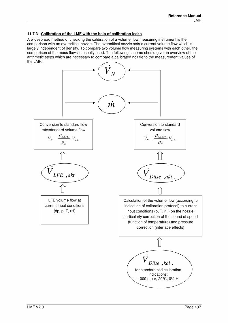
Reference Manual LMF
LMF V7.0 Page 137
11.7.3 Calibration of the LMF with the help of calibration leaks
A widespread method of checking the calibration of a volume flow measuring instrument is the comparison with an overcritical nozzle. The overcritical nozzle sets a current volume flow which is largely independent of density. To compare two volume flow measuring systems with each other, the comparison of the mass flows is usually used. The following scheme should give an overview of the arithmetic steps which are necessary to compare a calibrated nozzle to the measurement values of the LMF:
LFE volume flow at
current input conditions
(dp, p, T, rH)
.,aktLFEV&
NV&
m&
.,kalDüseV& for standardized calibration
indications: 1000 mbar, 20°C, 0%rH
Conversion to standard
volume flow
.
,
act
N
Düsea
N VV && ⋅=ρ
ρ
Calculation of the volume flow (according to
indication of calibration protocol) to current
input conditions (p, T, rH) on the nozzle,
particularly correction of the sound of speed
(function of temperature) and pressure
correction (interface effects)
Conversion to standard flow
rate/standard volume flow
.
,
act
N
LFEa
N VV && ⋅=ρ
ρ
.,aktDüseV&
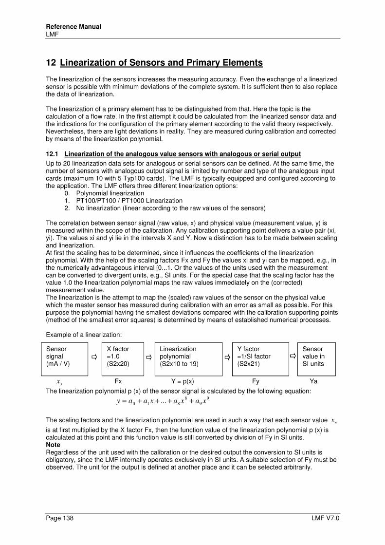
Reference Manual LMF
Page 138 LMF V7.0
12 Linearization of Sensors and Primary Elements
The linearization of the sensors increases the measuring accuracy. Even the exchange of a linearized sensor is possible with minimum deviations of the complete system. It is sufficient then to also replace the data of linearization. The linearization of a primary element has to be distinguished from that. Here the topic is the calculation of a flow rate. In the first attempt it could be calculated from the linearized sensor data and the indications for the configuration of the primary element according to the valid theory respectively. Nevertheless, there are light deviations in reality. They are measured during calibration and corrected by means of the linearization polynomial.
12.1 Linearization of the analogous value sensors with analogous or serial output
Up to 20 linearization data sets for analogous or serial sensors can be defined. At the same time, the number of sensors with analogous output signal is limited by number and type of the analogous input cards (maximum 10 with 5 Typ100 cards). The LMF is typically equipped and configured according to the application. The LMF offers three different linearization options:
0. Polynomial linearization 1. PT100/PT100 / PT1000 Linearization 2. No linearization (linear according to the raw values of the sensors)
The correlation between sensor signal (raw value, x) and physical value (measurement value, y) is measured within the scope of the calibration. Any calibration supporting point delivers a value pair (xi, yi). The values xi and yi lie in the intervals X and Y. Now a distinction has to be made between scaling and linearization. At first the scaling has to be determined, since it influences the coefficients of the linearization polynomial. With the help of the scaling factors Fx and Fy the values xi and yi can be mapped, e.g., in the numerically advantageous interval [0...1. Or the values of the units used with the measurement can be converted to divergent units, e.g., SI units. For the special case that the scaling factor has the value 1.0 the linearization polynomial maps the raw values immediately on the (corrected) measurement value. The linearization is the attempt to map the (scaled) raw values of the sensor on the physical value which the master sensor has measured during calibration with an error as small as possible. For this purpose the polynomial having the smallest deviations compared with the calibration supporting points (method of the smallest error squares) is determined by means of established numerical processes. Example of a linearization:
sx Fx Y = p(x) Fy Ya
The linearization polynomial p (x) of the sensor signal is calculated by the following equation:
9
9
8
810 ... xaxaxaay ++++=
The scaling factors and the linearization polynomial are used in such a way that each sensor value sx
is at first multiplied by the X factor Fx, then the function value of the linearization polynomial p (x) is calculated at this point and this function value is still converted by division of Fy in SI units. Note Regardless of the unit used with the calibration or the desired output the conversion to SI units is obligatory, since the LMF internally operates exclusively in SI units. A suitable selection of Fy must be observed. The unit for the output is defined at another place and it can be selected arbitrarily.
Sensor signal (mA / V)
Linearization polynomial (S2x10 to 19)
Y factor =1/SI factor (S2x21)
Sensor value in SI units
X factor =1.0 (S2x20)
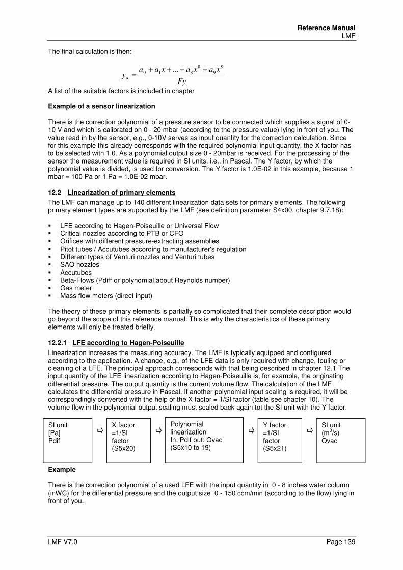
Reference Manual LMF
LMF V7.0 Page 139
The final calculation is then:
Fy
xaxaxaaya
9
9
8
810 ... ++++=
A list of the suitable factors is included in chapter Example of a sensor linearization There is the correction polynomial of a pressure sensor to be connected which supplies a signal of 0-10 V and which is calibrated on 0 - 20 mbar (according to the pressure value) lying in front of you. The value read in by the sensor, e.g., 0-10V serves as input quantity for the correction calculation. Since for this example this already corresponds with the required polynomial input quantity, the X factor has to be selected with 1.0. As a polynomial output size 0 - 20mbar is received. For the processing of the sensor the measurement value is required in SI units, i.e., in Pascal. The Y factor, by which the polynomial value is divided, is used for conversion. The Y factor is 1.0E-02 in this example, because 1 mbar = 100 Pa or 1 Pa = 1.0E-02 mbar.
12.2 Linearization of primary elements
The LMF can manage up to 140 different linearization data sets for primary elements. The following primary element types are supported by the LMF (see definition parameter S4x00, chapter 9.7.18): LFE according to Hagen-Poiseuille or Universal Flow Critical nozzles according to PTB or CFO Orifices with different pressure-extracting assemblies Pitot tubes / Accutubes according to manufacturer's regulation Different types of Venturi nozzles and Venturi tubes SAO nozzles Accutubes Beta-Flows (Pdiff or polynomial about Reynolds number) Gas meter Mass flow meters (direct input) The theory of these primary elements is partially so complicated that their complete description would go beyond the scope of this reference manual. This is why the characteristics of these primary elements will only be treated briefly.
12.2.1 LFE according to Hagen-Poiseuille
Linearization increases the measuring accuracy. The LMF is typically equipped and configured according to the application. A change, e.g., of the LFE data is only required with change, fouling or cleaning of a LFE. The principal approach corresponds with that being described in chapter 12.1 The input quantity of the LFE linearization according to Hagen-Poiseuille is, for example, the originating differential pressure. The output quantity is the current volume flow. The calculation of the LMF calculates the differential pressure in Pascal. If another polynomial input scaling is required, it will be correspondingly converted with the help of the X factor = 1/SI factor (table see chapter 10). The volume flow in the polynomial output scaling must scaled back again tot the SI unit with the Y factor. Example
There is the correction polynomial of a used LFE with the input quantity in 0 - 8 inches water column (inWC) for the differential pressure and the output size 0 - 150 ccm/min (according to the flow) lying in front of you.
SI unit [Pa] Pdif
X factor =1/SI factor (S5x20)
Polynomial linearization In: Pdif out: Qvac (S5x10 to 19)
Y factor =1/SI factor (S5x21)
SI unit (m
3/s)
Qvac
Reference Manual LMF
Page 140 LMF V7.0
The internal calculation calculates the measured differential pressure with the SI unit Pa. With the help of the X factor the pressure in Pa will be scaled on the necessary polynomial input quantity. In this example the X factor is (S5x020 =) 4,01463E-03. As a polynomial output size 0 - 150 cfm/min is received (cubic feet per minute). For further processing the result is required in SI unit, i.e., in m3 / sec. The Y factor serves for conversion. In this example the Y factor is (S5x021 =) 2,11887E+03 for the conversion from cfm/min to m3/sec.
12.2.2 LFE according to Universal Flow
If laminar flow elements are used with higher pressures, the atmospheric calibration according to Hagen-Poiseuille fails, since, e.g., density, viscosity and pressure are no independent variables. With these applications the Universal Flow calibration is used. This is a process in which the calibration supporting points are converted to independent variables at first.
12.2.3 Overcritical nozzles according to DIN EN ISO 9300
Overcritical nozzles supply a current volume flow which is widely independent of input pressure and output pressure. But it is necessary there that the overcritical nozzles are operated with a pressure ratio pe/pa ≥ 2. Basic principle for this effect is that with a overcritically operated nozzle the flow reaches speed of sound in the smallest cross section. The speed of sound depends (indirectly) on temperature. To compensate the temperature dependence with the evaluation of the overcritical nozzle, a temperature measurement is necessary in addition to pressure measurement therefore.
12.2.4 Gas meter
When calibrating data for gas meters irregularities of the gas meter are compensated with the help of the linearization polynomial. These irregularities are based, e.g., on leakage, friction, resonances and machining tolerances.
12.2.5 Orifices, Venturi tubes, Pitot tubes / Accutubes...
With these so-called “square root devices” a pressure drop arises, which is proportionally to the square of the volume flow or, in other words, the volume flow is proportional to the square root of the measured pressure drop:
pV ∆~&
“Square root devices”, as a rule, can only be used in the measuring range 1:6, since the differential pressure must be measured otherwise with a too high (any more payable) accuracy. Another important size in the operation of these primary elements is the Reynolds number. The Reynolds number characterizes the flow and it is taken into consideration with the calculation of the volume flow
Reference Manual LMF
LMF V7.0 Page 141
13 Allocation of the Sensors and Primary Elements
The allocation of the sensors and the primary elements to the measuring sections and programs shall be explained with an example. Example A double section measuring instrument is equipped with 7 sensors and 2 LFE. Sensor 0: Differential pressure (active pressure), section 0; Parameter set: S2000 - S2031 for linearization Sensor 1: Absolute pressure, section 0; Parameter set: S2100 - S2131 for linearization Sensor 2: Gas temperature, section 0; Parameter set: S2200 - S2231 for linearization Sensor 3: Humidity, section 0; Parameter set: S2300 - S3231 for linearization Sensor 4: Differential pressure (active pressure), section 1; Parameter set: S2400 - S2431 for linearization Sensor 5: Absolute pressure, section 1; Parameter set: S2500 - S2531 for linearization Sensor 6: Gas temperature, section 1; Parameter set: S2600 - S2631 for linearization LFE 0: LFE, section 0; Parameter set: S4000 – S4022 for linearization LFE 1: LFE, section 1; Parameter set: S4100 – S4122 for linearization At first a program is allocated to the measuring circuits (section 0 or section 1): S1000 = 0 S1001 = 4 Section 0 is evaluated therefore with measuring program 0, section 1 is evaluated with measuring program 4. Each measuring program now needs the different input quantities for the flow calculation. Program 0: P0000 = 0; in program 0 the primary element defined in parameter set P4000 to P4022 is evaluated P0010 = 0; in program 0 sensor 0 is used for the differential pressure measurement P0020 = 1; in program 0 sensor 1 is used for the absolute pressure measurement P0030 = 2; in program 0 sensor 2 is used for the temperature measurement P0040 = 3; in program 0 sensor 3 is used for the humidity measurement P0050 = -1; in program 0 the fixed value from P0051 is used for the absolute reference pressure P0060 = -1; in program 0 the fixed value from P0061 is used for the reference temperature P0070 = -1; in program 0 the fixed value from P0071 is used for the reference humidity

Reference Manual LMF
Page 142 LMF V7.0
Program 4: P4000 = 1; in program 4 the primary element defined in parameter set P4100 to P4122 is evaluated P4010 = 4; in program 4 sensor 4 is used for the differential pressure measurement P4020 = 5; in program 4 sensor 5 is used for the absolute pressure measurement P4030 = 6; in program 4 sensor 6 is used for the temperature measurement P4040 = -1; in program 4 the fixed value from P4041 is used for humidity P4050 = -1; in program 4 the fixed value from P4051 is used for the absolute reference pressure P4060 = -1; in program 4 the fixed value from P4061 is used for the reference temperature P4070 = -1; in program 4 the fixed value from P4071 is used for the reference humidity Thus the basic configuration is specified for each of both measuring programs and the desired sensors are taken into consideration for the measurement. Now the fine tuning in the next steps remains: Units, comma place, measured variables etc. must be configured for the display.
Reference Manual LMF
LMF V7.0 Page 143
14 Measuring and Correction Processes
A widespread measuring method for the measurement of gap geometries, annular gap geometries, nozzle geometries, opening geometries and orifice geometries is the flow of air and the measurement of the volume flow or mass flow. It is assumed that the test sample behaves like a more or less critically flowed nozzle. There three measurement setups must be distinguished. Method 1: The test sample is charged with compressed air (mostly approx. The out flowing air is measured behind the test sample with the LFE. The volume flow by the test sample depends on the following quantities: Absolute pressure before the test sample (roughly proportional). * Temperature of the test air (proportional to the square root of the absolute temperature). * Absolute pressure on the outlet side (atmospheric pressure), the dependence is proportional roughly vice versa. To compensate the variations of the atmospheric pressure, the volume flow on the outlet side of the test sample must be converted to standard conditions therefore, i.e., the standard volume flow must be evaluated. In addition, with highly fluctuating inlet pressure the absolute pressure before the test sample must be measured as an inlet pressure correction. The temperature of the test air may also deviate from the air flowing through the LFE. Therefore, the test air temperature can be measured with an additional temperature sensor. The LFE will be possibly contaminated with this arrangement by dust, splinters, abrasion and oil of the test sample. The installation of a filter is highly recommended. Method 2: The test sample is charged with compressed air (mostly approx. The volume before the test sample is measured by means of LFE. For evaluation the volume flow must be consulted. The volume flow before the test sample is depending on the following quantities: * Temperature of the test air (proportional to the square root of the absolute temperature). * It is little depending on the absolute pressure of the test air (an ideal critically flowed nozzle would set the volume flow independent of the inlet pressure) and very little depending on the outlet pressure (atmospheric pressure). The LFE can be operated with this method by guaranteed dry, dust-free and oil-free air. Method 3: The test sample is connected to a vacuum pump. The volume flow before the test sample (air intake from the atmosphere) is measured by LFE. With this measuring method the volume flow is also valued. The volume flow before the test sample is depending on the following quantities: • Temperature of the test air (proportional to the square root of the absolute temperature) • It is little depending on the absolute pressure of the test air, which is the atmospheric air pressure
with this arrangement. A overcritically flowed nozzle would set the volume flow almost independently of the inlet pressure. It is very little depending on the suction pressure of the vacuum pump, provided that the critical pressure ratio is kept.
Reference Manual LMF
Page 144 LMF V7.0
Even here the LFE cannot be contaminated by the test samples. However, the atmospheric air should be filtered. A correction of the temperature dependence of the flow by the test sample has to be carried out as with measuring method 2. Particularly the subcontractors to the automotive industry check and calibrate many final control elements which are for setting a certain air mass flow (no-load operation actuator, E-gas flaps, venting valves). Therefore, mass flow values are often prescribed in test specifications. However, for testing geometry, outlet characteristics, etc. in manufacturing the mass flow is not a suitable size for evaluation, but - depending on the measurement setup - only volume flow or standard volume flow are so. The evaluation of the mass flow would introduce the same undesirable dependencies of the measurement value of test air and ambient conditions to method 2 and 3 as method 1! TetraTec Instruments recommends method 3 for the measurement of new products, the test specifications of which are still not determined, since this method includes the simplest and safest test section design and shows the quickest response time (= shortest stabilization time of the flow conditions) and the slightest fouling problems.
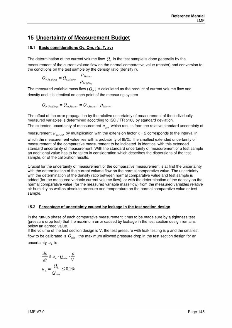
Reference Manual LMF
LMF V7.0 Page 145
15 Uncertainty of Measurement Budget
15.1 Basic considerations Qv, Qm, r(p, T, xv)
The determination of the current volume flow vQ in the test sample is done generally by the
measurement of the current volume flow on the normal comparative value (master) and conversion to the conditions on the test sample by the density ratio (density r).
üfling
Master
Mastervüflingv QQPr
,Pr,ρ
ρ⋅=
The measured variable mass flow ( mQ ) is calculated as the product of current volume flow and
density and it is identical on each point of the measuring system
MasterMastervMastermüflingm QQQ ρ⋅== ,,Pr, The effect of the error propagation by the relative uncertainty of measurement of the individually measured variables is determined according to ISO / TR 5168 by standard deviation.
The extended uncertainty of measurement gesu which results from the relative standard uncertainty of
measurement stdgesu , by multiplication with the extension factor k = 2 corresponds to the interval in
which the measurement value lies with a probability of 95%. The smallest extended uncertainty of measurement of the comparative measurement to be indicated is identical with this extended standard uncertainty of measurement. With the standard uncertainty of measurement of a test sample an additional value has to be taken in consideration which describes the dispersions of the test sample, or of the calibration results. Crucial for the uncertainty of measurement of the comparative measurement is at first the uncertainty with the determination of the current volume flow on the normal comparative value. The uncertainty with the determination of the density ratio between normal comparative value and test sample is added (for the measured variable current volume flow), or with the determination of the density on the normal comparative value (for the measured variable mass flow) from the measured variables relative air humidity as well as absolute pressure and temperature on the normal comparative value or test sample.
15.2 Percentage of uncertainty caused by leakage in the test section design
In the run-up phase of each comparative measurement it has to be made sure by a tightness test (pressure drop test) that the maximum error caused by leakage in the test section design remains below an agreed value. If the volume of the test section design is V, the test pressure with leak testing is p and the smallest
flow to be calibrated is minQ , the maximum allowed pressure drop in the test section design for an
uncertainty Lu is
V
pQu
dt
dpL ⋅⋅≤ min
%1,0min
≤=Q
Qu L
L
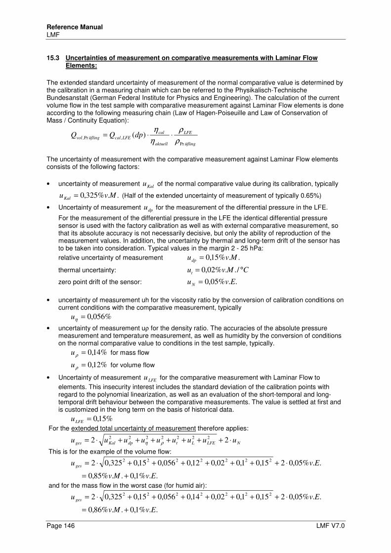
Reference Manual LMF
Page 146 LMF V7.0
15.3 Uncertainties of measurement on comparative measurements with Laminar Flow Elements:
The extended standard uncertainty of measurement of the normal comparative value is determined by the calibration in a measuring chain which can be referred to the Physikalisch-Technische Bundesanstalt (German Federal Institute for Physics and Engineering). The calculation of the current volume flow in the test sample with comparative measurement against Laminar Flow elements is done according to the following measuring chain (Law of Hagen-Poiseuille and Law of Conservation of Mass / Continuity Equation):
üfling
LFE
aktuell
cal
LFEcalüflingvol dpQQPr
,Pr, )(ρ
ρ
η
η⋅⋅=
The uncertainty of measurement with the comparative measurement against Laminar Flow elements consists of the following factors:
• uncertainty of measurement Kalu of the normal comparative value during its calibration, typically
..%325,0 MvuKal = (Half of the extended uncertainty of measurement of typically 0.65%)
• Uncertainty of measurement dpu for the measurement of the differential pressure in the LFE.
For the measurement of the differential pressure in the LFE the identical differential pressure sensor is used with the factory calibration as well as with external comparative measurement, so that its absolute accuracy is not necessarily decisive, but only the ability of reproduction of the measurement values. In addition, the uncertainty by thermal and long-term drift of the sensor has to be taken into consideration. Typical values in the margin 2 - 25 hPa:
relative uncertainty of measurement ..%15,0 Mvudp =
thermal uncertainty: CMvut °= /..%02,0
zero point drift of the sensor: ..%05,0 EvuN =
• uncertainty of measurement uh for the viscosity ratio by the conversion of calibration conditions on
current conditions with the comparative measurement, typically
%056,0=ηu
• uncertainty of measurement uρ for the density ratio. The accuracies of the absolute pressure measurement and temperature measurement, as well as humidity by the conversion of conditions on the normal comparative value to conditions in the test sample, typically.
%14,0=ρu for mass flow
%12,0=ρu for volume flow
• Uncertainty of measurement LFEu for the comparative measurement with Laminar Flow to
elements. This insecurity interest includes the standard deviation of the calibration points with regard to the polynomial linearization, as well as an evaluation of the short-temporal and long-temporal drift behaviour between the comparative measurements. The value is settled at first and is customized in the long term on the basis of historical data.
%15,0=LFEu
For the extended total uncertainty of measurement therefore applies:
NLFELtdpKalges uuuuuuuuu ⋅+++++++⋅= 222222222
ρη
This is for the example of the volume flow:
..%1,0..%85,0
..%05,0215,01,002,012,0056,015,0325,022222222
EvMv
Evu ges
+=
⋅+++++++⋅=
and for the mass flow in the worst case (for humid air):
..%1,0..%86,0
..%05,0215,01,002,014,0056,015,0325,022222222
EvMv
Evu ges
+=
⋅+++++++⋅=
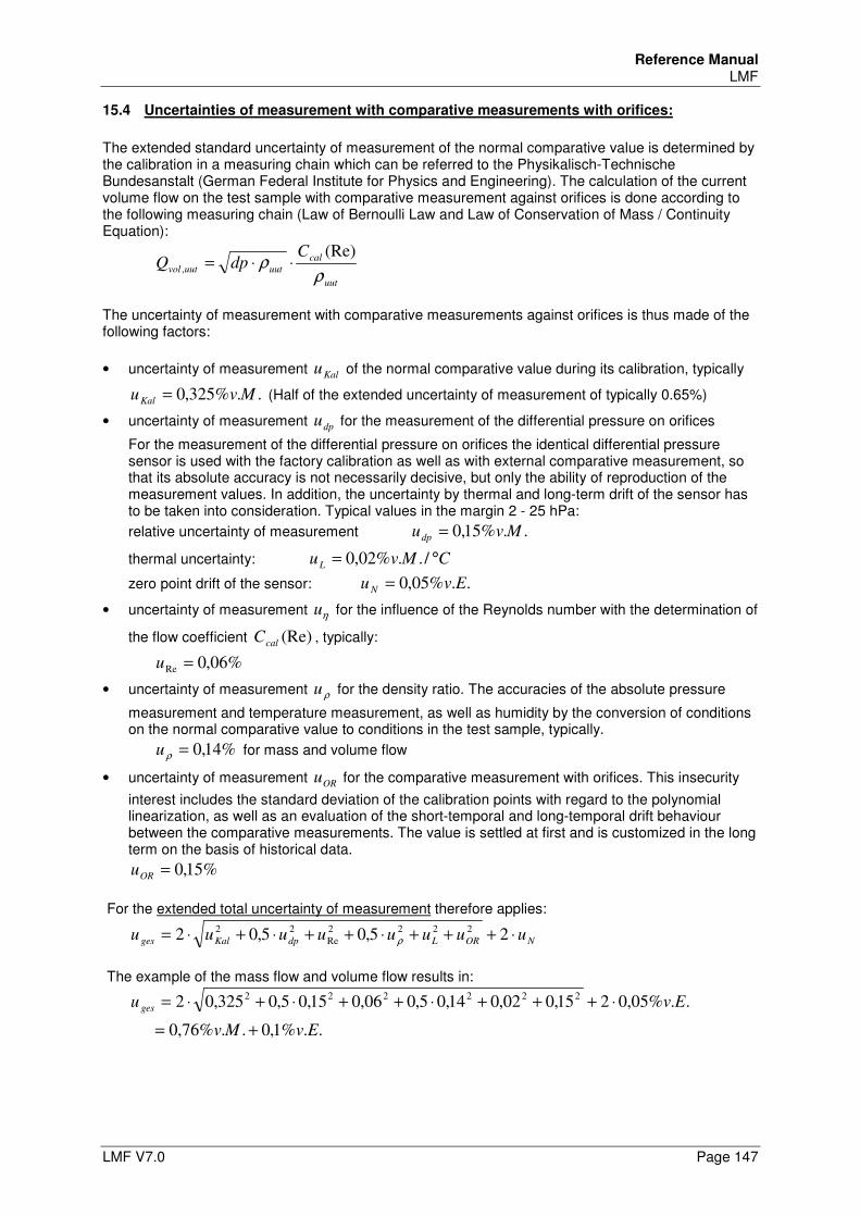
Reference Manual LMF
LMF V7.0 Page 147
15.4 Uncertainties of measurement with comparative measurements with orifices:
The extended standard uncertainty of measurement of the normal comparative value is determined by the calibration in a measuring chain which can be referred to the Physikalisch-Technische Bundesanstalt (German Federal Institute for Physics and Engineering). The calculation of the current volume flow on the test sample with comparative measurement against orifices is done according to the following measuring chain (Law of Bernoulli Law and Law of Conservation of Mass / Continuity Equation):
uut
cal
uutuutvol
CdpQ
ρρ
(Re), ⋅⋅=
The uncertainty of measurement with comparative measurements against orifices is thus made of the following factors:
• uncertainty of measurement Kalu of the normal comparative value during its calibration, typically
..%325,0 MvuKal = (Half of the extended uncertainty of measurement of typically 0.65%)
• uncertainty of measurement dpu for the measurement of the differential pressure on orifices
For the measurement of the differential pressure on orifices the identical differential pressure sensor is used with the factory calibration as well as with external comparative measurement, so that its absolute accuracy is not necessarily decisive, but only the ability of reproduction of the measurement values. In addition, the uncertainty by thermal and long-term drift of the sensor has to be taken into consideration. Typical values in the margin 2 - 25 hPa:
relative uncertainty of measurement ..%15,0 Mvudp =
thermal uncertainty: CMvuL °= /..%02,0
zero point drift of the sensor: ..%05,0 EvuN =
• uncertainty of measurement ηu for the influence of the Reynolds number with the determination of
the flow coefficient (Re)calC , typically:
%06,0Re =u
• uncertainty of measurement ρu for the density ratio. The accuracies of the absolute pressure
measurement and temperature measurement, as well as humidity by the conversion of conditions on the normal comparative value to conditions in the test sample, typically.
%14,0=ρu for mass and volume flow
• uncertainty of measurement ORu for the comparative measurement with orifices. This insecurity
interest includes the standard deviation of the calibration points with regard to the polynomial linearization, as well as an evaluation of the short-temporal and long-temporal drift behaviour between the comparative measurements. The value is settled at first and is customized in the long term on the basis of historical data.
%15,0=ORu
For the extended total uncertainty of measurement therefore applies:
NORLdpKalges uuuuuuuu ⋅+++⋅++⋅+⋅= 25,05,022222
Re
22
ρ
The example of the mass flow and volume flow results in:
..%1,0..%76,0
..%05,0215,002,014,05,006,015,05,0325,02222222
EvMv
Evu ges
+=
⋅+++⋅++⋅+⋅=
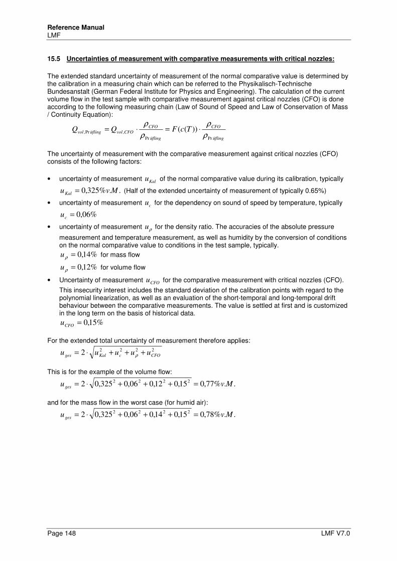
Reference Manual LMF
Page 148 LMF V7.0
15.5 Uncertainties of measurement with comparative measurements with critical nozzles:
The extended standard uncertainty of measurement of the normal comparative value is determined by the calibration in a measuring chain which can be referred to the Physikalisch-Technische Bundesanstalt (German Federal Institute for Physics and Engineering). The calculation of the current volume flow in the test sample with comparative measurement against critical nozzles (CFO) is done according to the following measuring chain (Law of Sound of Speed and Law of Conservation of Mass / Continuity Equation):
üfling
CFO
üfling
CFO
CFOvolüflingvol TcFQQPrPr
,Pr, ))((ρ
ρ
ρ
ρ⋅=⋅=
The uncertainty of measurement with the comparative measurement against critical nozzles (CFO) consists of the following factors:
• uncertainty of measurement Kalu of the normal comparative value during its calibration, typically
..%325,0 MvuKal = (Half of the extended uncertainty of measurement of typically 0.65%)
• uncertainty of measurement cu for the dependency on sound of speed by temperature, typically
%06,0=cu
• uncertainty of measurement ρu for the density ratio. The accuracies of the absolute pressure
measurement and temperature measurement, as well as humidity by the conversion of conditions on the normal comparative value to conditions in the test sample, typically.
%14,0=ρu for mass flow
%12,0=ρu for volume flow
• Uncertainty of measurement CFOu for the comparative measurement with critical nozzles (CFO).
This insecurity interest includes the standard deviation of the calibration points with regard to the polynomial linearization, as well as an evaluation of the short-temporal and long-temporal drift behaviour between the comparative measurements. The value is settled at first and is customized in the long term on the basis of historical data.
%15,0=CFOu
For the extended total uncertainty of measurement therefore applies:
2222
2 CFOcKalges uuuuu +++⋅= ρ
This is for the example of the volume flow:
..%77,015,012,006,0325,022222
Mvu ges =+++⋅=
and for the mass flow in the worst case (for humid air):
..%78,015,014,006,0325,022222
Mvu ges =+++⋅=
Reference Manual LMF
LMF V7.0 Page 149
16 PLC Interface
The PLC interface is for remote control of automatic test procedures. Besides, it is unimportant for the LMF whether it communicates with a classical programmable logic controller (PLC), a PC, or with a manual remote control. This chapter informs about: • Overview of test steps and functions (paragraph 16.1) • Detailed information for the particular test steps (paragraph 16.2) • overview and explanation of the signals used for control (paragraph 16.3) • configuration of the interface (allocation of the signals, paragraph 16.4) • schematic signal functions (paragraph 16.5) Note The functionality of the PLC interface can be flexibly adapted through appropriate configuration to meet different needs, and testing applications. In this chapter only the simple basic flow is described . The example is about a system in which a regulated test pressure and a flow rate is measured and evaluated. About your application-specific features, please refer to the “Operating Instructions and System Configuration" of your system.
16.1 Overview of test steps and procedures
The test schedules are divided in single test steps which are partly an automatic or dependent sequence of parameter settings, events or signals. In standard cases, the sequence of the test steps is executed once, at the end of the test sequence result signals are set. Standard test procedure The standard test procedure typically looks as follows: • Setting the signal "Ready" • Wait for PLC start • Program selection based on the set program signals, possibly evaluate control signals for special
functions (e.g. Zeroing) • If necessary, perform zeroing • Pre-Fill • Fill • Calm • Measure (with continuous monitoring of the testing pressure) • Evaluate result (e.g. mean value of volume flow) • Indicate result on display • Venting • Setting signal “End” • Wait for reset of PLC start • Resetting signal “End” • Setting signal “Ready”
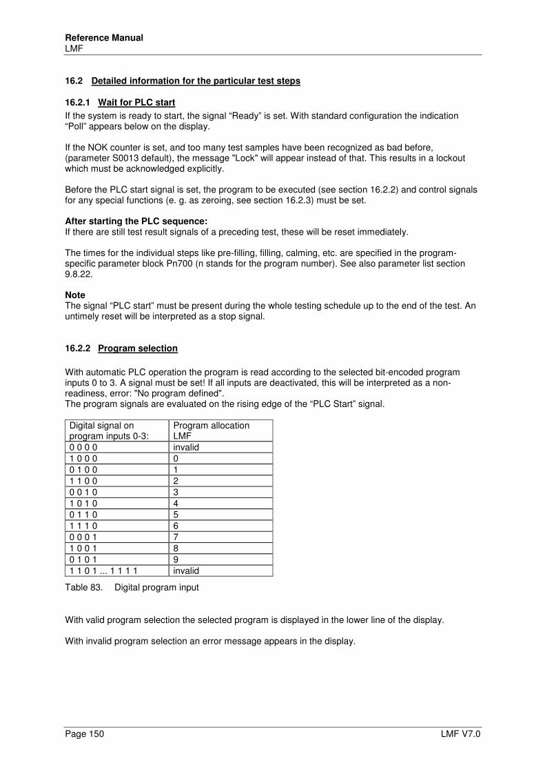
Reference Manual LMF
Page 150 LMF V7.0
16.2 Detailed information for the particular test steps
16.2.1 Wait for PLC start
If the system is ready to start, the signal “Ready” is set. With standard configuration the indication “Poll” appears below on the display. If the NOK counter is set, and too many test samples have been recognized as bad before, (parameter S0013 default), the message "Lock" will appear instead of that. This results in a lockout which must be acknowledged explicitly. Before the PLC start signal is set, the program to be executed (see section 16.2.2) and control signals for any special functions (e. g. as zeroing, see section 16.2.3) must be set. After starting the PLC sequence: If there are still test result signals of a preceding test, these will be reset immediately. The times for the individual steps like pre-filling, filling, calming, etc. are specified in the program-specific parameter block Pn700 (n stands for the program number). See also parameter list section 9.8.22. Note The signal “PLC start” must be present during the whole testing schedule up to the end of the test. An untimely reset will be interpreted as a stop signal.
16.2.2 Program selection
With automatic PLC operation the program is read according to the selected bit-encoded program inputs 0 to 3. A signal must be set! If all inputs are deactivated, this will be interpreted as a non-readiness, error: "No program defined". The program signals are evaluated on the rising edge of the “PLC Start” signal. Digital signal on program inputs 0-3:
Program allocation LMF
0 0 0 0 invalid 1 0 0 0 0 0 1 0 0 1 1 1 0 0 2 0 0 1 0 3 1 0 1 0 4 0 1 1 0 5 1 1 1 0 6 0 0 0 1 7 1 0 0 1 8 0 1 0 1 9 1 1 0 1 ... 1 1 1 1 invalid
Table 83. Digital program input
With valid program selection the selected program is displayed in the lower line of the display. With invalid program selection an error message appears in the display.
Reference Manual LMF
LMF V7.0 Page 151
16.2.3 Nullification
The nullification of differential or gauge pressure sensors is carried out it the signal “Zero” was set with the rising edge of the signal “PLC Start”. The separate settling times before zeroing are set in the parameters S1100 to S1102. Parameters S1101 and S1102 only play a role, of not all nullable sensors can be zeroed together in a group. See also parameter list sections 9.7.5 and 9.7.12. While zeroing the signal "Zero Active" is set. Zeroing can not be terminated prematurely by the signal "GO". After zeroing the signal "Zero Active" is withdrawn.
16.2.4 Pre-Fill
During the fill the signal "Fill" is set. The pressure is adjusted. The selected program is displayed on the left side below, the indication "Pfil". The duration of the phase “pre-fill” is determined by parameter Pn710. The phase “fill” can be quit just as the phase “display result” by the signal “Go” prematurely before the respective waiting period. This may make sense, for example, if the phase “fill” shall be quit by an event which is evaluated by the superior control. If the waiting period is set to 0 or has already run off, the signal “Go” has no effect.
16.2.5 Fill
During the fill the signal "Fill" is set. The selected program is displayed on the left side below, the indication "Fill" on the right side. The duration of the phase “Fill” is determined by parameter Pn711. The phase “fill” can be terminated prematurely by the signal "GO". If the waiting period is set to 0 or has already run off, the signal “Go” has no effect. At the end of the phase “fill” the signal “fill” will be reset.
16.2.6 Calm
Display as above, only with the indication "Calm" on the right side below. Signal "calm" set. The duration of the phase “Calm” is determined by parameter Pn712. The phase “Calm” can be terminated prematurely by the signal "GO". At the end of the phase “Calm” the signal “Calm” will be reset.
16.2.7 Measurement
Signal “Measure” is set. Usually the relevant variables (i.e. in the example chosen the regulated test pressure and the resulting volume flow) and the measurement time are displayed. The duration of the phase “Measure” is defined by the parameter Pn701. The testing pressure is continuously monitored. If the test pressure is outside a parameterized value range, the measurement is terminated prematurely. The average value of the variable relevant to the rating of the specimen is evaluated.
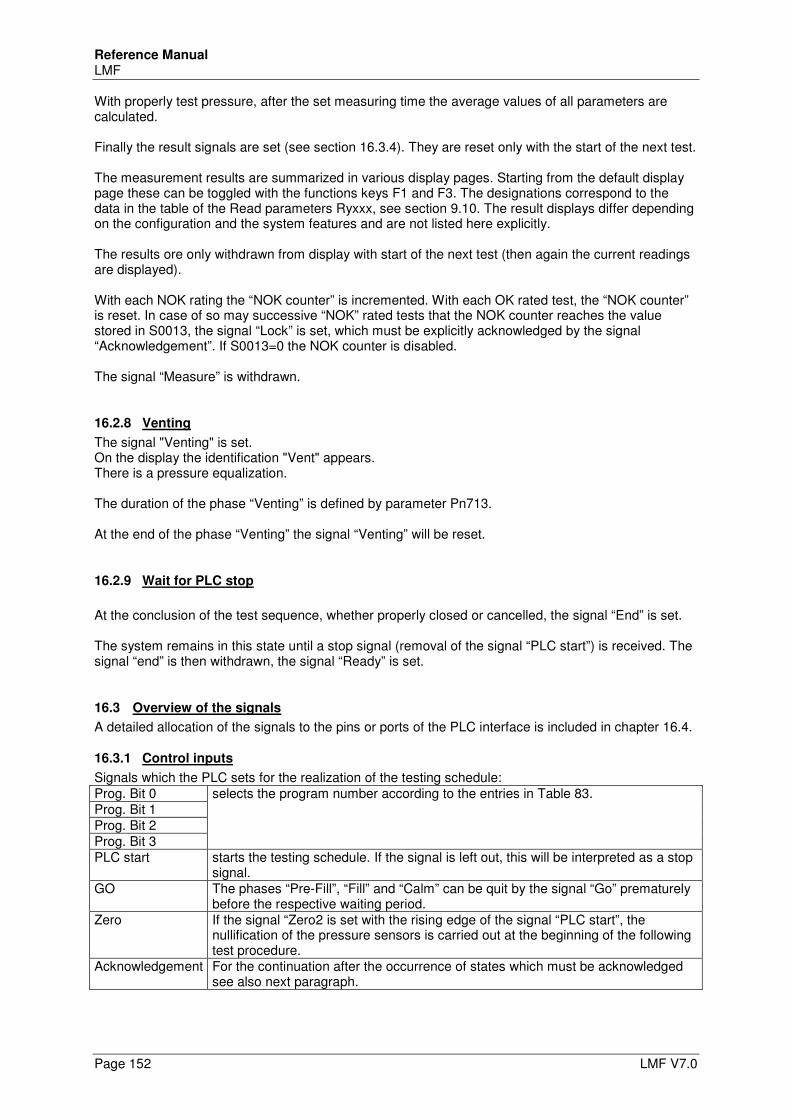
Reference Manual LMF
Page 152 LMF V7.0
With properly test pressure, after the set measuring time the average values of all parameters are calculated. Finally the result signals are set (see section 16.3.4). They are reset only with the start of the next test. The measurement results are summarized in various display pages. Starting from the default display page these can be toggled with the functions keys F1 and F3. The designations correspond to the data in the table of the Read parameters Ryxxx, see section 9.10. The result displays differ depending on the configuration and the system features and are not listed here explicitly. The results ore only withdrawn from display with start of the next test (then again the current readings are displayed). With each NOK rating the “NOK counter” is incremented. With each OK rated test, the “NOK counter” is reset. In case of so may successive “NOK” rated tests that the NOK counter reaches the value stored in S0013, the signal “Lock” is set, which must be explicitly acknowledged by the signal “Acknowledgement”. If S0013=0 the NOK counter is disabled. The signal “Measure” is withdrawn.
16.2.8 Venting
The signal "Venting" is set. On the display the identification "Vent" appears. There is a pressure equalization. The duration of the phase “Venting” is defined by parameter Pn713. At the end of the phase “Venting” the signal “Venting” will be reset.
16.2.9 Wait for PLC stop
At the conclusion of the test sequence, whether properly closed or cancelled, the signal “End” is set. The system remains in this state until a stop signal (removal of the signal “PLC start”) is received. The signal “end” is then withdrawn, the signal “Ready” is set.
16.3 Overview of the signals
A detailed allocation of the signals to the pins or ports of the PLC interface is included in chapter 16.4.
16.3.1 Control inputs
Signals which the PLC sets for the realization of the testing schedule: Prog. Bit 0 selects the program number according to the entries in Table 83. Prog. Bit 1 Prog. Bit 2 Prog. Bit 3 PLC start starts the testing schedule. If the signal is left out, this will be interpreted as a stop
signal. GO The phases “Pre-Fill”, “Fill” and “Calm” can be quit by the signal “Go” prematurely
before the respective waiting period. Zero If the signal “Zero2 is set with the rising edge of the signal “PLC start”, the
nullification of the pressure sensors is carried out at the beginning of the following test procedure.
Acknowledgement For the continuation after the occurrence of states which must be acknowledged see also next paragraph.
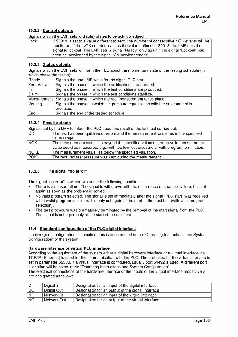
Reference Manual LMF
LMF V7.0 Page 153
16.3.2 Control outputs
Signals which the LMF sets to display states to be acknowledged. Lock If S0013 is set to a value different to zero, the number of consecutive NOK events will be
monitored. If the NOK counter reaches the value defined in S0013, the LMF sets the signal to lockout. The LMF sets a signal “Ready” only again if the signal “Lockout” has been acknowledged by the signal “Acknowledgement”.
16.3.3 Status outputs
Signals which the LMF sets to inform the PLC about the momentary state of the testing schedule (in which phase the test is): Ready Signals that the LMF waits for the signal PLC start Zero Active Signals the phase in which the nullification is performed. Fill Signals the phase in which the test conditions are produced. Calm Signals the phase in which the test conditions stabilize. Measurement Signals the phase in which the real measurement takes place. Venting Signals the phase, in which the pressure equalization with the environment is
produced. End Signals the end of the testing schedule.
16.3.4 Result outputs
Signals set by the LMF to inform the PLC about the result of the last test carried out. OK The test has been quit free of errors and the measurement value lies in the specified
value range. NOK The measurement value lies beyond the specified valuation, or no valid measurement
value could be measured, e.g., with too low test pressure or with program termination. NOKL The measurement value lies below the specified valuation. POK The required test pressure was kept during the measurement.
16.3.5 The signal “no error”
The signal “no error” is withdrawn under the following conditions: • There is a sensor failure. The signal is withdrawn with the occurrence of a sensor failure. It is set
again as soon as the problem is solved. • No valid program selected. The signal is set immediately after the signal “PLC start” was received
with invalid program selection. It is only set again at the start of the next test (with valid program selection).
• The test procedure was prematurely terminated by the removal of the start signal from the PLC. The signal is set again only at the start of the next test.
16.4 Standard configuration of the PLC digital interface
If a divergent configuration is specified, this is documented in the “Operating Instructions and System Configuration” of the system. Hardware interface or virtual PLC interface According to the equipment of the system either a digital hardware interface or a virtual interface via TCP/IP (Ethernet) is used for the communication with the PLC. The port used for the virtual interface is set in parameter S9500. If a virtual interface is configured, usually port 54492 is used. A different port allocation will be given in the “Operating Instructions and System Configuration”. The electrical connections of the hardware interface or the inputs of the virtual interface respectively are designated as follows: DI Digital In Designation for an input of the digital interface DO Digital Out Designation for an output of the digital interface NI Network In Designation for an input of the virtual interface NO Network Out Designation for an output of the virtual interface
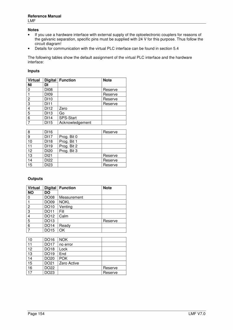
Reference Manual LMF
Page 154 LMF V7.0
Notes
• If you use a hardware interface with external supply of the optoelectronic couplers for reasons of the galvanic separation, specific pins must be supplied with 24 V for this purpose. Thus follow the circuit diagram!
• Details for communication with the virtual PLC interface can be found in section 5.4 The following tables show the default assignment of the virtual PLC interface and the hardware interface: Inputs Virtual Digital Function Note
NI DI
0 DI08 Reserve 1 DI09 Reserve 2 DI10 Reserve 3 DI11 Reserve 4 DI12 Zero 5 DI13 Go 6 DI14 SPS-Start 7 DI15 Acknowledgement 8 DI16 Reserve 9 DI17 Prog. Bit 0 10 DI18 Prog. Bit 1 11 DI19 Prog. Bit 2 12 DI20 Prog. Bit 3 13 DI21 Reserve 14 DI22 Reserve 15 DI23 Reserve Outputs Virtual Digital Function Note
NO DO
0 DO08 Measurement 1 DO09 NOKL 2 DO10 Venting 3 DO11 Fill 4 DO12 Calm 5 DO13 Reserve 6 DO14 Ready 7 DO15 OK 10 DO16 NOK 11 DO17 no error 12 DO18 Lock 13 DO19 End 14 DO20 POK 15 DO21 Zero Active 16 DO22 Reserve 17 DO23 Reserve
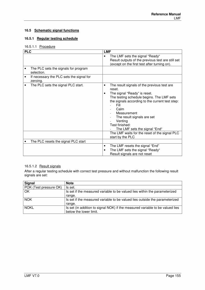
Reference Manual LMF
LMF V7.0 Page 155
16.5 Schematic signal functions
16.5.1 Regular testing schedule
16.5.1.1 Procedure
PLC LMF
• The LMF sets the signal “Ready“ Result outputs of the previous test are still set (except on the first test after turning on).
• The PLC sets the signals for program selection.
• If necessary the PLC sets the signal for zeroing.
• The PLC sets the signal PLC start. • The result signals of the previous test are reset.
• The signal “Ready” is reset. The testing schedule begins. The LMF sets the signals according to the current test step: - Fill - Calm - Measurement - The result signals are set - Venting Test finished: - The LMF sets the signal “End“
The LMF waits for the reset of the signal PLC start by the PLC
• The PLC resets the signal PLC start
• The LMF resets the signal “End” • The LMF sets the signal “Ready“
Result signals are not reset
16.5.1.2 Result signals
After a regular testing schedule with correct test pressure and without malfunction the following result signals are set: Signal Note
POK (Test pressure OK) Is set. OK Is set if the measured variable to be valued lies within the parameterized
range. NOK Is set if the measured variable to be valued lies outside the parameterized
range. NOKL Is set (in addition to signal NOK) if the measured variable to be valued lies
below the lower limit.
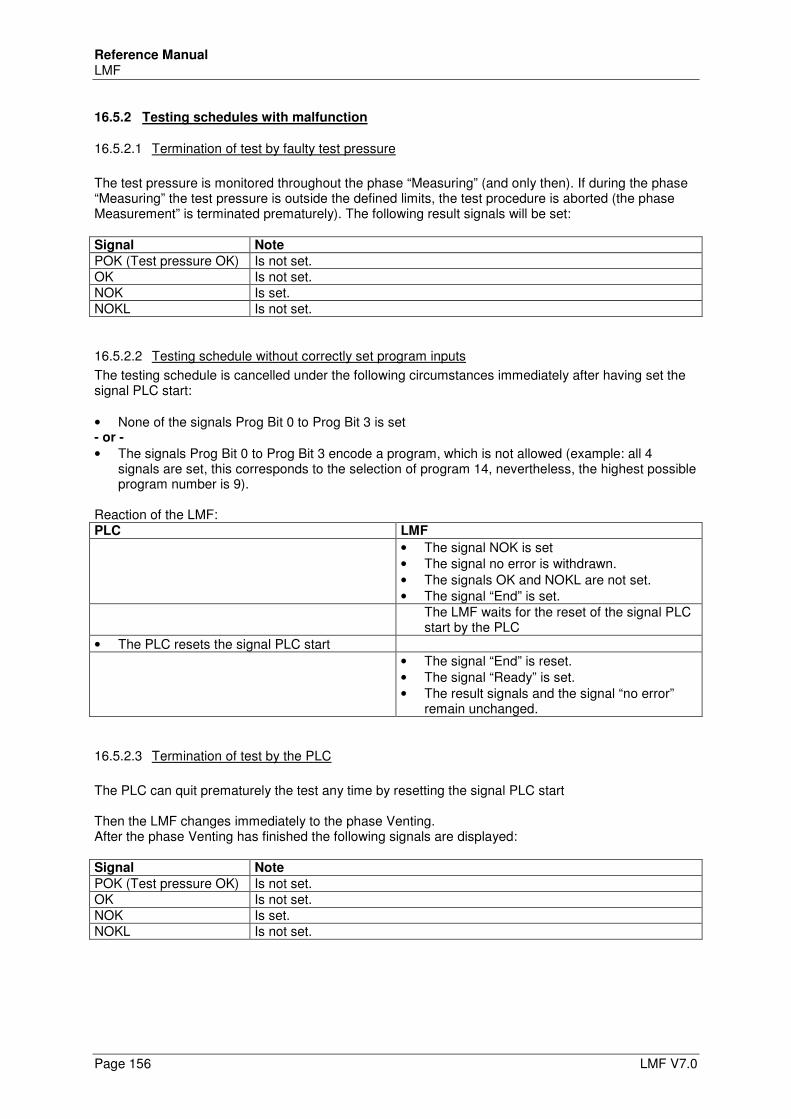
Reference Manual LMF
Page 156 LMF V7.0
16.5.2 Testing schedules with malfunction
16.5.2.1 Termination of test by faulty test pressure
The test pressure is monitored throughout the phase “Measuring” (and only then). If during the phase “Measuring” the test pressure is outside the defined limits, the test procedure is aborted (the phase Measurement” is terminated prematurely). The following result signals will be set: Signal Note
POK (Test pressure OK) Is not set. OK Is not set. NOK Is set. NOKL Is not set.
16.5.2.2 Testing schedule without correctly set program inputs
The testing schedule is cancelled under the following circumstances immediately after having set the signal PLC start: • None of the signals Prog Bit 0 to Prog Bit 3 is set - or -
• The signals Prog Bit 0 to Prog Bit 3 encode a program, which is not allowed (example: all 4 signals are set, this corresponds to the selection of program 14, nevertheless, the highest possible program number is 9).
Reaction of the LMF: PLC LMF
• The signal NOK is set • The signal no error is withdrawn. • The signals OK and NOKL are not set. • The signal “End” is set.
The LMF waits for the reset of the signal PLC start by the PLC
• The PLC resets the signal PLC start
• The signal “End” is reset. • The signal “Ready” is set. • The result signals and the signal “no error”
remain unchanged.
16.5.2.3 Termination of test by the PLC
The PLC can quit prematurely the test any time by resetting the signal PLC start Then the LMF changes immediately to the phase Venting. After the phase Venting has finished the following signals are displayed: Signal Note
POK (Test pressure OK) Is not set. OK Is not set. NOK Is set. NOKL Is not set.