Embed Size (px)
Citation preview
Geotechnical Engineering Research Laboratory Samuel G. Paikowsky, Sc.D. One University Avenue Professor Lowell, Massachusetts 01854 Tel: (978) 934-2277 Fax: (978) 934-3046 e-mail: [email protected] web site: http://geores.caeds.eng.uml.edu DEPARTMENT OF CIVIL AND ENVIRONMENTAL ENGINEERING
Load and Resistance Factor Design (LRFD) for Dynamic Analysis of Deep Foundations
By Samuel G. Paikowsky
To be published in the 15th International Conference on Soil Mechanics & Foundation Engineering
August 2001 Istanbul, Turkey
Vol. 2, pp. 981-984
1 INTRODUCTION
National Cooperative Highway Research Program, project, NCHRP 24-17, “LRFD Deep Foundations Design” was initiated to provide recommended revisions to the driven pile and drilled shaft portions of section 10 of AASHTO Specifications. The cur-rent AASHTO specifications as well as other existing codes based on Load and Resistance Factor Design (LRFD) principles were developed with insufficient data utilizing mostly back-calculated factors. The main challenges of the project are there-fore: (a) Compilation of large, high quality databases and (b) Framework for a procedure and data management to enable: (i) LRFD parameter evaluation and (ii) Future updates. These chal-lenges require the reorganization of the factors following the de-sign - construction - quality control sequence (i.e. independence in resistance factors according to the chronological stage and the evaluation procedure). The project team, headed by the author, is divided into three major groups dealing with static analyses (Univ. of Florida and the Univ. of Massachusetts, Lowell), prob-abilistic approaches and structural analyses (Univ. of Maryland), and dynamic analyses (Univ. of Massachusetts, Lowell). The present paper provides a condensed summary of the LRFD resis-tance parameters developed for use with driven pile capacity evaluation based on dynamic measurements. A more complete presentation is provided by Paikowsky & Stenersen (2000). A final report of the project is expected to be completed by Sum-mer 2000.
2 PD/LT 2000 DATABASE
The database PD/LT2000 contains information related to 210 driven piles that have been statically load tested to failure and dynamically monitored during driving and/or restrike (403 ana-lyzed measurements). PD/LT2000 is comprised of the integra-tion of databases PD/LT (Paikowsky et al. 1994) and PD/LT2
(Paikowsky & LaBelle, 1994) with expansion by an additional 57 pile cases (Stenersen, 2000). The data of PD/LT2000 were carefully examined and analyzed following procedures described by Paikowsky et al. 1994, resulting in detailed static and dy-namic pile capacity evaluations. Paikowsky & Stenersen (2000) presents a summary of the data contained in PD/LT2000 broken down according to site location and soil type, pile type and ca-pacity, driving behavior and time of driving.
3 REFERENCE STATIC CAPACITY
The dynamic methods are assessed by comparing the pile capac-ity of the evaluated method with a reference static capacity of the pile. The determination of the pile’s static capacity based on load displacement relations is not unique. The test results depend on the load testing procedures and the applied interpretation method, often being subjective. Examination of these factors and their influence on the reference static capacity was carried out as a prerequisite for the calibration of the dynamic methods.
Past work (Paikowsky et al. 1994) have resorted to a “repre-sentative” static pile capacity based on the assessment of five in-terpretation methods; Davisson’s Criterion (Davisson, 1972), Shape of Curve (similar to the procedure proposed by Butler and Hoy, 1977), Limiting Total Settlement to 25.4 mm and to 0.1B (Terzaghi, 1942), and the DeBeer log-log method (DeBeer, 1970). A single representative capacity value was then calculated for the analyzed case as the average of the methods considered relevant (i.e. provided reasonable value). The development of a framework for specifications requires that the evaluated resis-tance factors be based on an objective, repetitive procedure. Pai-kowsky & Stenersen (2000) have shown that Davisson’s crite-rion was found to perform the best overall with a mean of 1.018 and standard deviation of 0.101 (186 cases) when compared with the representative value. Davisson's criterion was therefore cho-sen as the single method to be used when analyzing load-displacement curves. The method was also found to perform well
Load and Resistance Factor Design (LRFD) for Dynamic Analysis of Deep Foundations
La Méthode de "Facteurs de Charges et de Résistances" pour les dondations profondes S.G. PAIKOWSKY, University of Massachusetts Lowell, Lowell, MA, U.S.A.
ABSTRACT: An effort supported by the NCHRP is aimed at rewriting AASHTO Deep Foundation Specifications. The AASHTO specifications are traditionally observed on all federally aided projects and generally viewed as a National code of the US Highway practice. The new code is based on Load and Resistance Factor Design (LRFD) principles with resistance factors obtained from a probabilistic analysis of data. The currently developed databases relate to axial capacity of single driven piles and drilled shafts. For the dynamic evaluation of driven piles, a database (PD/LT2000) containing information related to 210 piles and 403 dynamic meas-urements was compiled. Details are provided for the performance of the various dynamic analysis methods when compared to static load testing to failure. The parameters that control the accuracy of the predictions are analyzed. Statistical analyses are then utilized for the development of the recommended resistance factors to be used in the new specifications. RÉSUMÉ: Ce projet, supporté par NCHRP a pour but de re-écrire les Spécifications AASHTO pour les fondations profondes. Les Spécifications AASHTO sont utilisées sur tous les projets payés fédérallement et sont acceptées comme code national pour le trans-port aux Etats Unis. Le nouveau code se base sur les principes de la méthode de “Facteurs de Charges et de Résistances” où ces der-niers facteurs sont obtenus par l’analyse de probabilité. Les banques de données qui sont developpées donnent la capacité de pieux en-foncés et de caissons forés. Pour l’évaluation dynamique des pieux enfoncés, une banque de donnée (PD/LT2000) a été développée pour 210 pieux utilisant 403 mesures dynamiques.. Les diverses méthodes d’analyse dynamique sont comparées aux résultats de tests statiques de pieux. Les paramètres qui controlent la précision de ces prédictions sont analysés. Finallement, l’analyse de probabilité est utilisée pour développer les Facteurs de Résistance recommendés pour les nouvelles Spécifications.
for piles exceeding a diameter of 610mm (examined through 30 pile cases).
The influence of the static load testing procedure (loading rate) on the designated pile capacity was examined in two ways: (i) Two detailed case histories in which piles were tested using three types of static load testing procedures varying in time form 45 hours to about 15 minutes. The interpretation of the load-displacement relationships in both cases suggested that the test type had an insignificant influence on the pile capacity, (refer-ring to a failure criterion irrespective of the displacement). (ii) The effect of the test type was further investigated utilizing a database containing information related to 75 piles tested under slow maintained and static-cyclic load testing procedures pre-sented by Paikowsky et al. (1999). The obtained relations and the associated statistical information (mean = 0.930, standard devia-tion = 0.136) suggest that the applied pseudo-static load rate has no significant influence on the static pile capacity.
These evaluations led to the conclusions that Davisson’s pile failure criterion can be used as a method to determine the refer-ence static pile capacity irrespective of the static load-testing procedure.
4 THE CHOSEN DYNAMIC METHODS AND THEIR CONTROLLING PARAMETERS
4.1 Overview Prior to detailed analyses leading to the determination of resis-tance factors, two components must be established: (a) the type of the dynamic methods to be evaluated and (b) the conditions under which these methods need to be examined.
4.2 Methods of Analysis The major available dynamic methods for evaluating pile capac-ity can be categorized according to the project stage (i.e. design vs. construction) and the need for data obtained through dynamic measurements. Wave Equation Analysis Program (WEAP, see Smith 1960 and Gobel et al. 1976) was considered for the design stage. Engineering News Record (ENR, see Wellington 1892), Gates equation (Gates 1957) and FHWA modified Gates equa-tion (FHWA 1988) were the dynamic equations considered for analysis during construction in which dynamic measurements are not available. The incorporation of dynamic equations and WEAP reflects the state of practice in USA highway construc-tion and hence need to be addressed for the specifications regard-less of the existing knowledge concerning their effectiveness.
The methods that require dynamic measurements can be broadly categorized as those that utilize a simplified analysis of an instantaneous pile capacity evaluation for each hammer blow, and those that require elaborate calculations (i.e. signal match-ing, see Goble et al. 1970), traditionally carried out in the office.
Due to the vital importance of static pile capacity evaluation during driving, a short discussion of the field methods follows. The Case method (Goble et al., 1970 & Rausche et al., 1975) is often used in field evaluations, as it is built into Pile Dynamics Inc.’s Pile Driving Analyzer (PDA), the most commonly used in the USA. The method is based on a simplified pile and soil be-havior assumptions (free end and plastic soil), resulting in a closed form solution related to the impact and its reflection from the tip. With the years, the method evolved to be implemented into at least five different variations (GRL, 1999). The Case method utilizes a damping coefficient (Jc) that is assumed to be associated with soil type. The Case-damping coefficient was in-vestigated through a back calculation (to match the measured static capacity). The results show no correlation between the soil type and the Case damping coefficient. The recommended prac-tice is the use of the method based on a specific site/area calibra-tion (GRL 1999), has proven to be effective locally; e.g. in Bos-ton (GTR 1997, 1998) and in Florida (McVay et al. 2000).
As no generic conditions exist for the use of the Case method, international or national calibrations are unrealistic. In addition, as the projection of local calibration (of good experience and practice) beyond their geographical location may be unwise and/or unsafe, the Case method was excluded from the examined dynamic analyses.
The Energy Approach is a simplified method, uses basic en-ergy relations in conjunction with dynamic measurements to de-termine pile capacity. The concept was presented by Paikowsky (1982) and was examined on a limited scale by Paikowsky & Chernauskas (1992). Extensive studies of the Energy Approach method were carried out by Paikowsky et al. (1994), and Pai-kowsky & LaBelle (1994). The underlying concept of this ap-proach is the energy balance between the total energy delivered to the pile and the work done by the pile/soil system. The basic Energy Approach equation is:
( )2
max
max
SetDSet
ER u −
+= (1)
where Ru = maximum pile resistance, Emax = measured maxi-mum energy delivered to the pile, Dmax = measured maximum pile top displacement, and Set = permanent displacement of the pile at the end of the analyzed blow, or 1/measured blow count. For further details regarding the Energy Approach method see Paikowsky et al. (1994) and Paikowsky (1995).
4.3 The Controlling Parameters Preliminary examination of the parameters controlling the per-formance of the dynamic analyses was carried out prior to a final detailed evaluation of these methods, leading to resistance fac-tors. Such examination influences the sub categorization of the dynamic methods hence, directing the user to utilize the appro-priate resistance factor according to the relevant conditions of the employed method. For example, if soil type is a controlling factor and the accuracy of the signal matching method is largely affected by soil type, evaluation of the method for different soil types will result in the development of resistance factors, de-pending on the soil type. Conversely, if soil type does not control the accuracy of the specific dynamic method, categorization based on soil type is neither desired nor pursued.
The following summary of the controlling parameters exami-nation is based on the rationale and previous studies by Pai-kowsky et al. (1994), Paikowsky (1995) Paikowsky & Cher-nauskas (1996) and Paikowsky & Stenersen (2000). 1. The viscous damping parameters used for modeling the soil is not an intrinsic soil type property. The performance of the signal matching technique cannot therefore be correlated to soil type. This does not preclude other factors associated with soil type to be important (e.g. low driving resistance in soft soils or gain of capacity with time) but suggest that soil type alone is not a con-trolling parameter for which the methods should be calibrated. 2. Due to change of pile capacity with time, the time in which a dynamic test is conducted remains a controlling factor. The dy-namic capacity predictions follow the physical behavior of ca-pacity gain, but do not reflect correctly the actual rate of gain as observed from static measurements. As such, the practical con-trolling factors remain the evaluation of pile capacity during driving and at any time later during restrike without further specifications (for calibration of available data). 3. Soil inertia due to the pile penetration was proven to be a ma-jor controlling parameter (Paikowsky & Chernauskas 1996, Pai-kowsky & Stenersen 2000 and Hajduk et al. 2000). 4. The assumption of a stationary soil is used by the common soil/pile interaction models for the solution of the wave equation. The unaccounted for soil inertia affects therefore the predictions of the dynamic methods through two factors; soil acceleration and the mass of the displaced soil. Soil Acceleration can indi-rectly be accounted for through the driving resistance. Under low
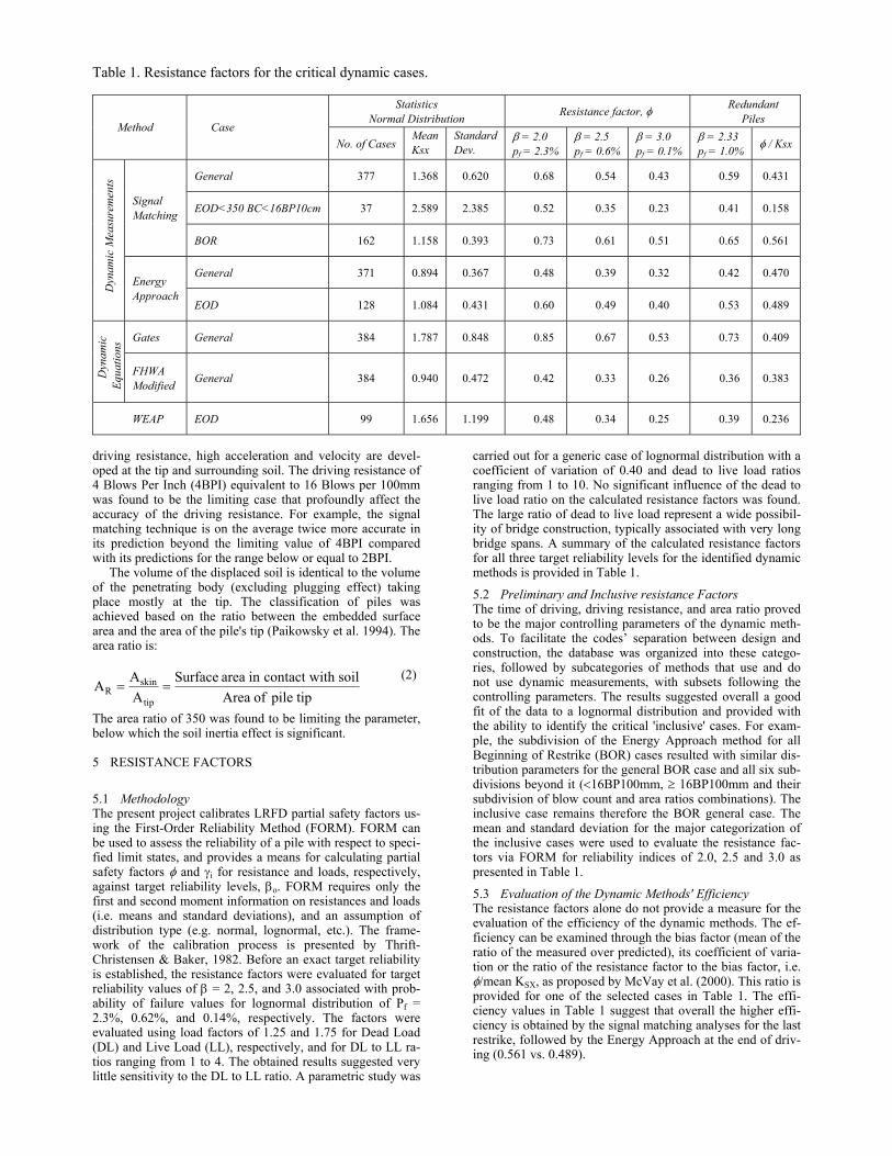
Table 1. Resistance factors for the critical dynamic cases.
Statistics Normal Distribution Resistance factor, φ Redundant
Piles Method Case
No. of Cases Mean Ksx
Standard Dev.
β = 2.0 pf = 2.3%
β = 2.5 pf = 0.6%
β = 3.0 pf = 0.1%
β = 2.33 pf = 1.0% φ / Ksx
General 377 1.368 0.620 0.68 0.54 0.43 0.59 0.431
EOD<350 BC<16BP10cm 37 2.589 2.385 0.52 0.35 0.23 0.41 0.158 Signal Matching
BOR 162 1.158 0.393 0.73 0.61 0.51 0.65 0.561
General 371 0.894 0.367 0.48 0.39 0.32 0.42 0.470
Dyn
amic
Mea
sure
men
ts
Energy Approach
EOD 128 1.084 0.431 0.60 0.49 0.40 0.53 0.489
Gates General 384 1.787 0.848 0.85 0.67 0.53 0.73 0.409
Dyn
amic
Eq
uatio
ns
FHWA Modified General 384 0.940 0.472 0.42 0.33 0.26 0.36 0.383
WEAP EOD 99 1.656 1.199 0.48 0.34 0.25 0.39 0.236
driving resistance, high acceleration and velocity are devel-oped at the tip and surrounding soil. The driving resistance of 4 Blows Per Inch (4BPI) equivalent to 16 Blows per 100mm was found to be the limiting case that profoundly affect the accuracy of the driving resistance. For example, the signal matching technique is on the average twice more accurate in its prediction beyond the limiting value of 4BPI compared with its predictions for the range below or equal to 2BPI.
The volume of the displaced soil is identical to the volume of the penetrating body (excluding plugging effect) taking place mostly at the tip. The classification of piles was achieved based on the ratio between the embedded surface area and the area of the pile's tip (Paikowsky et al. 1994). The area ratio is:
tippileofAreasoilwithcontactinareaSurface
AAA
tip
skinR ==
(2) The area ratio of 350 was found to be limiting the parameter, below which the soil inertia effect is significant.
5 RESISTANCE FACTORS
5.1 Methodology The present project calibrates LRFD partial safety factors us-ing the First-Order Reliability Method (FORM). FORM can be used to assess the reliability of a pile with respect to speci-fied limit states, and provides a means for calculating partial safety factors φ and γi for resistance and loads, respectively, against target reliability levels, βo. FORM requires only the first and second moment information on resistances and loads (i.e. means and standard deviations), and an assumption of distribution type (e.g. normal, lognormal, etc.). The frame-work of the calibration process is presented by Thrift-Christensen & Baker, 1982. Before an exact target reliability is established, the resistance factors were evaluated for target reliability values of β = 2, 2.5, and 3.0 associated with prob-ability of failure values for lognormal distribution of Pf = 2.3%, 0.62%, and 0.14%, respectively. The factors were evaluated using load factors of 1.25 and 1.75 for Dead Load (DL) and Live Load (LL), respectively, and for DL to LL ra-tios ranging from 1 to 4. The obtained results suggested very little sensitivity to the DL to LL ratio. A parametric study was
carried out for a generic case of lognormal distribution with a coefficient of variation of 0.40 and dead to live load ratios ranging from 1 to 10. No significant influence of the dead to live load ratio on the calculated resistance factors was found. The large ratio of dead to live load represent a wide possibil-ity of bridge construction, typically associated with very long bridge spans. A summary of the calculated resistance factors for all three target reliability levels for the identified dynamic methods is provided in Table 1.
5.2 Preliminary and Inclusive resistance Factors The time of driving, driving resistance, and area ratio proved to be the major controlling parameters of the dynamic meth-ods. To facilitate the codes’ separation between design and construction, the database was organized into these catego-ries, followed by subcategories of methods that use and do not use dynamic measurements, with subsets following the controlling parameters. The results suggested overall a good fit of the data to a lognormal distribution and provided with the ability to identify the critical 'inclusive' cases. For exam-ple, the subdivision of the Energy Approach method for all Beginning of Restrike (BOR) cases resulted with similar dis-tribution parameters for the general BOR case and all six sub-divisions beyond it (<16BP100mm, ≥ 16BP100mm and their subdivision of blow count and area ratios combinations). The inclusive case remains therefore the BOR general case. The mean and standard deviation for the major categorization of the inclusive cases were used to evaluate the resistance fac-tors via FORM for reliability indices of 2.0, 2.5 and 3.0 as presented in Table 1.
5.3 Evaluation of the Dynamic Methods' Efficiency The resistance factors alone do not provide a measure for the evaluation of the efficiency of the dynamic methods. The ef-ficiency can be examined through the bias factor (mean of the ratio of the measured over predicted), its coefficient of varia-tion or the ratio of the resistance factor to the bias factor, i.e. φ/mean KSX, as proposed by McVay et al. (2000). This ratio is provided for one of the selected cases in Table 1. The effi-ciency values in Table 1 suggest that overall the higher effi-ciency is obtained by the signal matching analyses for the last restrike, followed by the Energy Approach at the end of driv-ing (0.561 vs. 0.489).
5.4 Recommended resistance Factors No final resistance factors have been approved yet. The cur-rent recommendation is to allow for two sets of resistance fac-tors related to redundant and non-redundant elements. A deep foundation element can be considered redundant when it is a part of a substructure (i.e. pile cap) of five or more piles. Such elements will be assigned with a Pf = 1% and β = 2.3. A non-redundant element will be assigned with a Pf = 0.1% and β = 3.0. For example using the Energy Approach during driving resistance factors of 0.40 and 0.53 will be used for non-redundant and redundant elements, respectively.
6 SUMMARY AND CONCLUSIONS
1. The compilation of a large database allows for the evalua-tion of the dynamic methods and the development of reli-able and logical resistance factors as part of Load and Re-sistance Factor Design (LRFD) methodology.
2. The dynamic methods performance is controlled by the time of driving and soil inertia, which in turn is controlled by the driving resistance and the ratio of the soil displaced by the pile’s tip to the area of the soil along the shaft.
3. The Gates equation and its variation seem to provide a rea-sonable assessment of the pile’s capacity considering the absence of dynamic measurements.
4. The wave equation analysis performs poorly when used for pile capacity evaluation.
5. Signal matching techniques prove to be most reliable for long-term restrike measurements. However, when evalu-ated on efficiency, the application of the signal matching on restrikes seem to be marginal compared to the Energy Approach at the End of Driving (EOD).
6. The Energy Approach provides an exceptionally efficient evaluation of pile capacity during driving.
ACKNOWLEDGEMENTS
The presented research was sponsored by the American Asso-ciation of State Highway and Transportation Officials (AASHTO), under project 24-17, in cooperation with the Federal Highway Administration (FHWA). Drs. Gregory Baecher and Bilal Ayyub from the University of Maryland contributed to section 5.1 and performed the calculations of the presented resistance factors. Dr. Frank Rausche of GRL & Assoc. provided the data pertaining to the evaluation of GRLWEAP. Mr. Nabil Hourani of the MHD kindly translated the abstract to French.
DISCLAIMER
The opinions and conclusions expressed or implied in the pa-per are those of the entities/individuals performing the re-search and are not necessarily those of the Transportation Re-search Board, the National Research Council, the Federal Highway Administration, the American Association of State Highway and Transportation Officials, or the individual states participating in the NCHRP.
REFERENCES
Butler, H.D., & Hoy, H.E. 1977. Users Manual for the Texas Quick-Load Method for Foundation Load Testing. Federal Highway Administration, Office of Development, Report No. FHWA-IP-77-8, Washington, DC.
Davisson, M.T. 1972. High Capacity Piles. Proceedings, Soil Mechanics Lecture Series on Innovations in Foundation Construction. American Society of Civil Engineers, Illinois Section, Chicago, 81-112.
DeBeer, E.E. 1970. Proefondervindellijke bijdrage tot de studie van het grandsdraagvermogen van zand onder funderinger op staal. English version, Geotechnique, Vol. 20, No. 4, 387-411.
FHWA, 1988. FHWA Guide Specifications for Driven Piles. Federal Highway Administration
Gates 1957. Empirical Formula for Predicting Pile Bearing Capacity. Civil Engineering, Vol. 27, No. 3, 65-66.
Goble, G., Likens, G., & Rausche, F. 1970. Dynamic Studies on the Bearing Capacity of Piles – Phase III, Report No. 48. Division of Solid Mechanics, Structures, and Mechanical Design. Case Western Reserve University.
Goble, G. & Rausche, F. 1976. Wave Equation Analysis of Pile Driving-WEAP Program. Vol. 1-4, FHWA #IP-76-14.1 through #IP-76-14.4.
GRL. 1999. Pile-Driving Analyzer, PAK Users Manual. Goble, Rausche, Likins and Associates, Inc.
GTR. 1997. Dynamic Pile Testing Report, Central Artery/Tunnel Project C07D2, I-90/Airport Interchange Arrivals Tunnel – Phase I, East Boston, Massachusetts. Geosciences Testing and Research, Inc. North Chelmsford, MA.
GTR. 1998. Dynamic Pile Testing Report, Central Artery/Tunnel Project C07D2, I-90/Airport Interchange Toll
Hajduk, E., Paikowsky, S., Holscher, P., & Barends, F. 2000. Accelerations of a Driven Pile and the Surrounding Soil. Proceedings, 6th International Conference on the Applications of Stress-Wave Theory to Piles, September 11-13, 2000. Sãn Paulo City, Brazil.
McVay, M., Birgisson, Bjorn., Zhang, L., Perez., A & Putcha S. 2000. Load and Resistance Factor Design (LRFD) for Driven Piles Using Dynamic Methods – A Florida Perspective. Geotechnical Testing Journal, ASTM, Vol. 23, No. 1, 55-66.
Paikowsky, S. 1982. Use of Dynamic Measurements to Predict Pile Capacity Under Local Conditions. M.Sc. Thesis, Dept. of Civil Engineering Technion-Israel Institute of Technology.
Paikowsky, S. 1995. Using Dynamic Measurements for the Capacity Evaluation of Driven Piles. Civil Engineering Practice, Journal of the Boston Society of Civil Engineers Section/ASCE. Vol. 10, No. 2, 61-76
Paikowsky, S. & Chernauskas, L. 1992. Energy Approach for Capacity Evaluation of Driven Piles. 4th International Conference on the Application of Stress-Wave Theory to Piles. The Hague, Netherlands. 595-601
Paikowsky, S. & LaBelle, V. 1994. Examination of the Energy Approach for Capacity Evaluation of Driven Piles. US FHWA Int. Conf. on Design and Construction of Deep Foundations, December 6-8, 1994. Orlando, FL. Vol. II, 1133-1149.
Paikowsky, S., Operstein, V., and Bachand, M. 1999. Express Method of Pile Testing by Static Cyclic Loading. Research Report submitted to the Massachusetts Highway Department, October 1999. Boston, Massachusetts
Paikowsky, S., Regan, J., and McDonnell, J. 1994. A Simplified Field Method for Capacity Evaluation of Driven Piles. FHWA Report No. FHWA-RD-94-042, September 1994.
Paikowsky, S.G. and Stenersen, K.L., The Performance of the Dynamic Methods, their Controlling Parameters and Deep Foundation Specifications, Key-Note lecture in the Proceeding of the Sixth International Conference on the Application of Stress-Wave Theory to Piles, Niyama S. and Beim J. edt., September 11- 13, 2000, São Paulo, BRAZIL, pp.281-304
Rausche, F., Goble, G. & Likens, G. 1975. Bearing Capacity of Piles from Dynamic Measurements, Final Report. Ohio Department of Transportation, Ohio DOT-05-75.
Smith, E. 1960. Pile Driving Analysis by the Wave Equation. Journal of Soil Mechanics and Foundations, American Society of Civil Engineers, August 1960. 35-61.
Stenersen, K. 2000. Load and Resistance Factor Design (LRFD) for Driven Piles. To be submitted in Partial Fulfillment of the Requirements for a MS in Civil of Engineering Degree. University of Massachusetts Lowell, Lowell, Massachusetts.
Terzaghi, K. 1942. Discussion of the Progress Report of the Committee on the Bearing Value of Pile Foundations. Proceedings, ASCE. Vol. 68: 311-323.
Thrift-Christensen, P. & Baker, M.J., 1982. Structural Reliability Theory and its Applications. Spring-Verlag, NY, 96-101.
Wellington 1892. Discussion of “The Iron Wharf at Fort Monroe, VA. By J.B. Cuncklee. Transactions, ASCE Vol. 27, paper No. 543, Aug. 1892, 129-137.