Embed Size (px)
Citation preview
Logic Synthesis forEstablished and EmergingComputingThis paper provides a state-of-the-art view on the status of logic design flows inconventional silicon CMOS as well as using several of the emerging technologies.
By ELEONORA TESTA , Student Member IEEE, MATHIAS SOEKEN, Member IEEE,LUCA GAETANO AMARÙ, Member IEEE, AND GIOVANNI DE MICHELI, Fellow IEEE
ABSTRACT | Logic synthesis is an enabling technology to
realize integrated computing systems, and it entails solving
computationally intractable problems through a plurality of
heuristic techniques. A recent push toward further formaliza-
tion of synthesis problems has shown to be very useful toward
both attempting to solve some logic problems exactly—which
is computationally possible for instances of limited size today—
as well as creating new and more powerful heuristics based
on problem decomposition. Moreover, technological advances
including nanodevices, optical computing, and quantum and
quantum cellular computing require new and specific synthesis
flows to assess feasibility and scalability. This review highlights
recent progress in logic synthesis and optimization, describing
models, data structures, and algorithms, with specific empha-
sis on both design quality and emerging technologies. Example
applications and results of novel techniques to established and
emerging technologies are reported.
KEYWORDS | Algorithms; discrete optimization; emerging tech-
nologies; logic networks; logic synthesis; quantum computing;
satisfiability
I. I N T R O D U C T I O N
The fast evolution of computing and communication tech-nologies has been enabled by a wide body of knowledge on
Manuscript received March 21, 2018; revised August 9, 2018; acceptedSeptember 1, 2018. Date of publication October 1, 2018; date of current versionDecember 21, 2018. This work was supported by the Swiss National ScienceFoundation (200021-169084MAJesty) and by H2020-ERC-2014-ADG 669354CyberCare. (Corresponding author: Eleonora Testa.)
E. Testa,M. Soeken and G. De Micheli are with the École PolytechniqueFédérale de Lausanne, 1015 Lausanne, Switzerland (e-mail:[email protected]).
L. G. Amarù is with Synopsys Inc., Mountain View, CA 94043 USA.
Digital Object Identifier 10.1109/JPROC.2018.2869760
how to represent and manipulate digital functions as wellas on how to optimize their realization. Logic synthesis isa key component of digital design, as logic functions areoften extracted from high-level models, such as program-ming (e.g., C, C++) or specialized hardware languages(e.g., VHDL), and their optimization is crucial to achieveeffective implementations. Indeed, it was clear from theearly days that logic design is such a daunting task, becauseof the problem size and plurality of choices, that designautomation is essential. Logic synthesis has progressedthrough the years by combining theoretical results andengineering practices. The notion of optimal design hasbeen obscured by the superposition of various concerns,mainly related to the definition of the cost function (e.g.,circuit complexity, delay, and power consumption) in termsof the properties of the physical medium used to fabricatethe circuit and its interconnections. With the lack of aprecise objective function and due to the large designspace, engineers have relied on complex tool flows thatapply heuristics. These approaches have been shown to besuccessful in designing large chips and represent the stateof the art [1]–[3]. Today logic synthesis is an essentialinstrument to push the limits of performance (upwards)and power consumption (downwards). These objectivesare often at odds and compounded by other goals such asenhancing testability, reliability, and reducing area. Thus,competitive synthesis tools are necessary for the design ofleading-edge chips.
Today, synthesis is a critical area of research for twomain reasons. 1) The computational fabric, in terms ofdevices of various nature, is evolving. Postsilicon technolo-gies have been shown to be viable and may provide us withbetter substrates for computation. By the same token, newarchitectures (e.g., neuromorphic, optical, and quantum
This work is licensed under a Creative Commons Attribution 3.0 License. For more information, see http://creativecommons.org/licenses/by/3.0/
Vol. 107, No. 1, January 2019 | PROCEEDINGS OF THE IEEE 165
Testa et al.: Logic Synthesis for Established and Emerging Computing
computing) can take advantage of this change in terrainto provide us with solutions to our unstoppable appetitefor computing. 2) The current computing and storagemeans make it possible to solve exactly problems thatwere only approximated before, providing good workingsolutions but whose quality may be far from optimum.Moreover, new specialized circuits can be used as enginesfor computational solvers, thus enabling a virtuous cycleto achieve increasingly higher quality hardware [4]. Thefrontier of computing architectures and digital systems hasbeen moving fast over the last two decades. The avail-ability of a large number of devices on a single chip hasenabled multicore design in the last two decades. New dis-ruptive architectures are exploiting circuit arrangementsfor supporting (deep) learning. Recent digital systems haveshown the capability to leverage (to some limited extent asof this writing) devices that perform quantum computationby exploiting superposition and entanglement [5]. As aresult, the circuit primitives for logic design have increasedand changed over the years. Complementary metal–oxide–semiconductor (CMOS) technology has favored circuitsbased on NORs, NANDs, and their extensions, which canbe abstracted as negative unate single-output functions.Today most product-level circuits leverage these prim-itives and their extensions (e.g., AOI gates) collectedinto libraries. With the downscaling of technologies, thenumber of stacked transistors decreases thus reducingalso the fanin (or support size) of these functions. Field-programmable gate arrays (FPGAs) are built out of pro-grammable lookup tables that realize small-scale logicfunctions. New emerging technologies, such as some opti-cal technologies and quantum-dot cellular automata (QCA,[6]), leverage majority (MAJ), and inverter (INV) gates asprimitives. Neuromorphic architectures exploit thresholdgates, which can be seen as majority gates with weightedinputs. Combinational operations in quantum computing(QC) [7] can be abstracted in terms of libraries of com-ponents, such as the Toffoli gate [8], [9] that implementsa generalized form of exclusive OR (EXOR) operation. Thisabstraction is further refined in terms of quantum gatestargeting devices available in specific QC technologies.
The objective of synthesis is to map data flows (i.e., setsof logic and arithmetic operations in a partial order) intooptimal interconnections of circuits. We consider thesecircuits as atomic primitives, because we want to use anabstraction of the underlying computation valid in a largeclass of technologies. Such circuits can be exemplified bylibrary cells in CMOS, optical computational devices, orquantum circuits that realize one or more computationsteps in a quantum medium. Thus, a circuit is both—according to the context—a physical device and an abstrac-tion of a computation in terms of a stimulus/response pairthat can be represented by a logic function.
Since we address a plurality of technologies,we consider logic synthesis as a task performedindependently of physical design. Whereas we arecognizant of the importance of coupling physical and
logic design on nanotechnologies, we believe that weneed to separate the issues to formulate clear scientificproblems of broad applicability. It can also be argued, andit was demonstrated before [10], that new robust logicsynthesis algorithms can lead eventually to better circuitsas evaluated after physical design.
In view of the progress and opportunities of technology,logic synthesis has to be revisited while considering theplurality of primitives that can be of interest, and as a resultthe corresponding objective functions and optimizationproblems. The objective of this paper is to present thestate of the art in a succinct manner (as other tutorialsand books are available [11]–[15]) to provide the basisto describe data structures and algorithms for emergingtechnologies and architectures. Whereas we presented in[11] an array of novel computing technologies and onecomputational approach for their synthesis, here we reviewcritically several logic synthesis methods and we show theirapplicability to established and emerging technologicalplatforms. Namely, we want to capture here the essentialfeatures of logic synthesis at the onset of architectural andtechnological changes and thus we focus on combinationalsynthesis and refer the interested reader to [12]–[14] forthe sequential counterpart.
This paper is organized as follows. After a brief his-torical perspective, we first consider data structures forlogic synthesis that have been used in synthesis, such astwo-level and multilevel structures (e.g., including tables,expressions, and diagrams). We consider logic synthesisalgorithms of various kinds. First, we describe algorithmsbased on algebraic properties of the representation. Nextwe consider Boolean methods that exploit specific Booleanproperties. As a third kind we consider exact approachesfor logic synthesis. We will also comment on decomposi-tion methods that can be coupled to exact methods to makethe approach viable. Last, we will address specific appli-cation technologies and their relations to logic synthesis.Namely, we consider CMOS technologies, majority-basednanoemerging technologies, and technologies that exploitquantum effects, such as information quantization (e.g.,QCA), superposition, and entanglement (e.g., quantumcomputing).
II. A B R I E F H I S T O R I C A L P E R S P E C T I V E
Broadly speaking, the overall problem of logic synthesisis the one of finding “the best implementation” of a logicfunction, where that term “best” is used because it is impre-cise as it may depend on goals and computational methodsand it may not be unique. Thus, synthesis encompassesalso logic optimization and the two terms are interchange-able. We focus here on the combinational logic synthesisapproach, where “best” is understood in terms of complex-ity, delay, and/or power consumption. The first approachesto logic synthesis addressed sum-of-product (SOP) repre-sentations, and attempted to reduce the cardinality of logiccovers (i.e., the number of product terms also called impli-cants). Structured representations of SOP representations,
166 PROCEEDINGS OF THE IEEE | Vol. 107, No. 1, January 2019
Testa et al.: Logic Synthesis for Established and Emerging Computing
such as PLAs, have rectangular shapes with rows associ-ated with product terms. Hence, reducing the number ofproduct terms reduces the area. The first logic synthesisalgorithm, the Quine–McCluskey algorithm [16], solvesthe minimization of logic covers exactly. Subsequent imple-mentations of this algorithm, enhanced by appropriatedata structures, enabled designers to solve most bench-marks of relevant size [17]. Several approaches to heuristicminimization of two-level forms [12], preferable to theexact approach for computing time reasons, culminatedwith program ESPRESSO, that provides irredundant coversof near-optimum size. Irredundant covers are minimal withrespect to containment and have the advantage that thecorresponding AND/OR realizations are fully testable forstuck-at faults. Thus, the program ESPRESSO [13], [17]had a large impact on the design automation community.Unfortunately, two-level logic implementations have twomajor drawbacks. First, the delay is not correlated withthe stages of delay (as originally thought) but with faninand capacitive load. Second, efficient implementations inCMOS require dynamic operation (which is complicatedat high speed) or pseudo-NMOS loads (which consumeexcessive power) [18].
As a result, two-level logic optimization is used as amethod to reduce the complexity of a logic block, whichmay have one or more outputs, as an intermediate stepin logic optimization. In a similar vein, extensive logicsynthesis research has been devoted to exclusive-sum-of-product (ESOP) minimization. This problem can be solvedexactly [19], [20] or heuristically. At present, the mostused program is EXORCISM [20]. Also in this context,single-output or multiple-output functions are optimizedas an intermediate step of a logic synthesis flow, withno direct relation to the implementation. Nevertheless,in the domain of design of quantum computing circuits,ESOP minimization is important because ESOP forms canbe mapped into a cascade of Toffoli gates providing areversible logic solution.
Contemporary logic synthesis and its scientific and com-mercial successes have risen in the 1980 with the establish-ment of CMOS technology, semicustom design styles, andlibraries of components. The problem consists of mappinglogic functions into the “best” interconnection of instancesof library elements, and it bears a relation to computingthe complexity [21] of a Boolean function, which is com-putationally intractable. Hence, most approaches dividesynthesis into a technology-independent phase, where theinterconnection of logic blocks is minimized independentlyof the library, followed by a technology mapping stepwhere the instances of library elements are chosen. In prac-tice, such an approach tends to provide a “good startingcondition” to the mapping problem. Recent approachesto synthesis have tackled the problem from a differentangle. Rather than relying on various layers of heuristicsto find the solution, the following question is asked: “Howlarge can a logic block be so that an optimum realization(possibly under constraints) can be found?” Optimum may
mean minimum area, which is the sum of the areas ofthe chosen cells [22]–[24], or minimum delay [25], [26],which is the critical path delay through the circuit thatcan be computed once the cells are selected and possiblyverified after physical design. The optimum problem canbe cast in terms of satisfiability (SAT), and a SAT solveris used to attempt its solution. It is not surprising thatincreasingly larger optimum circuits (for area or delay)can be computed as more powerful computer resourcesbecome available. The main issue is the practicality ofsuch an approach for very large circuits that today caninvolve millions of NAND-equivalent gates. Nevertheless,the divide-and-conquer approach still applies: logic net-works can be decomposed into blocks, and blocks syn-thesized by exact methods. Moreover, the “best” real-ization of functional blocks can be cached in librariesand instantiated by synthesis algorithms at runtime. It isimportant to note that the divide-and-conquer paradigmis also a cornerstone of heuristic logic synthesis. Indeedlogic networks are interconnection of blocks, each blockrepresented by a logic function. This hybrid structure helpscontaining the possible blow-up in size of the Booleanfunction representations, and it provides an underlyingsubstrate for optimization algorithms. In the rest of thepaper, we will outline the data structures that captureefficiently logic circuits as interconnection of blocks andsupport optimization methods based on heuristic and exacttechniques.
III. D ATA S T R U C T U R E S
We present here various data structures that are commonlyused by logic synthesis algorithms. The subsections areordered according to the scalability of the data structures,starting from truth tables, which are suitable for functionswith a small support (i.e., number of variables), to multi-level logic networks, which are the ubiquitous data struc-ture (in various forms and shapes) to represent Booleanfunctions in almost all research and commercial tools. Eachsection also briefly mentions some implementation hints toenable efficient algorithms.
A. Truth Tables
A truth table is an explicit representation where thefunction values are listed for all possible input combi-nations. Formally, a truth table for a Boolean functionf(x1, . . ., xn) is a bitstring b2n−1b2n−2. . .b1b0 of 2n bits,where f(x1, . . ., xn) = bx such that x = (xn. . .x1)2 isthe integer representation of the input assignment. Con-sequently, we may also consider a truth table as a numberin the half-open interval [0, 22n
), for which the truth tablerepresentation is the binary expansion of that number.
Example 1: The truth table for a majority-of-three(majority-3) function 〈x1x2x3〉 = (x1 ∨ x2) ∧ (x1 ∨ x3) ∧(x2∨x3) is 1110 1000. Since the binary notation can quicklybecome very large, it is customary to use a hexadecimal
Vol. 107, No. 1, January 2019 | PROCEEDINGS OF THE IEEE 167
Testa et al.: Logic Synthesis for Established and Emerging Computing
notation, in which each block of 4 b is represented by thecorresponding hexadecimal digit. For the majority-of-threefunction, the hexadecimal truth table is #e8. (We use thehash prefix to indicate a hexadecimal number.)
Clearly, truth tables cannot provide a scalable functionrepresentation. Nevertheless, for small functions they canbe beneficial as they enable very fast implementations. Forexample, a truth table for a six-variable function requires26 = 64 b and therefore fits into a single unsigned integerof a 64-b computer architecture. Many operations, e.g.,computing the AND of two functions can be performedusing bitwise AND, which accounts for a single proces-sor instruction. Such an approach works reasonably wellin practice up to 16-variable functions, which require210 = 1024 64-b unsigned integers, and therefore 8 MBof memory.
A truth table is a canonical (i.e., unique) representationof a function. Consequently, for small functions, truthtables can be used for a simple equivalence check oftwo functions, if a truth table can be efficiently derivedfrom them.
B. Two-Level Representations
Logic functions can be represented in disjunctive normalform, also referred to as sum-of-products
f = p1 ∨ p2 ∨ · · · ∨ pk (1)
where each
pi = xqi,11 ∧ xqi,2
2 ∧ · · · ∧ xqi,nn (2)
is a product of literals with 0 ≤ qi,j ≤ 2R − 1 for 1 ≤ i ≤ k
and 1 ≤ j ≤ n and where R is a radix. We have R = 2 forbinary Boolean logic, R = 3 for ternary logic, etc. This rep-resents the so-called positional cube notation [12] whereusually the qi,j are represented in binary form. Therefore,for binary-valued logic, the negative and positive literalsare x1 = x{01} = x and x2 = x{10} = x, respectively,x3 = x{11} is a don’t care term (i.e., both values of avariable are possible), and x0 = x{00} = ∅ is the emptyset (i.e., no value).
Example 2: Let f(x1, x2, x3) = x1 ?x2 :x3, which is alsocalled the if–then–else operator. A disjunctive normal formis f = x1x2x3 ∨ x1x2x3 ∨ x1x2x3 ∨ x1x2x3. An alternative,shorter form is f = x1x2 ∨ x1x3. In general, one is inter-ested in finding a disjunctive normal form that minimizesthe number of product terms k.
Many algorithms have been presented to find dis-junctive normal forms with some minimality properties(see, e.g., [19]). Also, other two-level representations havebeen investigated. Examples are conjunctive normal forms,or product-of-sums [that interchange “∨” and “∧” in (1)and (2)] or exclusive sum-of-products [which use “⊕”
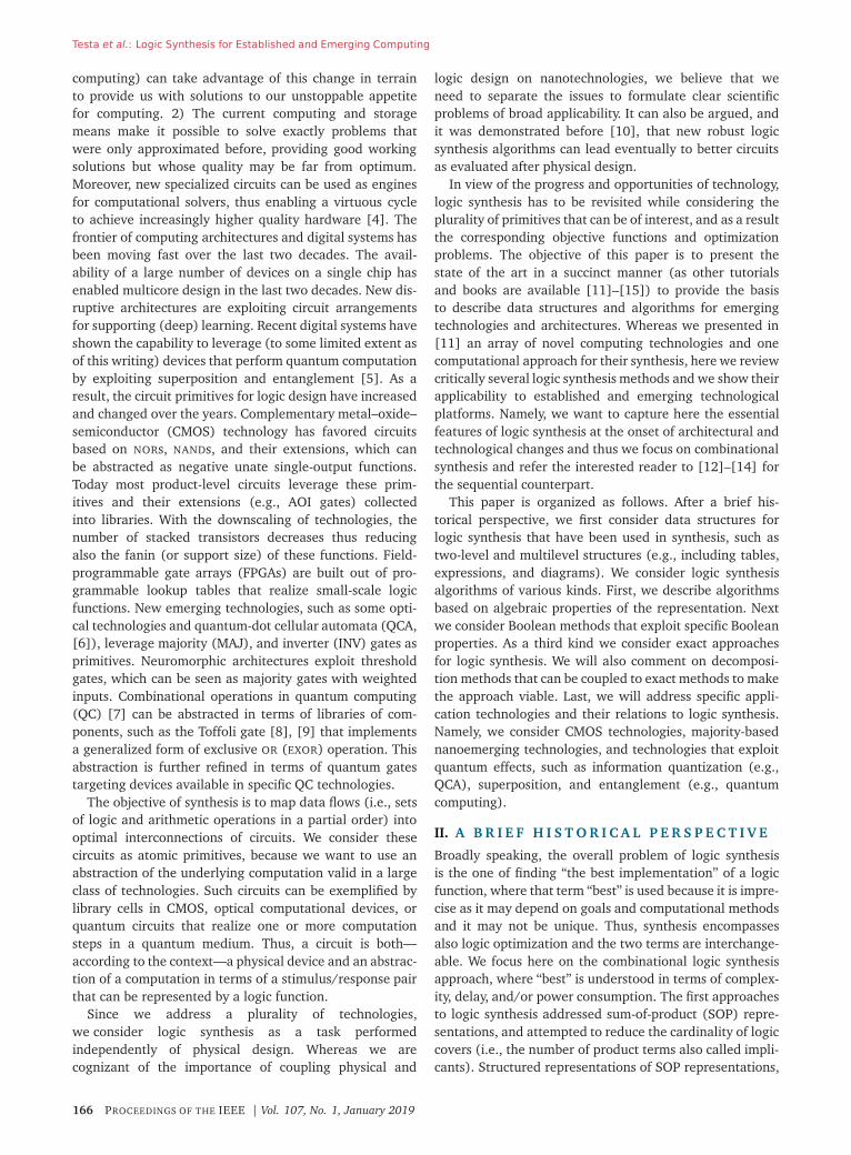
Fig. 1. BDD for the function (x� ⊕ x�x� ⊕ x�x� ⊕ x�) ∨∨∨ (x� ⊕ x�x� ⊕ x�x� ⊕ x�).
instead of “∨” in (1)]. Conjunctive normal forms playa central role in Boolean satisfiability solving (see, e.g.,[27] and [28]) and can be seen as the dual representationof disjunctive normal forms [29]. Exclusive sum-of-productrepresentations find extensive use in cryptography appli-cations (see, e.g., [30]–[32]) and quantum computing(see, e.g., [33] and [34]). Recently, also exclusive product-of-sum representations, which are the dual of exclusivesum-of-products, have been investigated in the context ofBoolean satisfiability of cryptography applications [35].
It is often feasible to represent Boolean functions intwo-level representations for 20–30 variables. Conjunc-tive normal forms are possible for functions with manyvariables, if one allows additional helper variables [36].Product terms for functions with up to 32 variables can berepresented in a computer using 64-b unsigned integers:the first 32 b are used to represent which variables occurin the product term, and the second 32 b are used torepresent whether the occurring literals are positive ornegative.
C. Binary Decision Diagrams
Logic functions can be expressed by decision diagrams inmany ways. The most common representation is the binarydecision diagram (BDD) [21], [37] which is a directedacyclic graph where internal nodes are associated withthe Shannon (also credited to Boole) expansion of thefunction, i.e., f = xifxi ⊕ xifxi , where fxi and fxi are thecofactors obtained from f when the variable xi is assigned1 or 0, respectively. When referring to BDDs, it is usuallyimplicitly understood that the variables are ordered andthe diagram reduced (i.e., BDD refers to ROBDDs [37]).Moreover BDDs are constructed and manipulated so thatredundancy is avoided, and thus they are canonical repre-sentation of logic functions.
Example 3: Fig. 1 shows the BDD for the function (x1 ⊕x2) ∨ (x3 ⊕ x4). Solid and dashed lines represent herepositive and negative cofactors, respectively.
BDDs exploit the fact that for many functions of prac-tical interest, smaller subfunctions occur repeatedly andneed to be represented only once. Combined with anefficient recursive algorithm that makes use of caching
168 PROCEEDINGS OF THE IEEE | Vol. 107, No. 1, January 2019
Testa et al.: Logic Synthesis for Established and Emerging Computing
techniques and hash tables to implement elementaryoperations, BDDs are a powerful data structure for Booleanfunction representation and manipulation. Indeed, algo-rithms for BDD manipulation have polynomial-time com-plexity (usually quadratic or cubic) in the number ofnodes, and such a number grows mildly with the prob-lem size (i.e., variables) in many—but not all—cases,e.g., multipliers.
The variable order in BDDs affects their size. Improvingthe variable ordering for BDDs (i.e., minimizing the BDDgraph size) is NP-complete [38]. An exact algorithm [39]and many heuristics [40] have been presented that aimat finding a good ordering. It is easy to fit a single BDDnode, which contains the variable index and pointers toits two children, into a single 64-b unsigned integer [21].Thus, BDDs can represent a good scalable representationfor logic functions. They can cope with larger functionsas compared to truth tables. When their storage becomesexcessive, functions are usually decomposed into blocksforming logic networks.
D. Multilevel Logic Networks
A multilevel logic network (LN) is interconnection ofblocks, each implementing a logic function and whoserepresentation style may vary. The interconnection is mod-eled by a directed acyclic graph where nodes representprimary inputs and outputs, as well as local functions. Inmost cases, such functions are restricted to have a singleoutput, by similarity to CMOS logic gates. For internalnodes, the indegree and outdegree are referred to as faninand fanout, respectively. Note that LNs can be extended todeal with sequential cyclic circuits [12], but such cases arenot considered here.
We use a formal notation for Boolean logic networksthat is also referred to as straightline programs or Booleanchains in the literature. Given primary inputs x1, . . ., xn, aBoolean logic network consisting of r local functions is asequence
xi = fi(xi1 , xi2 , . . ., xiar(fi)) for n < i ≤ n+ r (3)
where fi is a gate function with ar(fi) inputs and 0 ≤ ij < i
for 1 ≤ j ≤ ar(fi) are indexes to primary inputs orprevious gates in the sequence. For convenience, we definex0 = 0. Also, we define a sequence of primary outputsy1 = xo1 , . . ., ym = xom .
Example 4: A full adder with inputs x1, x2, x3 can berealized by the network
x4 = x1 ⊕ x2 ⊕ x3, x5 = 〈x1x2x3〉
with outputs y1 = x4 for the sum and y2 = x5 for the carry.The network uses the parity function f4 and the majorityfunction f5.
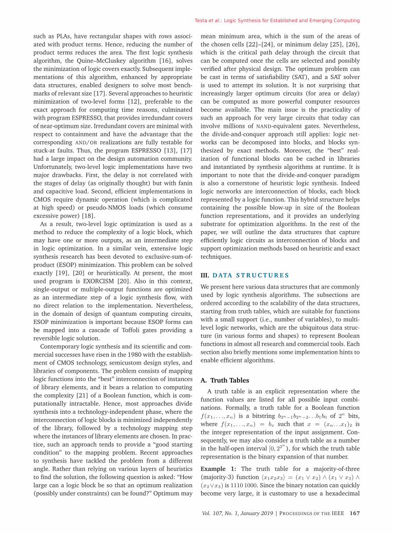
Logic networks can be specialized by placing restrictionson the internal nodes. A homogeneous LN is one wherethe fanin of each internal node is fixed. Restrictions canbe applied to local functions as well (e.g., networks con-sisting of NANDs and/or NORs). For example, AND-invertergraphs (AIGs), [41], [42] employ AND and inverters (orequivalently apply AND functions to positive/negative lit-erals). Majority-inverter graphs (MIGs), [43] use majorityand inverter gates and XOR-majority graphs (XMG) [44]use majority and EXOR gates. For FPGA design, boundedinput lookup tables k-LUT networks are used, wherear(f) ≤ k.
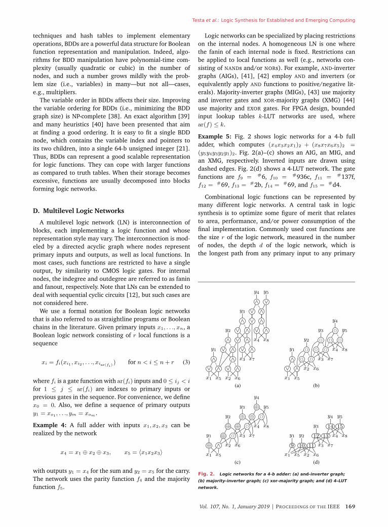
Example 5: Fig. 2 shows logic networks for a 4-b fulladder, which computes (x4x3x2x1)2 + (x8x7x6x5)2 =
(y5y4y3y2y1)2. Fig. 2(a)–(c) shows an AIG, an MIG, andan XMG, respectively. Inverted inputs are drawn usingdashed edges. Fig. 2(d) shows a 4-LUT network. The gatefunctions are f9 = #6, f10 = #936c, f11 = #137f,f12 = #69, f13 = #2b, f14 = #69, and f15 = #d4.
Combinational logic functions can be represented bymany different logic networks. A central task in logicsynthesis is to optimize some figure of merit that relatesto area, performance, and/or power consumption of thefinal implementation. Commonly used cost functions arethe size r of the logic network, measured in the numberof nodes, the depth d of the logic network, which isthe longest path from any primary input to any primary
Fig. 2. Logic networks for a 4-b adder: (a) and-inverter graph;
(b) majority-inverter graph; (c) xor-majority graph; and (d) 4–LUT
network.
Vol. 107, No. 1, January 2019 | PROCEEDINGS OF THE IEEE 169
Testa et al.: Logic Synthesis for Established and Emerging Computing
output, and the switching activity.1 Most synthesis methodsuse stepwise refinement, i.e., an iterated replacement offragments of the network while preserving input/output(I/O) behavior, mainly driven by heuristics descent strate-gies. Heuristics are chosen for the optimization goal (e.g.,area recovery subject to timing constraints) and select net-work nodes where logic transformations are likely to havea beneficial effect. Recently, exact methods have emergedas a means to achieve directly the optimum network for afunction, but its applicability is limited by the size of thenetwork. Heuristic and exact methods are reviewed next.
IV. A L G O R I T H M S
We present here the underlying techniques for logicoptimization algorithms. The minimization of two-levelSOPs can be achieved by the program ESPRESSO [17],which embodies both an efficient implementation of theQuine–McCluskey [16] algorithm for exact minimizationand fast near-optimum heuristics [13], [17]. The latteris used most often. The minimization of BDDs has beenaddressed by Drechsler [39] (exact method) and by othersthrough heuristics. Here, we concentrate on multilevelnetworks as this model is the most widespread, and wepresent heuristics first and exact methods later. It is inter-esting to remark that artificial intelligence methods (inparticular expert systems) were used in the early 1980s[45], [46] and later abandoned. A resurgent interest inmachine learning synthesis is noticeable at the time of thiswriting [47], [48], but the related results are not (yet)strong enough and broadly used to deserve a report.
Various approaches to LN optimization have historicalnames that we preserve here, namely algebraic methods(based on polynomial algebra), algebraic rewriting (basedon algebraic axioms, possibly of Boolean algebra), andBoolean methods (based on Boolean algebra). Heuris-tics are used in these approaches to select the type andsequence of transformations. While a combination of thesemethods (as often provided by the scripts of commercialtools) provide adequate engineering solutions, very fewproperties can be claimed on the synthesized circuits. Thishas motivated the recent search for exact methods that canyield subcircuits with provable properties.
A. Algebraic Methods
Traditional algebraic methods represent each LN nodein SOP form (minimal with respect to single-cube con-tainment [49]) and treat them as polynomials [49], [50].This simplifying abstraction enables fast manipulation ofvery large LNs. Algorithms are designed as operators thatiterate one type of transformation until the LN reaches alocal minimum (with respect to the transformation itself).
1We use abstract logic models to assess the quality of the networkbecause we present and compare various emerging technologies. Forestablished technologies, physical design and logic synthesis are com-bined, and optimality indicators are extracted from the circuit physicallayout.
Examples of transformations are extraction, substitution,decomposition, and algebraic rewriting [12], [49].
1) Extraction: Extraction consists of searching commonsubexpressions of two (or more) functions, expressed aspolynomials, in order to simplify the original ones. It relieson the search of appropriate common divisors (called ker-nels) that can be extracted to represent a new local func-tion; the associated variable can thus be used to simplifythe original expressions. The extraction problem can fur-ther be characterized as extraction of single-cube expres-sion (i.e., of a monomial), and of multiple-cube expres-sions (i.e., of a polynomial). The algorithm for computingkernels was proposed by Brayton and McMullen [49].
Example 6: Consider the logic network given by
yi = x1x3x5 + x2x3x5 + x4
yj = x3x4x5 + x2. (4)
The common expression yk = x3x5 can be extracted, andthe network can be reexpressed as
yi = yk(x1 + x2) + x4
yj = ykx4 + x2
yk = x3x5. (5)
2) Substitution: Substitution (also called resubstitution)means simplifying a local function by using an additionalinput coming from a node already present in the network.This input realizes already a part of the function that thusneeds not to be replicated. Algebraic substitution makesuse of algebraic division [49]: an expression yi can beexpressed as yjyquotient + yremainder, where yj is a divisorof the original function yi.
Example 7: Consider the logic network given by
yi = x1x3 + x1x4 + x2x3 + x2x4 + x5
yj = x1 + x2. (6)
Function yj is a divisor of yi and can therefore be used toexpress the network as
yi = yj(x3 + x4) + x5
yj = x1 + x2. (7)
The implementation of algebraic substitution algorithms[49] can be very fast and provide an efficient algorithm forlogic optimization.
3) Decomposition: Decomposition splits a local func-tion (that may be too complex) into two smaller ones.The reverse transformation, i.e., merging to local func-tions is called elimination. There are many ways to per-
170 PROCEEDINGS OF THE IEEE | Vol. 107, No. 1, January 2019
Testa et al.: Logic Synthesis for Established and Emerging Computing
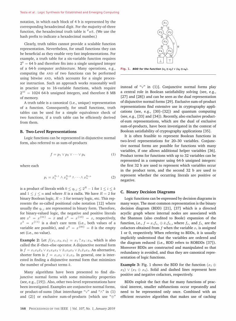
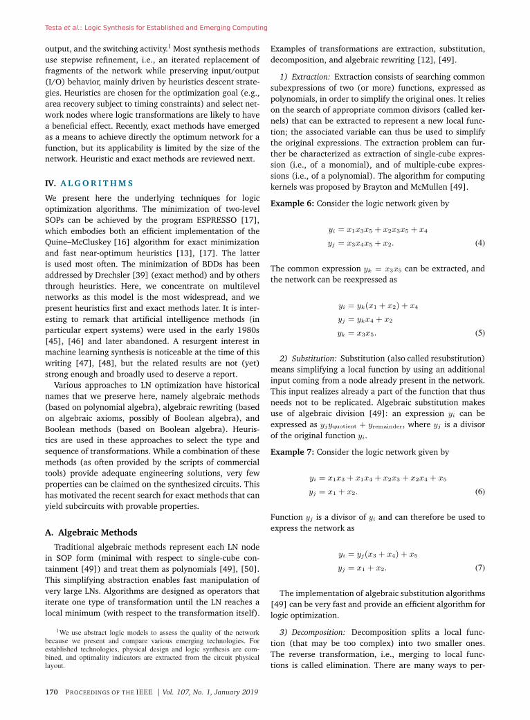
Fig. 3. Example of AIG rewriting from [52]. (a) Functionally
equivalent AIG structures. (b) Rewrite structure A into B. (c) Rewrite
structure B into A.
form decomposition of logic functions [12], [50], [51].A straightforward way is to divide algebraically a functionyi by one of its kernels that becomes a new node in theLN associated with variable j. Thus, yi can be expressed asjyquotient + yremainder. In contrast to substitution, decom-position associates a new variable with the divisor. Decom-position can be applied recursively on the quotient andremainder.
Example 8: Consider the expression
yi = x1x2x5 + x2x3x5 + x4. (8)
Let us introduce a new variable j = x1x2 +x2x3; it followsyi can be decomposed as
yi = jyquotient + yremainder = jx5 + x4. (9)
4) Algebraic Rewriting: The purpose of algebraic rewrit-ing is to reshape portions of an LN in order to improvethe number of nodes and levels [52]. The general ideaconsists of applying transformation rules (based on alge-braic axioms) with the objectives of improving some fig-ure of merit. Rewriting is more effective when LNs arehomogeneous (e.g., AIGs, MIGs, and XMGs), because logictransformations can be made specific. Algebraic rewritinghas been used extensively in ABC [52]. For example, onecan hold a database of precomputed circuit structuresfor a function. For any subcircuit, one can compute itsfunction and check whether replacing the subcircuit by aprecomputed structure leads to an improvement. If othernodes in the circuit are reused in the rewriting, it may beeven beneficial to replace a smaller structure by a largerone.
Example 9: An example for AIG rewriting as it is imple-mented in ABC is shown in Fig. 3. Fig. 3(a) showsthree functionally equivalent AIGs structures. These equiv-alences are employed in Fig. 3(b) and (c) to reshape thestructure of AIGs into functionally equivalent ones.
Refactoring is a variant of rewriting, in which largecones of logic feeding a node are iteratively selectedwith the aim to replace them by a factored form of thefunction. The change is accepted if there is an improve-ment in the selected cost metric (usually the number ofnodes) [52], [53].
Algebraic rewriting is very effective for MIGs and XMGs.The related majority algebra and axiomatic system Ω havebeen described in [43], where it is shown that Ω is soundand complete, providing reachability in the solution space.In simple words, this means that for MIGs and XMGs thereexist a sequence of steps leading to the optimum solution.Such a path may not exist in other representation frame-works. Indeed, experimental evidence has shown that theMIGhty program [43] implementing algebraic rewritinghas outperformed other tools on several benchmarks [43],and especially on large arithmetic functions.
The MIG axiomatic system Ω consists of five primitivetransformation rules that can be used to rewrite MIGs
Ω
�������������������������������������������
Commutativity−Ω.C
〈xyz〉 = 〈yxz〉 = 〈zyx〉Majority−Ω.M
〈xxy〉 = x 〈xxy〉 = y
Associativity−Ω.A
〈xu〈yuz〉〉 = 〈zu〈yux〉〉Distributivity−Ω.D
〈xy〈uvz〉〉 = 〈〈xyu〉〈xyv〉z〉Inverter Propagation−Ω.I
〈xyz〉 = 〈xyz〉.
(10)
An MIG can be transformed into another MIG byjust using the rules in Ω in either direction as well asadditional rules. Such rules can reduce the number ofnodes and depth of an LN, or any other metric [10].Note that MIGs can be generalized to using majority-nfunctions [54], [55].
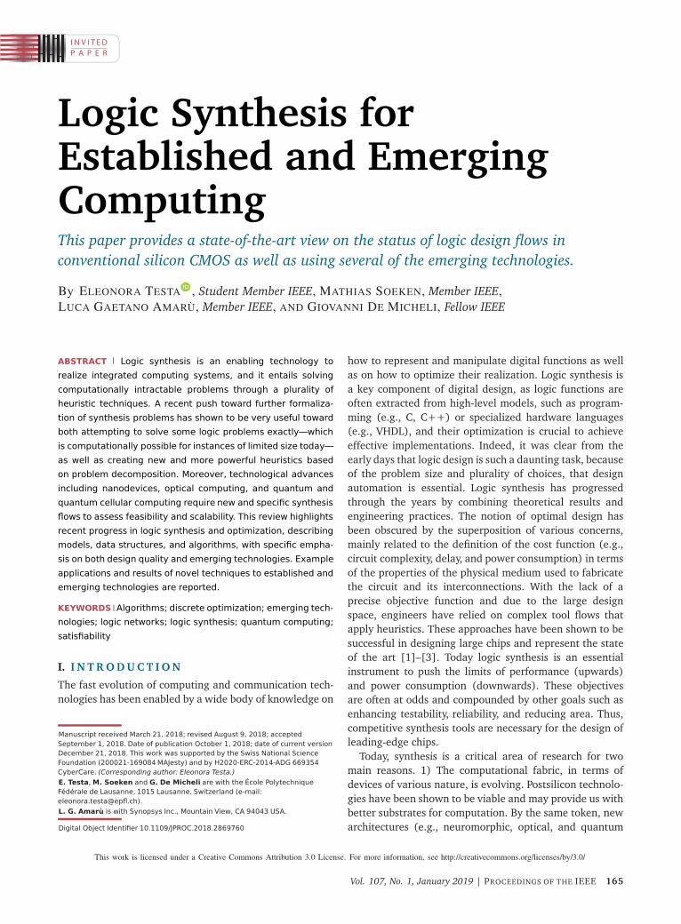
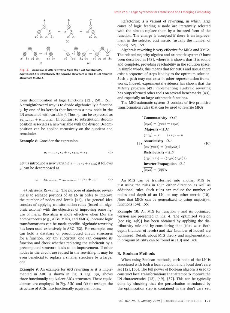
Example 10: An MIG for function y and its optimizedversion are presented in Fig. 4. The optimized version[see Fig. 4(b)] has been obtained by applying the dis-tributivity rule and by considering that 〈10x〉 = x. Bothdepth (number of levels) and size (number of nodes) areoptimized. Details about MIG theory and implementationin program MIGhty can be found in [10] and [43].
B. Boolean Methods
When using Boolean methods, each node of the LN isassociated with both a local function and a local don’t careset [12], [56]. The full power of Boolean algebra is used toconstruct local transformations that attempt to improve theLN characteristics [12], [49], [57]. This can be typicallydone by checking that the perturbation introduced bythe optimization step is contained in the don’t care set,
Vol. 107, No. 1, January 2019 | PROCEEDINGS OF THE IEEE 171
Testa et al.: Logic Synthesis for Established and Emerging Computing
Fig. 4. MIG algebraic rewriting. (a) MIG: before algebraic
rewriting. (b) MIG: after rewriting.
which represents the tolerance on the perturbation. In thisscenario, often the function at a node n can be changedto another function without affecting the functionality atthe primary outputs [58], [59]. The new function wascalled a permissible function for node n by Muroga, whodid pioneering work on these methods [59]. Unfortunately,his work based on tabular descriptions had limited impactbecause the data structure and algorithms, as well as thecontemporary computers, were not efficient enough tooperate on LN of reasonable size.
Boolean methods evolved through time as differentengines became available for doing the essential taskof detecting the existence of permissible functions. TheMIS/SIS program [50] used program ESPRESSO to findpermissible functions by optimizing the literal count oftwo-level logic expressions associated with LN nodesand their don’t care sets. This approach is fast andpractical, but not general enough as it may miss goodsolutions.
Other tools used BDDs to check if a function is apermissible replacement of another by checking the tau-tology of their equivalence. Fast tautology check can beprovided by BDD tools [60] and thus desirable permissiblereplacements of a local function can be quickly evaluated.As a specific example, technology mapping with Booleanmatching aims at replacing a portion of an LN by anelement of a cell library. The feasibility of the match-ing is done using BDDs [61], [62]. Moreover, when thecandidate permissible functions are many, their implicitenumeration through BDDs [62] makes their search veryeffective.
In general, Boolean methods can also be enabled bycasting the search for permissible functions as a satisfia-bility problem, and using an effective SAT solver for thistask [63]. Overall, Boolean methods leverage a varietyof transformations that eventually resort to an engine forverifying their applicability. Examples of engines are two-level minimizers, BDD, and SAT packages. We review sometransformations next.
1) Substitution: As in the algebraic methods, substitu-tion reexpresses the local function of an existing nodeusing the input of other nodes already present in theLN. Substitution can be computed in various ways and it
is inherently more expensive than algebraic substitution.Traditionally, it is realized by minimizing a local functionwith its local don’t care set, which may contain variablesnot originally present in the function support. Indeed thelocal don’t care set expresses the mutual controllability andobservability links among local functions in an LN, andthus enables the reexpression of a portion of a functionthrough a new input.
Example 11: Consider the logic network given by
y1 = x1 + x2x3x4 + x5
y2 = x1 + x3x4. (11)
Assume that we want to substitute y2 into y1. Then, weminimize y1 with the don’t care conditions induced bythe second assignment y2 ⊕ (x1 + x3x4). The minimizedexpression yields
y1∗ = x1 + x2y2 + x5
y2 = x1 + x3x4 (12)
thus effectively reducing one literal in the first expressionby using the output of the second one.
2) Rewriting: Rewriting aims at minimizing the sizeof an LN by iteratively selecting subnetworks and byreplacing them with smaller precomputed subgraphs,while preserving the functionality. This is achieved byapplying a Boolean equivalence check (modulo thedon’t cares).
Example 12: Examples of typical precomputed subnet-works are all four variables functions, or their 222 NPNequivalence classes [23], [44], [52]. Here, the idea is toreplace four-input subnetworks with their optimum pre-computed representation.
3) Redundancy Removal and Rewiring: Redundancyremoval is a common technique that uses automatic testpattern generators (ATPGs) to detect untestable stuck-atfaults in an LN and modifies the network at the faultynet by setting it to a constant value [64], [65]. Rewiringimproves on redundancy removal because it adds newconnections in an LN to create redundancies that later canbe removed. In practice, it adds and removes nets and itaims at removing nets related to long wires [66].
Rewiring fits into a general paradigm where an LN isoptimized by changing a local function (to improve overallsize and/or depth) by introducing errors that are thencorrected by changing the local functionality somewhereelse [67]. The following example shows this type of trans-formation for MIGs.
Example 13: We show an example that makes use of aninduced error correction technique for MIGs, which wasfirst explained in [68]. The technique is based on the
172 PROCEEDINGS OF THE IEEE | Vol. 107, No. 1, January 2019
Testa et al.: Logic Synthesis for Established and Emerging Computing
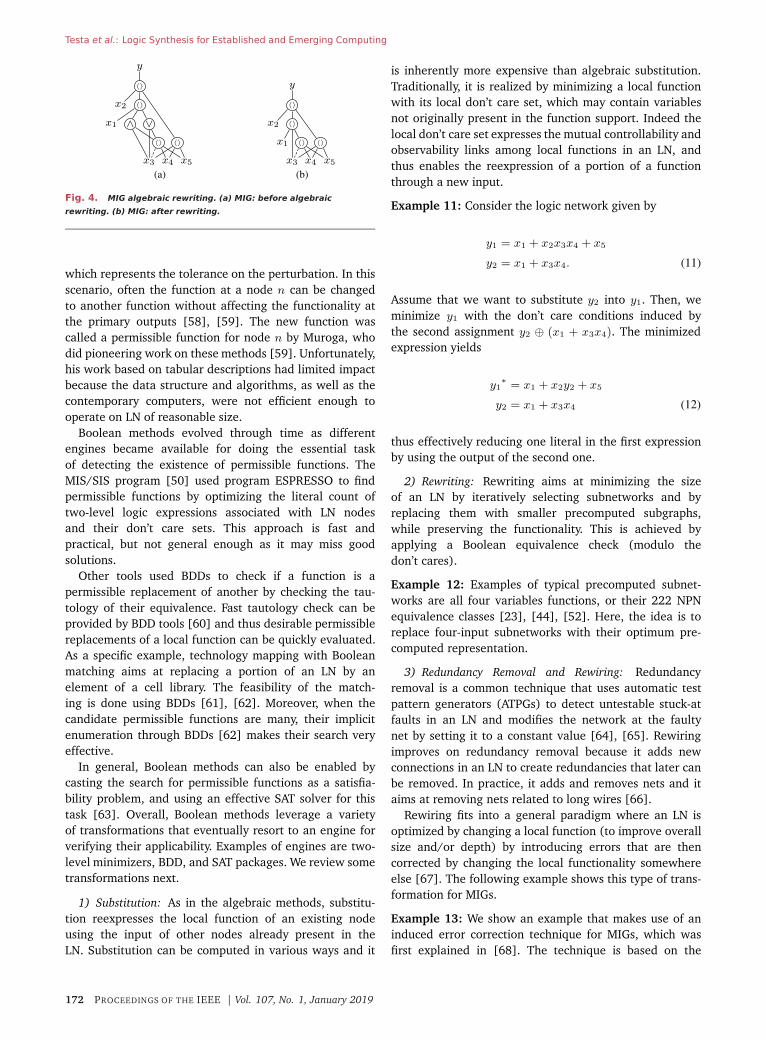
Fig. 5. Rewiring based on induced error correction in MIGs.
(a) Initial MIG. (b) Optimized MIG.
property that
y = 〈y1y2y3〉 if, and only if
(y ⊕ yi)(y ⊕ yj) = 0 for all 1 ≤ i < j ≤ 3.
(13)
We can think of each yi, i = 1, 2, 3 as a convenient(i.e., reduced and thus incorrect) version of y. The dif-ference between yi and y is expressed by (y ⊕ yi) in thelocal error. The condition on the right-hand side of (13)states that all three errors must be pairwise orthogonal,i.e., the pairwise differences have an empty intersection.In this condition, the majority operator restores the correctfunctionality. Fig. 5(a) shows an MIG for the function y,which has the truth table #f8f8f8e0f8e0e0e0. One caneasily verify that the right-hand side condition in (13) issatisfied for y1 = 〈x1x2x3〉, y2 = x3, and y3 = 〈x4x5x6〉,and therefore, y = 〈〈x1x2x3〉x3〈x4x5x6〉〉, for which anMIG is shown in Fig. 5(b). The optimized MIG reduces bothsize and depth to half of their original values. More detailson this technique including methods to derive valid faultcandidates are described in [68].
C. Exact Methods
Exact synthesis is the problem of finding the optimumlogic representation for a given Boolean function withrespect to some cost criterion. We consider here logicnetworks where the cost is either the number of gates (orequivalently nodes and correlated to area) or the depthof the LN (or equivalently the critical path and correlatedto delay). For example, a well-known exact algorithm isFlowMap that determines a minimum-depth mapping ofan LN into k-LUTs in polynomial time [69]. Note that anoptimum circuit implementation is not necessarily unique.For example, the majority-5 function can be realized withthe minimum number of majority-3 gates in more than oneway, for example
〈〈x3x4x5〉x2〈x1x2〈x3x4x5〉〉〉
and〈x1x2〈〈x3x4x5〉x2〈x3x4x5〉〉〉.
Theoretical bounds can be derived under variousassumption. For example all four-variable Boolean func-tions can be represented using SOPs with at mosteight implicants [19]. All five-variable Boolean functionscan be represented using two-input LNs with at most12 gates [21]. Since the number of Boolean functionsgrows double exponentially with the support size, it ishard to compute bounds for a larger number of variables.To give a sense of the kind and applicability of exactsynthesis, we present here two exact synthesis methods:1) an implicit LN enumeration method for area minimiza-tion; and 2) an explicit LN enumeration method for delayminimization. We refer the interested reader to [70] fordetails and other approaches.
1) Implicit Network Enumeration Methods: Implicit net-work enumeration methods aim at exploring the logicrepresentation space, in search for optimum networks,with the help of constraint satisfaction and optimiza-tion techniques, such as integer linear programming orBoolean satisfiability [71]. Implicit enumeration methodsare considered the most scalable ones for exact synthesis,especially considering Boolean functions of five, six, ormore variables, implemented in common technologies. Inthis work, we focus on Boolean satisfiability as a mainreasoning engine for exact synthesis.
To showcase how implicit enumeration methods forexact synthesis can be driven by SAT engines, we presentin the following details on “SAT-based exact synthesis forminimum gate count.” The same approach can be naturallyextended to minimum delay, minimum power, and othertypes of network costs, hence it will not be discussed herefor the sake of brevity.
a) SAT-based exact synthesis: Given an m-tuple of mfunctions over n variables
(y1(x1, . . ., xn), . . ., ym(x1, . . ., xn))
we can formulate the exact synthesis of these functions asa sequence of decision problems P0, P1, P2, . . .. ProblemPr corresponds to the question: Can functions y1, . . ., ym
be computed by an r-gates Boolean LN? Without loss ofgenerality, we assume as a default situation that any two-input logic gate is available for synthesis, but the problemformulation can be tailored to a given technology librarythat implements a universal gate set. Each instance Pr canbe described by a SAT formula.2 Hereafter, we describewhat such a formula looks like, how additional constraintscan speed up the synthesis process, as well as some experi-mental results. We attribute the SAT formulation describedhere to Kojevnikov et al., [22], Knuth [28], and Eén[71].Knuth [28] improved previous approaches, by restrictingsynthesis to normal Boolean functions.
2In practice, P0 is often handled as a trivial special case, since itmeans that all y1, . . .ym are constants or variable projections.
Vol. 107, No. 1, January 2019 | PROCEEDINGS OF THE IEEE 173
Testa et al.: Logic Synthesis for Established and Emerging Computing
b) Definitions and variables: For our SAT-based exactsynthesis purposes, an r-gates LN with n inputs x1, . . ., xn
is a sequence of (two-input) gates (xn+1, . . ., xn+r)
with
xi = xj(i) ◦i xk(i), for n+ 1 ≤ i ≤ n+ r. (14)
That is, each gate combines two previous gates or inputswith j(i) < k(i) < i using ◦i, which is one of the two-input Boolean functions. For single-output functions, thelast gate xn+r is considered the network’s output. Formultiple-output networks, each gate could potentially bean output. We call a single-output function f normal, iff(0, . . ., 0) = 0. A multiple-output function is normal, ifall of its component functions are normal. An LN rep-resents normal functions if all of its gate functions arenormal.
To proceed with the formulation of this exact synthesisproblem, we define the variables to be used in the SATformula. For 1 ≤ h ≤ m, n < i ≤ n + r, and 0 < t < 2n,define the following:
xit : tthbit ofxi′struthtable
gih : [yh = xi]
sijk : [xi = xj ◦i xk]for 1 ≤ j < k < i
fipq : ◦i(p, q)for 0 ≤ p, q ≤ 1, p+ q > 0.
The variables xit correspond to the value (at row t) of theglobal truth table for gate xi. The gih variables determinewhich outputs point to which gates. Thus, if gih is true,it means that function yh is computed by gate i. Thesijk variables determine, for each gate i, the inputs j
and k. Also known as selection variables, their assignmentscontrol the underlying DAG structure of the LN. The fipq
encode for all gates i what the corresponding Booleanoperator is. Since we synthesize normal logic networks,we do not need to consider row 0 of the gate’s truthtables and require only 2n − 1 truth table indices t. Alsop + q > 0, since the local function describing a gate’soperation does not need to be specified for the casep = q = 0.
c) Constraints: We now constrain the variables by aset of clauses which ensure that the network computesthe correct functions. With the addition of these clauses,the SAT formula is satisfiable if and only if the givenfunctions can be computed by an r-gate logic network. For0 ≤ a, b, c ≤ 1 and 1 ≤ j < k < i, the main clausesare
((sijk ∧ (xit ⊕ a) ∧ (xjt ⊕ b) ∧ (xkt ⊕ c)) → (fibc ⊕ a)).
In other words, if gate i has inputs j and k, and the tth bitof xi is a, and the tth bit of xj is b, and the tth bit of xk
is c, then we must have ◦i(b, c) = a. We can rewrite these
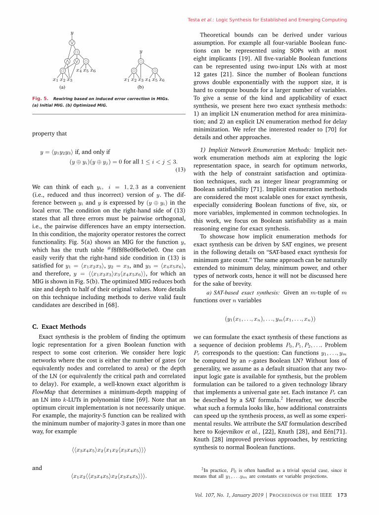
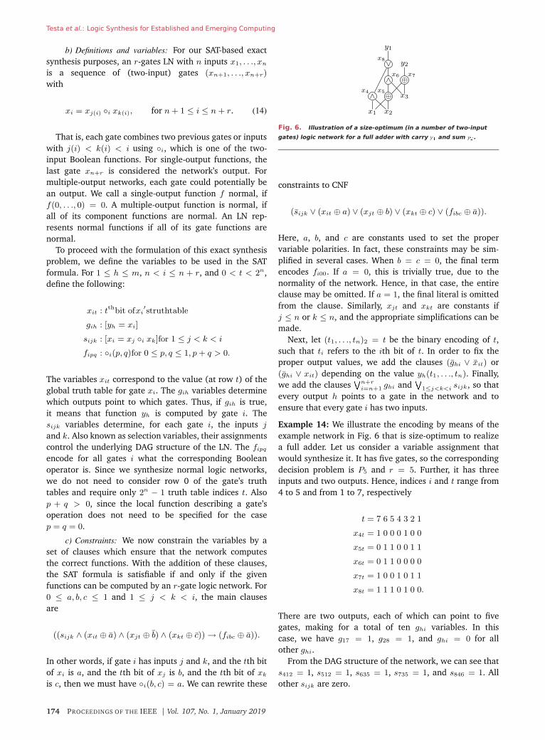
Fig. 6. Illustration of a size-optimum (in a number of two-input
gates) logic network for a full adder with carry y� and sum y�.
constraints to CNF
(sijk ∨ (xit ⊕ a) ∨ (xjt ⊕ b) ∨ (xkt ⊕ c) ∨ (fibc ⊕ a)).
Here, a, b, and c are constants used to set the propervariable polarities. In fact, these constraints may be sim-plified in several cases. When b = c = 0, the final termencodes fi00. If a = 0, this is trivially true, due to thenormality of the network. Hence, in that case, the entireclause may be omitted. If a = 1, the final literal is omittedfrom the clause. Similarly, xjt and xkt are constants ifj ≤ n or k ≤ n, and the appropriate simplifications can bemade.
Next, let (t1, . . ., tn)2 = t be the binary encoding of t,such that ti refers to the ith bit of t. In order to fix theproper output values, we add the clauses (ghi ∨ xit) or(ghi ∨ xit) depending on the value yh(t1, . . ., tn). Finally,we add the clauses
�n+ri=n+1 ghi and
�1≤j<k<i sijk, so that
every output h points to a gate in the network and toensure that every gate i has two inputs.
Example 14: We illustrate the encoding by means of theexample network in Fig. 6 that is size-optimum to realizea full adder. Let us consider a variable assignment thatwould synthesize it. It has five gates, so the correspondingdecision problem is P5 and r = 5. Further, it has threeinputs and two outputs. Hence, indices i and t range from4 to 5 and from 1 to 7, respectively
t = 7 6 5 4 3 2 1
x4t = 1 0 0 0 1 0 0
x5t = 0 1 1 0 0 1 1
x6t = 0 1 1 0 0 0 0
x7t = 1 0 0 1 0 1 1
x8t = 1 1 1 0 1 0 0.
There are two outputs, each of which can point to fivegates, making for a total of ten ghi variables. In thiscase, we have g17 = 1, g28 = 1, and ghi = 0 for allother ghi.
From the DAG structure of the network, we can see thats412 = 1, s512 = 1, s635 = 1, s735 = 1, and s846 = 1. Allother sijk are zero.
174 PROCEEDINGS OF THE IEEE | Vol. 107, No. 1, January 2019
Testa et al.: Logic Synthesis for Established and Emerging Computing
Table 1 Exact Area Synthesis of all Four and Five-Input NPN Classes and
a Set of Six-Input DSD Functions. All Runtimes Are in Milliseconds
Finally, the Boolean operators for the different gates areassigned the following values:
(p, q) = (1, 1) (0, 1) (1, 0)
f4pq = 1 0 0
f5pq = 0 1 1
f6pq = 1 0 0
f7pq = 0 1 1
f8pq = 1 1 1.
d) Additional clauses: The above clauses are the min-imum ones necessary to ensure that a valid logic networkis found. However, we may add additional constraints toboost synthesis speed, such as clauses to force a colexico-graphic order on the gates. We refer the reader to [28] forthe details.
e) Algorithms: Now that we know how to create theSAT formula for Pr, we can use that to construct an exactsynthesis algorithm. We would start by solving SAT(Pi),with i = 0, and then increasing i as long as the answeris unSAT. It is evident that the first satisfiable answercorresponds to an exact circuit solution.
f) Experimental results: Table 1 shows experimentalresults for the synthesis of three sets of functions, usingthe algorithm described in this section. The set NPN4consists of all 222 four-input NPN classes. The set NPN5consists of all 616 126 five-input NPN classes. The setFDSD6 consists of 1000 fully disjoint support set (DSD)decomposable functions [72]. NPN4 and FDSD6 sets offunctions can be fully synthesized in less than 70 s. Onaverage, all functions are synthesized in (much) less than1 s. Interestingly, the six-input DSD functions have a loweraverage runtime than the four-input NPN classes. This isdue to the fact DSD functions are rather special functions,at times easier to synthesize. Considering NPN5, not onlythe number of classes is about 3000× larger than NPN4,but also the average complexity of each function increases.As a result, exact synthesis of each five-variable function ismore difficult than in the four-variable case.
2) Explicit Network Enumeration Methods: Explicit enu-meration methods aim at exhaustively exploring the logicrepresentation space, or a well-defined subportion, lookingfor optimum networks. For Boolean functions with four,five variables maximum, or considering exact synthesisproblems with special constraints on network topology,a small number of gates, etc., explicit enumeration canoutperform implicit enumeration in terms of executionruntime. For example, it takes less than 2 min to generate
all delay-optimal circuits of four variables, for more than200 input arrival time patterns, using a recently introducedexplicit enumeration method [25]. On the other hand,SAT-based methods can take more than 3 h to find thesame circuits. However, one has to be cautious whenusing explicit network enumeration: when the number ofvariables grows too much, or the filters on the search spaceare not tight enough, explicit network enumeration maybe inapplicable because of the memory footprint, withouteven considering the super-exponential runtime blowup.Nevertheless, there are still applications in EDA whereexplicit enumeration is of interest [73].
To showcase how explicit enumeration methods forexact synthesis can be implemented effectively, we presentin the following a procedure for optimum delay circuitsenumeration. The same approach can be extended to theminimum area and other metrics: we refer the readerto [25] for more details.
a) Optimum delay circuits enumeration: We considerthe problem of finding all minimum delay logic circuitsof n variables, given a technology library L and inputarrival pattern T . This problem arises when a completeexact delay database needs to be populated [25]. Thefollowing procedure that we are going to describe depictsa high-level flow for explicit circuit enumeration for exactdelay synthesis. We first store trivial circuits for the logicconstants and input variables. These circuits, which aresimple wires, are delay optimal by construction. Then, westart an enumeration loop where we try to add a new gatefrom L, in increasing delay order, having as fanin someof the already stored functions, also in increasing arrivaltime order. If the generated function is not already stored,we save it. Otherwise, we already have a better delayimplementation stored for the generated function. We keepiterating this procedure until we have stored circuits forall the 22n
functions. It can be proven that this proce-dure only stores optimum delay circuits. Note that suchprocedure can be sped up by taking into account libraryconsiderations and function filtering. On the library side,we can filter based on the gate properties, e.g., functionalsymmetry, delay dominance and decomposition, etc. Onthe function side, we can filter based on considerations onNPN classification properties of the already stored func-tions. With all the filtering, explicit enumeration is fast. Ittakes less than 2 min to generate all optimum delay circuitsof four variables for a typical L in CMOS technology [25].
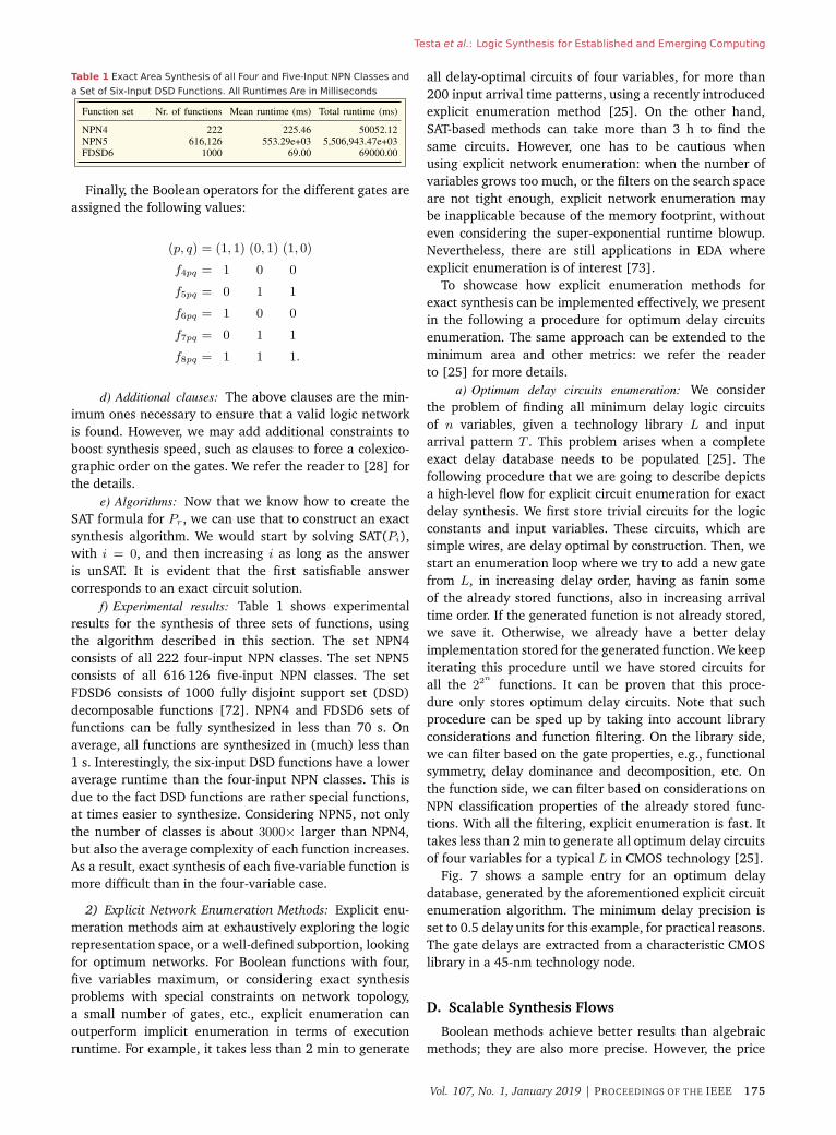
Fig. 7 shows a sample entry for an optimum delaydatabase, generated by the aforementioned explicit circuitenumeration algorithm. The minimum delay precision isset to 0.5 delay units for this example, for practical reasons.The gate delays are extracted from a characteristic CMOSlibrary in a 45-nm technology node.
D. Scalable Synthesis Flows
Boolean methods achieve better results than algebraicmethods; they are also more precise. However, the price
Vol. 107, No. 1, January 2019 | PROCEEDINGS OF THE IEEE 175
Testa et al.: Logic Synthesis for Established and Emerging Computing
Fig. 7. Sample entry of an optimum delay circuit database.
for better quality is worse scalability. Exact methods canfind optimum circuits and are applicable when circuitsare sought in the presence of many constraints; but thesemethods are only applicable to functions with a few num-ber of inputs. This section discusses how such techniquescan nevertheless be integrated into a robust and scalablesynthesis flow, by making use of partitioning techniques.Breaking down the logic network into smaller fractionsallows us to apply runtime-intensive methods in a control-lable manner.
1) Windowing: A generic scalable logic synthesis frame-work is described by Mishchenko and Brayton [53]. Thegeneral idea is to move a small window (with restrictedand controllable fanin and unlimited fanout) over thelogic network. Algorithms can be applied on the windowresulting in local optimization of subgraphs. Generally, awindowing procedure takes as input a directed acyclicgraph and two positive integers which denote the maximalnumber of primary inputs of the window and the maximalnumber of nodes, respectively. We refer the reader to [53]for a detailed description of the algorithm.
2) LUT Mapping: LUT mapping allows us to cover thelogic network with k-input lookup tables. LUT mappingis usually based on k-feasible cut enumeration [74]–[76],and depth-optimal LUT mapping is based on the FlowMapalgorithm [69]. k-LUT mapping can be used as partitionmethod of large networks in order to apply exact solutionson smaller functions of k inputs. Results of exact synthesisalgorithm on LUT-mapped networks can be found in [44]to optimize size and in [26] to optimize logic depth.
V. A P P L I C AT I O N S
Logic synthesis is a technology enabler [11], in the sensethat it allows us to validate the effectiveness of new tech-nologies on established and emerging architectures. Somesystem and technology trends are reviewed in this specialissue. It can be argued that future computing systems willinvolve a plurality of hardware solutions, in the search ofthe best match to the application of interest.
Whereas the results of using logic synthesis in vari-ous emerging technologies has been reported elsewhere[77]–[79] and reviewed in [11], we consider here theapplications of logic synthesis methods to CMOS technol-ogy, optical computing (focusing on plasmonic logic), andquantum-dot cellular automata as well as quantum com-puting. This choice is motivated by the belief that CMOS
will continue to be the mainstream technology, enhancedby emerging optical computing and communication tech-nology. Similarly, we think that a design flow includingspecialized logic synthesis is necessary to scale up quantumcomputing (in various technologies and embodiments)to provide us with versatile and powerful computingmeans.
A. CMOS Targeted Synthesis
This section demonstrates applications for classicalCMOS technologies in which the novel logic synthe-sis data structures and algorithms described in thispaper lead to significant improvements. First, we showhow majority-based logic networks as intermediate rep-resentation enable further logic optimization that car-ries through to technology mapping. Second, we showexamples in which SAT-based techniques are successfullyemployed into scalable synthesis flows for standard celland LUT-mapping.
The most recent results obtained using majority-based(i.e., MIGhty) logic optimization are reported in [10].Logic functions are represented by MIGs and further opti-mized using both algebraic and Boolean methods, heresummarized in Section IV. A selection of circuits fromboth IWLS’05 benchmarks and HDL arithmetic bench-marks have been considered and synthesis results obtainedwith MIGhty are compared to AIGs optimized by ABC[80] in terms of size and depth. Considering the IWLS’05benchmarks, an average 14% reduction in depth and 4%in size are achieved by MIGhty. Focusing on the arithmeticHDL benchmarks, MIGhty enables about 33% depth reduc-tion combined with 4% reduction in size. Note that theseimprovements are obtained with similar runtime betweenMIGhty and ABC. The benefits in area and delay are alsofound after place and route, although part of the advantageis absorbed by place and route. For the case of FPGA design(synthesis followed by place and route) on a commercial28-nm technology node, employing MIGhty as front-end tothe FPGA design flow, better final circuits are obtained bothin terms of LUT count, delay, and power metrics. Whentargeting delay as main optimization objective, a 10%improvement is achieved [10, Table 3]. The application-specific integrated circuit (ASIC) design follows a similartrend on a commercial 22-nm technology node. MIGhtyachieves better final circuits both for area, delay andpower. Also in this case, when targeting delay as mainoptimization objective, a 13% improvement is obtained[10, Table 4].
The first SAT-based framework dealing with standardcells has been recently included in ABC [53] and reportedin [81]. A novel SAT-based procedure is used to enumeratestandard-cell implementations of the target node. It isemployed as a postprocessing step, aiming at reducingthe size of already mapped networks. The experimentalresults show that a 2.5% further reduction [81, Table 1]in the number of standard cells is obtained when opti-mizing circuits mapped using heuristics from ABC. A most
176 PROCEEDINGS OF THE IEEE | Vol. 107, No. 1, January 2019
Testa et al.: Logic Synthesis for Established and Emerging Computing
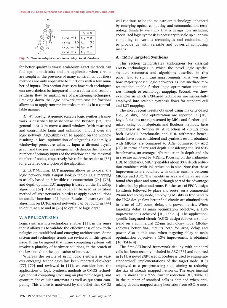
Fig. 8. (a) Layout for a plasmonic-based majority-3, and (b)
three-stage cascaded plasmonic majority circuit.
recent work has considered SAT-based area recovery fortechnology mapping [82]. The SAT-based procedure hasbeen implemented in ABC and tested on a suite of EPFLbenchmarks [68] mapped into 6-LUT logic network. Whentargeting area reduction, an average area reduction of3.5% is obtained and a delay improvement is achievedin most examples. For several arithmetic benchmarks, thearea reduction is very substantial, with values up to 11%[82, Table 2].
Open source implementations of most of aforemen-tioned synthesis algorithms for CMOS are available atgithub.com/lsils/mockturtle.
B. Majority-Based Technologies
With transistor dimensions reaching their scaling lim-its, it is interesting to look at disruptive computationparadigms offered by emerging nanotechnologies. Exam-ples of majority-based beyond CMOS technologies include,but are not limited to, quantum-dot cellular automata(QCA, [6]), nanomagnet logic [83], spin-based devices(e.g., spin-wave devices [84] and spin torque majoritygates [85]), and plasmonic-based devices [86]. Here, wedescribe as examples plasmonic-based devices and QCA,and we illustrate how logic synthesis data structures andalgorithms described so far can be employed in order torealize logic circuits based on these new paradigms ofcomputation. It is worth noting that logic synthesis forspin-based devices has already been extensively studied[11], [77]; nevertheless, the following discussion can beeasily extended and applied to other majority-based nan-otechnologies.
1) Plasmonic-Based Devices: Plasmonic-based devices[86] described hereafter are based on the propagation ofsurface plasmon polaritons (SPP, [87]), which are electro-magnetic waves propagating at the interface between adielectric and a metal. In particular, plasmonic-based logicmakes use of the phase φ of the SPP as logic variable.The computation is based on the interference of waves: ingeneral, the output depends on the number of inputs withphase φ and φ+ π.
Functionality: The phase of interfering SPP waves fol-lows the majority rule; this makes the three-input majorityfunction easy to realize with plasmonic-based devices [86].Fig. 8(a) shows a single-stage three-input plasmonicmajority gate layout.
Thanks to the physics of plasmonic devices that canbe abstracted as multivalued logic, it has been shown[86] that a nine-input majority gate can be easily realizedusing four three-input plasmonic devices. Note that thebest realization of majority-9 in binary-valued logic knownso far uses 15 majority-3 gates [55], and thus plasmonicdevices may be more efficient (as compared to other wave-based devices) to realize logic circuits. The wave natureof the computation allows us to easily implement theINVerter by using a waveguide of half the length of the SPPwavelength. Thanks to this property, a complete set of logicprimitives (INV and MAJ) can be build using plasmonic-based devices.
a) Constraints and costs: As stated above, plasmonic-based devices make a complete set of Boolean primitives;however, some constraints arise due to the wave natureand the physics of this device. As an example, the prop-agation losses of SPP puts a limitation on the number ofcascaded stages (i.e., the number of levels of the circuits).Currently, it is not efficient to have more than three stages,which means that after the third stage, either an amplifieror a converter to voltage domain is necessary. An exampleof three-stage cascaded plasmonic majority is shown inFig. 8(b). The propagation losses across the first stageare around 30%, and keep increasing at every cascadedstage. The increase in propagation losses between thedifferent stages is a direct consequence of the size differ-ence between the devices in different stages [as shownin Fig. 8(b)]. As the size of the majority gates increaseswith the number of stages, also the delay of devices atdifferent stages follows a similar trend. Furthermore, sincethe SPP wavelength has different values according to thestage, also the inversion cost depends on the stage atwhich it is implemented. It should also be noted that mostemerging nanodevices target ultralow energy operation,with an inherent low amplification and reduced drivingcapabilities. Thus, in addition to the constraints alreadyconsidered, we expect this technology to have limitationson the number of outgoing waves (i.e., to the maximumfanout of each device).
b) Logic synthesis algorithms: The constraints in depth,fanout, and functionality that arise with the use ofplasmonic-based technology are best dealt with using SAT-based exact synthesis (see Section IV-C). In fact, any addi-tional application constraint corresponds to an additionalconstraint added to the SAT formula; at the same time, thecircuit size that the SAT solver has to work with is limitedby the depth constraint. A SAT constraint can be used totarget the use of the most suitable type of logic primitives,according to the technology in use. For example, workingwith plasmonic-based devices, one might wish to enablethe use of the compact MAJ-9 implementation. Dependingon the logic representations for which the synthesis has tobe performed (depth, fanout, etc.), additional constraintsmay also be easily implemented. In [88], a SAT-basedmethod that works on MIGs is used to produce majority-based networks that can be mapped using devices with
Vol. 107, No. 1, January 2019 | PROCEEDINGS OF THE IEEE 177
Testa et al.: Logic Synthesis for Established and Emerging Computing
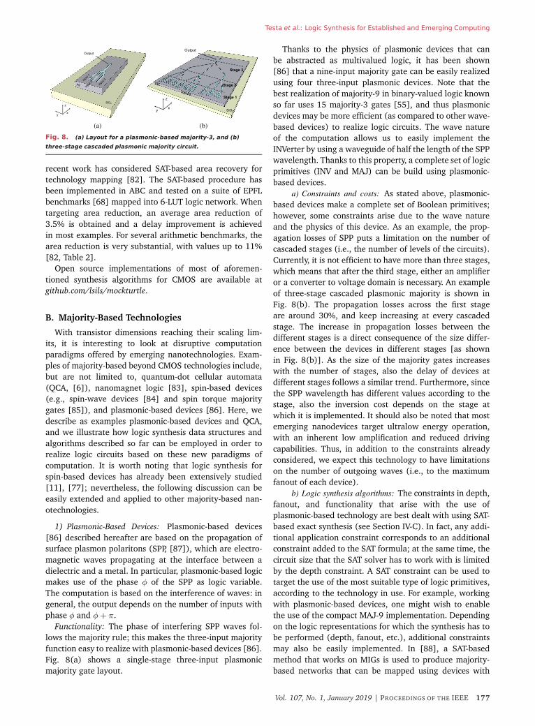
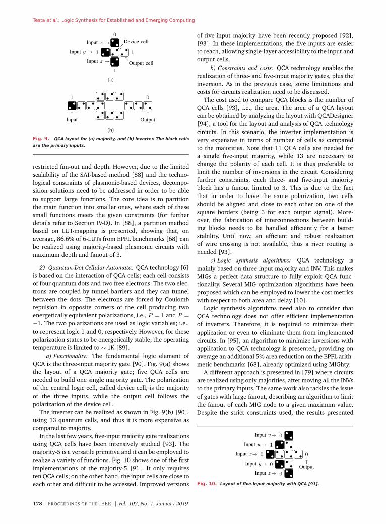
Fig. 9. QCA layout for (a) majority, and (b) inverter. The black cells
are the primary inputs.
restricted fan-out and depth. However, due to the limitedscalability of the SAT-based method [88] and the techno-logical constraints of plasmonic-based devices, decompo-sition solutions need to be addressed in order to be ableto support large functions. The core idea is to partitionthe main function into smaller ones, where each of thesesmall functions meets the given constraints (for furtherdetails refer to Section IV-D). In [88], a partition methodbased on LUT-mapping is presented, showing that, onaverage, 86.6% of 6-LUTs from EPFL benchmarks [68] canbe realized using majority-based plasmonic circuits withmaximum depth and fanout of 3.
2) Quantum-Dot Cellular Automata: QCA technology [6]is based on the interaction of QCA cells; each cell consistsof four quantum dots and two free electrons. The two elec-trons are coupled by tunnel barriers and they can tunnelbetween the dots. The electrons are forced by Coulombrepulsion in opposite corners of the cell producing twoenergetically equivalent polarizations, i.e., P = 1 and P =
−1. The two polarizations are used as logic variables; i.e.,to represent logic 1 and 0, respectively. However, for thesepolarization states to be energetically stable, the operatingtemperature is limited to ∼ 1K [89].
a) Functionality: The fundamental logic element ofQCA is the three-input majority gate [90]. Fig. 9(a) showsthe layout of a QCA majority gate; five QCA cells areneeded to build one single majority gate. The polarizationof the central logic cell, called device cell, is the majorityof the three inputs, while the output cell follows thepolarization of the device cell.
The inverter can be realized as shown in Fig. 9(b) [90],using 13 quantum cells, and thus it is more expensive ascompared to majority.
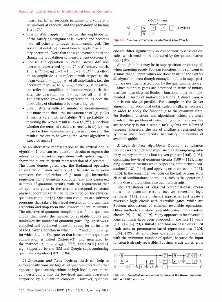
In the last few years, five-input majority gate realizationsusing QCA cells have been intensively studied [93]. Themajority-5 is a versatile primitive and it can be employed torealize a variety of functions. Fig. 10 shows one of the firstimplementations of the majority-5 [91]. It only requiresten QCA cells; on the other hand, the input cells are close toeach other and difficult to be accessed. Improved versions
of five-input majority have been recently proposed [92],[93]. In these implementations, the five inputs are easierto reach, allowing single-layer accessibility to the input andoutput cells.
b) Constraints and costs: QCA technology enables therealization of three- and five-input majority gates, plus theinversion. As in the previous case, some limitations andcosts for circuits realization need to be discussed.
The cost used to compare QCA blocks is the number ofQCA cells [93], i.e., the area. The area of a QCA layoutcan be obtained by analyzing the layout with QCADesigner[94], a tool for the layout and analysis of QCA technologycircuits. In this scenario, the inverter implementation isvery expensive in terms of number of cells as comparedto the majorities. Note that 11 QCA cells are needed fora single five-input majority, while 13 are necessary tochange the polarity of each cell. It is thus preferable tolimit the number of inversions in the circuit. Consideringfurther constraints, each three- and five-input majorityblock has a fanout limited to 3. This is due to the factthat in order to have the same polarization, two cellsshould be aligned and close to each other on one of thesquare borders (being 3 for each output signal). More-over, the fabrication of interconnections between build-ing blocks needs to be handled efficiently for a betterstability. Until now, an efficient and robust realizationof wire crossing is not available, thus a river routing isneeded [93].
c) Logic synthesis algorithms: QCA technology ismainly based on three-input majority and INV. This makesMIGs a perfect data structure to fully exploit QCA func-tionality. Several MIG optimization algorithms have beenproposed which can be employed to lower the cost metricswith respect to both area and delay [10].
Logic synthesis algorithms need also to consider thatQCA technology does not offer efficient implementationof inverters. Therefore, it is required to minimize theirapplication or even to eliminate them from implementedcircuits. In [95], an algorithm to minimize inversions withapplication to QCA technology is presented, providing onaverage an additional 5% area reduction on the EPFL arith-metic benchmarks [68], already optimized using MIGhty.
A different approach is presented in [79] where circuitsare realized using only majorities, after moving all the INVsto the primary inputs. The same work also tackles the issueof gates with large fanout, describing an algorithm to limitthe fanout of each MIG node to a given maximum value.Despite the strict constraints used, the results presented
Fig. 10. Layout of five-input majority with QCA [91].
178 PROCEEDINGS OF THE IEEE | Vol. 107, No. 1, January 2019
Testa et al.: Logic Synthesis for Established and Emerging Computing
in [79] show that having inverter-free circuits enables a3.1× reduction in area delay energy product (ADEP).
Both plasmonic-based devices and QCA offer majoritygates with different arities as primitives. Larger majority-gates can lead to cost reductions if properly exerted bythe logic synthesis algorithm. In general, majority-n logicsynthesis addresses such problems (see, e.g., [54], [96],and [97]), including mapping combinational logic intolarge majority gates and decomposing large majority gatesinto smaller ones.
C. Quantum Computing
In this section, we illustrate how logic synthesistechniques can be used in applications different from con-ventional computing. We show how logic synthesis helpsto compile combinational logic for quantum computers.
Quantum computers are computers that exploit theprinciples of quantum mechanics. Their premise is to exe-cute quantum algorithms, which can be computationallysuperior to their classical counterparts. Several quantumalgorithms have already been conceived, which can har-ness the power of a quantum computer to eventually solvecomplex problems more efficiently. The most prominentone is arguably Shor’s algorithm [98] that can factorizeintegers in polynomial time, whereas for classical com-puting nothing better than a subexponential upper boundis known [99]. Consequently, Shor’s algorithm can breakpublic-key cryptography which is based on the assumptionthat integer factorization is a hard task. Other more genericalgorithms play a significant role in scientific applicationsof high interest. Examples are as follows:
• Grover’s search algorithm [100], which enables fasterdatabase queries;
• the HHL algorithm [101], which brings an exponen-tial speedup to solve linear equations;
• quantum simulation (see, e.g., [102]) to modelatomic-scale interactions efficiently, allowing toapproximate behavior in drugs, organics, and mate-rials in areas such as medicine, chemistry, and engi-neering, respectively.
1) Functionality: A quantum computer consists of anarray of quantum bits, also called qubits, that in contrastto classical bits, can be in a superposition state and can beentangled [7]. Formally, a qubit is in a quantum state thatis a column vector |ϕ〉 =
�αβ
�of two complex numbers α
and β, called amplitudes, such that |α|2 + |β|2 = 1. Thesquared amplitudes |α|2 and |β|2 indicate the probabilitythat the quantum state will collapse to the classical state|0〉 =
�10
�or |1〉 =
�01
�after the qubit is measured. A
quantum state can be transformed into another quantumstate by applying quantum gates, which are representedby 2 × 2 unitary matrices. For example, the Hadamardgate H = (1/
√2)( 1 1
1 −1 ) transforms the classical quantumstate |0〉 into the state (1/
√2)�11
�, which is in the perfect
superposition between 0 and 1. Quantum states over nqubits are represented by a column vector of 2n complex
values αx with x ∈ 2n such that� |αi|2 = 1. Each
squared amplitude |αi|2 indicates the probability that aftermeasurement the n qubits are in classical states x. Quan-tum states can be combined by applying the Kroneckerproduct to produce larger ones, e.g.,
�10
� ⊗ (1/√
2)�11
�=
(1/√
2)
1100
, which represents a 2-qubit state that is in
the perfect superposition between the classical states 00and 01. On the contrary, larger states cannot always berepresented in terms of smaller ones. For example, thereare no two independent qubit states |ϕ1〉 and |ϕ2〉 such that
|ϕ1〉 ⊗ |ϕ2〉 = (1/√
2)
1001
, the state that is in the perfect
superposition between the classical states 00 and 11. Thisphenomenon is called entanglement. Quantum gates thatact on n qubits are represented in terms of 2n × 2n unitarymatrices. One frequently used two-input gate is the CNOTgate that inverts one qubit conditioned on the other qubit.
Its 4 × 4 unitary matrix is
1 0 0 00 1 0 00 0 0 10 0 1 0
.
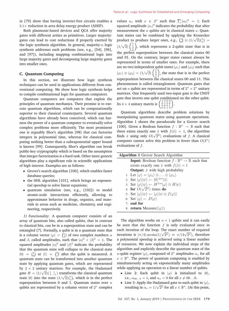
Quantum algorithms describe problem solutions bymanipulating quantum states using quantum operations.Algorithm 1 shows the pseudocode for a Grover search[100]. Given a Boolean function f : B
n → B such thatthere exists exactly one x with f(x) = 1, the algorithmfinds x using only O(
√2n) evaluations of f . A classical
computer cannot solve this problem in fewer than O(2n)
evaluations of f .
Algorithm 1 Grover Search Algorithm
Input: Boolean function f : Bn → B such that
exists exactly one x with f(x) = 1Output: x with high probability
1: Let |ϕ〉 = |ϕ1〉 ⊗ . . .⊗ |ϕn〉2: Set |ϕ〉|ψ〉 ← |0〉⊗n|1〉3: Set |ϕ〉|ψ〉 ← H⊗n|ϕ〉 ⊗H |ψ〉4: for O(
√2n) times do
5: Set |ϕ〉|ψ〉 ← |ϕ〉|ψ ⊕ f(ϕ)〉6: Set |ϕ〉 ← D|ϕ〉7: end for8: return Measure(|ϕ〉)
The algorithm works on n + 1 qubits and it can easilybe seen that the function f is only evaluated once ineach iteration of the loop. The exact number of requirediterations is (π/4) arcsin(1/
√2n) ≈ π/(4
√2n), therefore
a polynomial speedup is achieved using a linear numberof resources. We now explain the individual steps of thealgorithm and explicitly describe the quantum state of then-qubit register |ϕ〉, composed of 2n amplitudes αx for allx ∈ B
n. The power of quantum computing is enabled bysimultaneously acting on exponentially many amplitudeswhile applying an operation to a linear number of qubits.
• Line 2: Each qubit in |ϕ〉 is initialized to |0〉,i.e., α00...0 = 1, and αx = 0 for all x �= 00. . .0.
• Line 3: Apply the Hadamard gate to each qubit in |ϕ〉,resulting in αx = 1/
√2n for all x ∈ B
n. (At this point,
Vol. 107, No. 1, January 2019 | PROCEEDINGS OF THE IEEE 179
Testa et al.: Logic Synthesis for Established and Emerging Computing
measuring |ϕ〉 corresponds to sampling a value x ∈B
n uniform at random; and the probability of findingx is 1/2n.)
• Line 5: When applying f to |ϕ〉, the amplitude αx
of the satisfying assignment is inverted and becomes−αx; all other amplitudes remain unchanged. Theadditional qubit |ψ〉 is used here to apply f as a uni-tary operation. (Note that the sign inversion does notchange the probabilities of measurement outcome.)
• Line 6: The operation D, called Grover diffusionoperator, is described by the 2n × 2n unitary matrixD = H⊗n ⊗ diag(1,−1,−1, . . .,−1) ⊗H⊗n. Its effecton an amplitude is to reflect it with respect to themean value μ =
�x∈Bx αx of all amplitudes, i.e., the
operation maps αx to 2μ − αx. Since αx is negative,the reflection amplifies its absolute value such thatafter the operation |αx| > |αx| for all x ∈ B
x.The difference grows in every iteration, as does theprobability of obtaining x by measuring |ϕ〉.
• Line 8: After a sufficient number of iterations—andnot more than that—the measurement of |ϕ〉 yieldsx with a very high probability. The probability ofreturning the wrong result is in O(1/
√2n). [Checking
whether the returned result is correct is in O(1), sinceit can be done by evaluating f classically once; if theresult turns out to be wrong, the Grover algorithm isexecuted again.]
As an alternative representation to the textual one inAlgorithm 1, one can use quantum circuits to express theinteraction of quantum operations with qubits. Fig. 11shows the quantum circuit representation of Algorithm 1.The boxes denote gates, e.g., the Hadamard operationH and the diffusion operator D. The gate in betweenexpresses the application of f onto |ϕ〉. Instructionsequences for a quantum computer are also expressedin terms of quantum circuits, with the requirement thatall quantum gates in the circuit correspond to actualphysical operations that can be executed on the physicalquantum computer [5]. Quantum compilers are softwareprograms that take a high-level description of a quantumalgorithm and map them into low-level quantum circuits.The objective of quantum compilers is to find a quantumcircuit that meets the number of available qubits andminimizes the number of quantum gates. Fig. 12 shows acompiled and optimized quantum circuit for an instanceof the Grover algorithm in which n = 2 and f = x1 ∧ x2,for which x = 11. The gate set that is used in this quantumcomputation is called Clifford+T [and generated bythe matrices H , T = diag(1, eiπ/4), and CNOT] and is,e.g., supported by the IBM and Google superconductingquantum computers [103], [104].
2) Constraints and Costs: Logic synthesis can help toautomatically translate high-level quantum operations thatappear in quantum algorithms or high-level quantum cir-cuit descriptions into the low-level quantum operationssupported by a quantum computer. However, quantum
Fig. 11. Quantum circuit representation of Algorithm 1.
circuits differ significantly in comparison to classical cir-cuits, which needs to be addressed by design automationtools [105].
Although qubits may be in superposition or entangled,when targeting purely Boolean functions, it is sufficient toassume that all input values are Boolean inside the synthe-sis algorithm, even though entangled qubits in superposi-tion are eventually acted upon by the quantum hardware.
Since quantum gates are described in terms of unitarymatrices, also classical Boolean functions must be imple-mented in terms of unitary operations. A direct transla-tion is not always possible. For example, in the Groveralgorithm, an additional qubit, called ancilla, is necessaryin order to apply the function f to the quantum state.For Boolean functions and algorithms, which are moreinvolved, the problem of determining how many ancillaeare necessary is not a simple task. Qubits are a limitedresource; therefore, the use of ancillae is restricted andsynthesis must find circuits that satisfy the number ofavailable qubits.
3) Logic Synthesis Algorithms: Quantum compilationrequires several different steps, such as decomposing arbi-trary unitary operations into a given gate set [106]–[108],optimizing low-level quantum circuits [109]–[112], map-ping quantum circuits while respecting architectural con-straints [113], [114], and applying error correction [115],[116]. In the remainder, we focus on the task of translatingclassical combinational operations, such as the operation fin the Grover algorithm, into quantum circuits.
The translation of classical combinational opera-tions into quantum circuits involves reversible logicsynthesis [117]. State-of-the-art approaches first create areversible logic circuit with reversible gates, which areBoolean abstractions of classical reversible operations.Other methods translate reversible gates into quantumcircuits [9], [118], [119]. Many approaches for reversiblelogic synthesis have been proposed in the last 15 years(e.g., [120]–[123]). Initial algorithms are based on explicittruth table or permutation-based representations [120],[124], [125]. All algorithms guarantee quantum circuitswith the minimum number of qubits, because the inputfunction is already reversible. But since truth tables grow
Fig. 12. Compiled and optimized instance of the Grover algorithm
for n � � and f � x� ∧ x�.
180 PROCEEDINGS OF THE IEEE | Vol. 107, No. 1, January 2019
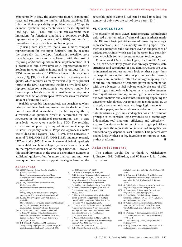
Testa et al.: Logic Synthesis for Established and Emerging Computing
exponentially in size, the algorithms require exponentialspace and runtime in the number of input variables. Thisrules out their applicability to problem sizes of 20 qubitsor more. Symbolic implementations of theses algorithms(see, e.g., [123], [126], and [127]) can overcome theselimitations for functions that have a compact symbolicrepresentation (e.g., in terms of a BDD) and result inreversible circuits with a few number of gates.
By using data structures that allow a more compactrepresentation for the input function, and by relaxingthe constraint that the input function is reversible, morescalable algorithms can be achieved, with the cost ofrequiring additional qubits in their implementation. If itis possible to find a two-level ESOP representation for aBoolean function with n inputs and m outputs (i.e., mESOP representations), ESOP-based reversible logic syn-thesis [33], [34] can find a reversible circuit using m + n
qubits, which requires as many reversible gates as productterms in the ESOP expressions. Finding a two-level ESOPrepresentation for a function is not always simple, butrecent approaches show that it is possible to find represen-tations for functions with up to 32 variables in a reasonableamount of runtime [128].
Scalable reversible logic synthesis can be achieved whenusing a multilevel logic representation for the input func-tion. In so-called hierarchical reversible logic synthesis,a reversible or quantum circuit is determined for sub-structures in the multilevel representation, e.g., a gatein a logic network, or a node in a BDD. The resultingcircuits are composed by using additional ancillae qubitsto store temporary results. Proposed approaches makeuse of decision diagrams [122], [129], logic networks ingeneral [130], AIGs [131], XMGs [132], and most recentlyLUT networks [105]. Hierarchical reversible logic synthesisis as scalable as classical logic synthesis, since it dependson the representation size of the input function. However,this scalability comes at the cost of a significant number ofadditional qubits—often far more than current and near-term quantum computers support. Strategies based on the
reversible pebble game [133] can be used to reduce thenumber of qubits for the cost of more gates [134].
VI. C O N C L U S I O N
The plurality of post-CMOS nanoemerging technologiesenforced a reorientation of classical logic synthesis meth-ods. Different logic primitives are addressed by new logicrepresentations, such as majority-inverter graphs. Exactmethods guarantee valid solutions even in the presence ofvarious constraints, which need to be taken into consider-ation especially for very recent emerging technologies.
Conventional CMOS technologies, such as FPGAs andASICs, can benefit largely from modern logic synthesis datastructures and techniques. If new data structures are usedas intermediate representations, logic synthesis algorithmscan exploit more optimization opportunities which resultsin significant reductions after technology mapping. Fur-thermore, the increase of compute power in combinationwith the advances in SAT solvers enable the use of SAT-based logic synthesis techniques in a scalable manner.Exact synthesis can find optimum logic networks for vari-ous cost functions and constraints, thus being appealing foremerging technologies. Decomposition techniques allow usto apply exact synthesis locally to large logic networks.
In this paper, we have shown a selection of moderndata structures, algorithms, and applications. The commonprinciple is to consider logic synthesis as a technology-independent tool that can—efficiently and effectively—express functionality in terms of small logic primitives,and optimize the representation in terms of an applicationand technology-dependent cost function. This general viewmakes logic synthesis a key ingredient to numerous com-puting platforms. �
A c k n o w l e d g m e n t s
The authors would like to thank A. Mishchenko,R. Brayton, P.-E. Gaillardon, and W. Haaswijk for fruitfuldiscussions.
R E F E R E N C E S[1] (2018). Synopsys Design Compiler Graphical.
[Online]. Available:https://www.synopsys.com/content/dam/synopsys/implementation&signoff/datasheets/dc-graphical-ds.pdf
[2] (2018). Cadence Genus Synthesis Solution.[Online]. Available:https://www.cadence.com/content/dam/cadence-www/global/en_us/documents/tools/digital-design-signoff/genus-synthesis-solution-ds.pdf
[3] (2018). Mentor Graphics Oasys-RTL. [Online].Available:http://s3.mentor.com/public_documents/datasheet/products/ic_nanometer_design/place-route/realtime-designer/realttime-designer.pdf
[4] C. Zhang, P. Li, G. Sun, Y. Guan, B. Xiao, andJ. Cong, “Optimizing FPGA-based acceleratordesign for deep convolutional neural networks,”in Proc. Int. Symp. Field Program. Gate Arrays,2015, pp. 161–170.
[5] F. T. Chong, D. Franklin, and M. Martonosi,“Programming languages and compiler design forrealistic quantum hardware,” Nature, vol. 549,
no. 7671, pp. 180–187, 2017.[6] C. S. Lent, P. D. Tougaw, W. Porod, and
G. H. Bernstein, “Quantum cellular automata,”Nanotechnology, vol. 4, no. 1, pp. 49–57, 1993.
[7] M. A. Nielsen and I. L. Chuang, QuantumComputation and Quantum Information.Cambridge, U.K.: Cambridge Univ. Press, 2000.
[8] T. Toffoli, “Reversible computing,” in Proc. Int.Coll. Automat., Lang., Program., 1980,pp. 632–644.
[9] D. Maslov, “Advantages of using relative-phaseToffoli gates with an application to multiplecontrol Toffoli optimization,” Phys. Rev. A, Gen.Phys., vol. 93, p. 022311, Feb. 2016.
[10] L. G. Amarù, P.-E. Gaillardon, and G. De Micheli,“Majority-inverter graph: A new paradigm forlogic optimization,” IEEE Trans. Comput.-AidedDes. Integr. Circuits Syst., vol. 35, no. 5,pp. 806–819, May 2016.
[11] L. Amaru, P. E. Gaillardon, S. Mitra, and G. DeMicheli, “New logic synthesis as nanotechnologyenabler,” Proc. IEEE, vol. 103, no. 11,pp. 2168–2195, Nov. 2015.
[12] G. De Micheli, Synthesis and Optimization of
Digital Circuits. New York, NY, USA: McGraw-Hill,1994.
[13] R. K. Brayton, G. D. Hachtel, C. McMullen, andA. Sangiovanni-Vincentelli, Logic MinimizationAlgorithms for VLSI Synthesis, vol. 2. Springer,1984.
[14] G. D. Hachtel and F. Somenzi, Logic Synthesis andVerification Algorithms. Springer, 2006.
[15] S. Hassoun and T. Sasao, Logic Synthesis andVerification, vol. 654. Springer, 2012.
[16] E. J. McCluskey, “Minimization of Booleanfunctions,” Bell Syst. Tech. J., The, vol. 35, no. 6,pp. 1417–1444, Nov. 1956.
[17] R. Rudell and A. Sangiovanni-Vincentelli,“Logicsynthesis for VLSI design,” Ph.D. dissertation,Univ. California, Berkeley, Berkeley, CA, USA,1989.
[18] N. Weste and K. Eshraghian, Principles of CMOSVLSI Design. Reading, MA, USA: Addion-Wesley,1993, ch. 8.
[19] T. Sasao, Switching Theory for Logic Synthesis.Springer, 1999.
[20] N. Song and M. A. Perkowski, “Minimization ofexclusive sum-of-products expressions for
Vol. 107, No. 1, January 2019 | PROCEEDINGS OF THE IEEE 181
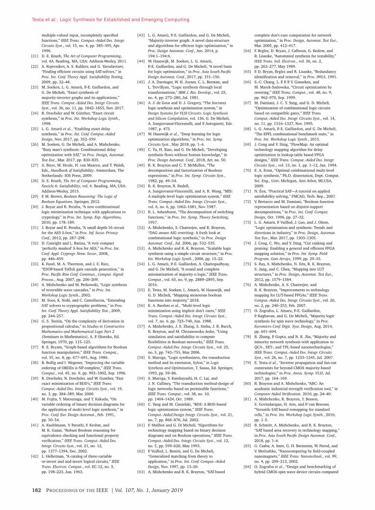
Testa et al.: Logic Synthesis for Established and Emerging Computing
multiple-valued input, incompletely specifiedfunctions,” IEEE Trans. Comput.-Aided Des. Integr.Circuits Syst., vol. 15, no. 4, pp. 385–395, Apr.1996.
[21] D. E. Knuth, The Art of Computer Programming,vol. 4A. Reading, MA, USA: Addison-Wesley, 2011.
[22] A. Kojevnikov, A. S. Kulikov, and G. Yaroslavtsev,“Finding efficient circuits using SAT-solvers,” inProc. Int. Conf. Theory Appl. Satisfiability Testing,2009, pp. 32–44.
[23] M. Soeken, L. G. Amarù, P.-E. Gaillardon, andG. De Micheli, “Exact synthesis ofmajority-inverter graphs and its applications,”IEEE Trans. Comput.-Aided Des. Integr. CircuitsSyst., vol. 36, no. 11, pp. 1842–1855, Nov. 2017.
[24] R. Drechsler and W. Günther, “Exact circuitsynthesis,” in Proc. Int. Workshop Logic Synth.,1998.
[25] L. G. Amarù et al., “Enabling exact delaysynthesis,” in Proc. Int. Conf. Comput.-AidedDesign, Nov. 2017, pp. 352–359.
[26] M. Soeken, G. De Micheli, and A. Mishchenko,“Busy man’s synthesis: Combinational delayoptimization with SAT,” in Proc. Design, Automat.Test Eur., Mar. 2017, pp. 830–835.
[27] A. Biere, M. Heule, H. van Maaren, and T. Walsh,Eds., Handbook of Satisfiability. Amsterdam, TheNetherlands: IOS Press, 2009.
[28] D. E. Knuth, The Art of Computer Programming,Fascicle 6: Satisfiability, vol. 4. Reading, MA, USA:Addison-Wesley, 2015.
[29] F. M. Brown, Boolean Reasoning: The Logic ofBoolean Equations. Springer, 2012.
[30] J. Boyar and R. Peralta, “A new combinationallogic minimization technique with applications tocryptology,” in Proc. Int. Symp. Exp. Algorithms,2010, pp. 178–189.
[31] J. Boyar and R. Peralta, “A small depth-16 circuitfor the AES S-box,” in Proc. Inf. Secur. PrivacyConf., 2012, pp. 287–298.
[32] D. Canright and L. Batina, “A very compact‘perfectly masked’ S-box for AES,” in Proc. Int.Conf. Appl. Cryptogr. Netw. Secur., 2008,pp. 446–459.
[33] K. Fazel, M. A. Thornton, and J. E. Rice,“ESOP-based Toffoli gate cascade generation,” inProc. Pacific Rim Conf. Commun., Comput. SignalProcess., Aug. 2007, pp. 206–209.
[34] A. Mishchenko and M. Perkowski, “Logic synthesisof reversible wave cascades,” in Proc. Int.Workshop Logic Synth., 2002.
[35] M. Soos, K. Nohl, and C. Castelluccia, “ExtendingSAT solvers to cryptographic problems,” in Proc.Int. Conf. Theory Appl. Satisfiability Test., 2009,pp. 244–257.
[36] G. S. Tseitin, “On the complexity of derivation inpropositional calculus,” in Studies in ConstructiveMathematics and Mathematical Logic Part 2(Seminars in Mathematics), A. P. Slisenko, Ed.Springer, 1970, pp. 115–125.
[37] R. E. Bryant, “Graph-based algorithms for Booleanfunction manipulation,” IEEE Trans. Comput.,vol. 35, no. 8, pp. 677–691, Aug. 1986.
[38] B. Bollig and I. Wegener, “Improving the variableordering of OBDDs is NP-complete,” IEEE Trans.Comput., vol. 45, no. 9, pp. 993–1002, Sep. 1996.
[39] R. Drechsler, N. Drechsler, and W. Gunther, “Fastexact minimization of BDD’s,” IEEE Trans.Comput.-Aided Des. Integr. Circuits Syst., vol. 19,no. 3, pp. 384–389, Mar. 2000.
[40] M. Fujita, Y. Matsunaga, and T. Kakuda, “Onvariable ordering of binary decision diagrams forthe application of multi-level logic synthesis,” inProc. Conf. Eur. Design Automat., Feb. 1991,pp. 50–54.
[41] A. Kuehlmann, V. Paruthi, F. Krohm, andM. K. Ganai, “Robust Boolean reasoning forequivalence checking and functional propertyverification,” IEEE Trans. Comput.-Aided Des.Integr. Circuits Syst., vol. 21, no. 12,pp. 1377–1394, Dec. 2002.
[42] L. Hellerman, “A catalog of three-variableor-invert and and-invert logical circuits,” IEEETrans. Electron. Comput., vol. EC-12, no. 3,pp. 198–223, Jun. 1963.
[43] L. G. Amarù, P.-E. Gaillardon, and G. De Micheli,“Majority-inverter graph: A novel data-structureand algorithms for efficient logic optimization,” inProc. Design Automat. Conf., Jun. 2014, p.194:1–194:6.
[44] W. Haaswijk, M. Soeken, L. G. Amarù,P.-E. Gaillardon, and G. De Micheli, “A novel basisfor logic optimization,” in Proc. Asia South PacificDesign Automat. Conf., 2017, pp. 151–156.
[45] J. A. Darringer, W. H. Joyner, C. L. Berman, andL. Trevillyan, “Logic synthesis through localtransformations,” IBM J. Res. Develop., vol. 25,no. 4, pp. 272–280, Jul. 1981.
[46] A. J. de Geus and D. J. Gregory, “The Socrateslogic synthesis and optimization system,” inDesign Systems for VLSI Circuits: Logic Synthesisand Silicon Compilation, vol. 136, G. De Micheli,A. Sangiovanni-Vincentelli, and P. Antognetti, Eds.1987, p. 473.
[47] W. Haaswijk et al., “Deep learning for logicoptimization algorithms,” in Proc. Int. Symp.Circuits Syst., May 2018, pp. 1–4.
[48] C. Yu, H. Xiao, and G. De Micheli, “Developingsynthesis flows without human knowledge,” inProc. Design Automat. Conf., 2018, Art. no. 50.
[49] R. K. Brayton and C. T. McMullen, “Thedecomposition and factorization of Booleanexpressions,” in Proc. Int. Symp. Circuits Syst.,1982, pp. 49–54.
[50] R. K. Brayton, R. Rudell,A. Sangiovanni-Vincentelli, and A. R. Wang, “MIS:A multiple-level logic optimization system,” IEEETrans. Comput.-Aided Des. Integr. Circuits Syst.,vol. 6, no. 6, pp. 1062–1081, Nov. 1987.
[51] R. L. Ashenhurst, “The decomposition of switchingfunctions,” in Proc. Int. Symp. Theory Switching,1957.
[52] A. Mishchenko, S. Chatterjee, and R. Brayton,“DAG-aware AIG rewriting: A fresh look atcombinational logic synthesis,” in Proc. DesignAutomat. Conf., Jul. 2006, pp. 532–535.
[53] A. Mishchenko and R. K. Brayton, “Scalable logicsynthesis using a simple circuit structure,” in Proc.Int. Workshop Logic Synth., 2006, pp. 15–22.
[54] L. G. Amarù, P.-E. Gaillardon, A. Chattopadhyay,and G. De Micheli, “A sound and completeaxiomatization of majority-n logic,” IEEE Trans.Comput., vol. 65, no. 9, pp. 2889–2895, Sep.2016.
[55] E. Testa, M. Soeken, L. Amarù, W. Haaswijk, andG. D. Micheli, “Mapping monotone booleanfunctions into majority,” 2018.
[56] K. A. Bartlett et al., “Multi-level logicminimization using implicit don’t cares,” IEEETrans. Comput.-Aided Des. Integr. Circuits Syst.,vol. 7, no. 6, pp. 723–740, Jun. 1988.
[57] A. Mishchenko, J. S. Zhang, S. Sinha, J. R. Burch,R. Brayton, and M. Chrzanowska-Jeske, “Usingsimulation and satisfiability to computeflexibilities in Boolean networks,” IEEE Trans.Comput.-Aided Des. Integr. Circuits Syst., vol. 25,no. 5, pp. 743–755, May 2006.
[58] S. Muroga, “Logic synthesizers, the transductionmethod and its extension, Sylon,” in LogicSynthesis and Optimization, T. Sasao, Ed. Springer,1993, pp. 59–86.
[59] S. Muroga, Y. Kambayashi, H. C. Lai, andJ. N. Culliney, “The transduction method-design oflogic networks based on permissible functions,”IEEE Trans. Comput., vol. 38, no. 10,pp. 1404–1424, Oct. 1989.
[60] C. Yang and M. Ciesielski, “BDS: A BDD-basedlogic optimization system,” IEEE Trans.Comput.-Aided Design Integr. Circuits Syst., vol. 21,no. 7, pp. 866–876, Jul. 2002.
[61] F. Mailhot and G. Di Micheli, “Algorithms fortechnology mapping based on binary decisiondiagrams and on Boolean operations,” IEEE Trans.Comput.-Aided Des. Integr. Circuits Syst., vol. 12,no. 5, pp. 599–620, May 1993.
[62] P. Vuillod, L. Benini, and G. De Micheli,“Generalized matching from theory toapplication,” in Proc. Int. Conf. Comput.-AidedDesign, Nov. 1997, pp. 13–20.
[63] A. Mishchenko and R. K. Brayton, “SAT-based
complete don’t-care computation for networkoptimization,” in Proc. Design, Automat. Test Eur.,Mar. 2005, pp. 412–417.
[64] F. Brglez, D. Bryan, J. Calhoun, G. Kedem, andR. Lisanke, “Automated synthesis for testability,”IEEE Trans. Ind. Electron., vol. 36, no. 2,pp. 263–277, May 1989.
[65] F. D. Bryan, Brglez and R. Lisanke, “Redundancyidentification and removal,” in Proc. IWLS, 1991.
[66] S.-C. Chang, L. P. P. P. V. Ginneken, andM. Marek-Sadowska, “Circuit optimization byrewiring,” IEEE Trans. Comput., vol. 48, no. 9,pp. 962–970, Sep. 1999.
[67] M. Damiani, J. C. Y. Yang, and G. D. Micheli,“Optimization of combinational logic circuitsbased on compatible gates,” IEEE Trans.Comput.-Aided Des. Integr. Circuits Syst., vol. 14,no. 11, pp. 1316–1327, Nov. 1995.
[68] L. G. Amarù, P.-E. Gaillardon, and G. De Micheli,“The EPFL combinational benchmark suite,” inProc. Int. Workshop Logic Synth., 2015.
[69] J. Cong and Y. Ding, “FlowMap: An optimaltechnology mapping algorithm for delayoptimization in lookup-table based FPGAdesigns,” IEEE Trans. Comput.-Aided Des. Integr.Circuits Syst., vol. 13, no. 1, pp. 1–12, Jan. 1994.
[70] E. A. Ernst, “Optimal combinational multi-levellogic synthesis,” Ph.D. dissertation, Dept. Comput.Sci. Eng., Univ. Michigan, Ann Arbor, MI,USA,2009.
[71] N. Éen, “Practical SAT—A tutorial on appliedsatisfiability solving,” FMCAD, Tech. Rep., 2007.
[72] V. Bertacco and M. Damiani, “Boolean functionrepresentation based on disjoint-supportdecompositions,” in Proc. Int. Conf. Comput.Design, Oct. 1996, pp. 27–32.
[73] L. G. Amarù, P. Vuillod, J. Luo, and J. Olson,“Logic optimization and synthesis: Trends anddirections in industry,” in Proc. Design, Automat.Test Eur., Mar. 2017, pp. 1303–1305.
[74] J. Cong, C. Wu, and Y. Ding, “Cut ranking andpruning: Enabling a general and efficient FPGAmapping solution,” in Proc. Int. Symp. FieldProgram. Gate Arrays, 1999, pp. 29–35.
[75] S. Ray, A. Mishchenko, N. Eén, R. K. Brayton,S. Jang, and C. Chen, “Mapping into LUTstructures,” in Proc. Design, Automat. Test Eur.,2012, pp. 1579–1584.
[76] A. Mishchenko, A. S. Chatterjee, andR. K. Brayton, “Improvements to technologymapping for LUT-based FPGAs,” IEEE Trans.Comput.-Aided Des. Integr. Circuits Syst., vol. 26,no. 2, pp. 240–253, Feb. 2007.
[77] O. Zografos, L. Amaru, P.-E. Gaillardon,P. Raghavan, and G. De Micheli, “Majority logicsynthesis for spin wave technology,” in Proc.Euromicro Conf. Digit. Syst. Design, Aug. 2014,pp. 691–694.
[78] R. Zhang, P. Gupta, and N. K. Jha, “Majority andminority network synthesis with application toQCA-, SET-, and TPL-based nanotechnologies,”IEEE Trans. Comput.-Aided Des. Integr. CircuitsSyst., vol. 26, no. 7, pp. 1233–1245, Jul. 2007.
[79] E. Testa et al., “Inverter propagation and fan-outconstraints for beyond-CMOS majority-basedtechnologies,” in Proc. Annu. Symp. VLSI, Jul.2017, pp. 164–169.
[80] R. Brayton and A. Mishchenko, “ABC: Anacademic industrial-strength verification tool,” inComputer Aided Verification. 2010, pp. 24–40.
[81] A. Mishchenko, R. Brayton, T. Besson,S. Govindarajan, H. Arts, and P. van Besouw,“Versatile SAT-based remapping for standardcells,” in Proc. Int. Workshop Logic Synth., 2016,pp. 1–5.
[82] B. Schmitt, A. Mishchenko, and R. K. Brayton,“SAT-based area recovery in technology mapping,”in Proc. Asia South Pacific Design Automat. Conf.,2018, pp. 1–6.
[83] G. Csaba, A. Imre, G. H. Bernstein, W. Porod, andV. Metlushko, “Nanocomputing by field-couplednanomagnets,” IEEE Trans. Nanotechnol., vol. 99,no. 4, pp. 209–213, 2002.
[84] O. Zografos et al., “Design and benchmarking ofhybrid CMOS-spin wave device circuits compared
182 PROCEEDINGS OF THE IEEE | Vol. 107, No. 1, January 2019
Testa et al.: Logic Synthesis for Established and Emerging Computing
to 10 nm CMOS,” in Proc. Int. Conf. Nanotechnol.,Jul. 2015, pp. 686–689.
[85] D. E. Nikonov, G. I. Bourianoff, and T. Ghani,“Proposal of a spin torque majority gate logic,”IEEE Electron Device Lett., vol. 32, no. 8,pp. 1128–1130, Aug. 2011.
[86] S. Dutta et al., “Proposal for nanoscale cascadedplasmonic majority gates for non-Booleancomputation,” Sci. Rep., vol. 7, no. 1, p. 17866,2017.
[87] W. L. Barnes, A. Dereux, and T. W. Ebbesen,“Surface plasmon subwavelength optics,” Nature,vol. 424, no. 6950, pp. 824–830, 2003.
[88] E. Testa, M. Soeken, O. Zografos, F. Catthoor, andG. De Micheli, “Exact synthesis for logic synthesisapplications with complex constraints,” in Proc.Int. Workshop Logic Synth., 2017.
[89] C. S. Lent and P. D. Tougaw, “A device architecturefor computing with quantum dots,” Proc. IEEE,vol. 85, no. 4, pp. 541–557, Apr. 1997.
[90] P. D. Tougaw and C. S. Lent, “Logical devicesimplemented using quantum cellular automata,”Appl. Phys. Lett., vol. 75, no. 3, pp. 1818–1825,1993.
[91] K. Navi, R. Farazkish, S. Sayedsalehi, andM. R. Azghadi, “A new quantum-dot cellularautomata full-adder,” Microelectron. J., vol. 41,no. 12, pp. 820–826, 2010.
[92] S. Sheikhfaal, S. Angizi, S. Sarmadi,M. H. Moaiyeri, and S. Sayedsalehi, “Designingefficient QCA logical circuits with powerdissipation analysis,” Microelectron. J., vol. 46,no. 6, pp. 462–471, Jun. 2015.
[93] T. N. Sasamal, A. K. Singh, and A. Mohan, “Anoptimal design of full adder based on 5-inputmajority gate in coplanar quantum-dot cellularautomata,” Optik, vol. 127, no. 20,pp. 8576–8591, Oct. 2016.
[94] K. Walus, T. J. Dysart, G. A. Jullien, andR. A. Budiman, “QCADesigner: A rapid design andsimulation tool for quantum-dot cellularautomata,” IEEE Trans. Nanotechnol., vol. 3, no. 1,pp. 26–31, Mar. 2004.
[95] E. Testa et al., “Inversion optimization inmajority-inverter graphs,” in Proc. Int. Symp.Nanosc. Architect., Jul. 2016, pp. 15–20.
[96] S. Amarel, G. E. Cooke, and R. O. Winder,“Majority gate networks,” IEEE Trans. Electron.Comput., vol. 13, no. 1, pp. 4–13, 1964.
[97] A. Chattopadhyay, L. G. Amarù, M. Soeken,P.-E. Gaillardon, and G. De Micheli, “Notes onmajority Boolean algebra,” in Proc. Int. Symp.Multiple-Valued Logic, May 2016, pp. 50–55.
[98] P. W. Shor, “Polynomial-time algorithms for primefactorization and discrete logarithms on aquantum computer,” SIAM J. Comput., vol. 26,no. 5, pp. 1484–1509, 1997.
[99] C. Pomerance, “A tale of two sieves,” Notices AMS,vol. 43, no. 12, pp. 1473–1485, 1996.
[100] L. K. Grover, “A fast quantum mechanicalalgorithm for database search,” in Proc. Symp.Theory Comput., 1996, pp. 212–219.
[101] A. W. Harrow, A. Hassidim, and S. Lloyd,“Quantum algorithm for linear systems ofequations,” Phys. Rev. Lett., vol. 103, no. 15, p.150502, Oct. 2009.
[102] T. H. Johnson, S. R. Clark, and D. Jaksch, “What isa quantum simulator?” EPJ Quantum Technol.,vol. 1, no. 10, pp. 1–12, 2014.
[103] N. M. Linke et al., “Experimental comparison oftwo quantum computing architectures,” Proc. Nat.Acad. Sci. USA, vol. 114, no. 13, pp. 3305–3310,2017.
[104] I. L. Markov, A. Fatima, S. V. Isakov, and S. Boixo(2018). “Quantum supremacy is both closer andfarther than it appears.” [Online]. Available:https://arxiv.org/abs/1807.10749
[105] M. Soeken, M. Roetteler, N. Wiebe, and G. DeMicheli, “Hierarchical reversible logic synthesisusing LUTs,” in Proc. Design Automat. Conf., 2017,pp. 78:1–78:6.
[106] V. Kliuchnikov and J. Yard (2015). “A frameworkfor exact synthesis.” [Online]. Available:https://arxiv.org/abs/1504.04350
[107] S. Forest, D. Gosset, V. Kliuchnikov, andD. McKinnon, “Exact synthesis of single-qubitunitaries over Clifford-cyclotomic gate sets,”J. Math. Phys., vol. 56, no. 8, p. 082201, 2015.
[108] A. Bocharov, Y. Gurevich, and K. M. Svore,“Efficient decomposition of single-qubit gates intoV basis circuits,” Phys. Rev. A, Gen. Phys., vol. 88,Jul. 2013, Art. no. 012313.
[109] Y. Nam, N. J. Ross, Y. Su, A. M. Childs, andD. Maslov, “Automated optimization of largequantum circuits with continuous parameters,”Quantum Inf., vol. 4, no. 23, pp. 1–12, 2018.
[110] D. Maslov, “Basic circuit compilation techniquesfor an ion-trap quantum machine,” Quantum Inf.,vol. 19, Feb. 2017, Art. no. 023035.
[111] L. Heyfron and E. T. Campbell (2018). “Anefficient quantum compiler that reduces T count.”[Online]. Available:https://arxiv.org/abs/1712.01557
[112] M. Amy, D. Maslov, and M. Mosca,“Polynomial-time T-depth optimization of cliffordTcircuits via matroid partitioning,” IEEE Trans.Comput.-Aided Des. Integr. Circuits Syst., vol. 33,no. 10, pp. 1476–1489, Oct. 2014.
[113] A. Zulehner, A. Paler, and R. Wille (2018). “Anefficient methodology for mapping quantumcircuits to the IBM QX architectures.” [Online].Available: https://arxiv.org/abs/1712.04722
[114] L. Lao et al. (2018). “Mapping of latticesurgery-based quantum circuits on surface codearchitectures.” [Online]. Available:https://arxiv.org/abs/1805.11127
[115] C. Horsman, A. G. Fowler, S. Devitt, and R. VanMeter, “Surface code quantum computing bylattice surgery,” Quantum Inf., vol. 14, pp. 1–27,Dec. 2012.
[116] R. Chao and B. W. Reichardt (2017).“Fault-tolerant quantum computation with fewqubits.” [Online]. Available:https://arxiv.org/abs/1705.05365
[117] M. Saeedi and I. L. Markov, “Synthesis andoptimization of reversible circuits—A survey,”ACM Comput. Surveys, vol. 45, no. 2,pp. 21:1–21:34, 2013.
[118] A. Barenco et al., “Elementary gates for quantumcomputation,” Phys. Rev. A, Gen. Phys., vol. 52,no. 5, p. 3457, 1995.
[119] N. Abdessaied, M. Amy, M. Soeken, and
R. Drechsler, “Technology mapping of reversiblecircuits to cliffordT quantum circuits,” in Proc. Int.Symp. Multiple-Valued Logic, May 2016,pp. 150–155.
[120] D. M. Miller, D. Maslov, and G. W. Dueck, “Atransformation based algorithm for reversiblelogic synthesis,” in Proc. Design Automat. Conf.,Jun. 2003, pp. 318–323.
[121] V. V. Shende, A. K. Prasad, I. L. Markov, andJ. P. Hayes, “Synthesis of reversible logic circuits,”IEEE Trans. Comput.-Aided Des. Integr. CircuitsSyst., vol. 22, no. 6, pp. 710–722, Jun. 2003.
[122] R. Wille and R. Drechsler, “BDD-based synthesis ofreversible logic for large functions,” in Proc. Des.Automat. Conf., Jul. 2009, pp. 270–275.
[123] M. Soeken, R. Wille, C. Hilken, N. Przigoda, andR. Drechsler, “Synthesis of reversible circuits withminimal lines for large functions,” in Proc. AsiaSouth Pacific Des. Automat. Conf., Jan./Feb. 2012,pp. 85–92.
[124] A. De Vos and Y. Van Rentergem, “Youngsubgroups for reversible computers,” Adv. Math.Commun., vol. 2, no. 2, pp. 183–200,2008.
[125] M. Saeedi, M. S. Zamani, M. Sedighi, andZ. Sasanian, “Reversible circuit synthesis using acycle-based approach,” ACM J. Emerg. Technol.Comput. Syst., vol. 6, no. 4, p. 13, 2010.
[126] M. Soeken, L. Tague, G. W. Dueck, andR. Drechsler, “Ancilla-free synthesis of largereversible functions using binary decisiondiagrams,” J. Symbolic Comput., vol. 73, pp. 1–26,Mar./Apr. 2016.
[127] M. Soeken, G. W. Dueck, and D. M. Miller, “A fastsymbolic transformation based algorithm forreversible logic synthesis,” in Proc. Int. Conf.Reversible Comput., 2016, pp. 307–321.
[128] B. Schmitt, M. Soeken, A. Mishchenko, andG. D. Micheli, “Scaling up collapsing into ESOPexpressions enables ancilla-free quantumcompilation,” 2018.
[129] M. Soeken, R. Wille, and R. Drechsler,“Hierarchical synthesis of reversible circuits usingpositive and negative Davio decomposition,” inProc. Int. Design Test Symp., 2010, pp. 143–148.
[130] M. Rawski, “Application of functionaldecomposition in synthesis of reversible circuits,”in Proc. Int. Conf. Reversible Comput., 2015,pp. 285–290.
[131] M. Soeken and A. Chattopadhyay, “Unlockingefficiency and scalability of reversible logicsynthesis using conventional logic synthesis,” inProc. Design Automat. Conf., Jun. 2016,pp. 149:1–149:6.
[132] M. Soeken, M. Roetteler, N. Wiebe, and G. DeMicheli, “Design automation and design spaceexploration for quantum computers,” in Proc.Design, Automat. Test Eur., 2017,pp. 470–475.
[133] C. H. Bennett, “Time/space trade-offs forreversible computation,” SIAM J. Comput., vol. 18,no. 4, pp. 766–776, 1989.
[134] A. Parent, M. Roetteler, and K. M. Svore, “REVS: Atool for space-optimized reversible circuitsynthesis,” in Proc. Int. Conf. Reversible Comput.,2017, pp. 90–101.
A B O U T T H E A U T H O R S
Eleonora Testa (Student Member, IEEE)received the B.Sc. degree in physical engi-neering from the Politecnico di Torino, Turin,Italy, in 2013 and the joint M.Sc. degree inmicro and nanotechnologies for integratedsystems from Politecnico di Torino (Italy),Grenoble INP (France), and EPFL (Switzer-land) in 2015. Currently, she is workingtoward the Ph.D. degree at the IntegratedSystems Laboratory at EPFL, Switzerland.Her research interests include logic synthesis, electronic design
automation, and post-CMOS technologies.
Mathias Soeken (Member, IEEE) receivedthe Ph.D. degree in computer science andengineering from the University of Bremen,Bremen, Germany, in 2013.He is a Scientist at the École Polytechnique
Fédéderale de Lausanne (EPFL), Lausanne,Switzerland. His current research interestsinclude the many aspects of logic synthe-sis and formal verification. He investigatesconstraint-based techniques in logic synthesis and industrial-strength design automation for quantum computing. He is activelymaintaining the logic synthesis frameworks CirKit and RevKit.
Vol. 107, No. 1, January 2019 | PROCEEDINGS OF THE IEEE 183
Testa et al.: Logic Synthesis for Established and Emerging Computing
Dr. Soeken received a scholarship from the German AcademicScholarship Foundation. He has been serving as TPC member forseveral conferences, including DAC, DATE, and ICCAD and is areviewer for Mathematical Reviews as well as for several journals.
Luca Gaetano Amarù (Member, IEEE)received the B.S. and M.S. degrees inelectronic engineering from the Politecnicodi Torino, Turin, Italy, in 2009 and 2011,respectively, and the Ph.D. degree in com-puter science from the Swiss Federal Insti-tute of Technology Lausanne, Lausanne,Switzerland, in 2015.He is a Staff R&D Engineer in the Design
Group, Synopsys Inc., Mountain View, CA, USA, where he is respon-sible for designing efficient data structures and algorithms for logicsynthesis. Prior to joining Synopsys, he was a visiting researcherat Stanford University and research assistant at EPFL. His currentresearch interests include electronic design automation, logic incomputer science, and beyond CMOS technologies.Dr. Amaru was a recipient of the IEEE TCAD Donald O. Pederson
Best Paper Award in 2018, the EDAA Outstanding DissertationAward in 2015, the Best Presentation Award at FETCH conference in2013, and a Best Paper Award Nomination at ASP-DAC conference in2013. He received fellowships and research contribution awards atEPFL. He has been serving as TPC member for several conferences,including DATE, IWLS and DSD. He is a reviewer for several IEEEjournals.
Giovanni De Micheli (Fellow, IEEE) isProfessor and Director of the Institute ofElectrical Engineering, École PolytechniqueFédéderale de Lausanne (EPFL), Lausanne,Switzerland. His research interests includeseveral aspects of design technologies forintegrated circuits and systems, such assynthesis for emerging technologies, net-works on chips, and 3-D integration.Prof. De Micheli is a Fellow of the Association for Computing
Machinery (ACM) and a member of the Academia Europaea andan International Honorary member of the American Academy ofArts and Sciences. He is the recipient of the 2016 IEEE/CS HarryGoode award for seminal contributions to design and design toolsof networks on chips, the 2016 EDAA Lifetime Achievement Award,the 2012 IEEE/CAS Mac Van Valkenburg award for contributions totheory, practice, and experimentation in design methods and tools,the 2003 IEEE Emanuel Piore Award for contributions to computer-aided synthesis of digital systems, and the D. Pederson Award forthe best paper in the IEEE Transactions on Computer-Aided Designand ICAS in 1987 and 2018.
184 PROCEEDINGS OF THE IEEE | Vol. 107, No. 1, January 2019