Embed Size (px)
Citation preview

LInnovative
Switching & Control
OGO! -
Introduction
Getting started
Integrated functions
Operation on device
LOGO! Soft Comfort V7.0
Communication
I IA AS S MP1© Siemens AG 2012 – Subject to change
LOGO! Logic Module
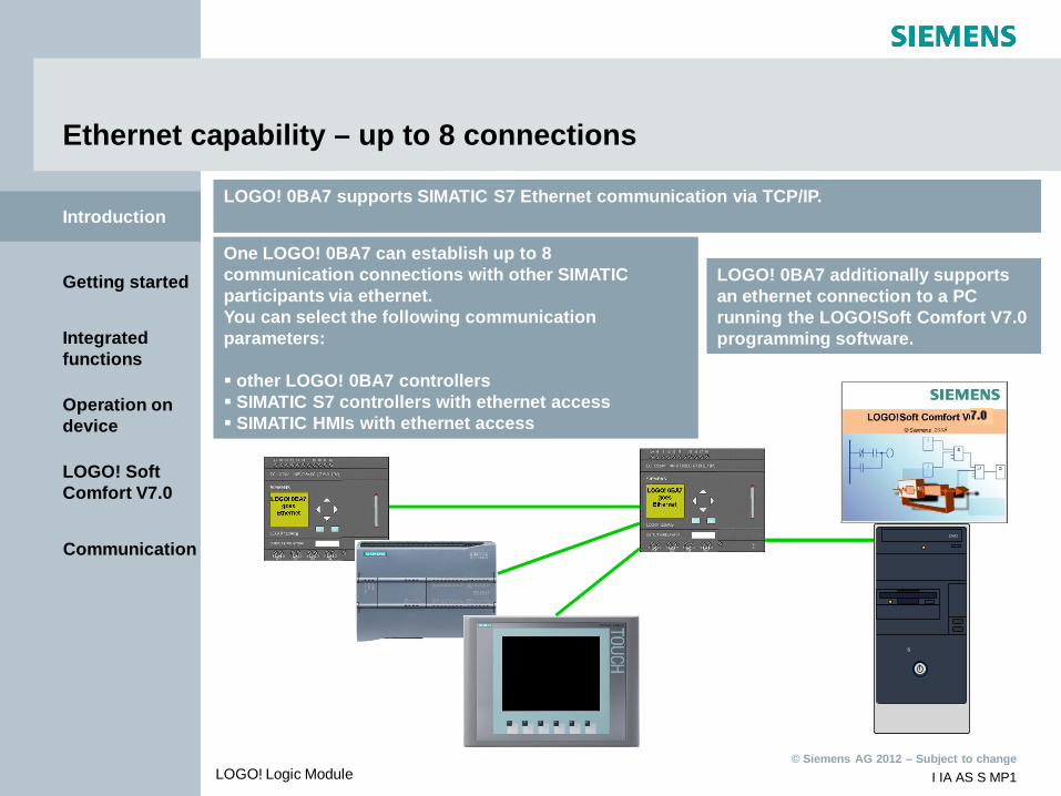
Ethernet capability – up to 8 connections
Introduction
One LOGO! 0BA7 can establish up to 8 communication connections with other SIMATIC participants via ethernet.You can select the following communication parameters:
other LOGO! 0BA7 controllersSIMATIC S7 controllers with ethernet accessSIMATIC HMIs with ethernet access
LOGO! 0BA7 additionally supports an ethernet connection to a PC running the LOGO!Soft Comfort V7.0 programming software.
LOGO! 0BA7 supports SIMATIC S7 Ethernet communication via TCP/IP.
s
DVD
s
DVD
Introduction
Getting started
Integrated functions
Operation on device
LOGO! Soft Comfort V7.0
Communication
I IA AS S MP1© Siemens AG 2012 – Subject to change
LOGO! Logic Module
Simultaneous use of the office network and LOGO! communication via an USB Ethernet adapter
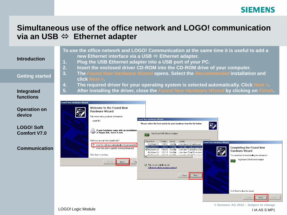
To use the office network and LOGO! Communication at the same time it is useful to add anew Ethernet interface via a USB Ethernet adapter.
1. Plug the USB Ethernet adapter into a USB port of your PC.2. Insert the enclosed driver CD-ROM into the CD-ROM drive of your computer.3. The Found New Hardware Wizard opens. Select the Recommended installation and
click Next >.4. The required driver for your operating system is selected automatically. Click Next >.5. After installing the driver, close the Found New Hardware Wizard by clicking on Finish.
Getting started
Introduction
Getting started
Integrated functions
Operation on device
LOGO! Soft Comfort V7.0
Communication
I IA AS S MP1© Siemens AG 2012 – Subject to change
LOGO! Logic Module
How do I set up the communication between my PC and the LOGO! 0BA7?
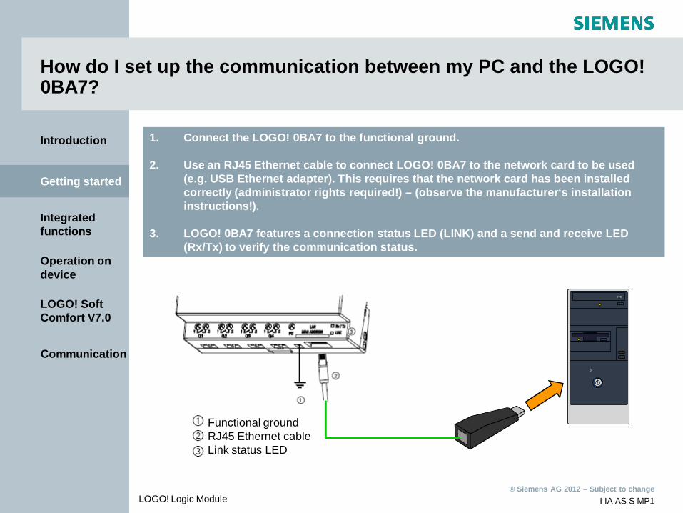
1. Connect the LOGO! 0BA7 to the functional ground.
2. Use an RJ45 Ethernet cable to connect LOGO! 0BA7 to the network card to be used (e.g. USB Ethernet adapter). This requires that the network card has been installed correctly (administrator rights required!) – (observe the manufacturer‘s installation instructions!).
3. LOGO! 0BA7 features a connection status LED (LINK) and a send and receive LED (Rx/Tx) to verify the communication status.
s
DVD
s
DVD
Functional ground RJ45 Ethernet cableLink status LED
Getting started
Introduction
Getting started
Integrated functions
Operation on device
LOGO! Soft Comfort V7.0
Communication
I IA AS S MP1© Siemens AG 2012 – Subject to change
LOGO! Logic Module
IP address assignment of LOGO! 0BA7
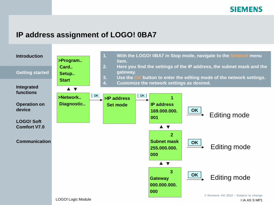
1. With the LOGO! 0BA7 in Stop mode, navigate to the Network menu item.
2. Here you find the settings of the IP address, the subnet mask and the gateway.
3. Use the OK button to enter the editing mode of the network settings.4. Customize the network settings as desired.
Editing mode
Editing mode
Editing mode
OK
OK
OK
>Program..Card..Setup..Start
>Network..Diagnostic..
>IP addressSet mode
1IP address169.000.000.001
2Subnet mask255.000.000.000
3Gateway000.000.000.000
Getting started
Introduction
Getting started
Integrated functions
Operation on device
LOGO! Soft Comfort V7.0
Communication
I IA AS S MP1© Siemens AG 2012 – Subject to change
LOGO! Logic Module
IP address assignment of the PC
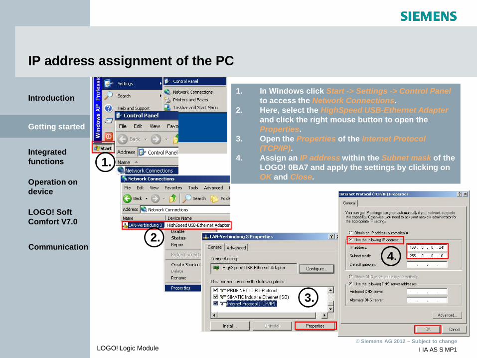
1. In Windows click Start -> Settings -> Control Panel to access the Network Connections.
2. Here, select the HighSpeed USB-Ethernet Adapterand click the right mouse button to open the Properties.
3. Open the Properties of the Internet Protocol (TCP/IP).
4. Assign an IP address within the Subnet mask of the LOGO! 0BA7 and apply the settings by clicking on OK and Close.
1.
2.
3.
4.
Getting started
Introduction
Getting started
Integrated functions
Operation on device
LOGO! Soft Comfort V7.0
Communication
I IA AS S MP1© Siemens AG 2012 – Subject to change
LOGO! Logic Module
Online test
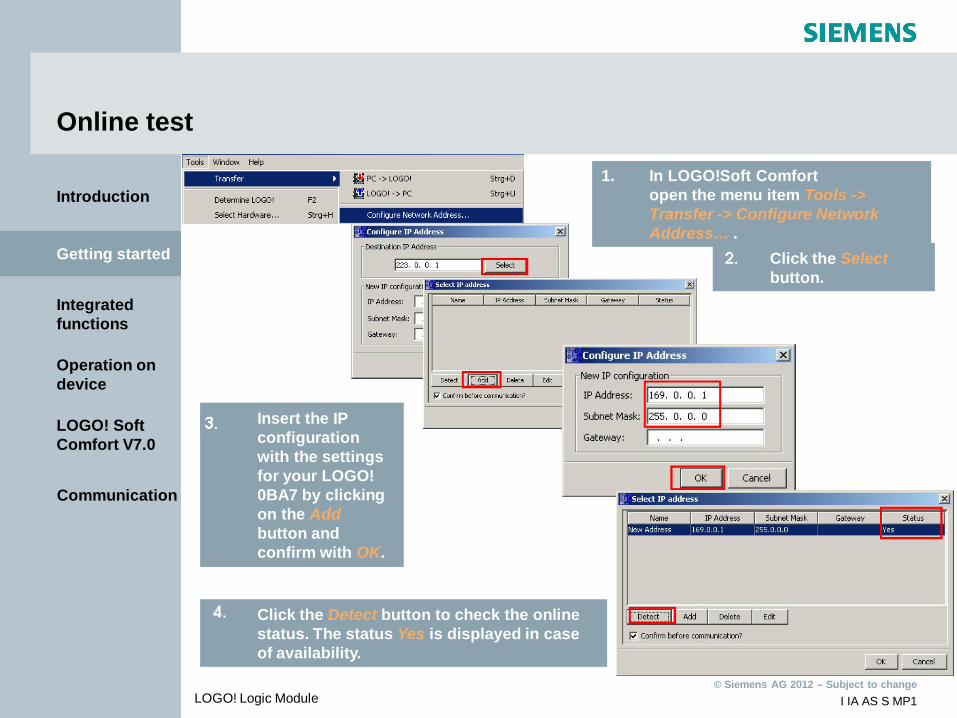
1. In LOGO!Soft Comfortopen the menu item Tools -> Transfer -> Configure Network Address… .
1. Click the Detect button to check the online status. The status Yes is displayed in case of availability.
1. Click the Selectbutton.
1. Insert the IP configuration with the settings for your LOGO! 0BA7 by clicking on the Addbutton and confirm with OK.
Getting started
Introduction
Getting started
Integrated functions
Operation on device
LOGO! Soft Comfort V7.0
Communication
I IA AS S MP1© Siemens AG 2012 – Subject to change
LOGO! Logic Module
Constants/Network - Overview
Integrated functions
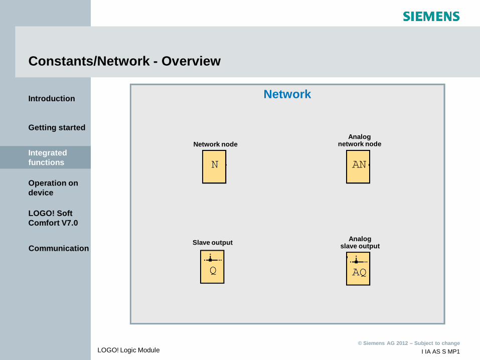
Network
Network node
Slave output
Analognetwork node
Analogslave output
Introduction
Getting started
Integrated functions
Operation on device
LOGO! Soft Comfort V7.0
Communication
I IA AS S MP1© Siemens AG 2012 – Subject to change
LOGO! Logic Module
Network – Network node
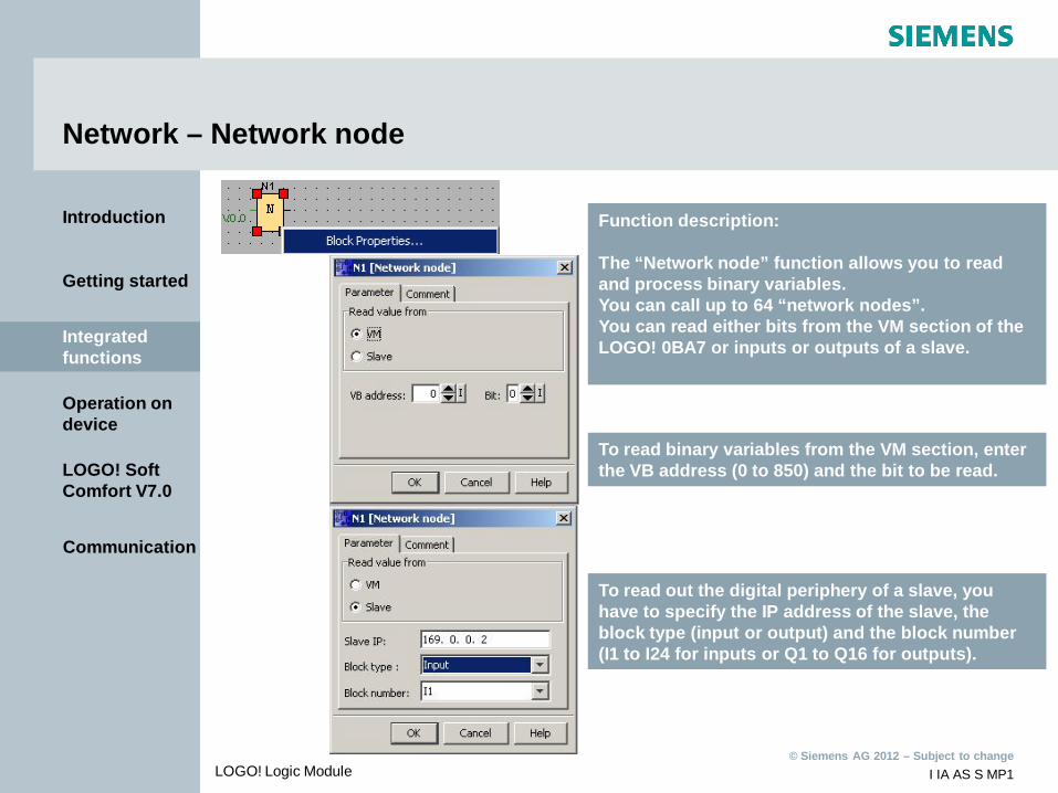
Function description:
The “Network node” function allows you to read and process binary variables.You can call up to 64 “network nodes”.You can read either bits from the VM section of the LOGO! 0BA7 or inputs or outputs of a slave.
To read binary variables from the VM section, enter the VB address (0 to 850) and the bit to be read.
To read out the digital periphery of a slave, you have to specify the IP address of the slave, the block type (input or output) and the block number (I1 to I24 for inputs or Q1 to Q16 for outputs).
Integrated functions
Introduction
Getting started
Integrated functions
Operation on device
LOGO! Soft Comfort V7.0
Communication
I IA AS S MP1© Siemens AG 2012 – Subject to change
LOGO! Logic Module
Network – Analog network node
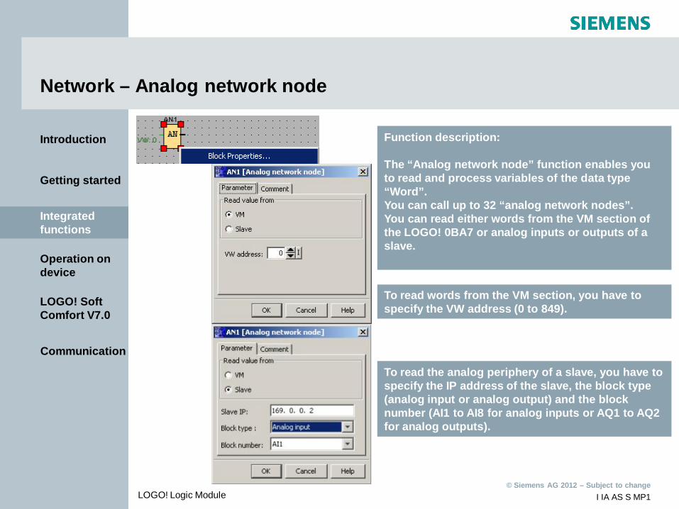
Function description:
The “Analog network node” function enables you to read and process variables of the data type “Word”.You can call up to 32 “analog network nodes”.You can read either words from the VM section of the LOGO! 0BA7 or analog inputs or outputs of a slave.
To read words from the VM section, you have to specify the VW address (0 to 849).
To read the analog periphery of a slave, you have to specify the IP address of the slave, the block type (analog input or analog output) and the block number (AI1 to AI8 for analog inputs or AQ1 to AQ2 for analog outputs).
Integrated functions
Introduction
Getting started
Integrated functions
Operation on device
LOGO! Soft Comfort V7.0
Communication
I IA AS S MP1© Siemens AG 2012 – Subject to change
LOGO! Logic Module
Network – Slave output / Analog slave output
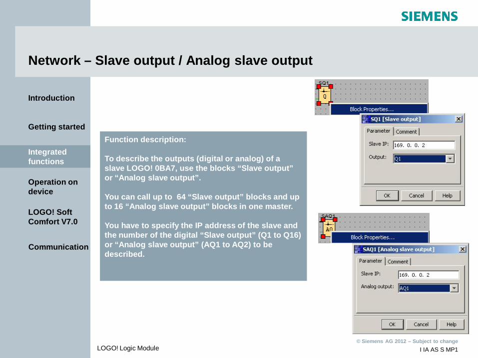
Function description:
To describe the outputs (digital or analog) of a slave LOGO! 0BA7, use the blocks “Slave output” or “Analog slave output”.
You can call up to 64 “Slave output” blocks and up to 16 “Analog slave output” blocks in one master.
You have to specify the IP address of the slave and the number of the digital “Slave output” (Q1 to Q16) or “Analog slave output” (AQ1 to AQ2) to be described.
Integrated functions
Introduction
Getting started
Integrated functions
Operation on device
LOGO! Soft Comfort V7.0
Communication
I IA AS S MP1© Siemens AG 2012 – Subject to change
LOGO! Logic Module
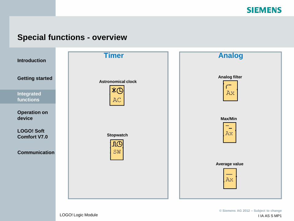
Timer
Special functions - overview
Analog
Astronomical clock
Stopwatch
Analog filter
Max/Min
Average value
Integrated functions
Introduction
Getting started
Integrated functions
Operation on device
LOGO! Soft Comfort V7.0
Communication
I IA AS S MP1© Siemens AG 2012 – Subject to change
LOGO! Logic Module
Timer – Astronomical clock
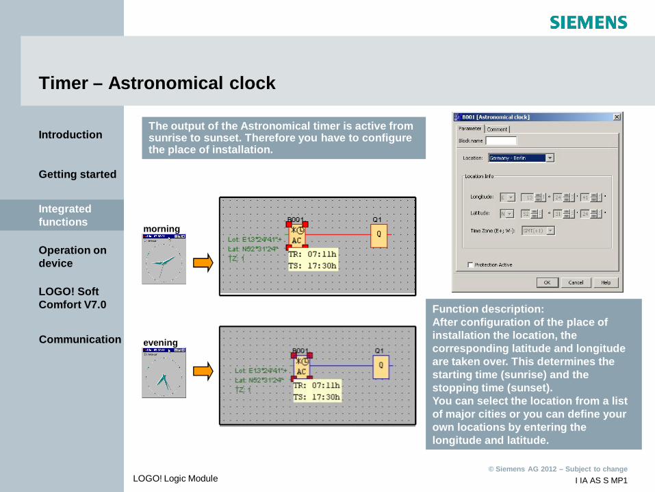
The output of the Astronomical timer is active from sunrise to sunset. Therefore you have to configure the place of installation.
Function description:After configuration of the place of installation the location, the corresponding latitude and longitude are taken over. This determines the starting time (sunrise) and the stopping time (sunset).You can select the location from a list of major cities or you can define your own locations by entering the longitude and latitude.
morning
evening
Integrated functions
Introduction
Getting started
Integrated functions
Operation on device
LOGO! Soft Comfort V7.0
Communication
I IA AS S MP1© Siemens AG 2012 – Subject to change
LOGO! Logic Module
Timer – Stopwatch
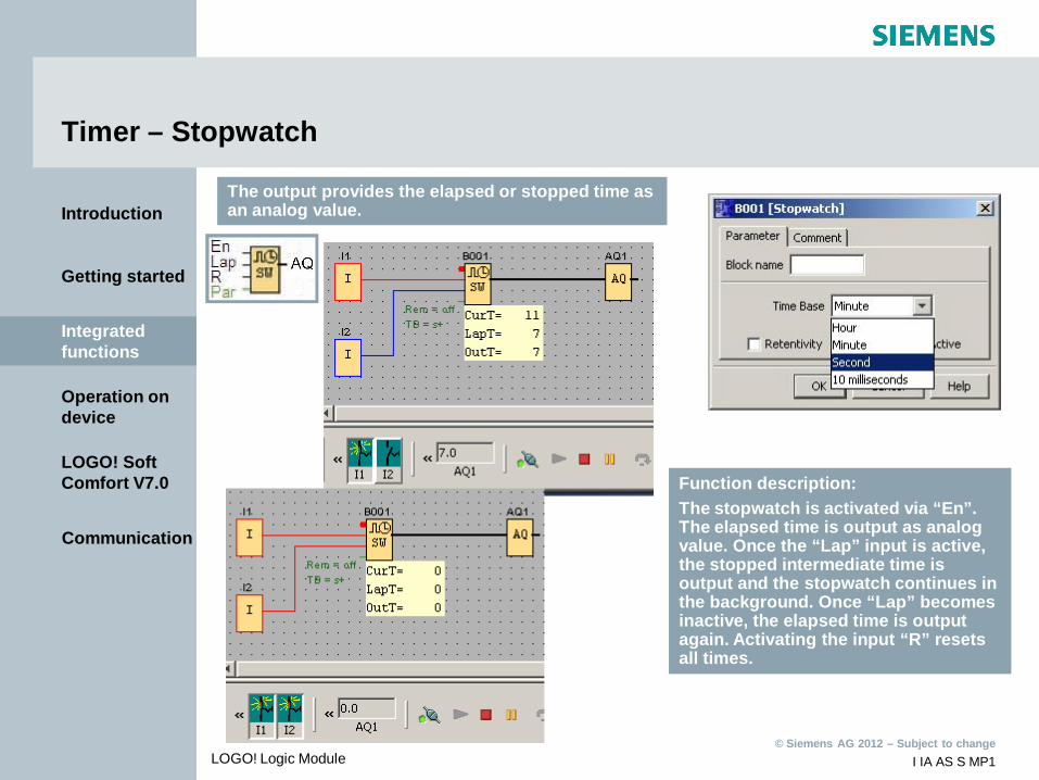
The output provides the elapsed or stopped time as an analog value.
Function description:The stopwatch is activated via “En”. The elapsed time is output as analog value. Once the “Lap” input is active, the stopped intermediate time is output and the stopwatch continues in the background. Once “Lap” becomes inactive, the elapsed time is output again. Activating the input “R” resets all times.
Integrated functions
Introduction
Getting started
Integrated functions
Operation on device
LOGO! Soft Comfort V7.0
Communication
I IA AS S MP1© Siemens AG 2012 – Subject to change
LOGO! Logic Module
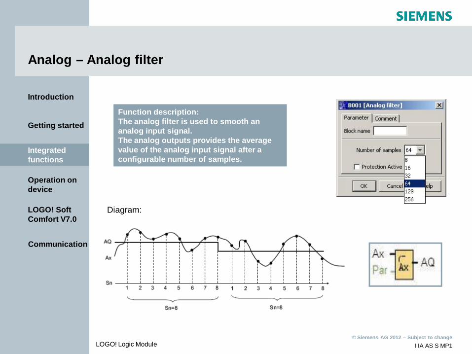
Analog – Analog filter
Function description:The analog filter is used to smooth an analog input signal. The analog outputs provides the average value of the analog input signal after a configurable number of samples.
Diagram:
Integrated functions
Introduction
Getting started
Integrated functions
Operation on device
LOGO! Soft Comfort V7.0
Communication
I IA AS S MP1© Siemens AG 2012 – Subject to change
LOGO! Logic Module
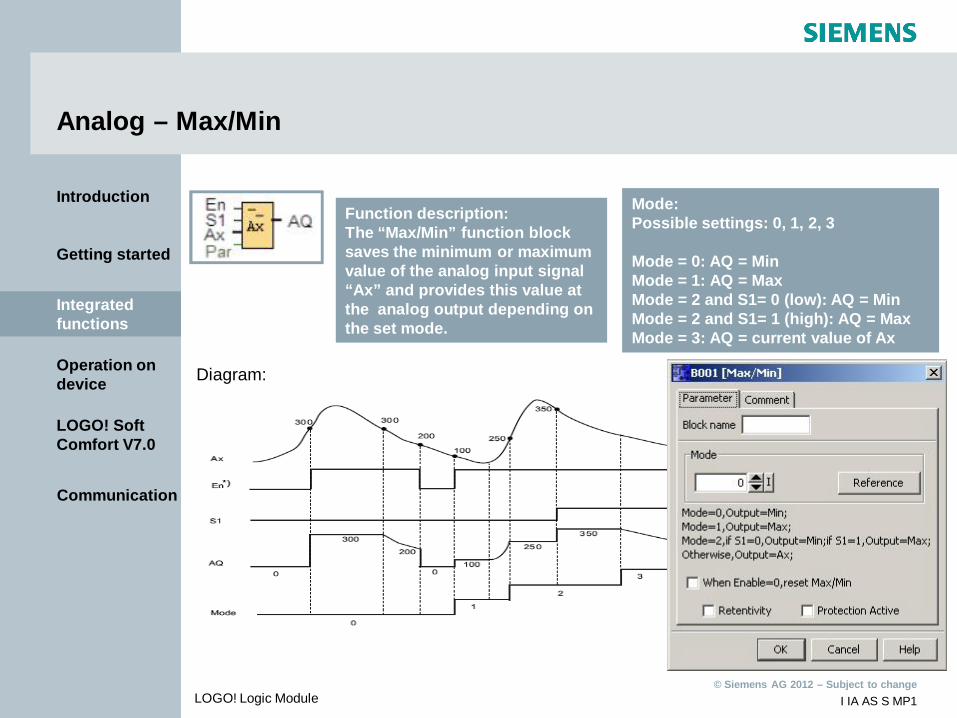
Function description:The “Max/Min” function block saves the minimum or maximum value of the analog input signal “Ax” and provides this value at the analog output depending on the set mode.
Diagram:
Mode:Possible settings: 0, 1, 2, 3
Mode = 0: AQ = MinMode = 1: AQ = MaxMode = 2 and S1= 0 (low): AQ = MinMode = 2 and S1= 1 (high): AQ = MaxMode = 3: AQ = current value of Ax
Analog – Max/Min
Integrated functions
Introduction
Getting started
Integrated functions
Operation on device
LOGO! Soft Comfort V7.0
Communication
I IA AS S MP1© Siemens AG 2012 – Subject to change
LOGO! Logic Module
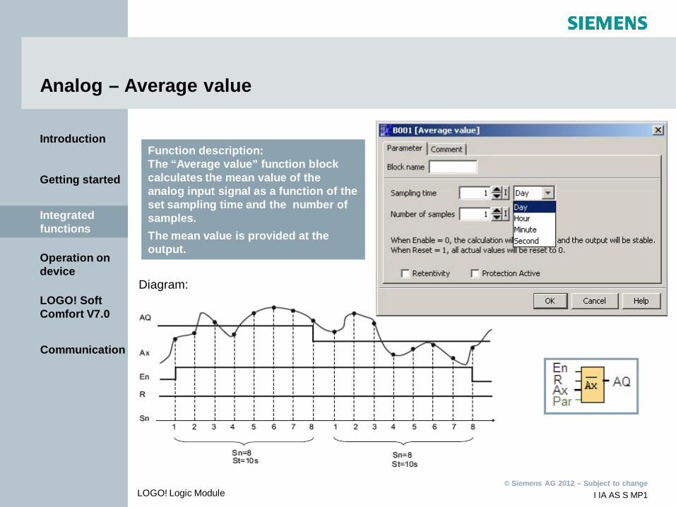
Analog – Average value
Function description:The “Average value” function block calculates the mean value of the analog input signal as a function of the set sampling time and the number of samples.The mean value is provided at the output.
Diagram:
Integrated functions
Introduction
Getting started
Integrated functions
Operation on device
LOGO! Soft Comfort V7.0
Communication
I IA AS S MP1© Siemens AG 2012 – Subject to change
LOGO! Logic Module
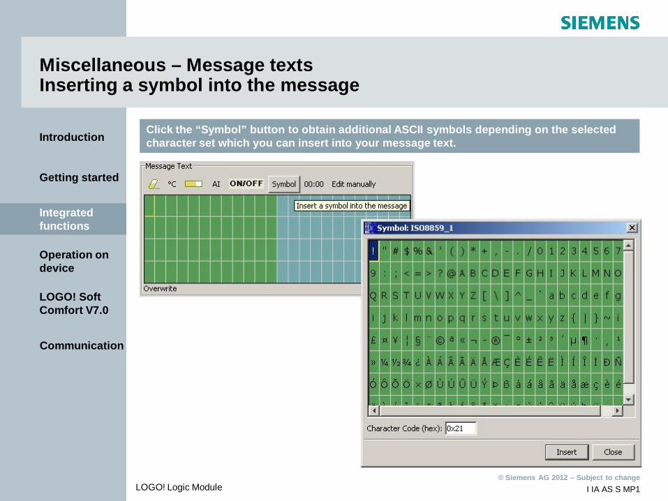
Miscellaneous – Message texts Inserting a symbol into the message
Click the “Symbol” button to obtain additional ASCII symbols depending on the selected character set which you can insert into your message text.
Integrated functions
Introduction
Getting started
Integrated functions
Operation on device
LOGO! Soft Comfort V7.0
Communication
I IA AS S MP1© Siemens AG 2012 – Subject to change
LOGO! Logic Module
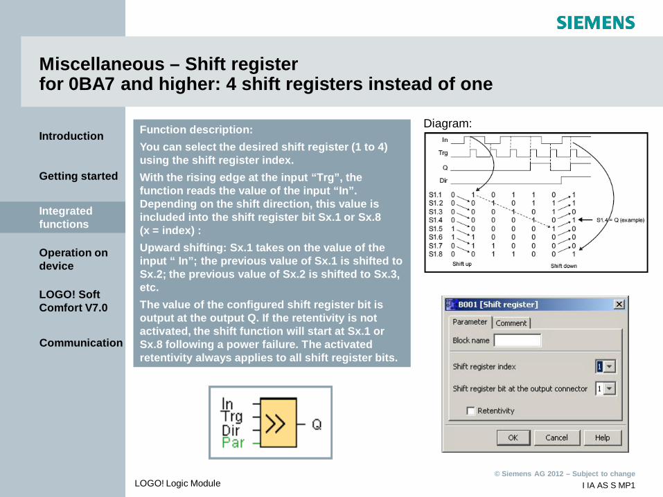
Miscellaneous – Shift registerfor 0BA7 and higher: 4 shift registers instead of one
Function description:You can select the desired shift register (1 to 4) using the shift register index.With the rising edge at the input “Trg”, the function reads the value of the input “In”. Depending on the shift direction, this value is included into the shift register bit Sx.1 or Sx.8 (x = index) :Upward shifting: Sx.1 takes on the value of the input “ In”; the previous value of Sx.1 is shifted to Sx.2; the previous value of Sx.2 is shifted to Sx.3, etc.The value of the configured shift register bit is output at the output Q. If the retentivity is not activated, the shift function will start at Sx.1 or Sx.8 following a power failure. The activated retentivity always applies to all shift register bits.
Diagram:
Integrated functions
Introduction
Getting started
Integrated functions
Operation on device
LOGO! Soft Comfort V7.0
Communication
I IA AS S MP1© Siemens AG 2012 – Subject to change
LOGO! Logic Module
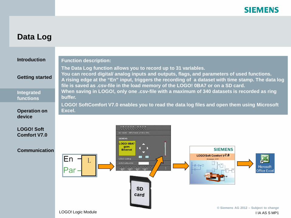
Data Log
Function description:The Data Log function allows you to record up to 31 variables.You can record digital/ analog inputs and outputs, flags, and parameters of used functions.A rising edge at the “En” input, triggers the recording of a dataset with time stamp. The data log file is saved as .csv-file in the load memory of the LOGO! 0BA7 or on a SD card. When saving in LOGO!, only one .csv-file with a maximum of 340 datasets is recorded as ring buffer. LOGO! SoftComfort V7.0 enables you to read the data log files and open them using Microsoft Excel.
Integrated functions
Introduction
Getting started
Integrated functions
Operation on device
LOGO! Soft Comfort V7.0
Communication
I IA AS S MP1© Siemens AG 2012 – Subject to change
LOGO! Logic Module
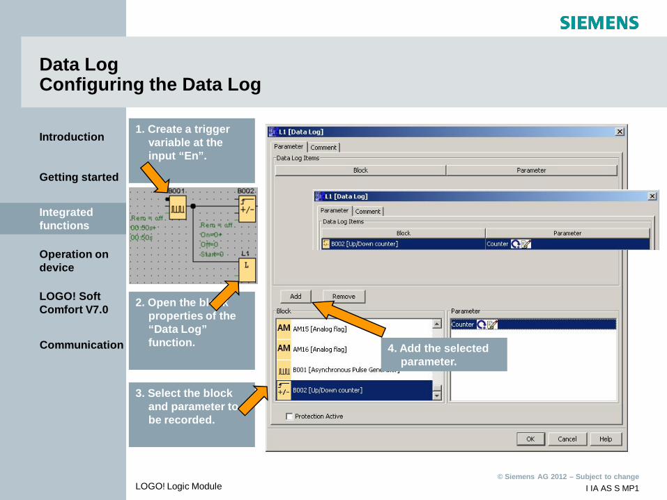
Data LogConfiguring the Data Log
1. Create a trigger variable at the input “En”.
2. Open the block properties of the “Data Log” function.
3. Select the block and parameter to be recorded.
4. Add the selected parameter.
Integrated functions
Introduction
Getting started
Integrated functions
Operation on device
LOGO! Soft Comfort V7.0
Communication
I IA AS S MP1© Siemens AG 2012 – Subject to change
LOGO! Logic Module
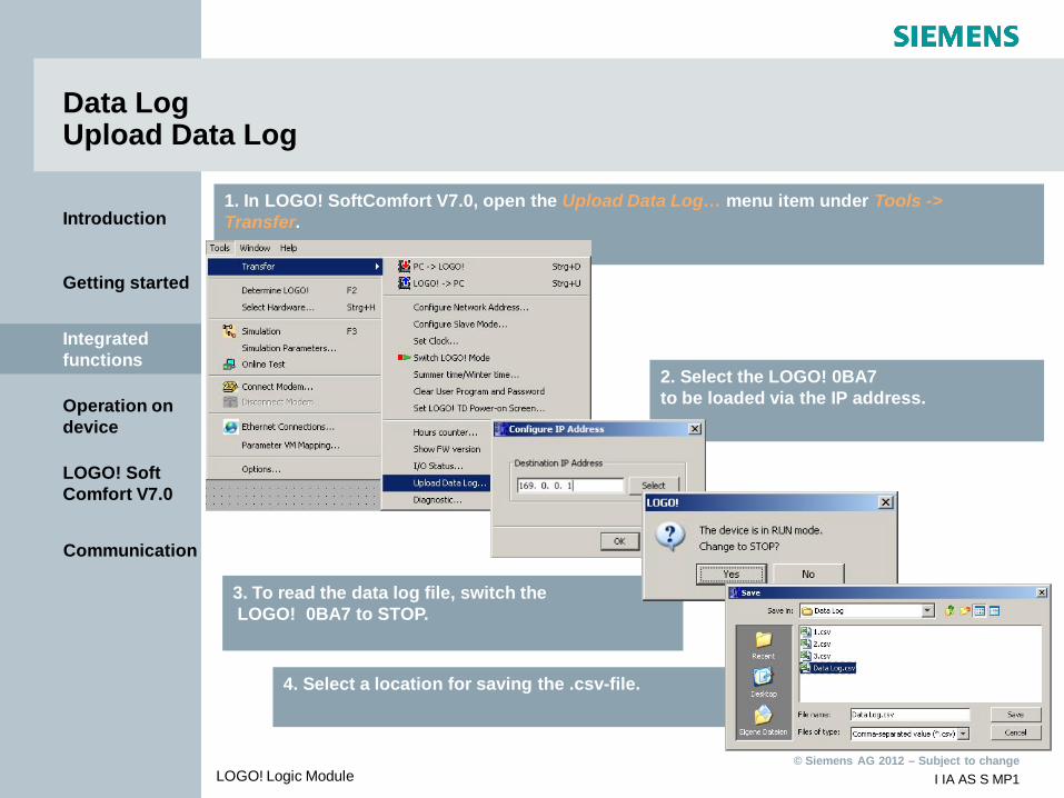
4. Select a location for saving the .csv-file.
Data LogUpload Data Log
1. In LOGO! SoftComfort V7.0, open the Upload Data Log… menu item under Tools ->Transfer.
2. Select the LOGO! 0BA7to be loaded via the IP address.
3. To read the data log file, switch theLOGO! 0BA7 to STOP.
Integrated functions
Introduction
Getting started
Integrated functions
Operation on device
LOGO! Soft Comfort V7.0
Communication
I IA AS S MP1© Siemens AG 2012 – Subject to change
LOGO! Logic Module
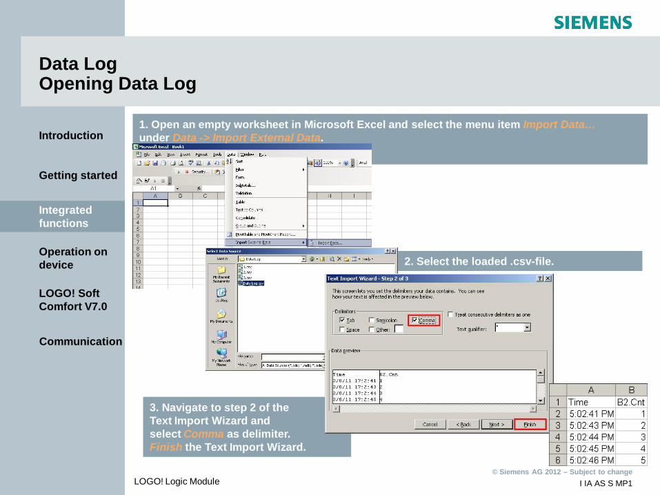
Data LogOpening Data Log
1. Open an empty worksheet in Microsoft Excel and select the menu item Import Data…under Data -> Import External Data.
2. Select the loaded .csv-file.
3. Navigate to step 2 of the Text Import Wizard and select Comma as delimiter.Finish the Text Import Wizard.
Integrated functions
Introduction
Getting started
Integrated functions
Operation on device
LOGO! Soft Comfort V7.0
Communication
I IA AS S MP1© Siemens AG 2012 – Subject to change
LOGO! Logic Module
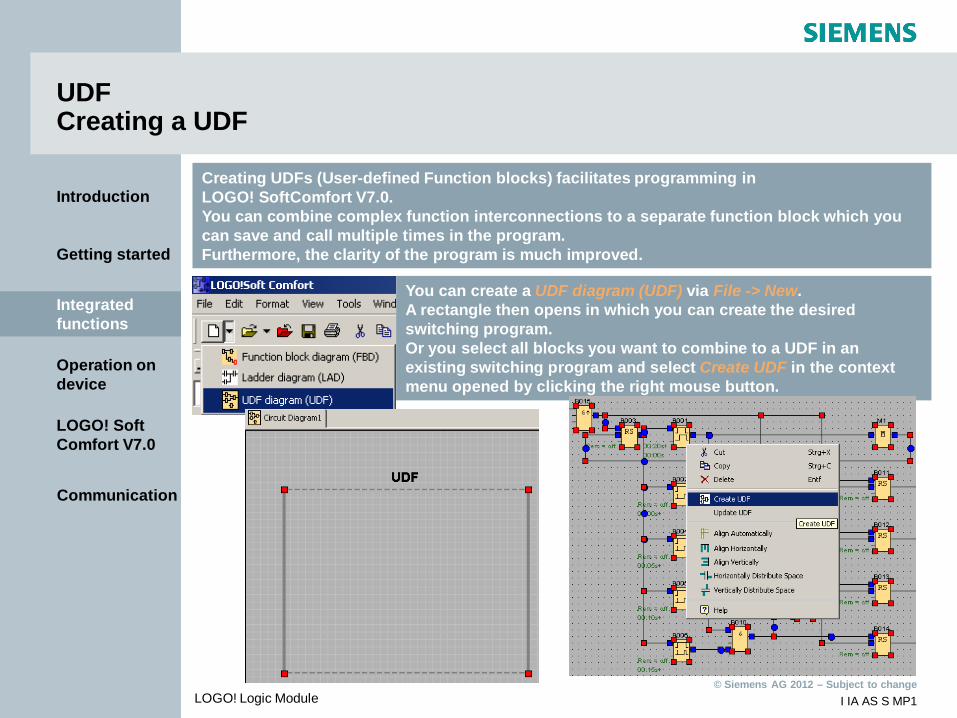
UDFCreating a UDF
You can create a UDF diagram (UDF) via File -> New.A rectangle then opens in which you can create the desired switching program.Or you select all blocks you want to combine to a UDF in an existing switching program and select Create UDF in the context menu opened by clicking the right mouse button.
Creating UDFs (User-defined Function blocks) facilitates programming inLOGO! SoftComfort V7.0.You can combine complex function interconnections to a separate function block which you can save and call multiple times in the program.Furthermore, the clarity of the program is much improved.
Integrated functions
Introduction
Getting started
Integrated functions
Operation on device
LOGO! Soft Comfort V7.0
Communication
I IA AS S MP1© Siemens AG 2012 – Subject to change
LOGO! Logic Module
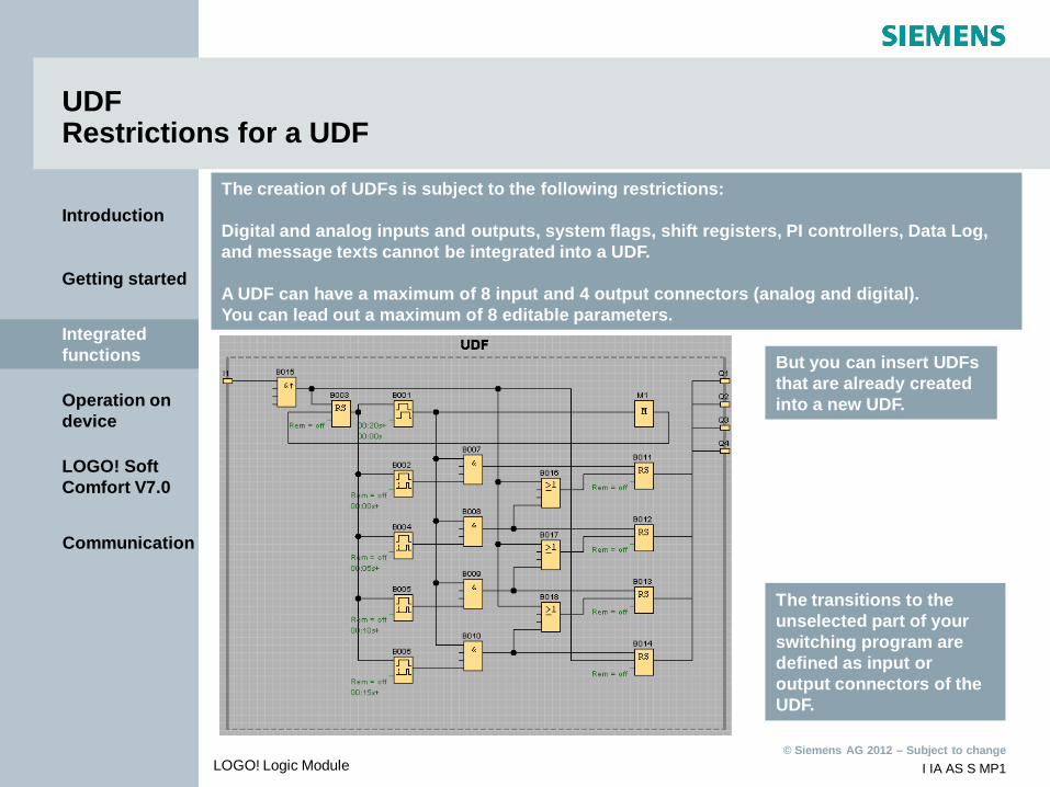
UDFRestrictions for a UDF
But you can insert UDFs that are already created into a new UDF.
The creation of UDFs is subject to the following restrictions:
Digital and analog inputs and outputs, system flags, shift registers, PI controllers, Data Log,and message texts cannot be integrated into a UDF.
A UDF can have a maximum of 8 input and 4 output connectors (analog and digital).You can lead out a maximum of 8 editable parameters.
The transitions to the unselected part of your switching program are defined as input oroutput connectors of the UDF.
Integrated functions
Introduction
Getting started
Integrated functions
Operation on device
LOGO! Soft Comfort V7.0
Communication
I IA AS S MP1© Siemens AG 2012 – Subject to change
LOGO! Logic Module
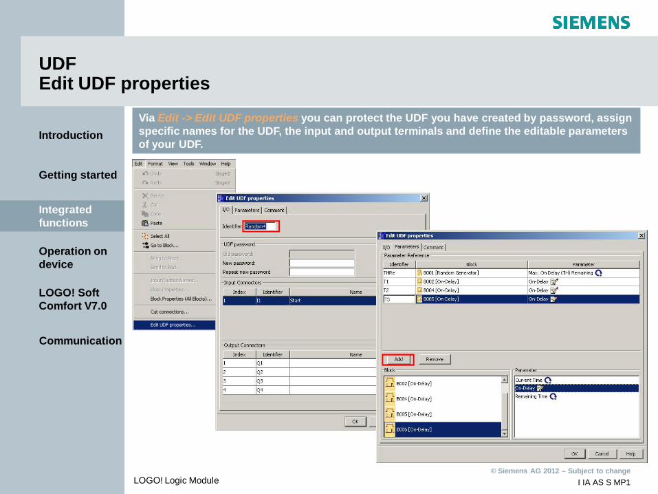
UDFEdit UDF properties
Via Edit -> Edit UDF properties you can protect the UDF you have created by password, assign specific names for the UDF, the input and output terminals and define the editable parameters of your UDF.
Integrated functions
Introduction
Getting started
Integrated functions
Operation on device
LOGO! Soft Comfort V7.0
Communication
I IA AS S MP1© Siemens AG 2012 – Subject to change
LOGO! Logic Module
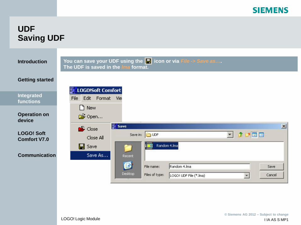
UDFSaving UDF
You can save your UDF using the icon or via File -> Save as….The UDF is saved in the lma format.
Integrated functions
Introduction
Getting started
Integrated functions
Operation on device
LOGO! Soft Comfort V7.0
Communication
I IA AS S MP1© Siemens AG 2012 – Subject to change
LOGO! Logic Module
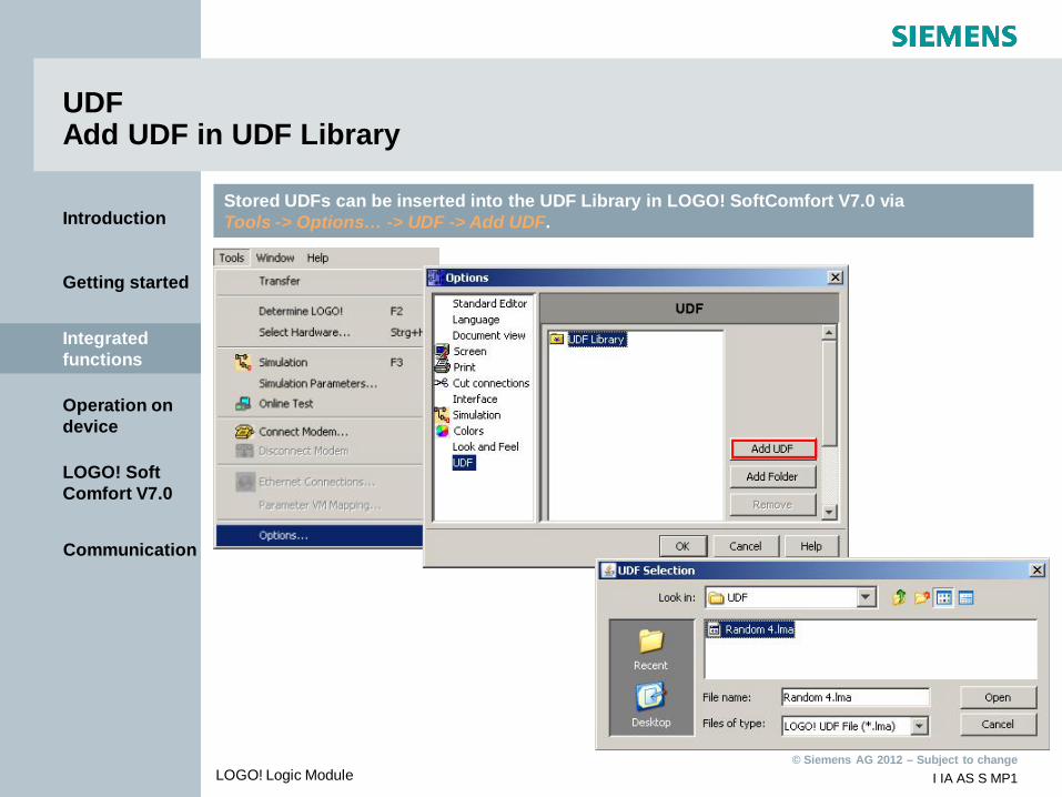
UDFAdd UDF in UDF Library
Stored UDFs can be inserted into the UDF Library in LOGO! SoftComfort V7.0 via Tools -> Options… -> UDF -> Add UDF.
Integrated functions
Introduction
Getting started
Integrated functions
Operation on device
LOGO! Soft Comfort V7.0
Communication
I IA AS S MP1© Siemens AG 2012 – Subject to change
LOGO! Logic Module
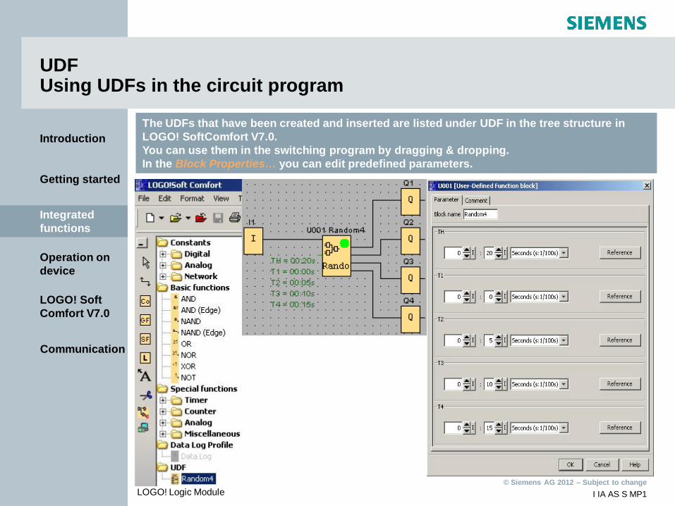
UDFUsing UDFs in the circuit program
Integrated functions
The UDFs that have been created and inserted are listed under UDF in the tree structure in LOGO! SoftComfort V7.0.You can use them in the switching program by dragging & dropping.In the Block Properties… you can edit predefined parameters.
Introduction
Getting started
Integrated functions
Operation on device
LOGO! Soft Comfort V7.0
Communication
I IA AS S MP1© Siemens AG 2012 – Subject to change
LOGO! Logic Module
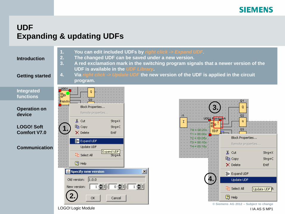
UDFExpanding & updating UDFs
Integrated functions
1. You can edit included UDFs by right click -> Expand UDF.2. The changed UDF can be saved under a new version.3. A red exclamation mark in the switching program signals that a newer version of the
UDF is available in the UDF Library.4. Via right click -> Update UDF the new version of the UDF is applied in the circuit
program.
1.
2.
3.
4.

Introduction
Getting started
Integrated functions
Operation on device
LOGO! Soft Comfort V7.0
Communication
I IA AS S MP1© Siemens AG 2012 – Subject to change
LOGO! Logic Module
LOGO! ..0BA7 – Start screen options
LOGO! 0BA7 and the ES7 version of the LOGO! TD provides the additional start screen option defaults to the parameter assignment menu.
LOGO!
Mo 09:30
2011-03-07
s
OKESC
LOGO!
StopSet Param
>Set ..Prg Name
s
OKESCOperation on device
LOGO!
Clock ..Contrast
>StartScreen
s
OKESC
LOGO!
ClockInput DI
>Menu *
s
OKESC
LOGO!
I :0.. 1234567891..01234567892..01234
s
OKESC
LOGO!
>StopSet ParamSet ..Prg Name
s
OKESC
Introduction
Getting started
Integrated functions
Operation on device
LOGO! Soft Comfort V7.0
Communication
I IA AS S MP1© Siemens AG 2012 – Subject to change
LOGO! Logic Module
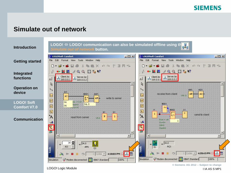
Simulate out of network
LOGO! LOGO! communication can also be simulated offline using the Simulate out of network button.
LOGO! Soft Comfort V7.0
Introduction
Getting started
Integrated functions
Operation on device
LOGO! Soft Comfort V7.0
Communication
I IA AS S MP1© Siemens AG 2012 – Subject to change
LOGO! Logic Module
Data Table
LOGO! Soft Comfort V7.0
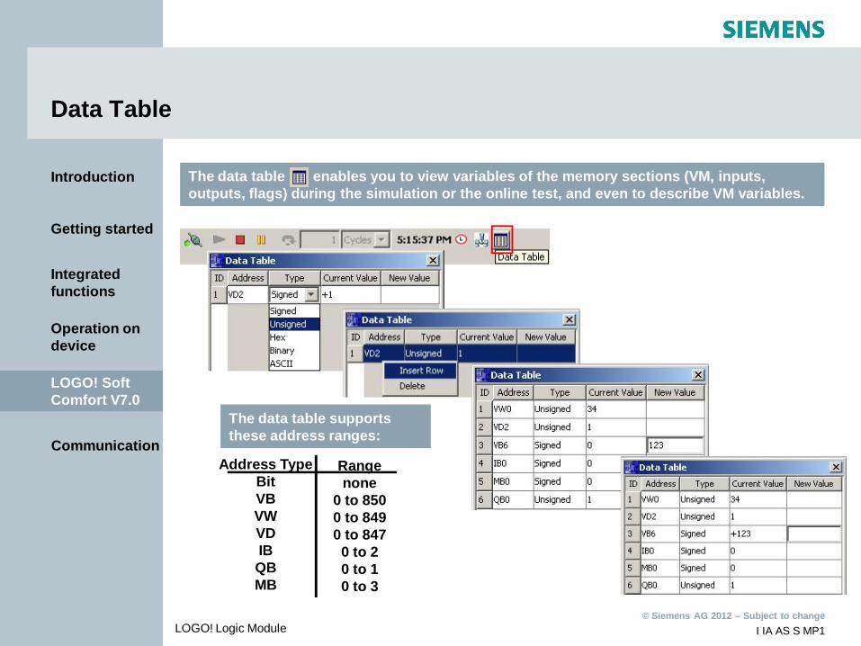
The data table enables you to view variables of the memory sections (VM, inputs, outputs, flags) during the simulation or the online test, and even to describe VM variables.
The data table supports these address ranges:
Address TypeBitVBVWVDIBQBMB
Rangenone
0 to 8500 to 8490 to 847
0 to 20 to 10 to 3
Introduction
Getting started
Integrated functions
Operation on device
LOGO! Soft Comfort V7.0
Communication
I IA AS S MP1© Siemens AG 2012 – Subject to change
LOGO! Logic Module
I/O Status Overview
LOGO! Soft Comfort V7.0
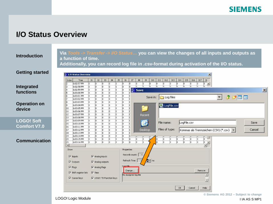
Via Tools -> Transfer -> I/O Status… you can view the changes of all inputs and outputs as a function of time.Additionally, you can record log file in .csv-format during activation of the I/O status.
Introduction
Getting started
Integrated functions
Operation on device
LOGO! Soft Comfort V7.0
Communication
I IA AS S MP1© Siemens AG 2012 – Subject to change
LOGO! Logic Module
Diagnostic
LOGO! Soft Comfort V7.0
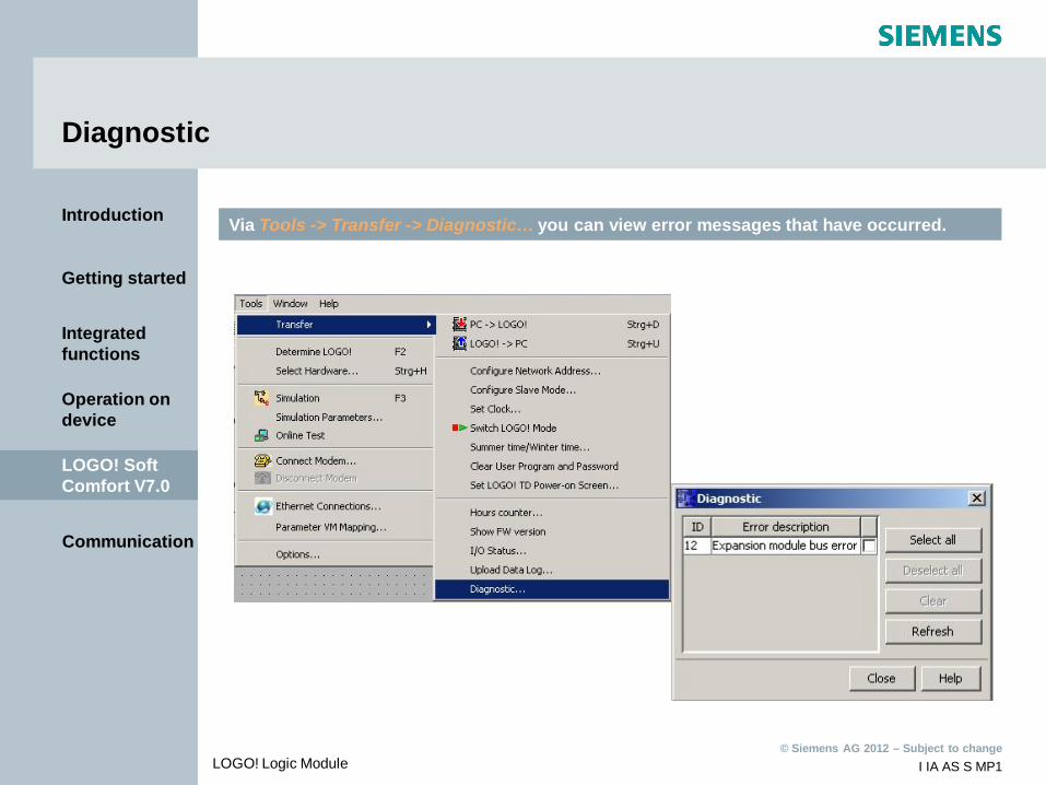
Via Tools -> Transfer -> Diagnostic… you can view error messages that have occurred.
Introduction
Getting started
Integrated functions
Operation on device
LOGO! Soft Comfort V7.0
Communication
I IA AS S MP1© Siemens AG 2012 – Subject to change
LOGO! Logic Module
LOGO! LOGO! communication (master – slave)
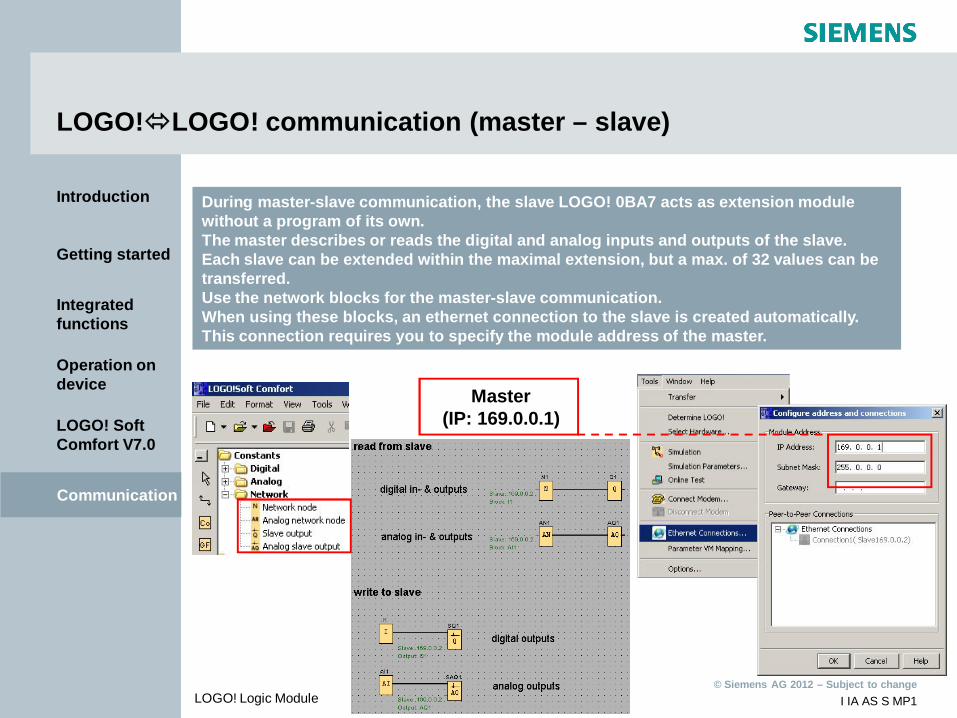
During master-slave communication, the slave LOGO! 0BA7 acts as extension module without a program of its own.The master describes or reads the digital and analog inputs and outputs of the slave.Each slave can be extended within the maximal extension, but a max. of 32 values can be transferred.Use the network blocks for the master-slave communication.When using these blocks, an ethernet connection to the slave is created automatically.This connection requires you to specify the module address of the master.
Master(IP: 169.0.0.1)
Communication
Introduction
Getting started
Integrated functions
Operation on device
LOGO! Soft Comfort V7.0
Communication
I IA AS S MP1© Siemens AG 2012 – Subject to change
LOGO! Logic Module
LOGO! LOGO! communication (slave mode)
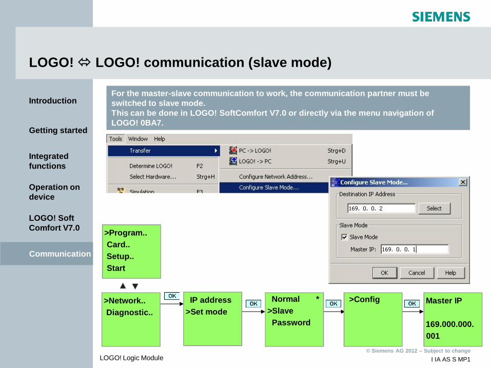
For the master-slave communication to work, the communication partner must be switched to slave mode.This can be done in LOGO! SoftComfort V7.0 or directly via the menu navigation of LOGO! 0BA7.
>Program..Card..Setup..Start
>Network..Diagnostic..
IP address>Set mode
Normal *>SlavePassword
>Config Master IP
169.000.000.001
Communication
Introduction
Getting started
Integrated functions
Operation on device
LOGO! Soft Comfort V7.0
Communication
I IA AS S MP1© Siemens AG 2012 – Subject to change
LOGO! Logic Module
LOGO! LOGO! communication (client – server)Adding a connection
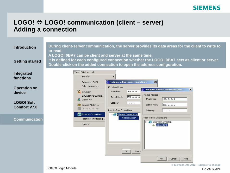
During client-server communication, the server provides its data areas for the client to write to or read.A LOGO! 0BA7 can be client and server at the same time.It is defined for each configured connection whether the LOGO! 0BA7 acts as client or server.Double-click on the added connection to open the address configuration.
Communication
Introduction
Getting started
Integrated functions
Operation on device
LOGO! Soft Comfort V7.0
Communication
I IA AS S MP1© Siemens AG 2012 – Subject to change
LOGO! Logic Module
LOGO! LOGO! communication (client – server)Configuring the connection
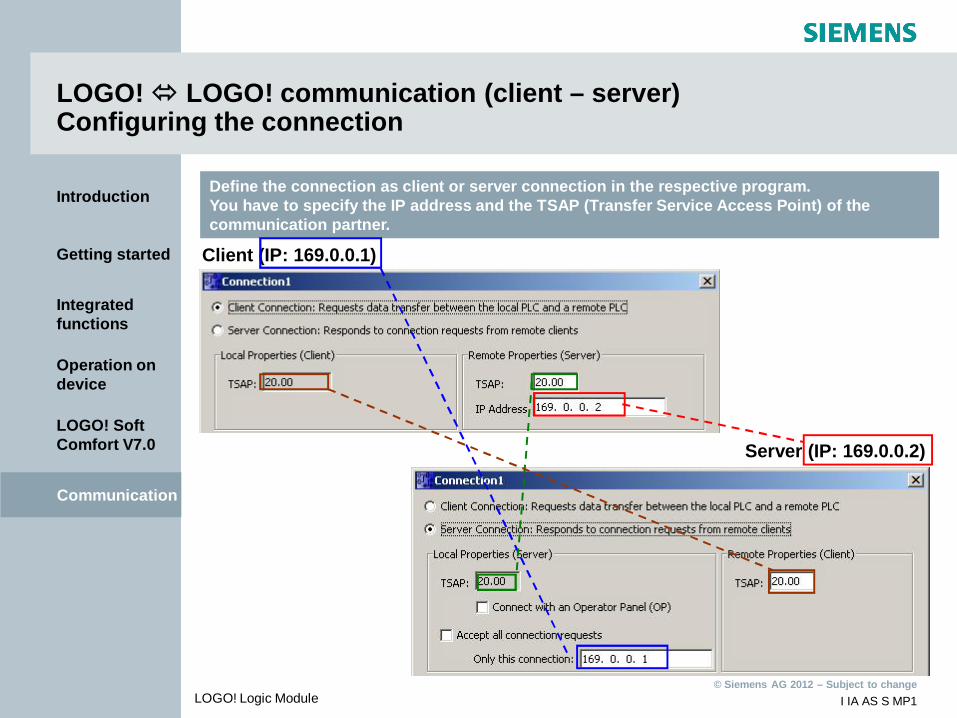
Define the connection as client or server connection in the respective program.You have to specify the IP address and the TSAP (Transfer Service Access Point) of thecommunication partner.
Client (IP: 169.0.0.1)
Server (IP: 169.0.0.2)
Communication
Introduction
Getting started
Integrated functions
Operation on device
LOGO! Soft Comfort V7.0
Communication
I IA AS S MP1© Siemens AG 2012 – Subject to change
LOGO! Logic Module
LOGO! LOGO! communication (client – server)Data transfer
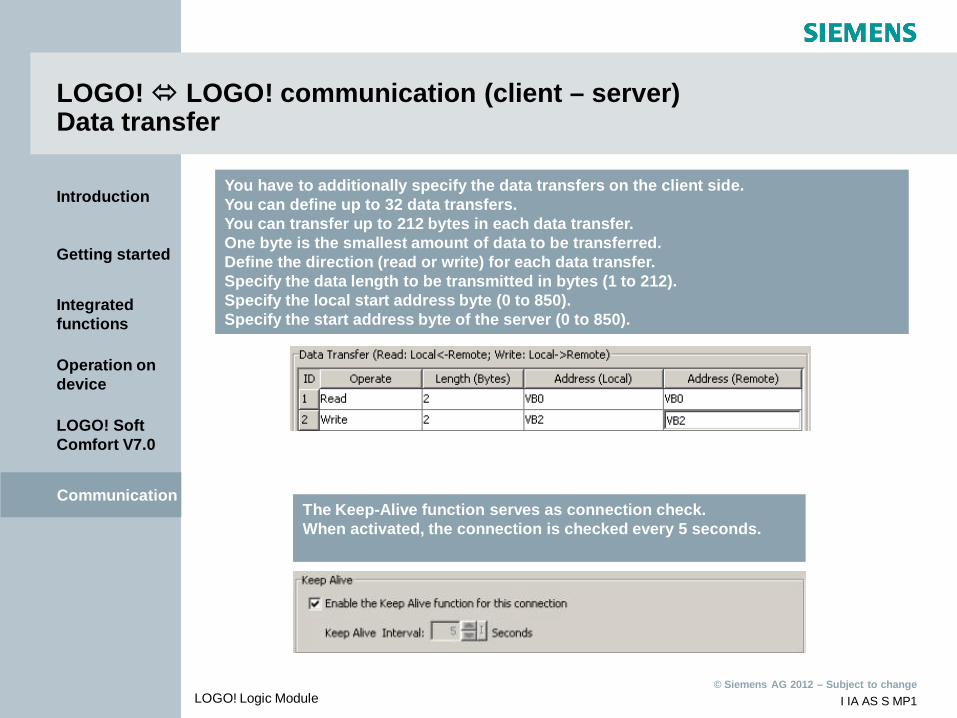
You have to additionally specify the data transfers on the client side. You can define up to 32 data transfers.You can transfer up to 212 bytes in each data transfer.One byte is the smallest amount of data to be transferred.Define the direction (read or write) for each data transfer.Specify the data length to be transmitted in bytes (1 to 212).Specify the local start address byte (0 to 850).Specify the start address byte of the server (0 to 850).
The Keep-Alive function serves as connection check.When activated, the connection is checked every 5 seconds.
Communication
Introduction
Getting started
Integrated functions
Operation on device
LOGO! Soft Comfort V7.0
Communication
I IA AS S MP1© Siemens AG 2012 – Subject to change
LOGO! Logic Module
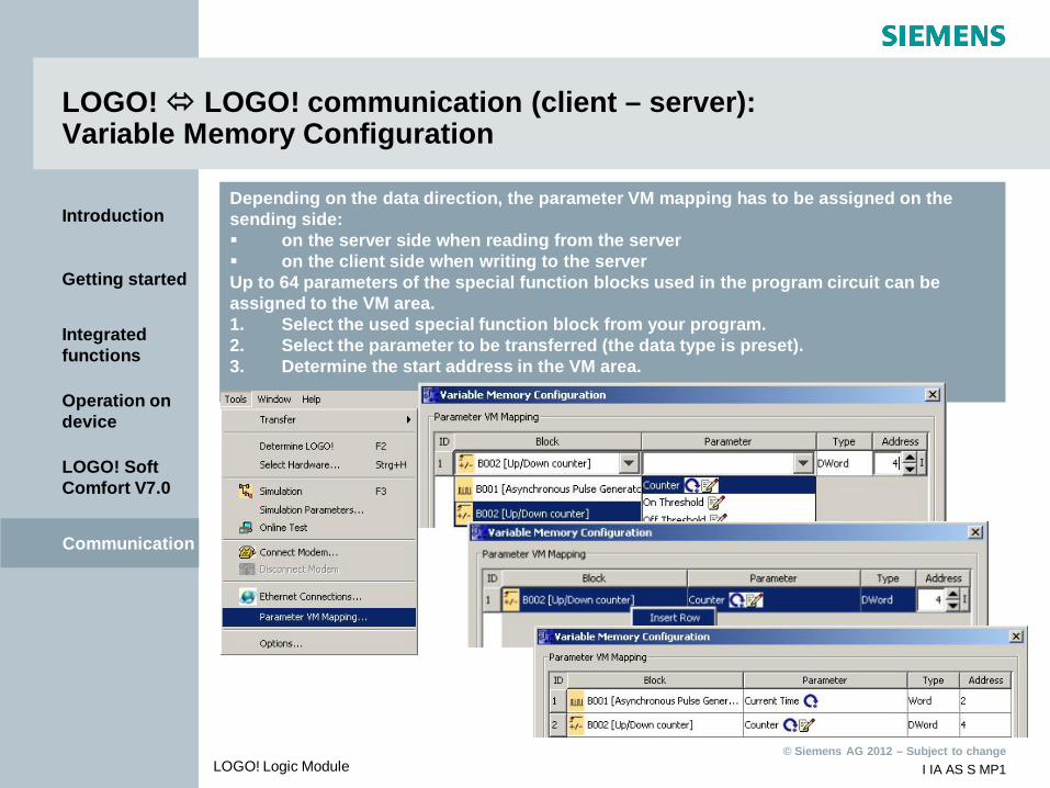
Depending on the data direction, the parameter VM mapping has to be assigned on thesending side:
on the server side when reading from the serveron the client side when writing to the server
Up to 64 parameters of the special function blocks used in the program circuit can beassigned to the VM area.1. Select the used special function block from your program.2. Select the parameter to be transferred (the data type is preset).3. Determine the start address in the VM area.
LOGO! LOGO! communication (client – server):Variable Memory Configuration
Communication
Introduction
Getting started
Integrated functions
Operation on device
LOGO! Soft Comfort V7.0
Communication
I IA AS S MP1© Siemens AG 2012 – Subject to change
LOGO! Logic Module
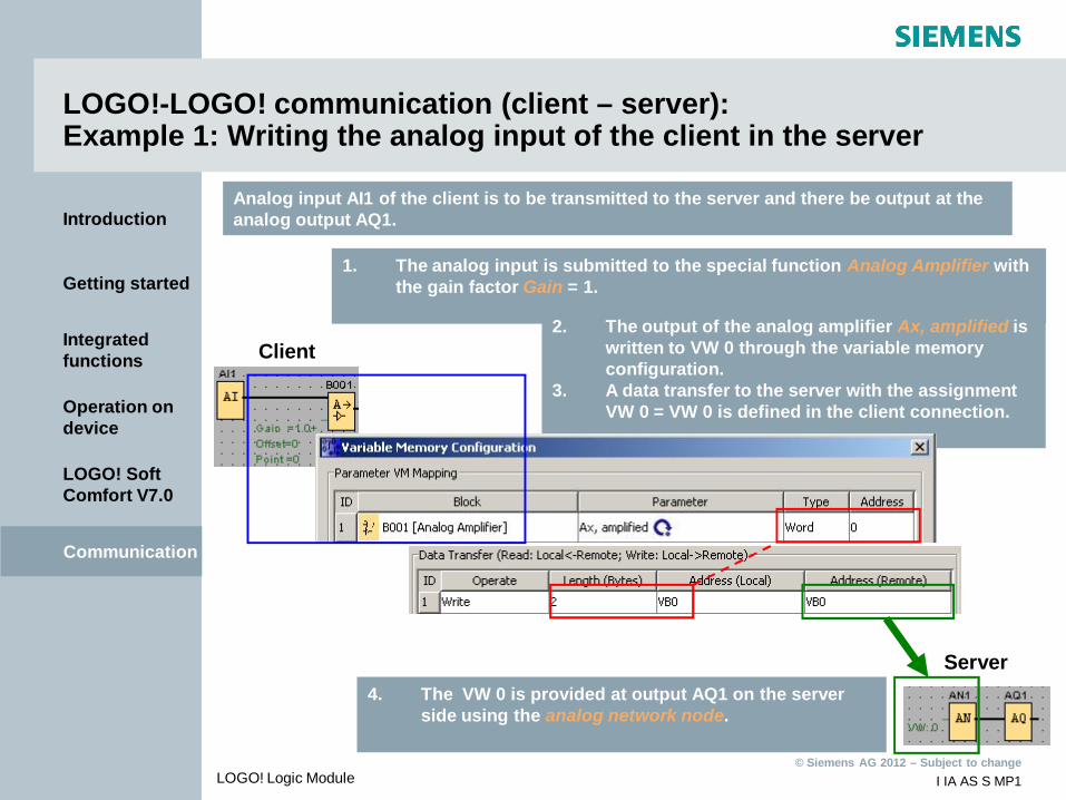
1. The analog input is submitted to the special function Analog Amplifier with the gain factor Gain = 1.
2. The output of the analog amplifier Ax, amplified is written to VW 0 through the variable memory configuration.
3. A data transfer to the server with the assignment VW 0 = VW 0 is defined in the client connection.
LOGO!-LOGO! communication (client – server):Example 1: Writing the analog input of the client in the server
Analog input AI1 of the client is to be transmitted to the server and there be output at the analog output AQ1.
Client
Server4. The VW 0 is provided at output AQ1 on the server
side using the analog network node.
Communication
Introduction
Getting started
Integrated functions
Operation on device
LOGO! Soft Comfort V7.0
Communication
I IA AS S MP1© Siemens AG 2012 – Subject to change
LOGO! Logic Module
LOGO!-LOGO! communication (client – server):Example 2: Reading a digital input from the server (1)
Communication
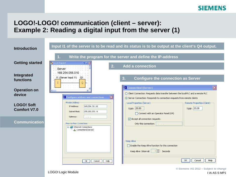
1. Write the program for the server and define the IP-address
2. Add a connection
3. Configure the connection as Server
Input I1 of the server is to be read and its status is to be output at the client‘s Q4 output.
Introduction
Getting started
Integrated functions
Operation on device
LOGO! Soft Comfort V7.0
Communication
I IA AS S MP1© Siemens AG 2012 – Subject to change
LOGO! Logic Module
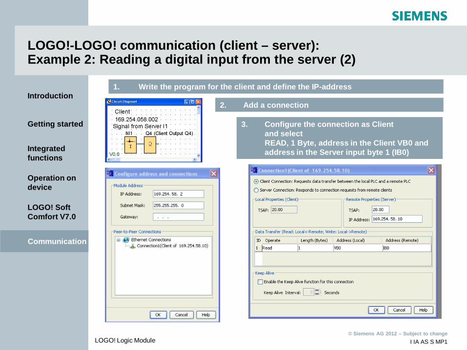
LOGO!-LOGO! communication (client – server):Example 2: Reading a digital input from the server (2)
Communication
1. Write the program for the client and define the IP-address
2. Add a connection
3. Configure the connection as Clientand select READ, 1 Byte, address in the Client VB0 and address in the Server input byte 1 (IB0)
Introduction
Getting started
Integrated functions
Operation on device
LOGO! Soft Comfort V7.0
Communication
I IA AS S MP1© Siemens AG 2012 – Subject to change
LOGO! Logic Module
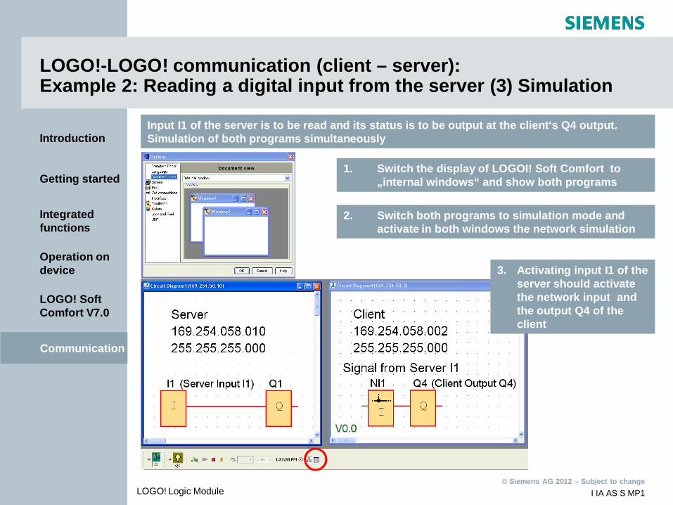
LOGO!-LOGO! communication (client – server):Example 2: Reading a digital input from the server (3) Simulation
Communication
1. Switch the display of LOGOI! Soft Comfort to „internal windows“ and show both programs
2. Switch both programs to simulation mode and activate in both windows the network simulation
Input I1 of the server is to be read and its status is to be output at the client‘s Q4 output.Simulation of both programs simultaneously
3. Activating input I1 of the server should activate the network input and the output Q4 of the client
Introduction
Getting started
Integrated functions
Operation on device
LOGO! Soft Comfort V7.0
Communication
I IA AS S MP1© Siemens AG 2012 – Subject to change
LOGO! Logic Module
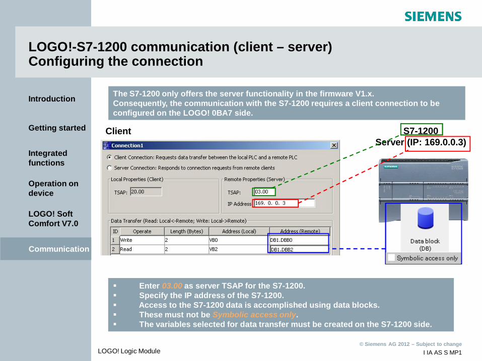
LOGO!-S7-1200 communication (client – server)Configuring the connection
The S7-1200 only offers the server functionality in the firmware V1.x.Consequently, the communication with the S7-1200 requires a client connection to be configured on the LOGO! 0BA7 side.
Client S7-1200Server (IP: 169.0.0.3)
Enter 03.00 as server TSAP for the S7-1200.Specify the IP address of the S7-1200.Access to the S7-1200 data is accomplished using data blocks.These must not be Symbolic access only.The variables selected for data transfer must be created on the S7-1200 side.
Communication
Introduction
Getting started
Integrated functions
Operation on device
LOGO! Soft Comfort V7.0
Communication
I IA AS S MP1© Siemens AG 2012 – Subject to change
LOGO! Logic Module
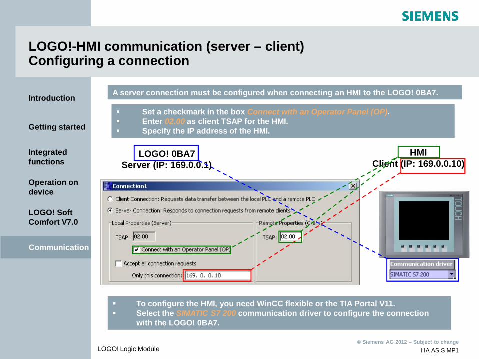
LOGO!-HMI communication (server – client)Configuring a connection
A server connection must be configured when connecting an HMI to the LOGO! 0BA7.
LOGO! 0BA7Server (IP: 169.0.0.1)
HMIClient (IP: 169.0.0.10)
To configure the HMI, you need WinCC flexible or the TIA Portal V11.Select the SIMATIC S7 200 communication driver to configure the connection with the LOGO! 0BA7.
Set a checkmark in the box Connect with an Operator Panel (OP).Enter 02.00 as client TSAP for the HMI.Specify the IP address of the HMI.
Communication