Embed Size (px)
Citation preview
Page 1
Lotus Service Notes Section FJ
TRANSMISSION
SECTION FJ
Sub-Section Page
Introduction FJ.1 2
Gearchange Mechanism FJ.2 6
Lubrication FJ.3 13
Driveshafts FJ.4 14
Transmission Replacement FJ.5 17
Transmission Overhaul & Special Tools FJ.6 18
See also Toyota transmission repair manual:
1ZZ / 2ZZ Engine - C64/C56 repair manual E120T0327J 1ZR / 2ZR Engine - EC60 repair manual CD T000T1523F
Updated 31st October 2013

Lotus Service Notes Section FJ
Page 2
FJ.1 - INTRODUCTION
The Elise S 5-speed transmission, the 2ZZ powered Elise/Exige 6-speed transmission, and the 1ZR powered Elise 6-speed, are all of similar construction, being 'end on' type, mounted on the left hand end of the engine unit, and comprising the clutch housing, gearbox, final drive gears, and differential. All units are sup-plied by Toyota, and are designated correspondingly 'C56', 'C64' and EC60 (C = series; 5 or 6 = no. of gears; 6, 4 or 0 = ratio set). Publication E120T0327J covers the repair of the C56 and C60, with CD T000T1523F covering the EC60.
Two control cables, running along the centre of the cabin and beneath the power unit, are used to transmit the movement of the gearchange lever to the transmission selector mechanism.
C56 Five Speed(reverse idler omitted Clutch housing f138
for clarity) Clutch splines 5 4 3 2 R 1
End cover(casting on Lotus) Gearbox casing
LH driveshaft inboard CV joint
Final drive output gear Bevel gear differential
Page 3
Lotus Service Notes Section FJ
NEW FEATURES – MANUAL TRANSAXLE
04F6CH15C
EC60 Manual TransaxleEC60A Multi-mode Manual Transaxle
EC65 Manual TransaxleEC65A Multi-mode Manual Transaxle
NF-150
MANUAL TRANSAXLE
JDESCRIPTION
D The EC60 and EC65 manual transaxle is 6-speed manual transaxle.
D TheEC60AandEC65AMulti-modeManual Transaxles (M-MT) are 6-speedmanual transaxles. Aclutchactuator, shift and select actuator and various sensors are added to the EC60/EC65 manual transaxle,producing the EC60A/EC65AM-MT. These actuators and sensors enable clutch operation and shift andselect�operation�to�be�controlled�by�the�system.�For�details,�see�page�NF-159.
D The following items areused to improve torque transmission efficiency andachieve anexcellent shift feel:
Improved Torque D Low friction bearings are used.Improved TorqueTransmission Efficiency
Low friction bearings are used.D Oil separators are used.
Excellent Shift Feel
D The shift mechanism is optimized.D A pre-synchronizing system is used for reverse gear.D A 2-step sleeve chamfer structure is used for transmission hub sleeve No. 2
(synchromesh mechanism for 3rd and 4th gear).D A triple-cone type synchromesh mechanism is used for 1st and 2nd gears.
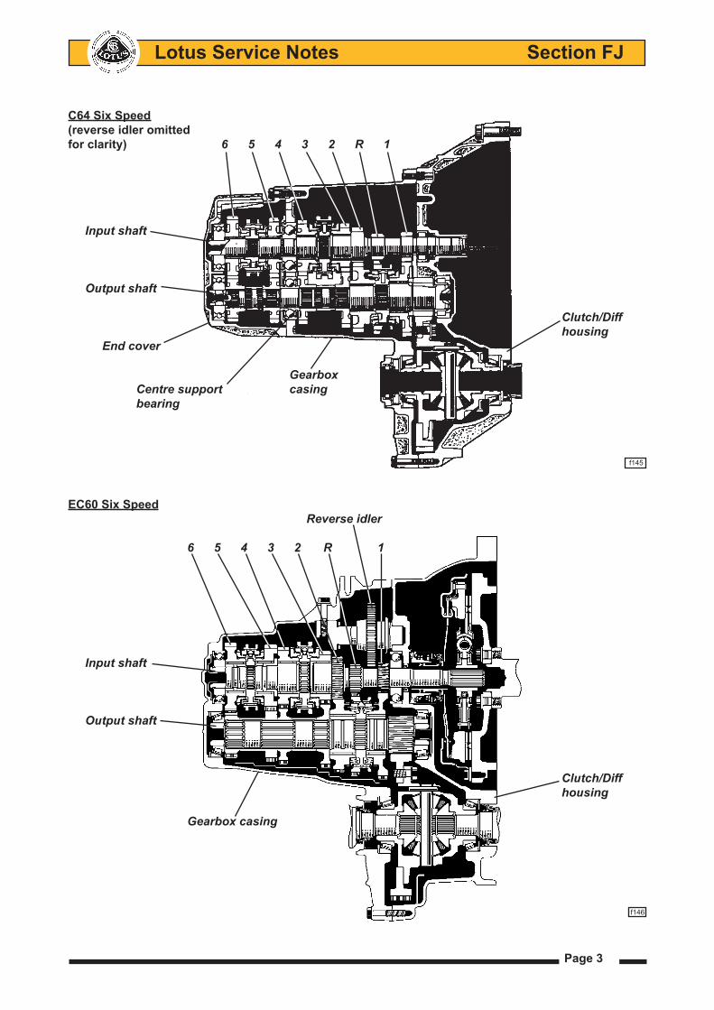
C64 Six Speed(reverse idler omittedfor clarity) 6 5 4 3 2 R 1
Input shaft
Output shaft
Clutch/Diff housing End cover
Gearbox Centre support casing bearing
f145
EC60 Six Speed Reverse idler
6 5 4 3 2 R 1
Input shaft
Output shaft
Clutch/Diff housing
Gearbox casing
f146
Page 4
Lotus Service Notes Section FJ
The two shaft, all indirect gearbox, is housed within a two or three part cast alloy casing, including the dry chamber clutch housing, and secured by threaded fasteners to the back of the engine block. The clutch friction plate is splined to the gearbox input shaft from which the power flows to the output shaft mounted below it, and thence to the final drive and differential into which are fitted the driveshafts.
In the C56 5-speed gearbox, ratios 1 to 4 including reverse, are contained within the main case, with the 5th gearset overhung at the rear within an end cover. The input shaft uses a front roller bearing and a rear ball bearing, as does the output shaft, albeit with a much larger front roller to accommodate the final drive gear forces. Needle roller bearings are used for each of the free spinning gears, and a pair of taper roller bearings support the differential assembly. Sychroniser assemblies for 3rd/4th and 5th speeds are mounted on the in-put shaft, and that for 1st/2nd on the output shaft, with the latter also providing the reverse gear driven pinion incorporated on its periphery. A reverse gear idler pinion is mounted on its own stub shaft, and may be slid into engagement with both a gear integral with the input shaft, and the ring gear on the 1st/2nd synchroniser. The housing for the final drive and differential is shared between the clutch housing and gearbox case, with taper roller bearings supporting the differential.
The C64 six-speed transmission is a development of the C56, with both shafts extended at the rear to accommodate the additional ratio. Extra ball bearings are included in the end case to support the tails of each shaft.
The EC60 6-speed transmission is a further evolution of the C64, but dispenses with the separate end casing and shaft centre support bearings, using instead, front and rear ball bearings for the input shaft, and a pair of opposed taper roller bearings for the output shaft. A reverse gear engagement aid is provided by a mechanism which applies a loading to the 6th gear synchroniser cone, to help stop input shaft rotation, before the reverse idler gear teeth are slid into engagement.
Page 5
Lotus Service Notes Section FJ
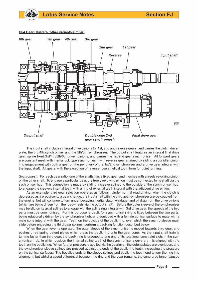
C64 Gear Clusters (other variants similar)
The input shaft includes integral drive pinions for 1st, 2nd and reverse gears, and carries the clutch driven plate, the 3rd/4th synchroniser and the 5th/6th synchroniser. The output shaft features an integral final drive gear, spline fixed 3rd/4th/5th/6th driven pinions, and carries the 1st/2nd gear synchroniser. All forward gears are constant mesh with inertia lock type synchromesh, with reverse gear attained by sliding a spur idler pinion into engagement with both a gear on the periphery of the 1st/2nd synchroniser and a drive gear integral with the input shaft. All gears, with the exception of reverse, use a helical tooth form for quiet running.
Sychromesh: For each gear ratio, one of the shafts has a fixed gear, and meshes with a freely revolving pinion on the other shaft. To engage a particular gear, the freely revolving pinion must be connected to its shaft via the sychroniser hub. This connection is made by sliding a sleeve splined to the outside of the synchroniser hub, to engage the sleeve's internal teeth with a ring of external teeth integral with the adjacent drive pinion.
As an example, third gear selection operates as follows: Under normal road driving, when the clutch is depressed as a precurser to a gear change, the input shaft with the third gear synchroniser are de-coupled from the engine, but will continue to turn under decaying inertia, clutch windage, and oil drag from the drive pinions (which are being driven from the roadwheels via the output shaft). Before the outer sleeve of the synchroniser may be slid on its axial splines to engage with the spline ring integral with 3rd drive gear, the speeds of the two parts must be commonised. For this purpose, a baulk (or synchroniser) ring is fitted between the two parts, being rotationally driven by the synchroniser hub, and equipped with a female conical surface to mate with a male cone integral with the gear. Teeth on the outside of the baulk ring, over which the synchro sleeve must slide before engaging the third gear splines, perform a baulking function described below:
When the gear lever is operated, the outer sleeve of the synchroniser is moved towards third gear, and pushes three spring detent plates which press the baulk ring onto the gear cone. As the input shaft train is turning faster than third gear, the baulk ring is dragged to one end of its rotational constraint slots in the syn-chroniser hub, in which position the internal spline teeth of the synchroniser sleeve are mis-aligned with the teeth on the baulk ring. When further pressure is applied via the gearlever, the detent plates are overidden, and the synchroniser sleeve splines are pressed against the ends of the baulk ring teeth, increasing the pressure on the conical surfaces. The bevelled ends of the sleeve splines and baulk ring teeth tend to turn the ring into alignment, but whilst a speed differential between the ring and the gear remains, the cone drag force (caused
6th gear 5th gear 4th gear 3rd gear 2nd gear 1st gear
Reverse Input shaft
f130
Output shaft Double cone 2nd Final drive gear gear synchromesh
Lotus Service Notes Section FJ
Page 6
by gear inertia) is dominant and maintains spline mis-alignment. This is the 'baulk' function. When the speed of the input train becomes synchronised to that of third gear, there ceases to be a force
dragging the baulk ring to the end of its slots, so that the force at the bevelled ends of the splines is now domi-nant, allowing the baulk ring to move back in its slots to align the splines and for the synchroniser sleeve to be slid over the ring teeth towards the spline teeth on third gear. These spline teeth, whose position in relation to those on the baulk ring is entirely random when speed synchronisation occurs, are unlikely to align, but once the synchroniser sleeve has slid over the baulk ring teeth, there is no longer any pressure applied to the cones, so the bevelled ends of the teeth may now complete the alignment process. Gear engagement occurs when the sleeve completes its mating with the gear spline teeth.
On 6-speed C64 transmissions, in order to cater for the heavy demands made on the second gear syn-chroniser, and provide high durability, this gear is fitted with a double cone mechanism to increase the conical surface area within a small space. This process is carried further on the EC60 transmission to provide triple cone synchromesh for 1st and 2nd speeds.
The selector mechanism cross shaft uses Teflon bushes to minimise friction, and a mass damper to improve gearchange feel. An interlock mechanism allows the selector finger to operate only one selector shaft at a time. In order to inhibit the unintended selection of reverse gear, a spring detent mechanism is arranged to act on the cross-shaft, in conjunction with, on 6-speed versions, a lift collar below the gear lever knob, and on 5-speeders, a mechanism allowing selection of reverse gear only on approach from the central neutral position.
DifferentialStandard cars use a conventional 'open' two bevel gear differential contained in a carrier to which is bolted
the final drive output gear, and which is supported in two taper roller bearings. Optional on some C64 equipped models, in conjunction with electronic Lotus Traction Control (LTC), is a Torsen type limited slip differential (LSD) in an otherwise unchanged transmission housing (Character 3 of 7 digit code on bar code label: 'O' = open; 'L' = LSD). The LSD uses worm wheels to interconnect the two output shafts and uses the poor torque reversal efficiency of this type of gearing to ensure that both wheels are always supplied with driving torque.
DriveshaftsOn C64 models, an output extension shaft supported in a ball bearing mounted on the cylinder block, is
used on the right hand side to allow equal length drive shafts to be used. The driveshafts use Rzeppa type joints on their outboard ends and plunging joints at the inboard ends to accommodate the driveshaft length variation concomitant with suspension travel.
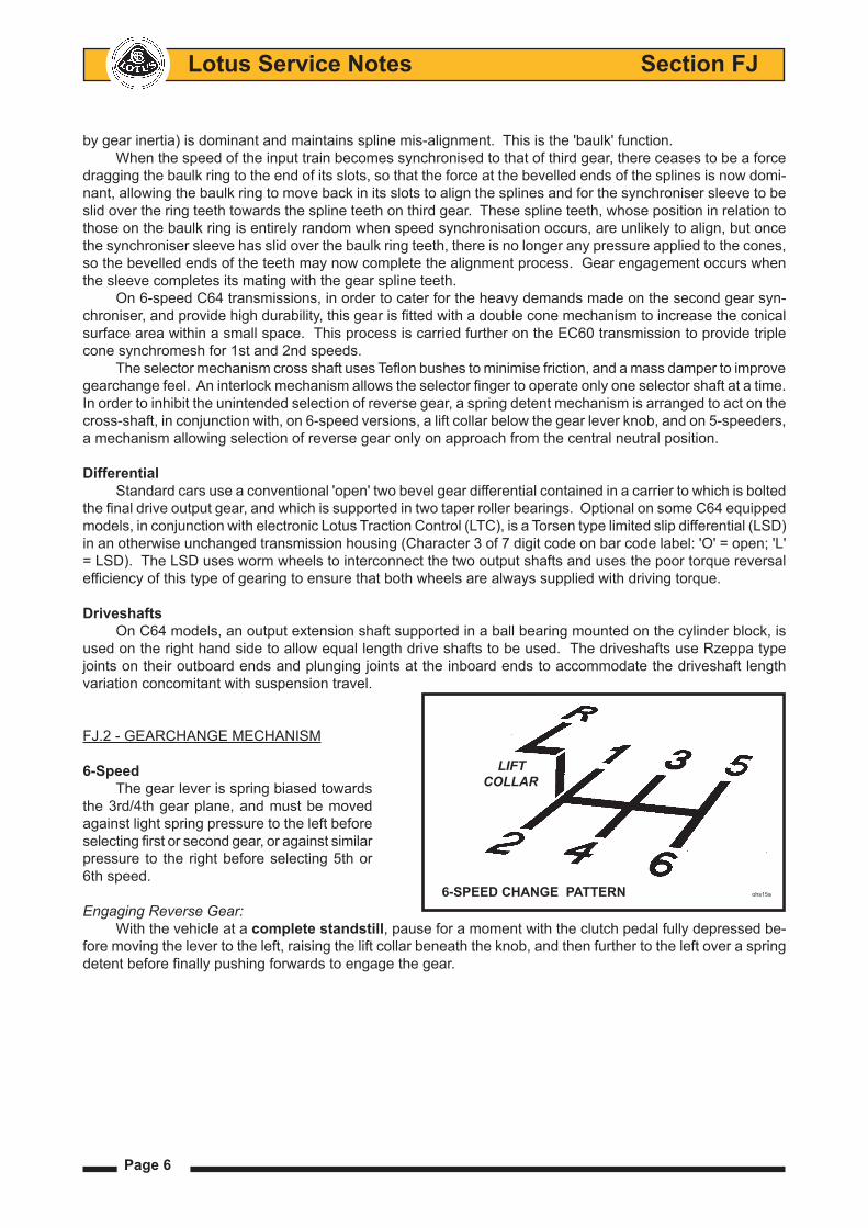
FJ.2 - GEARCHANGE MECHANISM
6-SpeedThe gear lever is spring biased towards
the 3rd/4th gear plane, and must be moved against light spring pressure to the left before selecting first or second gear, or against similar pressure to the right before selecting 5th or 6th speed.
Engaging Reverse Gear:With the vehicle at a complete standstill, pause for a moment with the clutch pedal fully depressed be-
fore moving the lever to the left, raising the lift collar beneath the knob, and then further to the left over a spring detent before finally pushing forwards to engage the gear.
LIFT COLLAR
6-SPEED CHANGE PATTERN ohs15a
Page 7
Lotus Service Notes Section FJ
Crossgate Gearchange Cable Schematic (prior May '07)
Shift
Reverse gate lift collar
Reversegate Crossgate Crossgate cablerelease bellcrank lever cable Shift cable
Gear lever ball pivot Reverse gate Abutment stop arm block f133
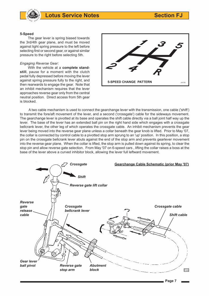
5-SpeedThe gear lever is spring biased towards
the 3rd/4th gear plane, and must be moved against light spring pressure to the left before selecting first or second gear, or against similar pressure to the right before selecting 5th.
Engaging Reverse Gear:
With the vehicle at a complete stand-still, pause for a moment with the clutch pedal fully depressed before moving the lever against spring pressure fully to the right, and then rearwards to engage the gear. Note that an inhibit mechanism requires that the lever approaches reverse gear only from the central neutral position. Direct access from 5th gear is blocked.
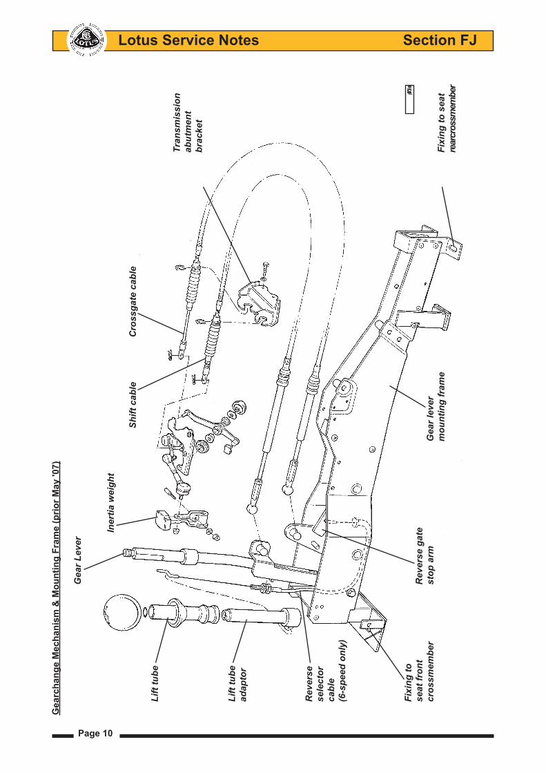
A two cable mechanism is used to connect the gearchange lever with the transmission, one cable ('shift') to transmit the fore/aft movement of the lever, and a second ('crossgate') cable for the sideways movement. The gearchange lever is pivotted at its base and operates the shift cable directly via a ball joint half way up the lever. The base of the lever has an extended ball pin on the right hand side which engages with a crossgate bellcrank lever, the other leg of which operates the crossgate cable. An inhibit mechanism prevents the gear lever being moved into the reverse gear plane unless a collar beneath the gear knob is lifted. Prior to May '07, the collar is connected by control cable to a pivotted stop arm sprung to an 'up' position. In this position, a stop pin on the crossgate bellcrank lever abuts against the end of the stop arm and prevents gearlever movement into the reverse gear plane. When the collar is lifted, the stop arm is pulled down against its spring, to clear the stop pin and allow reverse gate selection. From May '07 on 6-speed cars , lifting the collar raises a boss at the base of the lever above a curved inhibitor block, allowing the lever full leftward movement.
5-SPEED CHANGE PATTERN ohs15b
Lotus Service Notes Section FJ
Page 8
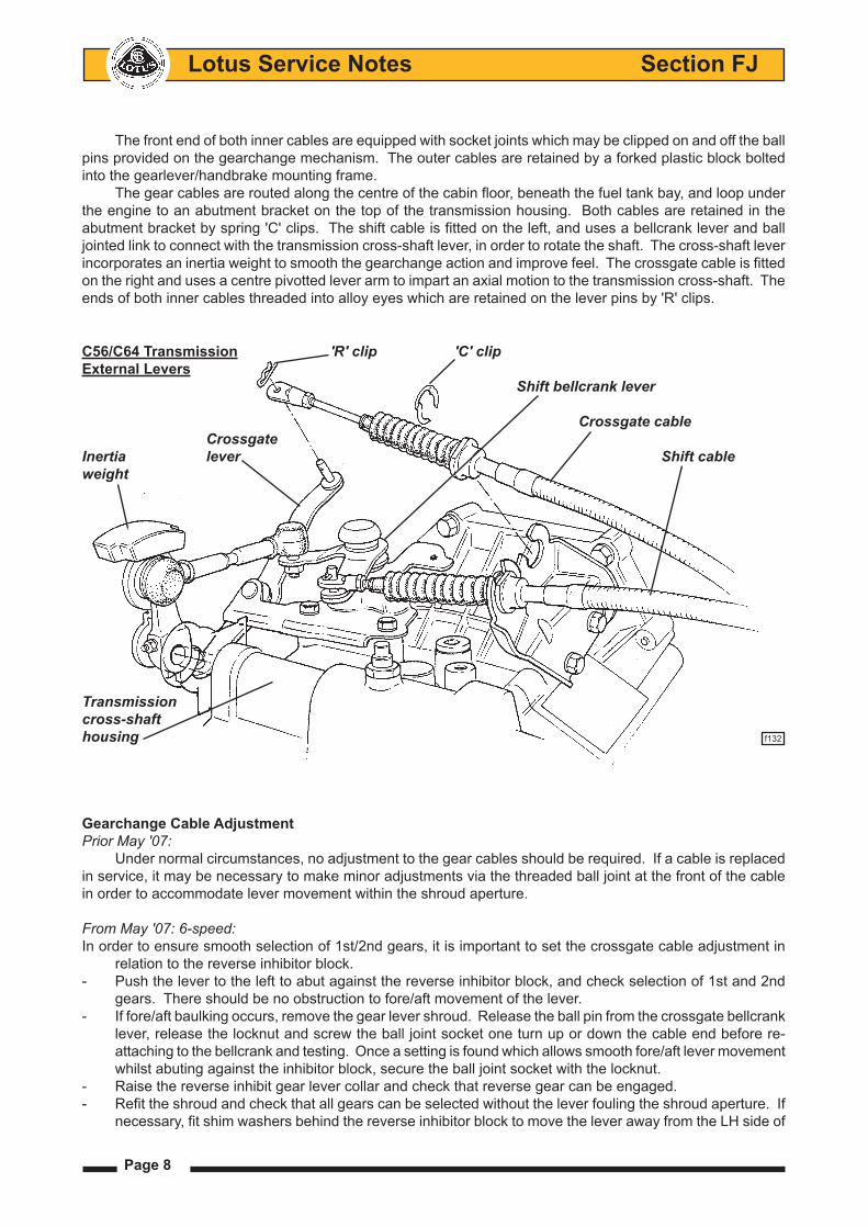
The front end of both inner cables are equipped with socket joints which may be clipped on and off the ball pins provided on the gearchange mechanism. The outer cables are retained by a forked plastic block bolted into the gearlever/handbrake mounting frame.
The gear cables are routed along the centre of the cabin floor, beneath the fuel tank bay, and loop under the engine to an abutment bracket on the top of the transmission housing. Both cables are retained in the abutment bracket by spring 'C' clips. The shift cable is fitted on the left, and uses a bellcrank lever and ball jointed link to connect with the transmission cross-shaft lever, in order to rotate the shaft. The cross-shaft lever incorporates an inertia weight to smooth the gearchange action and improve feel. The crossgate cable is fitted on the right and uses a centre pivotted lever arm to impart an axial motion to the transmission cross-shaft. The ends of both inner cables threaded into alloy eyes which are retained on the lever pins by 'R' clips.
Gearchange Cable AdjustmentPrior May '07:
Under normal circumstances, no adjustment to the gear cables should be required. If a cable is replaced in service, it may be necessary to make minor adjustments via the threaded ball joint at the front of the cable in order to accommodate lever movement within the shroud aperture.
From May '07: 6-speed:In order to ensure smooth selection of 1st/2nd gears, it is important to set the crossgate cable adjustment in
relation to the reverse inhibitor block.- Push the lever to the left to abut against the reverse inhibitor block, and check selection of 1st and 2nd
gears. There should be no obstruction to fore/aft movement of the lever.- If fore/aft baulking occurs, remove the gear lever shroud. Release the ball pin from the crossgate bellcrank
lever, release the locknut and screw the ball joint socket one turn up or down the cable end before re-attaching to the bellcrank and testing. Once a setting is found which allows smooth fore/aft lever movement whilst abuting against the inhibitor block, secure the ball joint socket with the locknut.
- Raise the reverse inhibit gear lever collar and check that reverse gear can be engaged.- Refit the shroud and check that all gears can be selected without the lever fouling the shroud aperture. If
necessary, fit shim washers behind the reverse inhibitor block to move the lever away from the LH side of
C56/C64 Transmission 'R' clip 'C' clipExternal Levers Shift bellcrank lever
Crossgate cable CrossgateInertia lever Shift cableweight
Transmissioncross-shafthousing f132
Page 9
Lotus Service Notes Section FJ
the aperture and re-adjust the crossgate cable as necessary.- If other adjustments have been made, check the alignment of the 3rd/4th lever plane. From the spring
loaded neutral position, it should be possible to smoothly engage 3rd and 4th gears without moving the lever across the gate. If necessary, the ends of the centralising hairpin spring may be reprofiled to reset the neutral plane.
Gearchange Cable ReplacementFor access to the gear cables, the gear lever shroud and parking brake lever trim must be removed: Un-
screw the gear lever knob, remove the single screw each side of the shroud, and withdraw the shroud over the gear and parking brake levers. Remove the engine bay undertray.
At the front end of the cables, unclip the inner cable ball joint sockets from the ball pins on the mechanism levers. Release the outer cable plastic abutment block from the mounting frame. At the rear end of the cables, remove the 'R' clips retaining the inner cable eyes to the levers, and the 'C' clips securing the outer cables to the abutment bracket. Release the 'P' clips and cable ties as necessary to allow the cables to be withdrawn from the car, noting the routing of the cables past the parking brake lever and wiring harness.
Refit in reverse order to removal, paying particular attention to the routing through or alongside the park-ing brake lever mounting frame.
Lotus Service Notes Section FJ
Page 10
Gea
rcha
nge
Mec
hani
sm &
Mou
ntin
g Fr
ame
(prio
r May
'07)
Gea
r Lev
er
Iner
tia w
eigh
t
Shift
cab
le
Cro
ssga
te c
able
Li
ft tu
be
Tr
ansm
issi
on
ab
utm
ent
br
acke
t
Li
ft tu
be
adap
tor
R
ever
se
sele
ctor
cabl
e
(6-s
peed
onl
y)
Fixi
ng to
pl4705mtx
se
at fr
ont
R
ever
se g
ate
cr
ossm
embe
r
st
op a
rm
G
ear l
ever
m
ount
ing
fram
e
Fi
to s
eat
re
ar cr
ossm
embe
r
Page 11
Lotus Service Notes Section FJ
Gearlever Mounting FrameThe gear lever/parking brake lever mounting frame is common to right and left hand drive cars, but is
mounted offset towards the passenger side of the car in order to allow sufficient room for fore/aft adjustment of the driver's seat. The frame is secured to thread inserts in the seat mounting crossmembers by two M8 screws at the rear, which also secure the seat runner/frame, and two M8 screws at the front. All fixings using captive nuts in the seat mounting crossmembers.
Gearlever Replacement (prior May '07)The gear lever alone may be replaced if necessary using the following procedure. Note that fabrication
of the gear lever was changed in February 2005 from using a hexagonal section bar to a thicker round section bar, the better to resist operator abuse. Only the later type will be supplied in service, which if being used to replace the hexagonal type will require fitment of the following parts as a set:
Parts Required Part Number QtyGear Lever - RHD A120F0008S 1Gear Lever - LHD A120F0009S 1Lift Tube, reverse select B120U0017F 1Lift Tube Adaptor B120F6259S 1Spring Clip, lift tube to adaptor B120W6770F 1Knob, gear lever, M10 C120U0012F 1Grub Screw, M5 x 16, gear knob A120W5292F 1Tool, gear lever bush guide A120U0054S 1
Procedure1. Release the grub screw (if applicable) in the front face of the gear lever knob, and unscrew the knob. For
knobs without grub screws, gentle heat may help to soften the thread adhesive. Prise off the spring clip from the top of the lift tube adaptor.
2. Release the two grub screws in the underside of the parking brake lever sleeve and withdraw the sleeve.
3. Remove the two screws securing the front of the gear lever shroud and carefully withdraw the gear/park brake shroud, disconnecting the window switch and hazard lamps switch (if applicable). Take care to prevent scratching the shroud on seat belt fixings or seat runners.
4. Release the reverse selector cable from the gear lever and unhook from the lift tube adaptor. Discard the adaptor.
5. Prise off the gear selector cable socket from the gear lever (use a 10mm spanner).
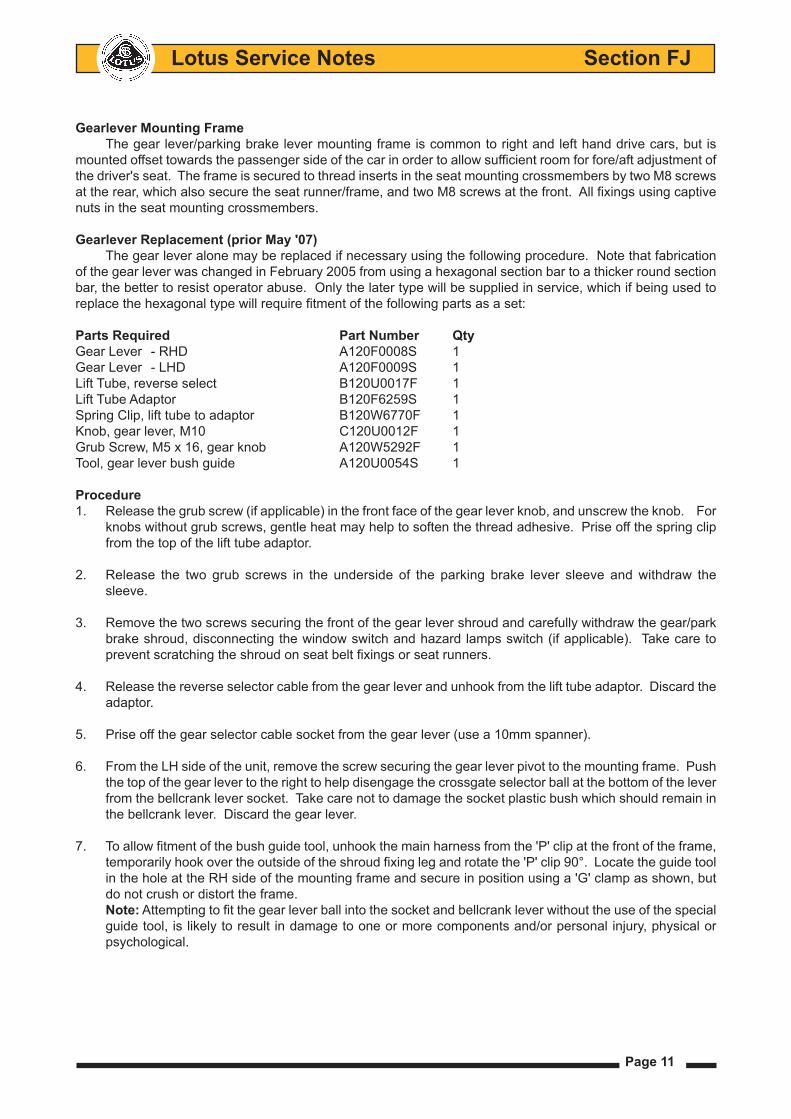
6. From the LH side of the unit, remove the screw securing the gear lever pivot to the mounting frame. Push the top of the gear lever to the right to help disengage the crossgate selector ball at the bottom of the lever from the bellcrank lever socket. Take care not to damage the socket plastic bush which should remain in the bellcrank lever. Discard the gear lever.
7. To allow fitment of the bush guide tool, unhook the main harness from the 'P' clip at the front of the frame, temporarily hook over the outside of the shroud fixing leg and rotate the 'P' clip 90°. Locate the guide tool in the hole at the RH side of the mounting frame and secure in position using a 'G' clamp as shown, but do not crush or distort the frame.
Note: Attempting to fit the gear lever ball into the socket and bellcrank lever without the use of the special guide tool, is likely to result in damage to one or more components and/or personal injury, physical or psychological.
Lotus Service Notes Section FJ
Page 12
Bellcrank lever plastic socket
'G' clamp
Use suitable bolt to push back socket Special tool A120U0054S
(Some components omitted for clarity) f135
8. Push the plastic socket in the bellcrank lever fully into the guide tool to facilitate installation of the gear lever. Apply a dab of mineral oil based lithium grease (e.g. Molykote Longterm W2) to the socket.
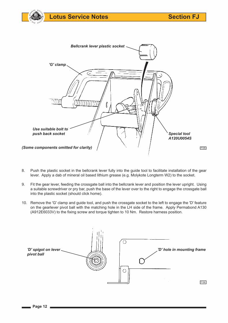
9. Fit the gear lever, feeding the crossgate ball into the bellcrank lever and position the lever upright. Using a suitable screwdriver or pry bar, push the base of the lever over to the right to engage the crossgate ball into the plastic socket (should click home).
10. Remove the 'G' clamp and guide tool, and push the crossgate socket to the left to engage the 'D' feature on the gearlever pivot ball with the matching hole in the LH side of the frame. Apply Permabond A130 (A912E6033V) to the fixing screw and torque tighten to 10 Nm. Restore harness position.
'D' spigot on lever 'D' hole in mounting frame pivot ball
f136
Page 13
Lotus Service Notes Section FJ
11. Fit the new lift tube adaptor onto the gear lever and ensure it is free to slide up and down. Hook in the reverse selector cable and secure to the gear lever abutment. Temporarily fit the new lift tube onto the adaptor and screw on the new gear knob. Adjust the cable to allow correct reverse gear selection and tighten adjuster nuts. Remove gear knob and lift tube. Clip the selector cable onto the gear lever ball.
12. Cut the tie strap securing the old lift tube in the gear lever gaiter and fit the new lift tube using a suitable tie strap. Fit the shroud over the parking brake and gear lever, taking care not to scratch the surface finish, and aligning the flats on the lift tube with those on the lift tube adaptor. Connect the electrical switches as necessary, and retain the shroud with the two screws.
13. Use the new spring clip to secure the lift tube to the adaptor, and fit the new gear knob, tightening the grub screw to orientate the graphic correctly. Fit and secure the parking brake lever sleeve.
14. Check gear selection and reverse inhibit function. Ensure the lift tube returns freely under spring action.
FJ.3 - LUBRICATION
The transmission should be checked for oil leaks, for the correct oil level, and the oil renewed, at intervals specified in the Maintenance Schedule.Transmission oil viscosity;
C64 Gearbox: SAE 75W/90Specification; API GL-4 or GL-5
EC60 Gearbox: SAE 75W/80Specification: API GL-4
Quantity; - 6 speed C64 2.3 litres - 6 speed EC60 2.4 litres - 5 speed C56 1.9 litres
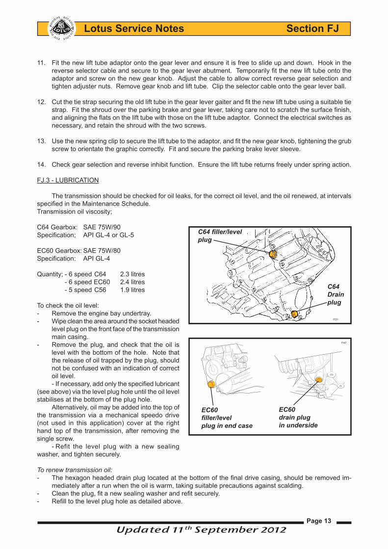
To check the oil level: - Remove the engine bay undertray.- Wipe clean the area around the socket headed
level plug on the front face of the transmission main casing.
- Remove the plug, and check that the oil is level with the bottom of the hole. Note that the release of oil trapped by the plug, should not be confused with an indication of correct oil level.- If necessary, add only the specified lubricant
(see above) via the level plug hole until the oil level stabilises at the bottom of the plug hole.
Alternatively, oil may be added into the top of the transmission via a mechanical speedo drive (not used in this application) cover at the right hand top of the transmission, after removing the single screw.
- Refit the level plug with a new sealing washer, and tighten securely.
To renew transmission oil:- The hexagon headed drain plug located at the bottom of the final drive casing, should be removed im-
mediately after a run when the oil is warm, taking suitable precautions against scalding. - Clean the plug, fit a new sealing washer and refit securely.- Refill to the level plug hole as detailed above.
C64filler/level plug
C64 Drain plug
f131
EC60 filler/level plug in end case
f147
EC60 drain plug in underside
Updated 11th September 2012
Lotus Service Notes Section FJ
Page 14
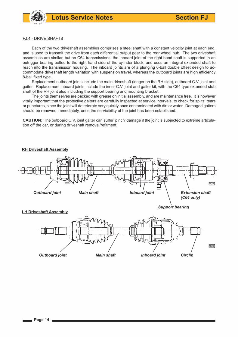
FJ.4 - DRIVE SHAFTS
Each of the two driveshaft assemblies comprises a steel shaft with a constant velocity joint at each end, and is used to transmit the drive from each differential output gear to the rear wheel hub. The two driveshaft assemblies are similar, but on C64 transmissions, the inboard joint of the right hand shaft is supported in an outrigger bearing bolted to the right hand side of the cylinder block, and uses an integral extended shaft to reach into the transmission housing. The inboard joints are of a plunging 6-ball double offset design to ac-commodate driveshaft length variation with suspension travel, whereas the outboard joints are high efficiency 8-ball fixed type.
Replacement outboard joints include the main driveshaft (longer on the RH side), outboard C.V. joint and gaiter. Replacement inboard joints include the inner C.V. joint and gaiter kit, with the C64 type extended stub shaft of the RH joint also including the support bearing and mounting bracket.
The joints themselves are packed with grease on initial assembly, and are maintenance free. It is however vitally important that the protective gaiters are carefully inspected at service intervals, to check for splits, tears or punctures, since the joint will deteriorate very quickly once contaminated with dirt or water. Damaged gaiters should be renewed immediately, once the servicibility of the joint has been established.
CAUTION: The outboard C.V. joint gaiter can suffer 'pinch' damage if the joint is subjected to extreme articula-tion off the car, or during driveshaft removal/refitment.
RH Driveshaft Assembly
f128
Outboard joint Main shaft Inboard joint Extension shaft (C64 only)
Support bearingLH Driveshaft Assembly
f129
Outboard joint Main shaft Inboard joint Circlip
Page 15
Lotus Service Notes Section FJ
Clicking noises, torque reversal 'clonks', or shudder and vibration when accelerating are all possible symp-toms of worn C.V. joints. It should not be possible to discern any free play in a joint, but care must be taken not to confuse this with transmission backlash, which will certainly be evident. Any symptoms that could be due to worn driveshaft joint assemblies, should be investigated and rectified without delay, since a broken driveshaft can cause considerable damage. Safety considerations should always be accorded the highest priority.
The inboard C.V. joint is equipped with a male splined spigot shaft which engages with the female splines of the differential output sun gear, with the LH shaft retained by a round section spring circlip on its end, and the RH shaft retained by the extension shaft support bearing. Each of the two transmission output oil seals runs on a stepped shoulder on the C.V. joint spigot shaft. The stub shaft of each outboard joint is splined into the wheel hub, and retained by a nut on the threaded end of the shaft.
Driveshaft Assembly ReplacementRemoving a driveshaft assembly from the transmission will result in some loss of transmission lubricant.
It may be preferred to drain off some oil via the transmission drain plug beforehand.1. Remove transmission drain plug and drain off approx. 1 litre of oil into a clean container for re-use.
2. Remove the rear road wheel.
3. Remove the split pin from the hub nut and remove the nut and washer (right hand thread on both sides). Before the shaft can be withdrawn from the hub, the top ball joint plinth must be released from the hub carrier (note camber shims fitted), and the toe-link ball joint separated from the carrier. This will allow the hub carrier to be pulled away sufficiently for the driveshaft to be withdrawn, but take care not to strain the brake hose or wheel speed sensor harness.
4. Except C64 RH Driveshaft: The driveshaft inboard joint is retained in the transmission by a round section circlip. The joint may be removed by applying a shock pull to the C.V. joint body using a slide hammer with a forked end.
CAUTION: Do NOT attempt to remove the inboard C.V. joint from the transmission by pulling on the driveshaft. The balls of the inboard joint are restrained for transit purposes only, by a circlip at the end of the ball tracks. Applying an extension force to the joint will damage the balls and require joint replacement. Apply pressure only to the outer body of the joint.
C64 RH Driveshaft: This driveshaft incorporates a bearing for the extension shaft and it is this which retains the shaft in the transmission. Remove the two bolts securing the bearing bracket, and withdraw the complete shaft assembly.
When withdrawing either driveshaft from the transmission, take care not to damage the output oil seal.
6. Before re-fitting a driveshaft, first renew the round section circlip on the end of the inboard joint spigot shaft, and lubricate the circlip with grease. Also, check the condition of the transmission output seal, and renew if necessary. Lubricate the lip of the seal with transmission oil, and grease the corresponding shoulder on the driveshaft (C.V. joint) spigot, to reduce the danger of damaging the seal on assembly.
7. Carefully insert the driveshaft into the transmission, with the two ends of the circlip positioned lowermost, and rotate the shaft if necessary to engage the splines. Press the inboard joint outer until a click indicates the engagement of the retaining circlip, if necessary using a brass drift and hammer. Afterwards, pull on the joint body to check its security. On the C64 right hand shaft, fit the bolts securing the extension shaft bearing to the engine mounted bracket, and torque to 64 Nm.
8. Fit the outer end of the shaft into the hub, and refit the top ball joint plinth to the hub carrier with the cam-ber adjustment shim pack in position. Apply Permabond A130 (A912E7033V) to the threads of the two socket head bolts and torque to 45 Nm.
9. Refit the toe-link into the hub carrier and torque the retaining nut to 55 Nm.
10. Fit the washer and castellated nut to the driveshaft, apply the parking brake and tighten the nut to 220 Nm. Fit a new split pin to lock the nut.
11. With the car on a level surface, top up the transmission oil to the filler/level plug hole.
Lotus Service Notes Section FJ
Page 16
Driveshaft C.V. Joint and/or Gaiter ReplacementThe outboard C.V. joint is supplied complete with main driveshaft to which it is fixed by a spline with a small
helix angle to eliminate any potential backlash. Separation of the shaft from the joint should not be attempted. Note that the RH main shaft is 22mm longer than the LH shaft. Replacement of the outboard joint gaiter entails removal of the complete driveshaft assembly from the car, and removal of the inboard joint from the shaft.1. Remove the driveshaft assembly from the car (see above).
2. Remove the clips securing the inboard joint gaiter without damaging the gaiter if it is to be re-used. Pull the gaiter off the joint outer body, remove the circlip in the end of the joint outer body and match mark the body to the joint inner race before sliding the body off the shaft assembly.
3. Remove the circlip from the end of the shaft and match mark the inboard joint inner race to the shaft before pulling or pressing the race from the shaft. Slide the inboard gaiter off the shaft.
4. Remove the clips securing the outboard gaiter, and slide the gaiter off the shaft.
5. Inspection & Cleaning: Complete disassembly of either joint is NOT recommended. The separate com-ponents are a precision fit and develop their own individual wear patterns, such that any interchanging or re-orientation of parts is likely to result in premature failure.
If the grease in the joint is contaminated with dirt or water, it is likely that the joint is damaged, and should be replaced. If the grease is not contaminated, the joint should be degreased by soaking in a suitable solvent (NOT petrol), and then carefully inspected. Tilt the inner race to one side to expose each ball. Severe pitting, galling, play between ball and its cage window, any cracking or damage to the cage, or pitting, galling or chips in raceways, call for joint replacement.
If the joint is found to be serviceable, it must be repacked with the special grease provided. Pack the grease into the joint itself and also into the inside of the new gaiter.
NOTE: The grease provided in the kits is specially formulated for wear resistance and durability. DO NOT use substitutes or mix with other lubricants. The grease specification and quantity also differs for inboard and outboard joints:
Inboard: 140g NKG 205 99-1089#BJ95 Outboard: 130g NTG 2218M 99-729#BJ100 (inboard grease is also supplied as the inboard joint must
be removed before fitting outboard gaiter)
6. Slide the new outboard gaiter and smaller retaining clip onto the shaft. Fit the gaiter into the grooves on the outboard joint body and the driveshaft, and secure with the clips provided.
7. Slide the new outboard gaiter and retaining clip onto the driveshaft and press the joint inner race onto the driveshaft splines with the match marks aligned (if re-using joint). Retain with a new circlip.
8. Fit the inboard joint body to the shaft assembly with the match marks aligned (if re-using joint), and fit a new circlip into the end of the housing to retain the joint.
9. Fit gaiter into the grooves on the joint outer body and driveshaft and secure with new gaiter clips.
10. Refit the driveshaft to the car (see above).
Extension Shaft Support Bearing - C64The ball bearing supporting the RH driveshaft extension shaft to the engine block is mounted in a housing
which is bolted to a bracket on the engine block. The bearing is sealed and maintenance free, and is included as part of the inboard C.V. joint assembly, but may if necessary be renewed by the following procedure:
1. Remove the RH driveshaft assembly (see above).
2. Using a press, remove the dust shield from the inboard end of the shaft.
3. Remove the circlip from the outboard face of the bearing housing, and press or pull the housing from the bearing.
Page 17
Lotus Service Notes Section FJ
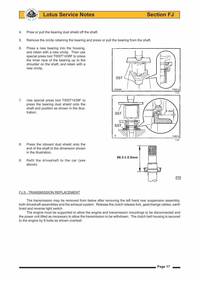
4. Prise or pull the bearing dust shield off the shaft.
5. Remove the circlip retaining the bearing and press or pull the bearing from the shaft.
6. Press a new bearing into the housing, and retain with a new circlip. Then use special press tool T000T1438F to press the inner race of the bearing up to the shoulder on the shaft, and retain with a new circlip.
7. Use special press tool T000T1439F to press the bearing dust shield onto the shaft and position as shown in the illus-tration.
8. Press the inboard dust shield onto the end of the shaft to the dimension shown in the illustration.
9. Refit the driveshaft to the car (see above).
FJ.5 - TRANSMISSION REPLACEMENT
The transmission may be removed from below after removing the left hand rear suspension assembly, both driveshaft assemblies and the exhaust system. Release the clutch release fork, gearchange cables, earth braid and reverse light switch.
The engine must be supported to allow the engine and transmission mountings to be disconnected and the power unit tilted as necessary to allow the transmission to be withdrawn. The clutch bell housing is secured to the engine by 8 bolts as shown overleaf.
86.5 ± 0.5mm
f127
f125
f126
Lotus Service Notes Section FJ
Page 18
FJ.6 - TRANSMISSION OVERHAUL
The overhauling of the Toyota supplied type C64/C56 transmission, is detailed in separate publication E120T0327J.
For the EC60 transmission, a CD under part number T000T1523F is available; choose:- Repair Manual- Transmission- scroll down to find EC60 MANUAL TRANSAXLE in left hand column.
When applicable, select '2010/01 -'
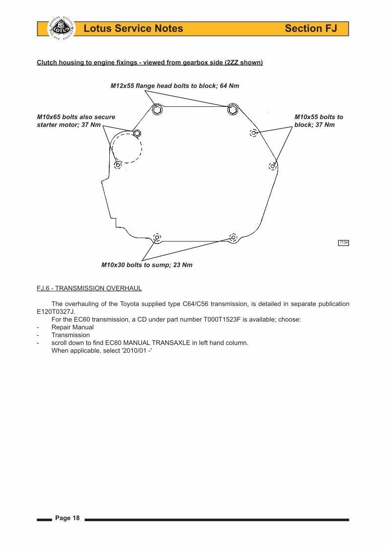
Clutch housing to engine fixings - viewed from gearbox side (2ZZ shown)
M12x55flangeheadboltstoblock;64Nm
M10x65 bolts also secure M10x55 bolts tostartermotor;37Nm block;37Nm
f134
M10x30boltstosump;23Nm
Page 19
Lotus Service Notes Section FJ
Transmission Special ToolsDescription LotusPartNo. Press Dolly, driveshaft bearing T000T11438F Press Dolly, driveshaft bearing shield T000T1439F Oil Seal Puller T000T1445SDifferential Preload Adaptor T000T1446S5th/6th Gear Puller Kit T000T1447comprises: Upper Plate T000T1447/1 Centre Bolt T000T1447/2 Arm (x3) T000T1447/3 Adaptor T000T1447/45th/6th Synchro Hub Puller Kit T000T1448comprises Hanger T000T1448/1 Slide Arm (x2) T000T1448/2 Centre Bolt T000T1448/3 Claw no.2 (x2) T000T1448/4 Holder T000T1448/5Output Shaft Seal Replacer Dolly, LH T000T1459FOutput Shaft Seal Replacer Dolly, RH T000T Output Shaft Seal Replacer Handle T000T1460F
Transmission Overhaul Notes1. Removing and installing 5th and 6th driven gears from the end of the ouput shaft requires considerable
force. The specified puller tools should be used, but when pulling 5th speed driven gear, the claws of the tool may require some grinding to allow complete and proper fitment, and an anti-spreading device is rec-ommended to be fitted around the three claws. Striking the puller bolt with a hammer in between tightening steps will help shock the gear from its interference fit, and engaging two gears to lock the transmission will also aid the process.
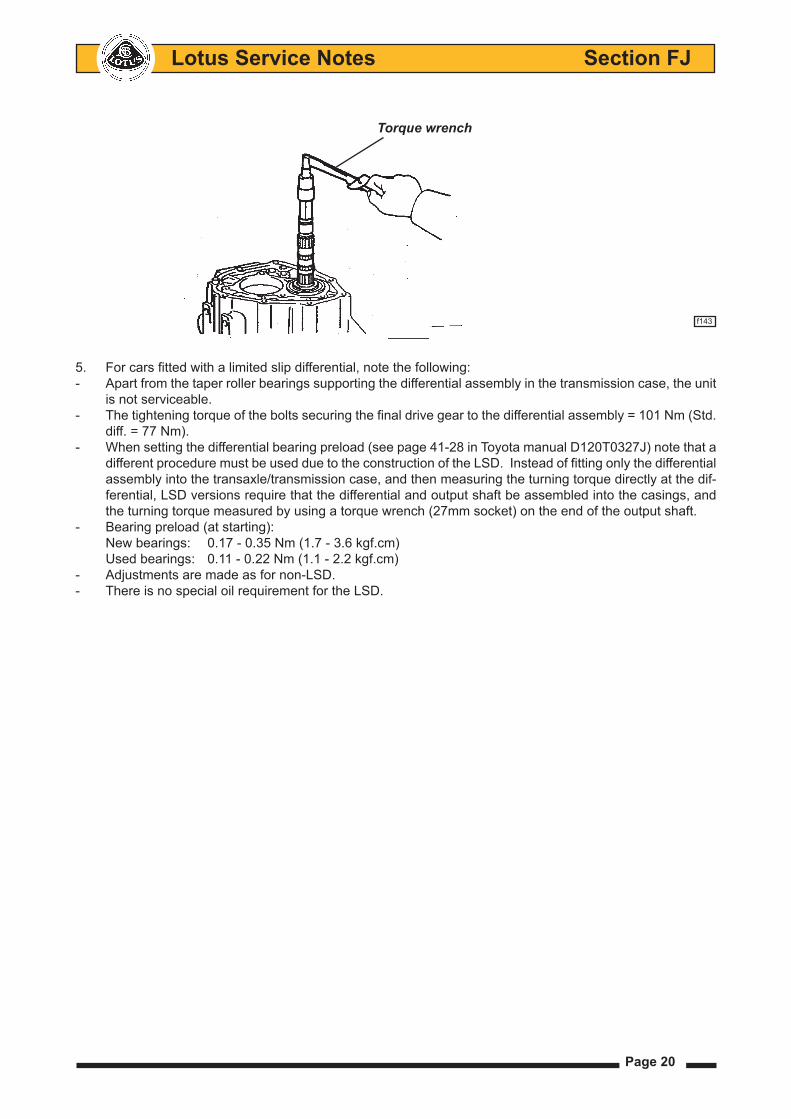
2. The preload on the differential carrier taper roller bearings is controlled by shims between the bearing outer race and the clutch housing, and is determined by installing the final drive assembly in an otherwise empty casing, and measuring the steady rotation torque.
3. If the input shaft oil seal is to be replaced, the bearing should also be renewed since this is likely to be damaged during oil seal removal.
4. The transmission cross-shaft reverse select compression spring shown in the Toyota Repair Manual is removed for the Lotus application. When fitting a replacement transmission, compare the cross shaft spring loading of the old and new units to determine whether this modification has been carried out.
Page 20
Lotus Service Notes Section FJ
5. For cars fitted with a limited slip differential, note the following:- Apart from the taper roller bearings supporting the differential assembly in the transmission case, the unit
is not serviceable.- The tightening torque of the bolts securing the final drive gear to the differential assembly = 101 Nm (Std.
diff. = 77 Nm).- When setting the differential bearing preload (see page 41-28 in Toyota manual D120T0327J) note that a
different procedure must be used due to the construction of the LSD. Instead of fitting only the differential assembly into the transaxle/transmission case, and then measuring the turning torque directly at the dif-ferential, LSD versions require that the differential and output shaft be assembled into the casings, and the turning torque measured by using a torque wrench (27mm socket) on the end of the output shaft.
- Bearing preload (at starting):New bearings: 0.17 - 0.35 Nm (1.7 - 3.6 kgf.cm)Used bearings: 0.11 - 0.22 Nm (1.1 - 2.2 kgf.cm)
- Adjustments are made as for non-LSD.- There is no special oil requirement for the LSD.
Torque wrench
f143