Embed Size (px)
Citation preview
Low Impedance Cable
FieldInstallation, Manual
TOTAL PROTECTION SOLUTIONS® LOW IMPEDANCE AWG 10 INSTALLATION MANUAL PN 750-0092-008 A01
#10 AWG Low Impedance Cable
®
®
TEL: 800-853-8265 www.InnosysPower.com
TOTAL PROTECTION SOLUTIONS® LOW IMPEDANCE AWG 10 INSTALLATION MANUAL2
Before Installation
Cable Routing
WYE Configurations
Termination Instructions
Delta Configuration
Terminal Instructions
3
3
4-7
8-12
TABLE OF CONTENTS
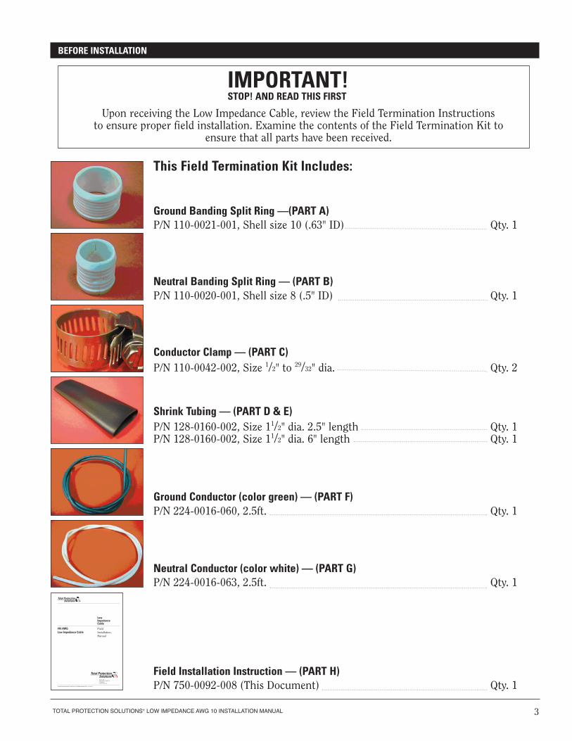
This Field Termination Kit Includes:
Ground Banding Split Ring —(PART A)P/N 110-0021-001, Shell size 10 (.63" ID) Qty. 1
Neutral Banding Split Ring — (PART B)P/N 110-0020-001, Shell size 8 (.5" ID) Qty. 1
Conductor Clamp — (PART C)P/N 110-0042-002, Size 1/2" to 29/32" dia. Qty. 2
Shrink Tubing — (PART D & E)P/N 128-0160-002, Size 11/2" dia. 2.5" length Qty. 1P/N 128-0160-002, Size 11/2" dia. 6" length Qty. 1
Ground Conductor (color green) — (PART F)P/N 224-0016-060, 2.5ft. Qty. 1
Neutral Conductor (color white) — (PART G)P/N 224-0016-063, 2.5ft. Qty. 1
Field Installation Instruction — (PART H)P/N 750-0092-008 (This Document) Qty. 1
TOTAL PROTECTION SOLUTIONS® LOW IMPEDANCE AWG 10 INSTALLATION MANUAL 3
IMPORTANT!STOP! AND READ THIS FIRST
BEFORE INSTALLATION
Low Impedance Cable
FieldInstallation, Manual
�� �� ��� � � �� � ��� � �� � �� ��� � � � �� � ��� � � � � � � � �� � ������ � �� ������ � �� � � � � � PN 750-0095-001
Total ProtectionSolutions
#10 AWG Low Impedance Cable
®
P.O. Box 3760 Winter Park, FL 32790 USA 1.800.647.1911 www.TPSsurge.com
Upon receiving the Low Impedance Cable, review the Field Termination Instructions to ensure proper field installation. Examine the contents of the Field Termination Kit to
ensure that all parts have been received.
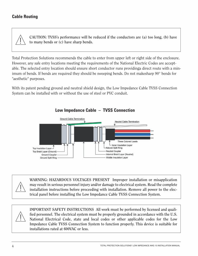
Total Protection Solutions recommends the cable to enter from upper left or right side of the enclosure.However, any safe entry locations meeting the requirements of the National Electric Codes are accept-able. The selected entry location should ensure short conductor runs providinga direct route with a min-imum of bends. If bends are required they should be sweeping bends. Do not makesharp 90° bends for"aesthetic" purposes.
With its patent pending ground and neutral shield design, the Low Impedance Cable TVSS ConnectionSystem can be installed with or without the use of steel or PVC conduit.
TOTAL PROTECTION SOLUTIONS® LOW IMPEDANCE AWG 10 INSTALLATION MANUAL4
CAUTION: TVSS’s performance will be reduced if the conductors are (a) too long, (b) haveto many bends or (c) have sharp bends.!
Low Impedance Cable – TVSS Connection
WARNING: HAZARDOUS VOLTAGES PRESENT Improper installation or misapplicationmay result in serious personnel injury and/or damage to electrical system. Read the completeinstallation instructions before proceeding with installation. Remove all power to the elec-trical panel before installing the Low Impedance Cable TVSS Connection System.
!
IMPORTANT SAFETY INSTRUCTIONS All work must be performed by licensed and quali-fied personnel. The electrical system must be properly grounded in accordance with the U.S.National Electrical Code, state and local codes or other applicable codes for the LowImpedance Cable TVSS Connection System to function properly. This device is suitable forinstallations rated at 600VAC or less.
!
Cable Routing
TOTAL PROTECTION SOLUTIONS® LOW IMPEDANCE AWG 10 INSTALLATION MANUAL 5
WYE Configuration Termination instructions
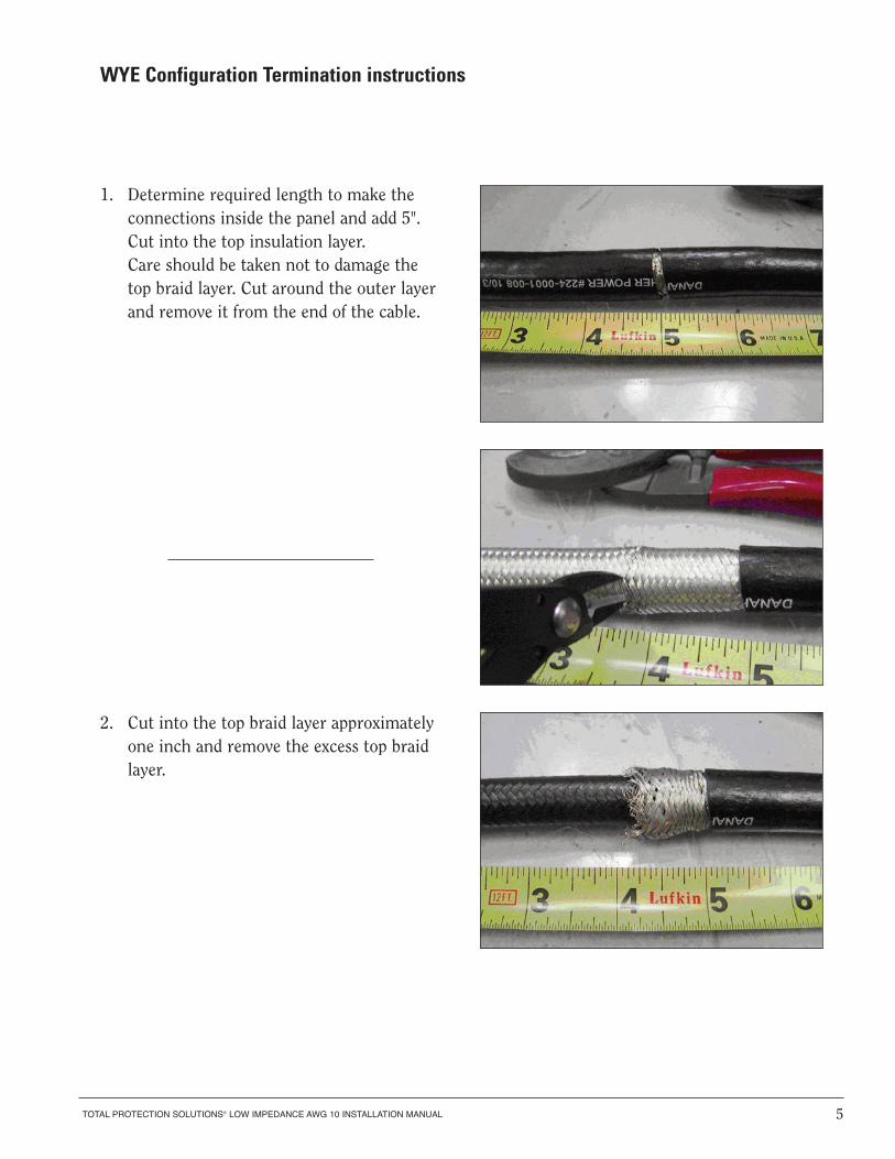
1. Determine required length to make the connections inside the panel and add 5". Cut into the top insulation layer. Care should be taken not to damage the top braid layer. Cut around the outer layer and remove it from the end of the cable.
2. Cut into the top braid layer approximately one inch and remove the excess top braid layer.
TOTAL PROTECTION SOLUTIONS® LOW IMPEDANCE AWG 10 INSTALLATION MANUAL6
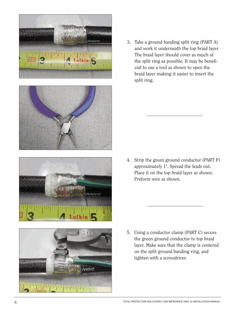
3. Take a ground banding split ring (PART A) and work it underneath the top braid layer. The braid layer should cover as much of the split ring as possible. It may be benefi-cial to use a tool as shown to open the braid layer making it easier to insert the split ring.
4. Strip the green ground conductor (PART F)approximately 1". Spread the leads out. Place it on the top braid layer as shown. Preform wire as shown.
5. Using a conductor clamp (PART C) secure the green ground conductor to top braid layer. Make sure that the clamp is centered on the split ground banding ring, and tighten with a screwdriver.
TOTAL PROTECTION SOLUTIONS® LOW IMPEDANCE AWG 10 INSTALLATION MANUAL 7
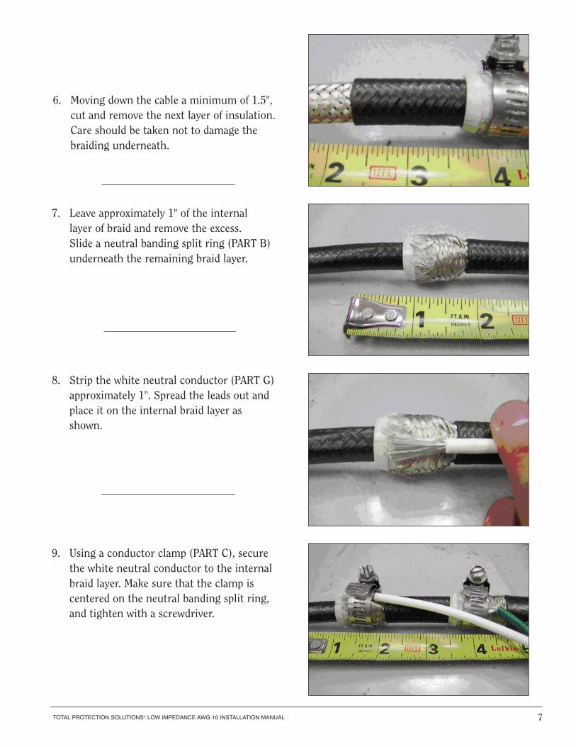
6. Moving down the cable a minimum of 1.5", cut and remove the next layer of insulation.Care should be taken not to damage the braiding underneath.
8. Strip the white neutral conductor (PART G)approximately 1". Spread the leads out and place it on the internal braid layer as shown.
7. Leave approximately 1" of the internal layer of braid and remove the excess. Slide a neutral banding split ring (PART B) underneath the remaining braid layer.
9. Using a conductor clamp (PART C), secure the white neutral conductor to the internalbraid layer. Make sure that the clamp is centered on the neutral banding split ring, and tighten with a screwdriver.
8
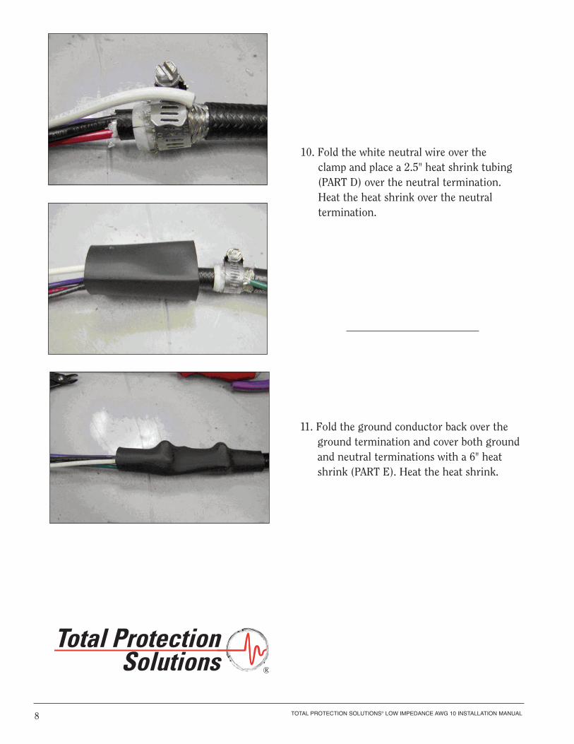
10. Fold the white neutral wire over the clamp and place a 2.5" heat shrink tubing (PART D) over the neutral termination. Heat the heat shrink over the neutral termination.
11. Fold the ground conductor back over the ground termination and cover both ground and neutral terminations with a 6" heat shrink (PART E). Heat the heat shrink.
®
TOTAL PROTECTION SOLUTIONS® LOW IMPEDANCE AWG 10 INSTALLATION MANUAL
TOTAL PROTECTION SOLUTIONS® LOW IMPEDANCE AWG 10 INSTALLATION MANUAL 9
Delta Configuration Terminal Instructions
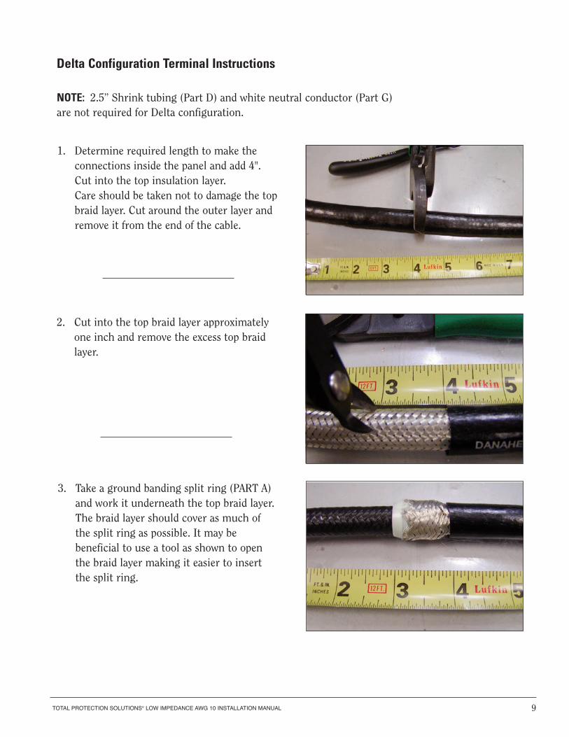
1. Determine required length to make the connections inside the panel and add 4". Cut into the top insulation layer. Care should be taken not to damage the topbraid layer. Cut around the outer layer and remove it from the end of the cable.
2. Cut into the top braid layer approximately one inch and remove the excess top braid layer.
3. Take a ground banding split ring (PART A) and work it underneath the top braid layer. The braid layer should cover as much of the split ring as possible. It may be beneficial to use a tool as shown to open the braid layer making it easier to insert the split ring.
NOTE: 2.5” Shrink tubing (Part D) and white neutral conductor (Part G)are not required for Delta configuration.
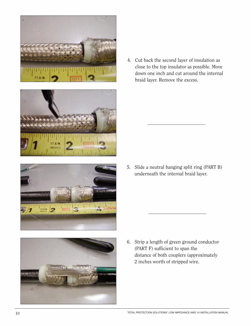
4. Cut back the second layer of insulation as close to the top insulator as possible. Move down one inch and cut around the internal braid layer. Remove the excess.
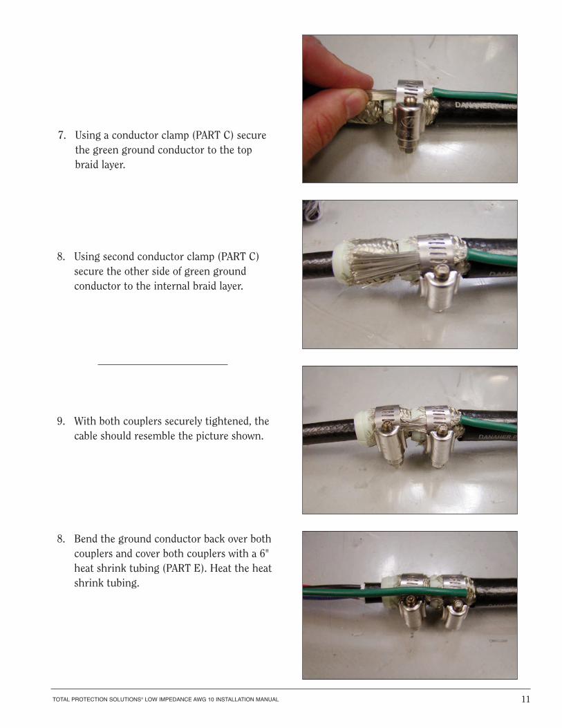
5. Slide a neutral banging split ring (PART B) underneath the internal braid layer.
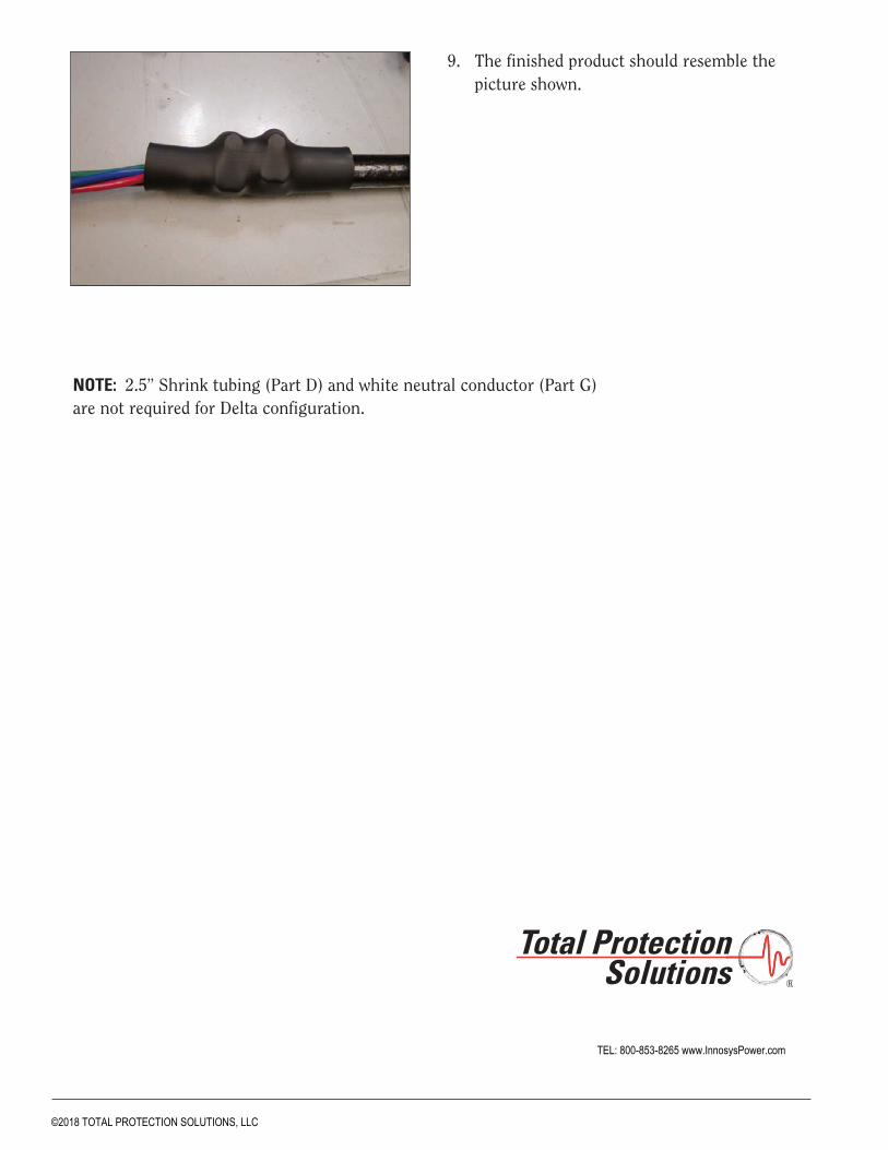
6. Strip a length of green ground conductor (PART F) sufficient to span thedistance of both couplers (approximately 2 inches worth of stripped wire.
TOTAL PROTECTION SOLUTIONS® LOW IMPEDANCE AWG 10 INSTALLATION MANUAL10
TOTAL PROTECTION SOLUTIONS® LOW IMPEDANCE AWG 10 INSTALLATION MANUAL 11
7. Using a conductor clamp (PART C) secure the green ground conductor to the topbraid layer.
8. Using second conductor clamp (PART C) secure the other side of green ground conductor to the internal braid layer.
9. With both couplers securely tightened, the cable should resemble the picture shown.
8. Bend the ground conductor back over both couplers and cover both couplers with a 6" heat shrink tubing (PART E). Heat the heatshrink tubing.
®
9. The finished product should resemble the picture shown.
NOTE: 2.5” Shrink tubing (Part D) and white neutral conductor (Part G)are not required for Delta configuration.
TEL: 800-853-8265 www.InnosysPower.com
©2018 TOTAL PROTECTION SOLUTIONS, LLC


![ALUMINUM ELECTROLYTIC CAPACITORS · 2010-01-13 · 59 SX [ For Low Impedance & Low E.S.R ]2,000~5,000hrs. at 105°C 63 SY [ For Low Impedance and Low E.S.R Suitable for Output of](https://img.pdfslide.net/doc/110x75/5e73a82112217f1b2823b4e2/aluminum-electrolytic-capacitors-2010-01-13-59-sx-for-low-impedance-low.jpg)