Embed Size (px)
Citation preview
LR 8882 H323VIDEOPHONE
USER'S MANUAL
LR 8882 H323 User's ManualVersion AJuly 2005 P/N: W0501005
International Headquarters
18th Fl., 166, Chien-Yi Rd., Chung Ho, Taipei Hsien, Taiwan (235) Phone: +886 (0)2 8226 5800 Fax: +886 (0)2 8226 5801http://www.leadtek.com.tw E-Mail: [email protected]
United States Headquarters
46732 Lakeview Blvd., Fremont, CA 94538, U.S.A.Phone: +1 510 490 8076 Fax: +1 510 490 7759http://www.leadtek.com
Europe Headquarters
Phone: + Fax: +http://www.leadtek.nl
Antennestraat 16 1322 AB, Almere, The Netherlands31 (0)36 536 5578 31 (0)36 536 2215
Copyright 2005 Leadtek Research Inc. All rights reserved.
No part of this document may be copied or reproduced in any form or by any means without the prior written consent of Leadtek Research Inc.
Leadtek makes no warranties with respect to this documentation and disclaims any implied warranties of merchantability, quality, or fitness for any particular purpose. The information in this document is subject to change without notice. Leatek reserves the right to make revisions to this publication without obligation to notify any person or entity of any such changes.
Trademarks or brand names mentioned herein are trademarks or registered trademarks of their respective owners.
Table of Contents
1 Getting Started ............................................................. 1Overview ........................................................................ 1
Feature highlights ........................................................... 1
Hardware specifications ................................................. 2LED status ........................................................................ 2
Network connection(modem)............................................ 3
Video input........................................................................ 3
Video output...................................................................... 3
Audio input ...................................................................... 3
Audio output..................................................................... 3
VideoPhone LR 8882 H323 packaging description ....... 4
2 What's In The Package ............................................... 5
3 Getting to Know Your LR 8882 H323 ....................... 6Front view ...................................................................... 6
LEDs................................................................................ 9
Rear view ..................................................................... 11
Side view ...................................................................... 11
4 Installation ................................................................. 12
Installing the unit .......................................................... 12
Using external devices (Optional) ................................ 14
Table of Contents
5 System Setup ................................................................ 15
ADSL/Constant ADSL/Single, Public, & Fixed IP ...... 16When the IP is used exclusively by LR 8882 H323 ................... 16
ADSL/Constant ADSL/Multiple, Public, & Fixed IP ... 17When LR 8882 H323 uses one of the IPs
(without a DHCP server connected) ........................................ 17
ADSL/Timing ADSL/Single, Public, & Dynamic IP.... 18 When the ADSL is used exclusively by LR 8882 H323 ........... 18
Cable/Single, Public, & Dynamic IP............................. 19 When the IP is used exclusively by LR 8882 H323 .................. 19
LAN/No Firewall or NAT ............................................ 20With a DHCP server connected ............................................... 20
Without a DHCP server connected .......................................... 21
LAN/Firewall with Packet Filter .................................. 22With a DHCP server connected ................................................ 22
Without a DHCP server connected ........................................... 23
LAN/Firewall with NAT & Packet Filter ...................... 24With a DHCP server connected ................................................ 24
Without a DHCP server connected ........................................... 25
6 Making a Call ............................................................. 26
Before making a video call ........................................... 26
Making a video call ...................................................... 27
7 Using OSD Menus ...................................................... 28Outbox ......................................................................... 28
Network Setup ............................................................. 29Bandwidth ..................................................................... 29
IP Setup ........................................................................... 30
NAT Setup ....................................................................... 31
GK Setup ......................................................................... 32
Missed Calls ................................................................. 33
Table of Contents
Phonebook .................................................................... 34
Add ................................................................................. 34
List ................................................................................. 35
Edit contact .......................................................................... 35
Delete contact ...................................................................... 36
Make call ............................................................................ 36
InBox ............................................................................ 37
Phone Setup .................................................................. 38
Time Setup ...................................................................... 38
Language Setup ............................................................... 39
Software update .............................................................. 40
Return default ................................................................ 41
Calls Setup .................................................................... 42
Communication mode ..................................................... 42
Caller ID ......................................................................... 43
T.140 .............................................................................. 44
Auto answer .................................................................... 45
Auto answer rings ........................................................... 46
Information .................................................................. 47
8 OSD Menu Tree ........................................................... 48
9 Trouble Shooting ......................................................... 49
10 Tech Support ............................................................... 50
11 Limited Warranty ....................................................... 51
12 FCC Statement ............................................................ 52
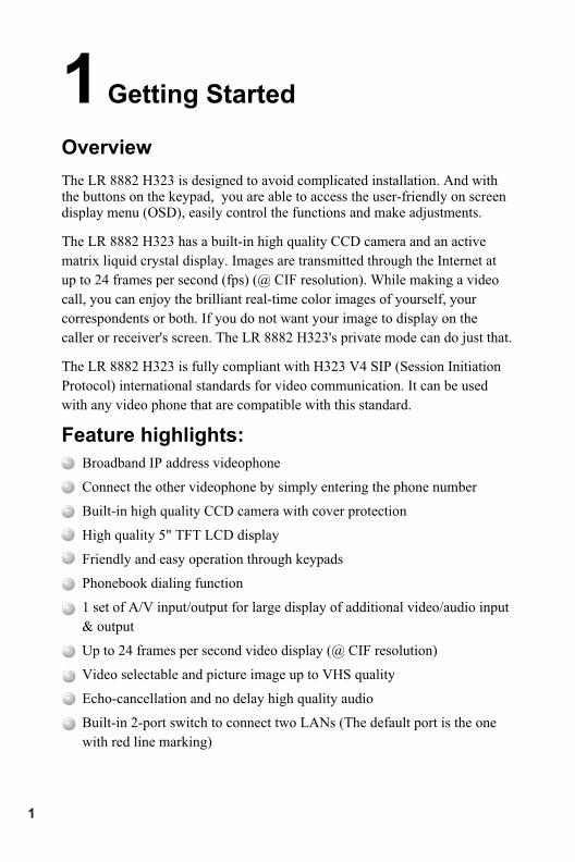
Overview
The LR 8882 H323 is designed to avoid complicated installation. And with the buttons on the keypad, you are able to access the user-friendly on screen display menu (OSD), easily control the functions and make adjustments.
The LR 8882 H323 has a built-in high quality CCD camera and an active
matrix liquid crystal display. Images are transmitted through the Internet at
up to 24 frames per second (fps) (@ CIF resolution). While making a video
call, you can enjoy the brilliant real-time color images of yourself, your
correspondents or both. If you do not want your image to display on the
caller or receiver's screen. The LR 8882 H323's private mode can do just that.
The LR 8882 H323 is fully compliant with H323 V4 SIP (Session Initiation
Protocol) international standards for video communication. It can be used
with any video phone that are compatible with this standard.
Feature highlights:
Broadband IP address videophone
Connect the other videophone by simply entering the phone number
Built-in high quality CCD camera with cover protection
High quality 5" TFT LCD display
Friendly and easy operation through keypads
Phonebook dialing function
1 set of A/V input/output for large display of additional video/audio input
& output
Up to 24 frames per second video display (@ CIF resolution)
Video selectable and picture image up to VHS quality
Echo-cancellation and no delay high quality audio
Built-in 2-port switch to connect two LANs (The default port is the one
with red line marking)
1 Getting Started
1
LED Status
VideoPhone LR 8882 H323 is ON and in standby mode
The " " LED is on permanently.
Video connection indication
If the video connection is establish, the Video LED turns on.
When the video connection terminates, this Video LED turns off.
En Service
Hardware Specifications
LR 8882 H323 User's Manual 2
Network connections(modem) The system is connected to an external ADSL modem. The characteristics
are:
·
Video Input
The video input features are:
· Internal CCD camera
· Focal length is adjustable to cover 2.5 meters wide at a distance of 3
meters
· Focus(rotation of lens) is manually controlled by the end user
· Capability to adjust brightness and contrast. These parameters
are controlled via the roller
· Support for 1 Audio/Video input
Video Output
· Support for 1 Audio/Video
Audio Input
·
·
Audio Output
IP: 2 Ethernet ports (RJ-45) of 10/100 Mb/s, one of them with the red
line marking indicates that the Ethernet cable connector (in red color)
should be plugged into it.
output
The audio input features are:
The handset microphone
The built-in hands-free internal microphone
The user can adjust the sound volume with " " and " " keys on his
VideoPhone LR 8882 H323.
The audio is output to the VideoPhone LR 8882 H323 speaker (or handset
depends if the user is using the hands-free function).
3
VideoPhone LR 8882 H323 packaging description
The VideoPhone LR 8882 H323 package includes:
! LR 8882 H323 Videophone.
! VideoPhone LR 8882 H323 user manual.
!
!
!
!
A wired handset & cable.
Each set of power cord / power adaptor comes with a secure lock
mechanical design that is capable of connecting VideoPhone LR
8882 H323 tightly.
An ethernet cable is used to connect VideoPhone LR 8882 H323 to
an ADSL modem either directly or through a PLT (optional).
An A/V Convertible Cable which provides one pair of Audio/Video
input (with green ring near the connector) of RCA female
connectors and one pair of Audio/Video output (with red ring near
the connector) of RCA female connectors.
LR 8882 H323 User's Manual 4
2 What's In The Package
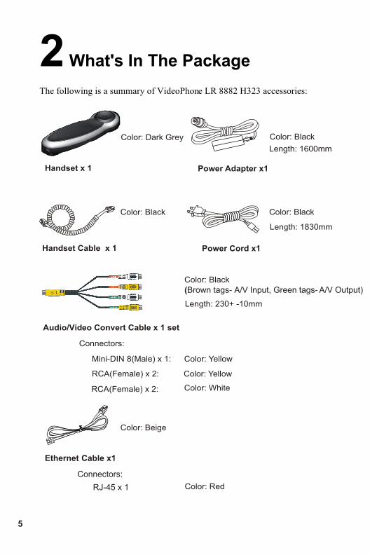
The following is a summary of VideoPhone LR 8882 H323 accessories:
Handset x 1
Color: Dark Grey
Handset Cable x 1
Color: Black
Power Cord x1
Power Adapter x1
Color: Black
Length: 1600mm
Color: Black
Length: 1830mm
Audio/Video Convert Cable x 1 set
Color: Black
Length: 230+ -10mm
Connectors:
Mini-DIN 8(Male) x 1: Color: Yellow
RCA(Female) x 2: Color: Yellow
RCA(Female) x 2: Color: White
Ethernet Cable x1
Connectors:
Color: Beige
Color: Red RJ-45 x 1
5
(Brown tags- A/V Input, Green tags- A/V Output)
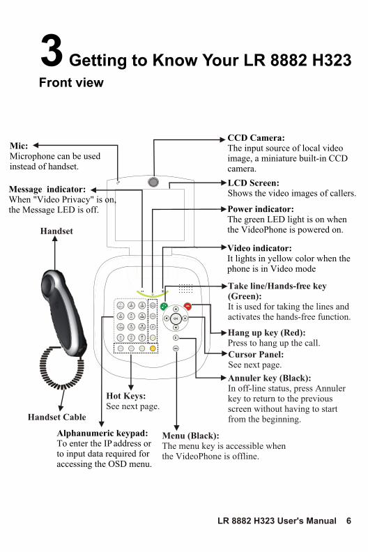
3 Getting to Know Your LR 8882 H323
Front view
Alphanumeric keypad:To enter the IP address or to input data required for accessing the OSD menu.
Video indicator:It lights in yellow color when the phone is in Video mode
Handset
Menu (Black):The menu key is accessible when the VideoPhone is offline.
Cursor Panel:See next page.
Hot Keys:See next page.
Annuler key (Black): In off-line status, press Annuler key to return to the previous screen without having to start from the beginning. Handset Cable
LCD Screen: Shows the video images of callers.
CCD Camera:The input source of local video image, a miniature built-in CCD camera.
Power indicator:The green LED light is on when the VideoPhone is powered on.
Hang up key (Red): Press to hang up the call.
Take line/Hands-free key(Green): It is used for taking the lines and activates the hands-free function.
LR 8882 H323 User's Manual 6
Mic: Microphone can be used instead of handset.
Message indicator:When "Video Privacy" is on, the Message LED is off.
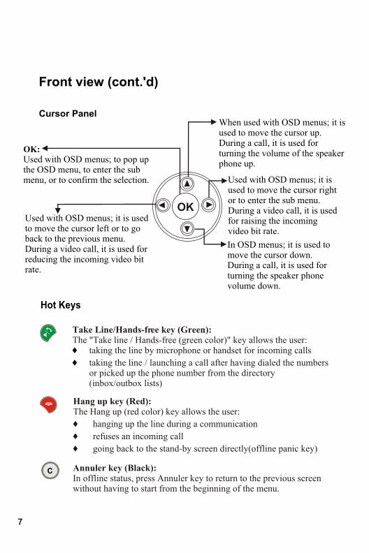
Front view (cont.'d)
Hot Keys
Used with OSD menus; it is used to move the cursor left or to go back to the previous menu. During a video call, it is used for reducing the incoming video bit rate.
OK: Used with OSD menus; to pop up the OSD menu, to enter the sub menu, or to confirm the selection. Used with OSD menus; it is
used to move the cursor right or to enter the sub menu. During a video call, it is used for raising the incoming video bit rate.
When used with OSD menus; it is used to move the cursor up. During a call, it is used for turning the volume of the speaker phone up.
In OSD menus; it is used to move the cursor down. During a call, it is used for turning the speaker phone volume down.
Cursor Panel
Take Line/Hands-free key (Green): The "Take line / Hands-free (green color)" key allows the user:
taking the line by microphone or handset for incoming calls
taking the line / launching a call after having dialed the numbers or picked up the phone number from the directory (inbox/outbox lists)
6
6
Hang up key (Red): The Hang up (red color) key allows the user:
6 hanging up the line during a communication
6 refuses an incoming call
6 going back to the stand-by screen directly(offline panic key)
Annuler key (Black): In offline status, press Annuler key to return to the previous screen without having to start from the beginning of the menu.
OK
7
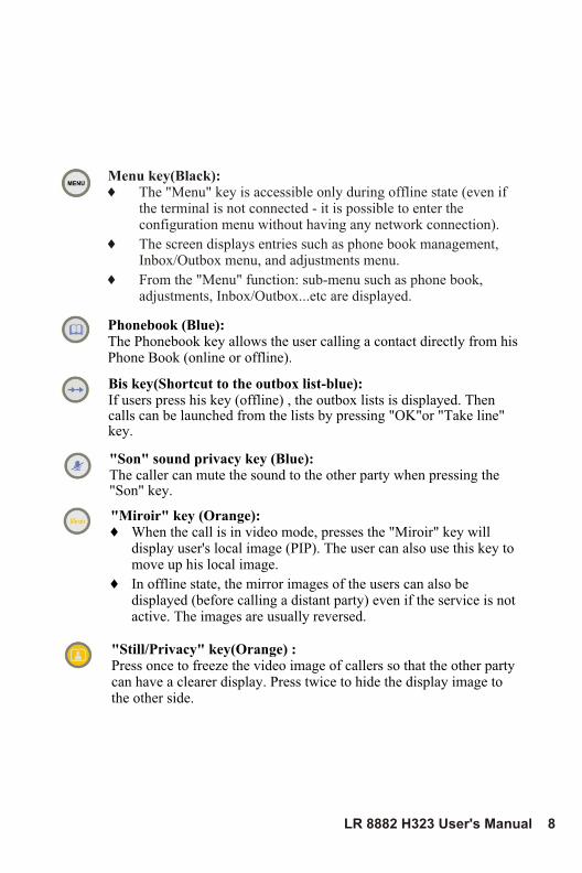
Phonebook (Blue):The Phonebook key allows the user calling a contact directly from his Phone Book (online or offline).
"Son" sound privacy key (Blue):The caller can mute the sound to the other party when pressing the "Son" key.
Bis key(Shortcut to the outbox list-blue):If users press his key (offline) , the outbox lists is displayed. Then calls can be launched from the lists by pressing "OK"or "Take line" key.
Menu key(Black):6 The "Menu" key is accessible only during offline state (even if
the terminal is not connected - it is possible to enter the configuration menu without having any network connection).
6 The screen displays entries such as phone book management, Inbox/Outbox menu, and adjustments menu.
6 From the "Menu" function: sub-menu such as phone book, adjustments, Inbox/Outbox...etc are displayed.
"Miroir" key (Orange): 6 When the call is in video mode, presses the "Miroir" key will
display user's local image (PIP). The user can also use this key to move up his local image.
6 In offline state, the mirror images of the users can also be displayed (before calling a distant party) even if the service is not active. The images are usually reversed.
LR 8882 H323 User's Manual 8
"Still/Privacy" key(Orange) :Press once to freeze the video image of callers so that the other party can have a clearer display. Press twice to hide the display image to the other side.
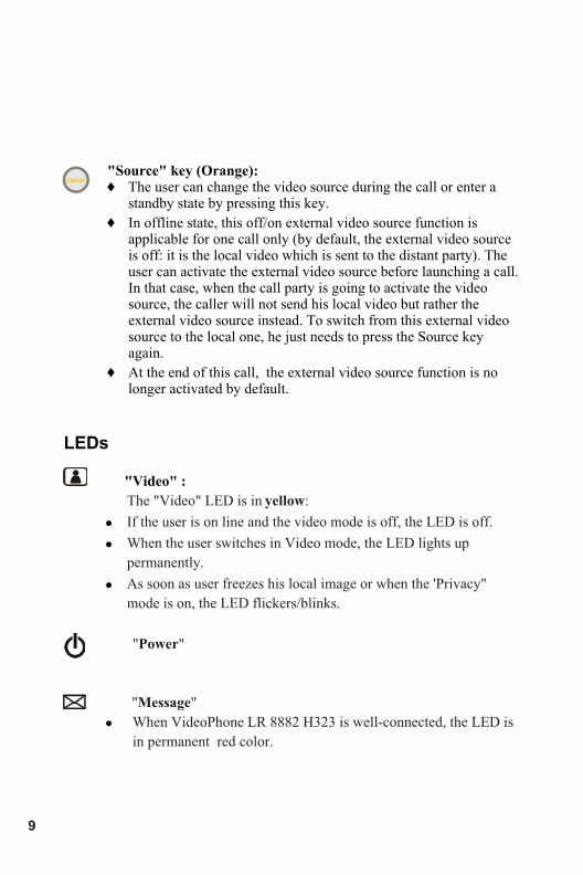
"Source" key (Orange): 6 The user can change the video source during the call or enter a
standby state by pressing this key.
6 In offline state, this off/on external video source function is applicable for one call only (by default, the external video source is off: it is the local video which is sent to the distant party). The user can activate the external video source before launching a call. In that case, when the call party is going to activate the video source, the caller will not send his local video but rather the external video source instead. To switch from this external video source to the local one, he just needs to press the Source key again.
6 At the end of this call, the external video source function is no longer activated by default.
9
LEDs
"Video" :
!
!
!
!
The "Video" LED is in yellow:
If the user is on line and the video mode is off, the LED is off.
When the user switches in Video mode, the LED lights up
permanently.
As soon as user freezes his local image or when the 'Privacy"
mode is on, the LED flickers/blinks.
"Power"
"Message"
When VideoPhone LR 8882 H323 is well-connected, the LED is
in permanent red color.
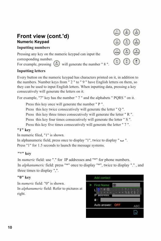
Numeric Keypad
Front view (cont.'d)
Inputting numbers
Pressing any key on the numeric keypad can input the
corresponding number.
For example, pressing will generate the number " 8 ".
Inputting letters
Every button on the numeric keypad has characters printed on it, in addition to the numbers. Number keys from " 2 " to " 9 " have English letters on them, so they can be used to input English letters. When inputting data, pressing a key consecutively will generate the letters on it.
For example, "7" key has the number " 7 " and the alphabets " PQRS " on it.
Press this key once will generate the number " P ".
Press this key twice consecutively will generate the letter " Q ".
Press this key three times consecutively will generate the letter " R ".
Press this key four times consecutively will generate the letter " S ".
Press this key five times consecutively will generate the letter " 7 ".
"1" key
In numeric filed, "1" is shown.
In alphanumeric field, press once to display "1", twice to display " ".
Press "1" for 1.5 seconds to launch the message systems.
"*" key
In numeric field: use "." for IP addresses and "*" for phone numbers.
In alphanumeric field: press "*" once to display "*", twice to display "." , and
three times to display ",".
"0" key
In numeric field: "0" is shown.
In alphanumeric field: Refer to pictures at
right.
10
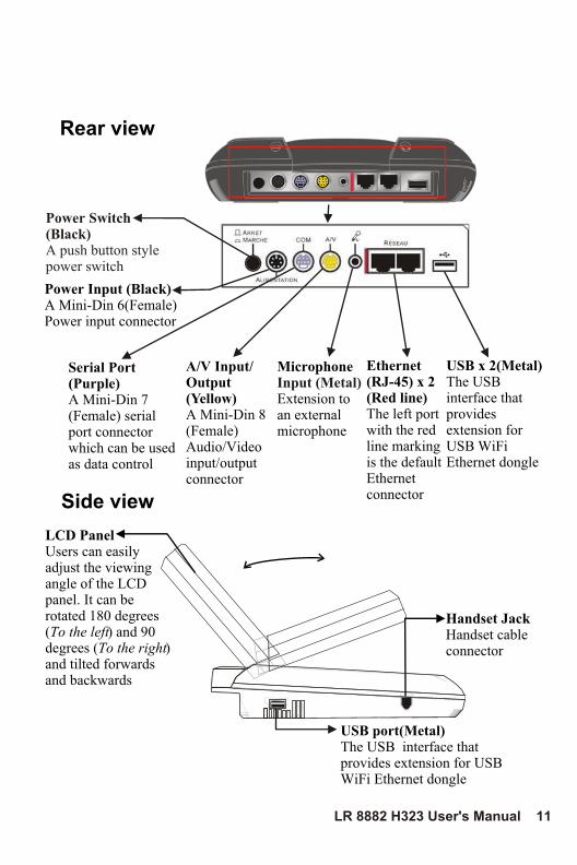
Rear view
Side view
LCD PanelUsers can easily adjust the viewing angle of the LCD panel. It can be rotated 180 degrees(To the left) and 90 degrees (To the right) and tilted forwards and backwards
Ethernet (RJ-45) x 2(Red line)The left port with the red line marking is the default Ethernet connector
Serial Port (Purple)A Mini-Din 7 (Female) serial port connector which can be used as data control
A/V Input/Output (Yellow) A Mini-Din 8 (Female)Audio/Video input/output connector
Microphone
Extension to an external microphone
Input (Metal)
Handset JackHandset cable connector
Power Switch(Black)A push button style power switch
Power Input (Black)A Mini-Din 6(Female)Power input connector
USB x 2(Metal)The USB interface that provides extension for USB WiFi Ethernet dongle
USB port(Metal)The USB interface that provides extension for USB WiFi Ethernet dongle
LR 8882 H323 User's Manual 11
4 Installation
Step 1 Pick a good spot
Prolonging the lifespanAvoid storing or operating LR 8882 H323 in abnormal conditions. High temperatures or excessive humidity could cause the unit to malfunction and shorten its useful lifespan.
StabilityPlace your LR 8882 H323 on top of a counter, desk, or table with the CCD camera opening in front.
Lighting conditionMake sure the lighting is sufficient and does not shine directly into camera lenses.
View of cameraAvoid using LR 8882 H323 in a room with brightly painted walls or flamboyant wallpaper. Soft and evenly painted background provides the best results.
Installing the unit
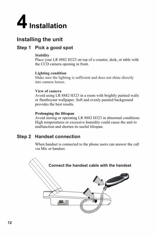
Step 2 Handset connection
When handset is connected to the phone users can answer the call via Mic or handset.
Connect the handset cable with the handset
12
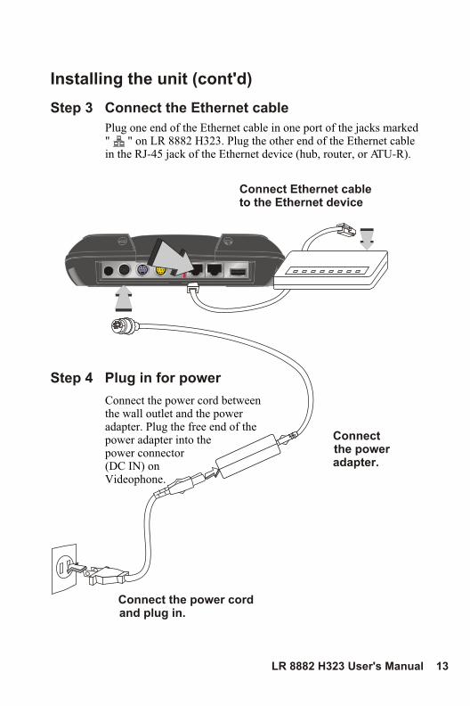
Installing the unit (cont'd)
Step 4 Plug in for power
Connect the power cord between the wall outlet and the power adapter. Plug the free end of the power adapter into the power connector (DC IN) on Videophone.
Connect the power adapter.
Connect the power cord and plug in.
Step 3 Connect the Ethernet cable
Plug one end of the Ethernet cable in one port of the jacks marked " " on LR 8882 H323. Plug the other end of the Ethernet cable in the RJ-45 jack of the Ethernet device (hub, router, or ATU-R).
Connect Ethernet cableto the Ethernet device
LR 8882 H323 User's Manual 13
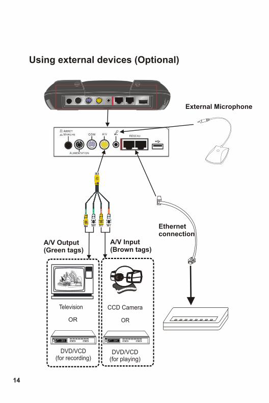
Using external devices (Optional)
OR
DVD/VCD (for recording)
Television
DVD/VCD (for playing)
OR
CCD Camera
Ethernet connection
External Microphone
A/V Output(Green tags)
A/V Input(Brown tags)
14
5 System Setup
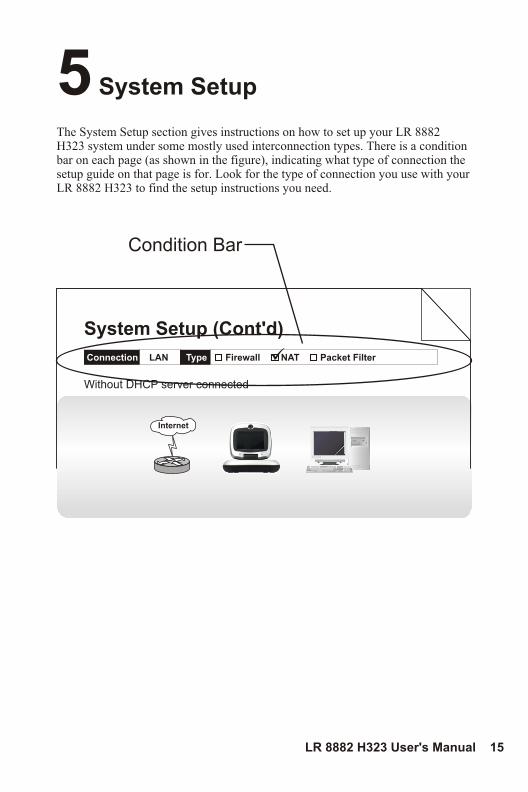
The System Setup section gives instructions on how to set up your LR 8882 H323 system under some mostly used interconnection types. There is a condition bar on each page (as shown in the figure), indicating what type of connection the setup guide on that page is for. Look for the type of connection you use with your LR 8882 H323 to find the setup instructions you need.
Connection LAN Type Firewall NAT Packet Filter
Without DHCP server connected
Internet
System Setup (Cont'd)
Condition Bar
LR 8882 H323 User's Manual 15
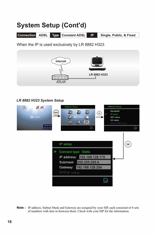
Connection ADSL Type Constant ADSL IP Single, Public, & Fixed
When the IP is used exclusively by LR 8882 H323
Internet
ATU-R
LR 8882 H323
System Setup (Cont'd)
16
Note : IP address, Subnet Mask and Gateway are assigned by your SIP, each consisted of 4 sets of numbers with dots in between them. Check with your ISP for the information.
LR 8882 H323 System Setup
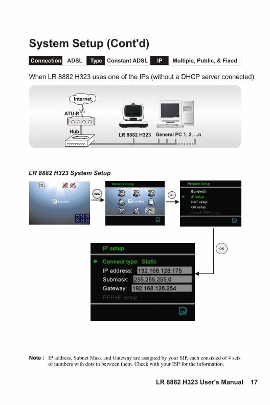
Connection ADSL Type Constant ADSL IP Multiple, Public, & Fixed
When LR 8882 H323 uses one of the IPs (without a DHCP server connected)
Internet
ATU-R
General PC 1, 2, ...nHub
System Setup (Cont'd)
LR 8882 H323
LR 8882 H323 User's Manual 17
Note : IP address, Subnet Mask and Gateway are assigned by your SIP, each consisted of 4 sets of numbers with dots in between them. Check with your ISP for the information.
LR 8882 H323 System Setup
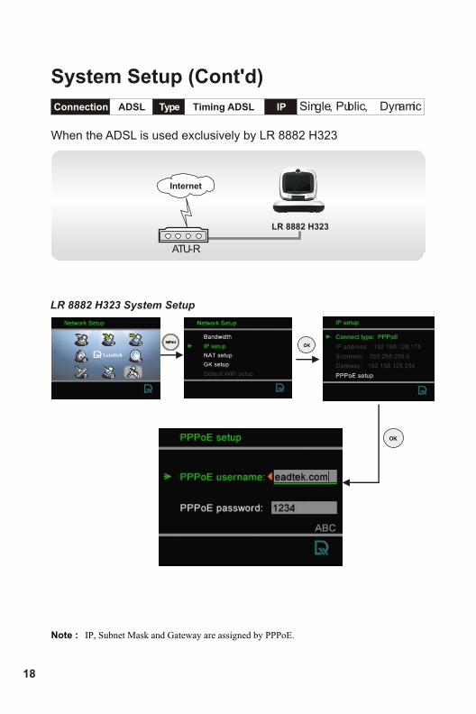
Connection ADSL Type Timing ADSL IP
When the ADSL is used exclusively by LR 8882 H323
Internet
ATU-R
Single, Public, & Dynamic
System Setup (Cont'd)
LR 8882 H323
18
Note : IP, Subnet Mask and Gateway are assigned by PPPoE.
LR 8882 H323 System Setup
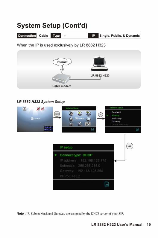
Connection Cable Type IP
When the IP is used exclusively by LR 8882 H323
Internet
Cable modem
-- Single, Public, & Dynamic
System Setup (Cont'd)
LR 8882 H323
LR 8882 H323 User's Manual 19
Note : IP, Subnet Mask and Gateway are assigned by the DHCP server of your SIP.
LR 8882 H323 System Setup
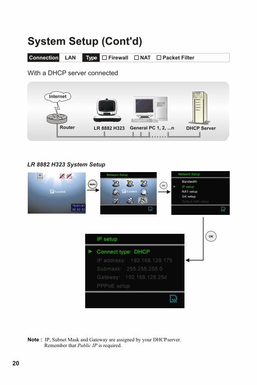
Connection LAN Type
Internet
Router
With a DHCP server connected
Firewall NAT Packet Filter
General PC 1, 2, ...n DHCP Server
System Setup (Cont'd)
LR 8882 H323
20
Note : IP, Subnet Mask and Gateway are assigned by your DHCP server. Remember that Public IP is required.
LR 8882 H323 System Setup
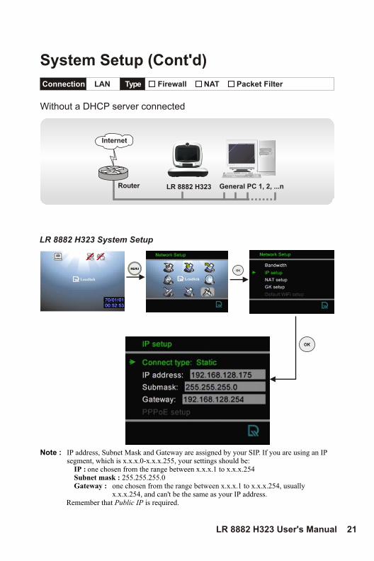
Connection LAN Type Firewall NAT Packet Filter
Without a DHCP server connected
Internet
Router General PC 1, 2, ...n
System Setup (Cont'd)
LR 8882 H323
LR 8882 H323 User's Manual 21
Note : IP address, Subnet Mask and Gateway are assigned by your SIP. If you are using an IP segment, which is x.x.x.0-x.x.x.255, your settings should be:
IP : one chosen from the range between x.x.x.1 to x.x.x.254Subnet mask : 255.255.255.0Gateway : one chosen from the range between x.x.x.1 to x.x.x.254, usually
x.x.x.254, and can't be the same as your IP address. Remember that Public IP is required.
LR 8882 H323 System Setup
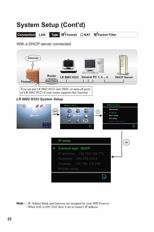
Connection LAN Type Firewall NAT Packet Filter
Internet
With a DHCP server connected
Router
Firewall
General PC 1, 2, ...n DHCP Server
You can put LR 8882 H323 into DMZ, or open all ports of LR 8882 H323 if your router supports this function.
System Setup (Cont'd)
LR 8882 H323
22
Note : - IP, Subnet Mask and Gateway are assigned by your DHCP server. - When NAT is ON, NAT door is set to router's IP address.
LR 8882 H323 System Setup

Connection LAN Type Firewall NAT Packet Filter
Without a DHCP server connected
Internet
Router
Firewall
General PC 1, 2, ...n
You can put LR 8882 H323 into DMZ, or open all ports of LR 8882 H323 if your router supports this function.
System Setup (Cont'd)
LR 8882 H323
LR 8882 H323 User's Manual 23
Note : IP address, Subnet Mask and Gateway are assigned by your SIP. If you are using an IP segment, which is x.x.x.0-x.x.x.255, your settings should be:
IP : one chosen from the range between x.x.x.1 to x.x.x.254Subnet mask : 255.255.255.0Gateway : one chosen from the range between x.x.x.1 to x.x.x.254, usually
x.x.x.254, and can't be the same as your IP address.
LR 8882 H323 System Setup
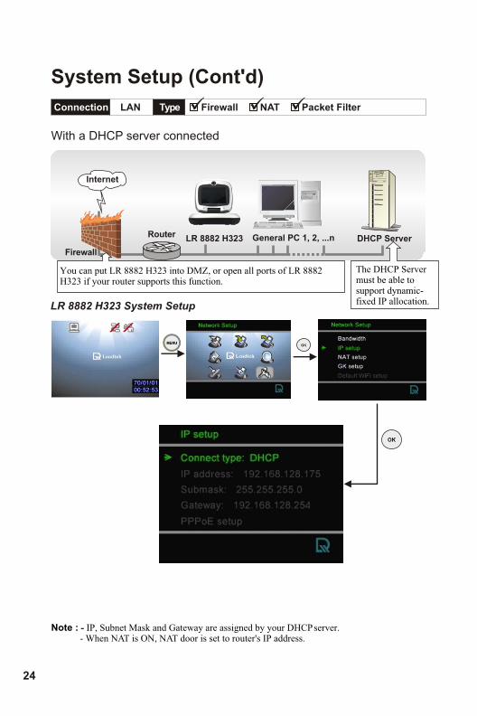
Connection LAN Type Firewall NAT Packet Filter
With a DHCP server connected
Internet
Router
Firewall
General PC 1, 2, ...n DHCP Server
The DHCP Server must be able to support dynamic-fixed IP allocation.
You can put LR 8882 H323 into DMZ, or open all ports of LR 8882 H323 if your router supports this function.
System Setup (Cont'd)
LR 8882 H323
24
Note : - IP, Subnet Mask and Gateway are assigned by your DHCP server. - When NAT is ON, NAT door is set to router's IP address.
LR 8882 H323 System Setup
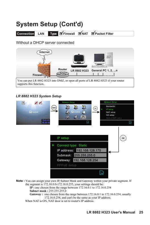
Connection LAN Type Firewall NAT Packet Filter
Without a DHCP server connected
Internet
Router
Firewall
General PC 1, 2, ...n
You can put LR 8882 H323 into DMZ, or open all ports of LR 8882 H323 if your router supports this function.
Note : You can assign your own IP, Subnet Mask and Gateway within your private segment. If the segment is 172.16.0.0-172.16.0.255, your settings should be:
IP : one chosen from the range between 172.16.0.1 to 172.16.0.254Subnet mask : 255.255.255.0Gateway : one chosen from the range between 172.16.0.1 to 172.16.0.254, usually
172.16.0.254, and can't be the same as your IP address. When NAT is ON, NAT door is set to router's IP address.
System Setup (Cont'd)
LR 8882 H323
LR 8882 H323 User's Manual 25
LR 8882 H323 System Setup
6 Making a Call
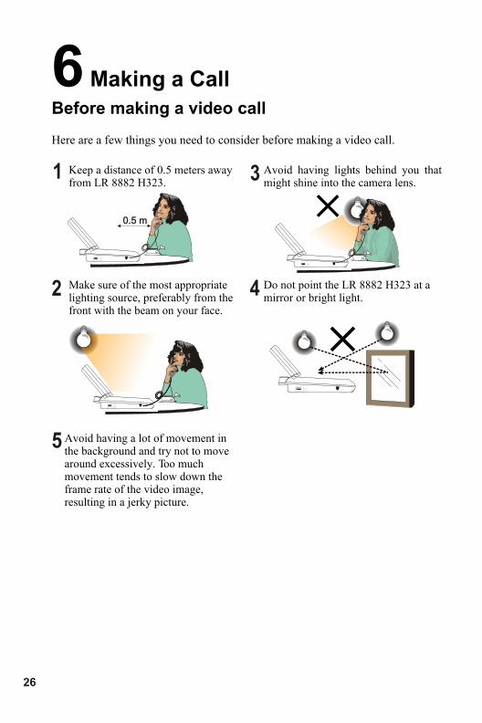
Before making a video call
Keep a distance of 0.5 meters away from LR 8882 H323.
Make sure of the most appropriate lighting source, preferably from the front with the beam on your face.
Avoid having lights behind you that might shine into the camera lens.
Do not point the LR 8882 H323 at a mirror or bright light.
Here are a few things you need to consider before making a video call.
Avoid having a lot of movement in the background and try not to move around excessively. Too much movement tends to slow down the frame rate of the video image, resulting in a jerky picture.
1
2
3
4
5
0.5 m0.5 m
26
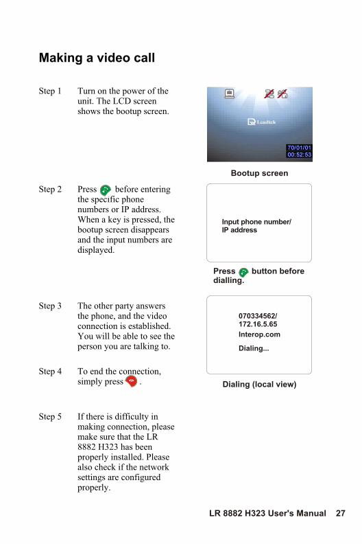
Step 1 Turn on the power of the unit. The LCD screen shows the bootup screen.
Step 2 Press before entering the specific phone numbers or IP address. When a key is pressed, the bootup screen disappears and the input numbers are displayed.
Step 3 The other party answers the phone, and the video connection is established. You will be able to see the person you are talking to.
Step 4 To end the connection, simply press .
Step 5 If there is difficulty in making connection, please make sure that the LR 8882 H323 has been properly installed. Please also check if the network settings are configured properly.
Making a video call
Bootup screen
Input phone number/IP address
Press button before dialling.
070334562/172.16.5.65
Interop.com
Dialing...
Dialing (local view)
LR 8882 H323 User's Manual 27
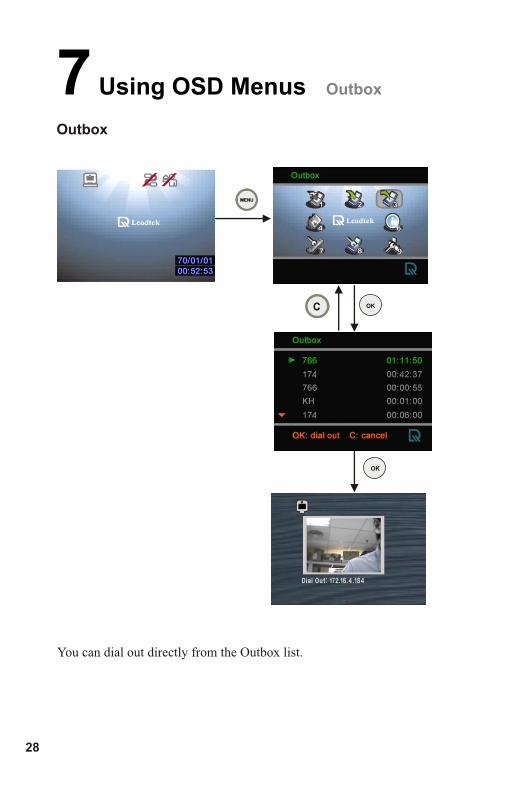
Outbox
7 Using OSD Menus
28
Outbox
You can dial out directly from the Outbox list.
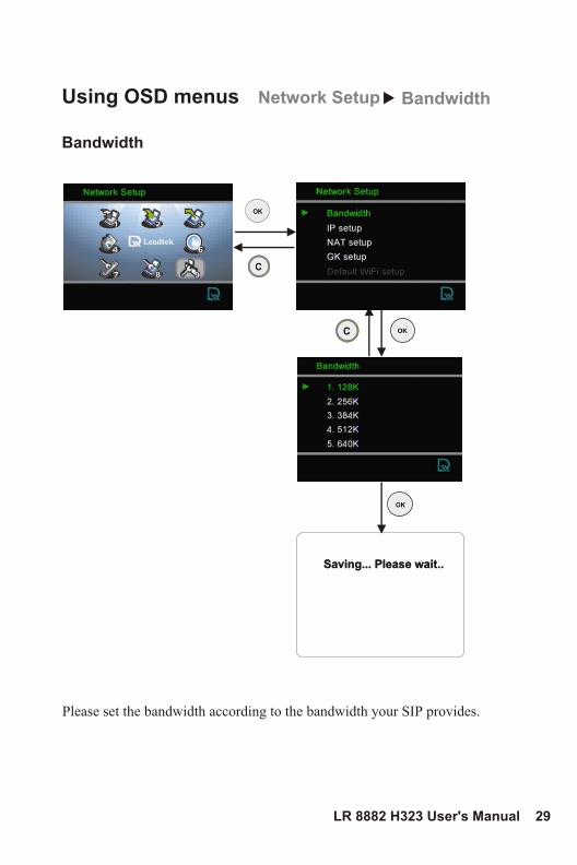
Using OSD menus
LR 8882 H323 User's Manual 29
Network Setup
Bandwidth
Please set the bandwidth according to the bandwidth your SIP provides.
Bandwidth
Saving... Please wait..Saving... Please wait..
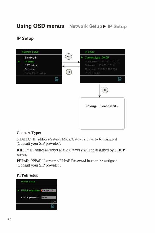
IP Setup
Using OSD menus
30
Network Setup
Connect Type:
STATIC: IP address/Subnet Mask/Gateway have to be assigned (Consult your SIP provider).
DHCP: .
PPPoE: PPPoE Username/PPPoE Password have to be assigned (Consult your SIP provider).
IP address/Subnet Mask/Gateway will be assigned by DHCP server
PPPoE setup:
IP Setup
Saving... Please wait..
NAT Setup
Using OSD menus
LR 8882 H323 User's Manual 31
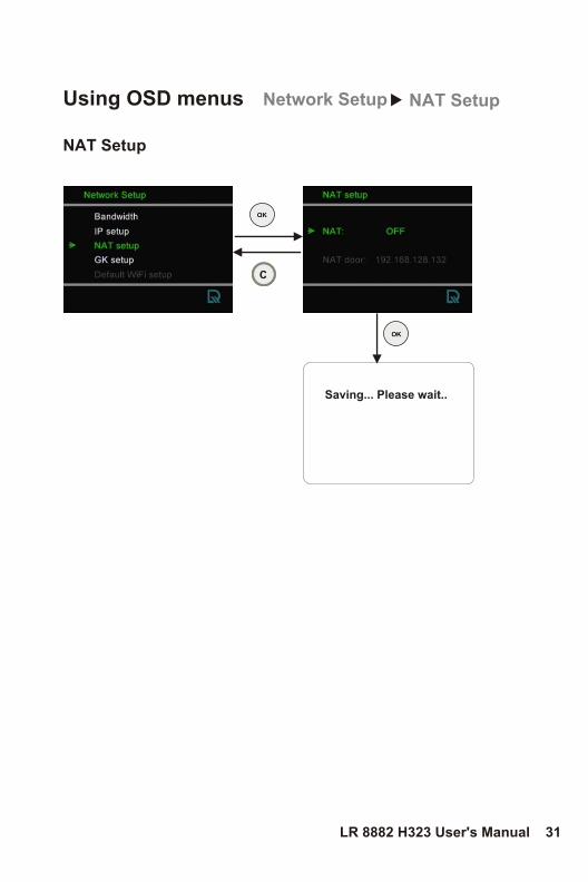
Network Setup NAT Setup
Saving... Please wait..
GK Setup
Using OSD menus
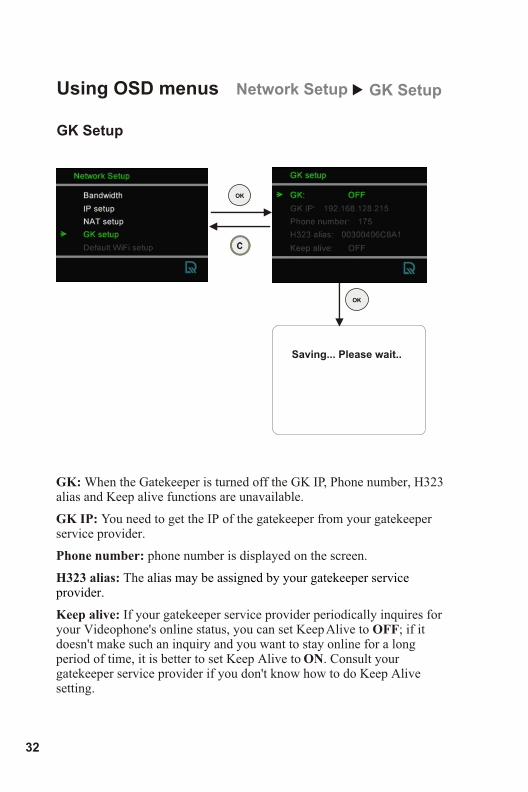
GK: When the Gatekeeper is turned off the GK IP, Phone number, H323 alias and Keep alive functions are unavailable.
GK IP: You need to get the IP of the gatekeeper from your gatekeeper service provider.
Phone number: phone number is displayed on the screen.
H323 alias: The
Keep alive: If your gatekeeper service provider periodically inquires for your Videophone's online status, you can set Keep Alive to OFF; if it doesn't make such an inquiry and you want to stay online for a long period of time, it is better to set Keep Alive to ON. Consult your gatekeeper service provider if you don't know how to do Keep Alive setting.
alias may be assigned by your gatekeeper service provider.
32
Network Setup GK Setup
Saving... Please wait..
Using OSD menus
LR 8882 H323 User's Manual 33
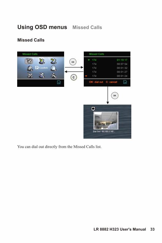
Missed Calls
Missed Calls
You can dial out directly from the Missed Calls list.
34
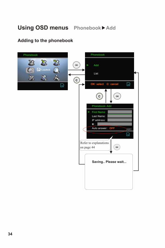
Using OSD menus Phonebook Add
Adding to the phonebook
Saving.. Please wait...
Refer to explanations
on page 44
LR 8882 H323 User's Manual 35
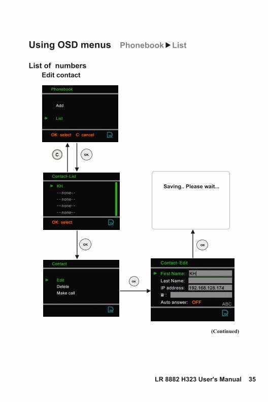
Using OSD menus Phonebook List
List of numbers
(Continued)
Saving.. Please wait...
Edit contact
36
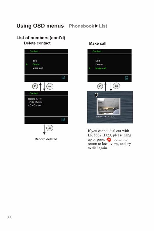
Using OSD menus
List of numbers (cont'd) Delete contact
Phonebook List
If you cannot dial out with LR 8882 H323, please hang up or press button to return to local view, and try to dial again.
Make call
Record deleted
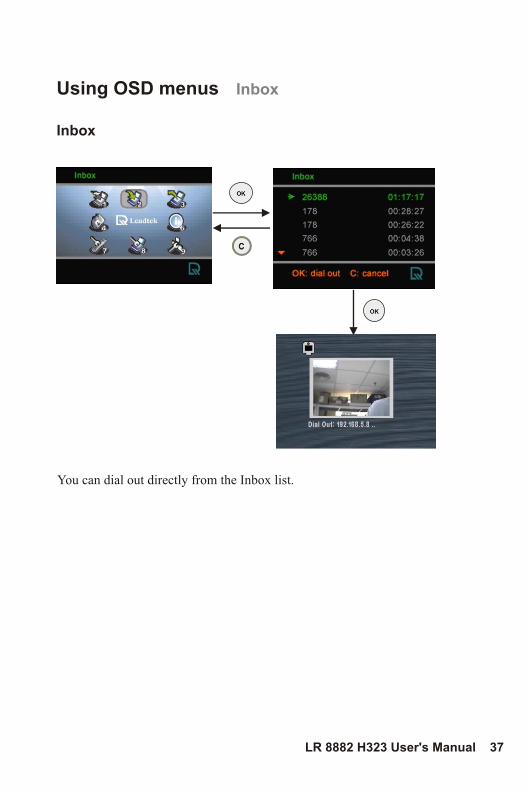
Inbox
Using OSD menus Inbox
LR 8882 H323 User's Manual 37
You can dial out directly from the Inbox list.
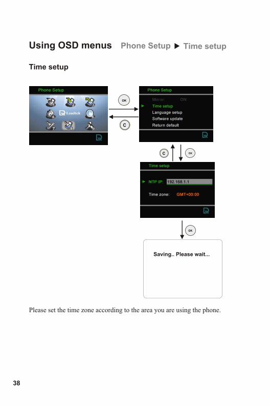
Time setup
Using OSD menus Phone Setup Time setup
Please set the time zone according to the area you are using the phone.
Saving.. Please wait...
38
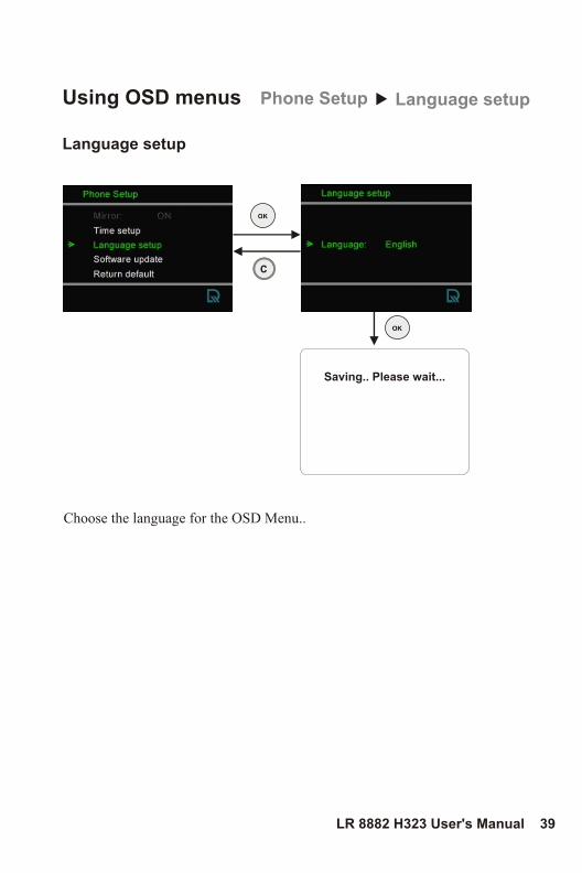
Language setup
Using OSD menus Phone Setup Language setup
Choose the language for the OSD Menu..
Saving.. Please wait...
LR 8882 H323 User's Manual 39
4040
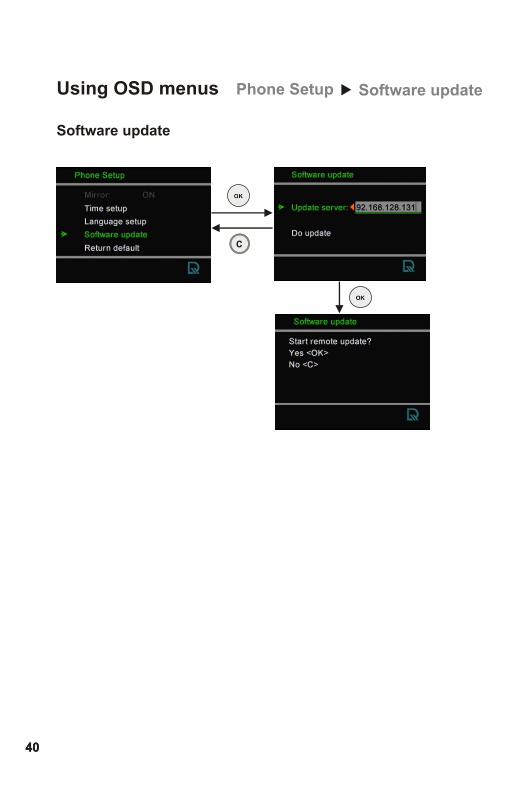
Using OSD menus Phone Setup Software update
Software update
LR 8882 H323 User's Manual 41
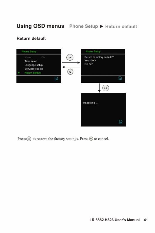
Return default
Using OSD menus Phone Setup Return default
Press to restore the factory settings. Press to cancel.
42
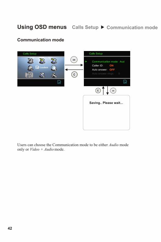
Communication mode
Using OSD menus Calls Setup Communication mode
Saving.. Please wait...
Users can choose the Communication mode to be either Audio mode only or Video + Audio mode.
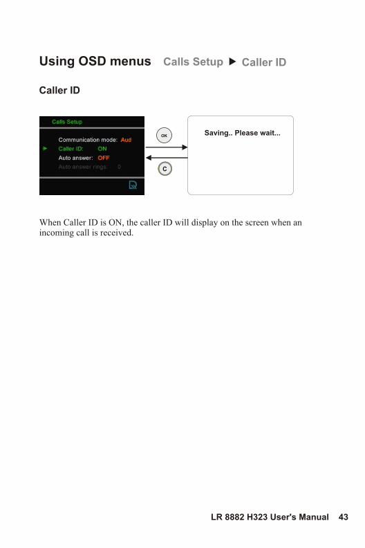
Caller ID
Using OSD menus Calls Setup Caller ID
When Caller ID is ON, the caller ID will display on the screen when an incoming call is received.
Saving.. Please wait...
LR 8882 H323 User's Manual 43
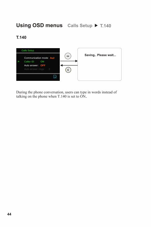
T.140
Using OSD menus Calls Setup T.140
During the phone conversation, when T.140 is set to ON.
users can type in words instead of talking on the phone .
Saving.. Please wait...
44
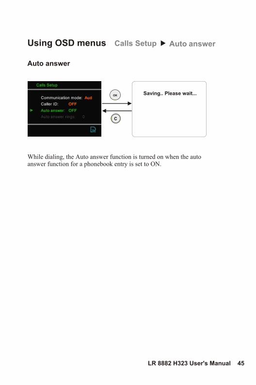
Auto answer
Using OSD menus Calls Setup Auto answer
While dialing, the Auto answer function is turned on when the auto answer function for a phonebook entry is set to ON.
Saving.. Please wait...
LR 8882 H323 User's Manual 45
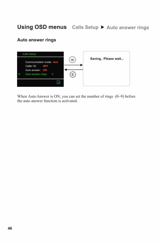
Auto answer rings
Using OSD menus Calls Setup Auto answer rings
When Auto Answer is ON, you can set the number of rings (0~9) before the auto answer function is activated.
Saving.. Please wait...
46
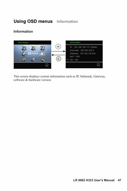
Using OSD menus Information
Information
Using OSD menus
This screen displays system information such as IP, Submask, Gateway, software & hardware version.
LR 8882 H323 User's Manual 47
Phonebook
Information
Calls Setup
Network Setup
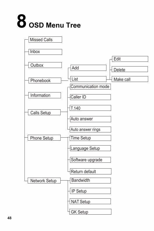
8 OSD Menu Tree
Phone Setup
Inbox
Outbox
IP Setup
GK Setup
Missed Calls
Add
List
Edit
Delete
Make call
NAT Setup
48
Communication mode
Caller ID
Auto answer
Auto answer rings
T.140
Bandwidth
Return default
Software upgrade
Language Setup
Time Setup
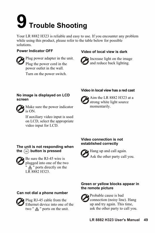
Make sure the power indicator is ON.
If auxiliary video input is used on LCD, select the appropriate video input for LCD.
No image is displayed on LCD screen
Increase light on the image and reduce back lighting.
Video of local view is dark
Aim the LR 8882 H323 at a strong white light source momentarily.
Video in local view has a red cast
Hang up and call again.
Ask the other party call you.
Video connection is not established correctly
Probable cause is bad connection (noisy line). Hang up and try again. This time, ask the other party to call you.
Green or yellow blocks appear in the remote picture
Your LR 8882 H323 is reliable and easy to use. If you encounter any problem while using this product, please refer to the table below for possible solutions.
Plug power adapter in the unit.
Plug the power cord in the power outlet in the wall.
Turn on the power switch.
Power Indicator OFF
The unit is not responding when the button is pressed
Be sure the RJ-45 wire is plugged into one of the two" " ports directly on the LR 8882 H323.
Can not dial a phone number
Plug RJ-45 cable from the Ethernet device into one of the two " " ports on the unit.
9 Trouble Shooting
LR 8882 H323 User's Manual 49
In the event of not finding the solution to your problem, please contact your local distributor. You may also contact our technical support staff; E-mail to <[email protected]> with the following information:
Product name:It will be easier for our staff to answer your question if you know the name of the product.
Detailed description of your problem:Please describe in detail all the problems you encountered, including the kind of software and hardware you are using, and the contents of your system files.
10 Tech Support
50

Leadtek warrants to the original purchaser of this product that it shall be free of defects resulting from workmanship or components for a period of one (1) year from the date of sale. Defects covered by this Limited Warranty shall be corrected either by repair or, at Leadtek's discretion by replacement. In the event of replacement, the replacement unit will be warranted for the remainder of the original one (1) year period or thirty (30) days, whichever is longer. THERE ARE NO OTHER ORAL OR WRITTEN WARRANTIES, EXPRESSED OR IMPLIED, INCLUDING BUT NOT LIMITED TO THOSE OF MERCHANTABILITY OR FITNESS FOR A PARTICULAR PURPOSE.
This Limited Warranty is nontransferable and does not apply if the product has been damaged by negligence, accident, abuse, misuse, modification, misapplication, shipment to the Manufacturer or service by someone other than the Leadtek Transportation charges to Leadtek are not covered by this Limited Warranty. To be eligible for warranty service, a defective product must be sent to and received by Leadtek within fourteen (14) months of the date of sale and be accompanied with proof of purchase. Leadtek does not warrant that this product will meet your requirements; it is your sole responsibility to determine the suitability of this product for your purposes. Leadtek does not warrant the compatibility of this product with your computer or related peripherals, software.
LEADTEK'S SOLE OBLIGATION AND LIABILITY UNDER THIS WARRANTY IS LIMITED TO THE REPAIR OR REPLACEMENT OF A DEFECTIVE PRODUCT. THE MANUFACTURER SHALL NOT, IN ANY EVENT, BE LIABLE TO THE PURCHASER OR ANY THIRD PARTY FOR ANY INCIDENTAL OR CONSEQUENTIAL DAMAGES OR LIABILITY IN TORT RELATING TO THIS PRODUCT OR RESULTING FROM ITS USE OR POSSESSION.
11 Limited Warranty
LR 8882 H323 User's Manual 51
12 FCC Statement
This device complies with Part 15 of the FCC Rules. Operation is subject to the following two conditions:
· This device may not cause harmful interference.
· This device must accept any interference received, including interference that may cause undesired operation.
This equipment has been tested and found to comply with the limits for a Class B digital device pursuant to Part 15 of FCC Rules. These limits are designed to provide reasonable protection against harmful interference in a residential installation. This equipment generates, uses and can radiate radio frequency energy and, if not installed and used in accordance with the instructions, may cause harmful interference to radio communications. However, there is no guarantee that interference will not occur in a particular installation. If this equipment does cause harmful interference to radio or television reception, which can be determined by turning the equipment off and on, the user is encouraged to try to correct the interference by one or more of the following measures:
· Reorient or relocate the receiving antenna.
· Increase the separation between the equipment and receiver.
· Connect the equipment into an outlet on a circuit different from that to which the receiver is connected.
· Consult the dealer or an experienced radio/TV technician for help.
· Shielded interface cables must be used in order to comply with emission limits. Changes or modifications not expressly approved by the party responsible for compliance could void the user's authority to operate the equipment.
50