Embed Size (px)
Citation preview
1 | 4G Wireless | Teck Hu
LTE-Advanced & Heterogeneous Networks •Long Term Evolution – 4G Wireless Communications
Teck Hu
Wireless Core Technology

2 | 4G Wireless | Teck Hu
Outline
Introduction to 3G and 4G
3GPP Standardization Process
Wireless Challenges and LTE
Review of Wireless Communications
Technologies in LTE
LTE-Advanced
Objectives & Requirements
Overview of LTE-Advanced
Beyond LTE Advanced
3 | 4G Wireless | Teck Hu
Introduction to 3G and 4G
4 | 4G Wireless | Teck Hu
Key Trends in 3GPP Standardization
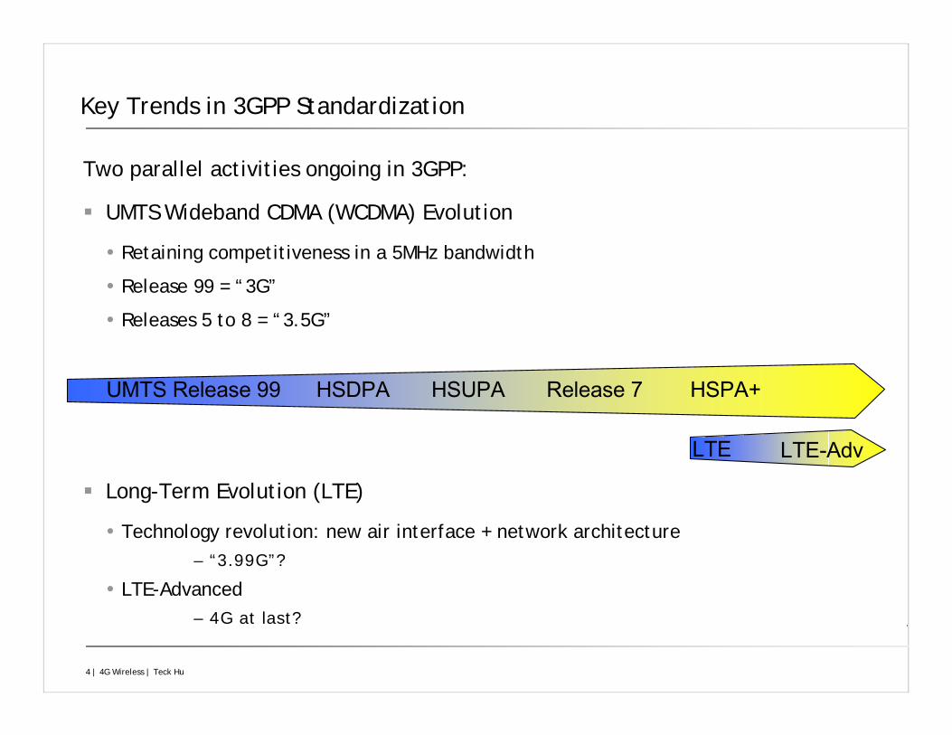
Two parallel activities ongoing in 3GPP:
UMTS Wideband CDMA (WCDMA) Evolution
Retaining competitiveness in a 5MHz bandwidth
Release 99 = “3G”
Releases 5 to 8 = “3.5G”
Long-Term Evolution (LTE)
Technology revolution: new air interface + network architecture– “3.99G”?
LTE-Advanced– 4G at last?
UMTS Release 99 HSDPA HSUPA Release 7 HSPA+
LTE LTE-Adv
5 | 4G Wireless | Teck Hu
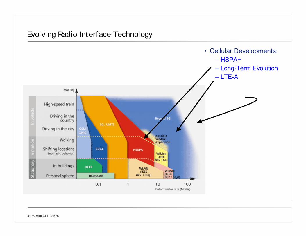
Evolving Radio Interface Technology
• Cellular Developments:– HSPA+– Long-Term Evolution– LTE-A
6 | 4G Wireless | Teck Hu
LTE Timeline
Inauguration Workshop November 2004
Requirements were finalised 3rd June 2005
Outline concept-descriptions agreed 21st June 2005
Multiple-Access Schemes (UL and DL) chosen in Dec 2005
Study phase closed in Sept 2006
Evaluation of key techniques for LTE complete
Detailed specification work began in Oct 2006
First Release of LTE Specifications is Release 8.
Specifications virtually complete at end of 2008
First deployment December 2009
A new system, developed in parallel with WCDMA evolution
A revolution in the Radio Access Network
A stepping-stone to a “4G” air interfac
Enables Operators to restructure their networks in preparation for 4G
7 | 4G Wireless | Teck Hu
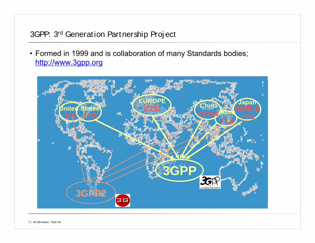
3GPP: 3rd Generation Partnership Project
• Formed in 1999 and is collaboration of many Standards bodies; http://www.3gpp.org
3GPP
EUROPEKore
a
JapanChinaETSITIA
TTACCSA
ARIB & TTC
3GPP2
United StatesATIS
8 | 4G Wireless | Teck Hu
The Role of Standards
Interoperability
Facilitates control of access to spectrum
Economies of scale
Transcends national boundaries
Generates new markets
Low barrier to entry promotes competition
Disadvantages
Potentially slow
IPR issues
9 | 4G Wireless | Teck Hu
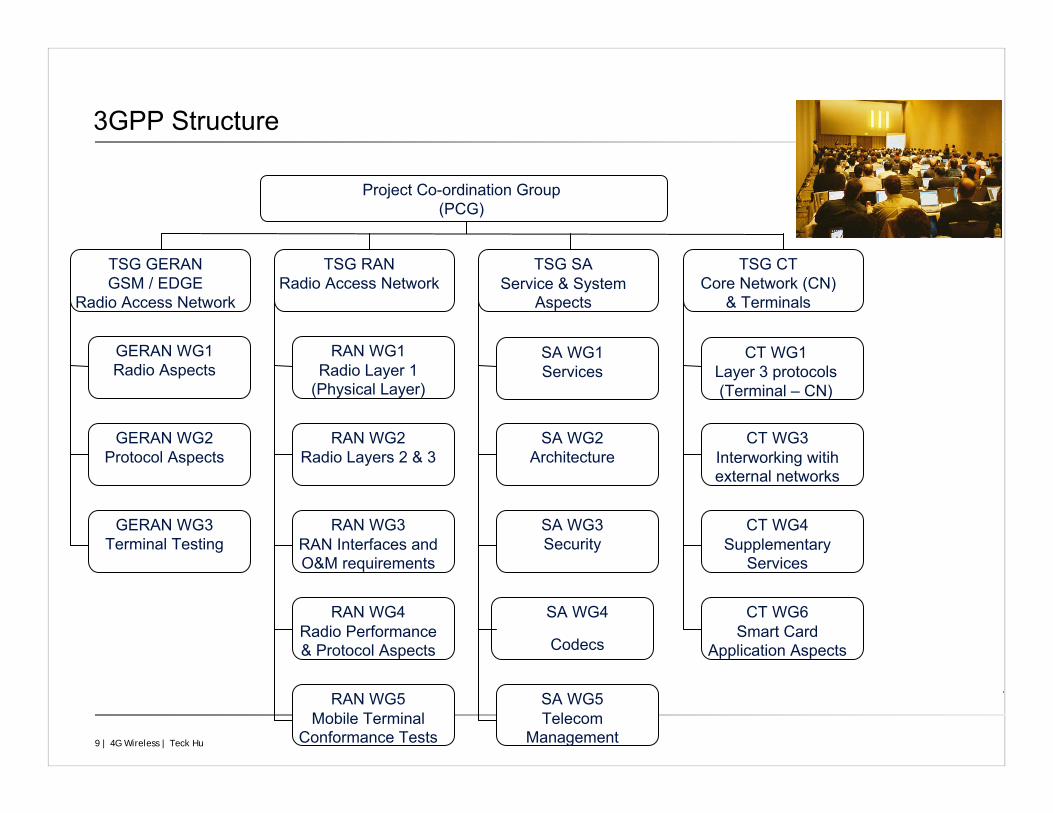
3GPP Structure
Project Co-ordination Group(PCG)
TSG GERANGSM / EDGE
Radio Access Network
TSG RANRadio Access Network
TSG SAService & System
Aspects
TSG CTCore Network (CN)
& Terminals
GERAN WG1Radio Aspects
GERAN WG2Protocol Aspects
GERAN WG3Terminal Testing
RAN WG1Radio Layer 1
(Physical Layer)
RAN WG2Radio Layers 2 & 3
RAN WG3RAN Interfaces and O&M requirements
RAN WG4Radio Performance & Protocol Aspects
RAN WG5Mobile Terminal
Conformance Tests
SA WG1Services
SA WG2Architecture
SA WG3Security
SA WG4
Codecs
SA WG5Telecom
Management
CT WG1Layer 3 protocols(Terminal – CN)
CT WG3Interworking witihexternal networks
CT WG4Supplementary
Services
CT WG6Smart Card
Application Aspects
10 | 4G Wireless | Teck Hu
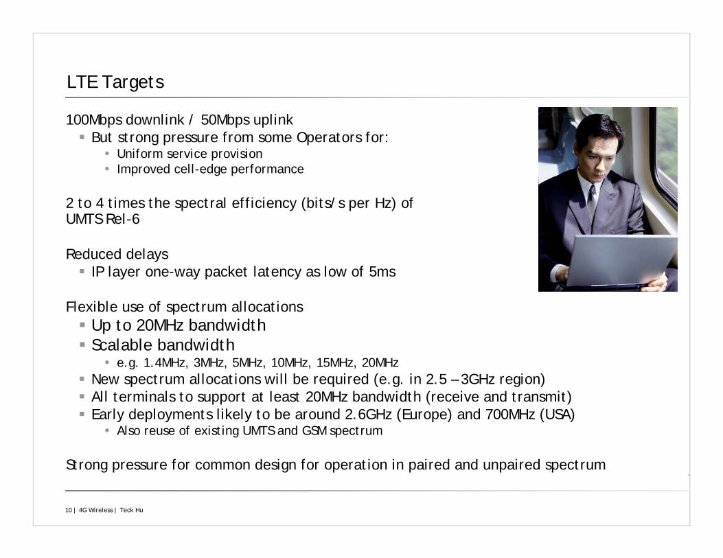
LTE Targets
100Mbps downlink / 50Mbps uplinkBut strong pressure from some Operators for:
Uniform service provisionImproved cell-edge performance
2 to 4 times the spectral efficiency (bits/s per Hz) of UMTS Rel-6
Reduced delays IP layer one-way packet latency as low of 5ms
Flexible use of spectrum allocationsUp to 20MHz bandwidthScalable bandwidth
e.g. 1.4MHz, 3MHz, 5MHz, 10MHz, 15MHz, 20MHzNew spectrum allocations will be required (e.g. in 2.5 – 3GHz region)All terminals to support at least 20MHz bandwidth (receive and transmit)Early deployments likely to be around 2.6GHz (Europe) and 700MHz (USA)
Also reuse of existing UMTS and GSM spectrum
Strong pressure for common design for operation in paired and unpaired spectrum
11 | 4G Wireless | Teck Hu
Application Trends for LTE
The following are enabled by 3.5G, and greatly enhanced by LTE:
Growth in Packet Data traffic
E-mail, Web-browsing, Photos and Videos, Interactive gaming
Voice moving to packet-switching: VoIP
Reduced costs for Operators
Broadcast services
Business case not yet established
DVB-H already available in some terminals
But few cellular Operators own spectrum for DVB-H
Hence interest in cellular broadcastMBMS (Multimedia Broadcast / Multicast Service)
Quality may be lower than DVB-H, but cheaper for Operators and enables Operators to retain control
Not in first release of LTE
12 | 4G Wireless | Teck Hu
Wireless Challenges and LTE
13 | 4G Wireless | Teck Hu
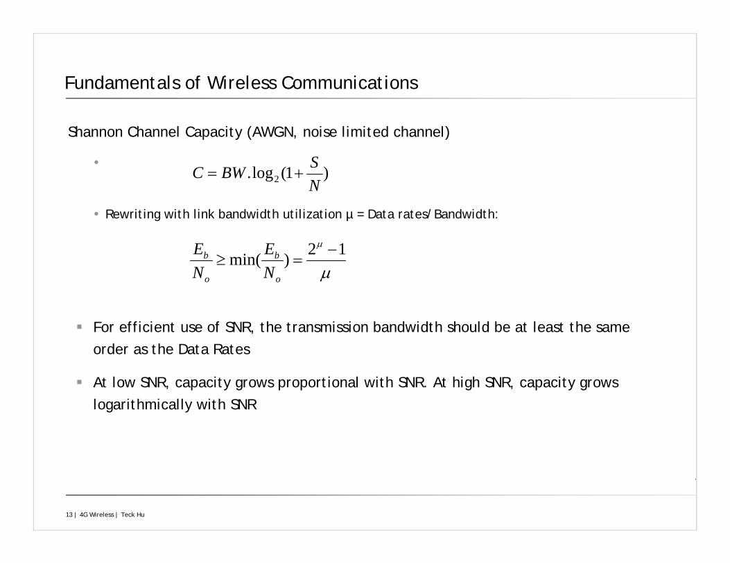
Fundamentals of Wireless Communications
Shannon Channel Capacity (AWGN, noise limited channel)
Rewriting with link bandwidth utilization µ = Data rates/Bandwidth:
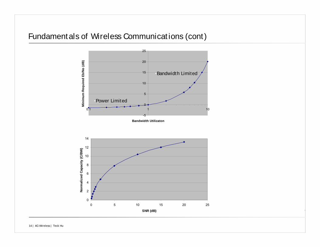
For efficient use of SNR, the transmission bandwidth should be at least the same order as the Data Rates
At low SNR, capacity grows proportional with SNR. At high SNR, capacity grows logarithmically with SNR
)1(log. 2 NSBWC +=
μ
μ 12)min( −=≥
o
b
o
b
NE
NE
14 | 4G Wireless | Teck Hu
Fundamentals of Wireless Communications (cont)
-5
0
5
10
15
20
25
0.1 1 10
Bandwidth Utilizaton
Min
imum
Req
uire
d Eb
/No
(dB
)
•Bandwidth Limited
•Power Limited
0
2
4
6
8
10
12
14
0 5 10 15 20 25
SNR (dB)
Norm
aliz
ed C
apac
ity (C
/BW
)
15 | 4G Wireless | Teck Hu
Operating Regions and Trade-Offs
If required SNR is available, any data rate can be in theory be achieved
Any increase in Data Rate will require at least the same relative increase in SNR. Two regions can be viewed: power limited and bandwidth limited.
Power Limited Region
E.g. Mobile at Cell edge or when low bandwidth utilization
Solution: Increase the received power: Beamforming technique, reduced cell size, Receive Combining
Bandwidth Limited Region
E.g. Mobile close to BS or in Small Cell
Any increase of bandwidth will reduce the required SNR for a certain data rate
Solution: Improved the spectral efficiency of the technique: reduced the required Eb/No per bit/s: Spatial multiplexing, Diversity
16 | 4G Wireless | Teck Hu
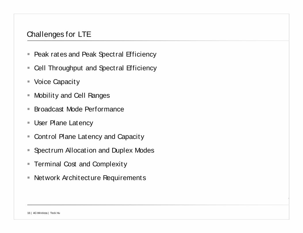
Challenges for LTE
Peak rates and Peak Spectral Efficiency
Cell Throughput and Spectral Efficiency
Voice Capacity
Mobility and Cell Ranges
Broadcast Mode Performance
User Plane Latency
Control Plane Latency and Capacity
Spectrum Allocation and Duplex Modes
Terminal Cost and Complexity
Network Architecture Requirements
17 | 4G Wireless | Teck Hu
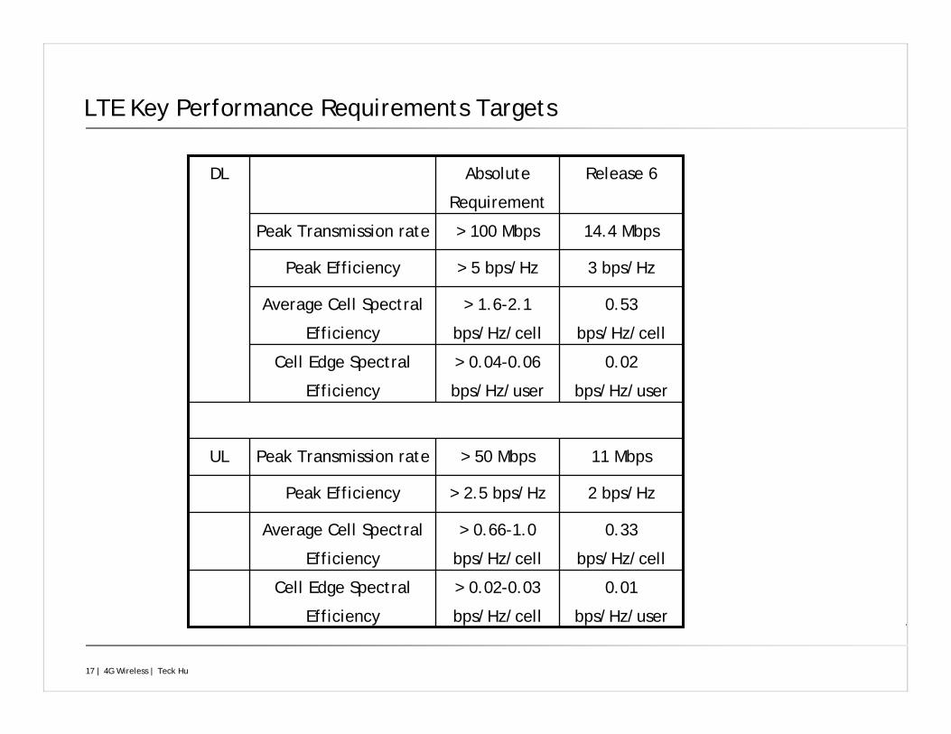
LTE Key Performance Requirements Targets
0.01
bps/Hz/user
> 0.02-0.03
bps/Hz/cell
Cell Edge Spectral
Efficiency
0.33
bps/Hz/cell
> 0.66-1.0
bps/Hz/cell
Average Cell Spectral
Efficiency
2 bps/Hz> 2.5 bps/HzPeak Efficiency
11 Mbps> 50 MbpsPeak Transmission rateUL
0.02
bps/Hz/user
> 0.04-0.06
bps/Hz/user
Cell Edge Spectral
Efficiency
0.53
bps/Hz/cell
> 1.6-2.1
bps/Hz/cell
Average Cell Spectral
Efficiency
3 bps/Hz> 5 bps/HzPeak Efficiency
14.4 Mbps> 100 MbpsPeak Transmission rate
Release 6Absolute
Requirement
DL
18 | 4G Wireless | Teck Hu
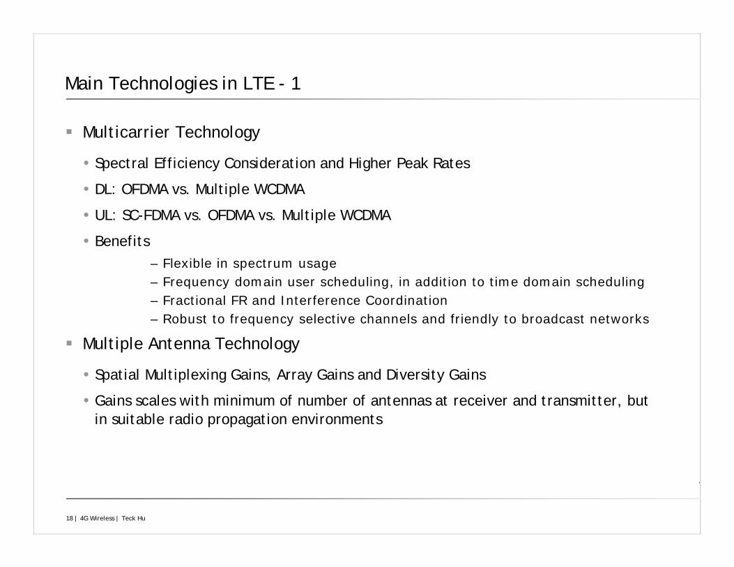
Main Technologies in LTE - 1
Multicarrier Technology
Spectral Efficiency Consideration and Higher Peak Rates
DL: OFDMA vs. Multiple WCDMA
UL: SC-FDMA vs. OFDMA vs. Multiple WCDMA
Benefits– Flexible in spectrum usage– Frequency domain user scheduling, in addition to time domain scheduling– Fractional FR and Interference Coordination– Robust to frequency selective channels and friendly to broadcast networks
Multiple Antenna Technology
Spatial Multiplexing Gains, Array Gains and Diversity Gains
Gains scales with minimum of number of antennas at receiver and transmitter, but in suitable radio propagation environments
19 | 4G Wireless | Teck Hu
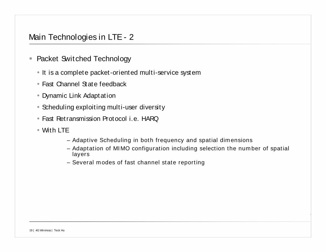
Main Technologies in LTE - 2
Packet Switched Technology
It is a complete packet-oriented multi-service system
Fast Channel State feedback
Dynamic Link Adaptation
Scheduling exploiting multi-user diversity
Fast Retransmission Protocol i.e. HARQ
With LTE– Adaptive Scheduling in both frequency and spatial dimensions– Adaptation of MIMO configuration including selection the number of spatial
layers– Several modes of fast channel state reporting
20 | 4G Wireless | Teck Hu
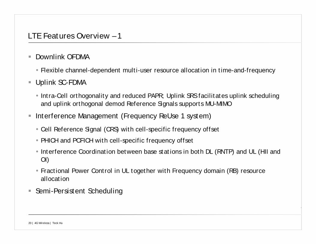
LTE Features Overview – 1
Downlink OFDMA
Flexible channel-dependent multi-user resource allocation in time-and-frequency
Uplink SC-FDMA
Intra-Cell orthogonality and reduced PAPR; Uplink SRS facilitates uplink scheduling and uplink orthogonal demod Reference Signals supports MU-MIMO
Interference Management (Frequency ReUse 1 system)
Cell Reference Signal (CRS) with cell-specific frequency offset
PHICH and PCFICH with cell-specific frequency offset
Interference Coordination between base stations in both DL (RNTP) and UL (HII and OI)
Fractional Power Control in UL together with Frequency domain (RB) resource allocation
Semi-Persistent Scheduling
21 | 4G Wireless | Teck Hu
LTE Features Overview – 2
Downlink Spatial Multiplexing and Diversity
Uplink Multi-User MIMO
Multi-User and Adaptive Retransmission
Short frame duration (1ms) for low HARQ RTT
22 | 4G Wireless | Teck Hu
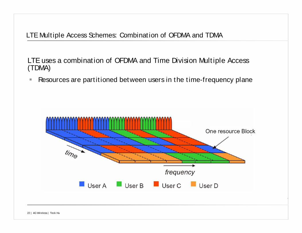
LTE uses a combination of OFDMA and Time Division Multiple Access (TDMA)
Resources are partitioned between users in the time-frequency plane
LTE Multiple Access Schemes: Combination of OFDMA and TDMA
23 | 4G Wireless | Teck Hu
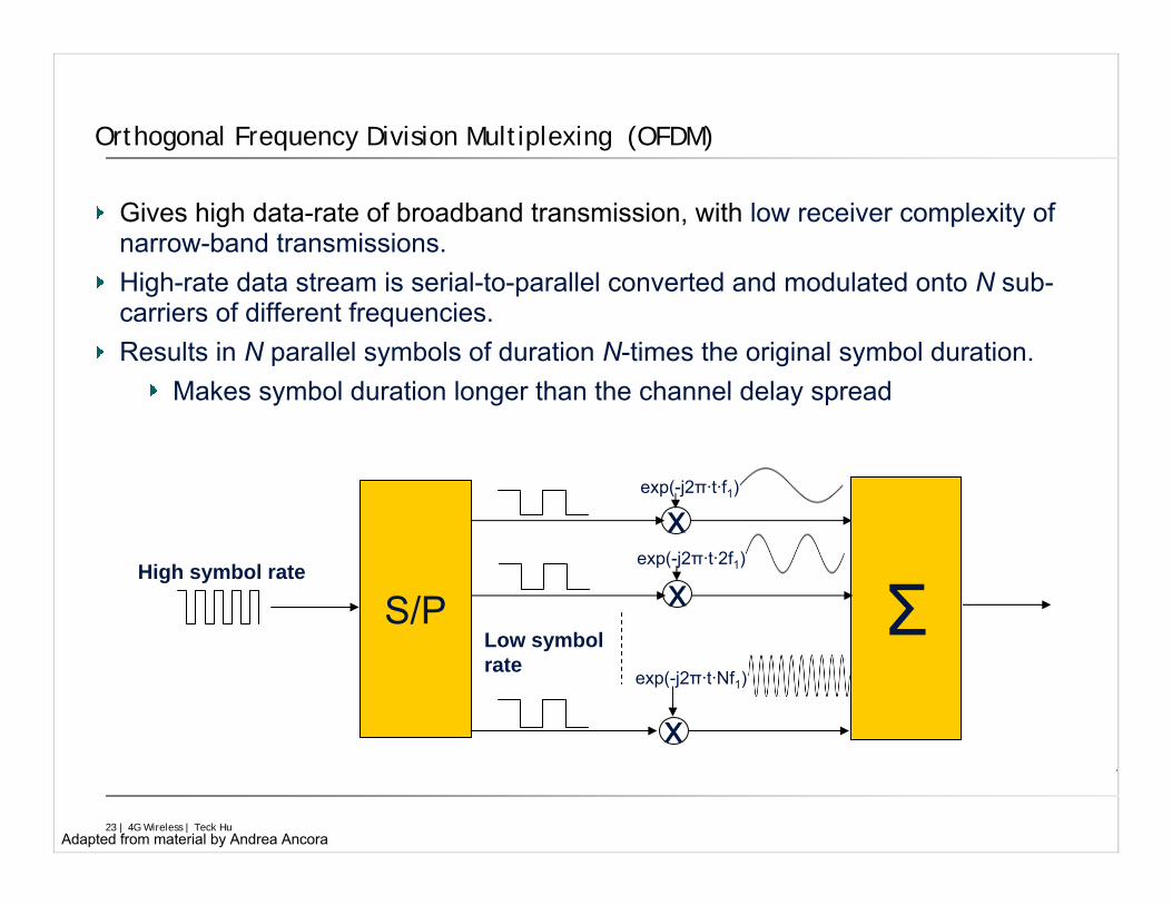
Gives high data-rate of broadband transmission, with low receiver complexity of narrow-band transmissions.High-rate data stream is serial-to-parallel converted and modulated onto N sub-carriers of different frequencies.Results in N parallel symbols of duration N-times the original symbol duration.
Makes symbol duration longer than the channel delay spread
Orthogonal Frequency Division Multiplexing (OFDM)
S/P
x
x
Σ
exp(-j2π·t·f1)
exp(-j2π·t·Nf1)
High symbol rate
Low symbol rate
xexp(-j2π·t·2f1)
Adapted from material by Andrea Ancora
24 | 4G Wireless | Teck Hu
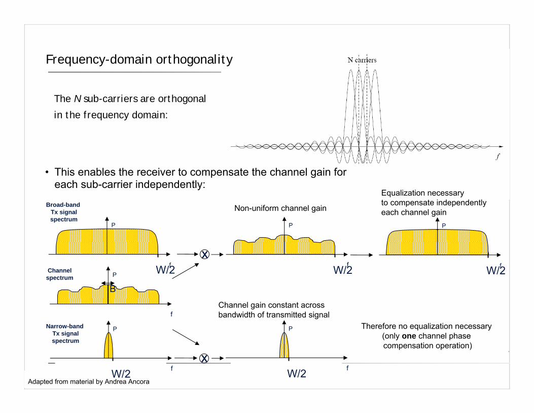
The N sub-carriers are orthogonal
in the frequency domain:
Frequency-domain orthogonality
W/2
P
f
P
fW/2P
f
B
xW/2
P
f
P
fW/2
P
fW/2
Broad-band Tx signalspectrum
Channelspectrum
Narrow-band Tx signalspectrum
Therefore no equalization necessary (only one channel phase compensation operation)
Channel gain constant across bandwidth of transmitted signal
x
Non-uniform channel gain
• This enables the receiver to compensate the channel gain for each sub-carrier independently:
Equalization necessaryto compensate independently each channel gain
Adapted from material by Andrea Ancora
25 | 4G Wireless | Teck Hu
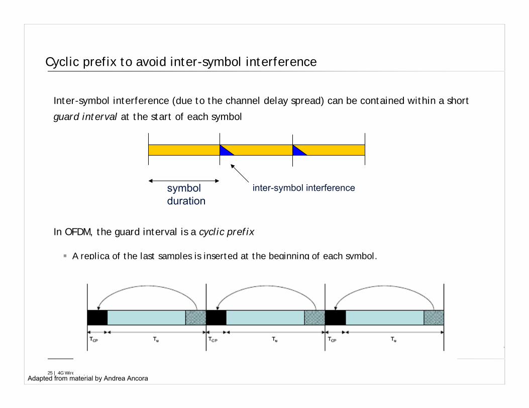
Inter-symbol interference (due to the channel delay spread) can be contained within a short
guard interval at the start of each symbol
In OFDM, the guard interval is a cyclic prefix
A replica of the last samples is inserted at the beginning of each symbol.
Cyclic prefix to avoid inter-symbol interference
symbolduration
inter-symbol interference
Adapted from material by Andrea Ancora
26 | 4G Wireless | Teck Hu
…
Sub-carriersFFT
Time
Symbols
5 MHz Bandwidth
Guard Intervals
…Frequency
1.5MHz Bandwidth
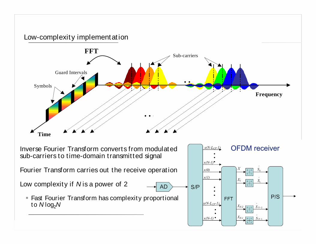
Low-complexity implementation
Inverse Fourier Transform converts from modulated sub-carriers to time-domain transmitted signal
Fourier Transform carries out the receive operation
Low complexity if N is a power of 2
Fast Fourier Transform has complexity proportional to N log2N
OFDM receiver
27 | 4G Wireless | Teck Hu
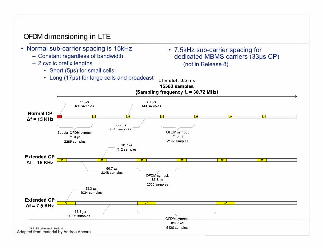
OFDM dimensioning in LTE
• Normal sub-carrier spacing is 15kHz– Constant regardless of bandwidth– 2 cyclic prefix lengths
• Short (5µs) for small cells• Long (17µs) for large cells and broadcast
• 7.5kHz sub-carrier spacing for dedicated MBMS carriers (33µs CP)
(not in Release 8)
Adapted from material by Andrea Ancora
28 | 4G Wireless | Teck Hu
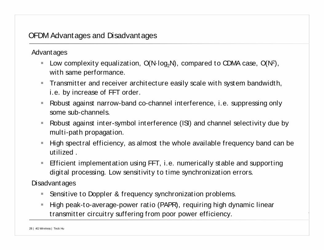
Advantages
Low complexity equalization, O(N·log2N), compared to CDMA case, O(N2), with same performance.
Transmitter and receiver architecture easily scale with system bandwidth, i.e. by increase of FFT order.
Robust against narrow-band co-channel interference, i.e. suppressing only some sub-channels.
Robust against inter-symbol interference (ISI) and channel selectivity due by multi-path propagation.
High spectral efficiency, as almost the whole available frequency band can be utilized .
Efficient implementation using FFT, i.e. numerically stable and supporting digital processing. Low sensitivity to time synchronization errors.
Disadvantages
Sensitive to Doppler & frequency synchronization problems.
High peak-to-average-power ratio (PAPR), requiring high dynamic linear transmitter circuitry suffering from poor power efficiency.
OFDM Advantages and Disadvantages
29 | 4G Wireless | Teck Hu
MIMO Techniques and Modes in LTE
Three types of gain from multiple antennas
Diversity gain
Array/Beamforming gain
Spatial Multiplexing gain
Multiple antenna techniques
Single-user MIMO (SU-MIMO)
Multi-user MIMO (MU-MIMO)
Co-operative multi-point transmission (CoMP)
30 | 4G Wireless | Teck Hu
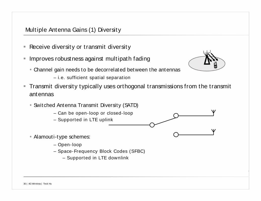
Multiple Antenna Gains (1) Diversity
Receive diversity or transmit diversity
Improves robustness against multipath fading
Channel gain needs to be decorrelated between the antennas– i.e. sufficient spatial separation
Transmit diversity typically uses orthogonal transmissions from the transmit antennas
Switched Antenna Transmit Diversity (SATD)– Can be open-loop or closed-loop– Supported in LTE uplink
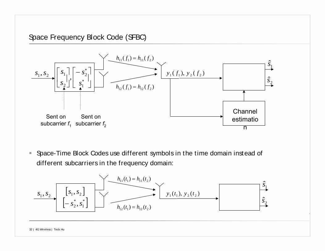
Alamouti-type schemes:– Open-loop– Space-Frequency Block Codes (SFBC)
– Supported in LTE downlink
31 | 4G Wireless | Teck Hu
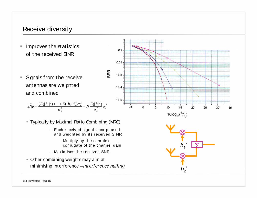
Receive diversity
Improves the statistics of the received SINR
Signals from the receiveantennas are weighted and combined
Typically by Maximal Ratio Combining (MRC)
– Each received signal is co-phased and weighted by its received SINR
– Multiply by the complex conjugate of the channel gain
– Maximises the received SNR
Other combining weights may aim at minimising interference – interference nulling
Σh1*
h2*
22
2
2
2221 )|(|)]|(|...)|(|(
snn
sN hENhEhESNR σσσ
σ=
++=
−
32 | 4G Wireless | Teck Hu
Space Frequency Block Code (SFBC)
Space-Time Block Codes use different symbols in the time domain instead of different subcarriers in the frequency domain:
⎥⎦
⎤⎢⎣
⎡−⎥⎦
⎤⎢⎣
⎡∗
∗
1
2
2
1 ,ss
ss
)()( 211111 fhfh =
)()( 212112 fhfh =
21, ss
Sent on subcarrier f1
Sent on subcarrier f2
Channel estimatio
n
1s)(),( 2211 fyfy
2s
[ ][ ]*
1*2
21
,
,
ss
ss
−
)()( 211111 thth =
)()( 212112 thth =
21, ss1s
)(),( 2211 tyty2s
33 | 4G Wireless | Teck Hu
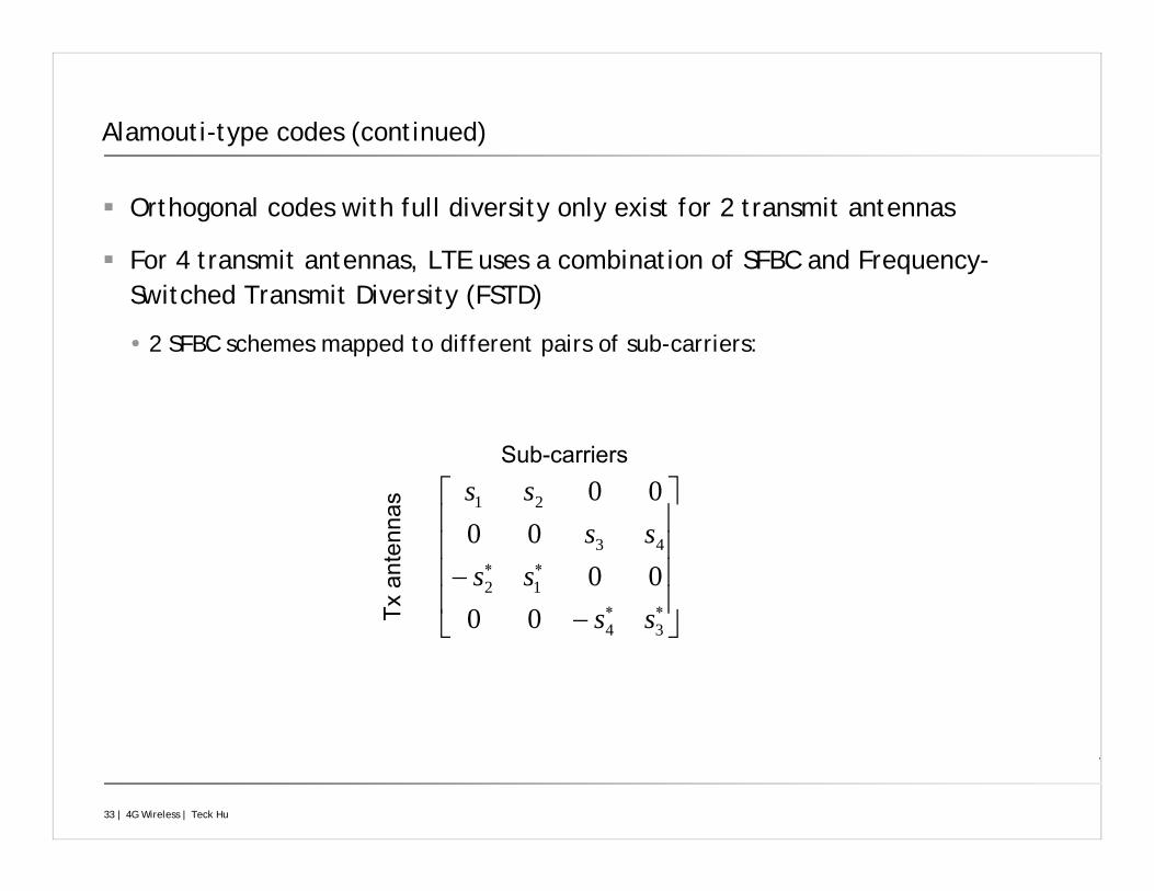
Alamouti-type codes (continued)
Orthogonal codes with full diversity only exist for 2 transmit antennas
For 4 transmit antennas, LTE uses a combination of SFBC and Frequency-Switched Transmit Diversity (FSTD)
2 SFBC schemes mapped to different pairs of sub-carriers:
⎥⎥⎥⎥
⎦
⎤
⎢⎢⎢⎢
⎣
⎡
−−
∗∗
∗∗
34
12
43
21
0000
0000
ssss
ssss
Sub-carriers
Txan
tenn
as
34 | 4G Wireless | Teck Hu
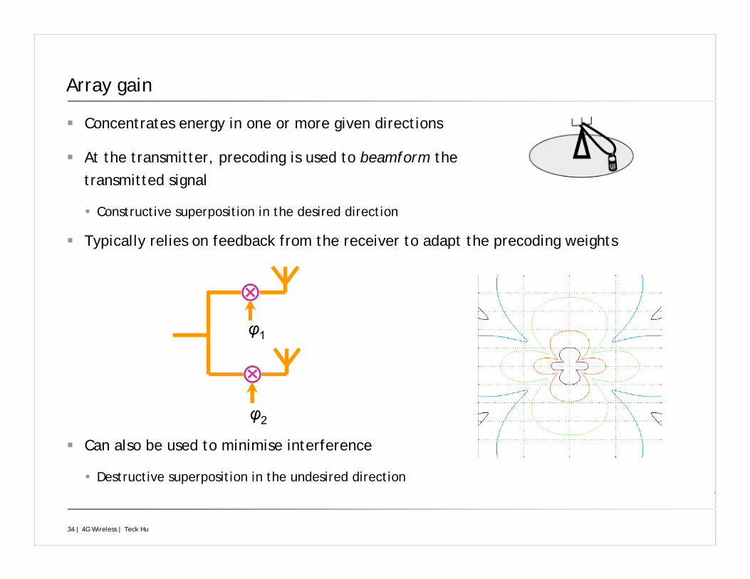
Array gain
Concentrates energy in one or more given directions
At the transmitter, precoding is used to beamform the transmitted signal
Constructive superposition in the desired direction
Typically relies on feedback from the receiver to adapt the precoding weights
Can also be used to minimise interference
Destructive superposition in the undesired direction
φ1
φ2
35 | 4G Wireless | Teck Hu
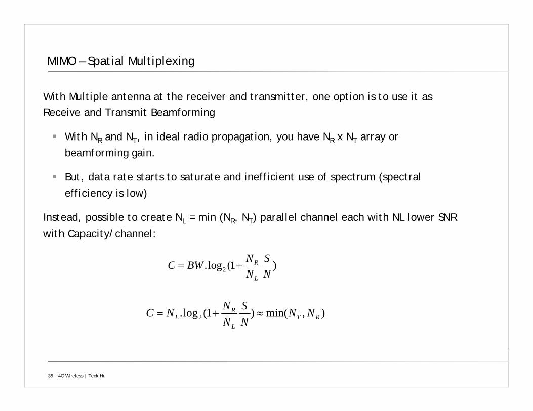
MIMO – Spatial Multiplexing
With Multiple antenna at the receiver and transmitter, one option is to use it as Receive and Transmit Beamforming
With NR and NT, in ideal radio propagation, you have NR x NT array or beamforming gain.
But, data rate starts to saturate and inefficient use of spectrum (spectral efficiency is low)
Instead, possible to create NL = min (NR, NT) parallel channel each with NL lower SNR with Capacity/channel:
)1(log. 2 NS
NNBWC
L
R+=
),min()1(log. 2 RTL
RL NN
NS
NNNC ≈+=
36 | 4G Wireless | Teck Hu
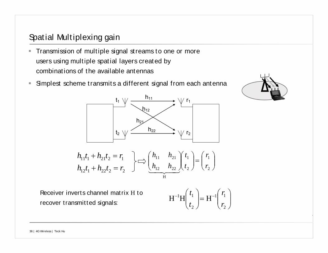
Spatial Multiplexing gain
Transmission of multiple signal streams to one or more users using multiple spatial layers created by combinations of the available antennas
Simplest scheme transmits a different signal from each antenna
t1
t2
r1
r2
h11
h12
h21
h22
2222112
1221111
rththrthth
=+=+
⎟⎟⎠
⎞⎜⎜⎝
⎛=⎟⎟
⎠
⎞⎜⎜⎝
⎛ −−
2
11
2
11 HHHrr
tt Receiver inverts channel matrix H to
recover transmitted signals:
⎟⎟⎠
⎞⎜⎜⎝
⎛=⎟⎟
⎠
⎞⎜⎜⎝
⎛⎟⎟⎠
⎞⎜⎜⎝
⎛
2
1
2
1
H
2212
2111
rr
tt
hhhh
37 | 4G Wireless | Teck Hu
MIMO – Spatial Multiplexing (cont)
A max of NT different signals that can be transmitted with a receiver capable of suppressing a maximum of NR – 1 interference:
Capacity proportional to minimum of number of Transmit and Receive antennas
Considerations:
Low SNR region where it is power limited: already proportional increase in data rate with SNR
Very sensitive to channel matrix invertibility and the closer the channel matrix to singular matrix, the larger the increase in noise e.g. multipath channel with close to identical independent distribution is good but not line of sight channel.
Spatial multiplexing order in realistic channel < NL, a function of the properties of the NR x NT channel matrix
If NL is less then combined baemforming and spatial multiplexing can be used: preCoderbased spatial multiplexing
38 | 4G Wireless | Teck Hu
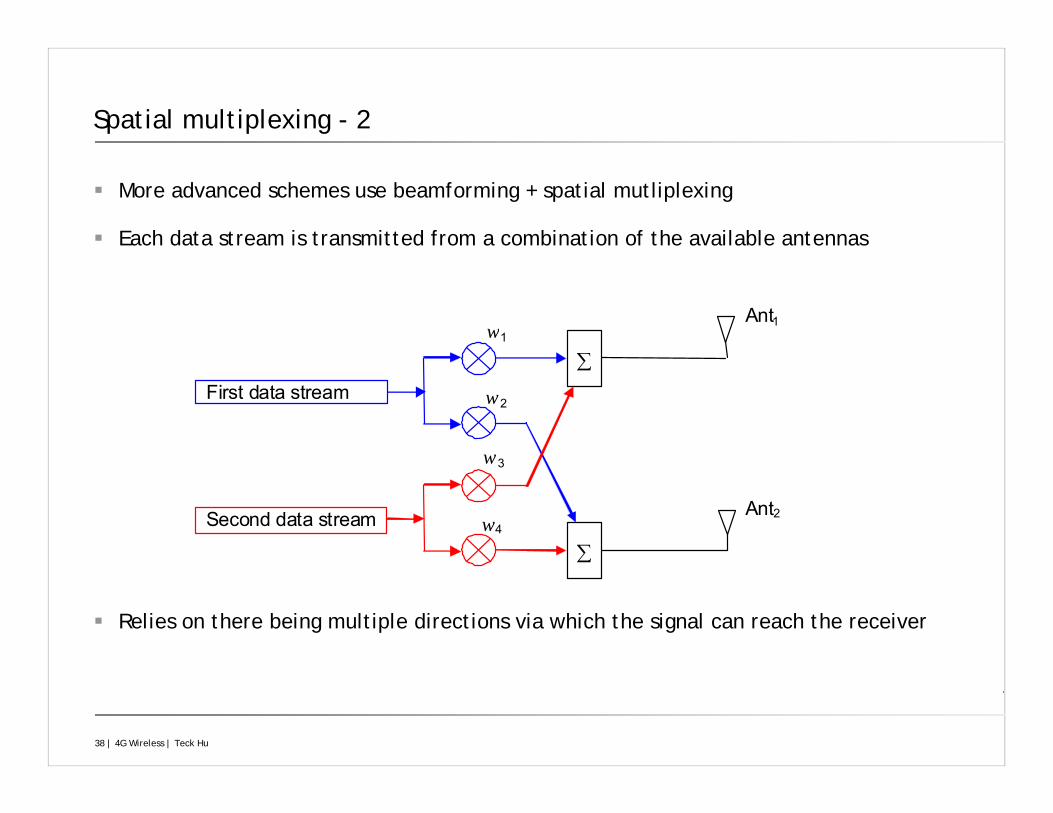
Spatial multiplexing - 2
More advanced schemes use beamforming + spatial mutliplexing
Each data stream is transmitted from a combination of the available antennas
Relies on there being multiple directions via which the signal can reach the receiver
First data stream
Second data stream
Ant1
Ant2
w1
w2
w3
w4
∑
∑
39 | 4G Wireless | Teck Hu
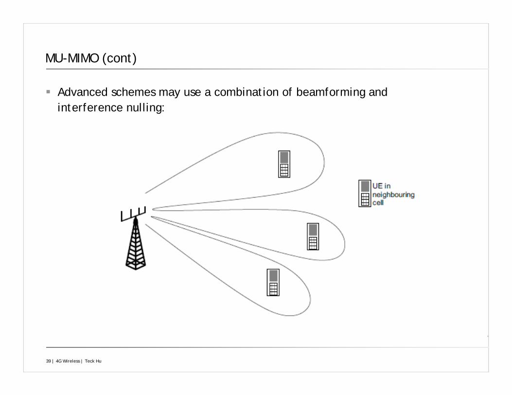
MU-MIMO (cont)
Advanced schemes may use a combination of beamforming and interference nulling:
40 | 4G Wireless | Teck Hu
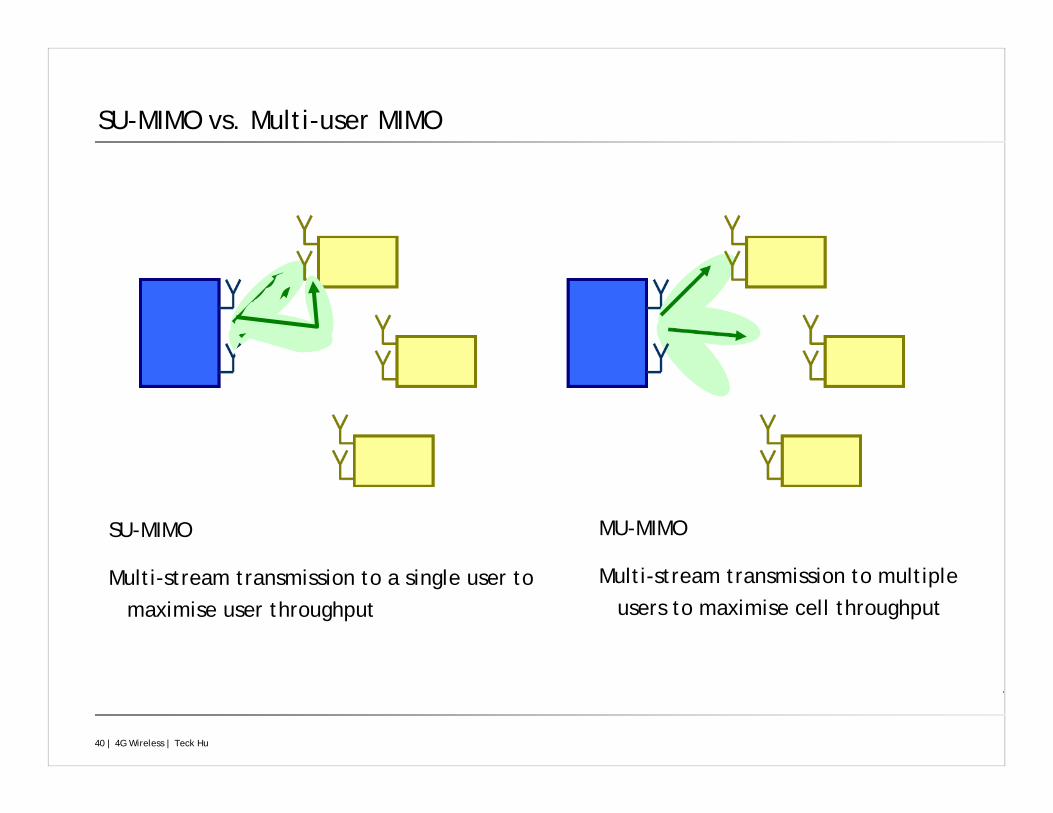
SU-MIMO vs. Multi-user MIMO
SU-MIMO
Multi-stream transmission to a single user to maximise user throughput
MU-MIMO
Multi-stream transmission to multiple users to maximise cell throughput
41 | 4G Wireless | Teck Hu
Feedback Signalling for MIMO
PMI (Precoding Matrix Indicator)
Indicates the UE’s preferred precoding matrix
Selected from a finite “codebook” of precoding matrices
Each precoding matrix corresponds to a set of beams
CQI (Channel Quality Indicator)
Indicates the supportable rate (Modulation and Coding Scheme - MCS) corresponding to the PMI
RI (Rank Indicator)
Indicates the number of spatial layers supported by the channel (rank of the channel matrix)
42 | 4G Wireless | Teck Hu
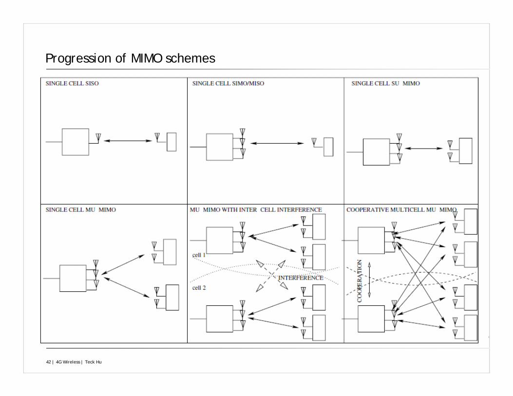
Progression of MIMO schemes
43 | 4G Wireless | Teck Hu
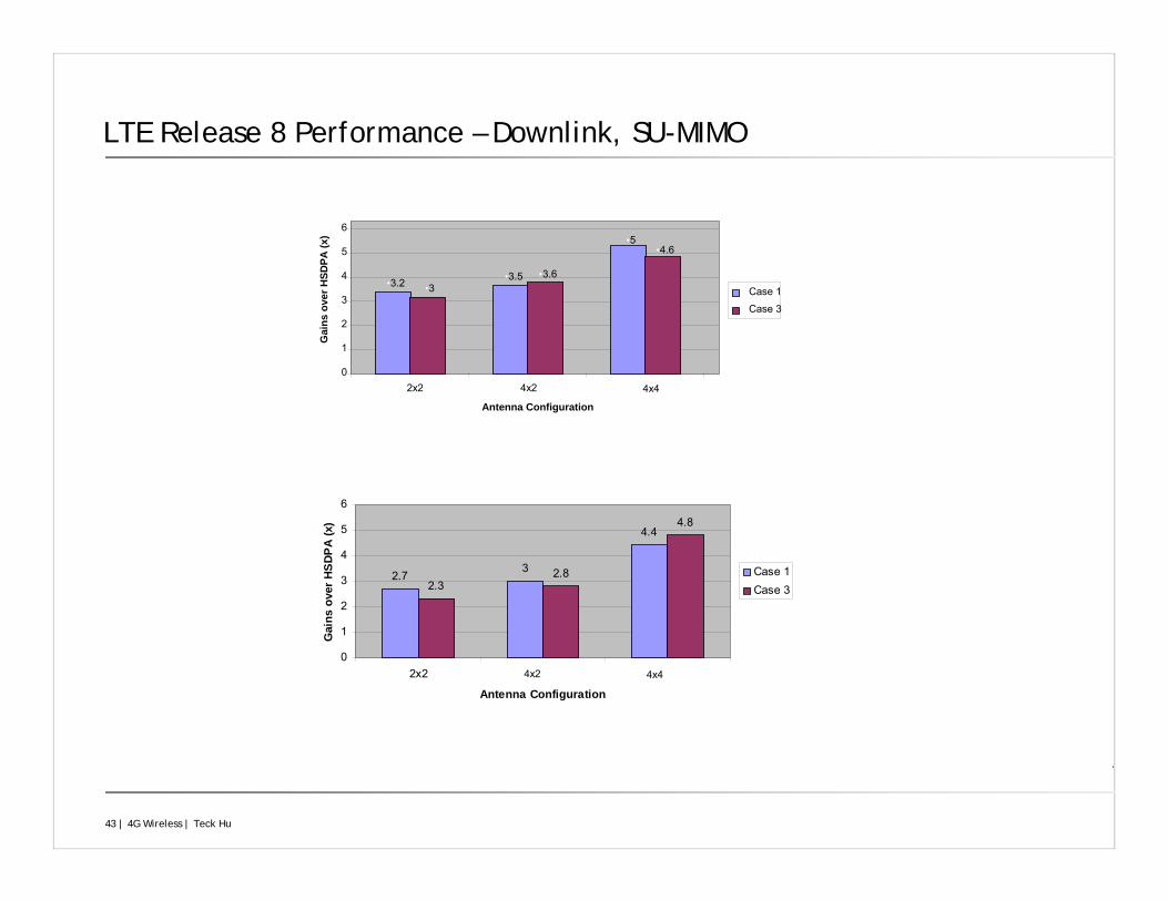
LTE Release 8 Performance – Downlink, SU-MIMO
2.73
4.4
2.32.8
4.8
0
1
2
3
4
5
6
2x2
Antenna Configuration
Gai
ns o
ver H
SDP
A (x
)
Case 1Case 3
•3.2 •3.5
•5
•3•3.6
•4.6
•0
•1
•2
•3
•4
•5
•6
•2x2
•Antenna Configuration
•Gai
ns o
ver H
SDPA
(x)
•Case 1
•Case 3
•4x2
•4x2 •4x4
•4x4
44 | 4G Wireless | Teck Hu
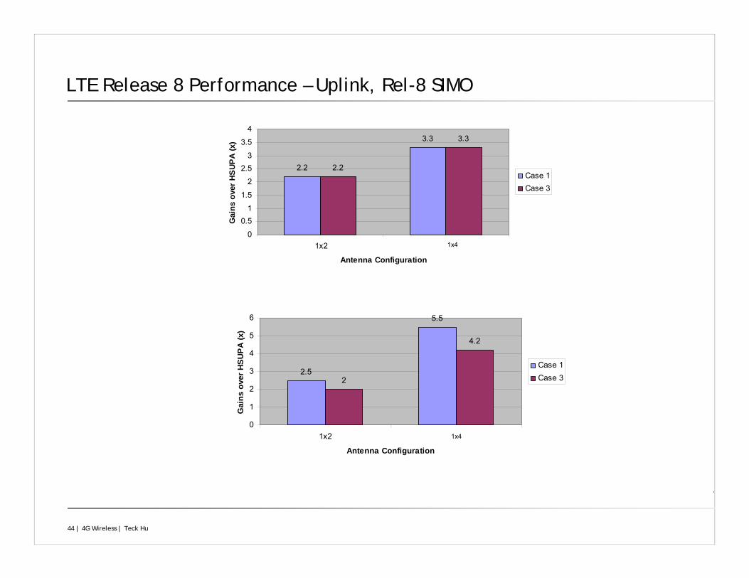
LTE Release 8 Performance – Uplink, Rel-8 SIMO
2.2
3.3
2.2
3.3
0
0.51
1.5
2
2.53
3.5
4
1x2
Antenna Configuration
Gai
ns o
ver H
SUP
A (x
)
Case 1Case 3
2.5
5.5
2
4.2
0
1
2
3
4
5
6
1x2
Antenna Configuration
Gai
ns o
ver H
SUP
A (x
)
Case 1Case 3
•1x4
•1x4
45 | 4G Wireless | Teck Hu
LTE Advanced (LTE-A)
46 | 4G Wireless | Teck Hu
Peak data rate
1 Gbps data rate achieved by 4x4 MIMO and transmission bandwidth wider than approximately 70 MHz
Peak spectrum efficiency
DL: Rel. 8 LTE satisfies IMT-Advanced requirement
UL: Need to double from Release 8 to satisfy IMT-Advanced requirement
LTE-Advanced Motivations and Objectives
47 | 4G Wireless | Teck Hu
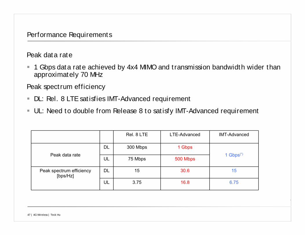
Peak data rate
1 Gbps data rate achieved by 4x4 MIMO and transmission bandwidth wider than approximately 70 MHz
Peak spectrum efficiency
DL: Rel. 8 LTE satisfies IMT-Advanced requirement
UL: Need to double from Release 8 to satisfy IMT-Advanced requirement
Rel. 8 LTE LTE-Advanced IMT-Advanced
Peak data rate
DL 300 Mbps 1 Gbps
1 Gbps(*)
UL 75 Mbps 500 Mbps
Peak spectrum efficiency [bps/Hz]
DL 15 30.6 15
UL 3.75 16.8 6.75
Performance Requirements
48 | 4G Wireless | Teck Hu
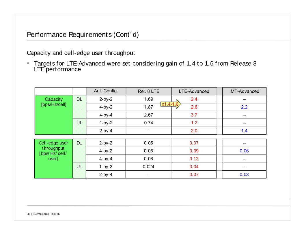
Performance Requirements (Cont’d)
Cell-edge user throughput
[bps/Hz/cell/user]
DL 2-by-2 0.05 0.07 –
4-by-2 0.06 0.09 0.06
4-by-4 0.08 0.12 –
UL 1-by-2 0.024 0.04 –
2-by-4 – 0.07 0.03
Ant. Config. Rel. 8 LTE LTE-Advanced IMT-Advanced
Capacity [bps/Hz/cell]
DL 2-by-2 1.69 2.4 –
4-by-2 1.87 2.6 2.2
4-by-4 2.67 3.7 –
UL 1-by-2 0.74 1.2 –
2-by-4 – 2.0 1.4
x1.4-1.6
Capacity and cell-edge user throughput
Targets for LTE-Advanced were set considering gain of 1.4 to 1.6 from Release 8 LTE performance
49 | 4G Wireless | Teck Hu
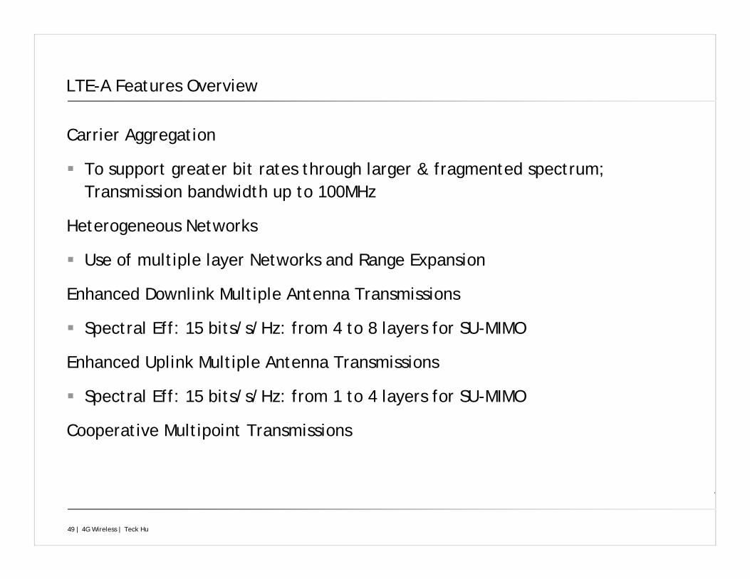
LTE-A Features Overview
Carrier Aggregation
To support greater bit rates through larger & fragmented spectrum; Transmission bandwidth up to 100MHz
Heterogeneous Networks
Use of multiple layer Networks and Range Expansion
Enhanced Downlink Multiple Antenna Transmissions
Spectral Eff: 15 bits/s/Hz: from 4 to 8 layers for SU-MIMO
Enhanced Uplink Multiple Antenna Transmissions
Spectral Eff: 15 bits/s/Hz: from 1 to 4 layers for SU-MIMO
Cooperative Multipoint Transmissions
50 | 4G Wireless | Teck Hu
Carrier Aggregation
Motivations:Satisfy requirements for peak data rate
– Multiple Component Carriers (CCs) up to 100 MHzSpectrum aggregation
– Enables diverse spectrum assignments to be exploited jointly– Both contiguous and non-contiguous aggregation supported
Support heterogeneous network deployment– Cross-carrier scheduling for control channel interference management
Each CC is backward compatible with Rel-8 LTELow complexitySupports legacy terminals
51 | 4G Wireless | Teck Hu
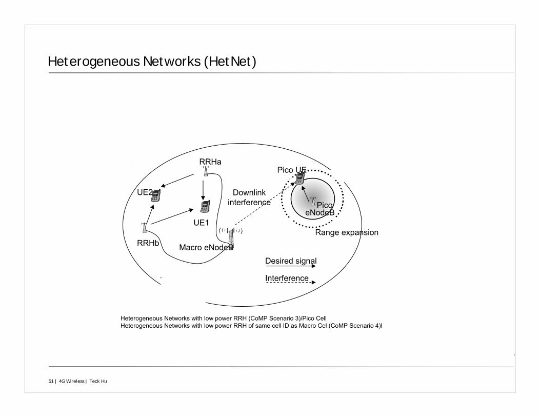
Heterogeneous Networks (HetNet)
Macro eNodeB
Pico eNodeB
Range expansion
Pico UE
UE1
Desired signal
Interference
Downlink interference
UE2
RRHa
RRHb
Heterogeneous Networks with low power RRH (CoMP Scenario 3)/Pico CellHeterogeneous Networks with low power RRH of same cell ID as Macro Cel (CoMP Scenario 4)l
52 | 4G Wireless | Teck Hu
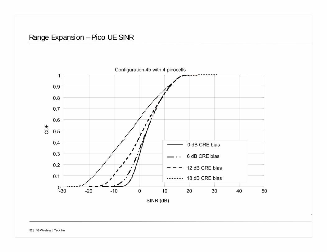
Range Expansion – Pico UE SINR
-30 -20 -10 0 10 20 30 40 500
0.1
0.2
0.3
0.4
0.5
0.6
0.7
0.8
0.9
1
SINR (dB)
CD
F
0 dB CRE bias
6 dB CRE bias
12 dB CRE bias
18 dB CRE bias
Configuration 4b with 4 picocells
53 | 4G Wireless | Teck Hu
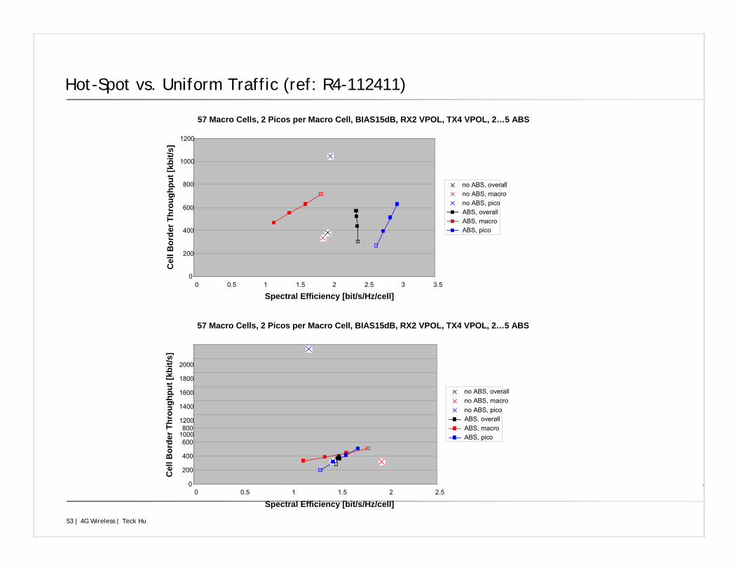
Hot-Spot vs. Uniform Traffic (ref: R4-112411)
•57 Macro Cells, 2 Picos per Macro Cell, BIAS15dB, RX2 VPOL, TX4 VPOL, 2…5 ABS
•0
•200
•400
•600
•800
•1000
•1200
•0 •0.5 •1 •1.5 •2 •2.5 •3 •3.5
•Spectral Efficiency [bit/s/Hz/cell]
•Cel
l Bor
der T
hrou
ghpu
t [kb
it/s]
•no ABS, overall•no ABS, macro•no ABS, pico•ABS, overall•ABS, macro•ABS, pico
•57 Macro Cells, 2 Picos per Macro Cell, BIAS15dB, RX2 VPOL, TX4 VPOL, 2…5 ABS
•0
•200
•400
•600
•800•1000
•1200
•1400
•1600
•1800
•2000
•0 •0.5 •1 •1.5 •2 •2.5
•Spectral Efficiency [bit/s/Hz/cell]
•Cel
l Bor
der T
hrou
ghpu
t [kb
it/s]
•no ABS, overall•no ABS, macro•no ABS, pico•ABS, overall•ABS, macro•ABS, pico
54 | 4G Wireless | Teck Hu
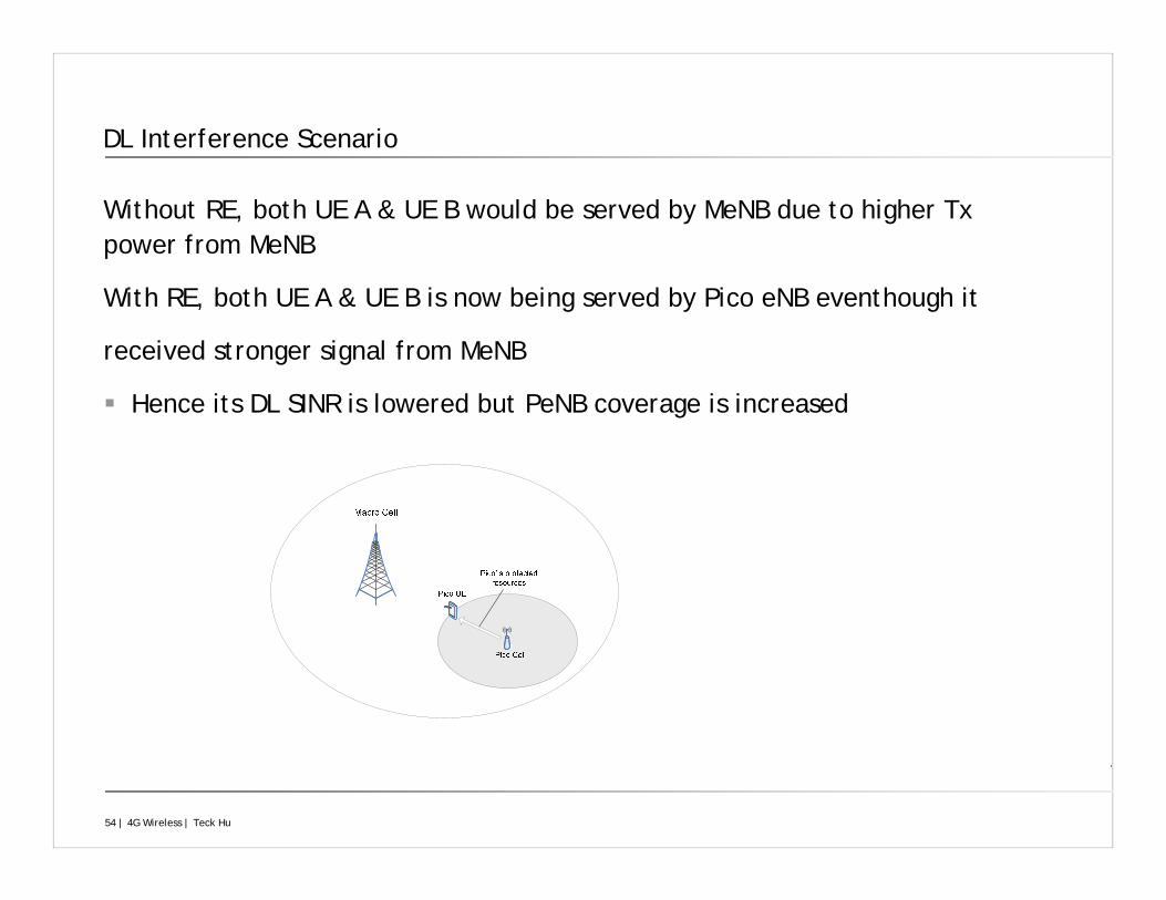
DL Interference Scenario
Without RE, both UE A & UE B would be served by MeNB due to higher Tx power from MeNB
With RE, both UE A & UE B is now being served by Pico eNB eventhough it
received stronger signal from MeNB
Hence its DL SINR is lowered but PeNB coverage is increased
55 | 4G Wireless | Teck Hu
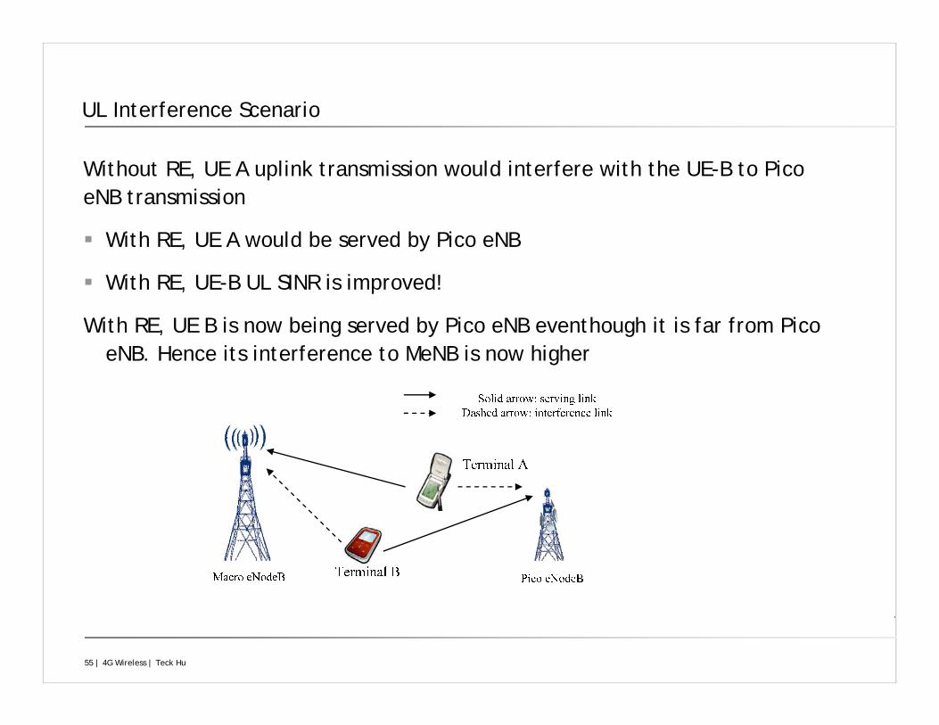
UL Interference Scenario
Without RE, UE A uplink transmission would interfere with the UE-B to Pico eNB transmission
With RE, UE A would be served by Pico eNB
With RE, UE-B UL SINR is improved!
With RE, UE B is now being served by Pico eNB eventhough it is far from Pico eNB. Hence its interference to MeNB is now higher
56 | 4G Wireless | Teck Hu
Relay
Objective: Supports deployment of cells in areas where wired backhaul is not available or very expensive – Coverage Extension
In Homogeneous deployments, it may have the following challenges:
Severe propagation loss due to higher frequency bands
Poor cell edge coverage
Potential coverage hole
In a Macro-Relay deployments:
Decode and forward scheme
Break a low quality link into multiple better links
Enhance the throughput of cell edge users
Extend cell range & Longer battery life
57 | 4G Wireless | Teck Hu
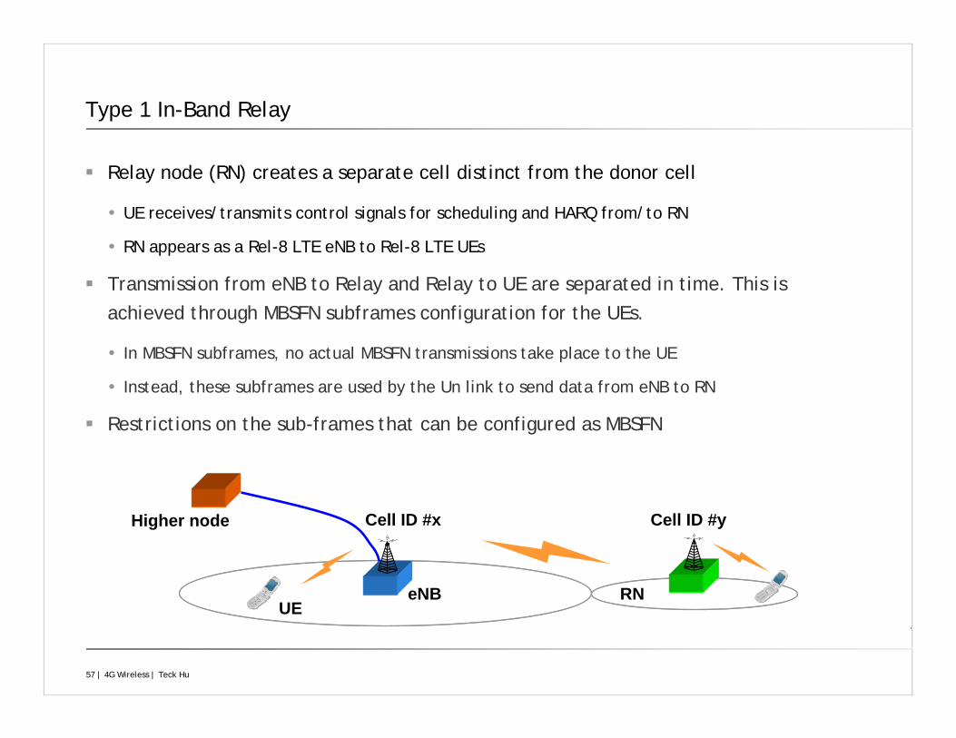
eNB RNUE
Cell ID #x Cell ID #yHigher node
Type 1 In-Band Relay
Relay node (RN) creates a separate cell distinct from the donor cell
UE receives/transmits control signals for scheduling and HARQ from/to RN
RN appears as a Rel-8 LTE eNB to Rel-8 LTE UEs
Transmission from eNB to Relay and Relay to UE are separated in time. This is achieved through MBSFN subframes configuration for the UEs.
In MBSFN subframes, no actual MBSFN transmissions take place to the UE
Instead, these subframes are used by the Un link to send data from eNB to RN
Restrictions on the sub-frames that can be configured as MBSFN
58 | 4G Wireless | Teck Hu
Beyond LTE-Advanced
Mobile Data rates expected to double annually & ARPU is to be flat & Spectrum will be capped at some point. So..
Spectral Efficiency and Cost Efficiency
Advanced Signal Processing
Offloading
Denser Heterogeneous Networks
Options?
Higher bits/s/Hz: Network MIMO, CoMP…
Offloading: to WiFi, Device to Device, Cognitive Radio..
59 | 4G Wireless | Teck Hu
Coordinated MultiPoint (CoMP) Transmission and Reception
Also known as Cooperative MIMO
Goal is improve User experience, especially Cell-Edge Users
Downlink CoMP
Information exchange protocols between eNBs
Feedback (CSI) enhancements: Multicell Channel State Feedback from the UE
Uplink CoMP
Mostly realizable in current Network implementation
Receiver Processing and Backhaul Coordination
60 | 4G Wireless | Teck Hu
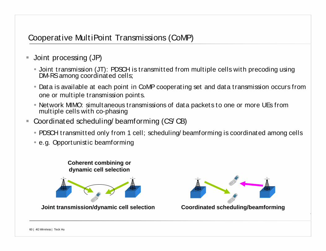
Cooperative MultiPoint Transmissions (CoMP)
Joint processing (JP)
Joint transmission (JT): PDSCH is transmitted from multiple cells with precoding using DM-RS among coordinated cells;
Data is available at each point in CoMP cooperating set and data transmission occurs from one or multiple transmission points.
Network MIMO: simultaneous transmissions of data packets to one or more UEs from multiple cells with co-phasing
Coordinated scheduling/beamforming (CS/CB)
PDSCH transmitted only from 1 cell; scheduling/beamforming is coordinated among cellse.g. Opportunistic beamforming
Coherent combining or dynamic cell selection
Coordinated scheduling/beamformingJoint transmission/dynamic cell selection
61 | 4G Wireless | Teck Hu
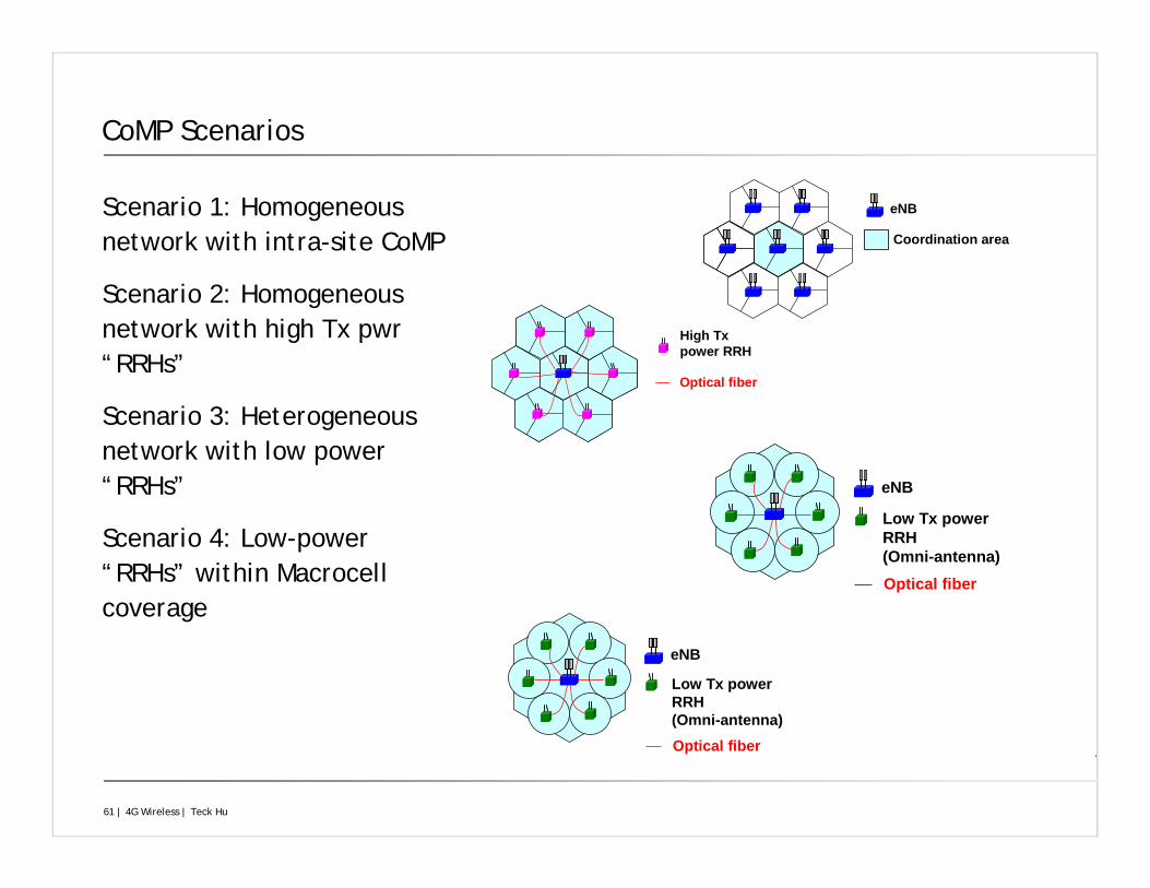
CoMP Scenarios
Scenario 1: Homogeneous network with intra-site CoMP
Scenario 2: Homogeneous network with high Tx pwr“RRHs”
Scenario 3: Heterogeneous network with low power “RRHs”
Scenario 4: Low-power “RRHs” within Macrocellcoverage
Low Tx power RRH(Omni-antenna)
eNB
Optical fiber
Low Tx power RRH(Omni-antenna)
eNB
Optical fiber
High Txpower RRH
Optical fiber
eNB
Coordination area
62 | 4G Wireless | Teck Hu
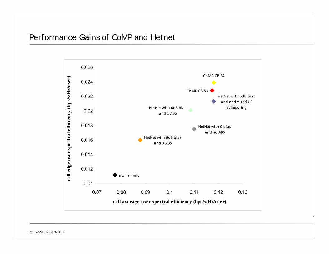
Performance Gains of CoMP and Hetnet
CoMP CB S4
CoMP CB S3HetNet with 6dB bias and optimized UE
scheduling
HetNet with 6dB bias and 3 ABS
HetNet with 6dB bias and 1 ABS
HetNet with 0 bias and no ABS
macro only
0.01
0.012
0.014
0.016
0.018
0.02
0.022
0.024
0.026
0.07 0.08 0.09 0.1 0.11 0.12 0.13
cell average user spectral efficiency (bps/s/Hz/user)
cell
edge
use
r sp
ectr
al e
ffici
ency
(bps
/s/H
z/us
er)
63 | 4G Wireless | Teck Hu
References & Further Reading
www.3GPP.org
S. Sesia, I. Taufik and M. Baker, LTE - The UMTS Long Term Evolution: From Theory to Practice, Wiley 2011.
E. Dahlman, Stefan Parkvall, Johan Skold, 4G: LTE/LTE-Advanced for Mobile Broadband.
T. Hu, J. Pang, H-J. Su, “LTE-Advanced Heterogeneous Networks: Release 10 and Beyond,” ICC workshop, June 2012.