Embed Size (px)
Citation preview

APOLLO NEWS REFERENCE
LUNAR MODULE
QUICK REFERENCE DATA
DIMENSIONS
LM:
22 ft. 11 in. (legs extended) Height
Diameter 31 ft. (diagonally across extended landing gear)
Ascent stage:
Height
Diameter
Descent stage:
Height
Diameter
GENERAL
Vehicle weight:
Earth launch (with crew and propellant)
LM (dry)
Ascent stage (dry)
Descent stage (dry)
Propellant weight:
Ascent stage Descent stage
RCS
Pressurized volume
Habitable volume
Cabin temperature
Cabin pressure
Batteries:
Height
Width
Length
Weight (each, filled)
Electrical requirements: Inputs
From Electrical Power Subsystem (Commander's
and LM Pilot:s buses)
From Ascent engine latching device of control
electronics section
From Explosive Devices batteries (systems A
and B)
From descent engine control assembly
Outputs
To initiators (in cartridge assemblies)
Explosive Devices relay boxes
IIRUMMAN
,
12 ft.4 in.
14ft. 1 in.
10 ft. 7 in.
13 ft. 10 in.
36,100 lb. (approx.)
10, 800 lb. (approx.)
4,700 lb. (approx.)
6,100 lb. (approx.)
5,200 lb. (approx.) 19,500 lb. (approx.)
600 lb. (approx.)
235 cu. ft.
160 cu. ft.
75° F
4.8 ±. 0.2 psia
3.03 inches
2.75 inches
6.78 inches
135 pounds
2 8 volts de
2 8 volts de
37.1 volts de (open-circuit voltage)
35.0 volts de (minimum)
2 8 volts de
3.5 amperes for 10 milliseconds (minimum)
7.5 to 15.0 amperes de (for at least 10
milliseconds)
LV-1
APOLLO NEWS REFERENCE
The NASA/Grumman Apollo Lunar Module (LM) after descending to the lunar surface from lunar orbit, provides a base from which the astronauts explore the landing site and enables the astronauts to take off from the lunar surface to rendezvous and dock with the orbiting Command and Service Modules (CSM). The LM consists of an ascent stage and a descent stage. Both stages function as a single unit during separation from the CM, lunar descent, and lunar stay. The descent stage serves as a launching platform from which the ascent stage lifts off from the lunar surface. The ascent stage operates independently during the lunar ascent, rendezvous, and docking phase of the Apollo mission.
The ascent and descent stages are joined by four interstage fittings that are explosively severed at staging. Subsystem lines and umbilicals required for subsystem continuity between the stages are either explosively severed or automatically disconnected when the stages are separated.
R-2A LM Configuration
ASCENT STAGE
The ascent stage, control center of the LM, is comprised of three main areas: crew compartment, midsection, and equipment bay.
The crew compartment and midsection make up the cabin, which has an overall volume of 235 cubic feet. The basic structure is primarily aluminum alloy; titanium is used for fittings and fasteners. Aircraft-type construction methods are used. Skin and web panels are chemically milled to reduce weight. Mechanical fasteners join the major structural assemblies with epoxy as a sealant. Structural members are fusion welded wherever possible, to minimize cabin air pressurization leaks. The basic structure includes supports for throst control engine clusters and various antennas. The entire basic structure is enveloped by thermal insulation and a micrometeoroid shield.
R-3
/ THERMAL AND
MICROMETEOROID SHIELD
MIDSECTION
CREW COMPARTMENT
Ascent Stage Structure
AFT EQUIPMENT BAY
TCA ClUSTER SUPPORT
LV-2 GRUMMAN
,
APOLLO NEWS REFERENCE
The ascent stage is designed to:
Provide a controlled environment for the two astronauts while separated from the CSM.
Provide required visibility for lunar landing, stay, and ascent; and for rendezvous and docking with the CM.
Provide for astronaut and equipment transfer between the LM and CM and between the LM and the lunar surface.
Protect the astronauts and the equipment from micrometeoroid penetration.
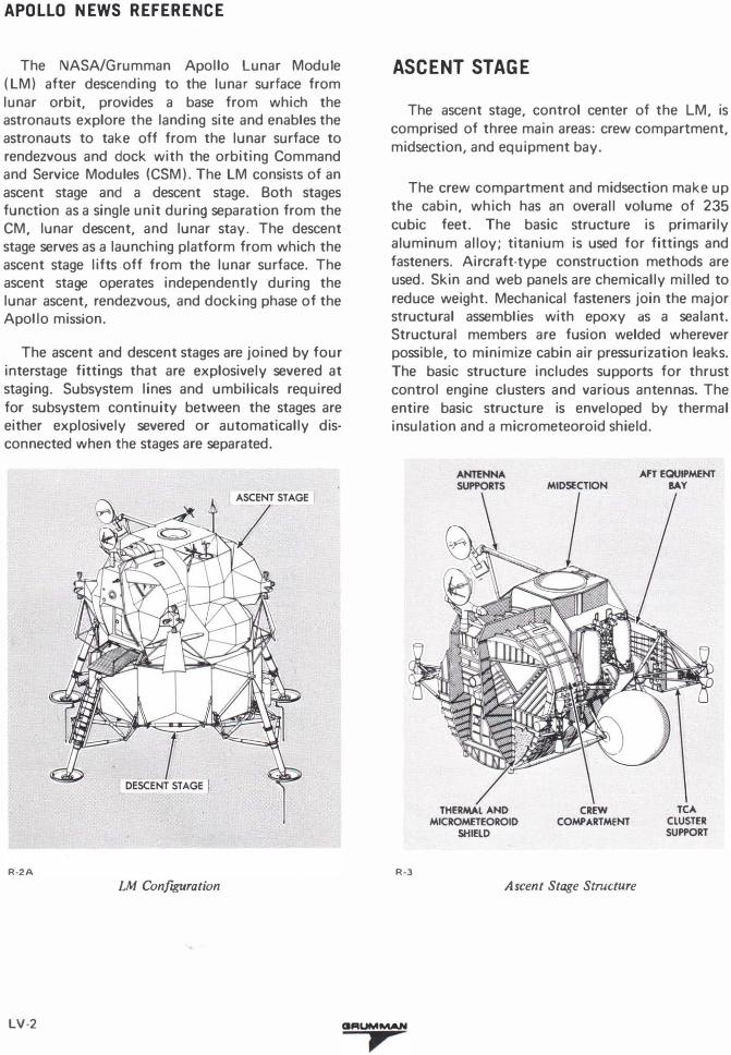
CREW COMPARTMENT
The crew compartment is the frontal area of the ascent stage; it is cylindrical (92 inches in diameter and 42 inches deep). The Commander's flight
R·4A
CREWMAN RESTRAINT
(BOTH SIDES)
PANEL 5 PANEL 4
ALIGNMENT
station is at the left; the LM Pilot's at the right. The flight-station centerlines are 44 inches apart. For maximum downward vision the upper part of the compartment is constructed to extend forward of the lower portion. The area has control and display panels, body restraints, lanc;ling aids, a front window for each astronaut, a docking window above the Commander's station and other accessory equipment. Each flight station has an attitude controller, a thrust/translation controller, and adjustable armrests. There is a hatch in the front face assembly of the compartment.
A portable life support system (PLSS) donning station is behind the optical alignment station. Attachment points for an S-band in-flight antenna are provided on the front face assembly and for a rendezvous radar antenna on the upper structural beams of the crew compartment.
MAIN PANEL/CABIN FLOODLIGHT (BOTH SIDES)
7-----x<-PANEL 2 CAMERA
GLARESHIELD (BOTH SIDES)
HELMET STOWAGE PANEL6 STOWAGE (POSITION NO. 1) (BOTH SIDES)
(BOTH SIDES)
Crew Compartment Interior
ORUMMAN
, LV-3
APOLLO NEWS REFERENCE
The crew compartment deck (flight station floor) measures approximately 36 by 55 inches. Nonflammable Velcro pile is bonded to the decks' top surface; a hooked Velcro on the soles of the astronauts' boots provides a restraining force to hold the astronaut to the deck during zero-g flight. Handgrips, aligned with the forward hatch and recessed in the deck, aid ingress and egress.
The control and display panels contain all devices necessary to control, monitor, and observe subsystems performance. The arrangement of the panels permits either astronaut to fly the LM to the CSM. All panels are canted to facilitate viewing. Six of the panels are in front of the flight stations. The upper two panels - one inboard of each flight station - are at eye level. These panels are shock mounted to dampen vibrations. The next two lower panels are centered between the flight stations to enable sharing of the control functions. One of the remaining two front panels is in front of each flight station, at waist height. The Commander's panel contains lighting, mission timer, engine, and thrust chamber controls. The LM Pilot's panel has abort guidance subsystem controls. To the left of the Commander's station are three panels: a five-tier circuit breaker panel at the top, an explosive devices and communications audio control panel, and an earth and lunar orbital rate display panel. To the right of the LM Pilot's station are three panels: the uppermost is a fourtier circuit breaker panel, the center panel contains controls and displays for electrical power, and the bottom panel contains communications controls and displays. The circuit breaker panels are canted to the line of sight so that the white band on each circuit breaker can be seen when the breakers are open.
FORWARD HATCH
The forward hatch is in the front face assembly, just below the lower display panels. The hatch is used for transfer of astronauts and equipment between the LM and lunar surface, or for in-flight extravehicular activity (EVA) while docked with the CM. The hatch is approximately 32 inches
square; it is hinged to swing inboard when opened. A cam latch assembly holds the hatch in the closed position; the assembly forces a lip, around the outer circumference of the hatch, into a preloaded elastomeric silicone compound seal secured to the LM structure. Cabin pressurization forces the hatch lip further into the seal, ensuring a pressure-tight contact. A handle is provided on both sides of the hatch, for latch operation. To open the hatch, the cabin must be completely depressurized by opening a cabin relief and dump valve on the hatch. When the cabin is completely depressurized, the hatch can be opened by rotating the latch handle. The cabin relief and dump valve can also be operated from outside the LM. Quick-release pins in the latch plate and hinges may be pulled from inside the LM to open the hatch in an emergency.
WINDOWS
The two triangular windows in the front face assembly each have approximately 2 square feet of viewing area; they are canted down to the side to permit adequate peripheral and downward visibility. The docking window above the Commander's flight station has approximately 80 square inches of viewing area and provides visibility for docking maneuvers. All three windows consist of two separated panes, vented to space. The outer pane is of low-strength, annealed material that inhibits micrometeoroid penetration. The outer surface of this pane is coated with 59 layers of blue-red thermal control, metallic oxide, to reduce infrared and ultraviolet light transmission. The inner surface of the outer pane has a highefficiency, antireflective coating. This coating is also a metallic oxide, which reduces the mirror effect of the windows and increases their normal light-transmission efficiency. The inner pane of each window is of chemically tempered, highstrength structural glass. The inner pane of the front windows has a seal (the docking window has two seals) between it and the window frame and is bolted to the frame through a metal retainer. The inner pane has the high-efficiency antireflective coating on its inner surface and a defogging coating on its outer surface.
LV-4 GRUMMAN
,
APOLLO NEWS REFERENCE
All three windows are electrically heated to prevent fogging. The temperature of the windows is not monitored. Heater operation directly affects crew visibility; proper operation is, therefore, visually determined by the astronauts.
A window shade, with an antireflective coating on its outboard side, is provided for each window. Normally, the shade is rolled up at the window edge. A glareshield mounted between each front window and the control and flight display panels reduces window reflection of internal panel lighting.
EQUIPMENT STOWAGE
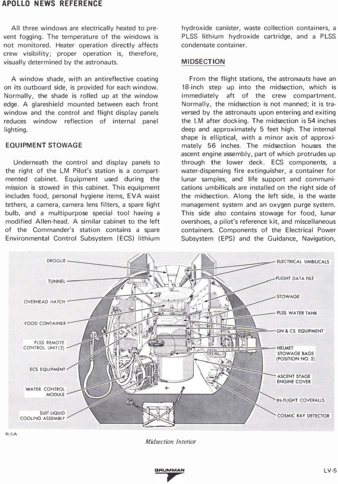
Underneath the control and display panels to the right of the LM Pilot's station is a compartmented cabinet. Equipment used during the mission is stowed in this cabinet. This equipment includes food, personal hygiene items, EVA waist tethers, a camera, camera lens filters, a spare light bulb, and a multipurpose special tool having a modified Allen-head. A similar cabinet to the left of the Commander's station contains a spare Environmental Control Subsystem (ECS) lithium
R-SA
DROGUE
OVERHEAD HATCH
FOOD CONTAINER
PLSS REMOTE CONTROL UNIT(2)
ECS EQUIPMENT
WATER CONTROL MODULE
SUIT LIQUID COOLING ASSEMBLY
hydroxide canister, waste collection containers, a PLSS lithium hydroxide cartridge, and a PLSS condensate container.
MIDSECTION
From the flight stations, the astronauts have an 18-inch step up into the midsection, which is immediately aft of the crew compartment. Normally, the midsection is not manned; it is traversed by the astronauts upon entering and exiting the LM after docking. The midsection is 54 inches deep and approximately 5 feet high. The internal shape is elliptical, with a minor axis of approximately 56 inches. The midsection houses the ascent engine assembly, part of which protrudes up through the lower deck. ECS components, a water-dispensing fire extinguisher, a container for lunar samples, and life support and communications umbilicals are installed on the right side of the midsection. Along the left side, is the waste management system and an oxygen purge system. This side also contains stowage for food, lunar overshoes, a pilot's reference kit, and miscellaneous containers. Components of the Electrical Power Subsystem (EPS) and the Guidance, Navigation,
DATA FILE
IN-FLIGHT COVERALLS
Midsection Interior
GRUMMAN
, LV-5
APOLLO NEWS REFERENCE
and Control Subsystem (GN&CS) are mounted on the aft bulkhead. A cylindrical cover protects the accessories section from the protruding part of the engine. The top of the cover is used as a rest position for one of the astronauts and as a platform for initially observing the lunar surface through the overhead (docking) hatch. Above the hatch is a docking tunnel; directly forward of the hatch, PLSS fittings are mounted. These fittings aid the astronauts in donning their PLSS units.
Construction of the midsection is similar to that of the crew compartment, but the midsection has a bulkhead at each end. The aft bulkhead supports the aft equipment bay structure. In addition to the lower deck to which the ascent engine is mounted, there are two others. One of these supports the overhead hatch and the lower end of the docking tunnel; the other, supports the upper end of the docking tunnel and absorbs some of the stresses imposed during docking. All decks are made of integrally stiffened machined aluminum alloy, or reinforced chemically milled web. The exterior structure forms a cradle around the midsection to absorb or transmit all stress loads applied to the ascent stage. Stress loads applied to beams on top of the crew compartment are transmitted through midsection beams, to the aft bulkhead and, in turn, to the interstage fittings. The external structure, along the sides of the midsection, supports propellant subsystem storage tanks and S-band steerable and VHF in-flight antennas. The aft midsection bulkhead supports propellant and ECS tanks, an aft equipment rack assembly and the Reaction Control System (RCS) two aft thrust clusters. A docking target, used for aligning the LM with the CSM during docking, is mounted on the upper left structure of the midsection exterior.
OVERHEAD HATCH
The overhead hatch, approximately 33 inches in diameter, is at the top centerline of the midsection. When the LM and CM are docked, the hatch permits transfer of astronauts and equipment. The astronauts pass through the hatch, head first. Handgrips in the docking tunnel immediately above the hatch aid in crew and equipment transfer. The hatch has an off-center latch that can be operated from either side of the hatch. The hatch
is opened inward by rotating the latch handle 90°. A preloaded elastomeric silicone compound seal is mounted in the hatch frame structure. When the latch is closed, a lip near the outer circumference of the hatch enters the seal, ensuring a pressure tight contact. Normal cabin pressurization forces the hatch into its seal. To open the hatch, the cabin must be depressurized by opening a cabin relief and dump valve, which is within the hatch structure. The valve can be operated with a handle on each side of the hatch.
DOCKING TUNNEL
The docking tunnel, immediately above the overhead hatch, provides a structural interface between the LM and the CM to permit transfer of equipment and astronauts without exposure to space environment. The tunnel is 32 inches in diameter and 16 inches long. A ring at the top of the tunnel is compatible with a docking ring on the CM. The CM docking ring has automatic clamping latches. The ring is concentric with the nominal centerline of thrust of the ascent and descent engines. The drogue, a portion of the docking mechanism, is secured below the ring to three mounts in the LM tunnel so that it can mate with the docking probe of the CM. When the CM and LM are docked, the rings are joined; this ensures structural continuity for transmitting midcourse correction and lunar orbit injection stresses throughout vehicle basic structure.
AFT EQUIPMENT BAY
The aft equipment bay is an unpressurized area formed by the aft midsection bulkhead and the equipment rack, which is cantilevered approximately 33 inches aft of the bulkhead. The equipment rack assembly has integral cold rails that transfer heat from electronic and electrical equipment (components of the GN&CS, EPS, and Communications Subsystems) mounted on the rack. The cold rails are mounted vertically in the rack structural frame. Water-glycol flows through the cold rails.
Two gaseous oxygen tanks and two gaseous helium tanks are secured to the truss members between the midsection aft bulkhead and the
LV·6 IIRUMMAN
,
APOLLO NEWS REFERENCE
equipment rack. ECS and Main Propulsion Subsystem components that do not require a pressurized environment or acesss by the astronauts are mounted to the outboard side of the aft bulkhead. The equipment rack and the aft bulkhead support the aft RCS thrust clusters.
THERMAL AND MICROMETEOROID SHIELD
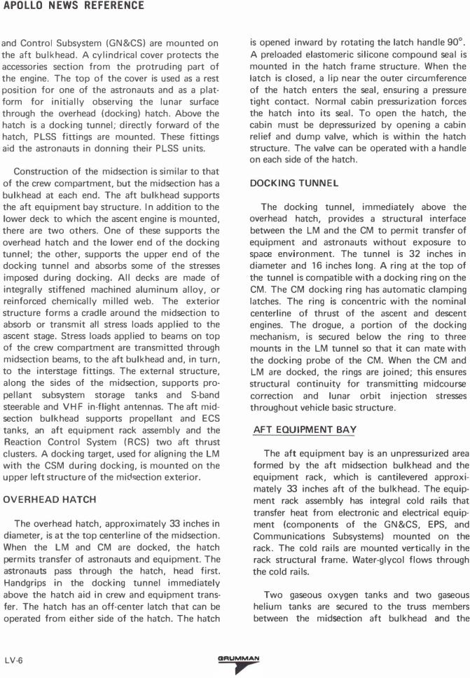
After the LM is removed from the spacecraftLunar Module adapter (SLA), it is exposed to micrometeoroids and solar radiation. To protect the LM astronauts and equipment from temperature extremes, active and passive thermal control is used. Active thermal control is provided by the ECS. Passive thermal control isolates the vehicle interior structure and equipment from its external environment to sustain acceptable temperature limits throughout the lunar mission. The entire ascent stage structure is enclosed within a thermal blanket and a micrometeoroid shield. Glass fiber
INCONEL INCONEL MESH
.:...._=...:...�...;_--"----'-..:..;_:........:.-"-- NICKEL FOIL
§--=-----------i�j��S�!��� ALUMINIZED j§ POL YIMIDE (H-FILM)
����������ALUMINIZE D � POLYIMIOE (MYLAR)
R-6
Typical Thermal Blanket and Micrometeoroid Shield
standoffs, of low thermal conductivity, hold the blanket away from the structural skin. Aluminum frames around the propellant tanks prevent contact between tanks and blanket. The thermal blanket consists of multiple-layered (at least 25 layers) of aluminized sheet (mylar or H-film). Each layer is only 0.00015 inch thick and is coated on one side with a microinch thickness of aluminum. To make an even more effective insulation, the polymide
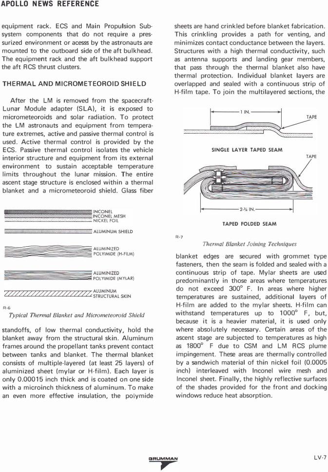
sheets are hand crinkled before blanket fabrication. This crinkling provides a path for venting, and minimizes contact conductance between the layers. Structures with a high thermal conductivity, such as antenna supports and landing gear members, that pass through the thermal blanket also have thermal protection. Individual blanket layers are overlapped and sealed with a continuous strip of H-film tape. To join the multilayered sections, the
SINGLE LAYER TAPED SEAM
TAPED FOLDED SEAM
R-7
Thermal Blanket Joining Techniques
blanket edges are secured with grommet type fasteners, then the seam is folded and sealed with a continuous strip of tape. Mylar sheets are used predominantly in those areas where temperatures do not exceed 300° F. In areas where higher temperatures are sustained, additional layers of H-film are added to the mylar sheets. H-film can withstand temperatures up to 1000° F, but, because it is a heavier material, it is used only where absolutely necessary. Certain areas of the ascent stage are subjected to temperatures as high as 1800° F due to CSM and LM RCS plume impingement. These areas are thermally controlled by a sandwich material of thin nickel foil (0.0005 inch) interleaved with lnconel wire mesh and lnconel sheet. Finally, the highly reflective surfaces of the shades provided for the front and docking windows reduce heat absorption.
IIRUMMAN LV-7
,
APOLLO NEWS REFERENCE
-.-------2'-IN.SPACE MI��.-------�·
. .........---. �
. �---
·�r:::�-INBOARD It
R-8
Typical Micrometeoroid Protection
END CLOSURE QUADRANT 1 BULKHEAD
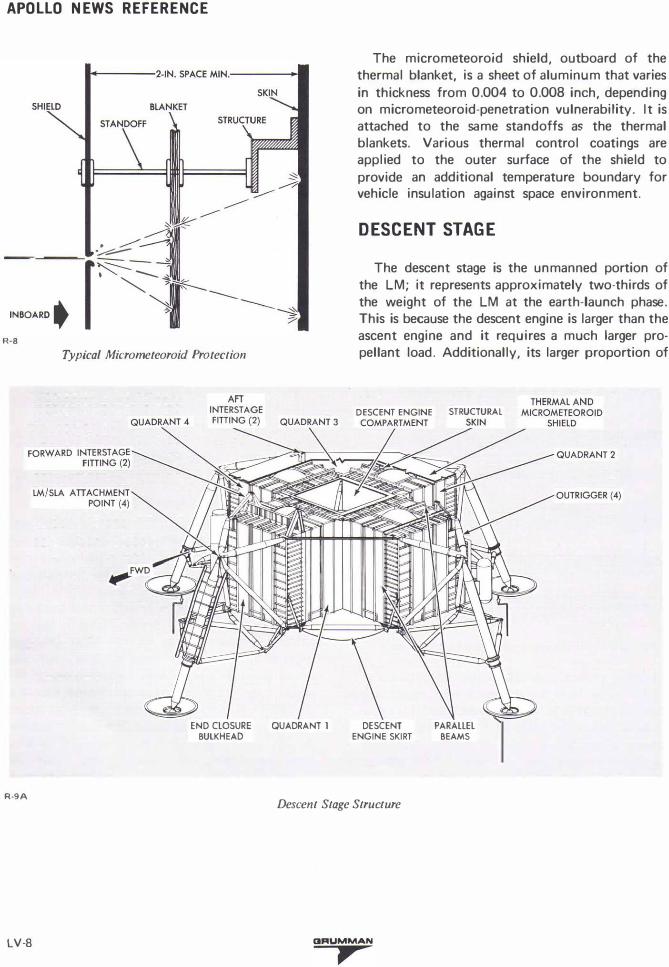
The micrometeoroid shield, outboard of the thermal blanket, is a sheet of aluminum that varies in thickness from 0.004 to 0.008 inch, depending on micrometeoroid-penetration vulnerability. It is attached to the same standoffs as the thermal blankets. Various thermal control coatings are applied to the outer surface of the shield to provide an additional temperature boundary for vehicle insulation against space environment.
DESCENT STAGE
The descent stage is the unmanned portion of the LM; it represents approximately two-thirds of the weight of the LM at the earth-launch phase. This is because the descent engine is larger than the ascent engine and it requires a much larger propellant load. Additionally, its larger proportion of
DESCENT ENGINE STRUCTURAL
DESCENT ENGINE SKIRT
PARALLEL BEAMS
R-9A Descent Stage Structure
LV-8 IJRUMMAN
,
APOLLO NEWS REFERENCE
weight results from necessity of the descent stage to:
(1) Support the entire ascent stage. (2) Provide for attachment of the landing gear. (3) Support the complete LM in the SLA. (4) Provide structure to support the scientific
and communications equipment to be used on the lunar surface.
(5) Act as the launching platform of the ascent stage.
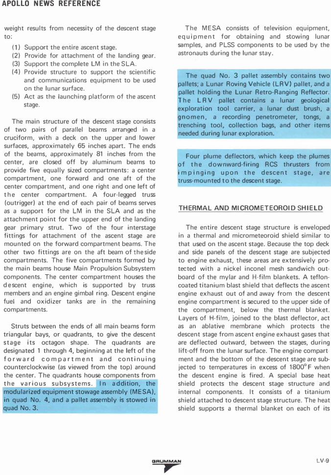
The main structure of the descent stage consists of two pairs of parallel beams arranged in a cruciform, with a deck on the upper and lower surfaces, approximately 65 inches apart. The ends of the beams, approximately 81 inches from the center, are closed off by aluminum beams to provide five equally sized compartments: a center compartment, one forward and one aft of the center compartment, and one right and one left of t h e center compartment. A four-legged truss (outrigger) at the end of each pair of beams serves as a support for the LM in the SLA and as the attachment point for the upper end of the landing gear primary strut. Two of the four interstage fittings for attachment of the ascent stage are mounted on the forward compartment beams. The other two fittings are on the aft beam of the side compartments. The five compartments formed by the main beams house Main Propulsion Subsystem components. The center compartment houses the d e scent engine, which is supported by truss members and an engine gimbal ring. Descent engine fuel and oxidizer tanks are in the remaining compartments.
Struts between the ends of all main beams form triangular bays, or quadrants, to give the descent stage its octagon shape. The quadrants are designated 1 through 4, beginning at the left of the f o r w a r d c o m p a r t m e nt and c o nt inuing counterclockwise (as viewed from the top) around the center. The quadrants house components from the v a r i o u s subsystems. I n a ddition, the modularized equipment stowage assembly (MESA), in quad No. 4, and a pallet assembly is stowed in quad No. 3.
The MESA consists of television equipment, equipment for obtaining and stowing lunar samples, and PLSS components to be used by the astronauts during the lunar stay.
The quad No. 3 pallet assembly contains two pallets; a Lunar Roving Vehicle (LRV) pallet, and a pallet holding the Lunar Retro-Ranging Reflector. 1 h e L RV pallet contains a lunar geological exploration tool carrier, a lunar dust brush, a gnomen, a recording penetrometer, tongs, a trenching tool, collection bags, and other items needed during lunar exploration.
Four plume deflectors, which keep the plumes o f t h e downward-firing RCS thrusters from i m p i n ging u p o n t h e descent stage, are truss-mounted to the descent stage.
THERMAL AND MICROMETEOROID SHIELD
The entire descent stage structure is enveloped in a thermal and micrometeoroid shield similar to that used on the ascent stage. Because the top deck and side panels of the descent stage are subjected to engine exhaust, these areas are extensively protected with a nickel inconel mesh sandwich outboard of the mylar and H-film blankets. A tefloncoated titanium blast shield that deflects the ascent engine exhaust out of and away from the descent engine compartment is secured to the upper side of the compartment, below the thermal blanket. Layers of H-film, joined to the blast deflector, act as an ablative membrane which protects the descent stage from ascent engine exhaust gases that are deflected outward, between the stages, during lift-off from the lunar surface. The engine compart ment and the bottom of the descent stage are subjected to temperatures in excess of 1800° F when the descent engine is fired. A special base heat shield protects the descent stage structure and internal components. It consists of a titanium shield attached to descent stage structure. The heat shield supports a thermal blanket on each of its
GRUMMAN LV·9
,
APOLLO NEWS REFERENCE
sides. The thermal blanket that faces the engine nozzle consists of multiple layers of nickel foil and glass wool and an outer layer of H-film. This blanket acts as a protective membrane to withstand engine exhaust gas back pressures at lunar touchdown and prevent heat, absorbed by the lunar surface during LM landing, from radiating back into the descent stage. Twenty-five layers of H-film make up the blanket on the other side of the titanium. A flange-like ring of columbium backed with a fibrous (Min-K) insulation is attached directly to the engine nozzle extension and joined to the base heat shield by an annular bellows of 25-layer H-film. This bellows arrangement permits descent engine gimbaling, but prevents engine heat from leaking into the engine compartment.
LANDING GEAR
The landing gear provides the impact attenuation required to land the LM on the lunar surface, prevents tipover of the LM on a lunar surface with a 6° general slope having 24-inch depressions or protuberances, and supports the LM during lunar stay and lunar launch. Landing impact is attenuated to load levels that preserves the LM structural integrity. At earth launch, the landing gear is retracted to reduce the overall size. It remains retracted until the docked CSM and LM attain lunar orbit and the astronauts have transferred to the LM. Before the LM is separated from the CSM, the Commander in the LM operates the landing gear deployment switch to extend the gear. At this time landing gear uplocks are explosively released, allowing springs in deployment mechanisms to extend the gear. Once extended, the landing gear is locked in place by downlock mechanisms.
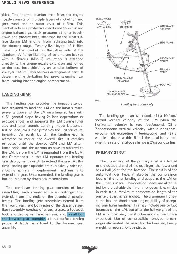
The cantilever landing gear consists of four assemblies, each connected to an outrigger that extends from the ends of the structural parallel beams. The landing gear assemblies extend from the front, rear, and both sides of the descent stage. Each assembly consists of struts, trusses, a footpad,
lock and deployment mechanisms, and, on all but the forward gear assembly, a lunar surface sensing probe. A ladder is affixed to the forward gear assembly.
DEPLOYMENT
AND
DOWN LOCK MECHANISM
R-11
DESCENT
STAGE
STRUCTUR
·
E
.
·. /OUTRIGGER
I ASSEMBLY
t:l.
�4 j{ ,"( �SIDE FRAME
� �
Landing Gear Assembly
The landing gear can withstand: ( 1) a 1 0-foot/ second vertical velocity of the LM when the horizontal velocity is zero feet/second, (2) a 7-foot/second vertical velocity with a horizontal velocity not exceeding 4 feet/second, and (3) a vehicle attitude within 6° of the local horizontal when the rate of attitude change is 2°/second or less.
PRIMARY STRUT
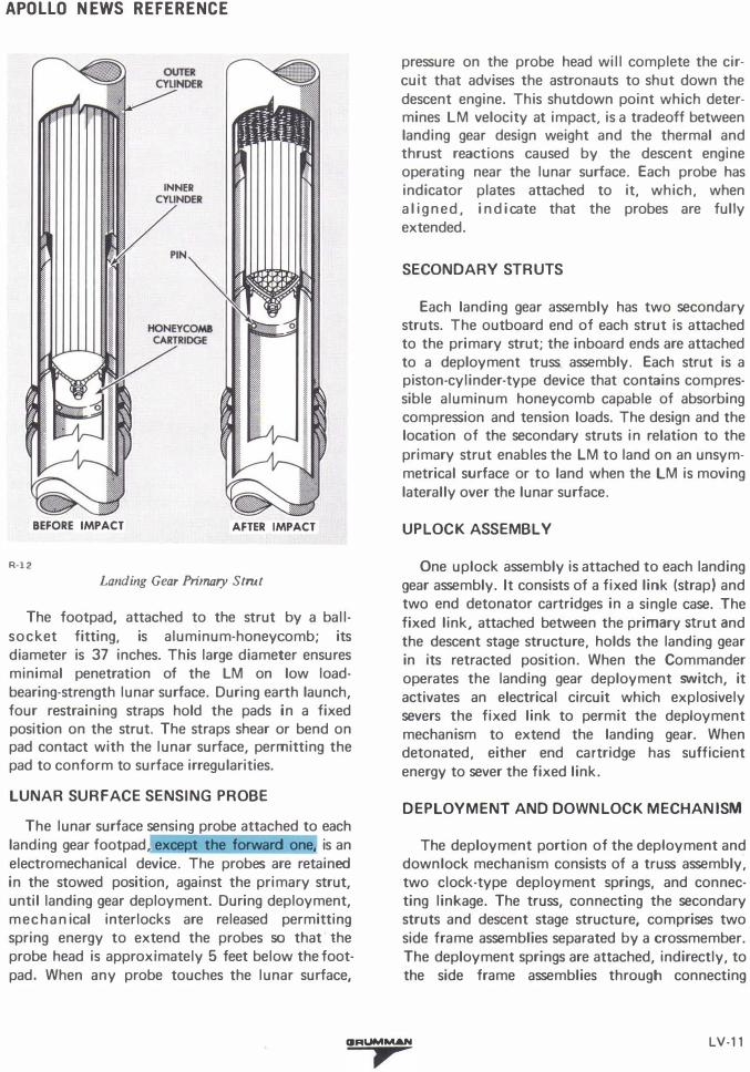
The upper end of the primary strut is attached to the outboard end of the outrigger; the lower end has a ball joint for the footpad. The strut is of the piston-cylinder type; it absorbs the compression load of the lunar landing and supports the LM on the lunar surface. Compression loads are attenuated by a crushable aluminum-honeycomb cartridge in each strut. Maximum compression length of the primary strut is 32 inches. The aluminum honeycomb has the shock-absorbing capability of accepting one lunar landing. This may include one or two bounces of the LM, but after the full weight of the LM is on the gear, the shock-absorbing medium is expended. Use of compressible honeycomb cartridges eliminated the need for thick-walled, heavyweight, pneudraulic-type struts.
LV·10 IJRUMMAN
,
APOLLO NEWS REFERENCE
R-12
INNER CYliNDER
v . IN "
BEFORE IMPACT AFTER IMPACT
Landing Gear Primary Strut
The footpad, attached to the strut by a ballsocket fitting, is aluminum-honeycomb; its diameter is 37 inches. This large diameter ensures minimal penetration of the LM on low loadbearing-strength lunar surface. During earth launch, four restraining straps hold the pads in a fixed position on the strut. The straps shear or bend on pad contact with the lunar surface, permitting the pad to conform to surface irregularities.
LUNAR SURFACE SENSING PROBE
The lunar surface sensing probe attached to each landing gear footpad, except the forward one, is an electromechanical device. The probes are retained in the stowed position, against the primary strut, until landing gear deployment. During deployment, mechanical interlocks are released permitting spring energy to extend the probes so that the probe head is approximately 5 feet below the footpad. When any probe touches the lunar surface,
pressure on the probe head will complete the circuit that advises the astronauts to shut down the descent engine. This shutdown point which determines LM velocity at impact, is a tradeoff between landing gear design weight and the thermal and thrust reactions caused by the descent engine operating near the lunar surface. Each probe has indicator plates attached to it, which, when al igned, indicate that the probes are fully extended.
SECONDARY STRUTS
Each landing gear assembly has two secondary struts. The outboard end of each strut is attached to the primary strut; the inboard ends are attached to a deployment truss assembly. Each strut is a piston-cylinder-type device that contains compressible aluminum honeycomb capable of absorbing compression and tension loads. The design and the location of the secondary struts in relation to the primary strut enables the LM to land on an unsymmetrical surface or to land when the LM is moving laterally over the lunar surface.
UPLOCK ASSEMBLY
One uplock assembly is attached to each landing gear assembly. It consists of a fixed link (strap) and two end detonator cartridges in a single case. The fixed link, attached between the primary strut and the descent stage structure, holds the landing gear in its retracted position. When the Commander operates the landing gear deployment switch, it activates an electrical circuit which explosively severs the fixed link to permit the deployment mechanism to extend the landing gear. When detonated, either end cartridge has sufficient energy to sever the fixed link.
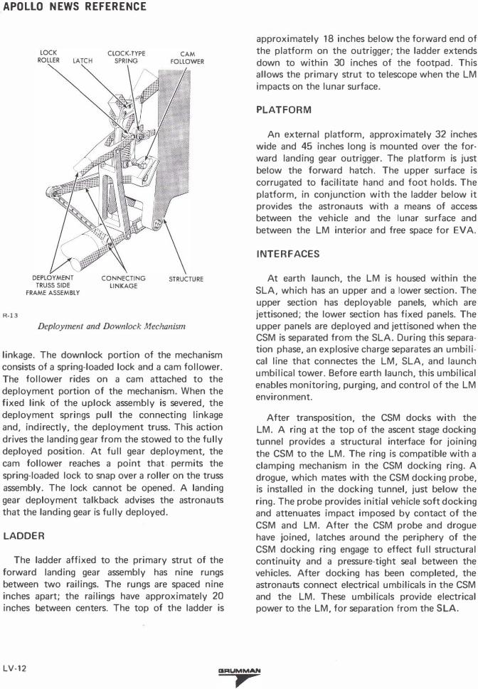
DEPLOYMENT AND DOWNLOCK MECHANISM
The deployment portion of the deployment and downlock mechanism consists of a truss assembly, two clock-type deployment springs, and connecting linkage. The truss, connecting the secondary struts and descent stage structure, comprises two side frame assemblies separated by a crossmember. The deployment springs are attached, indirectly, to the side frame assemblies through connecting
CIRUMMAN LV-11
,
APOLLO NEWS REFERENCE
R-13
CLOCK-TYPE
LATCH SPRING
DEPLOYMENT
TRUSS SIDE
FRAME ASSEMBLY
CONNECTING
LINKAGE
CAM
FOLLOWER
STRUCTURE
Deployment and Downlock Mechanism
linkage. The downlock portion of the mechanism consists of a spring-loaded lock and a cam follower. The follower rides on a cam attached to the deployment portion of the mechanism. When the fixed link of the uplock assembly is severed, the deployment springs pull the connecting linkage and, indirectly, the deployment truss. This action drives the landing gear from the stowed to the fully deployed position. At full gear deployment, the cam follower reaches a point that permits the spring-loaded lock to snap over a roller on the truss assembly. The lock cannot be opened. A landing gear deployment talkback advises the astronauts that the landing gear is fully deployed.
LADDER
The ladder affixed to the primary strut of the forward landing gear assembly has nine rungs between two railings. The rungs are spaced nine inches apart; the railings have approximately 20 inches between centers. The top of the ladder is
approximately 18 inches below the forward end of the platform on the outrigger; the ladder extends down to within 30 inches of the footpad. This allows the primary strut to telescope when the LM impacts on the lunar surface.
PLATFORM
An external platform, approximately 32 inches wide and 45 inches long is mounted over the forward landing gear outrigger. The platform is just below the forward hatch. The upper surface is corrugated to facilitate hand and foot holds. The platform, in conjunction with the ladder below it provides the astronauts with a means of access between the vehicle and the lunar surface and between the LM interior and free space for EVA.
INTERFACES
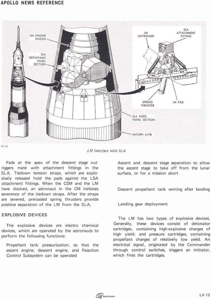
At earth launch, the LM is housed within the SLA, which has an upper and a lower section. The upper section has deployable panels, which are jettisoned; the lower section has fixed panels. The upper panels are deployed and jettisoned when the CSM is separated from the SLA. During this separation phase, an explosive charge separates an umbilical line that connectes the LM, SLA, and launch umbilical tower. Before earth launch, this umbilical enables monitoring, purging, and control of the LM environment.
After transposition, the CSM docks with the LM. A ring at the top of the ascent stage docking tunnel provides a structural interface for joining the CSM to the LM. The ring is compatible with a clamping mechanism in the CSM docking ring. A drogue, which mates with the CSM docking probe, is installed in the docking tunnel, just below the ring. The probe provides initial vehicle soft docking and attenuates impact imposed by contact of the CSM and LM. After the CSM probe and drogue have joined, latches around the periphery of the CSM docking ring engage to effect full structural continuity and a pressure-tight seal between the vehicles. After docking has been completed, the astronauts connect electrical umbilicals in the CSM and the LM. These umbilicals provide electrical power to the LM, for separation from the SLA.
LV-12 CIRUMMAN
,
APOLLO NEWS REFERENCE
R-14 LM Interface with SLA
Pads at the apex of the descent stage outriggers mate with attachment fittings in the SLA. Tiedown tension straps, which are explosively released hold the pads against the LSA attachment fittings. When the CSM and the LM have docked, an astronaut in the CM initiates severence of the tiedown straps. After the straps are severed, preloaded spring thrusters provide positive separation of the LM from the S LA.
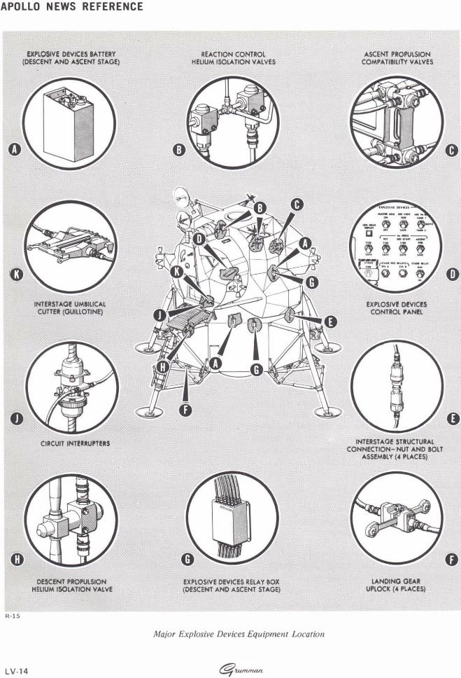
EXPLOSIVE DEVICES
The explosive devices are electro chemical devices, which are operated by the astronauts to perform the following functions:
Propellant tank pressurization, so that the ascent engine, descent engine, and Reaction Control Subsystem can be operated
Ascent and descent stage separation to allow the ascent stage to take off from the lunar surface, or for a mission abort
Descent propellant tank venting after landing
Landing gear deployment
The LM has two types of explosive devices. Generally, these devices consist of detonator cartridges, containing high-explosive charges of high yield; and pressure cartridges, containing propellant charges of relatively low yield. An electrical signal, originated by the Commander through control switches, triggers an initiator, which fires the cartridges.
-'Wmnuvz. LV-13
APOLLO NEWS REFERENCE
EXPLOSIVE DEVICES lA TTERY (DESCENT AND ASCENT STAGE)
'0
R-15
LV-14
INTERST AOI! UMIILICAL CUTTER (GUILLOTINE)
CIRCUIT INTI!IIIIU"I!RS
DESCENT PROPULSION HELIUM ISOLATION VALVE
REACTION CONTROl HELIUM ISOLATION VAl YES
EXPLOSIVE DEVICES RELAY BOX (DESCENT AND ASCENT STAGE)
Major Explosive Devices Equipment Location
ASCENT PROPULSION COMPATIIILITY VALVES
EXPLOSIVI! DI!VICI!S CONTROL PANI!L
INTERSTAOI! STRUCTURAL CONNECTION-NUT AND tOLT
ASSI!MILY (4 I"LACES)
LANDINO GEAR UPLOCK (4 PLACES)
0
APOLLO NEWS REFERENCE
ABORTSEQUENCING
CONTROL TIME �----------------C •
O•
MMA--•
N•DE• �·S--------------•
LM--
P•IL
•O
•T�
----------------------� DELAy CIRCUIT BREAKER CIRCUIT BREAKER
r..:!,"\ -·
0 0 --------------- ---------------l----------------
IX,lOSIY( OlVI((S
AELD (SYSTEM A) DE!.,.";, NT
.....,.. .. ,. 06 voNT .uc ... ,.. ASCENT He PRESS STAGE SIGNAL "" "" nu , ... , (SYSTEM A)
� ..,, LOG GUt � 8 �""'" 09l0<
ll OOf .... ,_,
r;;-- :s ':r£!�1 '-SC£Nf fill "" flU ...
AflD (SYSTEM 8) STAGE SIGNAL � � � � ASCENT He PRESS (SYSTEM I)
[} . .
EXPlOSIVE DEVICES
8ATIERY A {IN ASCENT STAGE)
EXPlOSIVE DEVICES RELAYS BOX A
Ufl SoUl SAfl u.n
EXPLOSIVE DEVICI5 RELAYS BOX 8
EXPLOSIVE DEVICES SUBSYSTEM
EXPlOSIVE DEVICES
8ATIERY 8 (IN DESCENT STAGE)
'-------------
R-16
._ ________ . EXPLOSIVE DEVICES ·-------...
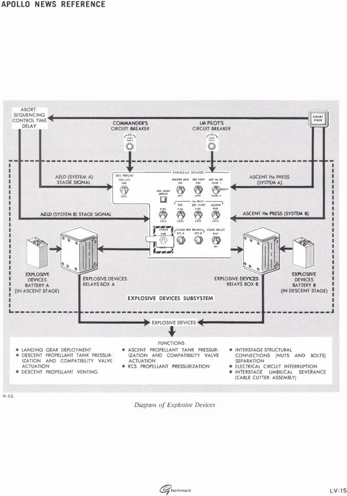
• LANDING GEAR DEPLOYMENT • DESCENT PROPELLANT TANK PRESSUR
IZATION AND COMPATIBILITY VALVE ACTUATION
• DESCENT PROPELLANT VENTING
+ FUNCTIONS
• ASCENT PROPELLANT TANK PRESSURIZATION AND COMPATIBILITY VALVE ACTUATION
• RCS PROPELLANT PRESSURIZATION
Diagram of l:.xplosive Devices
c§f U.unnlfl/L
• INTERSTAGE STRUCTURAL CONNECTIONS (NUTS AND BOLTS) SEPARATION
• ELECTRICAL CIRCUIT INTERRUPTION e INTERST AGE UMBILICAL SEVERANCE
(CABLE CUTIER ASSEMBLY)
LV-15
APOLLO NEWS REFERENCE
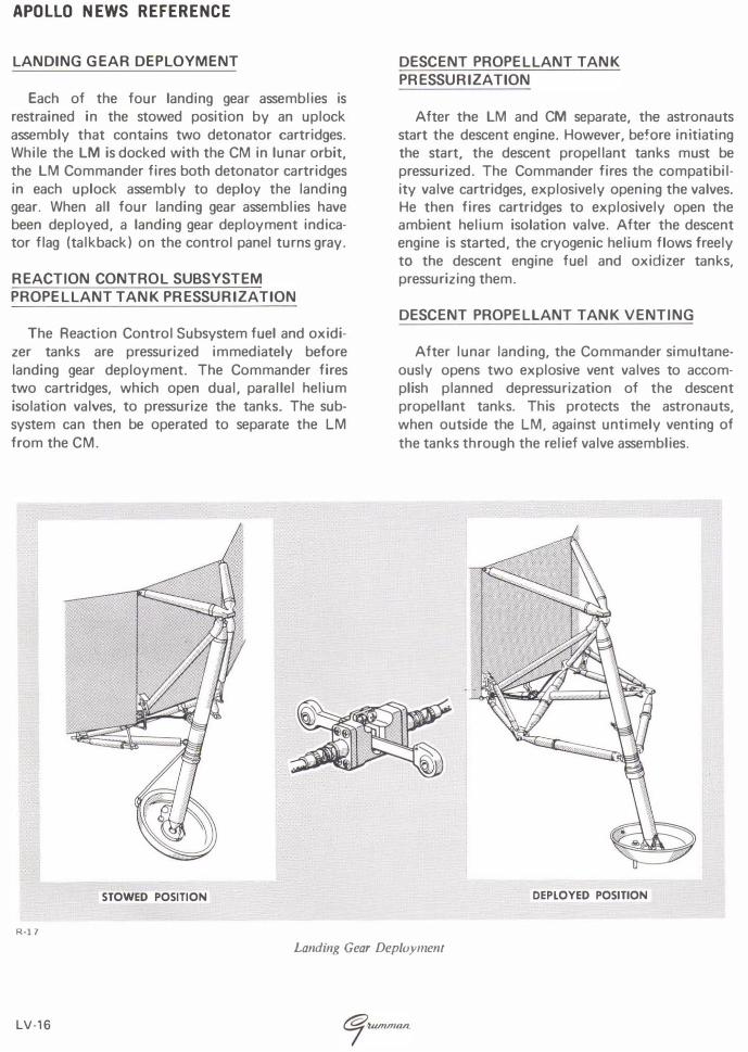
LANDING GEAR DEPLOYMENT
Each of the four landing gear assemblies is restrained in the stowed position by an uplock assembly that contains two detonator cartridges. While the LM is docked with the CM in lunar orbit, the LM Commander fires both detonator cartridges in each uplock assembly to deploy the landing gear. When all four landing gear assemblies have been deployed, a landing gear deployment indicator flag (talkback) on the control panel turns gray.
REACTION CONTROL SUBSYSTEM PROPELLANT TANK PRESSURIZATION
The Reaction Control Subsystem fuel and oxidizer tanks are pressurized immediately before landing gear deployment. The Commander fires two cartridges, which open dual, parallel helium isolation valves, to pressurize the tanks. The subsystem can then be operated to separate the LM from the CM.
STOWED POSITION
R-17
DESCENT PROPELLANT TANK PRESSURIZATION
After the LM and CM separate, the astronauts start the descent engine. However, before initiating the start, the descent propellant tanks must be pressurized. The Commander fires the compatibility valve cartridges, explosively opening the valves. He then fires cartridges to explosively open the ambient helium isolation valve. After the descent engine is started, the cryogenic helium flows freely to the descent engine fuel and oxidizer tanks, pressurizing them.
DESCENT PROPELLANT TANK VENTING
After lunar landing, the Commander simultaneously opens two explosive vent valves to accomplish planned depressurization of the descent propellant tanks. This protects the astronauts, when outside the LM, against untimely venting of the tanks through the relief valve assemblies.
DEPLOYED POSITION
Landing Gear Deployment
LV-16
APOLLO NEWS REFERENCE
ASCENT PROPELLANT TANK PRESSURIZATION
After lunar stay, the astronauts take off from the lunar surface in the ascent stage. This requires pressurization of the ascent propellant tanks shortly before initial start of the ascent engine. To accomplish pressurization, the Commander fires explosive valve cartridges, which simultaneously open helium isolation valves and fuel and oxidizer compatibility valves. This permits helium to pressurize the ascent fuel and oxidizer tanks.
R-18
BEFORE FIRING AFTER FIRING
BOLT ASSEMBLY
BOLT CARTRIDGE ASSEMBLY
Explosive Nuts and Bolts
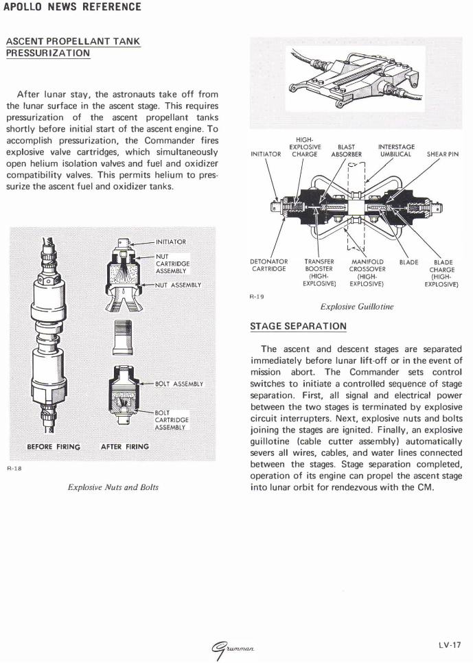
HIGHEXPLOSIVE
INITIATOR CHARGE
DETONATOR CARTRIDGE
R-19
TRANSFER BOOSTER (HIGH
EXPLOSIVE)
BLAST
MANIFOLD CROSSOVER
(HIGHEXPLOSIVE)
Explosive Guillotine
STAGE SEPARATION
SHEAR PIN
BlADE BLADE CHARGE {HIGH
EXPLOSIVE)
The ascent and descent stages are separated immediately before lunar lift-off or in the event of mission abort. The Commander sets control switches to initiate a controlled sequence of stage separation. First, all signal and electrical power between the two stages is terminated by explosive circuit interrupters. Next, explosive nuts and bolts joining the stages are ignited. Finally, an explosive guillotine (cable cutter assembly) automatically severs all wires, cables, and water lines connected between the stages. Stage separation completed, operation of its engine can propel the ascent stage into lunar orbit for rendezvous with the CM.
LV-17