Embed Size (px)
Citation preview
Project Overview & Status
Craig Tooley – LRO Project ManagerCatherine Peddie – LRO Deputy Project
Manager
NASA Goddard Space Flight Centerhttp://lunar.gsfc.nasa.gov/
November 28, 2006
Lunar Reconnaissance Orbiter
Craig Tooley & Cathy Peddie - LRO Project 2
LRO Follows in the Footsteps of the Apollo Robotic Precursors
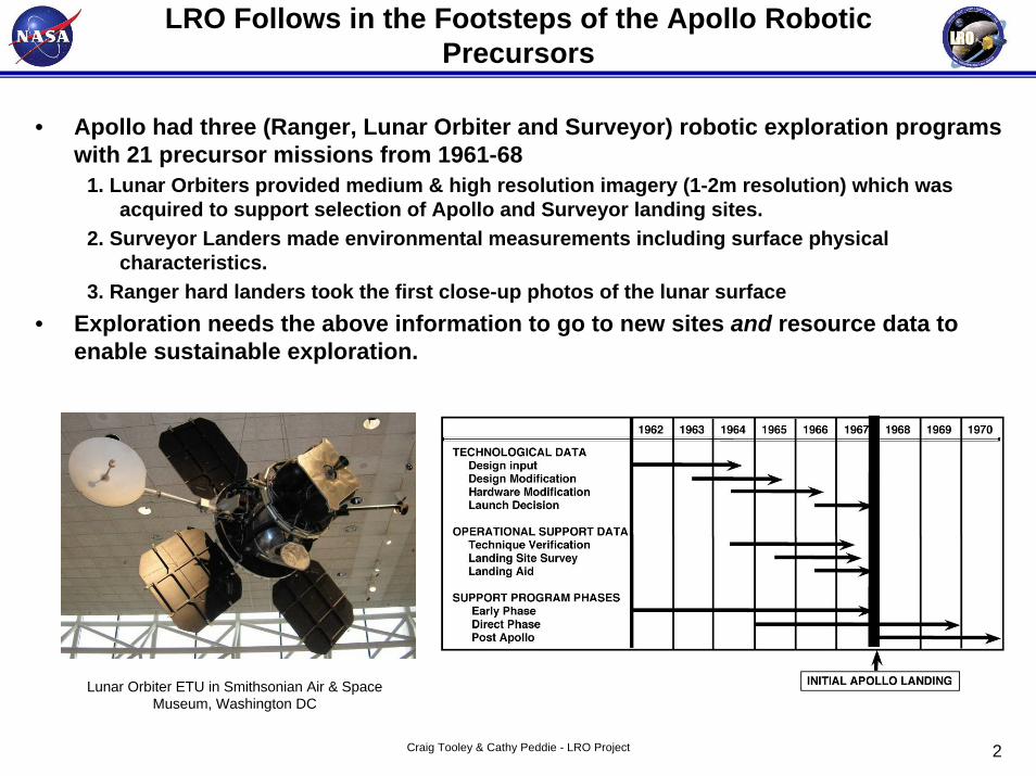
• Apollo had three (Ranger, Lunar Orbiter and Surveyor) robotic exploration programs with 21 precursor missions from 1961-68
1. Lunar Orbiters provided medium & high resolution imagery (1-2m resolution) which was acquired to support selection of Apollo and Surveyor landing sites.
2. Surveyor Landers made environmental measurements including surface physical characteristics.
3. Ranger hard landers took the first close-up photos of the lunar surface• Exploration needs the above information to go to new sites and resource data to
enable sustainable exploration.
Lunar Orbiter ETU in Smithsonian Air & Space Museum, Washington DC
Craig Tooley & Cathy Peddie - LRO Project 3
Luna
Surveyor
Apollo
“Top 10” Lunar Exploration Sites+
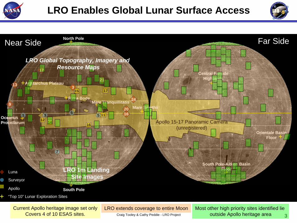
LRO Enables Global Lunar Surface Access
Near Side Far Side
+
+
++
+
+
1112 14
15 17
16
5631
7
24
21
20
17
16
13
9
3Aristarchus Plateau
OceanusProcellarum
Mare TranquillitatisRima Bode
Orientale BasinFloor
+Mare Smythii
+Central Farside
Highlands
South Pole-Aitken BasinFloor
South Pole+
North Pole+
Apollo 15-17 Panoramic Camera(unregistered)
Current Apollo heritage image set onlyCovers 4 of 10 ESAS sites.
LRO Global Topography, Imagery and Resource Maps
LRO 1m Landing Site Images
LRO extends coverage to entire Moon Most other high priority sites identified lie outside Apollo heritage area
Craig Tooley & Cathy Peddie - LRO Project 4
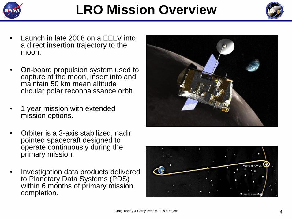
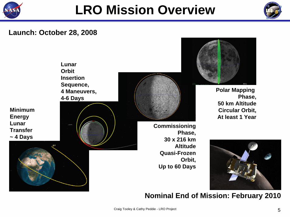
LRO Mission Overview
• Launch in late 2008 on a EELV into a direct insertion trajectory to the moon.
• On-board propulsion system used to capture at the moon, insert into and maintain 50 km mean altitude circular polar reconnaissance orbit.
• 1 year mission with extended mission options.
• Orbiter is a 3-axis stabilized, nadir pointed spacecraft designed to operate continuously during the primary mission.
• Investigation data products delivered to Planetary Data Systems (PDS) within 6 months of primary mission completion.
Craig Tooley & Cathy Peddie - LRO Project 5
MinimumEnergyLunarTransfer~ 4 Days
LunarOrbitInsertionSequence,4 Maneuvers,4-6 Days
Commissioning Phase,
30 x 216 km Altitude
Quasi-Frozen Orbit,
Up to 60 Days
Polar Mapping Phase,
50 km AltitudeCircular Orbit,At least 1 Year
Launch: October 28, 2008
Nominal End of Mission: February 2010
LRO Mission Overview

Craig Tooley & Cathy Peddie - LRO Project 6
LRO Project Implementing Organizations
NASA HQ ESMDLevel 1 Requirements
GSFC LRO ProjectMission ManagementMission Operations
Spacecraft BusGround Data System
NASA MSFC LPRPProgram Management
KSCLaunch Services
(Lockheed Martin)
Boston University/MITCRaTER
Arizona State University/MSSSLROC
GSFCLOLA
Southwest Research InstituteLAMP
UCLA/JPLDiviner
Federal Space Agency of Russia/Russian Institute for Space
ResearchLEND
Naval Air Warfare Command/SOMDMini-RF
Craig Tooley & Cathy Peddie - LRO Project 7
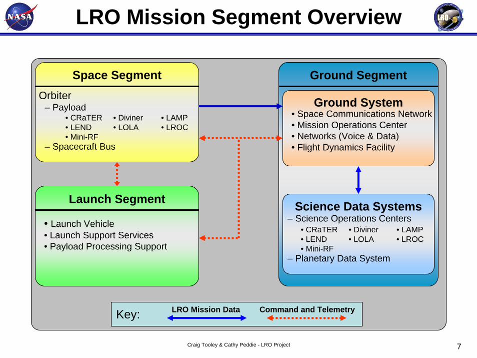
LRO Mission Segment Overview
Launch Segment
• Launch Vehicle• Launch Support Services• Payload Processing Support
Space SegmentOrbiter
– Payload
Key: LRO Mission Data Command and Telemetry
• CRaTER • Diviner • LAMP• LEND • LOLA • LROC• Mini-RF
Ground Segment
Science Data Systems– Science Operations Centers
– Planetary Data System
• CRaTER • Diviner • LAMP• LEND • LOLA • LROC• Mini-RF
Ground System• Space Communications Network• Mission Operations Center• Networks (Voice & Data)• Flight Dynamics Facility– Spacecraft Bus
Craig Tooley & Cathy Peddie - LRO Project 8
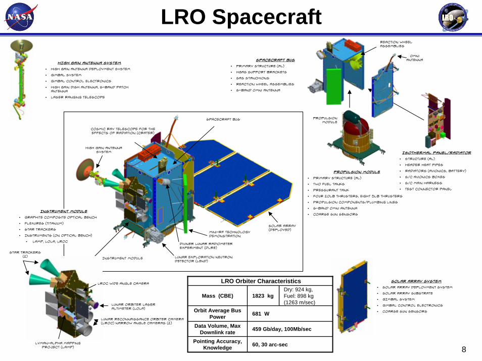
LRO Spacecraft
HIGH Gain Antenna System
• High Gain antenna Deployment System
• Gimbal System
• Gimbal Control Electronics
• High Gain Dish Antenna, S-Band Patch Antenna
• Laser Ranging Telescope
Solar Array System
• Solar Array Deployment System
• Solar Array Substrate
• GIMBAL System
• Gimbal Control Electronics
• Coarse Sun Sensors
Instrument Module
• Graphite Composite Optical Bench
• Flexures (Titanium)
• Star Trackers
• Instruments (on Optical Bench)
• LAMP, LOLA, LROC
Spacecraft Bus
• Primary Structure (Al)
• HGAS Support Brackets
• SAS Stanchions
• Reaction Wheel Assemblies
• S-Band Omni Antenna
Reaction Wheel Assemblies
Omni Antenna
IsoThermal panel/Radiator
• Structure (Al)
• Header heat Pipes
• Radiators (Avionics, Battery)
• S/C Avionics Boxes
• S/C Main Harness
• Test Connector Panel
Propulsion Module
• Primary Structure (Al)
• Two Fuel Tanks
• Pressurant Tank
• four 20lb thrusters, Eight 5lb thrusters
• Propulsion components/plumbing lines
• S-Band Omni Antenna
• Coarse Sun Sensors
Propulsion Module
Solar Array (Deployed)
Lunar Exploration Neutron Detector (LEND)
Mini-RF Technology Demonstration
Instrument Module
High Gain Antenna System
Cosmic Ray Telescope for the Effects of Radiation (CRaTER)
Diviner Lunar Radiometer Experiment (DLRE)
Spacecraft Bus
Lunar Orbiter Laser Altimeter (LOLA)
Lyman-Alpha Mapping Project (LAMP)
Star Trackers (2)
Lunar Reconnaissance Orbiter Camera (LROC) Narrow Angle Cameras (2)
LROC Wide Angle Camera LRO Orbiter Characteristics
Mass (CBE) 1823 kgDry: 924 kg, Fuel: 898 kg (1263 m/sec)
Orbit Average Bus Power 681 W
Data Volume, Max Downlink rate 459 Gb/day, 100Mb/sec
Pointing Accuracy, Knowledge 60, 30 arc-sec
Craig Tooley & Cathy Peddie - LRO Project 9
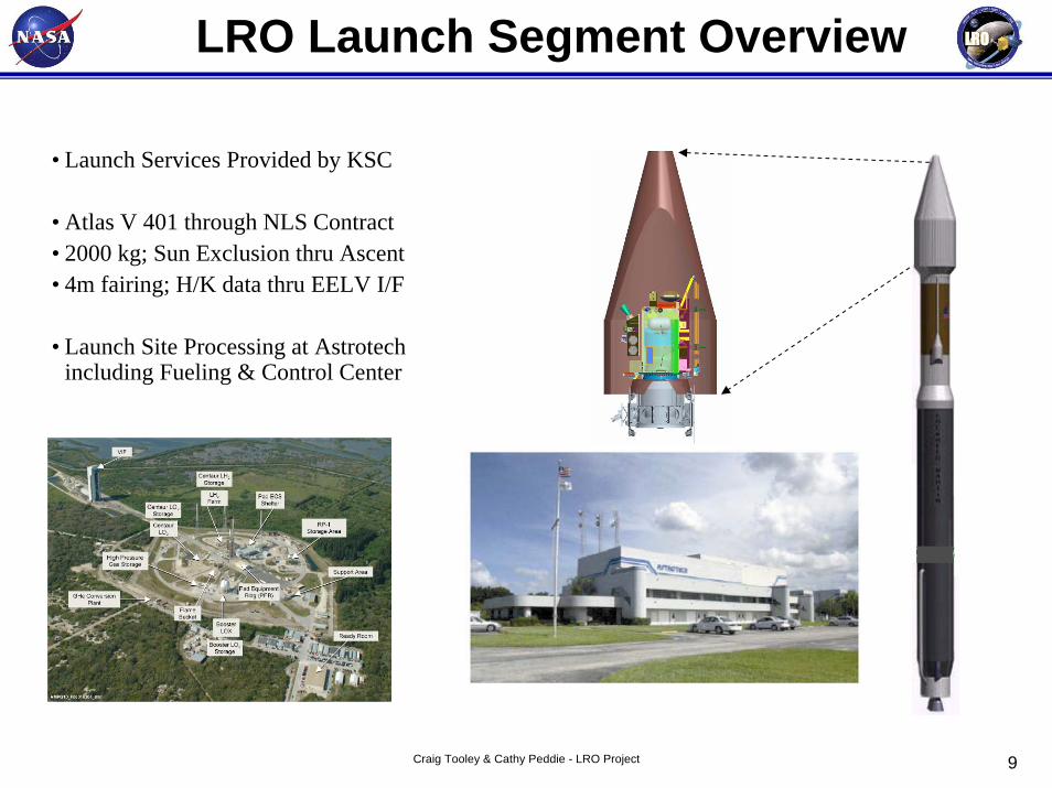
LRO Launch Segment Overview
• Launch Services Provided by KSC
• Atlas V 401 through NLS Contract• 2000 kg; Sun Exclusion thru Ascent• 4m fairing; H/K data thru EELV I/F
• Launch Site Processing at Astrotechincluding Fueling & Control Center
Craig Tooley & Cathy Peddie - LRO Project 10
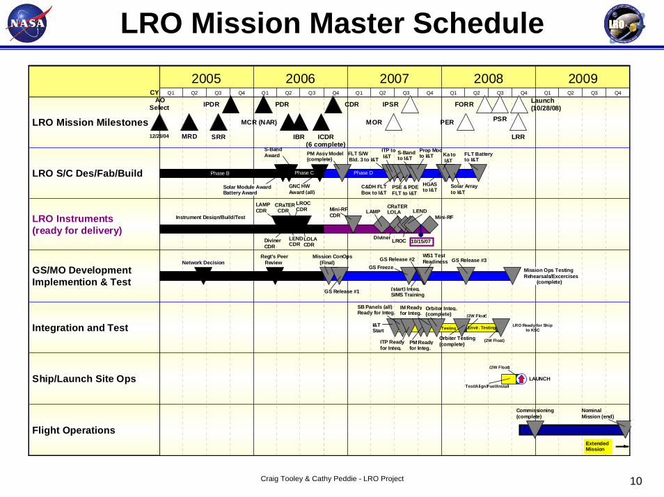
LRO Mission Master Schedule2005 2006 2007 2008 2009
Q1 Q2 Q3 Q4 Q1 Q2 Q3 Q4 Q1 Q2 Q3 Q4 Q1 Q2 Q3 Q4 Q1 Q2 Q3 Q4
LRO Mission Milestones
LRO S/C Des/Fab/Build
LRO Instruments(ready for delivery)
GS/MO DevelopmentImplemention & Test
Integration and Test
Ship/Launch Site Ops
Flight Operations
AOSelect
MRD SRR
IPDR PDR
MCR (NAR)
IBR ICDR (6 complete)
CDR
MOR
IPSR
PER
FORR
PSR
LRR
Launch(10/28/08)
Solar Module AwardBattery Award
FLT Batteryto I&T
Network DecisionRegt's Peer Review
Mission ConOps (Final)
Mission Ops TestingRehearsals/Excercises (complete)
I&T Start
LRO Ready for Ship to KSC
Commissioning(complete)
Nominal Mission (end)
(2W Float)
(2W Float)
CY
Instrument Design/Build/Test
Testing
Test/Align/Fuel/Install
Phase B
ITP toI&T
DivinerCDR
LROCCDR
LENDCDR
CRaTER CDR
LOLACDR
Mini-RFCDR Mini-RF
LAMPCDR
GS Release #1
12/23/04
Diviner
Prop Modto I&T
(2W Float)
GNC HWAward (all)
S-BandAward
Solar Array to I&T
FLT S/W Bld. 3 to I&T
PM Assy Model(complete)
PSE & PDEFLT to I&T
C&DH FLTBox to I&T
S-Bandto I&T
HGAS to I&T
Ka toI&T
Phase C Phase D
CRaTERLOLALAMP
LROC
LEND
10/15/07
WS1 TestReadinessGS Release #2
GS FreezeGS Release #3
(start) Integ.SIMS Training
Extended Mission
SB Panels (all)Ready for Integ.
ITP Readyfor Integ.
IM Readyfor Integ.
PM Ready for Integ.
Orbiter Integ.(complete)
Orbiter Testing(complete)
Envir. Testing
LAUNCH
Lunar Reconnaissance Orbiter (LRO) Mission
Gordon ChinLRO Project Scientist
NASA Goddard Space Flight Center (GSFC)LRO Project Science Working Group
East West CenterUniversity of Hawaii Manoa
Honolulu, HawaiiNovember 28, 2006
Craig TooleyGSFC
Project Manager Arlin BartelsGSFC
John KellerGSFC
Deputy Project Scientist
Igor MitrofanovIKI Moscow
LEND PI
Keith RaneyAPL
David SmithGSFC
Alan SternSWRI
David PaigeUCLA
Mark RobinsonNorthwest U
Harlan SpenceBoston U
Instrument Manager
DLRE PI Mini-RF POC
LOLA PI
LAMP PI
LROC PI
CRaTER PI
Gordon Chin - LRO Project 12
Instrument & Mission Details
• LRO Instrument and Mission details have been input into a Space Science Review Paper, currently being reviewed prior to publication, and will be available for a pre-print viewing at the December AGU meeting
• In addition, the paper will be posted on the LRO website later this year
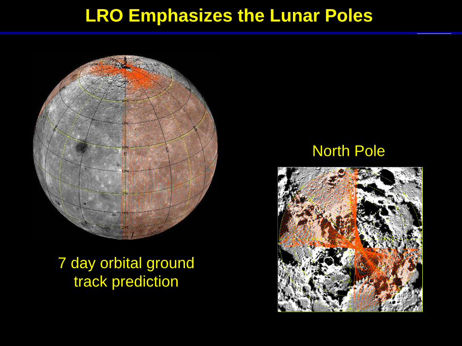
North Pole
LRO Emphasizes the Lunar Poles
7 day orbital ground track prediction
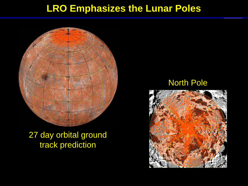
North Pole
27 day orbital ground track prediction
LRO Emphasizes the Lunar Poles
Gordon Chin - LRO Project 15
Opportunities
• Low Polar orbit will saturate the polar regions with measurement coverage at high to moderation spatial resolution observations– What is the complementary nature of all lunar mission data at the
Poles?– How does preceding mission data inform near-term future
missions?• At the equator LRO ground track will have, on average,
1.2 km (average) gaps– How can other mission data fill in gaps; e.g. laser altimetry,
imagery, etc.?
Gordon Chin - LRO Project 16
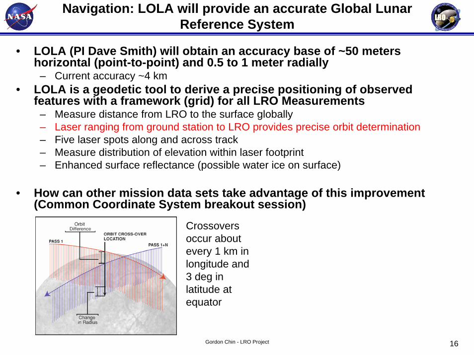
Navigation: LOLA will provide an accurate Global Lunar Reference System
• LOLA (PI Dave Smith) will obtain an accuracy base of ~50 meters horizontal (point-to-point) and 0.5 to 1 meter radially
– Current accuracy ~4 km• LOLA is a geodetic tool to derive a precise positioning of observed
features with a framework (grid) for all LRO Measurements– Measure distance from LRO to the surface globally– Laser ranging from ground station to LRO provides precise orbit determination– Five laser spots along and across track– Measure distribution of elevation within laser footprint– Enhanced surface reflectance (possible water ice on surface)
• How can other mission data sets take advantage of this improvement (Common Coordinate System breakout session)
Crossovers occur about every 1 km in longitude and 3 deg in latitude at equator
Gordon Chin - LRO Project 17
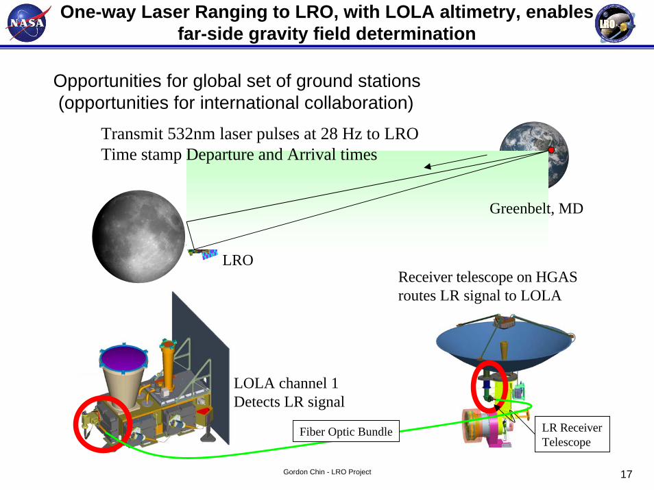
One-way Laser Ranging to LRO, with LOLA altimetry, enables far-side gravity field determination
LRO
Greenbelt, MD
� Transmit 532nm laser pulses at 28 Hz to LRO� Time stamp Departure and Arrival times
Receiver telescope on HGASroutes LR signal to LOLA
LOLA channel 1Detects LR signal
LR ReceiverTelescope
Fiber Optic Bundle
Opportunities for global set of ground stations(opportunities for international collaboration)
Gordon Chin - LRO Project 18
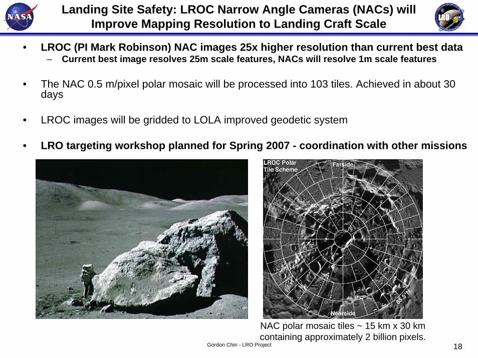
Landing Site Safety: LROC Narrow Angle Cameras (NACs) will Improve Mapping Resolution to Landing Craft Scale
• LROC (PI Mark Robinson) NAC images 25x higher resolution than current best data– Current best image resolves 25m scale features, NACs will resolve 1m scale features
• The NAC 0.5 m/pixel polar mosaic will be processed into 103 tiles. Achieved in about 30 days
• LROC images will be gridded to LOLA improved geodetic system
• LRO targeting workshop planned for Spring 2007 - coordination with other missions
.
NAC polar mosaic tiles ~ 15 km x 30 km containing approximately 2 billion pixels.
Gordon Chin - LRO Project 19
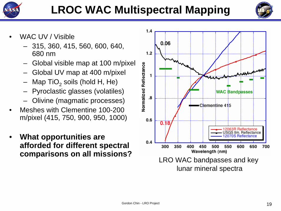
LROC WAC Multispectral Mapping
• WAC UV / Visible– 315, 360, 415, 560, 600, 640,
680 nm– Global visible map at 100 m/pixel – Global UV map at 400 m/pixel– Map TiO2 soils (hold H, He)– Pyroclastic glasses (volatiles)– Olivine (magmatic processes)
• Meshes with Clementine 100-200 m/pixel (415, 750, 900, 950, 1000)
• What opportunities are afforded for different spectral comparisons on all missions?
LRO WAC bandpasses and key lunar mineral spectra
Gordon Chin - LRO Project 20
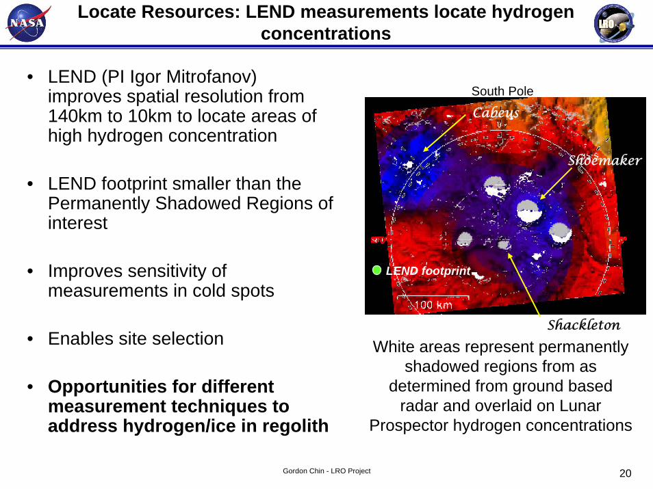
Locate Resources: LEND measurements locate hydrogen concentrations
• LEND (PI Igor Mitrofanov) improves spatial resolution from 140km to 10km to locate areas of high hydrogen concentration
• LEND footprint smaller than the Permanently Shadowed Regions of interest
• Improves sensitivity of measurements in cold spots
• Enables site selection
• Opportunities for different measurement techniques to address hydrogen/ice in regolith
South Pole
Cabeus
Shoemaker
Shackleton
White areas represent permanently shadowed regions from as
determined from ground based radar and overlaid on Lunar
Prospector hydrogen concentrations
LEND footprint
Gordon Chin - LRO Project 21
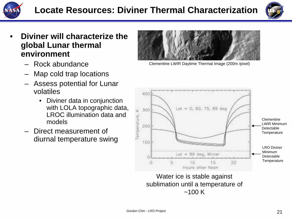
Locate Resources: Diviner Thermal Characterization
• Diviner will characterize the global Lunar thermal environment– Rock abundance– Map cold trap locations– Assess potential for Lunar
volatiles• Diviner data in conjunction
with LOLA topographic data, LROC illumination data and models
– Direct measurement of diurnal temperature swing
Clementine LWIR Daytime Thermal Image (200m /pixel)
Clementine LWIR Minimum Detectable Temperature
LRO Diviner Minimum Detectable Temperature
Water ice is stable against sublimation until a temperature of
~100 K
Gordon Chin - LRO Project 22
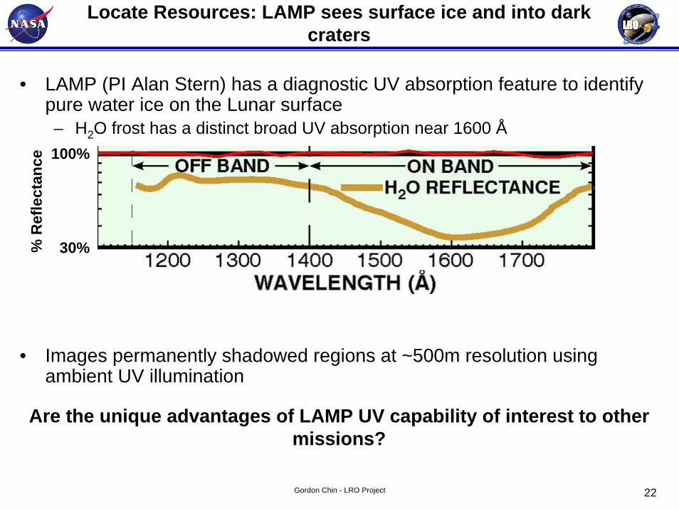
Locate Resources: LAMP sees surface ice and into dark craters
• LAMP (PI Alan Stern) has a diagnostic UV absorption feature to identify pure water ice on the Lunar surface– H2O frost has a distinct broad UV absorption near 1600 Å
• Images permanently shadowed regions at ~500m resolution using ambient UV illumination
30%
100%
% R
efle
ctan
ce
Are the unique advantages of LAMP UV capability of interest to other missions?
Gordon Chin - LRO Project 23
Life in Space Environment
• CRaTER (PI Harlan Spence) will measure the Linear Energy Transfer (LET) spectra behind tissue equivalent material– LET spectra is the missing link connecting Galactic Cosmic Rays
and Solar Energetic Particles to potential tissue damage
• LEND contributes by providing knowledge of the neutron radiation environment
• What synergy arises from the cross-pollination of all radiation measurements have? - e.g. longer span of coverage through a solar cycle
Gordon Chin - LRO Project 24
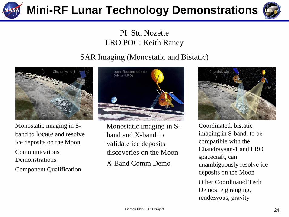
Mini-RF Lunar Technology Demonstrations
Chandrayaan-1 Lunar Reconnaissance Orbiter (LRO)
Monostatic imaging in S-band and X-band to validate ice deposits discoveries on the MoonX-Band Comm Demo
Chandrayaan-1
LRO
PI: Stu NozetteLRO POC: Keith Raney
SAR Imaging (Monostatic and Bistatic)
Monostatic imaging in S-band to locate and resolve ice deposits on the Moon.Communications DemonstrationsComponent Qualification
Coordinated, bistaticimaging in S-band, to be compatible with the Chandrayaan-1 and LRO spacecraft, can unambiguously resolve ice deposits on the MoonOther Coordinated Tech Demos: e.g ranging, rendezvous, gravity
Gordon Chin - LRO Project 25
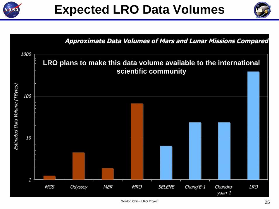
Expected LRO Data Volumes
LRO plans to make this data volume available to the international scientific community
Gordon Chin - LRO Project 26
International Lunar Missions: Possibilities of Cross Cultural and International EPO
• Introduction and acknowledgement of present EPO leads• The opportunity to engage a world wide population with the current
global lunar exploration effort is extraordinary• The impact of this new era in lunar exploration can also be seen in light
of historical analogs to ages of exploration – and the impact the new era can have in motivating youths around the world
• Education and Public Outreach (EPO) should be an important dimension of LRO, and all missions– The NASA Exploration Mission Systems Directorate (ESMD), Lunar
Precursor Robotic Program (LPRP) and LRO will need to implement an integrated strategy for seizing this unique opportunity
– We are drawing on NASA’s Science Missions Directorate (SMD) experiences by leveraging its strengths in advancing EPO as an integral part of a NASA mission
– We are introducing an opportunity to develop international EPO collaborations at the breakout tomorrow afternoon