Embed Size (px)
Citation preview
GENERAL ILLUMINATION
AB113 LUXEON S Application Brief ©2015 Lumileds Holding B.V. All rights reserved.
LUXEON SAssembly and handling information
IntroductionThis application brief addresses the recommended assembly and handling procedures for LUXEON s2000, LUXEON s3000, and LUXEON s5000 array emitters. Proper assembly, handling, and thermal management, as outlined in this application brief, ensure high optical output and long lumen maintenance for these LUXEON emitters.
ScopeThe assembly and handling guidelines in this application brief apply to the following LUXEON S products:
LUXEON s2000 LUXEON s2000N
LUXEON s3000 LUXEON s3000N
LUXEON s5000 LUXEON s5000N
In the remainder of this document the term LUXEON S emitter refers to any product in the LUXEON S product series listed above. Any handling requirements that are specific to a subset of LUXEON S emitters will be clearly marked.
AB113 LUXEON S Application Brief 20150330 ©2015 Lumileds Holding B.V. All rights reserved. 2
Table of Contents
Introduction . . . . . . . . . . . . . . . . . . . . . . . . . . . . . . . . . . . . . . . . . . . . . . . . . . . . . . . . . . . . . . . . . . . . . . . . . . .1
Scope . . . . . . . . . . . . . . . . . . . . . . . . . . . . . . . . . . . . . . . . . . . . . . . . . . . . . . . . . . . . . . . . . . . . . . . . . . . . . . . . .1
1 . Component . . . . . . . . . . . . . . . . . . . . . . . . . . . . . . . . . . . . . . . . . . . . . . . . . . . . . . . . . . . . . . . . . . . . . . . .3
1.1 Description . . . . . . . . . . . . . . . . . . . . . . . . . . . . . . . . . . . . . . . . . . . . . . . . . . . . . . . . . . . . . . . . . . . . . . . . .3
1.2 Optical Center . . . . . . . . . . . . . . . . . . . . . . . . . . . . . . . . . . . . . . . . . . . . . . . . . . . . . . . . . . . . . . . . . . . . . . .4
1.3 Handling Precautions . . . . . . . . . . . . . . . . . . . . . . . . . . . . . . . . . . . . . . . . . . . . . . . . . . . . . . . . . . . . . . . . .4
1.4 Cleaning . . . . . . . . . . . . . . . . . . . . . . . . . . . . . . . . . . . . . . . . . . . . . . . . . . . . . . . . . . . . . . . . . . . . . . . . . . . .4
1.5 Electrical Isolation . . . . . . . . . . . . . . . . . . . . . . . . . . . . . . . . . . . . . . . . . . . . . . . . . . . . . . . . . . . . . . . . . . . .5
1.6 Mechanical Files. . . . . . . . . . . . . . . . . . . . . . . . . . . . . . . . . . . . . . . . . . . . . . . . . . . . . . . . . . . . . . . . . . . . . .5
1.7 Soldering. . . . . . . . . . . . . . . . . . . . . . . . . . . . . . . . . . . . . . . . . . . . . . . . . . . . . . . . . . . . . . . . . . . . . . . . . . . .5
2 . Assembly Process . . . . . . . . . . . . . . . . . . . . . . . . . . . . . . . . . . . . . . . . . . . . . . . . . . . . . . . . . . . . . . . . . . .6
2.1 Mounting LUXEON S onto a Heat Sink . . . . . . . . . . . . . . . . . . . . . . . . . . . . . . . . . . . . . . . . . . . . . . . . . .6
2.2 Soldering Electrical Connections on the LUXEON S . . . . . . . . . . . . . . . . . . . . . . . . . . . . . . . . . . . . . .10
3 . Thermal Management . . . . . . . . . . . . . . . . . . . . . . . . . . . . . . . . . . . . . . . . . . . . . . . . . . . . . . . . . . . . . .11
3.1 Thermal Interface Materials (TIM) Selection . . . . . . . . . . . . . . . . . . . . . . . . . . . . . . . . . . . . . . . . . . . . .11
3.2 Heat Sink. . . . . . . . . . . . . . . . . . . . . . . . . . . . . . . . . . . . . . . . . . . . . . . . . . . . . . . . . . . . . . . . . . . . . . . . . . .11
4 . Thermal Measurement Guidelines . . . . . . . . . . . . . . . . . . . . . . . . . . . . . . . . . . . . . . . . . . . . . . . . . . . .11
4.1 Introduction . . . . . . . . . . . . . . . . . . . . . . . . . . . . . . . . . . . . . . . . . . . . . . . . . . . . . . . . . . . . . . . . . . . . . . . .11
4.2 Junction Temperature Estimation Based on Temperature Readings for Ts . . . . . . . . . . . . . . . . . . . . . 12
4.3 Junction Temperature Approximation Based on Temperature Readings with the NTC . . . . . . .13
5 . Packaging Considerations — Chemical Compatibility . . . . . . . . . . . . . . . . . . . . . . . . . . . . . . . . . . . .14
About Lumileds . . . . . . . . . . . . . . . . . . . . . . . . . . . . . . . . . . . . . . . . . . . . . . . . . . . . . . . . . . . . . . . . . . . . . . .16
AB113 LUXEON S Application Brief 20150330 ©2015 Lumileds Holding B.V. All rights reserved. 3
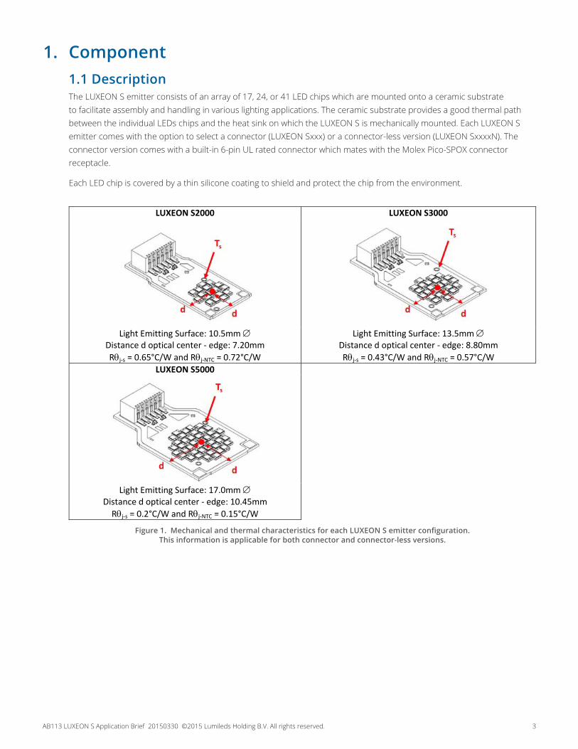
1. Component1.1 Description The LUXEON S emitter consists of an array of 17, 24, or 41 LED chips which are mounted onto a ceramic substrate to facilitate assembly and handling in various lighting applications. The ceramic substrate provides a good thermal path between the individual LEDs chips and the heat sink on which the LUXEON S is mechanically mounted. Each LUXEON S emitter comes with the option to select a connector (LUXEON Sxxx) or a connector-less version (LUXEON SxxxxN). The connector version comes with a built-in 6-pin UL rated connector which mates with the Molex Pico-SPOX connector receptacle.
Each LED chip is covered by a thin silicone coating to shield and protect the chip from the environment.
LUXEON S2000 LUXEON S3000
Light Emitting Surface: 10.5mm Distance d optical center - edge: 7.20mm Rj-s = 0.65°C/W and Rj-NTC = 0.72°C/W
Light Emitting Surface: 13.5mm Distance d optical center - edge: 8.80mm Rj-s = 0.43°C/W and Rj-NTC = 0.57°C/W
LUXEON S5000
Light Emitting Surface: 17.0mm Distance d optical center - edge: 10.45mm
Rj-s = 0.2°C/W and Rj-NTC = 0.15°C/W Figure 1. Mechanical and thermal characteristics for each LUXEON S emitter configuration.
This information is applicable for both connector and connector-less versions.
AB113 LUXEON S Application Brief 20150330 ©2015 Lumileds Holding B.V. All rights reserved. 4
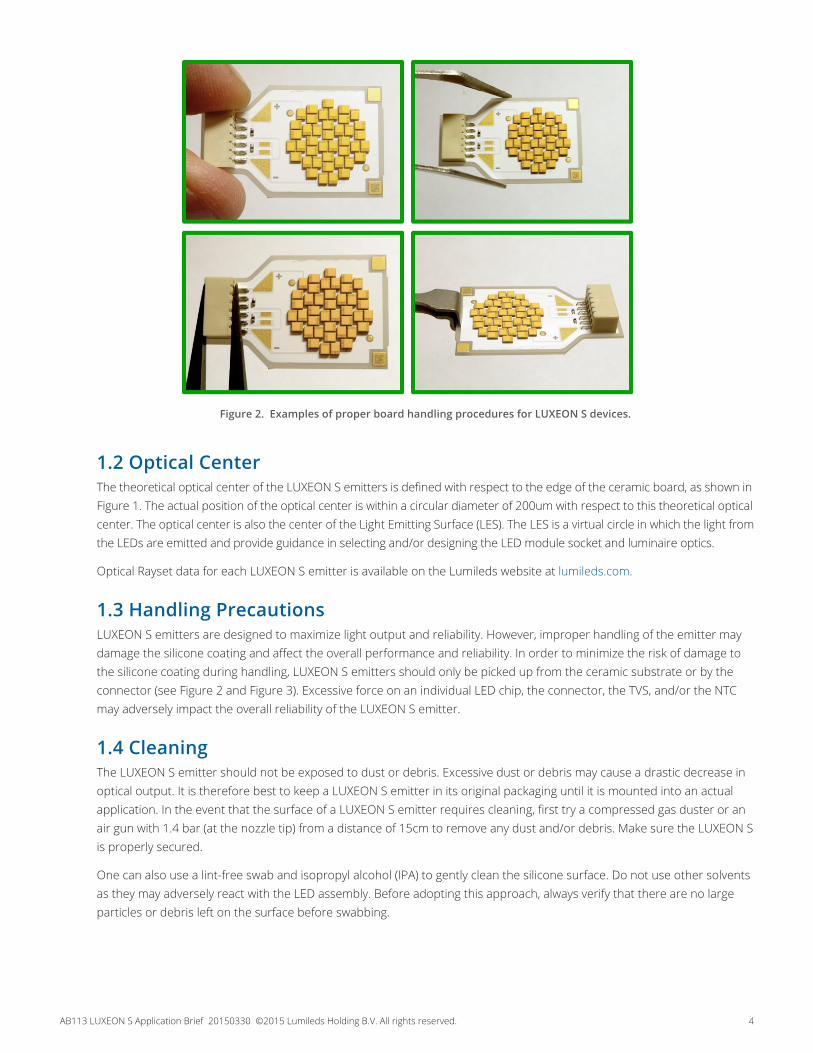
Figure 2. Examples of proper board handling procedures for LUXEON S devices.
1.2 Optical CenterThe theoretical optical center of the LUXEON S emitters is defined with respect to the edge of the ceramic board, as shown in Figure 1. The actual position of the optical center is within a circular diameter of 200um with respect to this theoretical optical center. The optical center is also the center of the Light Emitting Surface (LES). The LES is a virtual circle in which the light from the LEDs are emitted and provide guidance in selecting and/or designing the LED module socket and luminaire optics.
Optical Rayset data for each LUXEON S emitter is available on the Lumileds website at lumileds.com.
1.3 Handling PrecautionsLUXEON S emitters are designed to maximize light output and reliability. However, improper handling of the emitter may damage the silicone coating and affect the overall performance and reliability. In order to minimize the risk of damage to the silicone coating during handling, LUXEON S emitters should only be picked up from the ceramic substrate or by the connector (see Figure 2 and Figure 3). Excessive force on an individual LED chip, the connector, the TVS, and/or the NTC may adversely impact the overall reliability of the LUXEON S emitter.
1.4 CleaningThe LUXEON S emitter should not be exposed to dust or debris. Excessive dust or debris may cause a drastic decrease in optical output. It is therefore best to keep a LUXEON S emitter in its original packaging until it is mounted into an actual application. In the event that the surface of a LUXEON S emitter requires cleaning, first try a compressed gas duster or an air gun with 1.4 bar (at the nozzle tip) from a distance of 15cm to remove any dust and/or debris. Make sure the LUXEON S is properly secured.
One can also use a lint-free swab and isopropyl alcohol (IPA) to gently clean the silicone surface. Do not use other solvents as they may adversely react with the LED assembly. Before adopting this approach, always verify that there are no large particles or debris left on the surface before swabbing.
AB113 LUXEON S Application Brief 20150330 ©2015 Lumileds Holding B.V. All rights reserved. 5
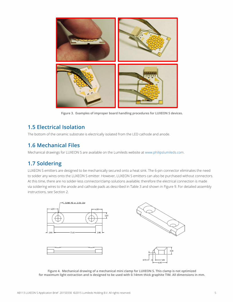
Figure 3. Examples of improper board handling procedures for LUXEON S devices.
1.5 Electrical IsolationThe bottom of the ceramic substrate is electrically isolated from the LED cathode and anode.
1.6 Mechanical FilesMechanical drawings for LUXEON S are available on the Lumileds website at www.philipslumileds.com.
1.7 SolderingLUXEON S emitters are designed to be mechanically secured onto a heat sink. The 6-pin connector eliminates the need to solder any wires onto the LUXEON S emitter. However, LUXEON S emitters can also be purchased without connectors. At this time, there are no solder-less connector/clamp solutions available; therefore the electrical connection is made via soldering wires to the anode and cathode pads as described in Table 3 and shown in Figure 9. For detailed assembly instructions, see Section 2.
Figure 4. Mechanical drawing of a mechanical mini clamp for LUXEON S. This clamp is not optimized for maximum light extraction and is designed to be used with 0.14mm thick graphite TIM. All dimensions in mm.

AB113 LUXEON S Application Brief 20150330 ©2015 Lumileds Holding B.V. All rights reserved. 6
2. Assembly ProcessLUXEON S emitters are designed to be mechanically mounted onto a heat sink, facilitating the design and assembly of various illumination applications. Figure 4 shows the mechanical design of a mini clamp for prototype applications. Each LUXEON S emitter should be secured with two of these clamps onto a heat sink. The drill hole pattern for this mini clamp design varies with the size of the LUXEON S emitter, as shown in Figure 5.
2.1 Mounting LUXEON S onto a Heat SinkTo properly secure a LUXEON S emitter onto a heat sink, follow these steps (see also Figure 6 and Figure 7):
1. Select an appropriate heat sink. Section 3.2 provides guidelines on the appropriate heat sink design.
2. Drill and tap the heat sink for the clamping system to be used.
3. Ensure that the heat sink surface is clean and flat (≤ 25μm), with no crowns or peaks in the mounting area; crowns or peaks on the heat sink surface may adversely impact the thermal conductance between the LUXEON S emitter and the heat sink.
4. Wipe the heat sink surface clean with isopropyl alcohol (IPA).
5. Apply a thermal interface material (TIM) onto the heat sink. If a graphite sheet is used as TIM, cut the sheet to size such that it covers the whole footprint of the LUXEON S emitter. For more details regarding suitable TIMs, see Section 3.1.
6. Carefully place the LUXEON S onto the heat sink.
7. Position the clamp or clamps loosely and install appropriate screws.
8. Ensure that the LUXEON S device is properly positioned in the clamp or clamps.
9. Tighten each screw gradually in a alternating pattern until screws are finger tight.
10. Torque screws to the specified torque (1.8kg/cm).
11. Insert the wire harness connector until it locks into position.
LUXEON S2000 LUXEON S3000 LUXEON S5000
Figure 5. Reference layout and dimensions of the holes which should be drilled into the heat sink to secure LUXEON S with
two mini clamps onto a heat sink. The marker between the clamps corresponds to the theoretical optical center of LUXEON S if the edge of the ceramic board opposite the electrical connector is flush with the edge of the clamps. All dimensions in mm.
AB113 LUXEON S Application Brief 20150330 ©2015 Lumileds Holding B.V. All rights reserved. 7
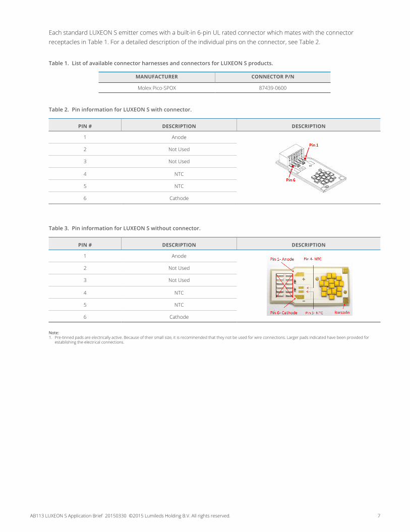
Each standard LUXEON S emitter comes with a built-in 6-pin UL rated connector which mates with the connector receptacles in Table 1. For a detailed description of the individual pins on the connector, see Table 2.
Table 1. List of available connector harnesses and connectors for LUXEON S products.
MANUFACTURER CONNECTOR P/N
Molex Pico-SPOX 87439-0600
Table 2. Pin information for LUXEON S with connector.
PIN # DESCRIPTION DESCRIPTION
1 Anode
2 Not Used
3 Not Used
4 NTC
5 NTC
6 Cathode
Table 3. Pin information for LUXEON S without connector.
PIN # DESCRIPTION DESCRIPTION
1 Anode
2 Not Used
3 Not Used
4 NTC
5 NTC
6 Cathode
Note: 1. Pre-tinned pads are electrically active. Because of their small size, it is recommended that they not be used for wire connections. Larger pads indicated have been provided for
establishing the electrical connections.
AB113 LUXEON S Application Brief 20150330 ©2015 Lumileds Holding B.V. All rights reserved. 8
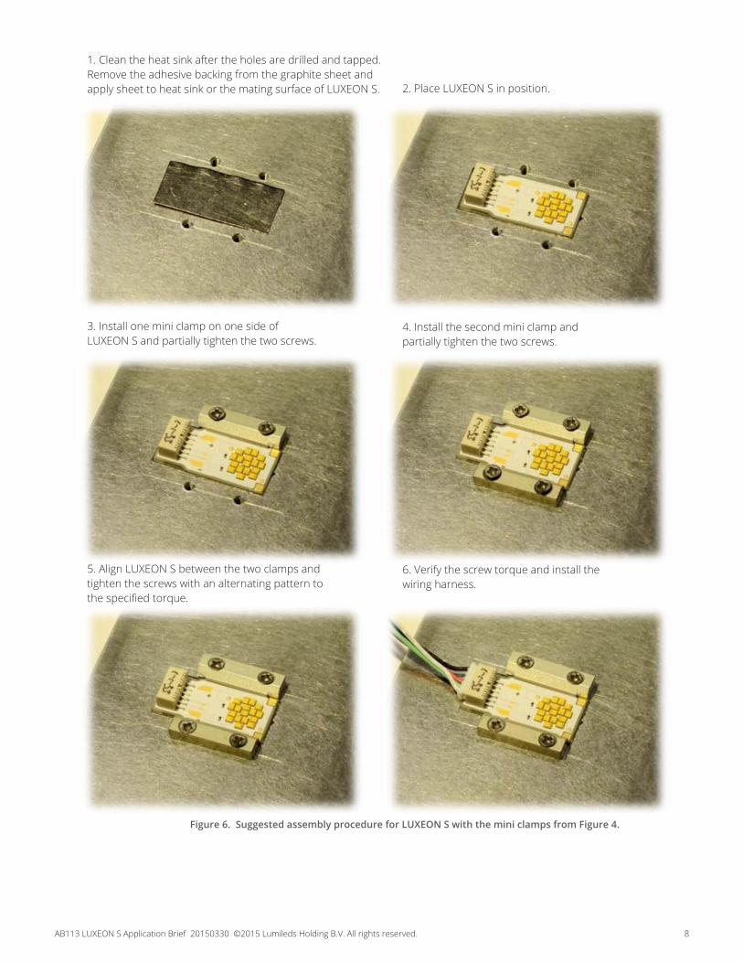
Figure 6. Suggested assembly procedure for LUXEON S with the mini clamps from Figure 4.
1. Clean the heat sink after the holes are drilled and tapped. Remove the adhesive backing from the graphite sheet and apply sheet to heat sink or the mating surface of LUXEON S. 2. Place LUXEON S in position.
3. Install one mini clamp on one side of LUXEON S and partially tighten the two screws.
4. Install the second mini clamp and partially tighten the two screws.
5. Align LUXEON S between the two clamps and tighten the screws with an alternating pattern to the specified torque.
6. Verify the screw torque and install the wiring harness.
AB113 LUXEON S Application Brief 20150330 ©2015 Lumileds Holding B.V. All rights reserved. 9
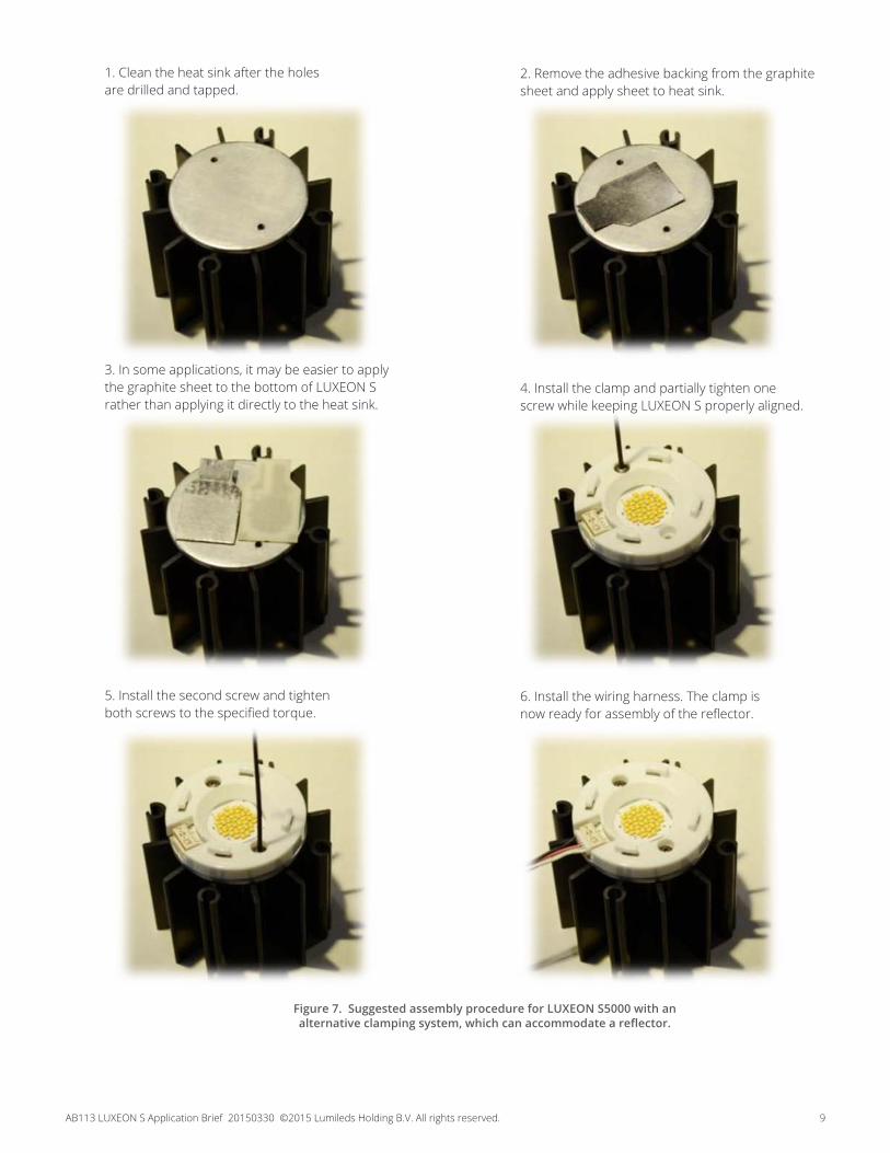
Figure 7. Suggested assembly procedure for LUXEON S5000 with an alternative clamping system, which can accommodate a reflector.
1. Clean the heat sink after the holes are drilled and tapped.
2. Remove the adhesive backing from the graphite sheet and apply sheet to heat sink.
3. In some applications, it may be easier to apply the graphite sheet to the bottom of LUXEON S rather than applying it directly to the heat sink.
4. Install the clamp and partially tighten one screw while keeping LUXEON S properly aligned.
5. Install the second screw and tighten both screws to the specified torque.
6. Install the wiring harness. The clamp is now ready for assembly of the reflector.
AB113 LUXEON S Application Brief 20150330 ©2015 Lumileds Holding B.V. All rights reserved. 10
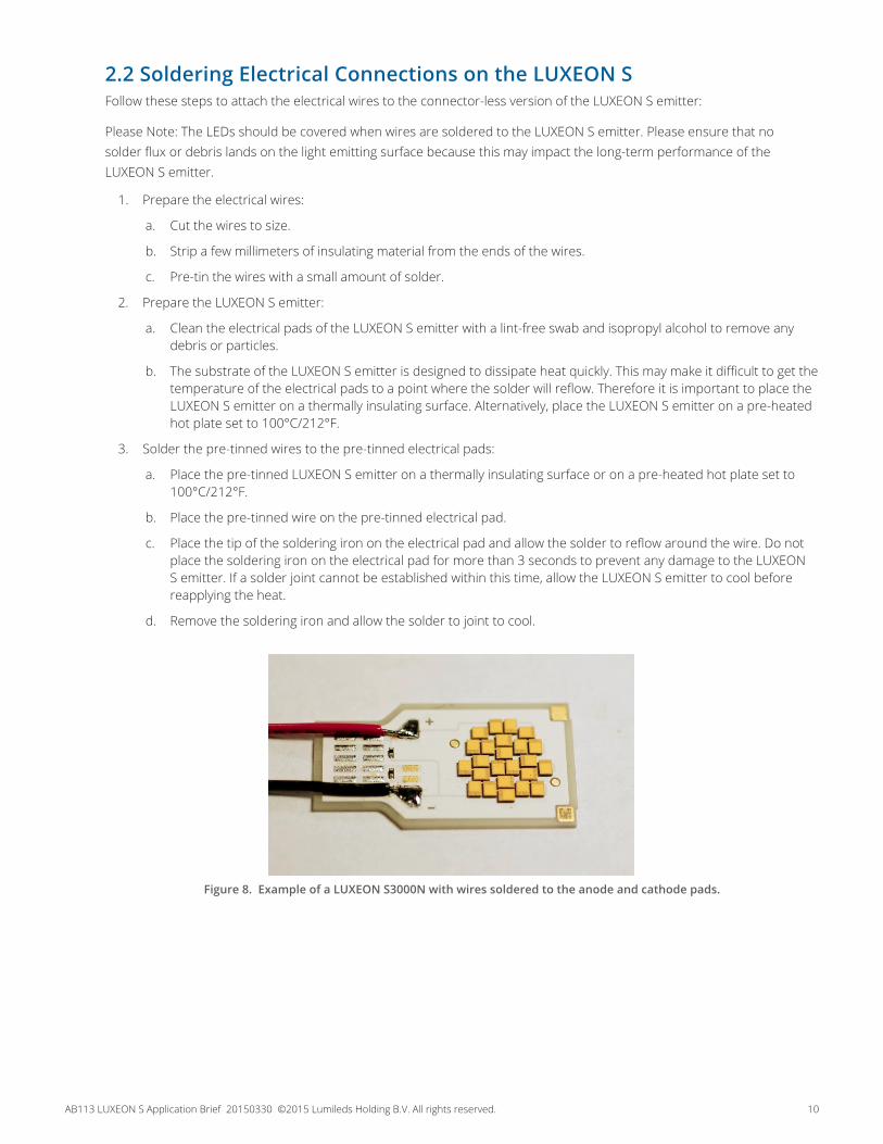
2.2 Soldering Electrical Connections on the LUXEON SFollow these steps to attach the electrical wires to the connector-less version of the LUXEON S emitter:
Please Note: The LEDs should be covered when wires are soldered to the LUXEON S emitter. Please ensure that no solder flux or debris lands on the light emitting surface because this may impact the long-term performance of the LUXEON S emitter.
1. Prepare the electrical wires:
a. Cut the wires to size.
b. Strip a few millimeters of insulating material from the ends of the wires.
c. Pre-tin the wires with a small amount of solder.
2. Prepare the LUXEON S emitter:
a. Clean the electrical pads of the LUXEON S emitter with a lint-free swab and isopropyl alcohol to remove any debris or particles.
b. The substrate of the LUXEON S emitter is designed to dissipate heat quickly. This may make it difficult to get the temperature of the electrical pads to a point where the solder will reflow. Therefore it is important to place the LUXEON S emitter on a thermally insulating surface. Alternatively, place the LUXEON S emitter on a pre-heated hot plate set to 100°C/212°F.
3. Solder the pre-tinned wires to the pre-tinned electrical pads:
a. Place the pre-tinned LUXEON S emitter on a thermally insulating surface or on a pre-heated hot plate set to 100°C/212°F.
b. Place the pre-tinned wire on the pre-tinned electrical pad.
c. Place the tip of the soldering iron on the electrical pad and allow the solder to reflow around the wire. Do not place the soldering iron on the electrical pad for more than 3 seconds to prevent any damage to the LUXEON S emitter. If a solder joint cannot be established within this time, allow the LUXEON S emitter to cool before reapplying the heat.
d. Remove the soldering iron and allow the solder to joint to cool.
Figure 8. Example of a LUXEON S3000N with wires soldered to the anode and cathode pads.

AB113 LUXEON S Application Brief 20150330 ©2015 Lumileds Holding B.V. All rights reserved. 11
Table 4. List of TIM materials that meet the TIM considerations outlined in this section. Note, though, that the actual performance of these TIM materials will depend on the final application.
MANUFACTURER TIMArctic Silver® Arctic Silver® #5
GrafTech Graphite Sheet 1205
3. Thermal Management3.1 Thermal Interface Materials (TIM) SelectionDue to the low thermal resistance of the LUXEON S emitter and its large thermal footprint, a variety of thermal interface materials can be used to thermally connect the emitter to the heat sink (e.g. phase change materials, thermal tapes, graphite sheets).
However, TIM selection should be made with the following considerations:
1. Pump out—Some TIMs will move out of the thermal path during extreme temperature excursions and create voids in the thermal path. These materials should not be used.
2. TIM thickness—Excessive thickness of some TIMs will present an unacceptable thermal resistance even though the thermal conductivity of the material may be high.
3. Surface roughness—In order to fill the air gaps between adjacent surfaces, choose the appropriate TIM that minimizes the interfacial contact resistance.
4. Operating temperature—Some TIMs perform poorly at elevated temperatures. Care should be exercised to select a TIM that will perform well under the anticipated operating conditions.
5. Out-gassing—Out-gassing of some TIMs at design temperatures may produce undesirable optical or appearance qualities (e.g. fogging) in a sealed system. Special consideration must be given to limit this effect.
6. Clamping force—TIMs such as thermal tape or pads perform better when the right pressure is applied.
Table 4 lists several TIMs which Lumileds has successfully used in the past to ensure a good transfer of heat between a PCB and a heat sink. This data is provided for informational purposes only. Lumileds cannot guarantee the performance of the listed TIMs since LED operating conditions will vary with the application design.
3.2 Heat SinkLUXEON S emitters must be mounted onto a properly sized heat sink in order to keep the junction temperature below the maximum acceptable junction temperature specified in the datasheet. For reference, Table 5 summarizes the approximate junction temperature which was measured for each LUXEON S emitter at multiple drive currents on various actively cooled heat sinks. The results in this table were obtained in an open environment with an ambient temperature of approximately 25°C. All Nuventix SynJet® Coolers were configured for maximum cooling in DC mode and were placed on a flat horizontal surface. Actual results may vary with orientation, ambient temperature, and thermal interface material between the LUXEON S emitter and the heat sink.
4. Thermal Measurement Guidelines4.1 IntroductionThis section provides general guidelines on how to determine the junction temperature of a single standalone LUXEON S emitter in order to verify that the junction temperature in the actual application during regular operation does not exceed the maximum allowable temperature specified in the datasheet.
AB113 LUXEON S Application Brief 20150330 ©2015 Lumileds Holding B.V. All rights reserved. 12
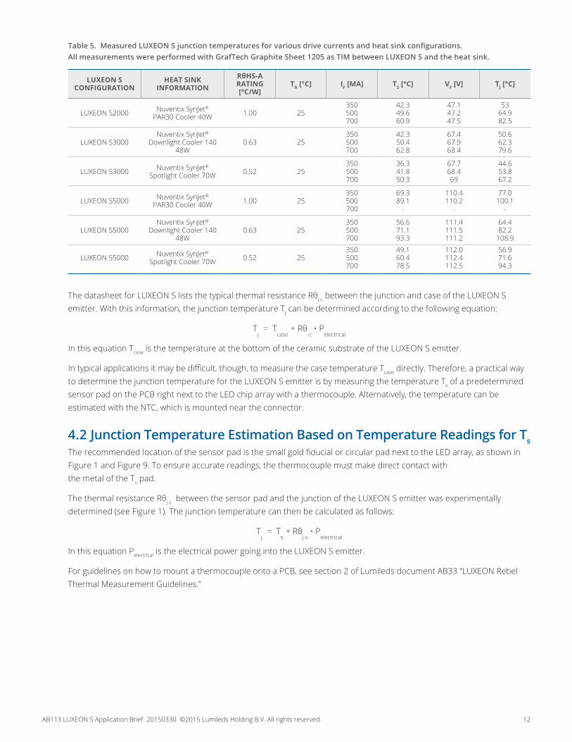
Table 5. Measured LUXEON S junction temperatures for various drive currents and heat sink configurations. All measurements were performed with GrafTech Graphite Sheet 1205 as TIM between LUXEON S and the heat sink.
LUXEON S CONFIGURATION
HEAT SINK INFORMATION
RθHS-A RATING [°C/W]
TA [°C] IF [MA] TS [°C] VF [V] TJ [°C]
LUXEON S2000 Nuventix SynJet® PAR30 Cooler 40W 1.00 25
350 500 700
42.3 49.6 60.9
47.1 47.2 47.5
53 64.9 82.5
LUXEON S3000Nuventix SynJet®
Downlight Cooler 140 48W
0.63 25350 500 700
42.3 50.4 62.8
67.4 67.9 68.4
50.6 62.3 79.6
LUXEON S3000 Nuventix SynJet® Spotlight Cooler 70W 0.52 25
350 500 700
36.3 41.8 50.3
67.7 68.4 69
44.6 53.8 67.2
LUXEON S5000 Nuventix SynJet® PAR30 Cooler 40W 1.00 25
350 500 700
69.3 89.1
-
110.4 110.2
-
77.0 100.1
-
LUXEON S5000Nuventix SynJet®
Downlight Cooler 140 48W
0.63 25350 500 700
56.6 71.1 93.3
111.4 111.5 111.2
64.4 82.2
108.9
LUXEON S5000 Nuventix SynJet® Spotlight Cooler 70W 0.52 25
350 500 700
49.1 60.4 78.5
112.0 112.4 112.5
56.9 71.6 94.3
The datasheet for LUXEON S lists the typical thermal resistance Rθj-c between the junction and case of the LUXEON S emitter. With this information, the junction temperature Tj can be determined according to the following equation:
Tj = T
case + Rθ-c • P
electrical
In this equation Tcase is the temperature at the bottom of the ceramic substrate of the LUXEON S emitter.
In typical applications it may be difficult, though, to measure the case temperature Tcase directly. Therefore, a practical way to determine the junction temperature for the LUXEON S emitter is by measuring the temperature Ts of a predetermined sensor pad on the PCB right next to the LED chip array with a thermocouple. Alternatively, the temperature can be estimated with the NTC, which is mounted near the connector.
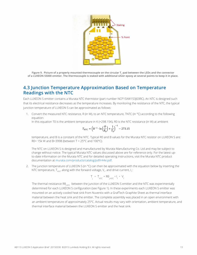
4.2 Junction Temperature Estimation Based on Temperature Readings for TsThe recommended location of the sensor pad is the small gold fiducial or circular pad next to the LED array, as shown in Figure 1 and Figure 9. To ensure accurate readings, the thermocouple must make direct contact with the metal of the Ts pad.
The thermal resistance Rθj-s between the sensor pad and the junction of the LUXEON S emitter was experimentally determined (see Figure 1). The junction temperature can then be calculated as follows:
Tj = T
s + Rθj-s
• Pelectrical
In this equation Pelectrical is the electrical power going into the LUXEON S emitter.
For guidelines on how to mount a thermocouple onto a PCB, see section 2 of Lumileds document AB33 “LUXEON Rebel Thermal Measurement Guidelines.”
AB113 LUXEON S Application Brief 20150330 ©2015 Lumileds Holding B.V. All rights reserved. 13
Figure 9. Picture of a properly mounted thermocouple on the circular Ts pad between the LEDs and the connector of a LUXEON S5000 emitter. The thermocouple is staked with additional silver epoxy at several points to keep it in place.
4.3 Junction Temperature Approximation Based on Temperature Readings with the NTC Each LUXEON S emitter contains a Murata NTC thermistor (part number NCP15XW153J03RC). An NTC is designed such that its electrical resistance decreases as the temperature increases. By monitoring the resistance of the NTC, the typical junction temperature of LUXEON S can be approximated as follows:
1. Convert the measured NTC resistance, R (in W), to an NTC temperature, TNTC (in °C) according to the following equation: In this equation T0 is the ambient temperature in K (=298.15K), R0 is the NTC resistance (in W) at ambient
temperature, and B is a constant of the NTC. Typical R0 and B values for the Murata NTC resistor on LUXEON S are: R0= 15k W and B=3998 (between T = 25°C and 100°C). The NTC on LUXEON S is designed and manufactured by Murata Manufacturing Co. Ltd and may be subject to change without notice. The typical Murata NTC values discussed above are for reference only. For the latest up-to-date information on the Murata NTC and for detailed operating instructions, visit the Murata NTC product documentation at murata.com/products/catalog/pdf/r44e.pdf.
2. The junction temperature of LUXEON S (in °C) can then be approximated with the equation below by inserting the NTC temperature, TNTC, along with the forward voltage, Vf , and drive current, If :
Tj = T
NTC + Rθj-NTC
• If • V
f
The thermal resistance Rθj-NTC between the junction of the LUXEON S emitter and the NTC was experimentally determined for each LUXEON S configuration (see Figure 1). In these experiments each LUXEON S emitter was mounted on an actively cooled heat sink from Nuventix with a GrafTech Graphite Sheet as thermal interface material between the heat sink and the emitter. The complete assembly was placed in an open environment with an ambient temperature of approximately 25°C. Actual results may vary with orientation, ambient temperature, and thermal interface material between the LUXEON S emitter and the heat sink.
���� = �B�� ∙ ln � ���� +1���
��− 273.15
AB113 LUXEON S Application Brief 20150330 ©2015 Lumileds Holding B.V. All rights reserved. 14
5. Packaging Considerations — Chemical CompatibilityThe LUXEON S emitter contains a silicone overcoat to protect the LED chips. As with most silicones used in LED optics, care must be taken to prevent any incompatible chemicals from directly or indirectly reacting with the silicone.
The silicone overcoat in the LUXEON S emitter is gas permeable. Consequently, oxygen and volatile organic compound (VOC) gas molecules can diffuse into the silicone overcoat. VOCs may originate from adhesives, solder fluxes, conformal coating materials, potting materials and even some of the inks that are used to print the PCBs.
Some VOCs and chemicals react with silicone and produce discoloration and surface damage. Other VOCs do not chemically react with the silicone material directly but diffuse into the silicone and oxidize during the presence of heat or light. Regardless of the physical mechanism, both cases may affect the total LED light output. Since silicone permeability increases with temperature, more VOCs may diffuse into and/or evaporate out from the silicone.
Careful consideration must be given to whether LUXEON S emitters are enclosed in an “air tight” environment or not. In an “air tight” environment, some VOCs that were introduced during assembly may permeate and remain in the silicone overcoat. Under heat and “blue” light, the VOCs inside the silicone overcoat may partially oxidize and create a silicone discoloration, particularly on the surface of the LED where the flux energy is the highest. In an air rich or “open” air environment, VOCs have a chance to leave the area (driven by the normal air flow). Transferring the devices which were discolored in the enclosed environment back to “open” air may allow the oxidized VOCs to diffuse out of the silicone overcoat and may restore the original optical properties of the LED.
Determining suitable threshold limits for the presence of VOCs is very difficult since these limits depend on the type of enclosure used to house the LEDs and the operating temperatures. Also, some VOCs can photo-degrade over time.
Table 6 provides a list of commonly used chemicals that should be avoided as they may react with the silicone material. Note that Lumileds does not warrant that this list is exhaustive since it is impossible to determine all chemicals that may adversely affect LED performance.
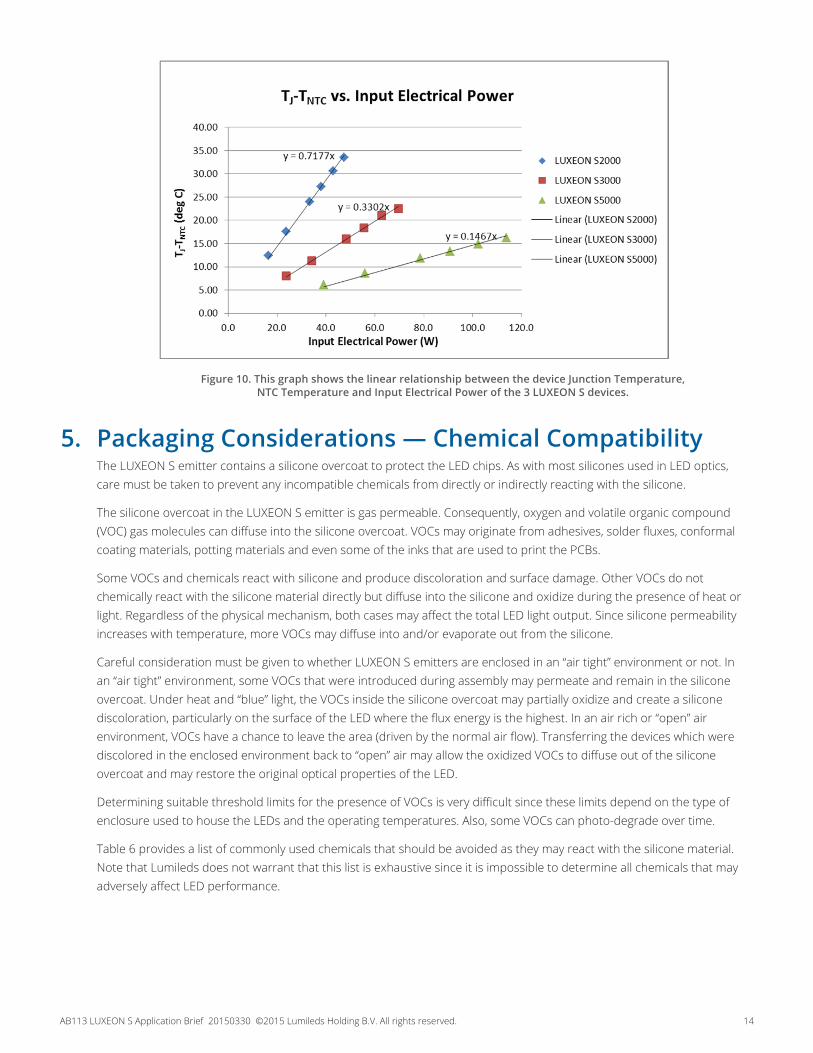
Figure 10. This graph shows the linear relationship between the device Junction Temperature,
NTC Temperature and Input Electrical Power of the 3 LUXEON S devices.
AB113 LUXEON S Application Brief 20150330 ©2015 Lumileds Holding B.V. All rights reserved. 15
RoHSCOMPLIANT
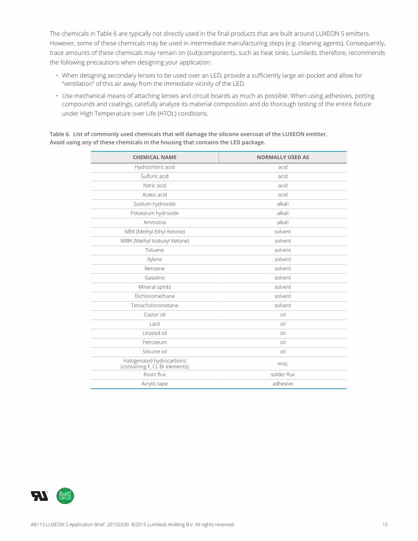
The chemicals in Table 6 are typically not directly used in the final products that are built around LUXEON S emitters. However, some of these chemicals may be used in intermediate manufacturing steps (e.g. cleaning agents). Consequently, trace amounts of these chemicals may remain on (sub)components, such as heat sinks. Lumileds, therefore, recommends the following precautions when designing your application:
• When designing secondary lenses to be used over an LED, provide a sufficiently large air-pocket and allow for “ventilation” of this air away from the immediate vicinity of the LED.
• Use mechanical means of attaching lenses and circuit boards as much as possible. When using adhesives, potting compounds and coatings, carefully analyze its material composition and do thorough testing of the entire fixture under High Temperature over Life (HTOL) conditions.
Table 6. List of commonly used chemicals that will damage the silicone overcoat of the LUXEON emitter. Avoid using any of these chemicals in the housing that contains the LED package.
CHEMICAL NAME NORMALLY USED AS
Hydrochloric acid acid
Sulfuric acid acid
Nitric acid acid
Acetic acid acid
Sodium hydroxide alkali
Potassium hydroxide alkali
Ammonia alkali
MEK (Methyl Ethyl Ketone) solvent
MIBK (Methyl Isobutyl Ketone) solvent
Toluene solvent
Xylene solvent
Benzene solvent
Gasoline solvent
Mineral spirits solvent
Dichloromethane solvent
Tetracholorometane solvent
Castor oil oil
Lard oil
Linseed oil oil
Petroleum oil
Silicone oil oil
Halogenated hydrocarbons (containing F, Cl, Br elements) misc
Rosin flux solder flux
Acrylic tape adhesive

©2015 Lumileds Holding B.V. All rights reserved. LUXEON is a registered trademark of the Lumileds Holding B.V. in the United States and other countries.
lumileds.com
Neither Lumileds Holding B.V. nor its affiliates shall be liable for any kind of loss of data or any other damages, direct, indirect or consequential, resulting from the use of the provided information and data. Although Lumileds Holding B.V. and/or its affiliates have attempted to provide the most accurate information and data, the materials and services information and data are provided “as is,” and neither Lumileds Holding B.V. nor its affiliates warrants or guarantees the contents and correctness of the provided information and data. Lumileds Holding B.V. and its affiliates reserve the right to make changes without notice. You as user agree to this disclaimer and user agreement with the download or use of the provided materials, information and data.
AB113 LUXEON S Application Brief 20150330
About LumiledsLumileds is the light engine leader, delivering innovation, quality and reliability.
For 100 years, Lumileds commitment to innovation has helped customers pioneer breakthrough products in the automotive, consumer and illumination markets.
Lumileds is shaping the future of light with our LEDs and automotive lamps, and helping our customers illuminate how people see the world around them.
To learn more about our portfolio of light engines, visit www.lumileds.com.