Embed Size (px)
Citation preview
LX3V-4PG
User manual
Website: http://www.we-con.com.cn/en
Technical Support: [email protected]
Skype: fcwkkj
Phone: 86-591-87868869
QQ: 1043098682
Technical forum: http://wecon.freeforums.net/
LX3V-4PG
1 WECON Technology Co., Ltd.
1. Introduction
The LX3V-4PG is pulse generator unit which has four channels. Each channel can control positioning
of an axis independently. It works by sending specified quantity of pulses (200 kHz maximum) to
Server controller or step motors.
The LX3V-4PG is an extension module of LX3V series PLC, which transfers data with the PLC using
the FROM/TO instructions.
There are two versions for LX3V-4PG, one is LX3V-4PGA (Advanced), and the other is LX3V-4PGB
(Basic). Please get more detail from [BFM description]
Warnings:
Make sure power is Cut off before installation/disassembly of the unit or connection of wires onto
the unit, to prevent electric shock or product damage.
2. Dimensions
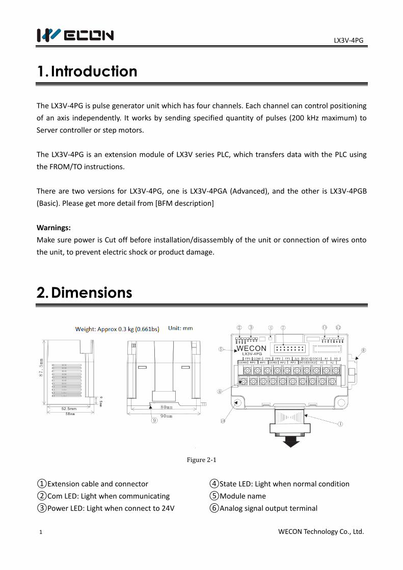
Figure 2-1
①Extension cable and connector
②Com LED: Light when communicating
③Power LED: Light when connect to 24V
④State LED: Light when normal condition
⑤Module name
⑥Analog signal output terminal

LX3V-4PG
2 WECON Technology Co., Ltd.
⑦Extension module interface
⑧DIN rail mounting slot
⑨DIN rail hook
⑩Mounting holes (φ4.5)
2.1 Crimp terminations
2.2 Terminals Definition
Terminal Instruction Terminal Instruction Terminal Instruction
COM0 Common terminal
for channel 1
FP2 Channel 3 outputs
pulses
S/S Common terminal
for X and DOG, it
supports NPN/PNP
type. FP0 Channel 1 outputs
pulses
RP2 Channel 3 outputs
direction
RP0 Channel 1 outputs
direction
FP3 Channel 4 outputs
pulses
DOG 3 Home position
return: Channel 4
near point signal
input
COM1 Common terminal
for channel 2
RP3 Channel 4 outputs
direction
X 0 Channel 1
interrupt signal
input
FP1 Channel 2 outputs
pulses
DOG 0 Home position
return: Channel 1
near point signal
input
X 1 Channel 2
interrupt signal
input
RP1 Channel 2 outputs
direction
DOG 1 Home position
return: Channel 2
near point signal
input
X 2 Channel 3
interrupt signal
input
COM 2 Common terminal
for channel 3 and 4
DOG 2 Home position
return: Channel 3
near point signal
input
X 3 Channel 4
interrupt signal
input
Please use crimp terminals as indicated on the graph.
The tightening torque should be applied 5 to 8 Kg.cm.
Other terminals should be empty but only wiring
terminals mention in this manual.
LX3V-4PG
2 WECON Technology Co., Ltd.
3. Input and output Specification
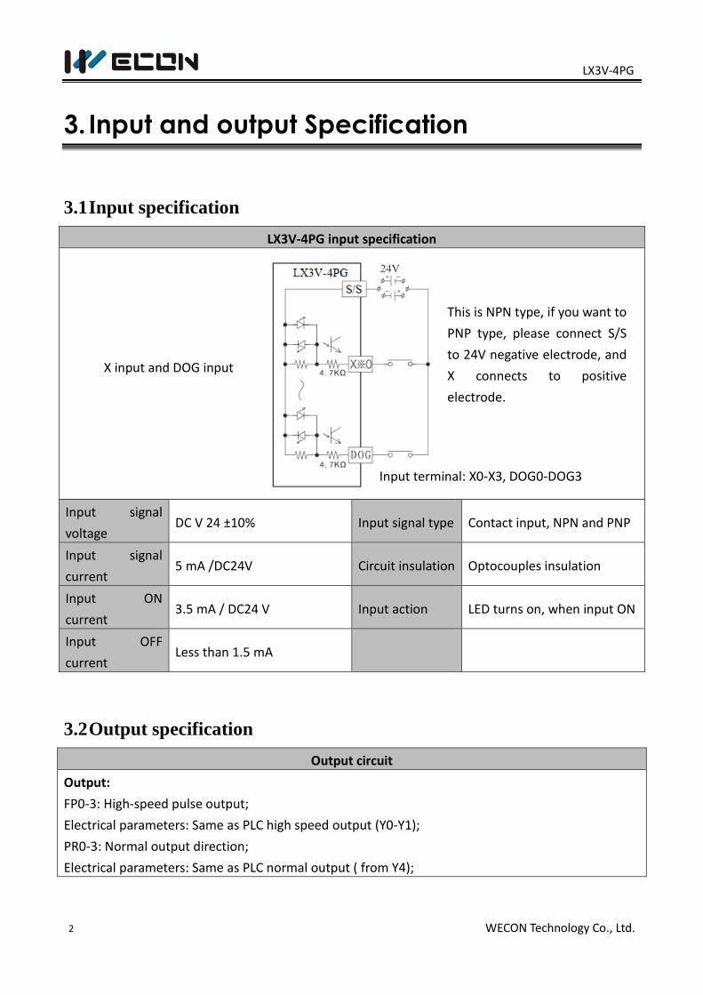
3.1 Input specification
LX3V-4PG input specification
Input signal
voltage DC V 24 ±10% Input signal type Contact input, NPN and PNP
Input signal
current 5 mA /DC24V Circuit insulation Optocouples insulation
Input ON
current 3.5 mA / DC24 V Input action LED turns on, when input ON
Input OFF
current Less than 1.5 mA
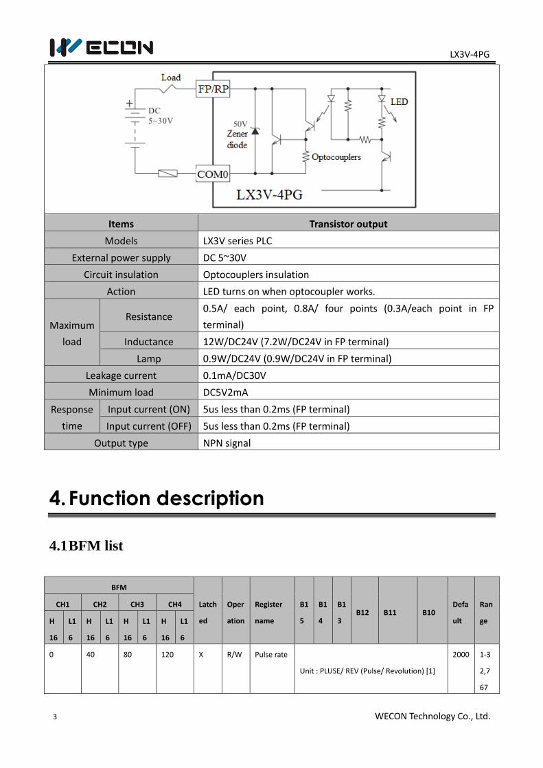
3.2 Output specification
Output circuit
Output:
FP0-3: High-speed pulse output;
Electrical parameters: Same as PLC high speed output (Y0-Y1);
PR0-3: Normal output direction;
Electrical parameters: Same as PLC normal output ( from Y4);
X input and DOG input
Input terminal: X0-X3, DOG0-DOG3
This is NPN type, if you want to
PNP type, please connect S/S
to 24V negative electrode, and
X connects to positive
electrode.
LX3V-4PG
3 WECON Technology Co., Ltd.
Items Transistor output
Models LX3V series PLC
External power supply DC 5~30V
Circuit insulation Optocouplers insulation
Action LED turns on when optocoupler works.
Maximum
load
Resistance 0.5A/ each point, 0.8A/ four points (0.3A/each point in FP
terminal)
Inductance 12W/DC24V (7.2W/DC24V in FP terminal)
Lamp 0.9W/DC24V (0.9W/DC24V in FP terminal)
Leakage current 0.1mA/DC30V
Minimum load DC5V2mA
Response
time
Input current (ON) 5us less than 0.2ms (FP terminal)
Input current (OFF) 5us less than 0.2ms (FP terminal)
Output type NPN signal
4. Function description
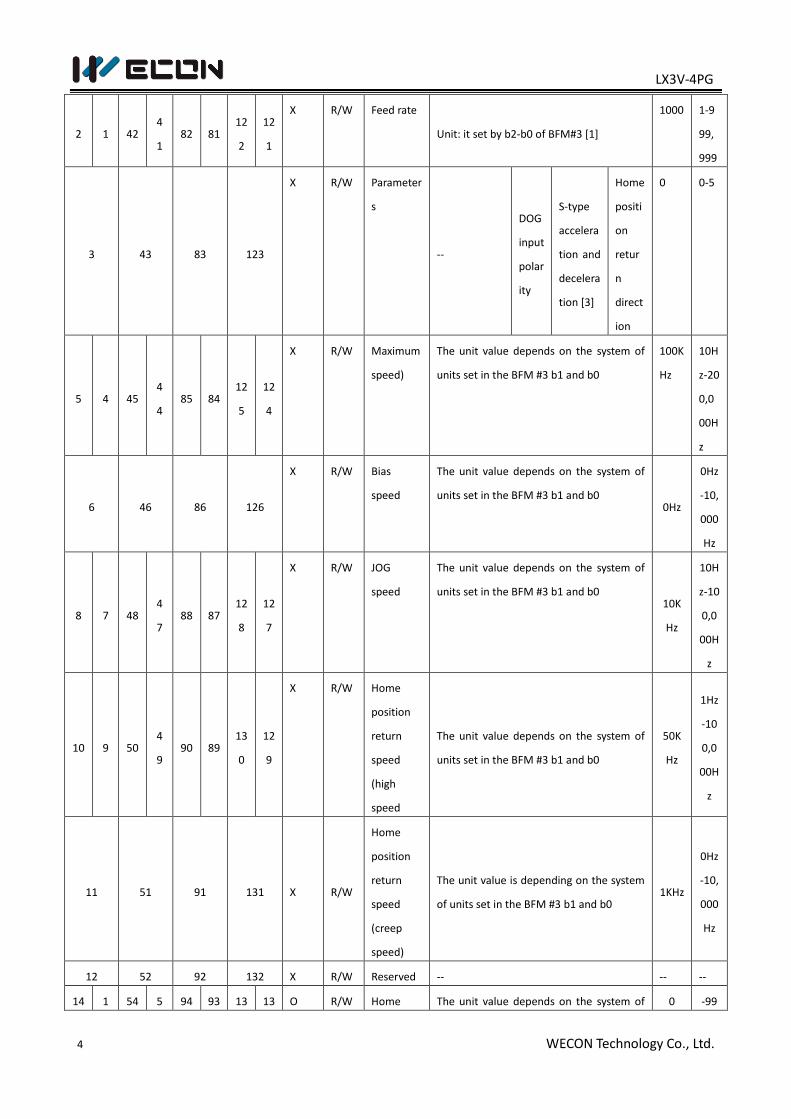
4.1 BFM list
BFM
Latch
ed
Oper
ation
Register
name
B1
5
B1
4
B1
3 B12 B11 B10
Defa
ult
Ran
ge
CH1 CH2 CH3 CH4
H
16
L1
6
H
16
L1
6
H
16
L1
6
H
16
L1
6
0 40 80 120 X R/W Pulse rate
Unit : PLUSE/ REV (Pulse/ Revolution) [1]
2000 1-3
2,7
67
LX3V-4PG
4 WECON Technology Co., Ltd.
2 1 42 4
1 82 81
12
2
12
1
X R/W Feed rate
Unit: it set by b2-b0 of BFM#3 [1]
1000 1-9
99,
999
3 43 83 123
X R/W Parameter
s
--
DOG
input
polar
ity
S-type
accelera
tion and
decelera
tion [3]
Home
positi
on
retur
n
direct
ion
0 0-5
5 4 45 4
4 85 84
12
5
12
4
X R/W Maximum
speed)
The unit value depends on the system of
units set in the BFM #3 b1 and b0
100K
Hz
10H
z-20
0,0
00H
z
6 46 86 126
X R/W Bias
speed
The unit value depends on the system of
units set in the BFM #3 b1 and b0 0Hz
0Hz
-10,
000
Hz
8 7 48 4
7 88 87
12
8
12
7
X R/W JOG
speed
The unit value depends on the system of
units set in the BFM #3 b1 and b0 10K
Hz
10H
z-10
0,0
00H
z
10 9 50 4
9 90 89
13
0
12
9
X R/W Home
position
return
speed
(high
speed
The unit value depends on the system of
units set in the BFM #3 b1 and b0
50K
Hz
1Hz
-10
0,0
00H
z
11 51 91 131 X R/W
Home
position
return
speed
(creep
speed)
The unit value is depending on the system
of units set in the BFM #3 b1 and b0 1KHz
0Hz
-10,
000
Hz
12 52 92 132 X R/W Reserved -- -- --
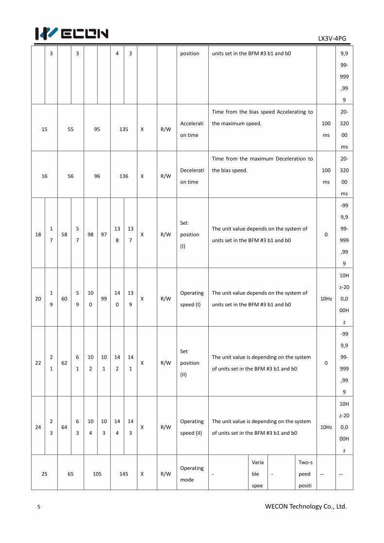
14 1 54 5 94 93 13 13 O R/W Home The unit value depends on the system of 0 -99
LX3V-4PG
5 WECON Technology Co., Ltd.
3 3 4 3 position units set in the BFM #3 b1 and b0 9,9
99-
999
,99
9
15 55 95 135 X R/W Accelerati
on time
Time from the bias speed Accelerating to
the maximum speed. 100
ms
20-
320
00
ms
16 56 96 136 X R/W Decelerati
on time
Time from the maximum Deceleration to
the bias speed. 100
ms
20-
320
00
ms
18 1
7 58
5
7 98 97
13
8
13
7 X R/W
Set
position
(I)
The unit value depends on the system of
units set in the BFM #3 b1 and b0 0
-99
9,9
99-
999
,99
9
20 1
9 60
5
9
10
0 99
14
0
13
9 X R/W
Operating
speed (I)
The unit value depends on the system of
units set in the BFM #3 b1 and b0 10Hz
10H
z-20
0,0
00H
z
22 2
1 62
6
1
10
2
10
1
14
2
14
1 X R/W
Set
position
(II)
The unit value is depending on the system
of units set in the BFM #3 b1 and b0 0
-99
9,9
99-
999
,99
9
24 2
3 64
6
3
10
4
10
3
14
4
14
3 X R/W
Operating
speed (II)
The unit value is depending on the system
of units set in the BFM #3 b1 and b0 10Hz
10H
z-20
0,0
00H
z
25 65 105 145 X R/W Operating
mode -
Varia
ble
spee
-
Two-s
peed
positi
-- --
LX3V-4PG
6 WECON Technology Co., Ltd.
d
oper
ation
start
on
start
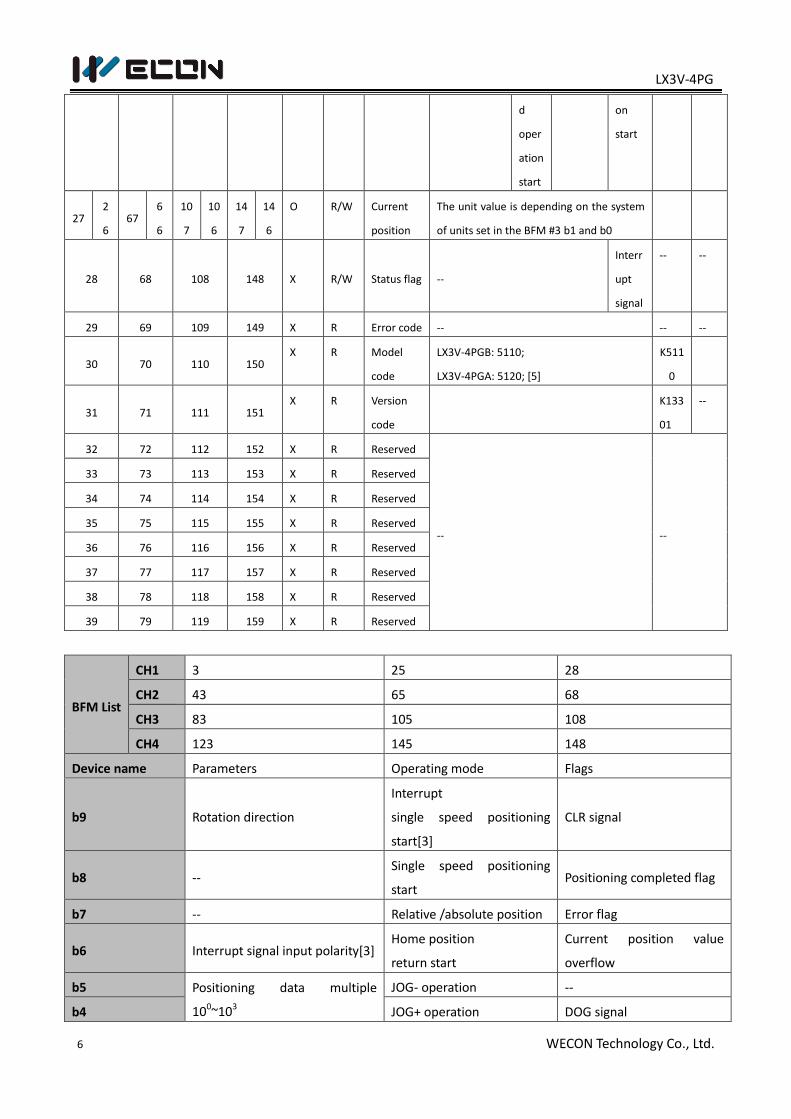
27 2
6 67
6
6
10
7
10
6
14
7
14
6
O R/W Current
position
The unit value is depending on the system
of units set in the BFM #3 b1 and b0
28 68 108 148 X R/W Status flag --
Interr
upt
signal
-- --
29 69 109 149 X R Error code -- -- --
30 70 110 150 X R Model
code
LX3V-4PGB: 5110;
LX3V-4PGA: 5120; [5]
K511
0
31 71 111 151 X R Version
code
K133
01
--
32 72 112 152 X R Reserved
-- --
33 73 113 153 X R Reserved
34 74 114 154 X R Reserved
35 75 115 155 X R Reserved
36 76 116 156 X R Reserved
37 77 117 157 X R Reserved
38 78 118 158 X R Reserved
39 79 119 159 X R Reserved
BFM List
CH1 3 25 28
CH2 43 65 68
CH3 83 105 108
CH4 123 145 148
Device name Parameters Operating mode Flags
b9 Rotation direction
Interrupt
single speed positioning
start[3]
CLR signal
b8 -- Single speed positioning
start Positioning completed flag
b7 -- Relative /absolute position Error flag
b6 Interrupt signal input polarity[3] Home position
return start
Current position value
overflow
b5 Positioning data multiple
100~103
JOG- operation --
b4 JOG+ operation DOG signal
LX3V-4PG
7 WECON Technology Co., Ltd.
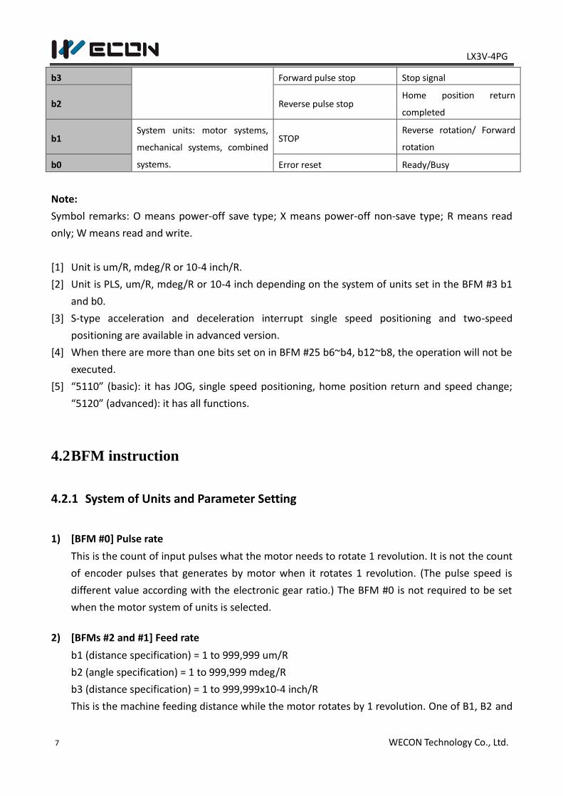
b3
Forward pulse stop Stop signal
b2 Reverse pulse stop Home position return
completed
b1 System units: motor systems,
mechanical systems, combined
systems.
STOP Reverse rotation/ Forward
rotation
b0 Error reset Ready/Busy
Note:
Symbol remarks: O means power-off save type; X means power-off non-save type; R means read
only; W means read and write.
[1] Unit is um/R, mdeg/R or 10-4 inch/R.
[2] Unit is PLS, um/R, mdeg/R or 10-4 inch depending on the system of units set in the BFM #3 b1
and b0.
[3] S-type acceleration and deceleration interrupt single speed positioning and two-speed
positioning are available in advanced version.
[4] When there are more than one bits set on in BFM #25 b6~b4, b12~b8, the operation will not be
executed.
[5] “5110” (basic): it has JOG, single speed positioning, home position return and speed change;
“5120” (advanced): it has all functions.
4.2 BFM instruction
4.2.1 System of Units and Parameter Setting
1) [BFM #0] Pulse rate
This is the count of input pulses what the motor needs to rotate 1 revolution. It is not the count
of encoder pulses that generates by motor when it rotates 1 revolution. (The pulse speed is
different value according with the electronic gear ratio.) The BFM #0 is not required to be set
when the motor system of units is selected.
2) [BFMs #2 and #1] Feed rate
b1 (distance specification) = 1 to 999,999 um/R
b2 (angle specification) = 1 to 999,999 mdeg/R
b3 (distance specification) = 1 to 999,999x10-4 inch/R
This is the machine feeding distance while the motor rotates by 1 revolution. One of B1, B2 and
LX3V-4PG
8 WECON Technology Co., Ltd.
B3 could be selected, the unit could be um/R, mdeg/R and 10-4 inch/R. The BFMs #2 and #1 are
not required to be set when the motor system of units is selected.
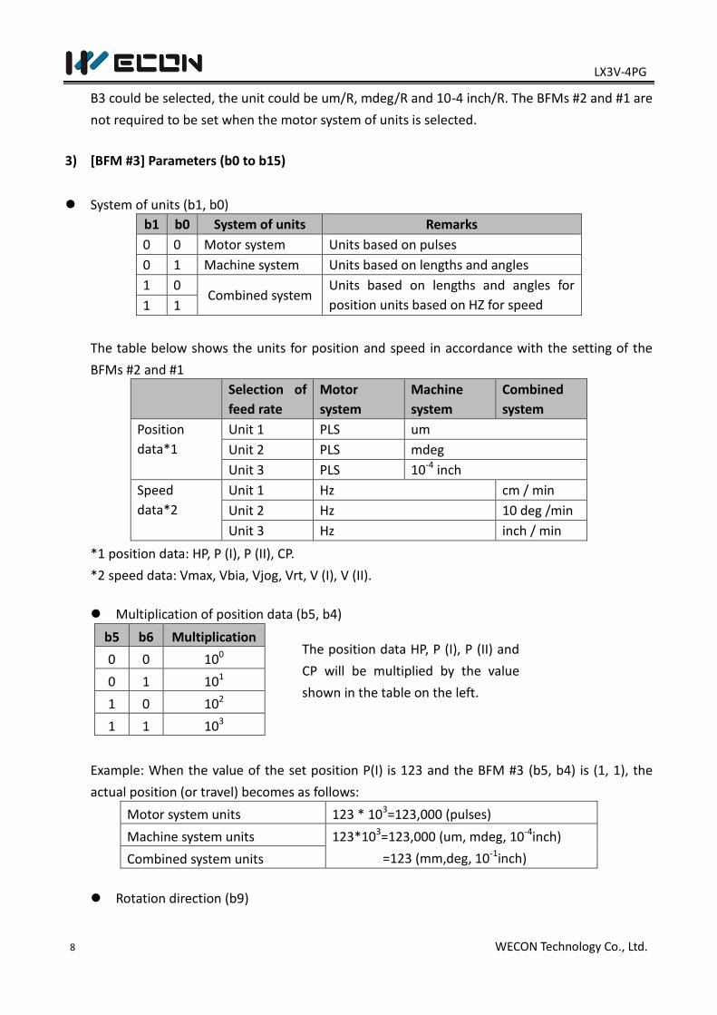
3) [BFM #3] Parameters (b0 to b15)
System of units (b1, b0)
b1 b0 System of units Remarks
0 0 Motor system Units based on pulses
0 1 Machine system Units based on lengths and angles
1 0 Combined system
Units based on lengths and angles for
position units based on HZ for speed 1 1
The table below shows the units for position and speed in accordance with the setting of the
BFMs #2 and #1
Selection of
feed rate
Motor
system
Machine
system
Combined
system
Position
data*1
Unit 1 PLS um
Unit 2 PLS mdeg
Unit 3 PLS 10-4 inch
Speed
data*2
Unit 1 Hz cm / min
Unit 2 Hz 10 deg /min
Unit 3 Hz inch / min
*1 position data: HP, P (I), P (II), CP.
*2 speed data: Vmax, Vbia, Vjog, Vrt, V (I), V (II).
Multiplication of position data (b5, b4)
b5 b6 Multiplication
0 0 100
0 1 101
1 0 102
1 1 103
Example: When the value of the set position P(I) is 123 and the BFM #3 (b5, b4) is (1, 1), the
actual position (or travel) becomes as follows:
Motor system units 123 * 103=123,000 (pulses)
Machine system units 123*103=123,000 (um, mdeg, 10-4inch)
=123 (mm,deg, 10-1inch) Combined system units
Rotation direction (b9)
The position data HP, P (I), P (II) and
CP will be multiplied by the value
shown in the table on the left.
LX3V-4PG
9 WECON Technology Co., Ltd.
When b9 = 0: The current position (CP) value increases with a forward pulse (FP).
When b9 = 1: The current position (CP) value decreases with a forward pulse (FP).
This bit is used for the initialized setting. The change of rotation direction is not active when the
positioning works.
The direction of home position return (b10)
When b10 = 0: The current position (CP) value decreases during return to the home position.
When b10 = 1: The current position (CP) value increases during return to the home position.
S-type acceleration and deceleration(b11)
When b11=0, the acceleration is constant during the process of accelerating and decelerating
for positioning, the curve of speed is trapezoidal.
When b11=1, the curve of speed is S-type during the process of accelerating and decelerating
for positioning.
DOG input polarity (b12)
When b12 = 0: The DOG (near point signal) is turned on when the workpiece is approaching the
home position.
When b12 = 1: The DOG (near point signal) is turned off when the workpiece is approaching the
home position.
4.2.2 Speed Data and Positioning Data
1) [BFMs #5 and #4] Maximum speed Vmax
Motor system and combined system: 1 to 200,000 Hz
This is the setting of maximum speed. Make sure that the bias speed (BFM #6), the JOG speed
(BFMs #7 and #8), the speed of home position return (BFMs #9 and #10), the creep speed (BFM
#11), the operating speed (I) (BFMs #19 and #20) and the operating speed (II) (BFMs #23 and
#24) should be equal to or less than the maximum speed. The degree of
acceleration/deceleration is determined by this maximum speed, the bias speed (BFM #6), the
acceleration time (BFM #15) and the deceleration time (BFM#16).
2) [BFM #6] Bias speed Vbia
The range is 0 to 10,000Hz
This is the bias speed for start. When the LX3V-4PG and the stepper motor works together, it is
necessary to set a value while considering the resonance area and the self-start frequency of
the stepper motor
LX3V-4PG
10 WECON Technology Co., Ltd.
3) [BFMs #8 and #7] JOG speed VJOG
The range is 1 to 100,000Hz
This is the speed for manual forward/reverse (JOG+/JOG-). It should be between the bias speed
Vbia and the maximum speed Vmax
4) [BFMs #10 and #9] The speed of home position return (high speed) VRT
The range is 10 to 100,000Hz
This is the speed (high speed) for returning to home position. It should be between the bias
speed Vbia and the maximum speed Vmax.
5) [BFM #11] The speed of home position return (creep) VCR
This is the speed (extremely slow speed) after the ear point signal (DOG) for returning to home
position. It is instantaneous velocity before stopping at home position. Slower speed could get
high precision of home positioning.
6) [BFMs#14 and #13] Home position HP
Motor system: 0 to ±999,999 PLS. Machine system and combined system: 0 to ±999,999
This is the position of home position return, when return actions completes, the value is
written to the current position (BFMs #26 and #27).
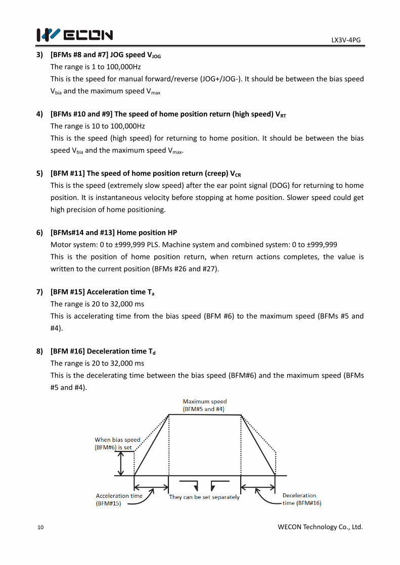
7) [BFM #15] Acceleration time Ta
The range is 20 to 32,000 ms
This is accelerating time from the bias speed (BFM #6) to the maximum speed (BFMs #5 and
#4).
8) [BFM #16] Deceleration time Td
The range is 20 to 32,000 ms
This is the decelerating time between the bias speed (BFM#6) and the maximum speed (BFMs
#5 and #4).
LX3V-4PG
11 WECON Technology Co., Ltd.
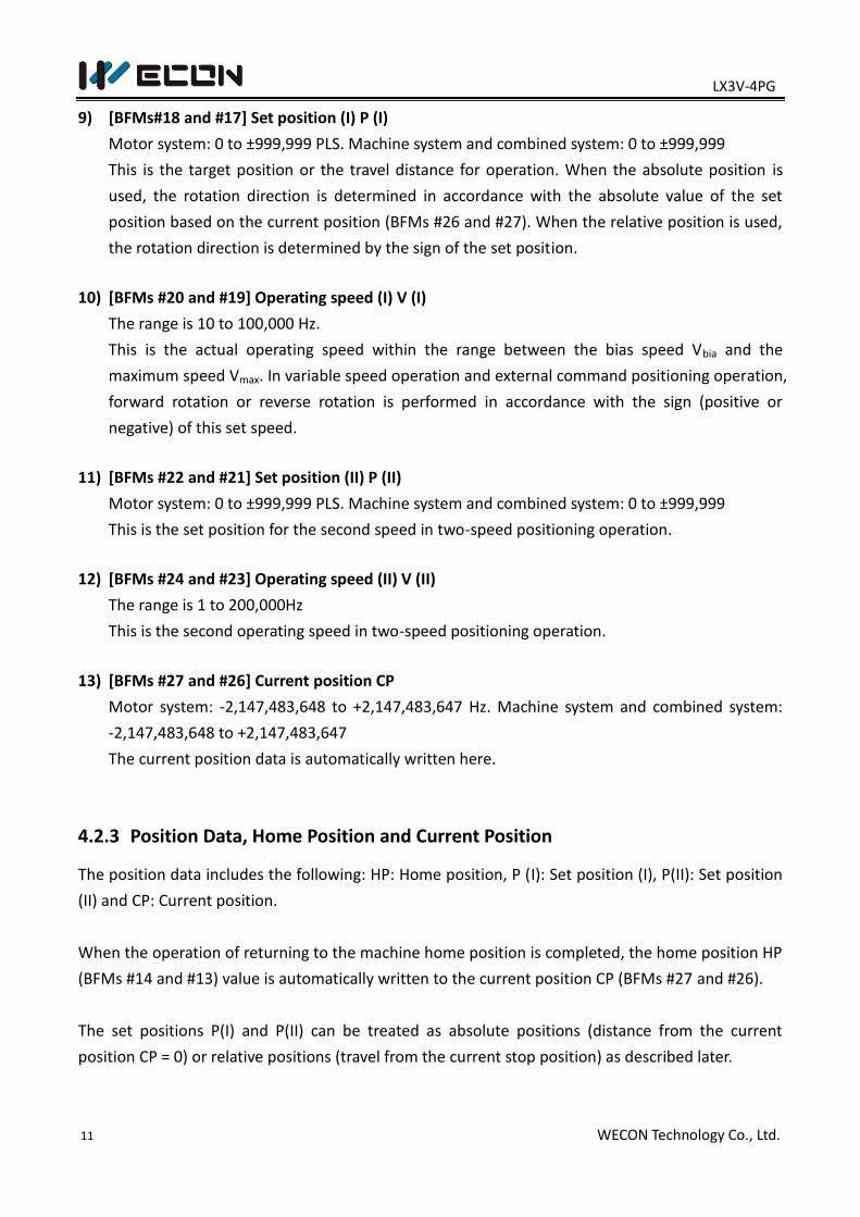
9) [BFMs#18 and #17] Set position (I) P (I)
Motor system: 0 to ±999,999 PLS. Machine system and combined system: 0 to ±999,999
This is the target position or the travel distance for operation. When the absolute position is
used, the rotation direction is determined in accordance with the absolute value of the set
position based on the current position (BFMs #26 and #27). When the relative position is used,
the rotation direction is determined by the sign of the set position.
10) [BFMs #20 and #19] Operating speed (I) V (I)
The range is 10 to 100,000 Hz.
This is the actual operating speed within the range between the bias speed Vbia and the
maximum speed Vmax. In variable speed operation and external command positioning operation,
forward rotation or reverse rotation is performed in accordance with the sign (positive or
negative) of this set speed.
11) [BFMs #22 and #21] Set position (II) P (II)
Motor system: 0 to ±999,999 PLS. Machine system and combined system: 0 to ±999,999
This is the set position for the second speed in two-speed positioning operation.
12) [BFMs #24 and #23] Operating speed (II) V (II)
The range is 1 to 200,000Hz
This is the second operating speed in two-speed positioning operation.
13) [BFMs #27 and #26] Current position CP
Motor system: -2,147,483,648 to +2,147,483,647 Hz. Machine system and combined system:
-2,147,483,648 to +2,147,483,647
The current position data is automatically written here.
4.2.3 Position Data, Home Position and Current Position
The position data includes the following: HP: Home position, P (I): Set position (I), P(II): Set position
(II) and CP: Current position.
When the operation of returning to the machine home position is completed, the home position HP
(BFMs #14 and #13) value is automatically written to the current position CP (BFMs #27 and #26).
The set positions P(I) and P(II) can be treated as absolute positions (distance from the current
position CP = 0) or relative positions (travel from the current stop position) as described later.
LX3V-4PG
12 WECON Technology Co., Ltd.
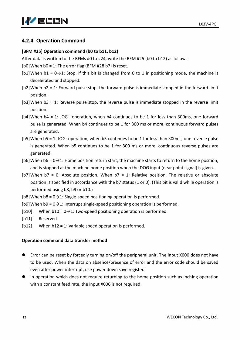
4.2.4 Operation Command
[BFM #25] Operation command (b0 to b11, b12)
After data is written to the BFMs #0 to #24, write the BFM #25 (b0 to b12) as follows.
[b0] When b0 = 1: The error flag (BFM #28 b7) is reset.
[b1] When b1 = 0→1: Stop, if this bit is changed from 0 to 1 in positioning mode, the machine is
decelerated and stopped.
[b2] When b2 = 1: Forward pulse stop, the forward pulse is immediate stopped in the forward limit
position.
[b3] When b3 = 1: Reverse pulse stop, the reverse pulse is immediate stopped in the reverse limit
position.
[b4] When b4 = 1: JOG+ operation, when b4 continues to be 1 for less than 300ms, one forward
pulse is generated. When b4 continues to be 1 for 300 ms or more, continuous forward pulses
are generated.
[b5] When b5 = 1: JOG- operation, when b5 continues to be 1 for less than 300ms, one reverse pulse
is generated. When b5 continues to be 1 for 300 ms or more, continuous reverse pulses are
generated.
[b6] When b6 = 0→1: Home position return start, the machine starts to return to the home position,
and is stopped at the machine home position when the DOG input (near point signal) is given.
[b7] When b7 = 0: Absolute position. When b7 = 1: Relative position. The relative or absolute
position is specified in accordance with the b7 status (1 or 0). (This bit is valid while operation is
performed using b8, b9 or b10.)
[b8] When b8 = 0→1: Single-speed positioning operation is performed.
[b9] When b9 = 0→1: Interrupt single-speed positioning operation is performed.
[b10] When b10 = 0→1: Two-speed positioning operation is performed.
[b11] Reserved
[b12] When b12 = 1: Variable speed operation is performed.
Operation command data transfer method
Error can be reset by forcedly turning on/off the peripheral unit. The input X000 does not have
to be used. When the data on absence/presence of error and the error code should be saved
even after power interrupt, use power down save register.
In operation which does not require returning to the home position such as inching operation
with a constant feed rate, the input X006 is not required.
LX3V-4PG
13 WECON Technology Co., Ltd.
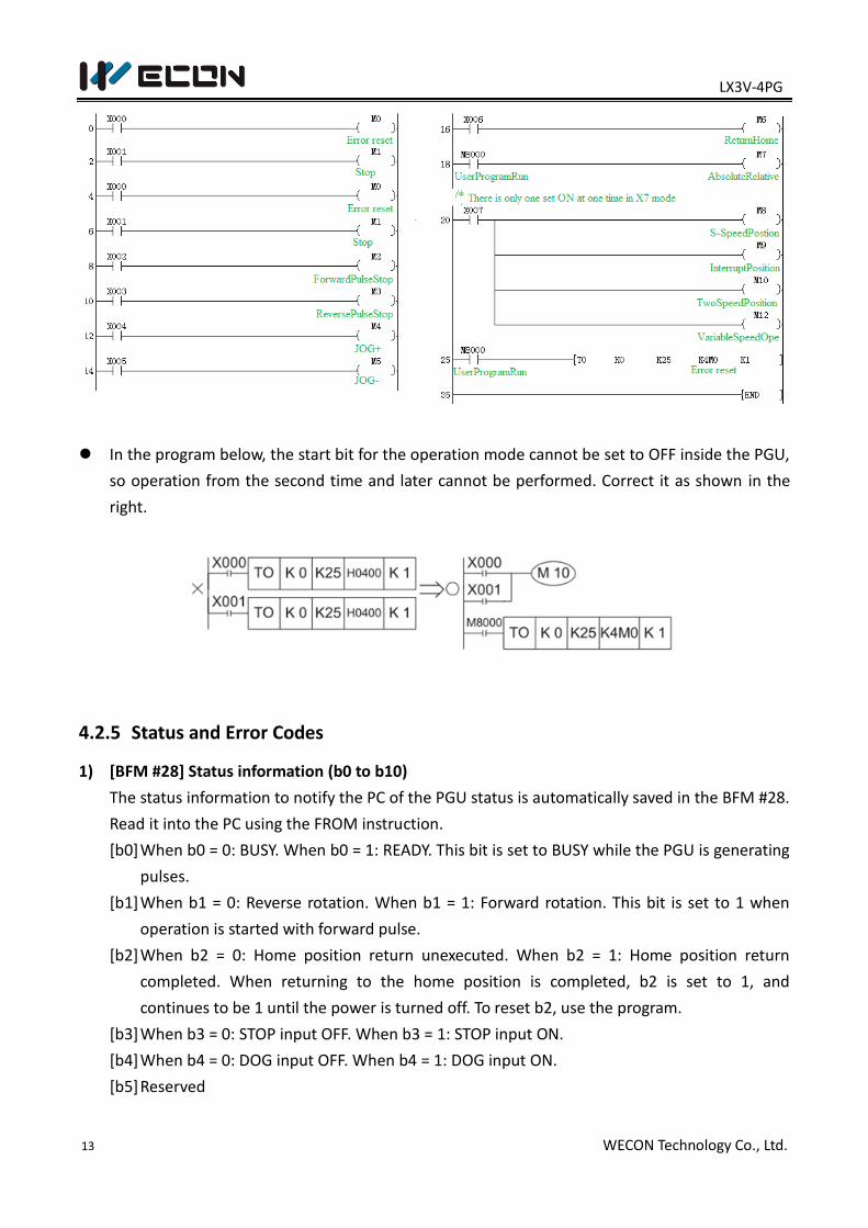
In the program below, the start bit for the operation mode cannot be set to OFF inside the PGU,
so operation from the second time and later cannot be performed. Correct it as shown in the
right.
4.2.5 Status and Error Codes
1) [BFM #28] Status information (b0 to b10)
The status information to notify the PC of the PGU status is automatically saved in the BFM #28.
Read it into the PC using the FROM instruction.
[b0] When b0 = 0: BUSY. When b0 = 1: READY. This bit is set to BUSY while the PGU is generating
pulses.
[b1] When b1 = 0: Reverse rotation. When b1 = 1: Forward rotation. This bit is set to 1 when
operation is started with forward pulse.
[b2] When b2 = 0: Home position return unexecuted. When b2 = 1: Home position return
completed. When returning to the home position is completed, b2 is set to 1, and
continues to be 1 until the power is turned off. To reset b2, use the program.
[b3] When b3 = 0: STOP input OFF. When b3 = 1: STOP input ON.
[b4] When b4 = 0: DOG input OFF. When b4 = 1: DOG input ON.
[b5] Reserved
LX3V-4PG
14 WECON Technology Co., Ltd.
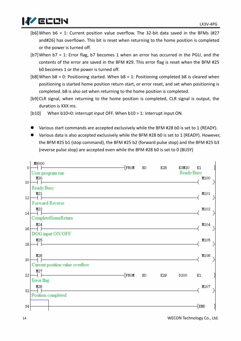
[b6] When b6 = 1: Current position value overflow. The 32-bit data saved in the BFMs (#27
and#26) has overflown. This bit is reset when returning to the home position is completed
or the power is turned off.
[b7] When b7 = 1: Error flag, b7 becomes 1 when an error has occurred in the PGU, and the
contents of the error are saved in the BFM #29. This error flag is reset when the BFM #25
b0 becomes 1 or the power is turned off.
[b8] When b8 = 0: Positioning started. When b8 = 1: Positioning completed b8 is cleared when
positioning is started home position return start, or error reset, and set when positioning is
completed. b8 is also set when returning to the home position is completed.
[b9] CLR signal, when returning to the home position is completed, CLR signal is output, the
duration is XXX ms.
[b10] When b10=0: interrupt input OFF. When b10 = 1: interrupt input ON.
Various start commands are accepted exclusively while the BFM #28 b0 is set to 1 (READY).
Various data is also accepted exclusively while the BFM #28 b0 is set to 1 (READY). However,
the BFM #25 b1 (stop command), the BFM #25 b2 (forward pulse stop) and the BFM #25 b3
(reverse pulse stop) are accepted even while the BFM #28 b0 is set to 0 (BUSY)
LX3V-4PG
15 WECON Technology Co., Ltd.
2) [BFM #29] Error code number
The following error codes Nos. are saved in the BFM#29. Read and check it when the BFM #28
b7 is set to 1 (Error present).
001: Large/small relationship is incorrect. (V max <Vbia or V RT < V CR);
002: Setting is not performed yet. (V (I), P (I), V (II) or P (II));
003: Setting range is incorrect;
00 indicates the corresponding BFM No. For example, “172" indicates that the BFMs #18 and
#17 are set to 0. “043" indicates that the BFMs #5 and #4 are set to a value outside the range.
When a speed command specifies a value equivalent to or more than V max or a value
equivalent to or less than Vbia, error does not occur. V max or Vbia is used for operation.
Though the ready status can be specified even while an error is present, the start command is
not accepted.
4.3 Function description
Seven operation modes are available in the PG in accordance with the start command type. The
data on speed and position should be transferred preliminarily from the PC to the buffer memories
(BFMs) of the PG.
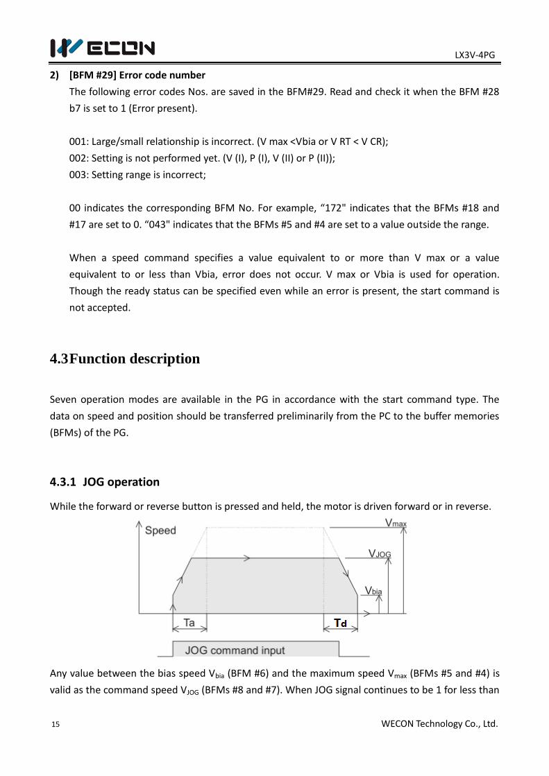
4.3.1 JOG operation
While the forward or reverse button is pressed and held, the motor is driven forward or in reverse.
Any value between the bias speed Vbia (BFM #6) and the maximum speed Vmax (BFMs #5 and #4) is
valid as the command speed VJOG (BFMs #8 and #7). When JOG signal continues to be 1 for less than
LX3V-4PG
16 WECON Technology Co., Ltd.
300ms, one reverse pulse is generated. When JOG signal continues to be 1 for 300 ms or more,
continuous reverse pulses are generated.
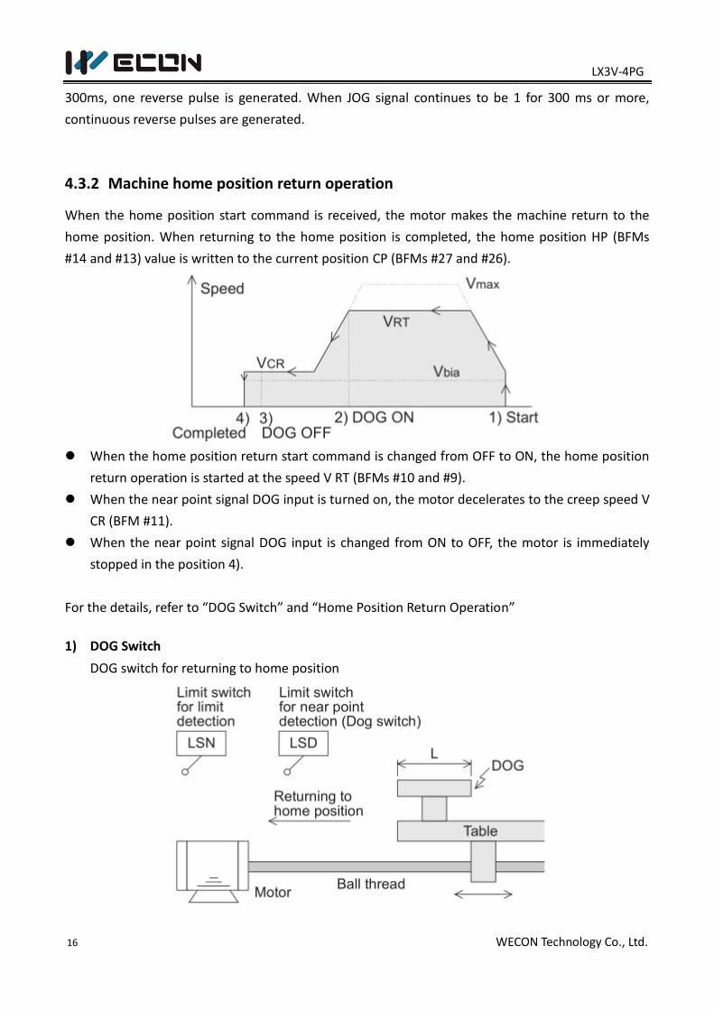
4.3.2 Machine home position return operation
When the home position start command is received, the motor makes the machine return to the
home position. When returning to the home position is completed, the home position HP (BFMs
#14 and #13) value is written to the current position CP (BFMs #27 and #26).
When the home position return start command is changed from OFF to ON, the home position
return operation is started at the speed V RT (BFMs #10 and #9).
When the near point signal DOG input is turned on, the motor decelerates to the creep speed V
CR (BFM #11).
When the near point signal DOG input is changed from ON to OFF, the motor is immediately
stopped in the position 4).
For the details, refer to “DOG Switch” and “Home Position Return Operation”
1) DOG Switch
DOG switch for returning to home position
LX3V-4PG
17 WECON Technology Co., Ltd.
A dog whose length is L is fixed to a table driven in the left and right direction by a servo motor
via a ball thread.
When the table moves in the home position return direction, the dog is in contact with the limit
switch (LSD) for near point detection, and the LSD is actuated.
The LSD is turned ON from OFF when the BFM #3 b12 is set to 0, and turned OFF from ON when
the BFM #3 b12 is set to 1.
The home position return direction is determined by the BFM #3 b9 (rotation direction) and
b10 (home position return direction).
The limit switch LSD is often referred to as dog switch. The actuation point of the dog switch is
rather dispersed.
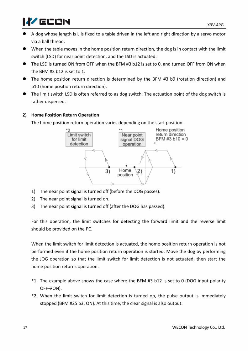
2) Home Position Return Operation
The home position return operation varies depending on the start position.
1) The near point signal is turned off (before the DOG passes).
2) The near point signal is turned on.
3) The near point signal is turned off (after the DOG has passed).
For this operation, the limit switches for detecting the forward limit and the reverse limit
should be provided on the PC.
When the limit switch for limit detection is actuated, the home position return operation is not
performed even if the home position return operation is started. Move the dog by performing
the JOG operation so that the limit switch for limit detection is not actuated, then start the
home position returns operation.
*1 The example above shows the case where the BFM #3 b12 is set to 0 (DOG input polarity
OFF→ON).
*2 When the limit switch for limit detection is turned on, the pulse output is immediately
stopped (BFM #25 b3: ON). At this time, the clear signal is also output.
LX3V-4PG
18 WECON Technology Co., Ltd.
When the stepper motor is used
When the stepper motor is used, rigid attention should be paid to the following items.
a) If the motor capacity is not sufficient compared with the load torque, the motor may stall. In
such a case, even if the specified quantity of pulses are supplied the motor, the expected drive
quantity may not be obtained.
b) Start and stop the motor slowly enough (by setting a long acceleration/deceleration time to the
BFM #15) so that the acceleration/ deceleration torque does not become excessive.
c) A resonance point is present in low speed operation. It is recommended to avoid this point. Set
the bias speed (BFM #6), and do not perform operation at a speed slower than that.
d) An external power supply may be required for signal communication with the drive amplifier.
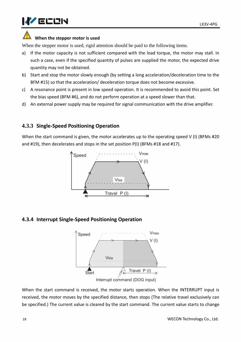
4.3.3 Single-Speed Positioning Operation
When the start command is given, the motor accelerates up to the operating speed V (I) (BFMs #20
and #19), then decelerates and stops in the set position P(I) (BFMs #18 and #17).
4.3.4 Interrupt Single-Speed Positioning Operation
When the start command is received, the motor starts operation. When the INTERRUPT input is
received, the motor moves by the specified distance, then stops (The relative travel exclusively can
be specified.) The current value is cleared by the start command. The current value starts to change
LX3V-4PG
19 WECON Technology Co., Ltd.
by the INTERRUPT input, and becomes equivalent to the set position when the operation is
completed.
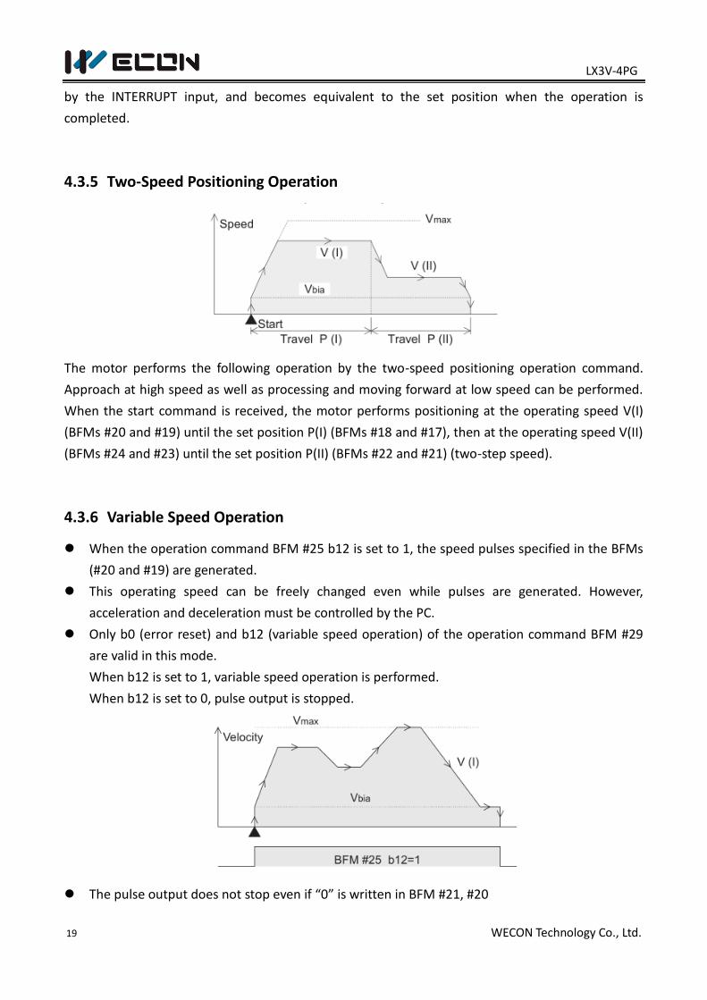
4.3.5 Two-Speed Positioning Operation
The motor performs the following operation by the two-speed positioning operation command.
Approach at high speed as well as processing and moving forward at low speed can be performed.
When the start command is received, the motor performs positioning at the operating speed V(I)
(BFMs #20 and #19) until the set position P(I) (BFMs #18 and #17), then at the operating speed V(II)
(BFMs #24 and #23) until the set position P(II) (BFMs #22 and #21) (two-step speed).
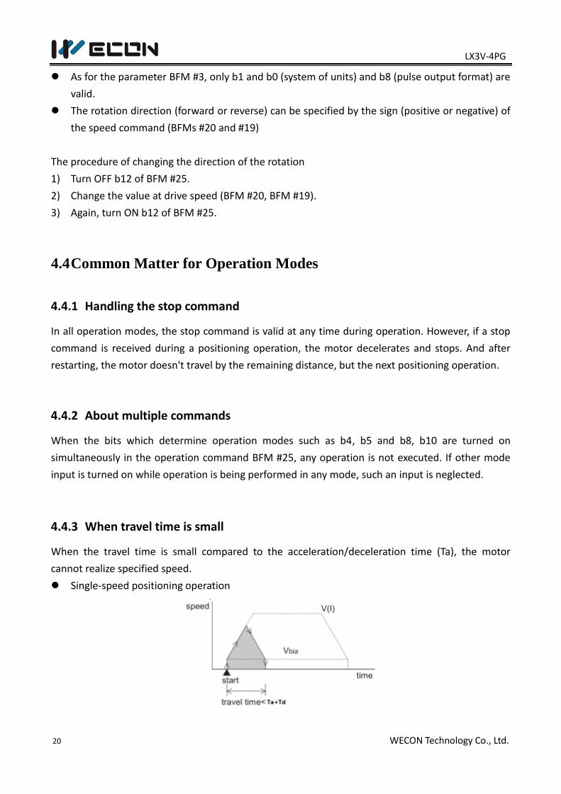
4.3.6 Variable Speed Operation
When the operation command BFM #25 b12 is set to 1, the speed pulses specified in the BFMs
(#20 and #19) are generated.
This operating speed can be freely changed even while pulses are generated. However,
acceleration and deceleration must be controlled by the PC.
Only b0 (error reset) and b12 (variable speed operation) of the operation command BFM #29
are valid in this mode.
When b12 is set to 1, variable speed operation is performed.
When b12 is set to 0, pulse output is stopped.
The pulse output does not stop even if “0” is written in BFM #21, #20
LX3V-4PG
20 WECON Technology Co., Ltd.
As for the parameter BFM #3, only b1 and b0 (system of units) and b8 (pulse output format) are
valid.
The rotation direction (forward or reverse) can be specified by the sign (positive or negative) of
the speed command (BFMs #20 and #19)
The procedure of changing the direction of the rotation
1) Turn OFF b12 of BFM #25.
2) Change the value at drive speed (BFM #20, BFM #19).
3) Again, turn ON b12 of BFM #25.
4.4 Common Matter for Operation Modes
4.4.1 Handling the stop command
In all operation modes, the stop command is valid at any time during operation. However, if a stop
command is received during a positioning operation, the motor decelerates and stops. And after
restarting, the motor doesn't travel by the remaining distance, but the next positioning operation.
4.4.2 About multiple commands
When the bits which determine operation modes such as b4, b5 and b8, b10 are turned on
simultaneously in the operation command BFM #25, any operation is not executed. If other mode
input is turned on while operation is being performed in any mode, such an input is neglected.
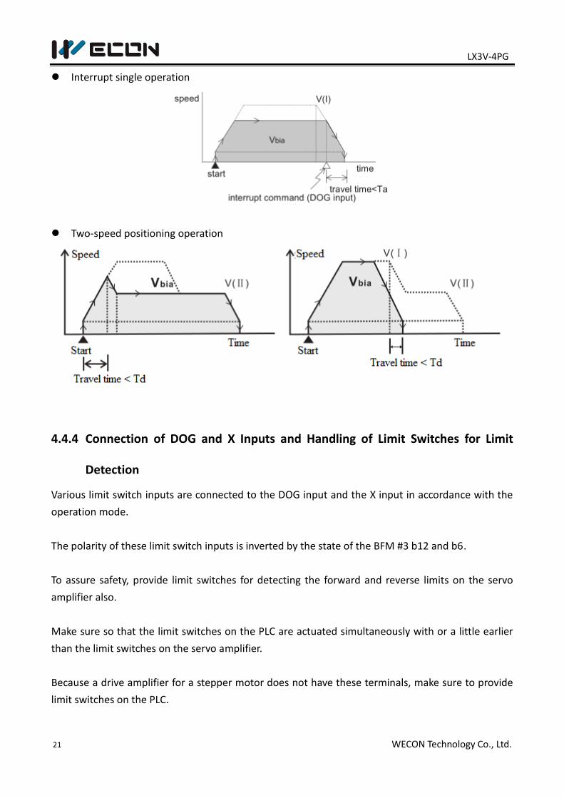
4.4.3 When travel time is small
When the travel time is small compared to the acceleration/deceleration time (Ta), the motor
cannot realize specified speed.
Single-speed positioning operation
LX3V-4PG
21 WECON Technology Co., Ltd.
Interrupt single operation
Two-speed positioning operation
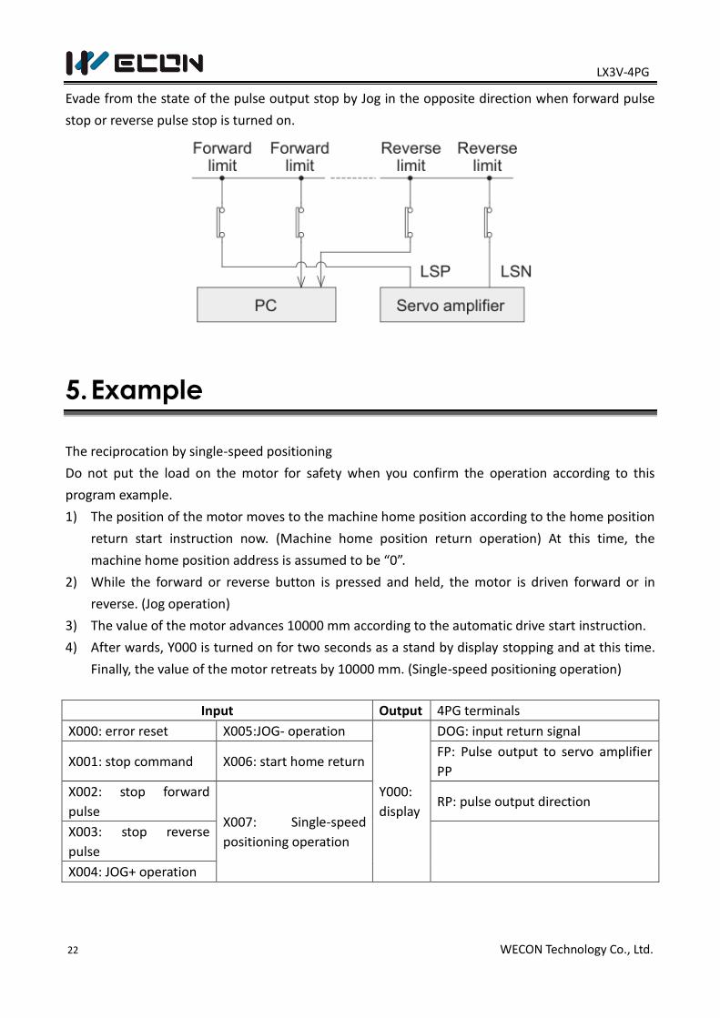
4.4.4 Connection of DOG and X Inputs and Handling of Limit Switches for Limit
Detection
Various limit switch inputs are connected to the DOG input and the X input in accordance with the
operation mode.
The polarity of these limit switch inputs is inverted by the state of the BFM #3 b12 and b6.
To assure safety, provide limit switches for detecting the forward and reverse limits on the servo
amplifier also.
Make sure so that the limit switches on the PLC are actuated simultaneously with or a little earlier
than the limit switches on the servo amplifier.
Because a drive amplifier for a stepper motor does not have these terminals, make sure to provide
limit switches on the PLC.
LX3V-4PG
22 WECON Technology Co., Ltd.
Evade from the state of the pulse output stop by Jog in the opposite direction when forward pulse
stop or reverse pulse stop is turned on.
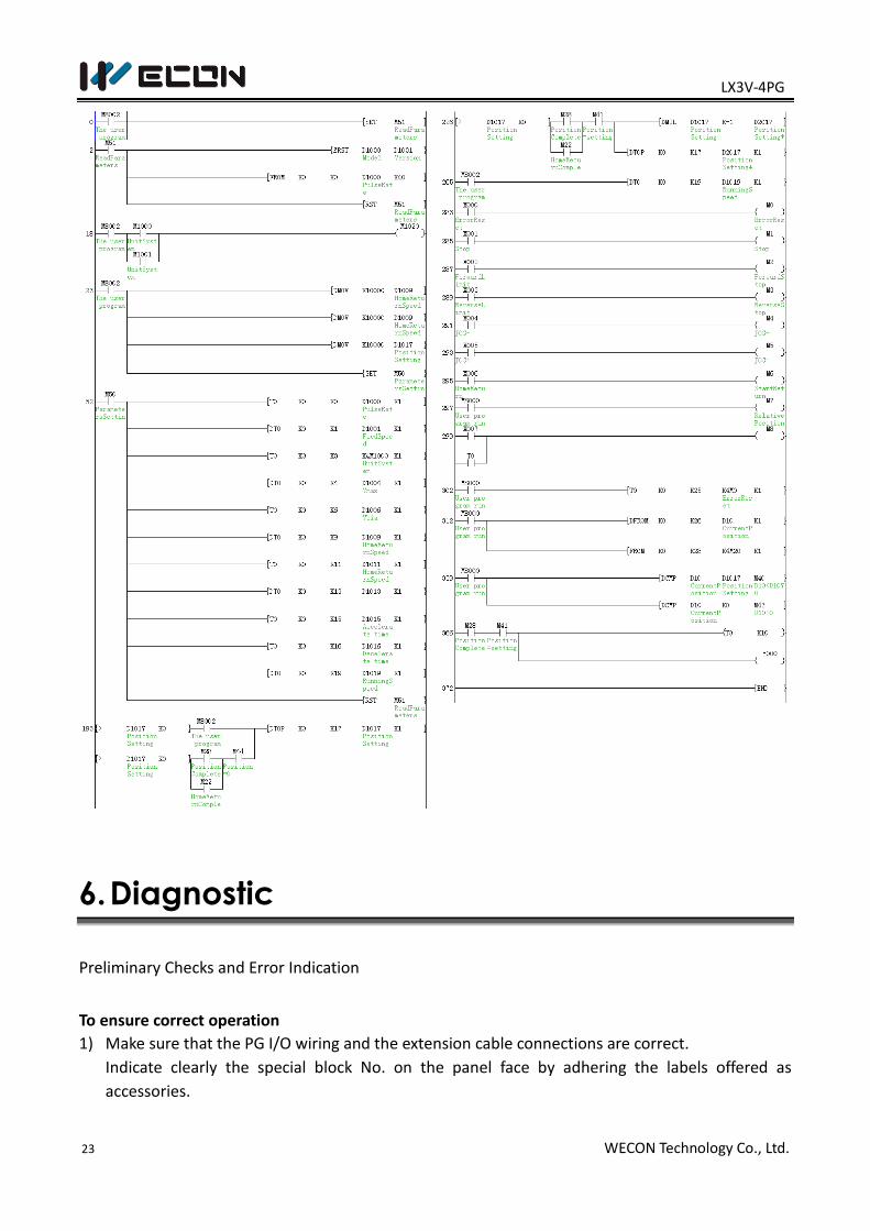
5. Example
The reciprocation by single-speed positioning
Do not put the load on the motor for safety when you confirm the operation according to this
program example.
1) The position of the motor moves to the machine home position according to the home position
return start instruction now. (Machine home position return operation) At this time, the
machine home position address is assumed to be “0”.
2) While the forward or reverse button is pressed and held, the motor is driven forward or in
reverse. (Jog operation)
3) The value of the motor advances 10000 mm according to the automatic drive start instruction.
4) After wards, Y000 is turned on for two seconds as a stand by display stopping and at this time.
Finally, the value of the motor retreats by 10000 mm. (Single-speed positioning operation)
Input Output 4PG terminals
X000: error reset X005:JOG- operation
Y000:
display
DOG: input return signal
X001: stop command X006: start home return FP: Pulse output to servo amplifier
PP
X002: stop forward
pulse X007: Single-speed
positioning operation
RP: pulse output direction
X003: stop reverse
pulse
X004: JOG+ operation
LX3V-4PG
23 WECON Technology Co., Ltd.
6. Diagnostic
Preliminary Checks and Error Indication
To ensure correct operation
1) Make sure that the PG I/O wiring and the extension cable connections are correct.
Indicate clearly the special block No. on the panel face by adhering the labels offered as
accessories.
LX3V-4PG
24 WECON Technology Co., Ltd.
2) In any positioning operation, the specified data should be written preliminarily to the BFMs #0
to #24, and then the BFM #25 should give an appropriate command. Otherwise, the PG does
not function.
Error indication
1) LED indication
The PG panel has the following LEDs:
Power indication: The POWER LED is lighted when 5 V power is supplied from the PLC.
Input indication: When DOG or X is received by the PG, the corresponding LED is lighted
respectively.
Output indication: When FP or RP is output by the PG, the corresponding LED is lighted
respectively.
Error indication: When an error occurs, the ERR LED flashes.
2) Error check
Errors are indicated by BFM#28 bit 7. Various errors can be checked by reading the contents of
the BFM #29 to the PC.
Version: V1.0.1
Date: Mar 2018