Embed Size (px)
DESCRIPTION
IT3230/ST/CMS. Design, construction and installation of a double loop fluorocarbon 150 kW cooling plant for the CMS Tracker and Preshower detectors. M. Battistin, M. Bosteels, M. Pimenta, P. Tropea. CMS Tracker and Preshower cooling plant General scheme. UXC55. USC55. - PowerPoint PPT Presentation
Citation preview
22-Jan-04 P. Tropea - JCOV 1
TS-CV-Detector Cooling
Design, construction and Design, construction and installation of a double loop installation of a double loop
fluorocarbon 150 kW cooling plant fluorocarbon 150 kW cooling plant for the CMS Tracker and Preshower for the CMS Tracker and Preshower
detectorsdetectors
M. Battistin, M. Bosteels, M. Pimenta, P. Tropea
IT3230/ST/CMSIT3230/ST/CMS
22-Jan-04 P. Tropea - JCOV 2
TS-CV-Detector Cooling
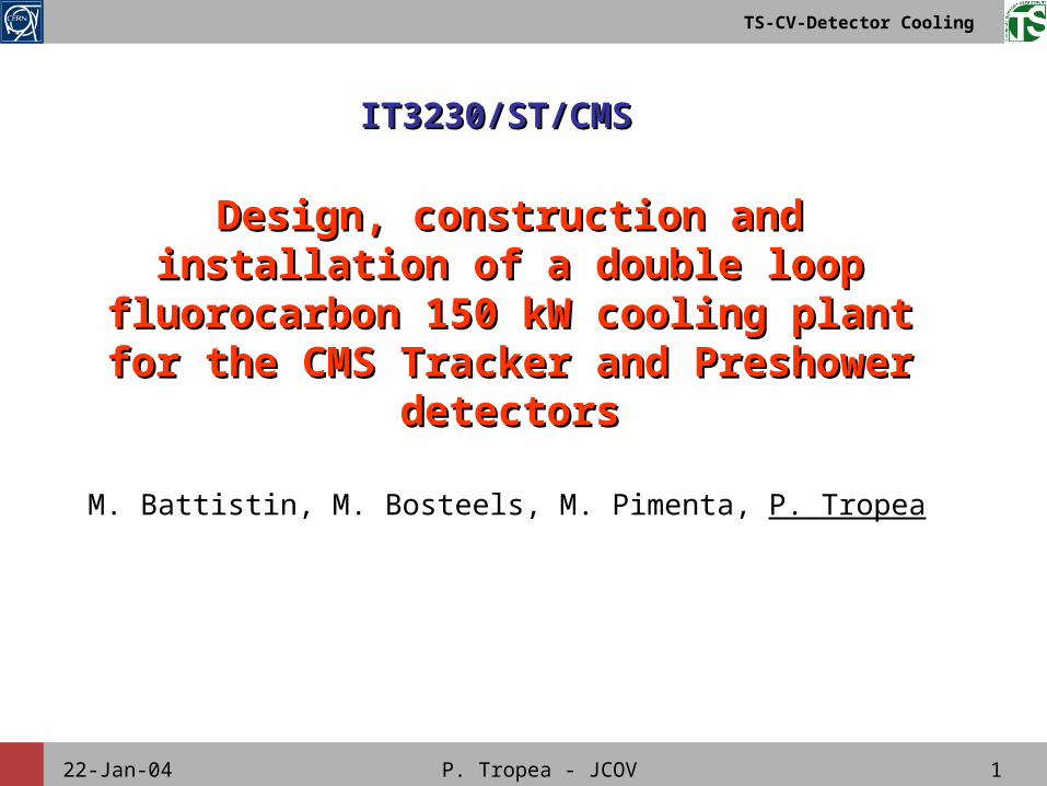
CMS Tracker and Preshower cooling CMS Tracker and Preshower cooling plant General schemeplant General scheme
Compressors
Condenser
Chilled water
To Silicon Stripand Pixelcooling circuits
Primary cooling
3 standardcooling units
To ThermalScreen andPreshowercooling circuits
4 cooling units withemergency fridge
Secondary cooling
USC55
UXC55
22-Jan-04 P. Tropea - JCOV 3
TS-CV-Detector Cooling
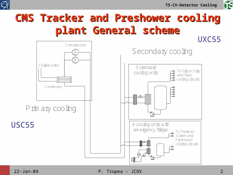
Primary cooling plant functional Primary cooling plant functional schemescheme
E-1
E-2
V-1
E-3
V-2
V-3
V-4
V-5
V-6
E-4
E-5
V-7E-6
V-8
I-1
V-9
E-7
V-10
V-11 E-8
V-12V-13
E-9
V-14V-15
E-10
V-16
V-17 E-11
V-18V-19
E-12
V-20V-21
V-22 I-2
I-3P
I-4
I-5
T
I-6
W
I-7
I-8
P
Cooling systemCooling system: evaporative
FluidFluid: R410A
PowerPower: 150 kW
InstallationInstallation: USC55, zone CV
Chilled water
R410A to/from UXC55
22-Jan-04 P. Tropea - JCOV 4
TS-CV-Detector Cooling
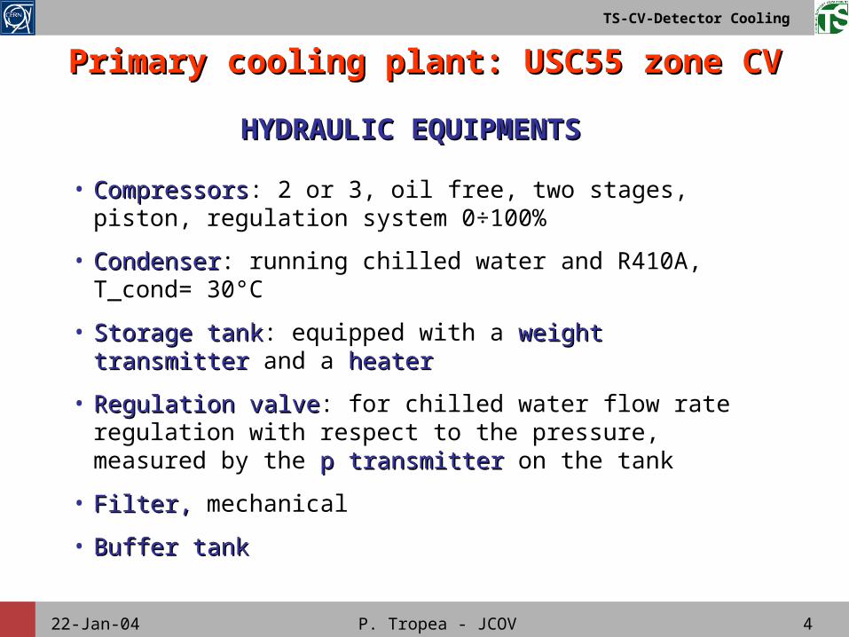
Primary cooling plant: USC55 zone CVPrimary cooling plant: USC55 zone CV
• CompressorsCompressors: 2 or 3, oil free, two stages, piston, regulation system 0÷100%
• CondenserCondenser: running chilled water and R410A, T_cond= 30°C
• Storage tankStorage tank: equipped with a weight transmitterweight transmitter and a heaterheater
• Regulation valveRegulation valve: for chilled water flow rate regulation with respect to the pressure, measured by the pp transmittertransmitter on the tank
• Filter, Filter, mechanical
• Buffer tankBuffer tank
HYDRAULIC EQUIPMENTSHYDRAULIC EQUIPMENTS
22-Jan-04 P. Tropea - JCOV 5
TS-CV-Detector Cooling
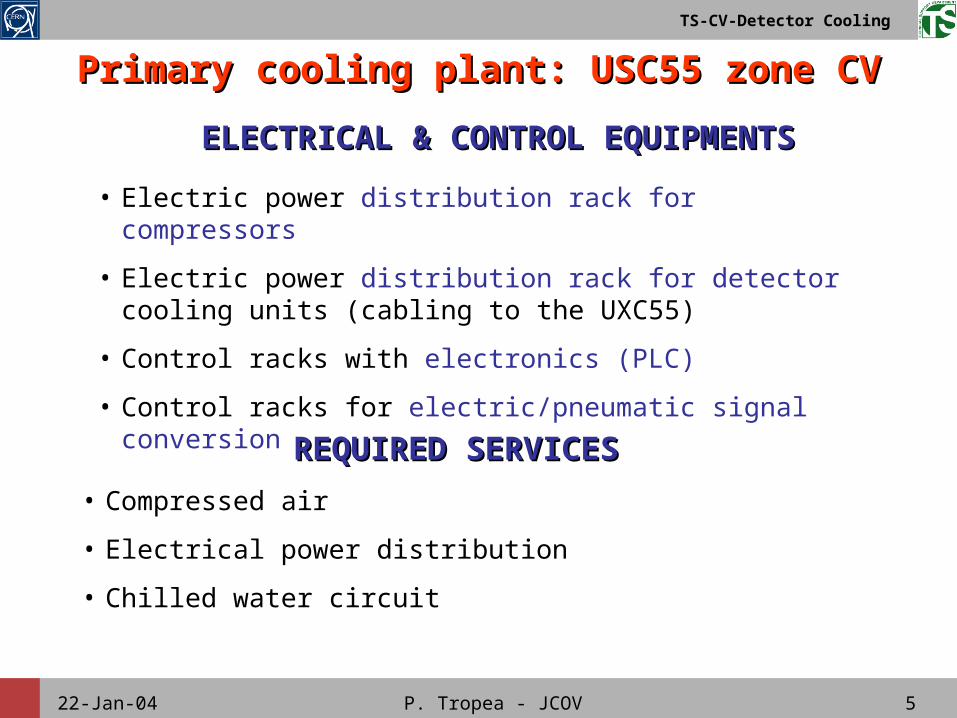
Primary cooling plant: USC55 zone CVPrimary cooling plant: USC55 zone CV
• Compressed air
• Electrical power distribution
• Chilled water circuit
REQUIRED SERVICESREQUIRED SERVICES
ELECTRICAL & CONTROL EQUIPMENTSELECTRICAL & CONTROL EQUIPMENTS
• Electric power distribution rack for compressors
• Electric power distribution rack for detector cooling units (cabling to the UXC55)
• Control racks with electronics (PLC)
• Control racks for electric/pneumatic signal conversion
22-Jan-04 P. Tropea - JCOV 6
TS-CV-Detector Cooling
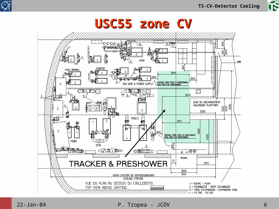
USC55 zone CVUSC55 zone CV
22-Jan-04 P. Tropea - JCOV 7
TS-CV-Detector Cooling
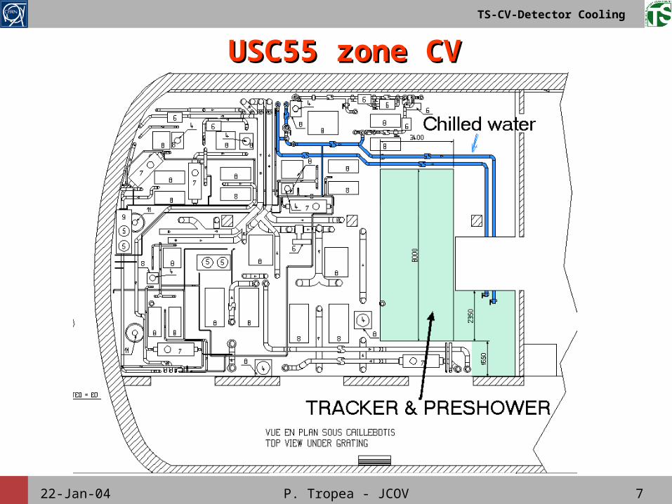
USC55 zone CVUSC55 zone CV
22-Jan-04 P. Tropea - JCOV 8
TS-CV-Detector Cooling
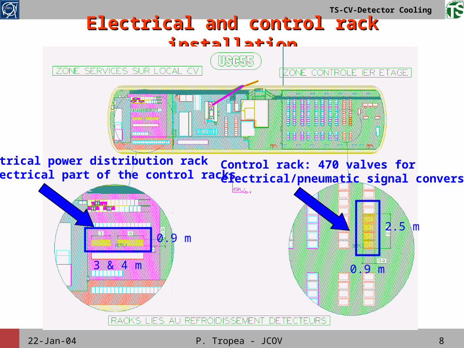
Electrical and control rack installationElectrical and control rack installation
Control rack: 470 valves for electrical/pneumatic signal conversion
Electrical power distribution rack & electrical part of the control racks
3 & 4 m
0.9 m2.5 m
0.9 m
22-Jan-04 P. Tropea - JCOV 9
TS-CV-Detector Cooling
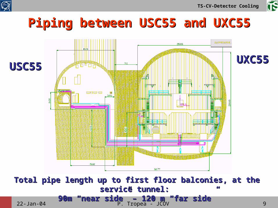
USC55USC55UXC55UXC55
Total pipe length up to first floor balconies, at the service Total pipe length up to first floor balconies, at the service tunnel: tunnel:
90m “near side” – 120 m “far side”90m “near side” – 120 m “far side”
Piping between USC55 and UXC55Piping between USC55 and UXC55
22-Jan-04 P. Tropea - JCOV 10
TS-CV-Detector Cooling
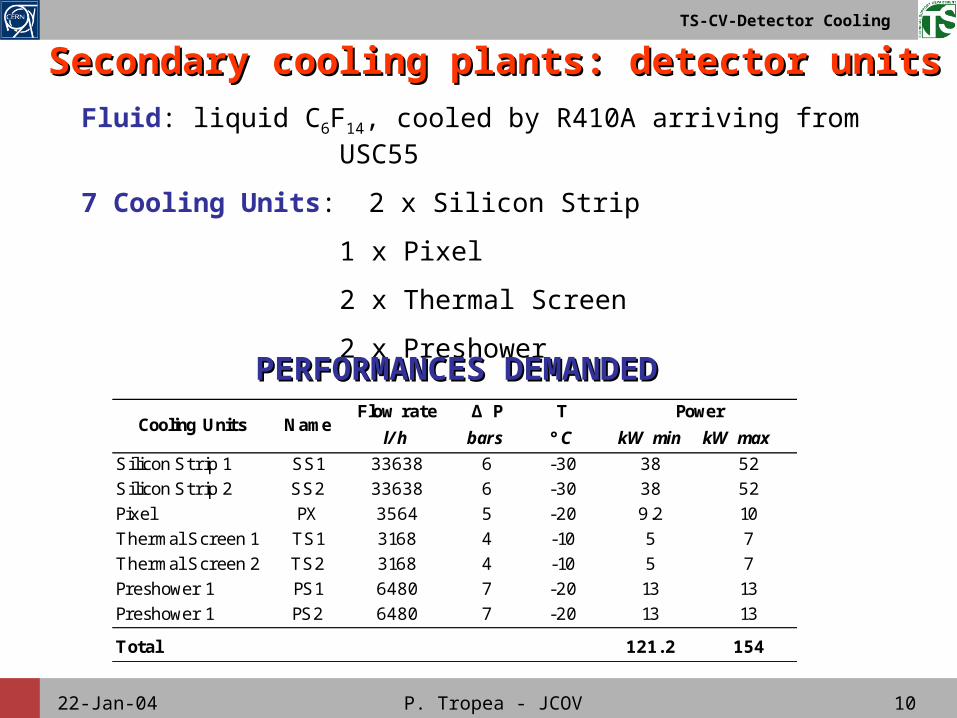
Fluid: liquid C6F14, cooled by R410A arriving from USC55
7 Cooling Units: 2 x Silicon Strip
1 x Pixel
2 x Thermal Screen
2 x Preshower
Secondary cooling plants: detector unitsSecondary cooling plants: detector units
PERFORMANCES DEMANDEDPERFORMANCES DEMANDEDFlow rate Δ P T
l/h bars °C kW min kW max
Silicon Strip 1 SS1 33638 6 -30 38 52Silicon Strip 2 SS2 33638 6 -30 38 52Pixel PX 3564 5 -20 9.2 10Thermal Screen 1 TS1 3168 4 -10 5 7Thermal Screen 2 TS2 3168 4 -10 5 7Preshower 1 PS1 6480 7 -20 13 13Preshower 1 PS2 6480 7 -20 13 13
Total 121.2 154
Cooling Units NamePower
22-Jan-04 P. Tropea - JCOV 11
TS-CV-Detector Cooling
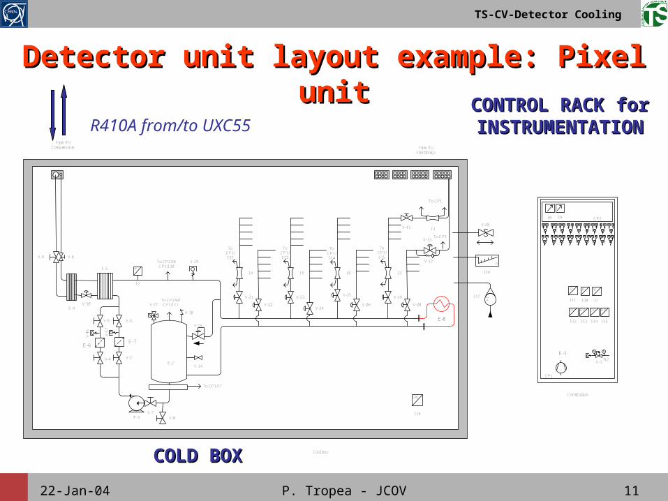
Detector unit layout example: Pixel Detector unit layout example: Pixel unitunit
CP1
Control rack
CP2
E-1N2
V-1E-2
E-3
V-2
V-3
V-4
V-5
E-4
E-5
V-6
V-7
To CP1
To CP1
To CP2/I-8CP1/I-10
From/ToCompressors
Cool box
V-8
From/ToElectronics
V-9
V-10
V-11 I-1
V-13
V-14
I-2
T
V-15
V-1
6
V-1
7
E-6E-7
V-18
I-3I-4 I-5 I-6
V-27To CP2/I-9CP1/I-11
To CP1/I-7
I-7
I-8 I-9
I-10
P
I-11
P W
I-12
DP
I-13
DP
I-14
DP
I-15
DP
ToCP1/I-12
ToCP1/I-13
ToCP1/I-14
ToCP1/I-15
I-16
DW
FII-17
P
I-18
V-28
E-8
V-21
V-22
V-23 V-25
V-24V-26 V-20
V-19
V-29 V-12
COLD BOXCOLD BOX
CONTROL RACK for CONTROL RACK for INSTRUMENTATIONINSTRUMENTATIONR410A from/to UXC55
22-Jan-04 P. Tropea - JCOV 12
TS-CV-Detector Cooling
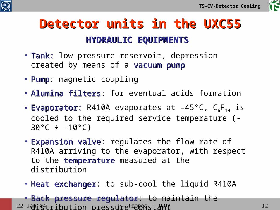
Detector units in the UXC55Detector units in the UXC55
• Tank: Tank: low pressure reservoir, depression created by means of a vacuum pumpvacuum pump
• PumpPump: magnetic coupling
• Alumina filtersAlumina filters: for eventual acids formation
• Evaporator:Evaporator: R410A evaporates at -45°C, C6F14 is cooled to the required service temperature (-30°C ÷ -10°C)
• Expansion valveExpansion valve: regulates the flow rate of R410A arriving to the evaporator, with respect to the temperaturetemperature measured at the distribution
• Heat exchangerHeat exchanger: to sub-cool the liquid R410A
• Back pressure regulatorBack pressure regulator: to maintain the distribution pressure constant
HYDRAULIC EQUIPMENTSHYDRAULIC EQUIPMENTS
22-Jan-04 P. Tropea - JCOV 13
TS-CV-Detector Cooling
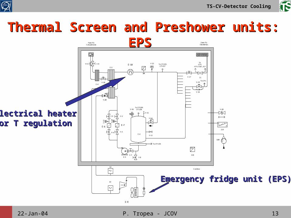
Thermal Screen and Preshower units: Thermal Screen and Preshower units: EPSEPS
I-2
E-2
E-3
V-2
V-3
V-4
V-5
E-4
E-5
V-7
To CP2/I-5CP1/I-7
From/ToCompressors
Cool box
V-8
V-10
V-11
V-12
V-1
3
V-1
4
E-6E-7
V-15
V-16To CP2/I-6
CP1/I-8
To CP1/I-9
To CP1
To-CP1
-CP1/ I-10...I-17
From/ToElectronics
V-17 I-1
V-19
E-8
V-20
E-9
E-10
I-3
I-4
T
I-18
DW
FII-20
P
I-19
V-28
V-6 V-9 V-22
V-18
Emergency fridge unit (EPS)Emergency fridge unit (EPS)
Electrical heater Electrical heater for T regulationfor T regulation
22-Jan-04 P. Tropea - JCOV 14
TS-CV-Detector Cooling
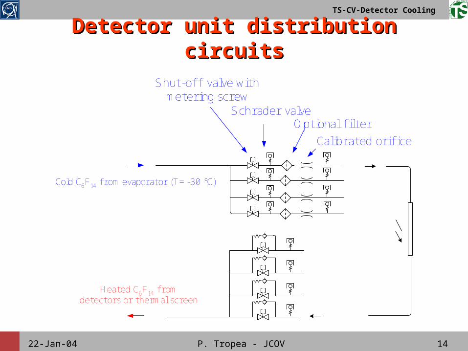
Detector unit distribution circuitsDetector unit distribution circuits
Shut-off valve withmetering screw
Calibrated orifice
Schrader valve
Cold C6F14 f rom evaporator (T= -30 °C)
Heated C6F14 f romdetectors or thermal screen
Optional fi lter
22-Jan-04 P. Tropea - JCOV 15
TS-CV-Detector Cooling
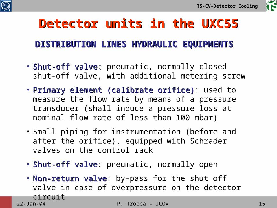
Detector units in the UXC55Detector units in the UXC55
• Shut-off valve: Shut-off valve: pneumatic, normally closed shut-off valve, with additional metering screw
• Primary element (calibrate orifice)Primary element (calibrate orifice): used to measure the flow rate by means of a pressure transducer (shall induce a pressure loss at nominal flow rate of less than 100 mbar)
• Small piping for instrumentation (before and after the orifice), equipped with Schrader valves on the control rack
• Shut-off valveShut-off valve: pneumatic, normally open
• Non-return valveNon-return valve: by-pass for the shut off valve in case of overpressure on the detector circuit
DISTRIBUTION LINES HYDRAULIC EQUIPMENTSDISTRIBUTION LINES HYDRAULIC EQUIPMENTS
22-Jan-04 P. Tropea - JCOV 16
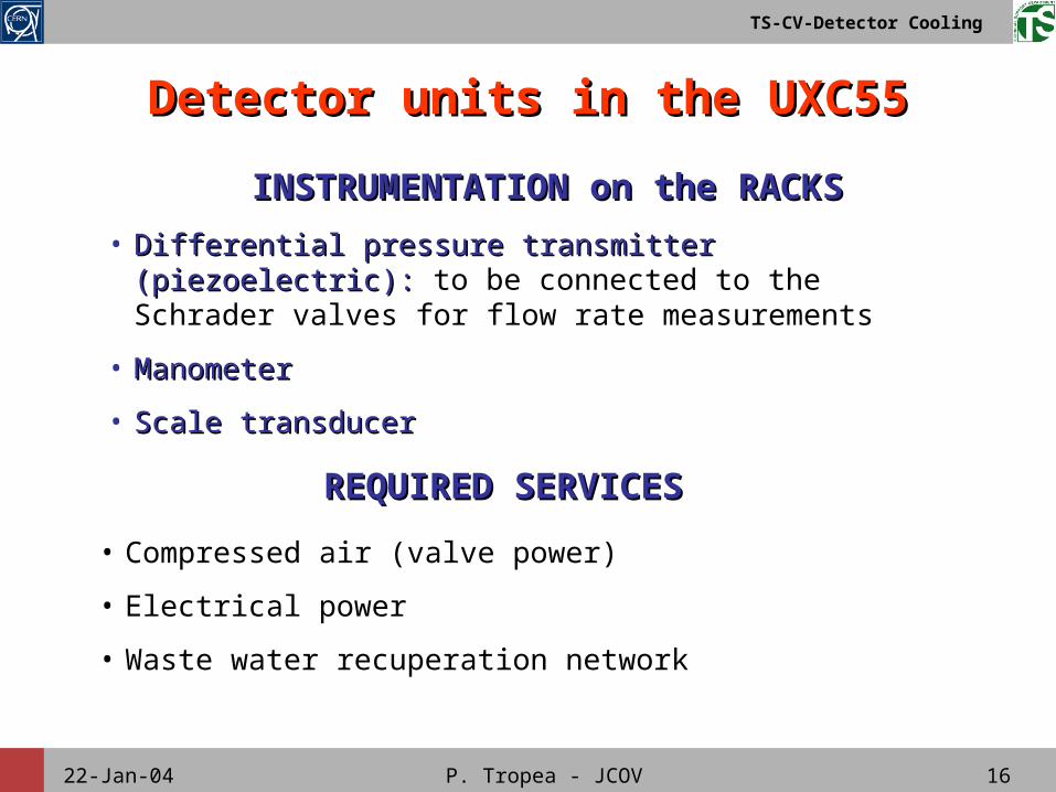
TS-CV-Detector Cooling
REQUIRED SERVICESREQUIRED SERVICES
INSTRUMENTATION on the RACKSINSTRUMENTATION on the RACKS
• Differential pressure transmitter (piezoelectric):Differential pressure transmitter (piezoelectric): to be connected to the Schrader valves for flow rate measurements
• ManometerManometer
• Scale transducerScale transducer
• Compressed air (valve power)
• Electrical power
• Waste water recuperation network
Detector units in the UXC55Detector units in the UXC55
22-Jan-04 P. Tropea - JCOV 17
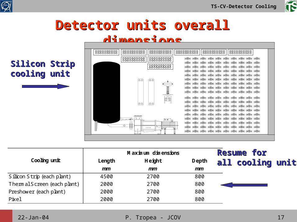
TS-CV-Detector Cooling
Detector units overall dimensionsDetector units overall dimensions
Length Height Depth
mm mm mm
Silicon Strip (each plant) 4500 2700 800Thermal Screen (each plant) 2000 2700 800Preshower (each plant) 2000 2700 800Pixel 2000 2700 800
Maximum dimensionsCooling unit
DN40 - PN10
CASTER MTA2020
Silicon StripSilicon Stripcooling unitcooling unit
Resume for Resume for all cooling unitsall cooling units
22-Jan-04 P. Tropea - JCOV 18
TS-CV-Detector Cooling
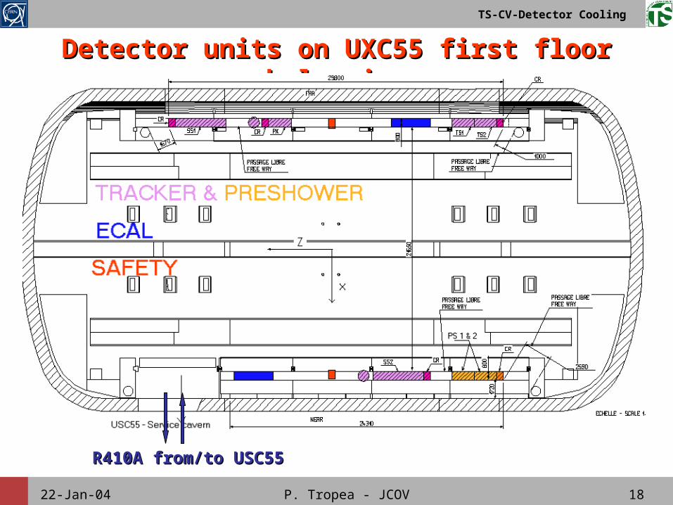
Detector units on UXC55 first floor balconiesDetector units on UXC55 first floor balconies
R410A from/to USC55R410A from/to USC55
22-Jan-04 P. Tropea - JCOV 19
TS-CV-Detector Cooling
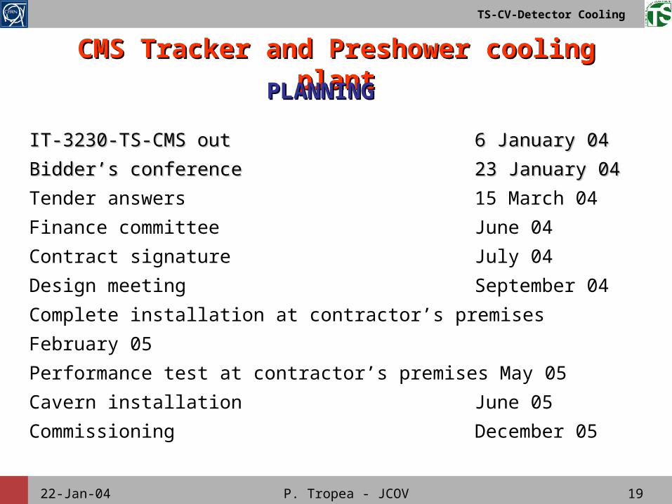
CMS Tracker and Preshower cooling CMS Tracker and Preshower cooling plantplantPLANNINGPLANNING
IT-3230-TS-CMS outIT-3230-TS-CMS out 6 January 046 January 04
Bidder’s conferenceBidder’s conference 23 January 0423 January 04
Tender answers 15 March 04
Finance committee June 04
Contract signature July 04
Design meeting September 04
Complete installation at contractor’s premises February 05
Performance test at contractor’s premises May 05
Cavern installation June 05
Commissioning December 05
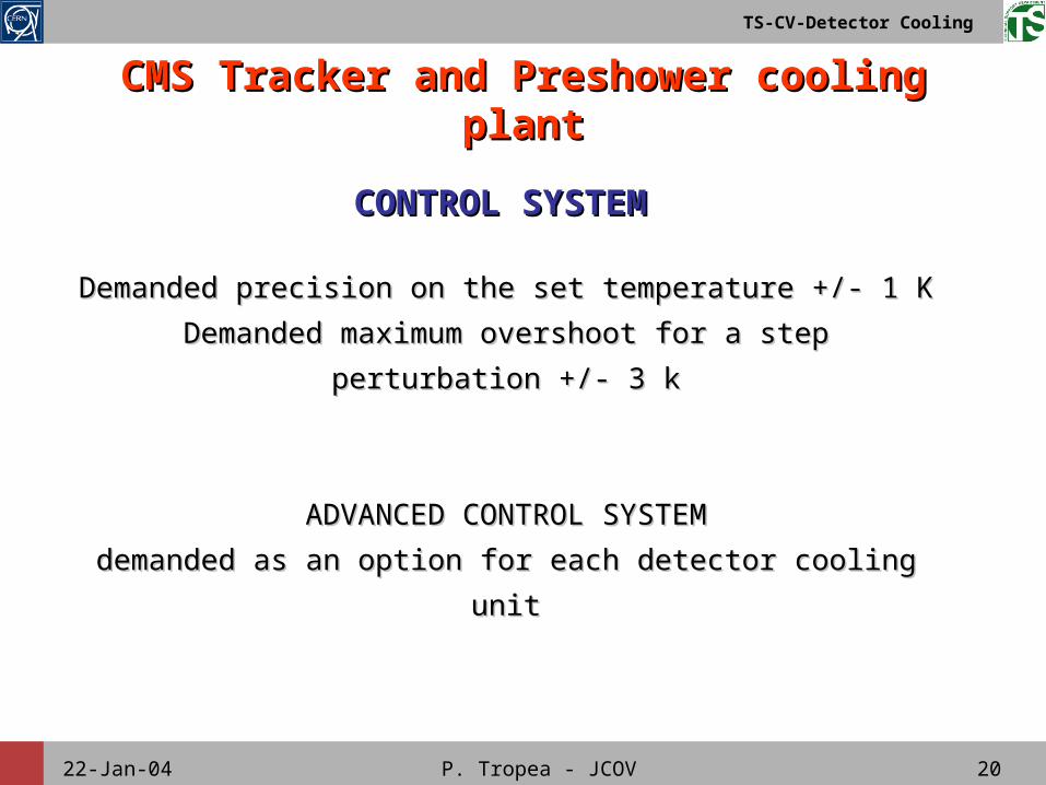
22-Jan-04 P. Tropea - JCOV 20
TS-CV-Detector Cooling
CMS Tracker and Preshower cooling CMS Tracker and Preshower cooling plantplant
CONTROL SYSTEMCONTROL SYSTEM
Demanded precision on the set temperature +/- 1 KDemanded precision on the set temperature +/- 1 K
Demanded maximum overshoot for a step perturbation +/- Demanded maximum overshoot for a step perturbation +/-
3 k3 k
ADVANCED CONTROL SYSTEMADVANCED CONTROL SYSTEM
demanded as an option for each detector cooling unitdemanded as an option for each detector cooling unit