Embed Size (px)
Citation preview
Service
Service
Contents Page
1. Technical Specifications, Connections and Chassis Overview 2 - 32. Safety & Maintenance Instructions, Warnings and Notes 4 - 53. Directions for Use 6 - 324. Mechanical Instructions 335. Faultfinding 34 -406. Block Diagram, I2C Overview Block Diagram 41
2 I C 42-437. Electrical Diagrams and Test Point with waveform diagram
Power Supply (Diagram A1) 44Line Deflection (Diagram A2) 44 Frame Deflection (Diagram A3) 45Tuner IF (Diagram A4) 45MCU,Video IF and Sound IF (Diagram A5) 46BTSC (Stereo/SAP) Decoder(Diagram A6) 47Video Source Switching (Diagram A7) 47Side AV (Diagram A8) 48Audio Amplifier (Diagram A9) 48CRT Panel (Diagram B) 49 Transistor Test Voltage 49Test point with Waveform Diagram 50 - 51
8. PCB diagram Main PCB 52 CRT PCB 53 MPX PCB 54 SIDE AV PCB 559. Alignment Procedures 56 - 6410. Circuit Description 6511. List of Abbreviations 66 - 6812. Spare Parts List 69 - 89
©Copyright 2001 Philips Consumer Electronics B.V. Eindhoven, The Netherlands.All
rights reserved. No part of this publication may be reproduced, stored in aretrieval system or
transmitted, in any form or by any means, electronic, mechanical, photocopying, or otherwise
without the prior permission of Philips.
Colour Television Chassis: M123A
1
Index:
Note: Below described specifications are not valid
for one product, but for the whole productrange.
See Product Survey for specific models. Figures can deviate slightly from the actual situation, due to different set executions.
1. Technical Specifications.2. Connections.3. Chassis Overview.
1.1 Technical Specifications 1.1.1 Reception Tuning system : PLL Colour systems : NTSC-M
Sound systems : FM-mono: FM-stereo
A/V connections : NTSC 3.58
Channel selections :TV:2-69,CATV:2-13,A-W,
W+1~W+84,A-5~A-1,5A
Aerial input : 75OHM, 1VP-P
Audio output : =3W+3W
Mains voltage : AC120V
Mains frequency : 60 Hz
Ambient temperature : + 5 to + 45 deg. C
Maximum humidity : 90 %
Power consumption : 80W
Standby Power consumption : <3W
1.1.2 Miscellaneous
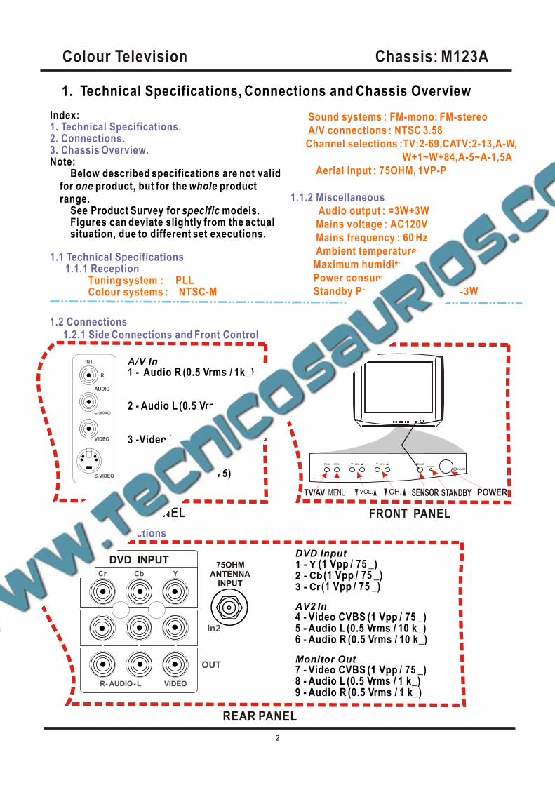
1.2 Connections1.2.1 Side Connections and Front Control
IN1
AUDIO
VIDEO
S-VIDEO
L (MONO)
R
SIDE AV PANEL
A/V In1 - Audio R (0.5 Vrms / 1k_)
2 - Audio L (0.5 Vrms / 1 k_)
3 -Video CVBS (1 Vpp / 75 )
4 - S-video (1 Vpp / 75)TV/AV SENSOR
STANDBY
POWER
FRONT PANEL
TV/AV SENSOR STANDBY POWER
DVD INPUT
YCbCr
In2
OUT
75OHMANTENNA
INPUT
1.2.2 Rear Connections
DVD Input1 - Y (1 Vpp / 75 _) 2 - Cb (1 Vpp / 75 _) 3 - Cr (1 Vpp / 75 _)
AV2 In4 - Video CVBS (1 Vpp / 75 _) 5 - Audio L (0.5 Vrms / 10 k_)6 - Audio R (0.5 Vrms / 10 k_)
Monitor Out7 - Video CVBS (1 Vpp / 75 _)8 - Audio L (0.5 Vrms / 1 k_)9 - Audio R (0.5 Vrms / 1 k_)
Colour Television Chassis: M123A
2
1. Technical Specifications, Connections and Chassis Overview
VIDEOAUDIOR L- -
REAR PANEL
Colour Television Chassis: M123A
3
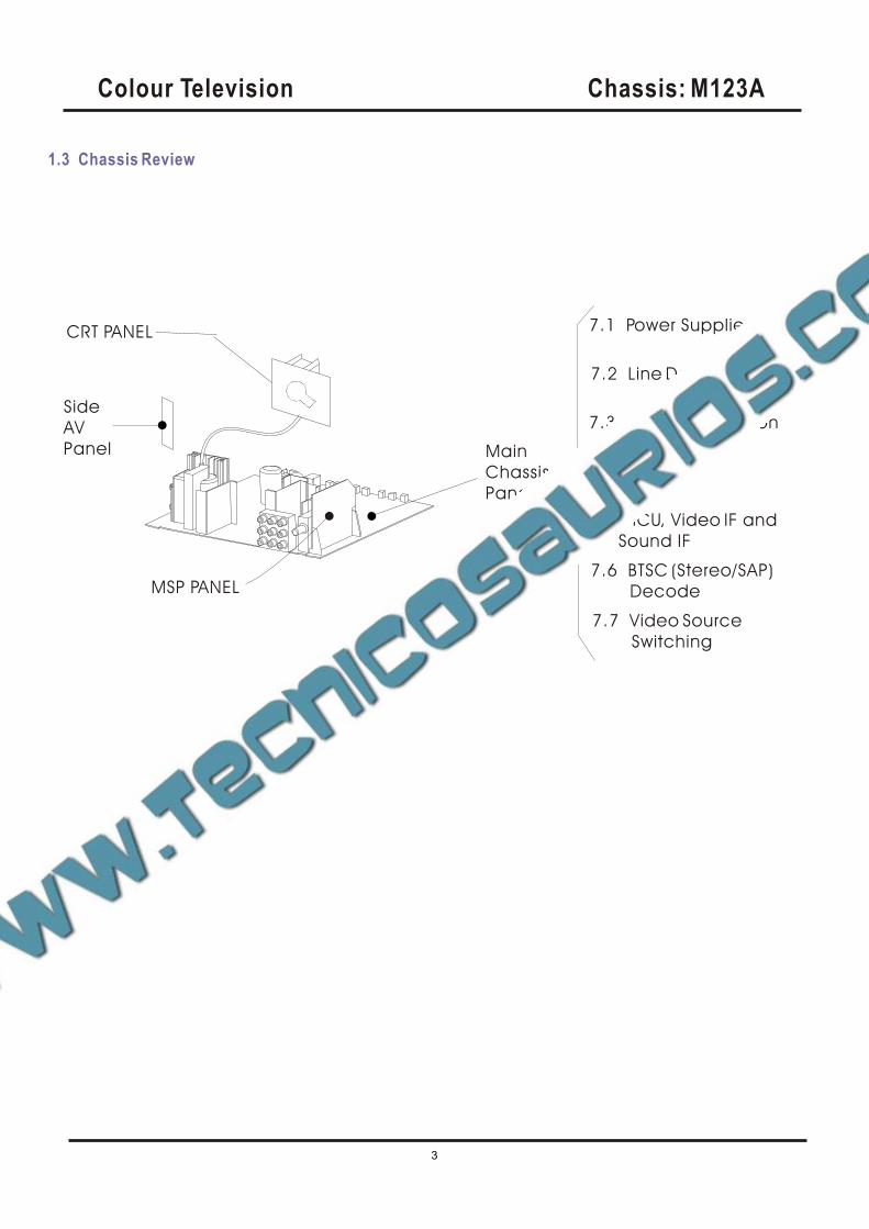
1.3 Chassis Review
7.1 Power Supplier
7.2 Line Deflection
7.3 Frame Deflection
7.4 Tuner IF
7.5 MCU, Video IF and
Sound IF
7.6 BTSC (Stereo/SAP)
Decode
7.7 Video Source
Switching
MSP PANEL
CRT PANEL
Main
Chassis
Panel
Side
AV
Panel
2. Safety & Maintenance Instructions, Warnings and Notes
2.1 Safety Instructions For Repairs
2.2 Maintenance Instructions
Safety regulations require that during a repair:
--Due to the 'hot' parts of this chassis, the set must be connected to the AC power via an
isolation transformer.
-- Safety components, indicated by the symbol _, should be replaced by components identical
to the original ones.
-- When replacing the CRT, safety goggles must be worn. Safety regulations require that after a
repair, the set must be returned in its original condition. Pay particular attention to the
following points:
-- General repair instruction: as a strict precaution, we advise you to re-solder the solder
connections through which the horizontal deflection current is flowing, in particular:
--- all pins of the line output transformer (LOT)
--- fly-back capacitor(s)
--- S-correction capacitor(s)
--- line output transistor
--- pins of the connector with wires to the deflection coil
--- other components through which the deflection current flows.
* Note: This re-soldering is advised to prevent bad connections due to metal fatigue in solder
connections and is therefore only necessary for television sets more than two years
Old.
-- Route the wire trees and EHT cable correctly and secure them with the mounted cable clamps.
-- Check the insulation of the AC power cord for external damage.
-- Check the strain relief of the AC power cord for proper function, to prevent the cord from
touching the CRT, hot components, or heat sinks.
-- Check the electrical DC resistance between the AC plug and the secondary side (only for sets
that have an isolated power supply). Do this as follows:
1. Unplug the AC power cord and connect a wire between the two pins of the AC plug.
2. Turn on the main power switch (keep the AC power cord unplugged!).
3. Measure the resistance value between the pins of the AC plug and the metal shielding of the
tuner or the aerial connection of the set. The reading should be between 4.5 M and 12 M .
4. Switch the TV OFF and remove the wire between the two pins of the AC plug.
Check the cabinet for defects, to prevent the possibility of the customer touching any
Internal parts.
It is recommended to have a maintenance inspection carried out by qualified service
personnel. The interval depends on the usage conditions:
--- When the set is used under normal circumstances, for example in a living room, the
recommended interval is hree to five years.
--- When the set is used in an environment with higher dust,grease or moisture levels, for
example in a kitchen, the recommended interval is one year.
--- The maintenance inspection includes the following actions
1. Perform the 'general repair instruction' noted above.
2. Clean the power supply and deflection circuitry on the chassis.
3. Clean the picture tube panel and the neck of the picture tube.
Colour Television Chassis: M123A
4
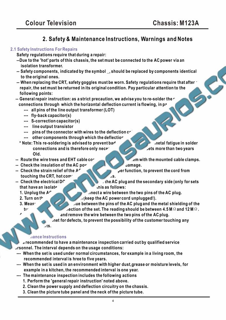
--- In order to prevent damage to ICs and transistors, avoid all high voltage flashovers. In order to
prevent damage to the picture tube, use the method shown in Fig. 2-1, to discharge the picture
tube. Use a high voltage probe and a multi-meter (position VDC). Discharge until the meter
reading is 0 V (after approx. 30 s).
---- All ICs and many other semiconductors are susceptible to electrostatic discharges (ESD)
Careless handling during repair can reduce life drastically. When repairing, make sure that you
are connected with the same potential as the mass of the set by a wristband with resistance.
Keep components and tools also at this potential. Available ESD protection equipment:
--- Complete kit ESD3 (small tablemat, wristband, connection box, extension cable, and ground
cable)
--- Wristband tester
--- Together with the deflection unit and any multi-pole unit, flat square picture tubes form an
integrated unit. The deflection and the multi-pole units are set optimally at the factory.
Adjustment of this unit during repair is therefore not recommended.
---- Be careful during measurements in the high voltage section and on the picture tube.
Never replace modules or other components while the unit is switched ON.
---- When you align the set, use plastic rather than metal tools. This will prevent any short circuits
and the danger of a circuit becoming unstable.
--- Measure the voltages and waveforms with regard to the chassis (= tuner) ground (), or hot
ground (), depending on the area of circuitry being tested.
---- The voltages and waveforms shown in the diagrams are indicative. Measure them in the Service
Default Mode (see chapter 5) with a color bar signal and stereo sound (L: 3 kHz, R: 1 kHz unless
stated otherwise) and picture carrier at 475.25 MHz (PAL) or 61.25 MHz (NTSC, channel 3).
---- Where necessary, measure the waveforms and voltages with () and without () aerial signal.
Measure the voltages in the power supply section both in normal operation () and in standby ().
These values are indicated by means of the appropriate symbols.
---- The picture tube panel has printed spark gaps. Each spark gap is connected between an
electrode of the picture tube and the Aquadag coating.
--- The semiconductors indicated in the circuit diagram and in the parts lists are completely
interchangeable per position with the semiconductors in the unit, irrespective of the type
Indication on these semiconductors.
2.3 Warnings
_
4822 344 13999.
2.4 Notes
Colour Television Chassis: M123A
5
3. Directions for Use3.1 Basic Cable TV Connection
DVD INPUT
YCbCr
IN2
OUT
VIDEOAUDIOR L- -
75OHMANTENNA
INPUT
DVD INPUT
YCbCr
IN2
OUT
VIDEOAUDIOR L- -
75OHMANTENNA
INPUT
75 OHMANTENNA
INPUT
75 OHMANTENNA
INPUT
Cable TV company
Cable TV company
Cable Box
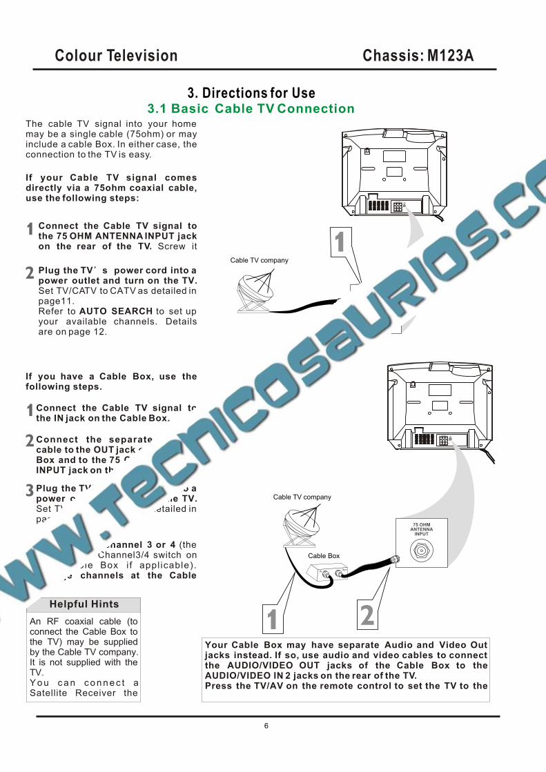
The cable TV signal into your home may be a single cable (75ohm) or mayinclude a cable Box. In either case, theconnection to the TV is easy.
If your Cable TV signal comesdirectly via a 75ohm coaxial cable,use the following steps:
Connect the Cable TV signal tothe 75 OHM ANTENNA INPUT jackon the rear of the TV. Screw it
Plug the TV s power cord into a power outlet and turn on the TV.Set TV/CATV to CATV as detailed in page11.Refer to AUTO SEARCH to set up your available channels. Detailsare on page 12.
If you have a Cable Box, use thefollowing steps.
Connect the Cable TV signal tothe IN jack on the Cable Box.
Connect the separate coaxialcable to the OUT jack on the CableBox and to the 75 OHM ANTENNAINPUT jack on the rear of the TV.
Plug the TV s power cord into a power outlet and turn on the TV.Set TV/CATV to CATV as detailed in page11.
Set the TV to channel 3 or 4 (the same as the Channel3/4 switch onyour Cable Box i f appl icable). Change channels at the Cable
An RF coaxial cable (to connect the Cable Box to the TV) may be supplied by the Cable TV company. It is not supplied with the TV.Y o u c a n c o n n e c t a Satellite Receiver the
Helpful Hints
Your Cable Box may have separate Audio and Video Out jacks instead. If so, use audio and video cables to connect the AUDIO/VIDEO OUT jacks of the Cable Box to the
Press the TV/AV on the remote control to set the TV to theAUDIO/VIDEO IN 2 jacks on the rear of the TV.
Colour Television Chassis: M123A
6
DVD INPUT
YCbCr
IN2
OUT
VIDEOAUDIOR L- -
75OHMANTENNA
INPUT
DVD INPUT
YCbCr
IN2
OUT
VIDEOAUDIOR L- -
75OHMANTENNA
INPUT
75 OHMANTENNA
INPUT
UHF/VHFCombiner
75-300 Ohm Adapter
VHFAntenna
VHFAntenna
UHFAntenna
Rear of TV
OR
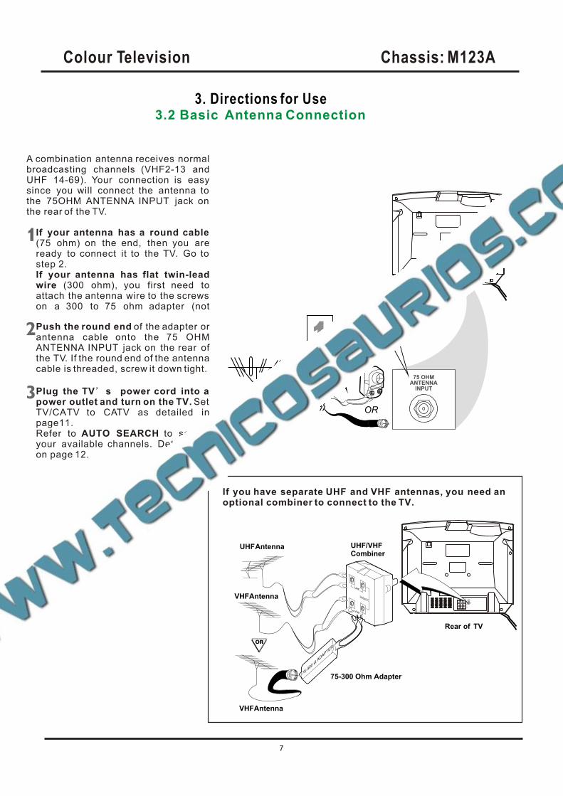
A combination antenna receives normalbroadcasting channels (VHF2-13 andUHF 14-69). Your connection is easysince you will connect the antenna to the 75OHM ANTENNA INPUT jack on the rear of the TV.
If your antenna has a round cable (75 ohm) on the end, then you areready to connect it to the TV. Go to step 2.If your antenna has flat twin-leadwire (300 ohm), you first need toattach the antenna wire to the screws on a 300 to 75 ohm adapter (not
Push the round end of the adapter orantenna cable onto the 75 OHMANTENNA INPUT jack on the rear ofthe TV. If the round end of the antennacable is threaded, screw it down tight.
Plug the TV s power cord into a power outlet and turn on the TV. SetTV/CATV to CATV as detailed inpage11.Refer to AUTO SEARCH to set up your available channels. Details are on page 12.
If you have separate UHF and VHF antennas, you need an optional combiner to connect to the TV.
3. Directions for Use3.2 Basic Antenna Connection
Colour Television Chassis: M123A
7
DVD INPUT
YCbCr
DVD INPUT
YCbCr
IN2
OUT
VIDEOAUDIOR L- -
75OHMANTENNA
INPUT
DVD INPUT
YCbCr
IN2
OUT
VIDEOAUDIOR L- -
75OHMANTENNA
INPUT
DVD INPUT
YCbCr
IN2
OUT
VIDEOAUDIOR L- -
75OHMANTENNA
INPUT
IN1
AUDIO
VIDEO
S-VIDEO
L (MONO)
R
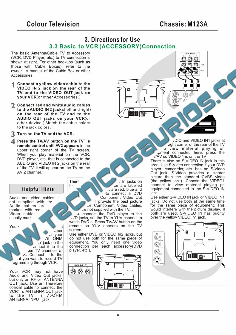
The basic Antenna/Cable TV to Accessory(VCR, DVD Player, etc.) to TV connection is shown at right. For other hookups (such as those with Cable Boxes), refer to the owner s manual of the Cable Box or other Accessories.
Connect a yellow video cable to the VIDEO IN 2 jack on the rear of the TV and to the VIDEO OUT jack onyour VCR(or )other Accessories.
Connect red and white audio cablesto the AUDIO IN 2 jacks(left and right)on the rear of the TV and to the AUDIO OUT jacks on your VCR(orother device.) Match the cable colorsto the jack colors.
Press the TV/AV button on the TV sremote control until AV2 appears in the upper right corner of the TV screen. When you play material on the VCR, DVD player, etc. that is connected to the AUDIO and VIDEO IN 2 jacks on the rear of the TV, it will appear on the TV on the AV 2 channel.
Helpful Hints
Audio and video cables are not supplied with the TV.Audio cables are usually marked with red and white. Video cables (CVBS) are usually marked with yellow.
You can connect the antenna or Cable TV signal to either the ANTENNA IN jack on your VCR or to the 75 OHM
Your VCR may not have Audio and Video Out jacks, but only an RF or ANTENNAOUT jack. Use an Therefore coaxial cable to connect the VCR s ANTENNA OUT jack to the TV s 75OHM ANTENNA INPUT jack.
ANTENNA INPUT jack on the TV. If you connect it to the VCR, choose TV channels at the VCR. Connect it to the VCR if you want to record TV programming through VCR.
There are Component Video In jacks on the rear of the TV. These are labelled DVD Y, Cb and Cr and are red, blue and green. Use these to connect a DVD player that has Component Video Out jacks. This will provide the best picture quality. Use Component Video cables, which are not supplied with the TV.If you connect the DVD player to the DVD jacks, set the TV to YUV channel to watch DVD s. Press TV/AV button on the remote so YUV appears on the TV screen.Use either DVD or VIDEO In2 jacks, but do not use both for the same piece of equipment. You only need one video connection per each accessory(DVD player, etc.).
There are AUDIO and VIDEO IN1 jacks at the lower-right corner of the rear of the TV set. To view material playing on equipment connected here, press the TV/AV so VIDEO 1 is on the TV.There is also an S-VIDEO IN jack in this area. Use S-Video connection if your DVD player, camcorder, etc. has an S-Video Out jack. S-Video provides a clearer picture than the standard CVBS video (the yellow jack). Choose the VIDEO1 channel to view material playing pn equipment connected to the S-VIDEO IN jack.Use either S-VIDEO IN jack or VIDEO IN1 jacks. Do not use both at the same time for the same piece of equipment. This would interfere with the picture display. If both are used, S-VIDEO IN has priority over the yellow VIDEO In1 jack.
DVD INPUT
YCbCr
IN2
OUT
VIDEOAUDIOR L- -
R
R R
Turn on the TV and the VCR.
3. Directions for Use3.3 Basic to VCR (ACCESSORY)Connection
Colour Television Chassis: M123A
8
3. Directions for Use3.4 Basic to Antenna Connection
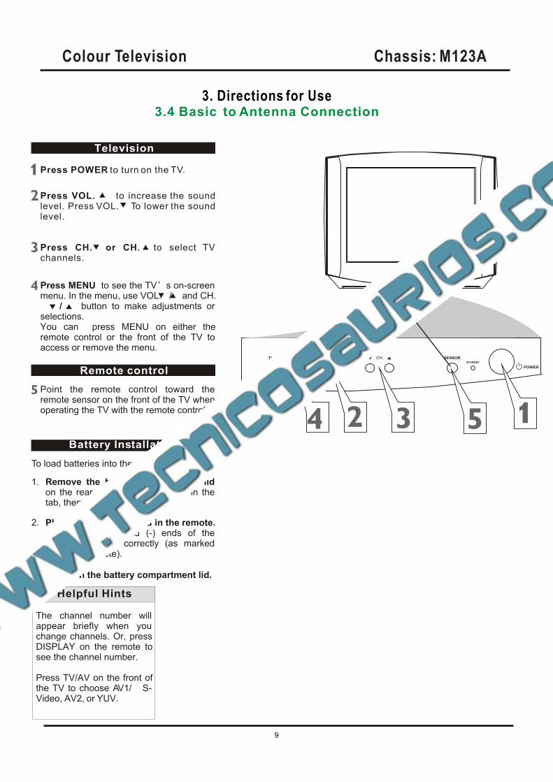
Press POWER to turn on the TV.
Press VOL. to increase the soundlevel. Press VOL. To lower the soundlevel.
Press CH. or CH. to select TV channels.
Press MENU to see the TV s on-screen menu. In the menu, use VOL. / and CH. / button to make adjustments or selections.You can press MENU on either the remote control or the front of the TV to access or remove the menu.
Television
Remote control
Point the remote control toward the remote sensor on the front of the TV when operating the TV with the remote control.
Battery Installation
Remove the battery compartment lidon the rear of the remote . Press in the tab, then lift off the lid.
To load batteries into the remote control:
Place two AAA batteries in the remote.Be sure the (+) and (-) ends of the batteries line up correctly (as marked inside the remote).
Reattach the battery compartment lid.
The channel number will appear briefly when you change channels. Or, press DISPLAY on the remote to see the channel number.
Press TV/AV on the front of the TV to choose AV1/ S-Video, AV2, or YUV.
Helpful Hints
TV/AV SENSORSTANDBY
POWER
1.
2.
3.
Colour Television Chassis: M123A
9
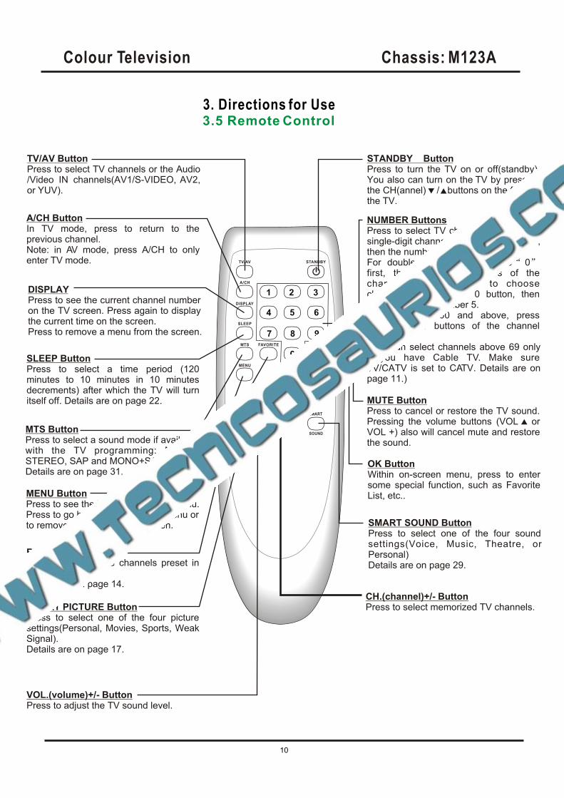
3. Directions for Use3.5 Remote Control
STANDBY ButtonPress to turn the TV on or off(standby). You also can turn on the TV by pressing the CH(annel) / buttons on the front of the TV.
SLEEP ButtonPress to select a time period (120 minutes to 10 minutes in 10 minutes decrements) after which the TV will turn itself off. Details are on page 22.
SMART PICTURE ButtonPress to select one of the four picture settings(Personal, Movies, Sports, Weak Signal).Details are on page 17.
MENU ButtonPress to see the TV s on-screen menu.Press to go back to the previous menu or to remove a menu from the screen.
VOL.(volume)+/- ButtonPress to adjust the TV sound level.
DISPLAYPress to see the current channel number on the TV screen. Press again to display the current time on the screen.Press to remove a menu from the screen.
MUTE ButtonPress to cancel or restore the TV sound. Pressing the volume buttons (VOL or VOL +) also will cancel mute and restore the sound.
MTS ButtonPress to select a sound mode if available with the TV programming: MONO, STEREO, SAP and MONO+SAP.Details are on page 31.
TV/AV ButtonPress to select TV channels or the Audio /Video IN channels(AV1/S-VIDEO, AV2,or YUV).
CH.(channel)+/- ButtonPress to select memorized TV channels.
NUMBER ButtonsPress to select TV channels directly. For single-digit channels, press two 0 first,then the number of the channel.For double-digit channels, press
For channels 100 and above, pressthree number buttons of the channel directly.(You can select channels above 69 only if you have Cable TV. Make sure TV/CATV is set to CATV. Details are on page 11.)
0first, then the two numbers of the channel. For example, to choose channel 45, press the 0 button, then Number 4, then Number 5.
SMART SOUND ButtonPress to select one of the four sound settings(Voice, Music, Theatre, or Personal)Details are on page 29.
A/CH ButtonIn TV mode, press to return to the previous channel.Note: in AV mode, press A/CH to only enter TV mode.
OK ButtonWithin on-screen menu, press to enter some special function, such as Favorite List, etc..
FAVORITE ButtonPress to browse the channels preset in Favorite List.Details are on page 14.
Colour Television Chassis: M123A
10
3. Directions for Use3.6 Language
Language
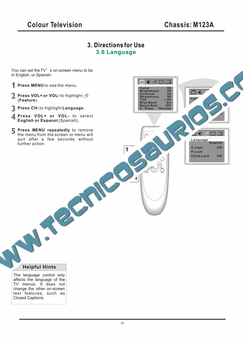
You can set the TV s on-screen menu to be in English, or Spanish.
Press MENU to see the menu.
Press VOL+ or VOL- to highlight(Feature).
Press CH- to highlight Language.
Press VOL+ or VOL- to se lectEnglish or Espanol (Spanish).
Press M NU repeatedly to removethe menu from the screen or menu willquit after a few seconds withoutfurther action.
E
The language control only affects the language of the TV menus. It does not change the other on-screen text features, such as Closed Captions.
Helpful Hints
P.Lock
Child Lock
English
Off
C.Capt Off
Language
BrightnessContrast
TintBlue BackNoise Red.C. Temp
5050
00OnOff
Normal
Sharpness 50
Color 50
EnglishLanguage
P.Lock
Child Lock Off
C.Capt Off,
Colour Television Chassis: M123A
11
3. Directions for Use3.7 TV/Cable TV (CATV)
BrightnessContrast
TintBlue BackNoise Red.C. Temp
5050
50OnOff
Normal
Sharpness 50
Color 50
Add/Erase
Fine 0
F a v o r i t e l i s t
Add2Channel
Manual Up
TVTV/CATV
Auto search
Add/Erase
Fine 0
F a v o r i t e l i s t
Add2Channel
Manual Up
TVTV/CATV
Auto search
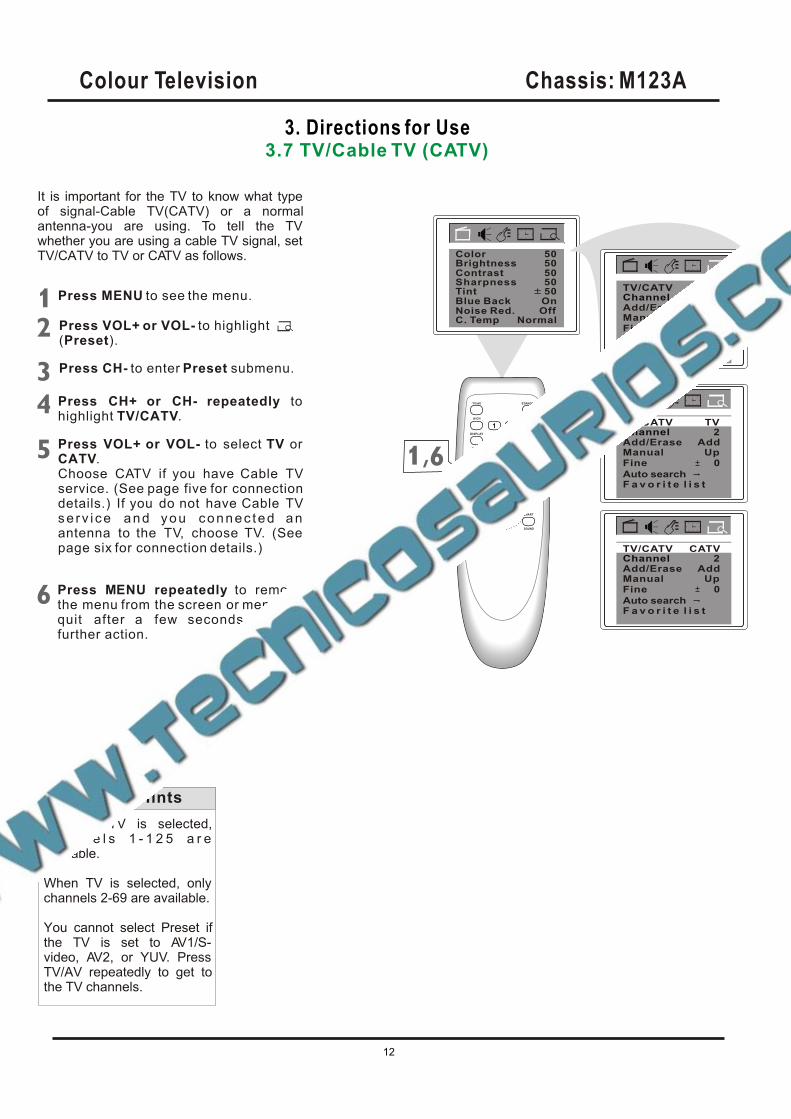
It is important for the TV to know what type of signal-Cable TV(CATV) or a normal antenna-you are using. To tell the TV whether you are using a cable TV signal, set TV/CATV to TV or CATV as follows.
Press MENU to see the menu.
Press CH+ or CH- repeatedly tohighlight TV/CATV.
Press VOL+ or VOL- to select TV orCATV.Choose CATV if you have Cable TVservice. (See page five for connectiondetails.) If you do not have Cable TVse rv i ce and you connec ted an antenna to the TV, choose TV. (Seepage six for connection details.)
Add/Erase
Fine 0
F a v o r i t e l i s t
Add2Channel
Manual Up
CATVTV/CATV
Auto search
When CATV is selected, c h a n n e l s 1 - 1 2 5 a r e available.
When TV is selected, only channels 2-69 are available.
You cannot select Preset if the TV is set to AV1/S-video, AV2, or YUV. Press TV/AV repeatedly to get to the TV channels.
Helpful Hints
Press VOL+ or VOL- to highlight(Preset).
Press CH- to enter Preset submenu.
Press M NU repeatedly to removethe menu from the screen or menu willquit after a few seconds withoutfurther action.
E
,
Colour Television Chassis: M123A
12
3. Directions for Use3.8 Auto Search (Setting TV Channels)
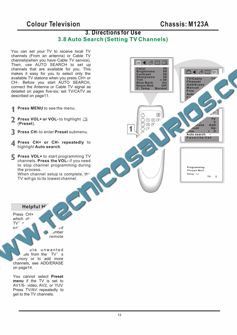
You can set your TV to receive local TV channels (From an antenna) or Cable TV channels(when you have Cable TV service). Then, use AUTO SEARCH to set up channels that are available for you. This makes it easy for you to select only the available TV stations when you press CH+ or CH-. Before you start AUTO SEARCH, connect the Antenna or Cable TV signal as detailed on pages five-six; set TV/CATV as described on page11.
Add/Erase
Fine 0
F a v o r i t e l i s t
Add2Channel
Manual Up
TVTV/Cable
Auto search
Add/Erase
Fine 0
F a v o r i t e l i s t
Add2Channel
Manual Up
TVTV/CATV
Press MENU to see the menu.
Press CH+ or CH- repeatedly tohighlight Auto search.
Press VOL+ or VOL- to highlight(Preset).
Press CH- to enter Preset submenu.
Press VOL+ to start programming TVchannels. Press the VOL- if you need to stop channel programming during the process.When channel setup is complete, the TV will go to its lowest channel.
Programming
P l e a s e Wa i t
TV 2
Press CH+ or CH- to see which channels are in the TV s memory. You can still se lec t non-memor ized channels using the Number buttons on the remote control.
To d e l e t e u n w a n t e d channels from the
You cannot select Presetmenu if the TV is set to AV1/S- video, AV2, or YUV.Press TV/AV repeatedly to get to the TV channels.
TV smemory or to add more channels, see ADD/ERASE on page14.
Helpful Hints
Auto search
S t o p
BrightnessContrast
TintBlue BackNoise Red.C. Temp
5050
50OnOff
Normal
Sharpness 50
Color 50
Colour Television Chassis: M123A
13
3. Directions for Use3.9 Manual Channel Tunning/Fine Tuning
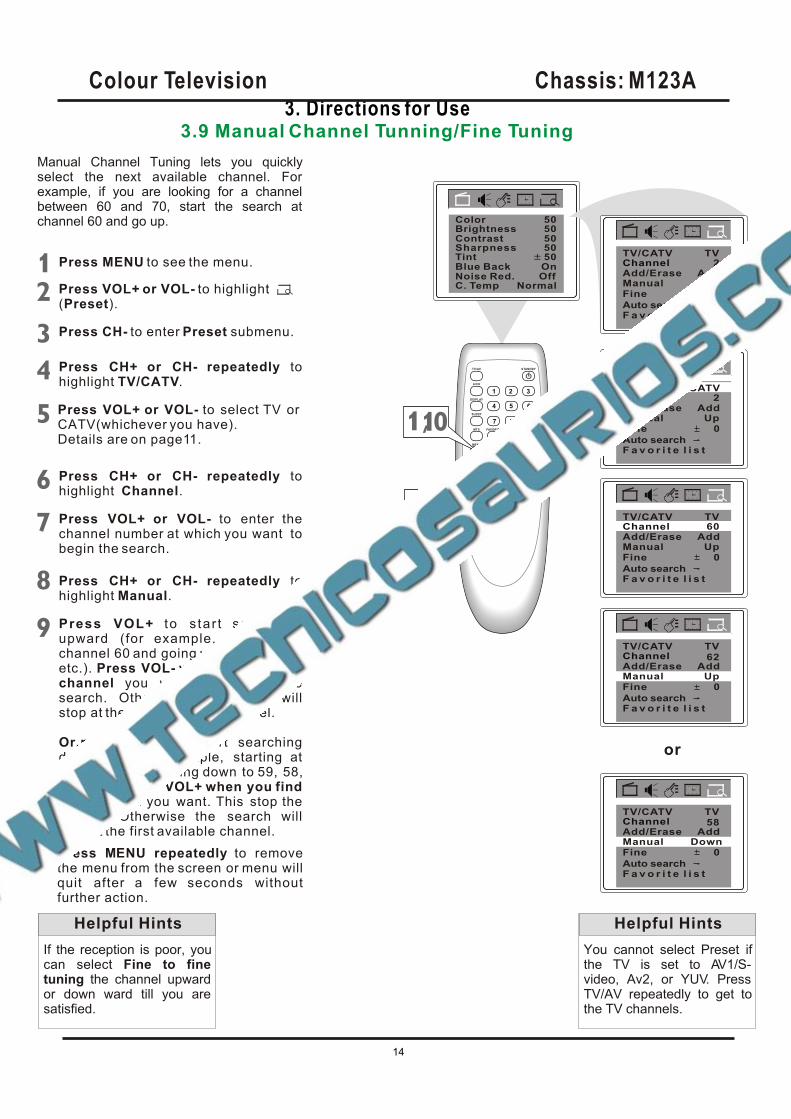
Manual Channel Tuning lets you quickly select the next available channel. For example, if you are looking for a channel between 60 and 70, start the search at channel 60 and go up.
Press MENU to see the menu.
Press CH+ or CH- repeatedly tohighlight Manual.
Press VOL+ to s tar t search ing upward (for example, start ing at channel 60 and going up to 61, 62, 63, etc.). Press VOL- when you find thechannel you want. This stop the search. Otherwise the search will stop at the first available channel.
Or,press VOL- to start searching downward (for example, starting at channel 60 and going down to 59, 58,57, etc.). Press VOL+ when you find the channel you want. This stop the search. Otherwise the search will stop at the first available channel.
BrightnessContrast
TintBlue BackNoise Red.C. Temp
5050
50OnOff
Normal
Sharpness 50
Color 50
Add/Erase
Fine 0
F a v o r i t e l i s t
Add2Channel
Manual Up
TVTV/CATV
Auto search
Add/Erase
Fine 0
F a v o r i t e l i s t
Add
TVTV/CATV
Auto search
Manual Up
Add/Erase
Fine 0
F a v o r i t e l i s t
Add2Channel
Manual Up
CATVTV/CATV
Auto search
Add/Erase
Fine 0
F a v o r i t e l i s t
AddChannel
TVTV/CATV
Auto search
Manual Up
Add/Erase
Fine 0
F a v o r i t e l i s t
AddChannel
TVTV/CATV
Auto search
Manual Down
60Channel
62
58
Press CH+ or CH- repeatedly tohighlight TV/CATV.
Press VOL+ or VOL- to select TV orCATV(whichever you have).Details are on page11.
Press CH+ or CH- repeatedly tohighlight Channel.
Press VOL+ or VOL- to enter the channel number at which you want to begin the search.
If the reception is poor, you can select Fine to fine tuning the channel upward or down ward till you are satisfied.
Helpful Hints
Press VOL+ or VOL- to highlight(Preset).
Press CH- to enter Preset submenu.
Press M NU repeatedly to removethe menu from the screen or menu willquit after a few seconds withoutfurther action.
E
,
or
You cannot select Preset if the TV is set to AV1/S-video, Av2, or YUV. Press TV/AV repeatedly to get to the TV channels.
Helpful Hints
Colour Television Chassis: M123A
14
3. Directions for Use3.10 Favorite Channel Setting
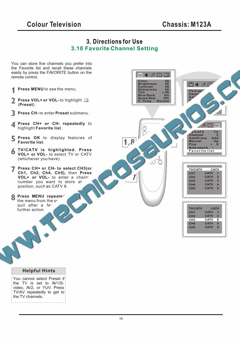
You can store five channels you prefer into the Favorite list and recall these channels easily by press the FAVORITE button on the remote control.
You cannot select Preset if the TV is set to AV1/S-video, AV2, or YUV. Press TV/AV repeatedly to get to the TV channels.
Helpful Hints
Press MENU to see the menu.
Press CH+ or CH- repeatedly tohighlight Favorite list.
Press VOL+ or VOL- to highlight(Preset).
Press CH- to enter Preset submenu.
Press OK to display features ofFavorite list.
Press M NU repeatedly to removethe menu from the screen or menu willquit after a few seconds withoutfurther action.
E
Add/Erase
Fine 0
F a v o r i t e l i s t
Add2Channel
Manual Up
TVTV/Cable
Auto search
Add/Erase
Fine 0
Add2Channel
Manual Up
TVTV/CATV
Auto search
,
BrightnessContrast
TintBlue BackNoise Red.C. Temp
5050
50OnOff
Normal
Sharpness 50
Color 50
F a v o r i t e l i s t
TV/CATV
CH1
CH2
CH3
CH4
CH5
CATV
CATV
CATV
CATV
CATV
CATV
1
2
3
4
5
TV/CATV is highlighted. Press VOL+ or VOL- to select TV or CATV(whichever you have).
TV/CATV
CH1
CH2
CH3
CH4
CH5
CATV
CATV
CATV
CATV
CATV
CATV
1
2
8
4
5
Press CH+ or CH- to select CH3(or Ch1, Ch2, Ch4, Ch5), then PressVOL+ or VOL- to enter a channelnumber you want to store at this position, such as CATV 8.
Colour Television Chassis: M123A
15
3. Directions for Use3.11 Adding or Erasing Channels
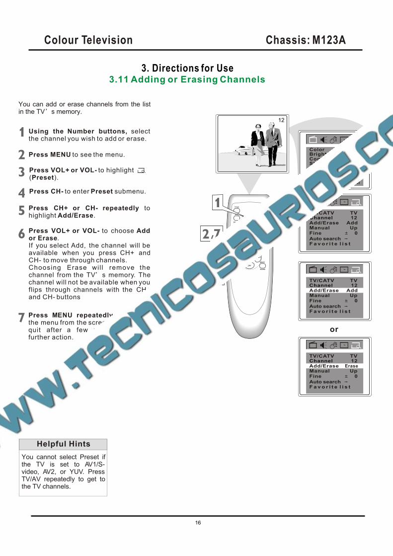
You can add or erase channels from the list in the TV s memory.
Press MENU to see the menu.
Fine 0
F a v o r i t e l i s t
TVTV/CATV
Auto search
Manual Up
12Channel
Press CH+ or CH- repeatedly tohighlight Add/Erase.
Press VOL+ or VOL- to choose Addor Erase.If you select Add, the channel will be available when you press CH+ andCH- to move through channels.Choosing Erase wi l l remove the channel from the TV s memory. Thechannel will not be available when you flips through channels with the CH+and CH- buttons
You cannot select Preset if the TV is set to AV1/S-video, AV2, or YUV. Press TV/AV repeatedly to get to the TV channels.
Helpful Hints
Add/Erase
Fine 0
F a v o r i t e l i s t
Add12Channel
Manual Up
TVTV/CATV
Auto search
BrightnessContrast
TintBlue BackNoise Red.C. Temp
5050
50OnOff
Normal
Sharpness 50
Color 50
Add/Erase Add
Fine 0
F a v o r i t e l i s t
TVTV/CATV
Auto search
Manual Up
12ChannelAdd/Erase Erase
Using the Number buttons, selectthe channel you wish to add or erase.
12
Press M NU repeatedly to removethe menu from the screen or menu willquit after a few seconds withoutfurther action.
E
Press VOL+ or VOL- to highlight(Preset).
Press CH- to enter Preset submenu.
or
,
Colour Television Chassis: M123A
16
3. Directions for Use3.12 Picture Adjustmentt
BrightnessContrast
TintBlue BackNoise Red.C. Temp
5050
00OnOff
Normal
Sharpness 50
Color 50
BrightnessContrast
TintBlue BackNoise Red.C. Temp
5050
00OnOff
Normal
Sharpness 50
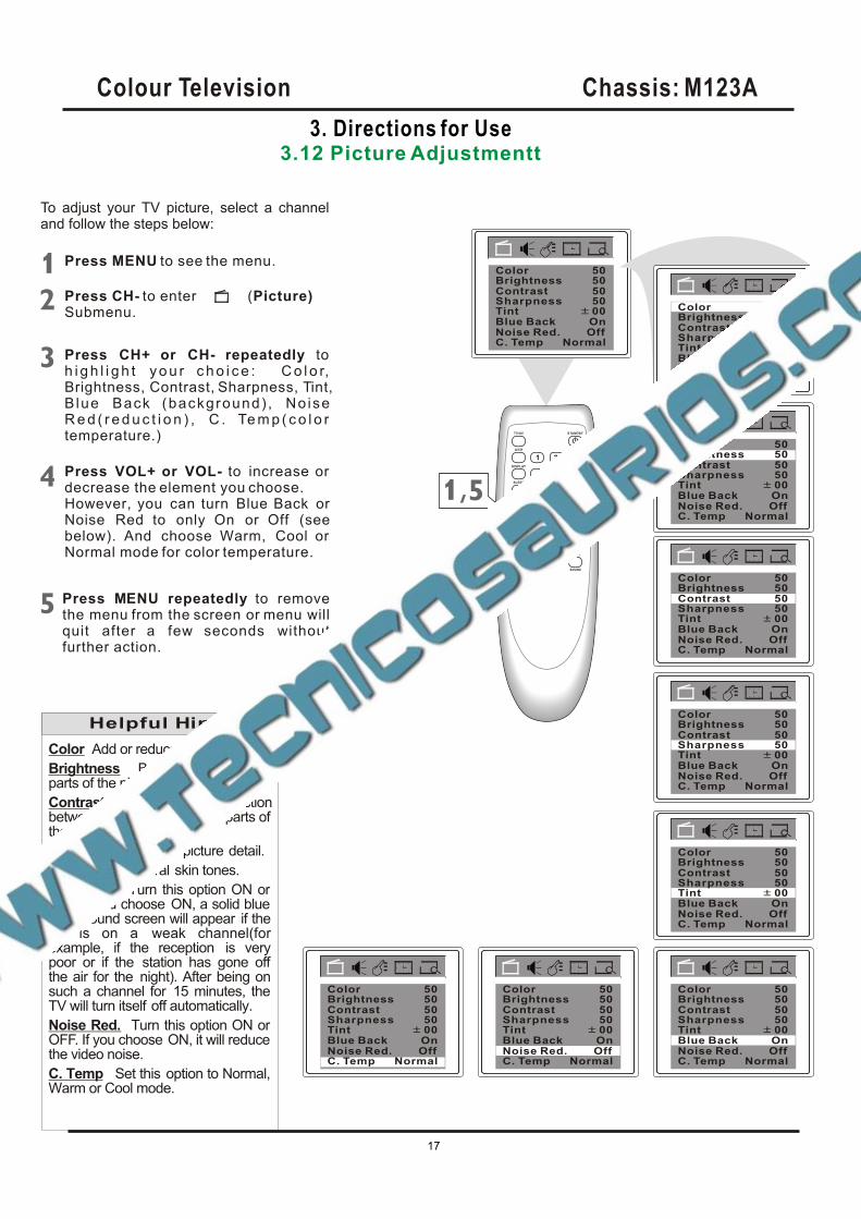
To adjust your TV picture, select a channel and follow the steps below:
Press MENU to see the menu.
Press CH- to enter (Picture)Submenu.
Press CH+ or CH- repeatedly toh i g h l i g h t y o u r c h o i c e : C o l o r,Brightness, Contrast, Sharpness, Tint,B lue Back (background) , No iseR e d ( r e d u c t i o n ) , C . Te m p ( c o l o rtemperature.)
Press VOL+ or VOL- to increase or decrease the element you choose.However, you can turn Blue Back orNoise Red to only On or Off (seebelow). And choose Warm, Cool or Normal mode for color temperature.
Color Add or reduce color.Brightness Brighten the darkestparts of the picture.Contrast Adjust the distinction between the black and white parts of the picture.Sharpness Improve picture detail.Tint Obtain natural skin tones.Blue Back Turn this option ON orOFF. If you choose ON, a solid bluebackground screen will appear if the TV is on a weak channel(for example, if the reception is very poor or if the station has gone off the air for the night). After being on such a channel for 15 minutes, the TV will turn itself off automatically.Noise Red. Turn this option ON orOFF. If you choose ON, it will reducethe video noise.C. Temp Set this option to Normal, Warm or Cool mode.
Helpful Hints
Color 50
Color 50Brightness 50Contrast
TintBlue BackNoise Red.C. Temp
50
00OnOff
Normal
Sharpness 50
Color 50Brightness 50Contrast
TintBlue BackNoise Red.C. Temp
50
00OnOff
Normal
Sharpness 50
Color 50Brightness 50Contrast
TintBlue BackNoise Red.C. Temp
50
00OnOff
Normal
Sharpness 50
Color 50Brightness 50Contrast
TintBlue BackNoise Red.C. Temp
50
00OnOff
Normal
Sharpness 50
Color 50Brightness 50Contrast
TintBlue BackNoise Red.C. Temp
50
00OnOff
Normal
Sharpness 50
Color 50Brightness 50Contrast
TintBlue BackNoise Red.C. Temp
50
00OnOff
Normal
Sharpness 50
Color 50Brightness 50Contrast
TintBlue BackNoise Red.C. Temp
50
00OnOff
Normal
Sharpness 50
Press M NU repeatedly to removethe menu from the screen or menu willquit after a few seconds withoutfurther action.
E
,
Colour Television Chassis: M123A
17
3. Directions for Use3.13 Smart Picture
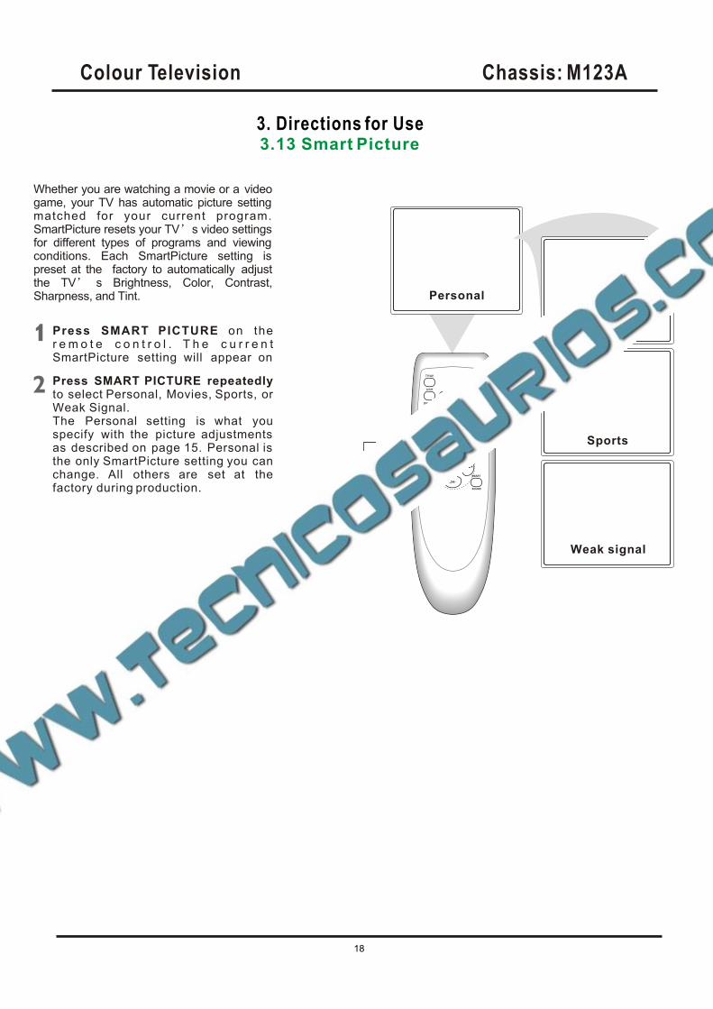
Whether you are watching a movie or a video game, your TV has automatic picture setting matched for your current program. SmartPicture resets your TV s video settings for different types of programs and viewing conditions. Each SmartPicture setting is preset at the factory to automatically adjust the TV s Brightness, Color, Contrast, Sharpness, and Tint.
Press SMART PICTURE on ther e m o t e c o n t r o l . T h e c u r r e n tSmartPicture setting will appear on
Press SMART PICTURE repeatedlyto select Personal, Movies, Sports, orWeak Signal.The Personal setting is what youspecify with the picture adjustments as described on page 15. Personal is the only SmartPicture setting you canchange. All others are set at thefactory during production.
Personal
Movies
Sports
Weak signal
,
Colour Television Chassis: M123A
18
3. Directions for Use3.14 Colck
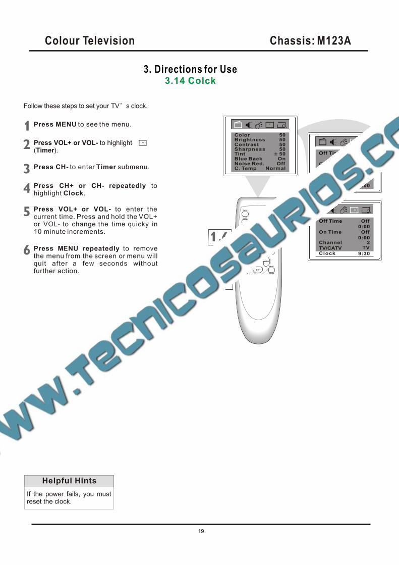
Follow these steps to set your TV s clock.
Press MENU to see the menu.
Press VOL+ or VOL- to highlight(Timer).
Press CH- to enter submenu.Timer
Press CH+ or CH- repeatedly tohighlight Clock.
Press VOL+ or VOL- to enter the current time. Press and hold the VOL+ or VOL- to change the time quicky in10 minute increments.
If the power fails, you must reset the clock.
Helpful Hints
Press M NU repeatedly to removethe menu from the screen or menu willquit after a few seconds withoutfurther action.
E
,
BrightnessContrast
TintBlue BackNoise Red.C. Temp
5050
50OnOff
Normal
Sharpness 50
Color 50
On Time
Channel
TV/CATV
OffOff Time
0:00
2
Off
0:00
TV
Clock 0:00
On Time
Channel
TV/CATV
OffOff Time
0:00
2
Off
0:00
TV
Clock 9:30
Colour Television Chassis: M123A
19
3. Directions for Use3.15 On Timer
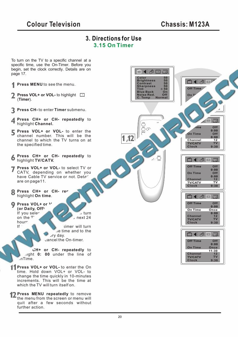
To turn on the TV to a specific channel at a specific time, use the On-Timer. Before you begin, set the clock correctly. Details are on page 17.
Press MENU to see the menu.
Press CH- to enter submenu.Timer
Press CH+ or CH- repeatedly tohighlight On time.
Press VOL+ or VOL- to select Once(or Daily, Off).If you select Once, the timer will turnon the TV one time within the next 24 hours only.If you select Daily, the timer will turn on the TV at the same time and to thesame channel every day.Choose Off to cancel the On-timer.
Press CH+ or CH- repeatedly tohighlight 0: 00 under the line ofOnTime.
Press VOL+ or VOL- to enter the Ontime. Hold down VOL+ or VOL- to change the time quickly in 10-minutesincrements. This will be the time at which the TV will turn itself on.
Press CH+ or CH- repeatedly tohighlight Channel.
Press VOL+ or VOL- to enter the channel number. This will be the channel to which the TV turns on atthe specified time.
Press CH+ or CH- repeatedly tohighlight TV/CATV.
Press VOL+ or VOL- to select TV orCATV, depending on whether you have Cable TV service or not. Details are on page11.
,
BrightnessContrast
TintBlue BackNoise Red.C. Temp
5050
50OnOff
Normal
Sharpness 50
Color 50
On Time
Channel
TV/CATV
OffOff Time
0:00
2
Off
0:00
TV
Clock 9:30
On Time
TV/CATV
OffOff Time
0:00
Off
0:00
TV
Clock 9:30
Press VOL+ or VOL- to highlight(Timer).
Channel 12
On Time
OffOff Time
0:00
Off
0:00
Clock 9:30
Channel 12
TV/CATV TV
OffOff Time
0:00
0:00
Clock 9:30
Channel 12
TV/CATV TV
On Time Once
Press M NU repeatedly to removethe menu from the screen or menu willquit after a few seconds withoutfurther action.
E
OffOff Time
0:00
Clock 9:30
Channel 12
TV/CATV TV
On Time Once
11:30
Colour Television Chassis: M123A
20
3. Directions for Use3.16 OFF Timer
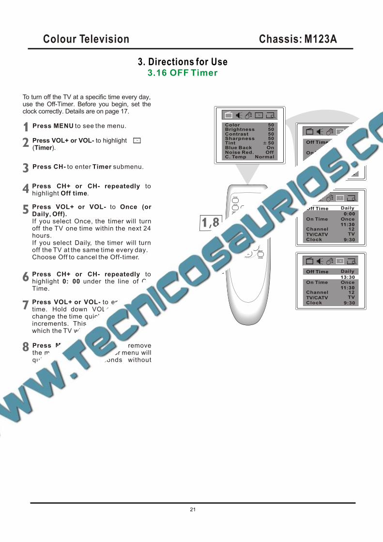
To turn off the TV at a specific time every day, use the Off-Timer. Before you begin, set the clock correctly. Details are on page 17.
Press MENU to see the menu.
Press CH- to enter submenu.Timer
Press CH+ or CH- repeatedly tohighlight Off time.
Press VOL+ or VOL- to
If you select Once, the timer will turnoff the TV one time within the next 24 hours.If you select Daily, the timer will turn off the TV at the same time every day.Choose Off to cancel the Off-timer.
Once (orDaily, Off).
Press CH+ or CH- repeatedly tohighlight 0: 00 under the line of Off Time.
Press VOL+ or VOL- to enter the Offtime. Hold down VOL+ or VOL- to change the time quickly in 10-minutesincrements. This will be the time at which the TV will turn itself off.
Press VOL+ or VOL- to highlight(Timer).
,
BrightnessContrast
TintBlue BackNoise Red.C. Temp
5050
50OnOff
Normal
Sharpness 50
Color 50
Off Time
Clock 9:30
Channel 12
TV/CATV TV
On Time Once
11:30
0:00
Clock 9:30
Channel 12
TV/CATV TV
On Time Once
11:30
OffOff Time
0:00
Clock 9:30
Channel 12
TV/CATV TV
On Time Once
11:30
Off Time Daily
Daily
13:30
Press M NU repeatedly to removethe menu from the screen or menu willquit after a few seconds withoutfurther action.
E
Colour Television Chassis: M123A
21
3. Directions for Use3.17 Closed Captoins
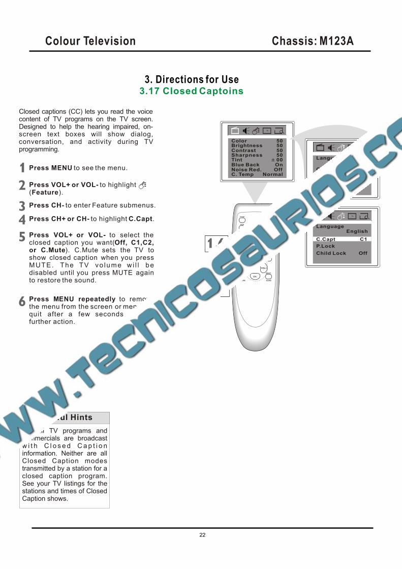
Closed captions (CC) lets you read the voicecontent of TV programs on the TV screen. Designed to help the hearing impaired, on-screen text boxes will show dialog, conversation, and activity during TV programming.
Not all TV programs and commercials are broadcast w i t h C l o s e d C a p t i o n information. Neither are all Closed Caption modes transmitted by a station for a closed caption program. See your TV listings for the stations and times of Closed Caption shows.
Helpful Hints
Press MENU to see the menu.
Press VOL+ or VOL- to highlight(Feature).
Press CH- to enter Feature submenus.
Press VOL+ or VOL- to select the closed caption you want(Off, C1,C2,or C.Mute). C.Mute sets the TV toshow closed caption when you pressMUTE. The TV vo lume w i l l bedisabled until you press MUTE againto restore the sound.
Press M NU repeatedly to removethe menu from the screen or menu willquit after a few seconds withoutfurther action.
E
P.Lock
Child Lock
English
Off
C.Capt Off
Language
BrightnessContrast
TintBlue BackNoise Red.C. Temp
5050
00OnOff
Normal
Sharpness 50
Color 50
EnglishLanguage
P.Lock
Child Lock Off
C.Capt C1,
Press CH+ or CH- to highlight C.Capt.
Colour Television Chassis: M123A
22
3. Directions for Use3.18 Sleep-Timer
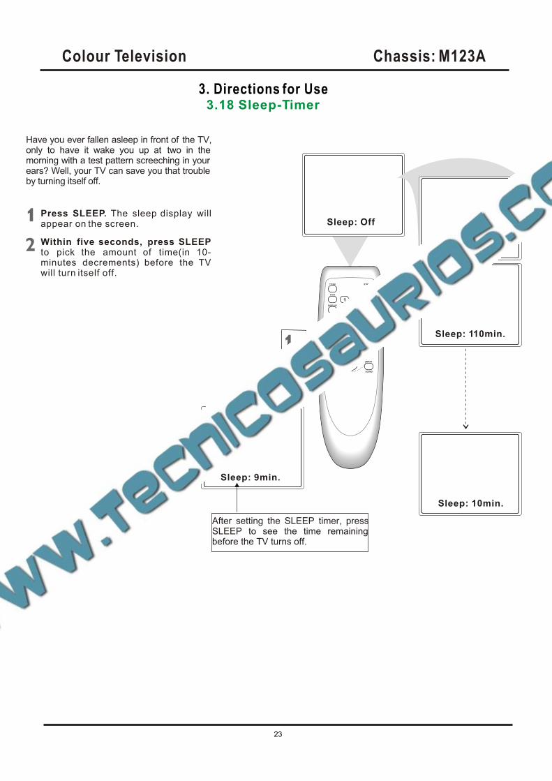
Have you ever fallen asleep in front of the TV, only to have it wake you up at two in the morning with a test pattern screeching in yourears? Well, your TV can save you that trouble by turning itself off.
Press SLEEP. The sleep display willappear on the screen.
Within five seconds, press SLEEP to pick the amount of time(in 10-minutes decrements) before the TV will turn itself off.
Sleep: Off
,
Sleep: 120min.
Sleep: 110min.
Sleep: 10min.
Sleep: 9min.
After setting the SLEEP timer, press SLEEP to see the time remaining before the TV turns off.
Colour Television Chassis: M123A
23
3. Directions for Use3.19 Understanding Parental Lock
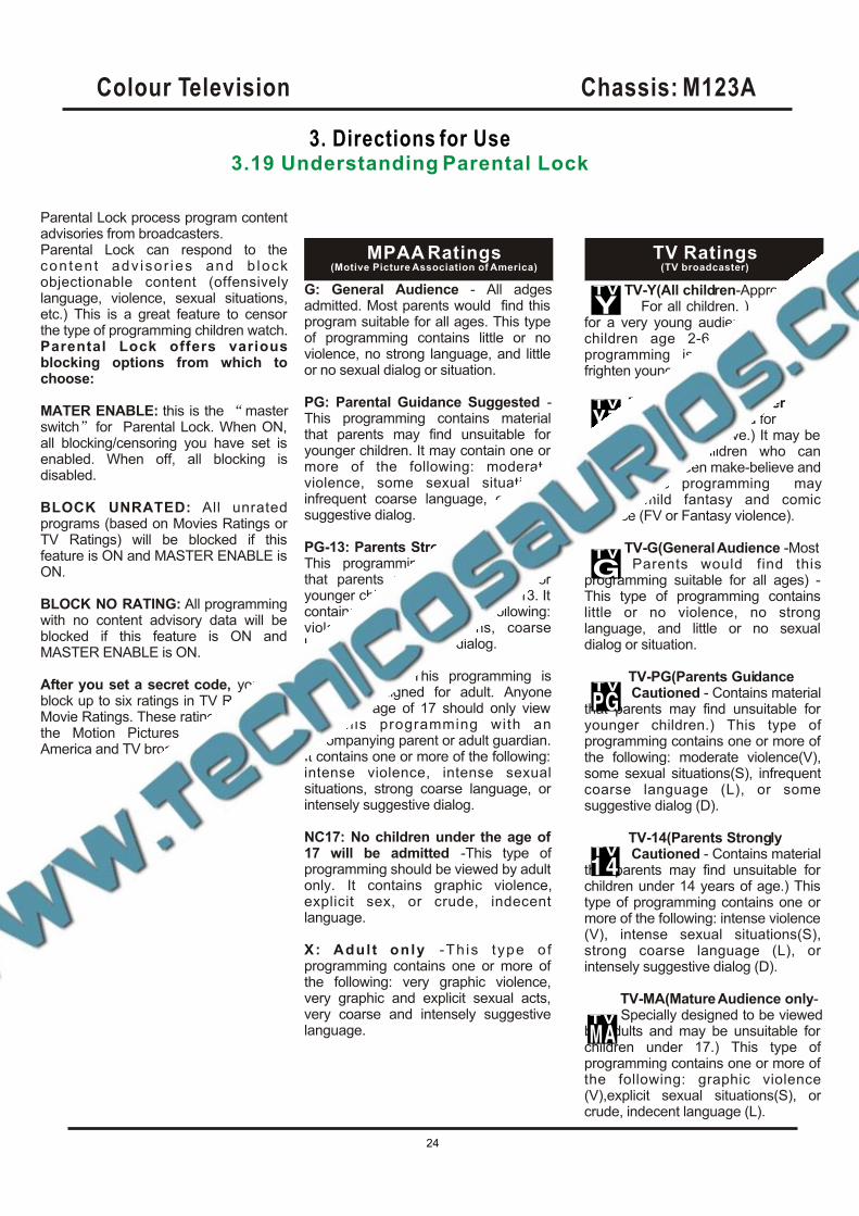
Parental Lock process program content advisories from broadcasters.Parental Lock can respond to the conten t adv isor ies and b lock objectionable content (offensively language, violence, sexual situations, etc.) This is a great feature to censor the type of programming children watch. Parental Lock offers various blocking options from which to choose:
MATER ENABLE: this is the masterswitch for Parental Lock. When ON, all blocking/censoring you have set is enabled. When off, all blocking is disabled.
BLOCK UNRATED: All unrated programs (based on Movies Ratings or TV Ratings) will be blocked if this feature is ON and MASTER ENABLE is ON.
BLOCK NO RATING: All programming with no content advisory data will be blocked if this feature is ON and MASTER ENABLE is ON.
After you set a secret code, you can block up to six ratings in TV Ratings orMovie Ratings. These ratings are set by the Motion Pictures Association of America and TV broadcasters.
G: General Audience - All adges admitted. Most parents would find thisprogram suitable for all ages. This type of programming contains little or no violence, no strong language, and little or no sexual dialog or situation.
PG: Parental Guidance Suggested -This programming contains material that parents may find unsuitable for younger children. It may contain one or more of the following: moderate violence, some sexual situations, infrequent coarse language, or some suggestive dialog.
PG-13: Parents Strongly Cautioned -This programming contains material that parents may find unsuitable for younger children under the age of 13. Itcontains one or more of the following: violence, sexual situations, coarse language, or suggestive dialog.
R: Restricted -This programming is specially designed for adult. Anyoneunder the age of 17 should only viewthe this programming with an accompanying parent or adult guardian. It contains one or more of the following:intense violence, intense sexual situations, strong coarse language, or intensely suggestive dialog.
NC17: No children under the age of 17 will be admitted -This type ofprogramming should be viewed by adult only. It contains graphic violence, explicit sex, or crude, indecent language.
X: Adult only -Th is type o fprogramming contains one or more of the following: very graphic violence, very graphic and explicit sexual acts, very coarse and intensely suggestivelanguage.
MPAA Ratings(Motive Picture Association of America)
TV-Y(All children-Appropriate For all children. ) - Designed for a very young audience, including children age 2-6. This type of programming is not expected to frighten younger children.
TV-Y7(Directed to Older Children - Designed for children age 7 and above.) It may beappropriate for children who can distinguish between make-believe and reality. This programming may include mild fantasy and comic violence (FV or Fantasy violence).
TV-G(General Audience -Most Parents would find this programming suitable for all ages) - This type of programming contains little or no violence, no strong language, and little or no sexual dialog or situation.
TV-PG(Parents Guidance Cautioned - Contains material that parents may find unsuitable for younger children.) This type of programming contains one or more of the following: moderate violence(V), some sexual situations(S), infrequent coarse language (L), or some suggestive dialog (D).
TV-14(Parents Strongly Cautioned - Contains material that parents may find unsuitable for children under 14 years of age.) This type of programming contains one or more of the following: intense violence (V), intense sexual situations(S), strong coarse language (L), or intensely suggestive dialog (D).
TV-MA(Mature Audience only- Specially designed to be viewed by adults and may be unsuitable for children under 17.) This type of programming contains one or more of the following: graphic violence (V),explicit sexual situations(S), or crude, indecent language (L).
TV Ratings(TV broadcaster)
Colour Television Chassis: M123A
24
3. Directions for Use3.20 Parental Lock Secret Code
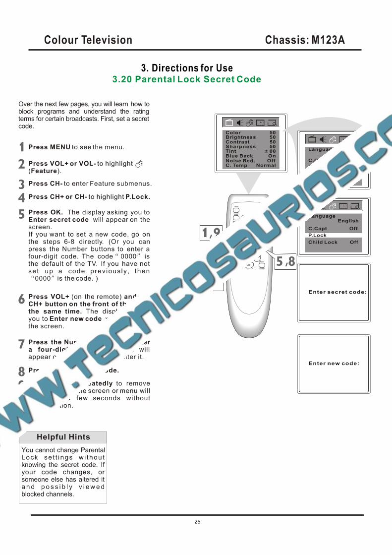
Over the next few pages, you will learn how to block programs and understand the rating terms for certain broadcasts. First, set a secretcode.
You cannot change Parental Lock se t t ings w i thou t knowing the secret code. If your code changes, or someone else has altered it a n d p o s s i b l y v i e w e d blocked channels.
Helpful Hints
P.Lock
Child Lock
English
Off
C.Capt Off
Language
BrightnessContrast
TintBlue BackNoise Red.C. Temp
5050
00OnOff
Normal
Sharpness 50
Color 50
EnglishLanguage
P.Lock
Child Lock Off
C.Capt Off,
Press MENU to see the menu.
Press VOL+ or VOL- to highlight(Feature).
Press CH- to enter Feature submenus.
Press VOL+ (on the remote) and theCH+ button on the front of the TV at the same time. The display asking you to Enter new code will appear on the screen.
Press M NU repeatedly to removethe menu from the screen or menu willquit after a few seconds withoutfurther action.
E
Press CH+ or CH- to highlight P.Lock.
Press OK. The display asking you to Enter secret code will appear on thescreen.If you want to set a new code, go onthe steps 6-8 directly. (Or you canpress the Number buttons to enter a four-digit code. The code 0000 isthe default of the TV. If you have not set up a code prev ious ly , then
0000 is the code. )
Enter secret code:
Enter new code:
Press the Number buttons to entera four-digit code. The code will appear on the screen as you enter it.
Press OK to save the code.
,
,
Colour Television Chassis: M123A
25
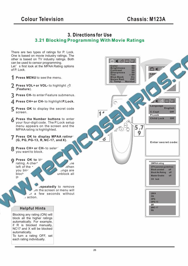
3. Directions for Use3.21 Blocking Programming With Movie Ratings
There are two types of ratings for P. Lock. One is based on movie industry ratings. The other is based on TV industry ratings. Both can be used to censor programming.Let s first look at the MPAA Rating options of P. Lock.
Blocking any rating (ON) will block all the higher ratings automatically. For example, if R is blocked manually, NC17 and X will be blocked automatically.To turn a rating OFF, set each rating individually.
Helpful Hints
Press MENU to see the menu.
Press VOL+ or VOL- to highlight(Feature).
Press CH- to enter Feature submenus.
Press M NU repeatedly to removethe menu from the screen or menu willquit after a few seconds withoutfurther action.
E
Press CH+ or CH- to highlight P.Lock.
Press the Number buttons to enteryour four-digit code. The P.Lock setupmenu appears on the screen and the MPAA rating is highlighted.
Press OK to display MPAA ratings (G, PG, PG-13, R, NC-17, and X).
Press CH+ or CH- to select the ratingyou want to block.
Press OK to block (or unblock) therating. A checkmark will appear to the left of the rating when blocked. When you block a rating, higher ratings are blocked automatically. To unblock all the ratings, select N/A.
P.Lock
Child Lock
English
Off
C.Capt Off
Language
BrightnessContrast
TintBlue BackNoise Red.C. Temp
5050
00OnOff
Normal
Sharpness 50
Color 50
EnglishLanguage
P.Lock
Child Lock Off
C.Capt Off,
Enter secret code:
,
TV parental guidelines
Block unrated off
Block No Rating off
MPAA rating
Master Enable off
CH lock
G
PG-13
N/A
R
NC-17
X
PG
Press OK to display the secret code screen.
Colour Television Chassis: M123A
26
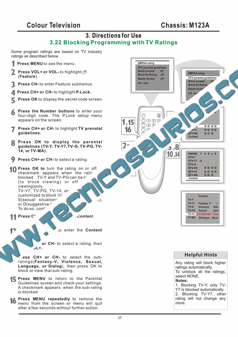
3. Directions for Use3.22 Blocking Programming with TV Ratings
Some program ratings are based on TV industry ratings as described below.
Any rating will block higher ratings automatically. To unblock all the ratings, select NONE.Notes:1. Blocking TV-Y, only TV-Y7 is blocked automatically. 2. Blocking TV-Y7, other rating will not change any more.
Helpful Hints
,
,
TV parental guidelines
Block unrated off
Block No Rating off
MPAA rating
Master Enable off
CH lockBlock unrated off
Block No Rating off
MPAA rating
Master Enable off
CH lock
TV parental guidelines
TV-Y
TV-Y7
TV-G
NONE F V S L D
TV-PG
TV-14
Content
TV-MA
TV-Y7
TV-G
Content
TV-14
TV-MA
Violence
Sexual
Language
Dialogue
---
------
---
TV-Y
Fantasy V ---
TV-PG
TV-Y7
TV-G
Content
TV-14
TV-MA
Violence
Sexual
Language
Dialogue
View
TV-Y
Fantasy V ---
TV-PG View
View
Block
Press MENU to see the menu.
Press VOL+ or VOL- to highlight(Feature).
Press CH- to enter Feature submenus.
Press M NU repeatedly to remove the menu from the screen or menu will quitafter a few seconds without further action.
E
Press CH+ or CH- to highlight P.Lock.
Press the Number buttons to enter your four-digit code. The P.Lock setup menu appears on the screen.
Press OK to d isplay the parenta lguidelines (TV-Y, TV-Y7,TV-G, TV-PG, TV-14, or TV-MA).
Press CH+ or CH- to select a rating.
Press OK to turn the rating on or off. Acheckmark appears when the rating isblocked. TV-Y and TV-PG can be turned on( to b lock v i ew ing ) o r o f f ( t o a l l ow viewing)only.TV-Y7, TV-PG, TV-14, and TV-MA can be customized to block V(violence), F(fantasy), S(sexual situations), L(coarse language),or D(suggestive dialog).To do so, continue with these steps.
Press CH+ or CH- to highlight TV prenatalguidelines.
Press CH+ or CH- to highlight Content.
Press OK button to enter the Contentmenu.
TV-Y
TV-Y7
TV-G
NONE F V S L D
TV-PG
TV-14
Content
TV-MA
Press CH+ or CH- to select a rating, then press VOL+.
Press CH+ or CH- to select the sub-rat ings(Fantasy-V, Violence, Sexual,Language, or Dialog), then press OK to block or view that sub-rating.
Press M NU to return to the Parental Guidelines screen and check your settings.A checkmark appears when the sub-rating is blocked.
E
Press OK to display the secret code screen.
,,
,
Colour Television Chassis: M123A
27
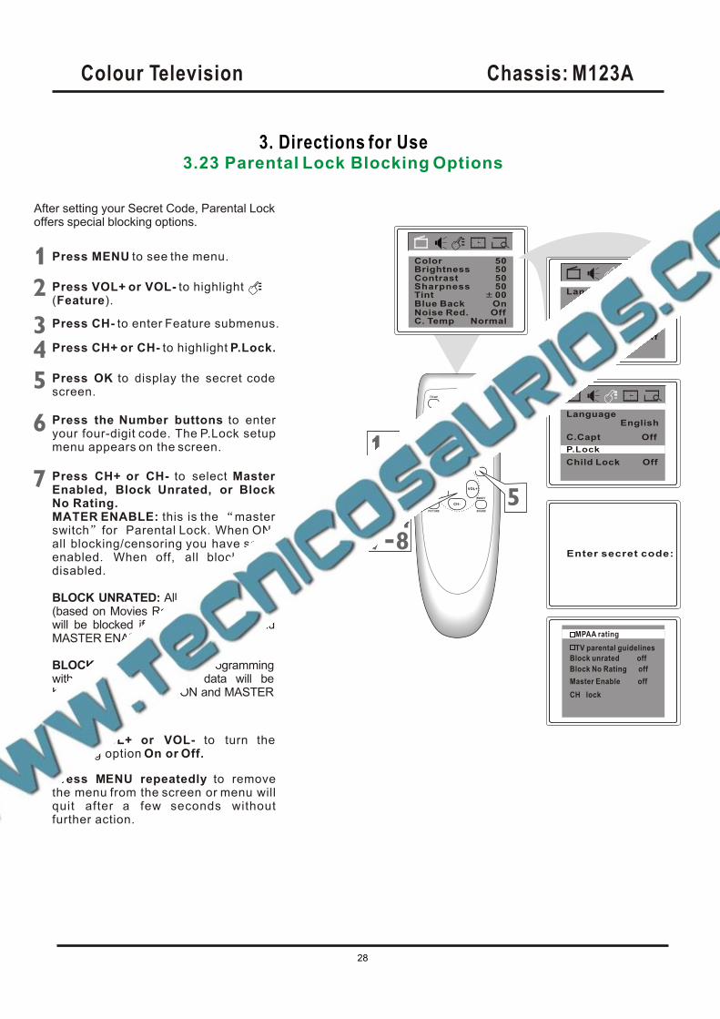
3. Directions for Use3.23 Parental Lock Blocking Options
After setting your Secret Code, Parental Lock offers special blocking options.
Press MENU to see the menu.
Press VOL+ or VOL- to highlight(Feature).
Press CH- to enter Feature submenus.
Press M NU repeatedly to removethe menu from the screen or menu willquit after a few seconds withoutfurther action.
E
Press CH+ or CH- to highlight P.Lock.
Press the Number buttons to enteryour four-digit code. The P.Lock setupmenu appears on the screen.
Press CH+ or CH- to select MasterEnabled, Block Unrated, or Block No Rating.MATER ENABLE: this is the masterswitch for Parental Lock. When ON, all blocking/censoring you have set isenabled. When off, all blocking isdisabled.
BLOCK UNRATED: All unrated programs (based on Movies Ratings or TV Ratings) will be blocked if this feature is ON and MASTER ENABLE is ON.
BLOCK NO RATING: All programming with no content advisory data will be blocked if this feature is ON and MASTERENABLE is ON.
Press VOL+ or VOL- to turn the blocking option On or Off.
P.Lock
Child Lock
English
Off
C.Capt Off
Language
BrightnessContrast
TintBlue BackNoise Red.C. Temp
5050
00OnOff
Normal
Sharpness 50
Color 50
EnglishLanguage
P.Lock
Child Lock Off
C.Capt Off,
Enter secret code:
TV parental guidelines
Block unrated off
Block No Rating off
MPAA rating
Master Enable off
CH lock
Press OK to display the secret code screen.
Colour Television Chassis: M123A
28
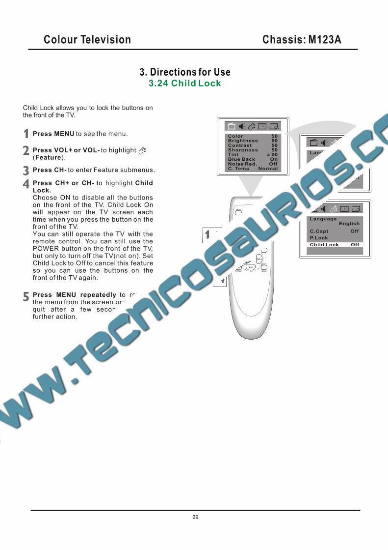
3. Directions for Use3.24 Child Lock
Child Lock allows you to lock the buttons on the front of the TV.
P.Lock
Child Lock
English
Off
C.Capt Off
Language
BrightnessContrast
TintBlue BackNoise Red.C. Temp
5050
00OnOff
Normal
Sharpness 50
Color 50
EnglishLanguage
P.Lock
Child Lock Off
C.Capt Off
Press MENU to see the menu.
Press VOL+ or VOL- to highlight(Feature).
Press CH- to enter Feature submenus.
Press CH+ or CH- to highlight ChildLock.Choose ON to disable all the buttons on the front of the TV. Child Lock Onwill appear on the TV screen each time when you press the button on thefront of the TV.You can still operate the TV with the remote control. You can still use the POWER button on the front of the TV,but only to turn off the TV(not on). Set Child Lock to Off to cancel this featureso you can use the buttons on thefront of the TV again.
Press M NU repeatedly to removethe menu from the screen or menu willquit after a few seconds withoutfurther action.
E
,
Colour Television Chassis: M123A
29
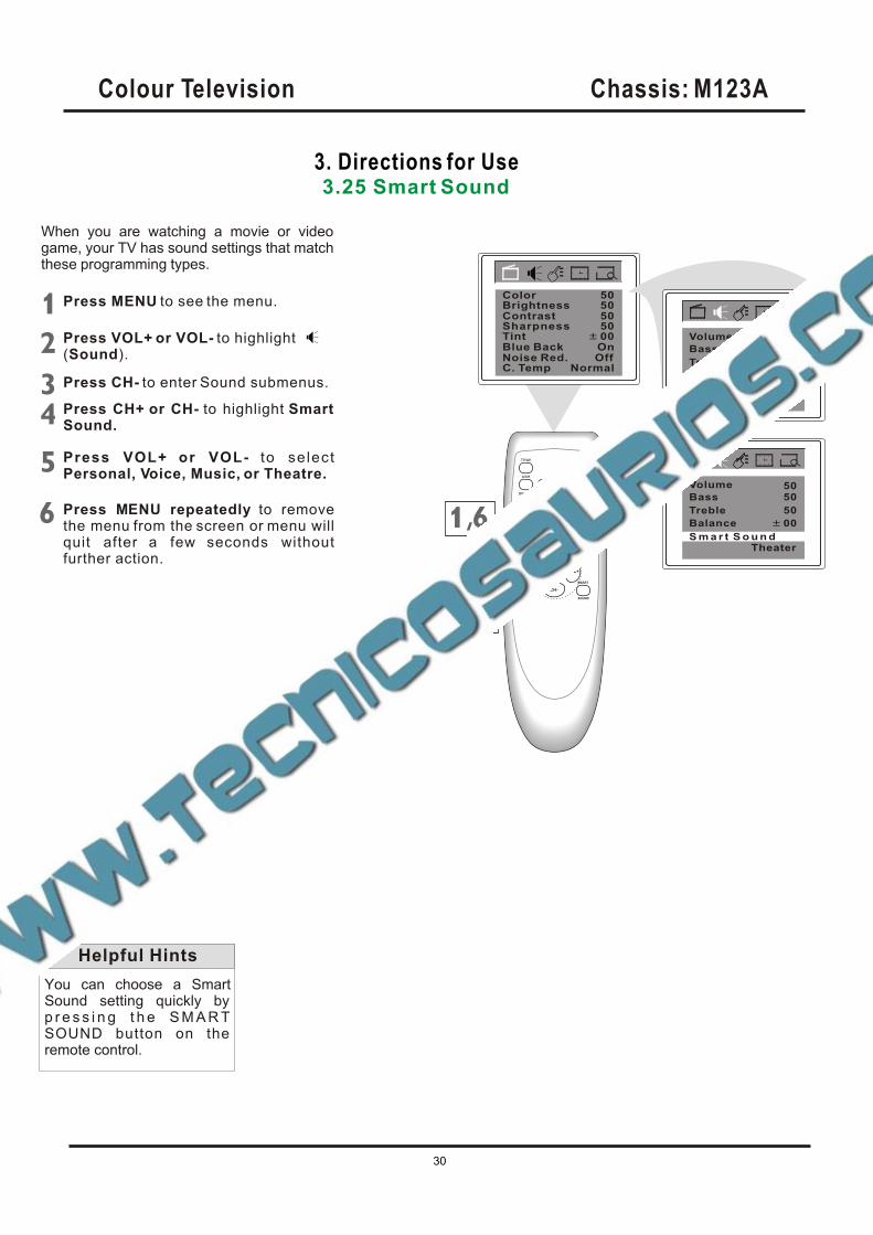
3. Directions for Use3.25 Smart Sound
When you are watching a movie or video game, your TV has sound settings that match these programming types.
You can choose a Smart Sound setting quickly by p r e s s i n g t h e S M A R T SOUND button on the remote control.
Helpful Hints
Press MENU to see the menu.
Press VOL+ or VOL- to highlight(Sound).
Press CH- to enter Sound submenus.
Press CH+ or CH- to highlight SmartSound.
Press VOL+ or VOL- to se lectPersonal, Voice, Music, or Theatre.
Press M NU repeatedly to removethe menu from the screen or menu willquit after a few seconds withoutfurther action.
E
BrightnessContrast
TintBlue BackNoise Red.C. Temp
5050
00OnOff
Normal
Sharpness 50
Color 50
Treble
Balance
S m a r t S o u n d
50
00
Theater
Volume
Bass 5050
Treble
Balance
50
00
Theater
Volume
Bass 5050
S m a r t S o u n d
,
Colour Television Chassis: M123A
30
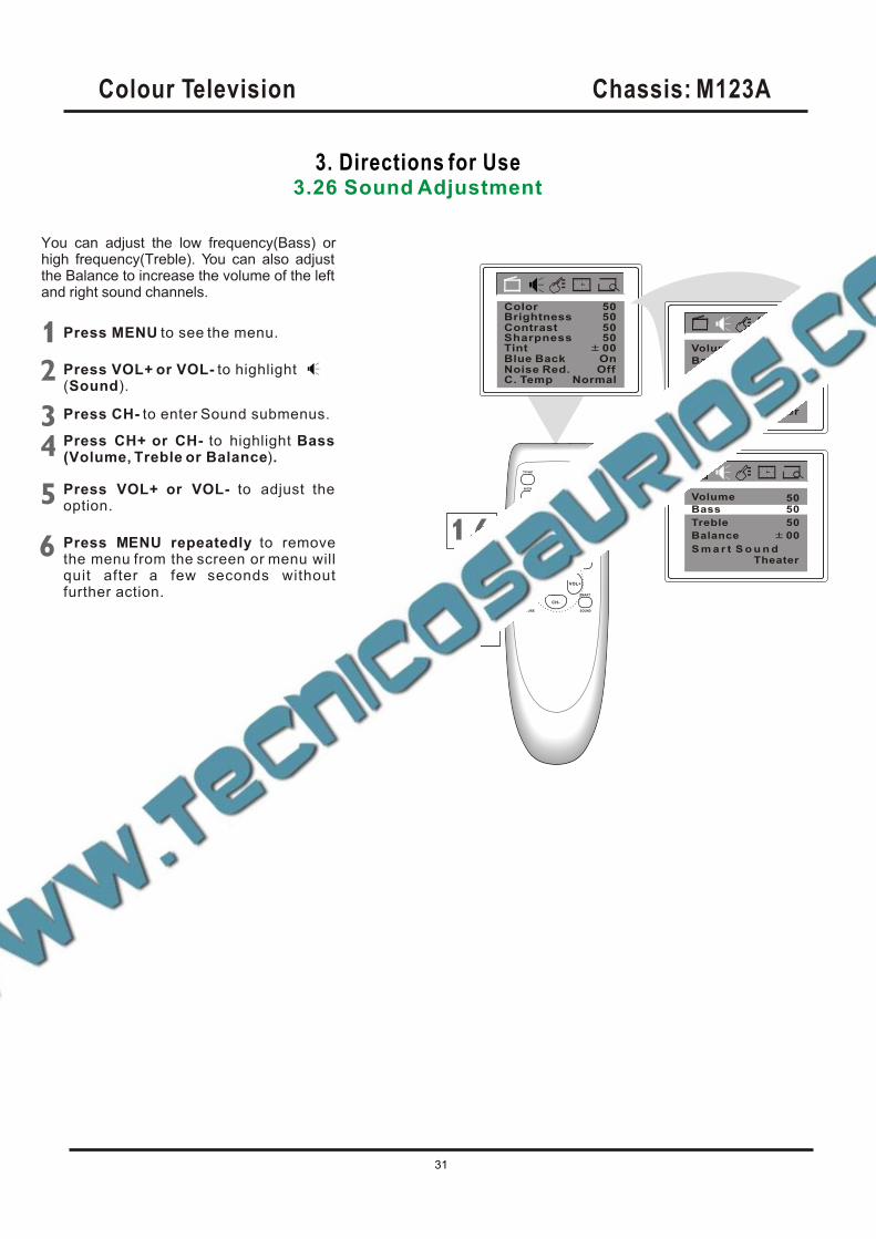
3. Directions for Use3.26 Sound Adjustment
BrightnessContrast
TintBlue BackNoise Red.C. Temp
5050
00OnOff
Normal
Sharpness 50
Color 50
Treble
Balance
S m a r t S o u n d
50
00
Theater
Volume
Bass 5050
Treble
Balance
S m a r t S o u n d
50
00
Theater
Volume
Bass 5050
Press MENU to see the menu.
Press VOL+ or VOL- to highlight(Sound).
Press CH- to enter Sound submenus.
Press CH+ or CH- to highlight Bass(Volume, Treble or Balance).
Press VOL+ or VOL- to adjust the option.
Press M NU repeatedly to removethe menu from the screen or menu willquit after a few seconds withoutfurther action.
E
You can adjust the low frequency(Bass) or high frequency(Treble). You can also adjust the Balance to increase the volume of the left and right sound channels.
,
Colour Television Chassis: M123A
31
3. Directions for Use3.27 Stereo and Second Audio Program
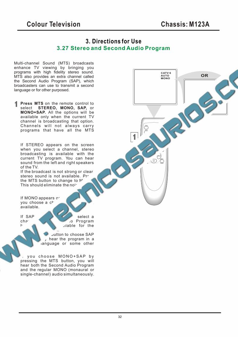
Multi-channel Sound (MTS) broadcasts enhance TV viewing by bringing you programs with high fidelity stereo sound. MTS also provides an extra channel called the Second Audio Program (SAP), which broadcasters can use to transmit a second language or for other purposed.
Press MTS on the remote control to select STEREO, MONO, SAP, or MONO+SAP. All the options will beavailable only when the current TVchannel is broadcasting that option. Channe ls w i l l no t a lways car ry programs that have all the MTS
If STEREO appears on the screenwhen you select a channel, stereobroadcasting is available with the current TV program. You can hear sound from the left and right speakers of the TV.If the broadcast is not strong or clear,stereo sound is not available. Pressthe MTS button to change to MONO. This should eliminate the noise.
If MONO appears on the screen when you choose a channel, Stereo is not available.
If SAP appears when you select a channel , Second Audio Program broadcasting is available for the current TV program.Press the MTS button to choose SAP and you may hear the program in adifferent language or some other
I f y o u c h o o s e M O N O + S A P b y pressing the MTS button, you willhear both the Second Audio Program and the regular MONO (monaural orsingle-channel) audio simultaneously.
CATV 6AUTOMONO
CATV 22AUTOMONOSTEREOSAP
OR
Colour Television Chassis: M123A
32
Colour Television Chassis: M123A
dd
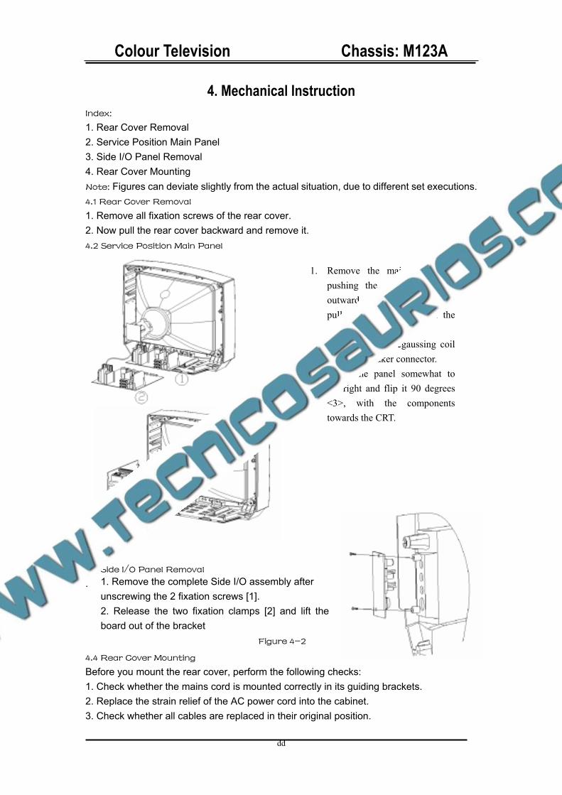
1. Remove the complete Side I/O assembly after unscrewing the 2 fixation screws [1]. 2. Release the two fixation clamps [2] and lift the board out of the bracket
Figure 4-2
4. Mechanical Instruction Index:
1. Rear Cover Removal 2. Service Position Main Panel 3. Side I/O Panel Removal 4. Rear Cover Mounting Note: Figures can deviate slightly from the actual situation, due to different set executions. 4.1 Rear Cover Removal
1. Remove all fixation screws of the rear cover. 2. Now pull the rear cover backward and remove it. 4.2 Service Position Main Panel
4.3 Side I/O Panel Removal
.
4.4 Rear Cover Mounting
Before you mount the rear cover, perform the following checks: 1. Check whether the mains cord is mounted correctly in its guiding brackets. 2. Replace the strain relief of the AC power cord into the cabinet. 3. Check whether all cables are replaced in their original position.
1. Remove the main panel, by pushing the two center clips outward <1>. At the same time pull the panel away from the CRT <2>.
2. Disconnect the degaussing coil and load speaker connector.
3. Move the panel somewhat to the right and flip it 90 degrees <3>, with the components towards the CRT.
Colour Television Chassis: M123A
34
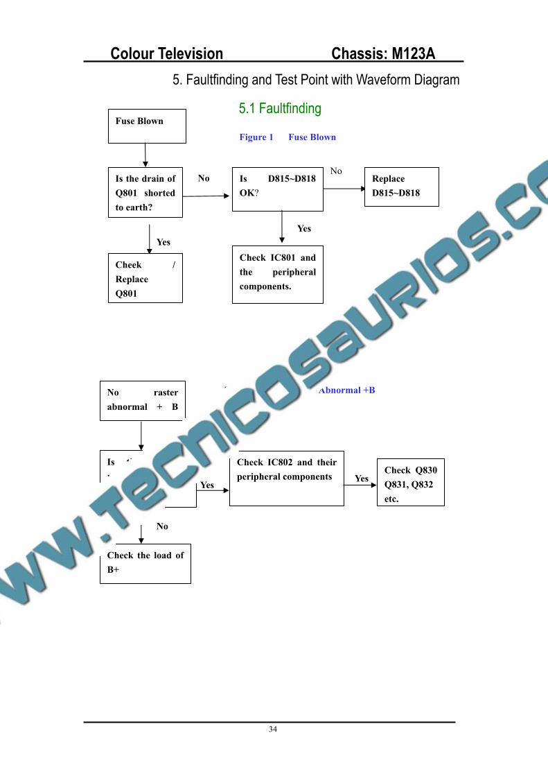
5. Faultfinding and Test Point with Waveform Diagram
5.1 Faultfinding Fuse Blown
Is the drain of Q801 shorted to earth?
Yes
Cheek / ReplaceQ801
Is D815~D818 OK?
Yes
Check IC801 and the peripheral components.
ReplaceD815~D818
No No
Figure 1 Fuse Blown
No raster abnormal + B
Is the + B, resistance to earth ok ?
Check the load of B+
No
Yes
Check IC802 and their peripheral components Yes
Check Q830 Q831, Q832 etc.
Figure2 No Raster Abnormal +B
Colour Television Chassis: M123A
35
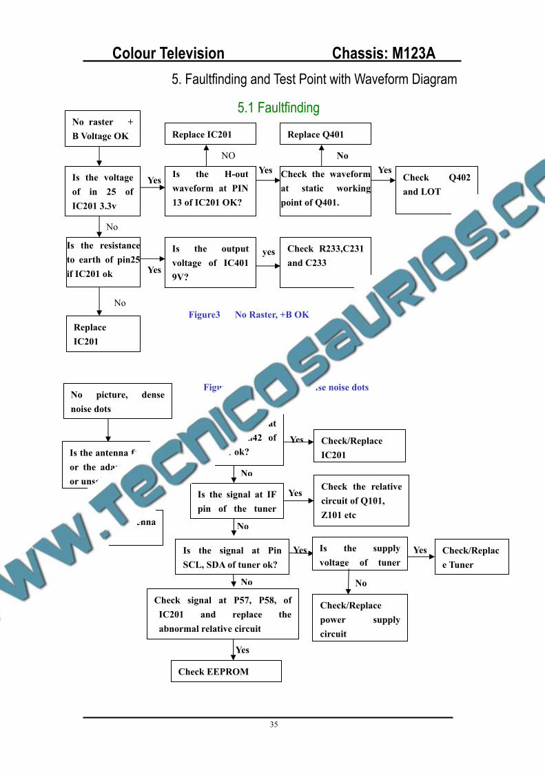
5. Faultfinding and Test Point with Waveform Diagram
5.1 Faultfinding No raster + B Voltage OK
Is the voltage of in 25 of IC201 3.3v
Is the resistance to earth of pin25 if IC201 ok
No
Yes Is the H-out waveform at PIN 13 of IC201 OK?
Yes Check the waveform at static working point of Q401.
Yes Check Q402 and LOT
No
ReplaceIC201
NO
Yes
Replace IC201 Replace Q401
Is the output voltage of IC401 9V?
Check R233,C231 and C233
yes
No Figure3 No Raster, +B OK
No
No
No picture, dense noise dots
Is the antenna feed line or the adapter broken or unsoldered?
Handing the antenna fault
Yes
No
Is the signal at Pin41, Pin42 of IC201 ok?
Is the signal at IF pin of the tuner
Is the signal at Pin SCL, SDA of tuner ok?
No
Check signal at P57, P58, of IC201 and replace the abnormal relative circuit
Yes
Check EEPROM
Yes Check/ReplaceIC201
Yes Is the supply voltage of tuner
No
Check/Replacepower supply circuit
Yes Check/Replace Tuner
YesCheck the relative circuit of Q101, Z101 etc
Figure 4 No Picture dense noise dots
Colour Television Chassis: M123A
36
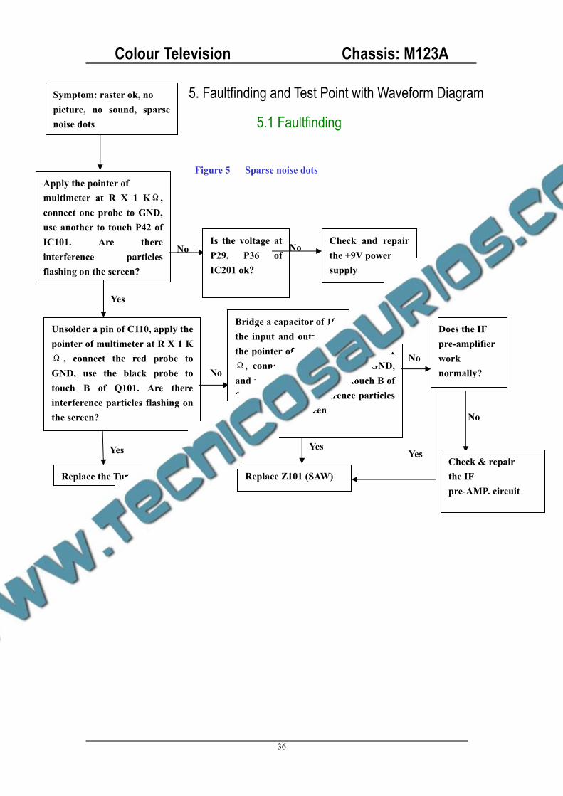
5. Faultfinding and Test Point with Waveform Diagram
5.1 Faultfinding
Yes
Symptom: raster ok, no picture, no sound, sparse noise dots
Apply the pointer of multimeter at R X 1 K ,connect one probe to GND, use another to touch P42 of IC101. Are there interference particles flashing on the screen?
Unsolder a pin of C110, apply the pointer of multimeter at R X 1 K
, connect the red probe to GND, use the black probe to touch B of Q101. Are there interference particles flashing on the screen?
Yes
Replace the Tuner
No Is the voltage at P29, P36 of IC201 ok?
No Check and repair the +9V power supply
No
Bridge a capacitor of 1000pF between the input and output of Z101. Apply the pointer of multimeter at R X 1 K
, connect the red probe to GND, and use the black probe to touch B of Q101 Are there interference particles flashing on the screen
Yes
Replace Z101 (SAW)
Does the IF pre-amplifier work normally?
Yes Check & repair the IF pre-AMP. circuit
No
Figure 5 Sparse noise dots
No
Colour Television Chassis: M123A
37
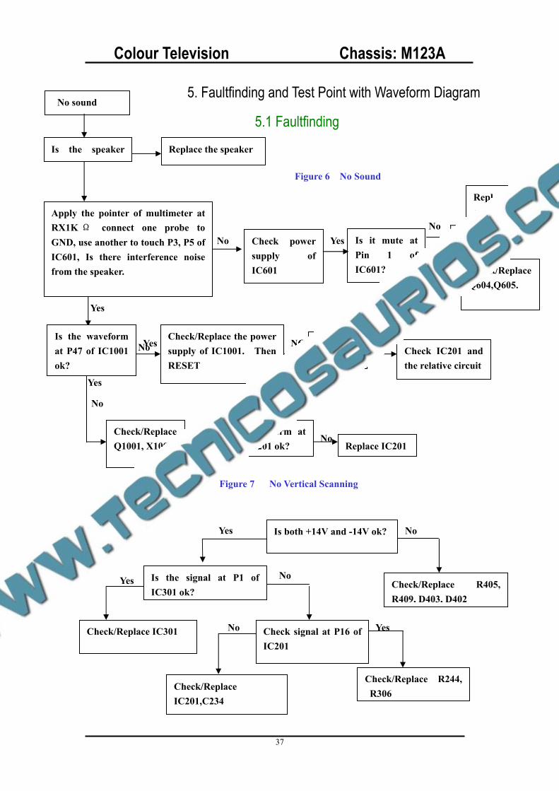
No
Yes
Is it mute at Pin 1 of IC601? Yes
No sound
Is the speaker Replace the speaker
Apply the pointer of multimeter at RX1K connect one probe to GND, use another to touch P3, P5 of IC601, Is there interference noise from the speaker.
No Check power supply of IC601
Yes
Is the waveform at P47 of IC1001 ok?
Yes Check/Replace the power supply of IC1001. Then RESET
NG Is the BUS ok?
Check IC201 and the relative circuit
No
No
Check/ReplaceQ1001, X1002.
NG Is the waveform at P31 of IC201 ok? Replace IC201
No
Yes
Replace IC601
Check/ReplaceQ604,Q605.
No
Figure 6 No Sound
Is both +14V and -14V ok?Yes No
Is the signal at P1 of IC301 ok?
Check/Replace IC301 Check signal at P16 of IC201
No
Check/ReplaceIC201,C234
Yes
Check/Replace R244, R306
Yes
Check/Replace R405, R409, D403, D402
No
Figure 7 No Vertical Scanning
5. Faultfinding and Test Point with Waveform Diagram
5.1 Faultfinding
Colour Television Chassis: M123A
38
Check P25, P49 of IC201 and the relative circuit
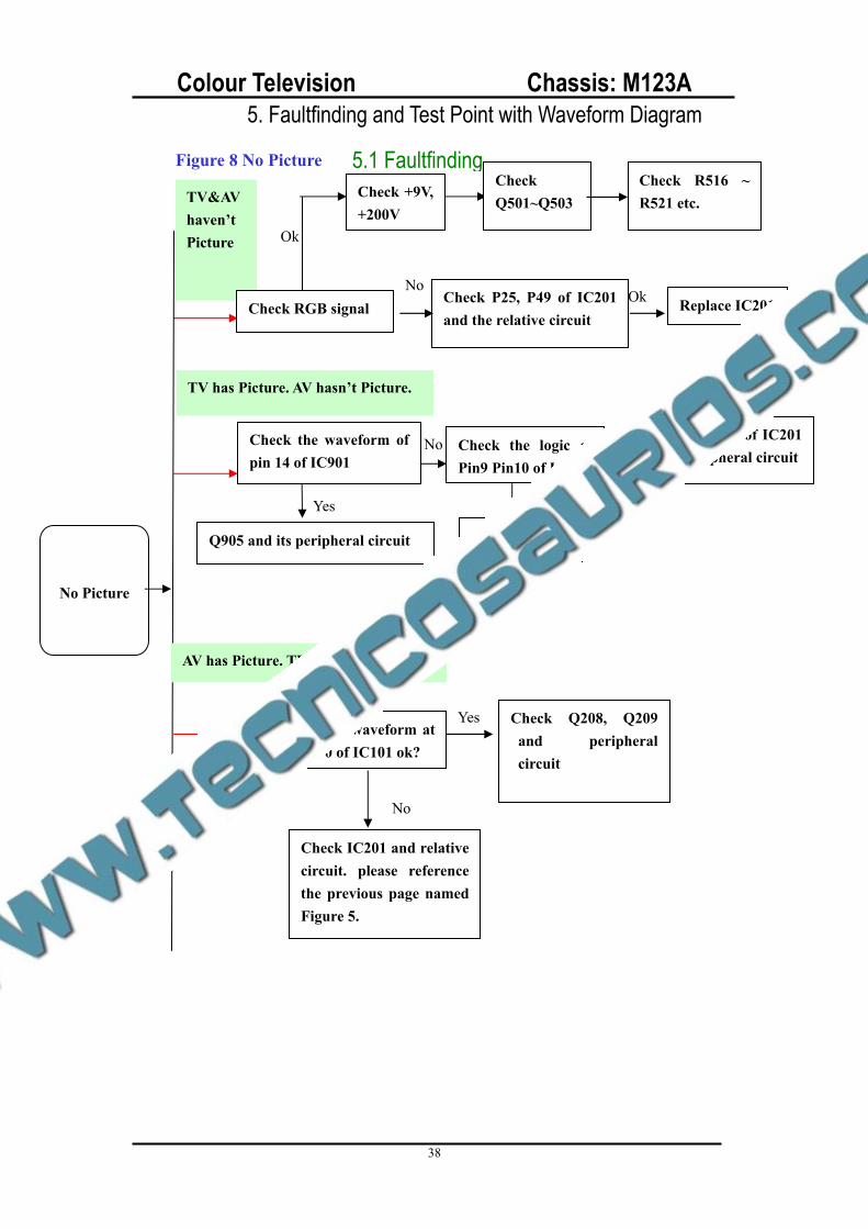
No Picture
TV&AV haven’tPicture
Check RGB signal
Check +9V, +200V
Ok
CheckQ501~Q503
Check R516 ~ R521 etc.
NoOk Replace IC201
TV has Picture. AV hasn’t Picture.
Check the waveform of pin 14 of IC901
No
Q905 and its peripheral circuit
No Check Pin61 of IC201 and peripheral circuit
Check the logic of Pin9 Pin10 of IC901
Yes
Replace IC901
Yes
AV has Picture. TV hasn’t Picture.
Is the waveform at P30 of IC101 ok?
Check Q208, Q209 and peripheral circuit
Yes
Check IC201 and relative circuit. please reference the previous page named Figure 5.
No
Figure 8 No Picture
5. Faultfinding and Test Point with Waveform Diagram
5.1 Faultfinding
Colour Television Chassis: M123A
39
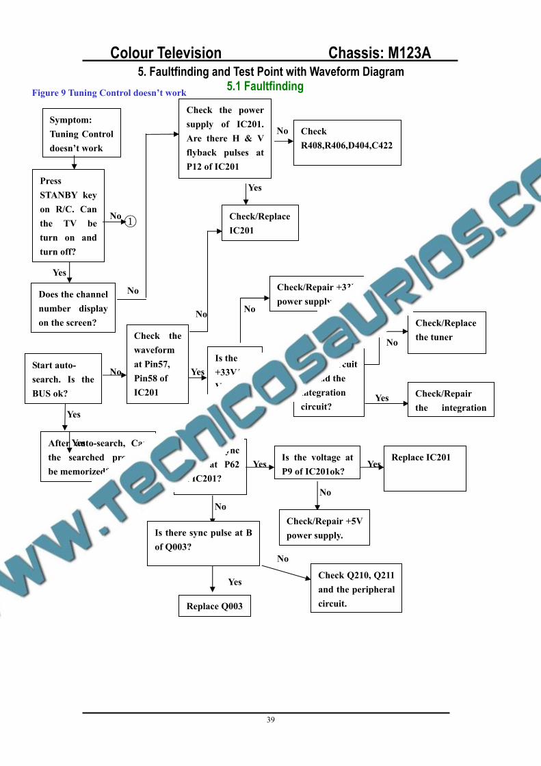
Symptom:Tuning Control doesn’t work
Press STANBY key on R/C. Can the TV be turn on and turn off?
Does the channel number display on the screen?
Yes
No
Start auto- search. Is the BUS ok?
Yes
After auto-search, Can the searched program be memorized?
Is the voltage at P9 of IC201ok?
Replace IC201Yes Yes
Check/Repair +5V power supply.
No
No Is there sync pulse at P62 of IC201?
No
Check the power supply of IC201. Are there H & V flyback pulses at P12 of IC201
No
No CheckR408,R406,D404,C422
Yes
Check/ReplaceIC201
No
Check the waveform at Pin57, Pin58 of IC201
No
Yes Is the +33V/+5VA powersupplyok?
Check/Repair +33V power supply
No
Yes
Is there the short circuit around the integration circuit?
Check/Replacethe tunerNo
Check/Repair the integration
Yes
Figure 9 Tuning Control doesn’t work
Is there sync pulse at B of Q003?
Replace Q003
Yes Check Q210, Q211 and the peripheral circuit.
No
Yes
5. Faultfinding and Test Point with Waveform Diagram 5.1 Faultfinding
Colour Television Chassis: M123A
40
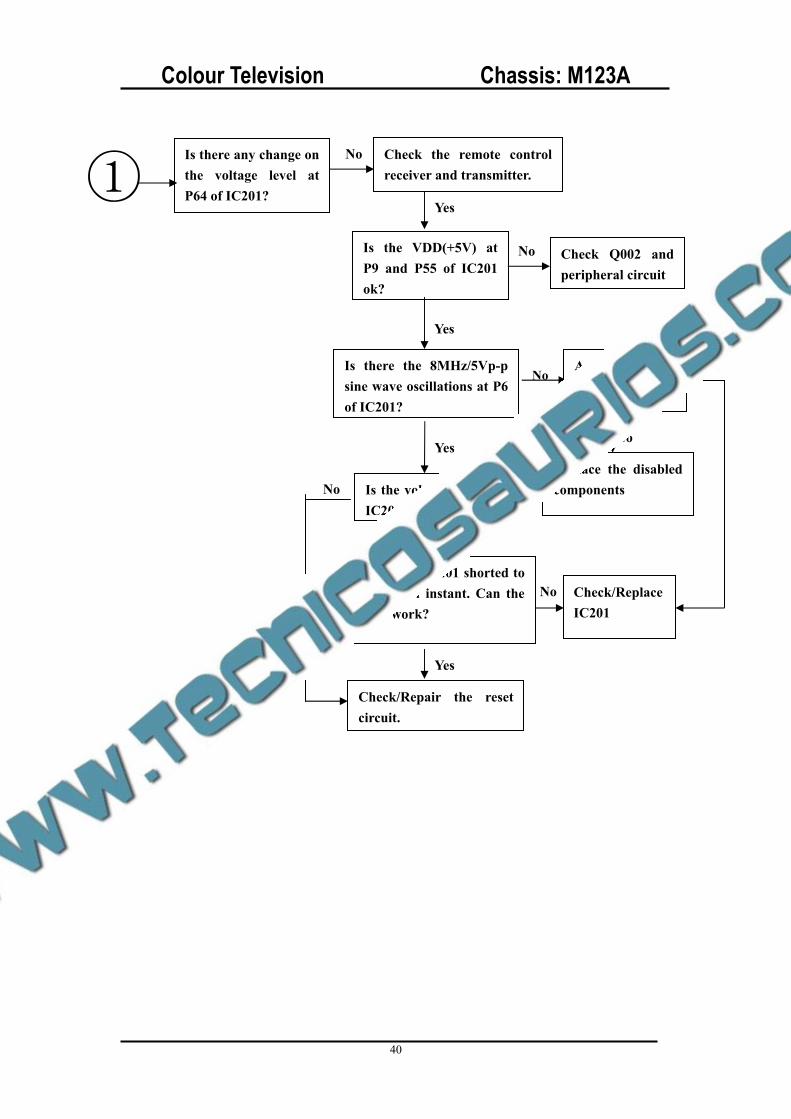
Is there any change on the voltage level at P64 of IC201?
No Check the remote control receiver and transmitter.
Yes
Is the VDD(+5V) at P9 and P55 of IC201 ok?
Is there the 8MHz/5Vp-p sine wave oscillations at P6 of IC201?
Is the voltage at P5 of IC201 ok?
Have P5 of IC201 shorted to GND in an instant. Can the IC201 work?
Check/Repair the reset circuit.
Yes
Yes
Yes
No
Check/ReplaceIC201
No
No
Are C021, C022and X001 ok?
No
Replace the disabled components
YesNo
Check Q002 and peripheral circuit
Yes
Colour Television Chassis: M123A
41
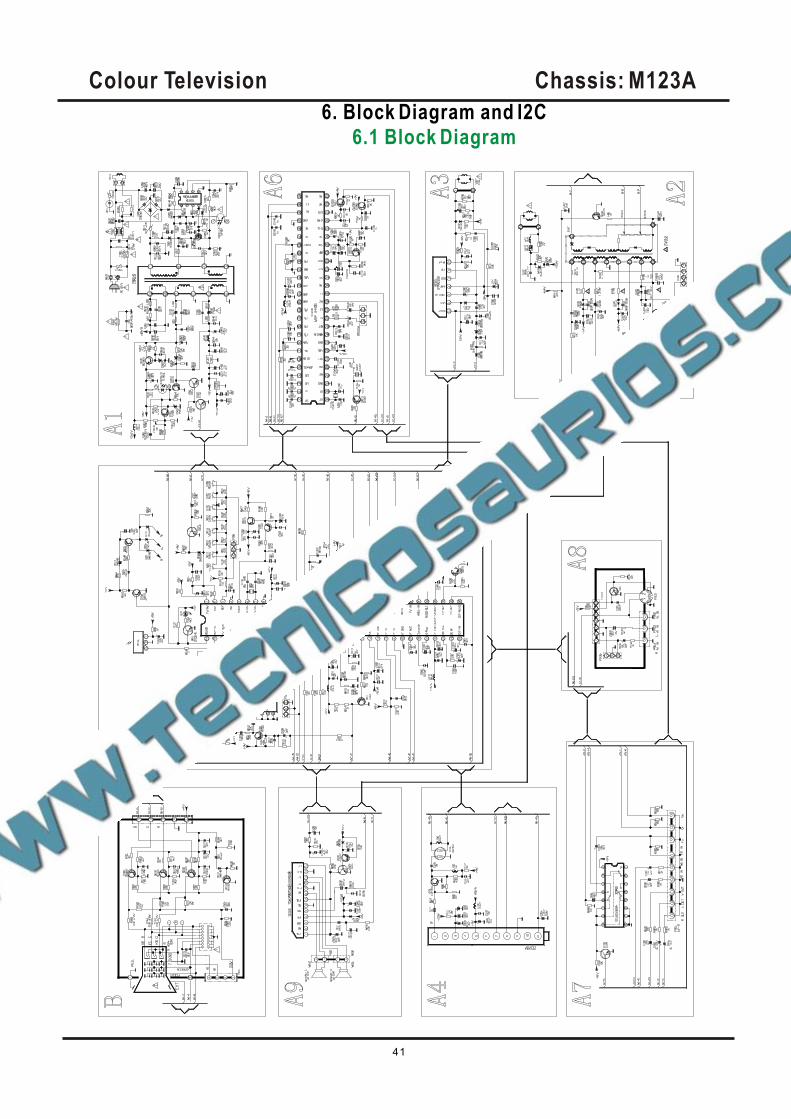
6. Block Diagram and I2C
6.1 Block Diagram
Colour Television Chassis: M123A
42
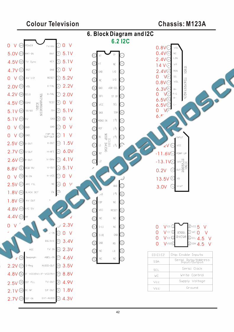
0 V
5.1V
5.1V
0 V
5.2V
2.2V
2.0V
0 V
5.1V
0 V
0 V
1 V
1.5V
6.0V
4.1V
5.1V
0 V
0 V
2.3V
2.6V
2.3V
0 V
2.3V
0 V
3.4V
2.3V
4.6V
3.5V
8.8V
4.9V
1.8V
4.3V2.7V
2.1V
2.5V
4.5V
2.2V
4.8V
4.1V
0 V
0 V
0 V
4.4V
4.8V
1.8V
1.8V
2.5V
0 V
8.8V
2.6V
2.7V
2.5V
0 V
0 V
5.1V
5.1V
4.5V
4.2V
2.0V
0 V
4.7V
4.5V
5.0V
0 V 0.8V
0.4V
2.4V
14 V
2.4V0 V
0.8V
6.3V0 V
6.5V6.5V0 V
6.5V
3.0V
13.2V
-11.6V
-13.1V
0.2V
13.5V
3.0V
0 V0 V
0 V
0 V 4.5 V
4.5 V
5 V
0 V
6. Block Diagram and I2C
6.2 I2C
Colour Television Chassis: M123A
43
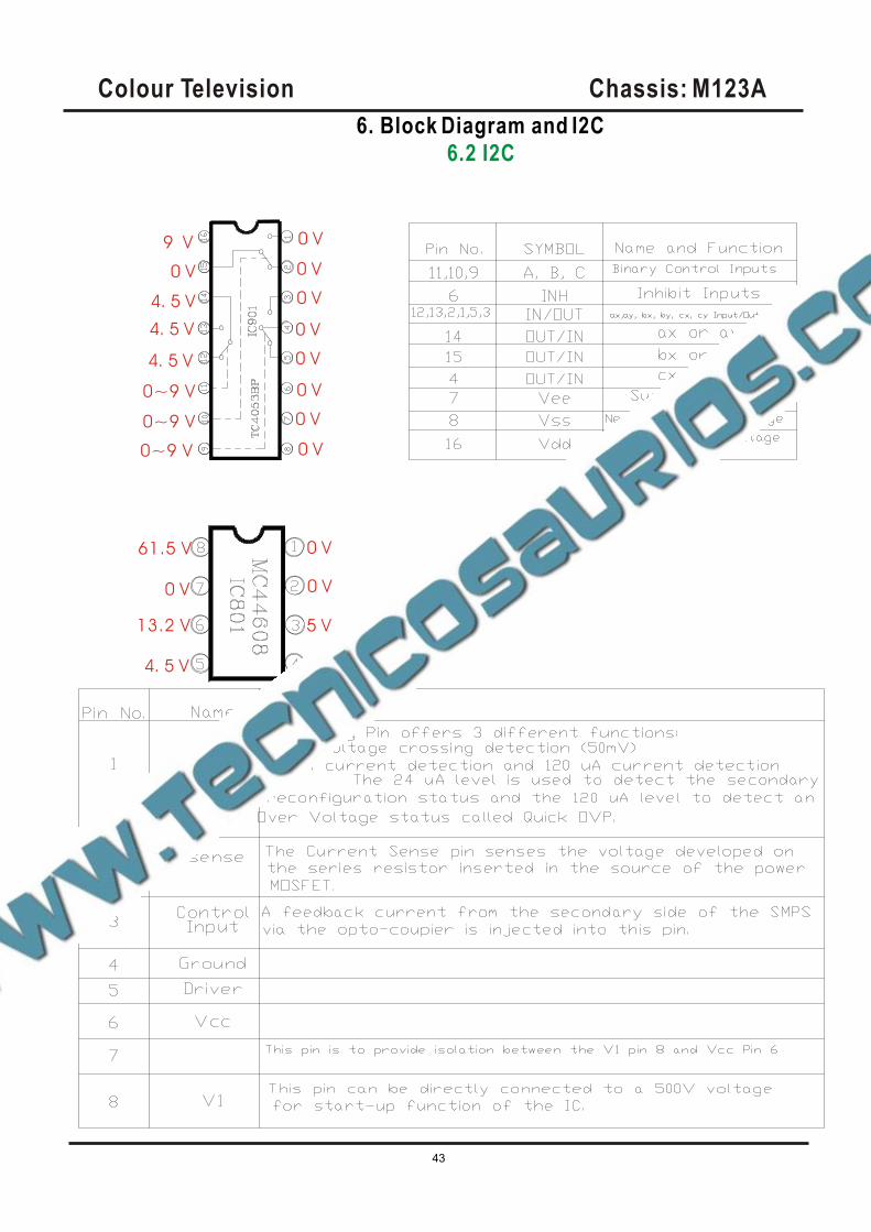
6. Block Diagram and I2C
6.2 I2C
0 V
0 V
61.5 V
0 V
0 V
5 V
4. 5 V
0 V
0 V
0 V
0 V
0 V
0 V
0 V
0 V
0~9 V
0~9 V
0~9 V
13.2 V
4. 5 V
4. 5 V
4. 5 V
0 V
9 V
Colour Television Chassis: M123A
44
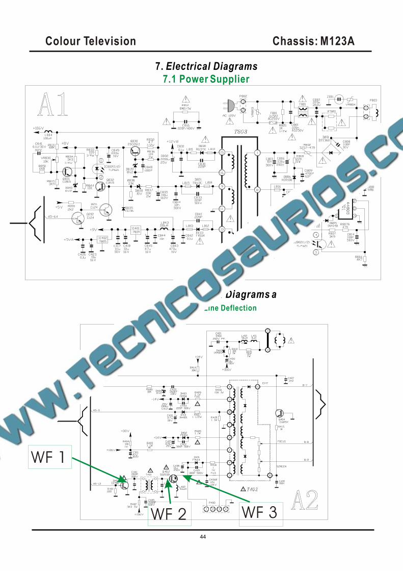
7. Electrical Diagrams
7.1 Power Supplier
7. Electrical Diagrams a
7.2 Line Deflection
WF 1
WF 2 WF 3
Colour Television Chassis: M123A
45
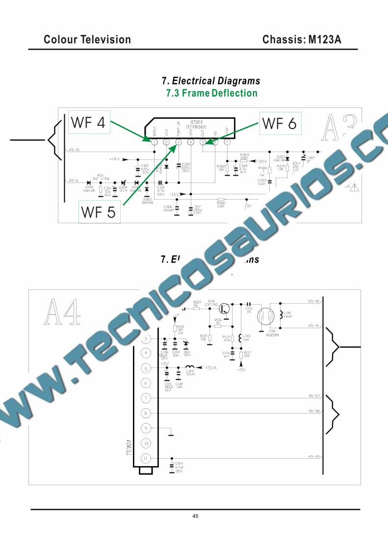
7. Electrical Diagrams
7.3 Frame Deflection
7. Electrical Diagrams
7.4 Tuner IF .
WF 4
WF 5
WF 6
Colour Television Chassis: M123A
46
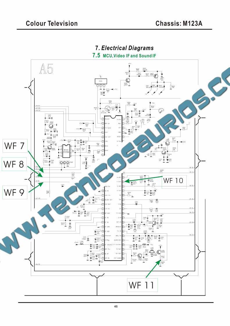
7. Electrical Diagrams
7.5 MCU,Video IF and Sound IF
WF 7
WF 8
WF 9
WF 10
WF 11
Colour Television Chassis: M123A
47
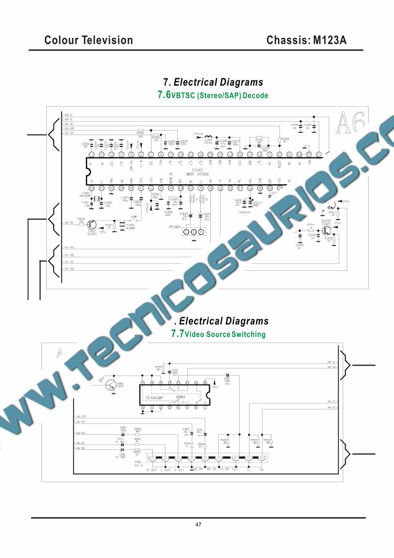
7. Electrical Diagrams
7.6VBTSC (Stereo/SAP) Decode
7. Electrical Diagrams
7.7Video Source Switching
Colour Television Chassis: M123A
48
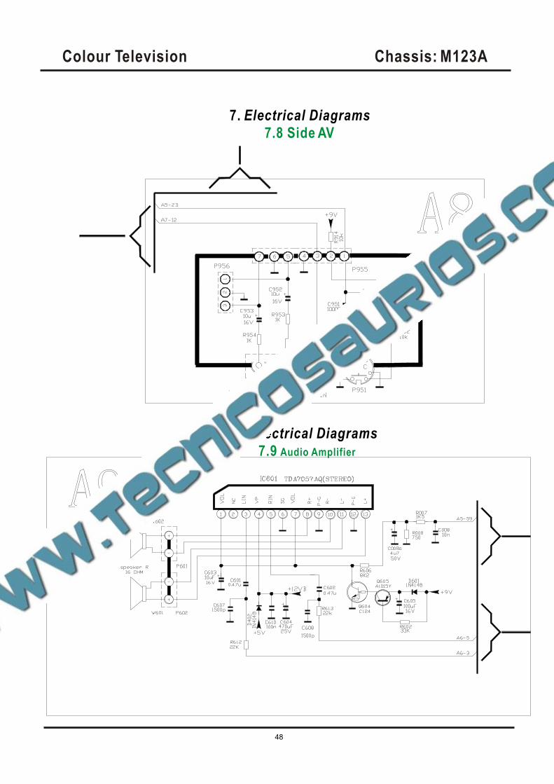
7. Electrical Diagrams
7.8 Side AV
7. Electrical Diagrams
7.9 Audio Amplifier
Colour Television Chassis: M123A
49
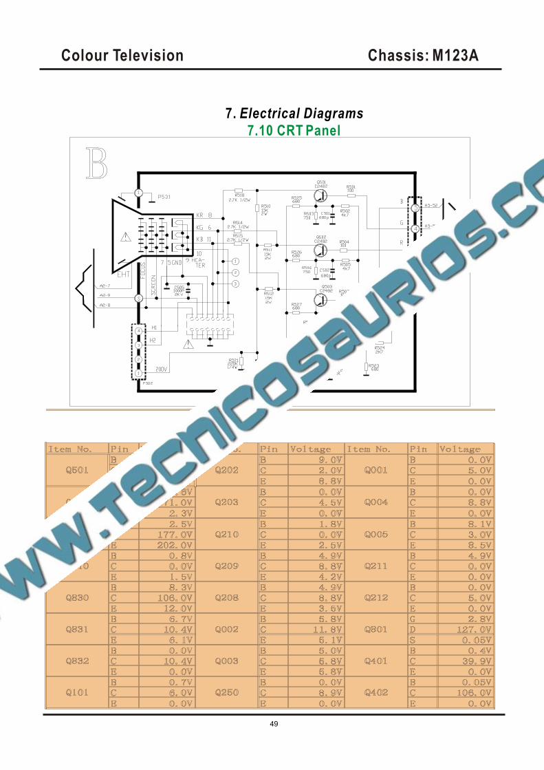
7. Electrical Diagrams
7.10 CRT Panel
Colour Television Chassis: M123A
50
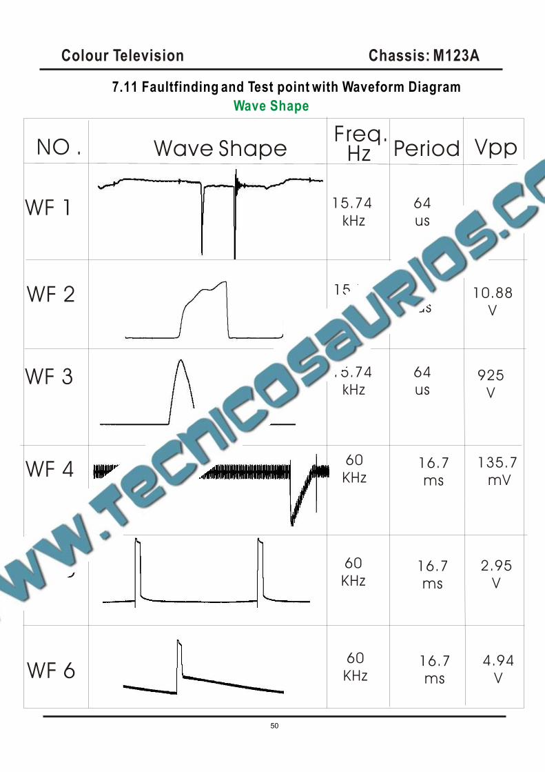
7.11 Faultfinding and Test point with Waveform Diagram
Wave Shape
NO . Wave ShapeFreq.
VppPeriodHz
WF 1 15.74
kHz
64
us2.77
V
WF 3 15.74
kHz
64
us925
V
WF 2 15.74
kHz
64
us10.88
V
WF 4
WF 5
WF 6
60
KHz16.7
ms
135.7
mV
60
KHz16.7
ms
2.95
V
60
KHz16.7
ms
4.94
V
Colour Television Chassis: M123A
51
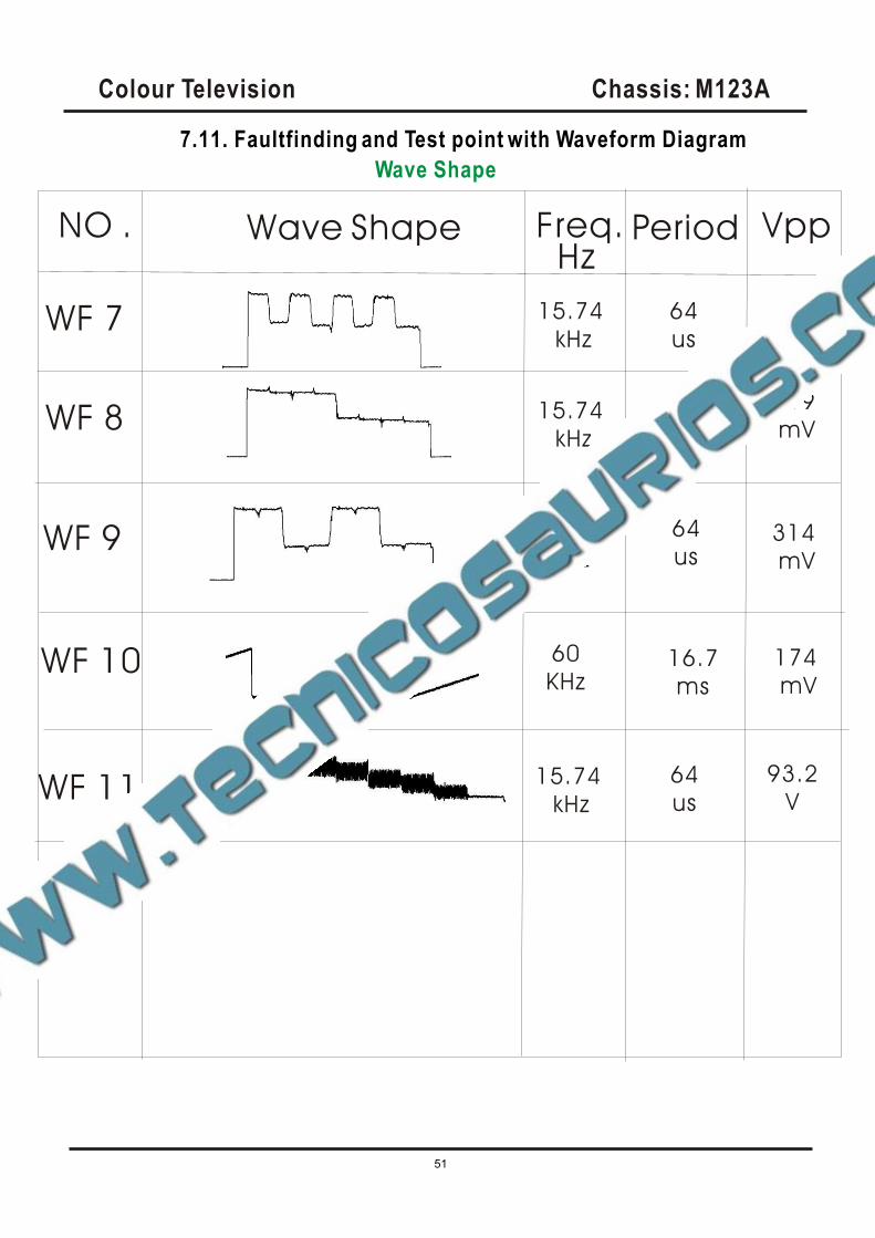
7.11. Faultfinding and Test point with Waveform Diagram
Wave Shape
NO . Wave Shape Freq. VppPeriod
WF 7
Hz
15.74
kHz
64
us345
mV
WF 8 15.74
kHz
WF 9 15.74
kHz
WF 10 60
KHz16.7
ms
15.74
kHz
93.2
V
64
us
64
us
319
mV
314
mV
174
mV
64
usWF 11
Colour Television Chassis: M123A
52
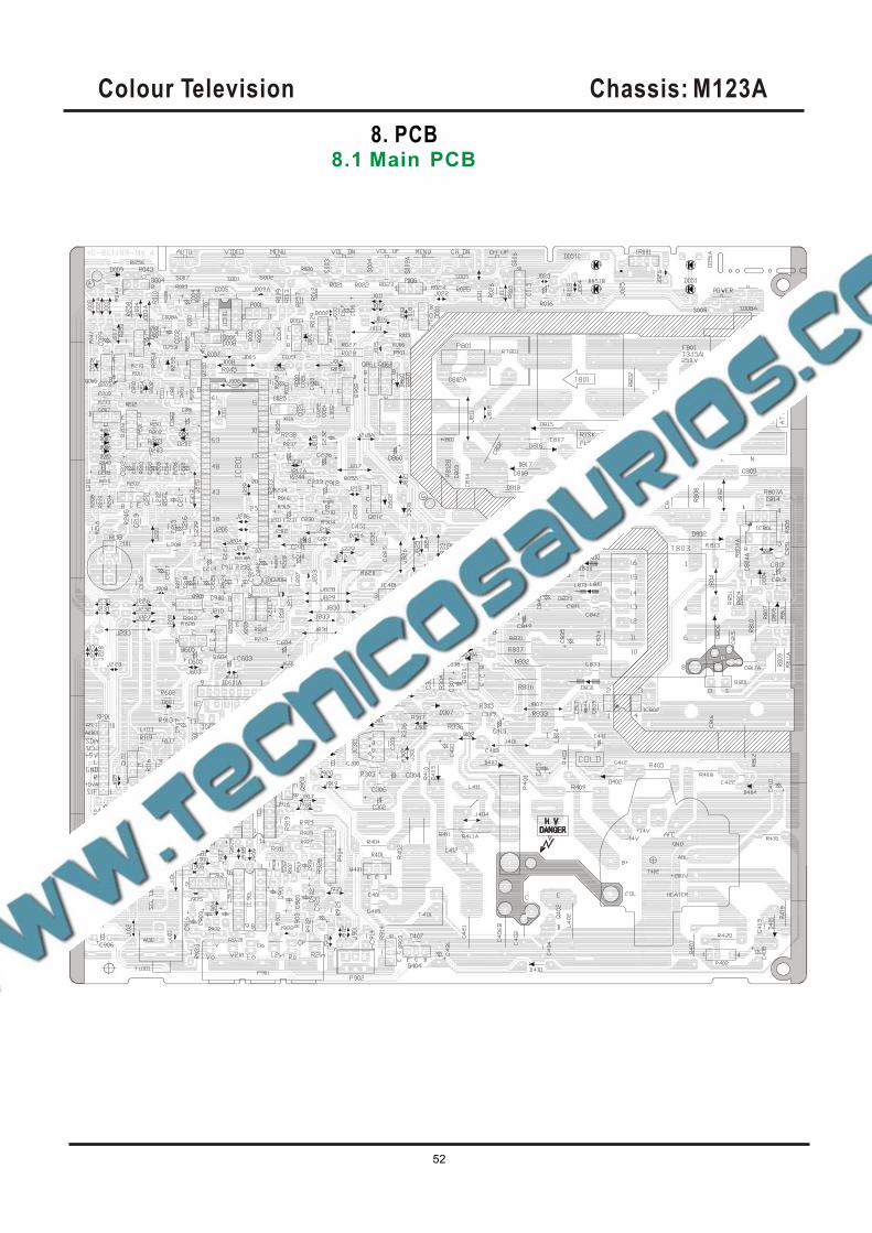
8. PCB8.1 Main PCB
Colour Television Chassis: M123A
53
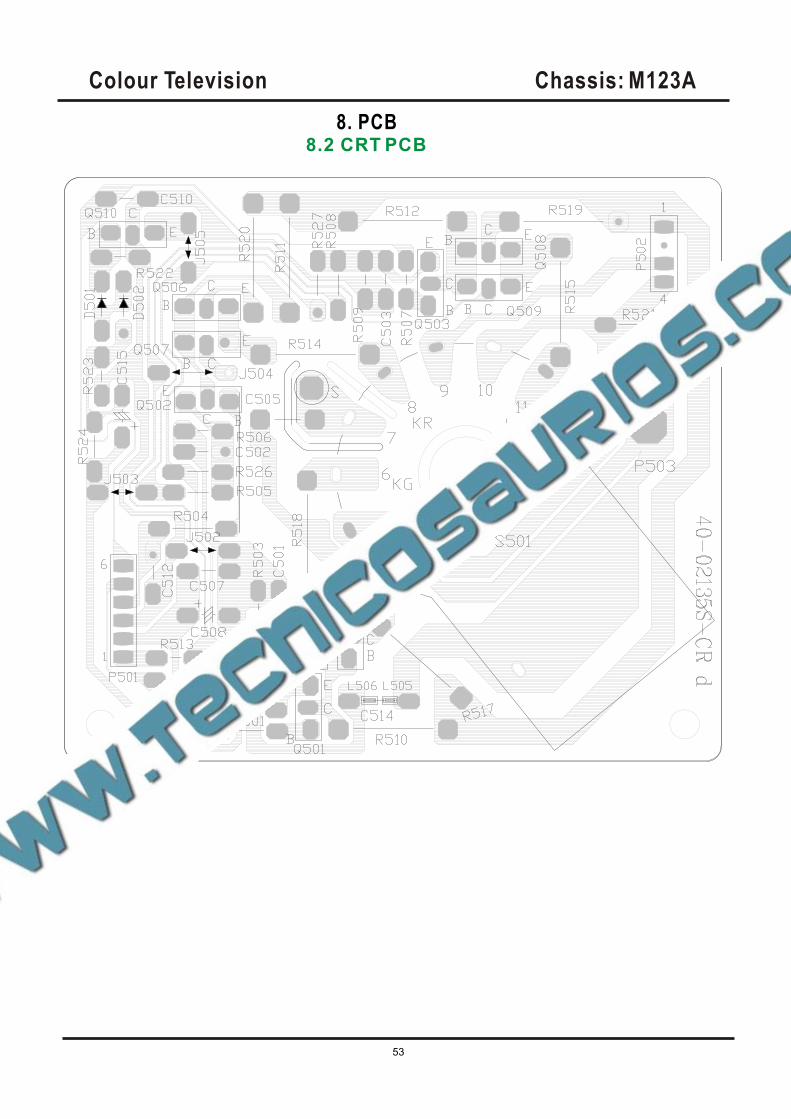
8. PCB8.2 CRT PCB
Colour Television Chassis: M123A
54
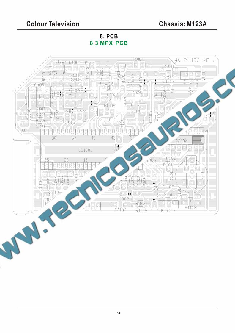
8. PCB8.3 MPX PCB
Colour Television Chassis: M123A
55
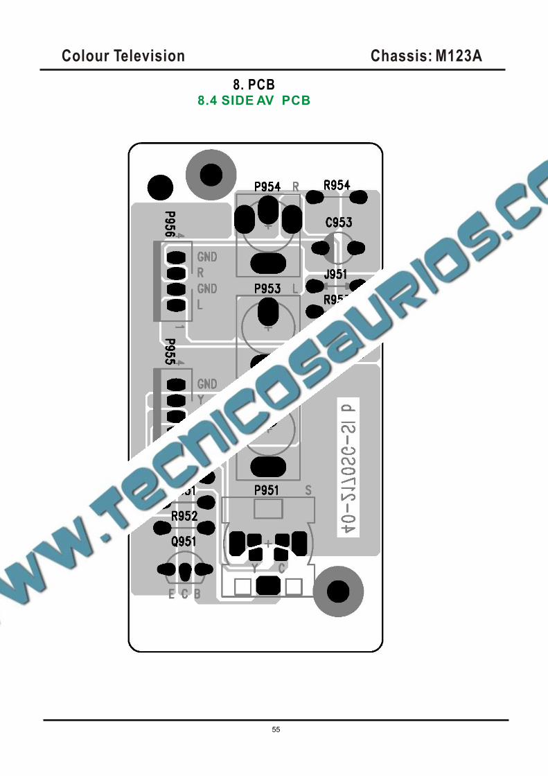
8. PCB8.4 SIDE AV PCB
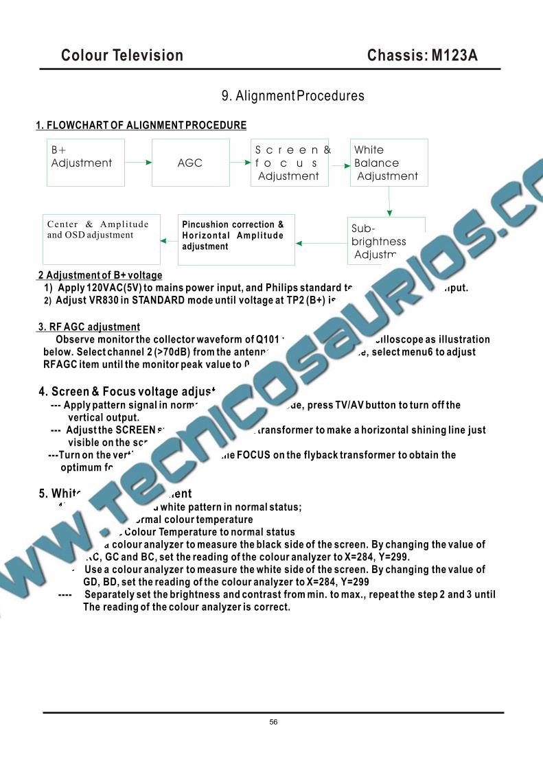
1. FLOWCHART OF ALIGNMENT PROCEDURE
2 Adjustment of B+ voltage1) Apply 120VAC(5V) to mains power input, and Philips standard testing pattern to RF input.2) Adjust VR830 in STANDARD mode until voltage at TP2 (B+) is 106V 0.5V.
3. RF AGC adjustment Observe monitor the collector waveform of Q101 with the probe of Oscilloscope as illustration below. Select channel 2 (>70dB) from the antenna input. Enter D-mode, select menu6 to adjust RFAGC item until the monitor peak value to 0.8V .p-p
4. Screen & Focus voltage adjustment --- Apply pattern signal in normal status, enter D-mode, press TV/AV button to turn off the vertical output. --- Adjust the SCREEN switch on the flyback transformer to make a horizontal shining line just visible on the screen. ---Turn on the vertical output, adjust the FOCUS on the flyback transformer to obtain the optimum focus.
5. White balance adjustment 1)Apply the black and white pattern in normal status; 2)Alignment of normal colour temperature ---- Change Colour Temperature to normal status ---- Use a colour analyzer to measure the black side of the screen. By changing the value of RC, GC and BC, set the reading of the colour analyzer to X=284, Y=299. ---- Use a colour analyzer to measure the white side of the screen. By changing the value of GD, BD, set the reading of the colour analyzer to X=284, Y=299 ---- Separately set the brightness and contrast from min. to max., repeat the step 2 and 3 until The reading of the colour analyzer is correct.
Colour Television Chassis: M123A
56
9. Alignment Procedures
Center & Ampli tudeand OSD adjustment
B+
Adjustment AGC
S c r e e n &
f o c u s
Adjustment
White
Balance
Adjustment
Sub-
brightness
Adjustment
Pincushion correction &Hor izonta l Ampl i tude adjustment
Colour Television Chassis: M123A
57
3)Alignment of warm colour temperature Change Color Temperature to warm status Use a colour analyzer to measure the black side of the screen. By changing the value of RC-W,
GC-W and BC-W, set the reading of the colour analyzer to X=296, Y=294. Use a colour analyzer to measure the white side of the screen. By changing the value of GD-W,
BD-W set the reading of the colour analyzer to X=296, Y=294. Separately set the brightness and contrast from min. to max., repeat the step 2 and 3 until the
reading of the colour analyzer is correct. 4)Alignment of cold colour temperature
Change Color Temperature to cold status Use a colour analyzer to measure the black side of the screen. By changing the value of RC-C,
GC-C BC-C , set the reading of the colour analyzer to X=279, Y=265. Use a colour analyzer to measure the white side of the screen. By changing the value of GD-C,
BD-C, set the reading of the colour analyzer to X=279, Y=265. Separately set the brightness and contrast from min. to max., repeat the step 2 and 3 until the
reading of the colour analyzer is correct Note: Provided the production line is equipped with the self- White balance adjusting equipment, white balance of M123A chassis can be adjusted automatically as following: Press IC BUS button under factory mode, the TV set will adjust automatically.
6. Adjustment of Sub-brightness, Apply the Grey-scale/Color bar (NTSC signal) to the AV input, in normal status.
nd Select BRTC to adjust the sub-brightness, until that the 2 dark bar of 8 level Grey scale just can be seen.
7. PAL picture geometric adjustment menu 3 HPOS6/HPOS5 HZ horizontal center of 60/50 HZ Source
Menu 2 HIGH6/HIGH5(vertical amplitude) VCEN5/VCEN6(position of vertical center) VP60/VP50 vertical position VLIN6/VLIN5 vertical linearity VSC6/VSC5 V-S Correction
8 initialization
press sound-effect under factory mode, the set will initialize, until OK appears on the screen
which means the initialization is finished. After initialization, the set will quit factory mode
Automatically.
9. Alignment Procedures
Colour Television Chassis: M123A
58
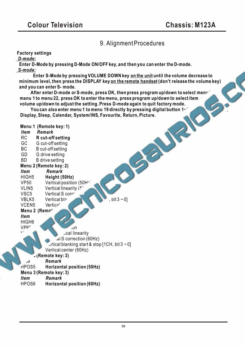
Factory settings D-mode: Enter D-Mode by pressing D-Mode ON/OFF key, and then you can enter the D-mode. S-mode:
Enter S-Mode by pressing VOLUME DOWN key on the unit until the volume decrease to minimum level, then press the DISPLAY key on the remote handset (don't release the volume key) and you can enter S- mode.
After enter D-mode or S-mode, press OK, then press program up/down to select menu frommenu 1 to menu 22, press OK to enter the menu, press program up/down to select item, pressvolume up/down to adjust the setting. Press D-mode again to quit factory mode.
You can also enter menu 1 to menu 19 directly by pressing digital button 1~9, 0, notebook, CAP,Display, Sleep, Calendar, System/INS, Favourite, Return, Picture.
Menu 1 (Remote key: 1)Item RemarkRC R cut-off settingGC G cut-off settingBC B cut-off settingGD G drive settingBD B drive setting
Menu 2 (Remote key: 2)Item RemarkHIGH5 Height (50Hz)VP50 Vertical position (50Hz)VLIN5 Vertical linearity (50Hz)VSC5 Vertical S correction (50Hz)VBLK5 Vertical blanking start & stop [1C, bit 3 ~ 0]VCEN5 Vertical center (50Hz)Menu 2 (Remote key: 2)Item RemarkHIGH6 60Hz heightVP60 Vertical positionVLIN6 60Hz Vertical linearityVSC6 Vertical S correction (60Hz)VBLK6 Vertical blanking start & stop [1CH, bit 3 ~ 0]VCEN6 Vertical center (60Hz)Menu 3 (Remote key: 3)Item RemarkHPOS5 Horizontal position (50Hz)Menu 3 (Remote key: 3)Item RemarkHPOS6 Horizontal position (60Hz)
9. Alignment Procedures
Colour Television Chassis: M123A
59
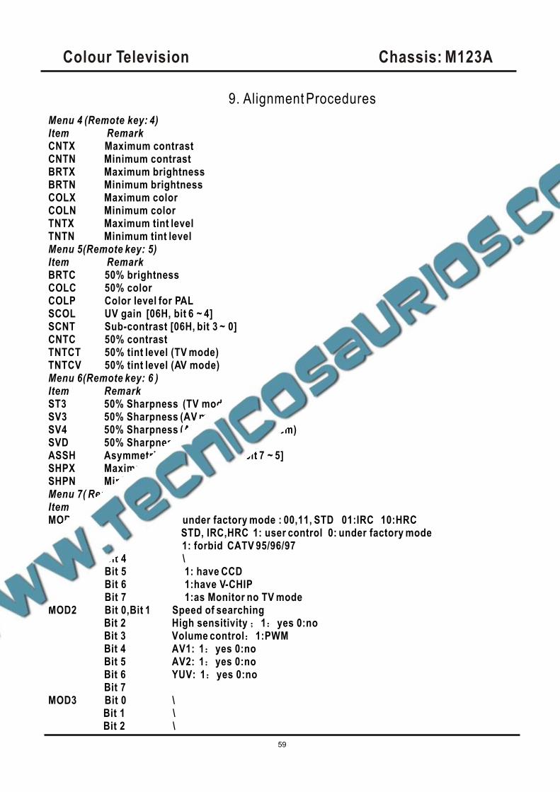
Menu 4 (Remote key: 4)Item RemarkCNTX Maximum contrastCNTN Minimum contrastBRTX Maximum brightnessBRTN Minimum brightnessCOLX Maximum colorCOLN Minimum colorTNTX Maximum tint levelTNTN Minimum tint levelMenu 5(Remote key: 5)Item RemarkBRTC 50% brightnessCOLC 50% colorCOLP Color level for PALSCOL UV gain [06H, bit 6 ~ 4]SCNT Sub-contrast [06H, bit 3 ~ 0]CNTC 50% contrastTNTCT 50% tint level (TV mode)TNTCV 50% tint level (AV mode)Menu 6(Remote key: 6 )Item RemarkST3 50% Sharpness (TV mode, 3.58 system)SV3 50% Sharpness (AV mode, 3.58 system)SV4 50% Sharpness (AV mode, other system)SVD 50% Sharpness (DVD mode)ASSH Asymmetric sharpness [04H, bit 7 ~ 5]SHPX Maximum sharpnessSHPN Minimum sharpnessMenu 7( Remote key: 7)Item RemarkMOD1 Bit 0,Bit 1 under factory mode : 00,11, STD 01:IRC 10:HRC
Bit 2 STD, IRC,HRC 1: user control 0: under factory mode Bit 3 1: forbid CATV 95/96/97Bit 4 \Bit 5 1: have CCDBit 6 1:have V-CHIPBit 7 1:as Monitor no TV mode
MOD2 Bit 0,Bit 1 Speed of searchingBit 2 High sensitivity 1 yes 0:noBit 3 Volume control 1:PWMBit 4 AV1: 1 yes 0:noBit 5 AV2: 1 yes 0:noBit 6 YUV: 1 yes 0:noBit 7
MOD3 Bit 0 \Bit 1 \Bit 2 \
9. Alignment Procedures
Colour Television Chassis: M123A
60
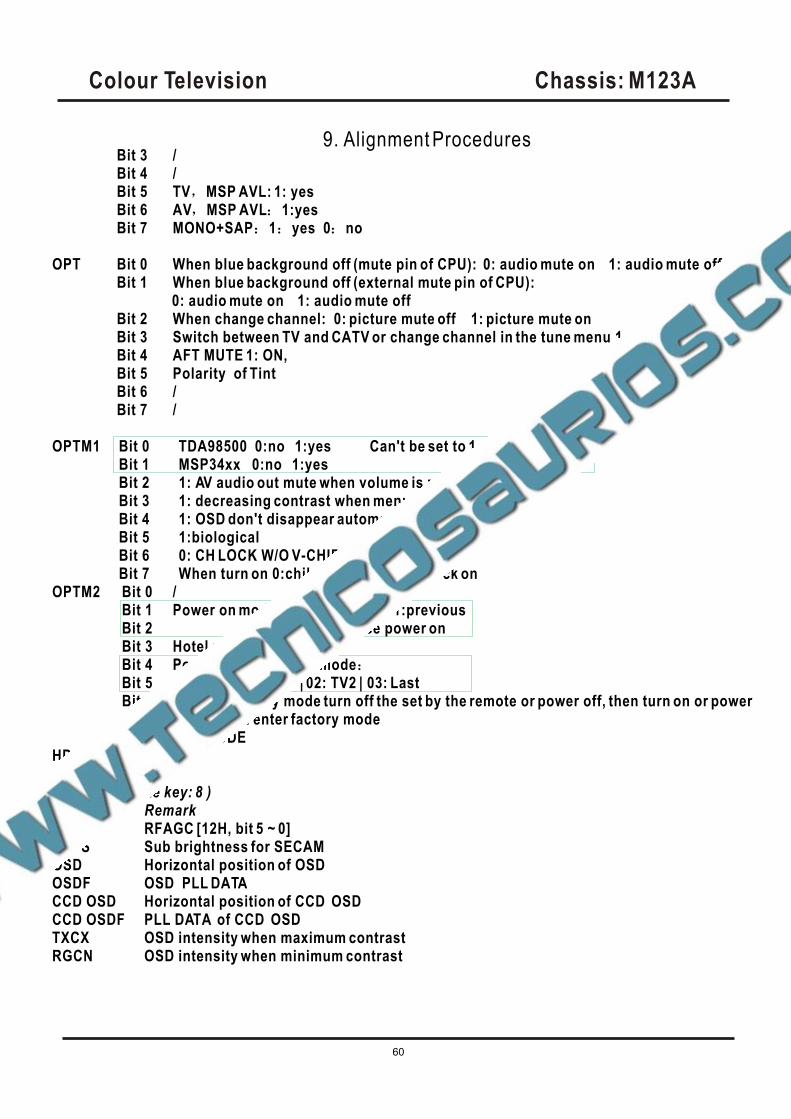
Bit 3 /Bit 4 /Bit 5 TV MSP AVL: 1: yesBit 6 AV MSP AVL 1:yesBit 7 MONO+SAP 1 yes 0 no
OPT Bit 0 When blue background off (mute pin of CPU): 0: audio mute on 1: audio mute offBit 1 When blue background off (external mute pin of CPU):
0: audio mute on 1: audio mute offBit 2 When change channel: 0: picture mute off 1: picture mute on Bit 3 Switch between TV and CATV or change channel in the tune menu 1: picture mute onBit 4 AFT MUTE 1: ON,Bit 5 Polarity of TintBit 6 /Bit 7 /
OPTM1 Bit 0 TDA98500 0:no 1:yes Can't be set to 1 at the same timeBit 1 MSP34xx 0:no 1:yesBit 2 1: AV audio out mute when volume is zero or muteBit 3 1: decreasing contrast when menu onBit 4 1: OSD don't disappear automaticallyBit 5 1:biologicalBit 6 0: CH LOCK W/O V-CHIPBit 7 When turn on 0:child lock off 1:child lock on
OPTM2 Bit 0 /Bit 1 Power on mode: 00: standby 01:previousBit 2 10&11: force power onBit 3 Hotel mode 1:on 0: off Bit 4 Power on under hotel modeBit 5 00: TV | 01: Video1 | 02: TV2 | 03: LastBit 6 1: under factory mode turn off the set by the remote or power off, then turn on or power
on, the set enter factory modeBit 7 1: D-MODE
HDCNTHSTOPMenu 8 (Remote key: 8 )Item RemarkRFAGC RFAGC [12H, bit 5 ~ 0]BRTS Sub brightness for SECAMOSD Horizontal position of OSDOSDF OSD PLL DATACCD OSD Horizontal position of CCD OSD CCD OSDF PLL DATA of CCD OSD TXCX OSD intensity when maximum contrastRGCN OSD intensity when minimum contrast
9. Alignment Procedures
Colour Television Chassis: M123A
61
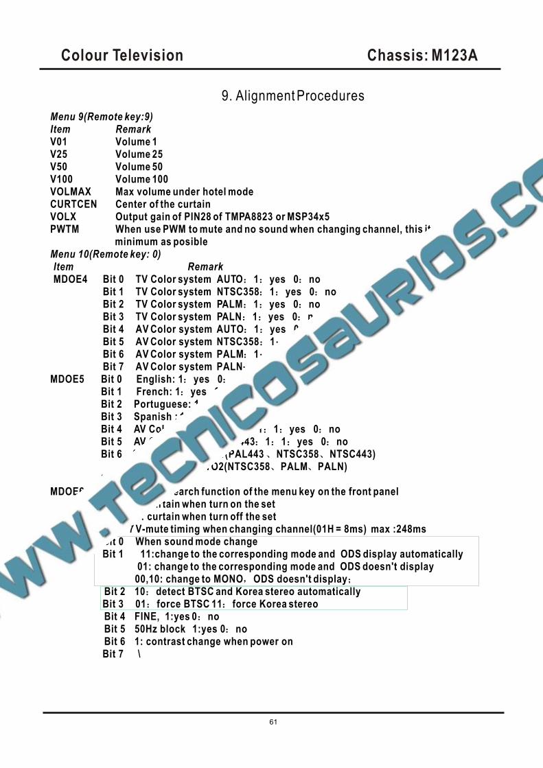
Menu 9(Remote key:9)Item RemarkV01 Volume 1V25 Volume 25V50 Volume 50 V100 Volume 100VOLMAX Max volume under hotel modeCURTCEN Center of the curtainVOLX Output gain of PIN28 of TMPA8823 or MSP34x5PWTM When use PWM to mute and no sound when changing channel, this item should be minimum as posibleMenu 10(Remote key: 0)Item RemarkMDOE4 Bit 0 TV Color system AUTO 1 yes 0 no
Bit 1 TV Color system NTSC358 1 yes 0 noBit 2 TV Color system PALM 1 yes 0 noBit 3 TV Color system PALN 1 yes 0 noBit 4 AV Color system AUTO 1 yes 0 noBit 5 AV Color system NTSC358 1 yes 0 noBit 6 AV Color system PALM 1 yes 0 noBit 7 AV Color system PALN 1 1 yes 0 no
MDOE5 Bit 0 English: 1 yes 0 noBit 1 French: 1 yes 0 noBit 2 Portuguese: 1 yes 0 noBit 3 Spanish : 1 yes 0 noBit 4 AV Color system PAL443 1 1 yes 0 noBit 5 AV Color system NTSC443 1 1 yes 0 noBit 6 AV AUTO 1:AUTO1(PAL443 NTSC358 NTSC443)
0:AUTO2(NTSC358 PALM PALN)Bit 7 \
MDOE6 Bit 0 1:auto search function of the menu key on the front panelBit 1 1: curtain when turn on the set Bit 2 1: curtain when turn off the setBit3~ 7 V-mute timing when changing channel(01H = 8ms) max :248ms
MDOE7 Bit 0 When sound mode change Bit 1 11:change to the corresponding mode and ODS display automatically 01: change to the corresponding mode and ODS doesn't display 00,10: change to MONO ODS doesn't display
Bit 2 10 detect BTSC and Korea stereo automatically Bit 3 01 force BTSC 11 force Korea stereo
Bit 4 FINE, 1:yes 0 noBit 5 50Hz block 1:yes 0 noBit 6 1: contrast change when power on
Bit 7 \
9. Alignment Procedures

Colour Television Chassis: M123A
62
MDOE8 Bit 0 America V-CHIP standard 1 yes 0 noBit 1 Canadian V-CHIP 1 yes 0 noBit 2 UNRATED 1 yes 0 noBit 3 NO RATING 1 yes 0 noBit 4 ~Bit 7 Time setting for curtain when turn on the set
MDOE9 Bit 0 ~Bit 2 N/ABit 3 S-VIDEO ,0:parallel to AV1 1: parallel to AV2Bit 4 1:sound effect w/o mpx (MSP3465) Bit 5 ~Bit 7 N/A
Menu 12(Remote key: CAP)Item RemarkOSD2 OSD Horizontal PositionOSDF2 OSD PLL DATA except PYNX Normal H.SYNC maxPYNN Normal H.SYNC minPYXS Search H.SYNC maxPYNS Search H.SYNC minMenu 13 (Remote key: Display )Item RemarkCLTM TV modeCLVO Video modeCLVS S-video mode
Bit 2 ~ 0 YDL [15H, bit 2 ~ 0] (-40ns~240ns)Bit 4 ~ 3 NTSC matrix [03H, bit 7 ~ 6] (N1,N2,DVD)Bit 5C gamma [02H, bit 7] (color gamma on/off)Bit 6 P/N ID [17H, bit 4] (PAL/NTSC killer sensit.)Bit 7 FID [17H, bit 3] (Killer off)
ABL Bit 1 ~ 0 ABL gain [16H, bit 5 ~ 4] Bit 3 ~ 2 ABL start point [16H, bit 7 ~ 6] Bit 4 WPS [00H, bit 7] Bit 5 OSD ABCL [16H, bit 3]
DCBS Bit 1 ~ 0 Black stretch [15H, bit 4 ~ 3]Bit 3 ~ 2 Y gamma [15H, bit 6 ~ 5]
Bit 5 ~ 4 OSD level [16H, bit 1 ~ 0]Bit 7 Blank switch [0CH, bit 7]
FLG0 Bit 0 Over modulation [13H, bit 5]Bit 1 Aft window size [13H, bit 6]Bit 2 Buzz reducer [13H, bit 7]Bit 3 Audio gain switch [14H, bit 7]Bit 4Bit 5Bit 6Bit 7 1: VCO adjust automatically when changing channel
FLG1 Bit 0 CW SW [06H, bit 7], control PIN26,Bit 1 Slice level [1EH, bit 6]Bit 2 Mix gain [15H, bit 7]Bit 3 V ramp bias [1DH, bit 4]
Bit 4Bit 5Bit 6Bit 7 SLO f0 shift(test only)
9. Alignment Procedures
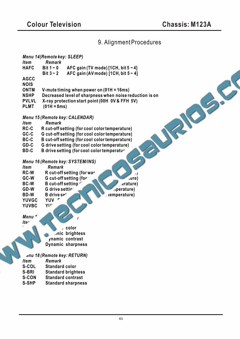
Colour Television Chassis: M123A
63
Menu 14(Remote key: SLEEP)Item RemarkHAFC Bit 1 ~ 0 AFC gain (TV mode) [1CH, bit 5 ~ 4]
Bit 3 ~ 2 AFC gain (AV mode) [1CH, bit 5 ~ 4]AGCCNOISONTM V-mute timing when power on (01H = 16ms)NSHP Decreased level of sharpness when noise reduction is on PVLVL X-ray protection start point (00H 0V & FFH 5V)PLMT (01H = 8ms)
Menu 15 (Remote key: CALENDAR)Item RemarkRC-C R cut-off setting (for cool color temperature)GC-C G cut-off setting (for cool color temperature)BC-C B cut-off setting (for cool color temperature)GD-C G drive setting (for cool color temperature)BD-C B drive setting (for cool color temperature)
Menu 16 (Remote key: SYSTEM/INS)Item RemarkRC-W R cut-off setting (for warm color temperature)GC-W G cut-off setting (for warm color temperature)BC-W B cut-off setting (for warm color temperature)GD-W G drive setting (for warm color temperature)BD-W B drive setting (for warm color temperature)YUVGC YUV R cut-offYUVBC YUV B cut-off
Menu 17 (Remote key: FAV )Item RemarkD-COL Dynamic colorD-BRI Dynamic brightessD-CON Dynamic contrastD-SHP Dynamic sharpness
Menu 18 (Remote key: RETURN)Item RemarkS-COL Standard colorS-BRI Standard brightessS-CON Standard contrastS-SHP Standard sharpness
9. Alignment Procedures
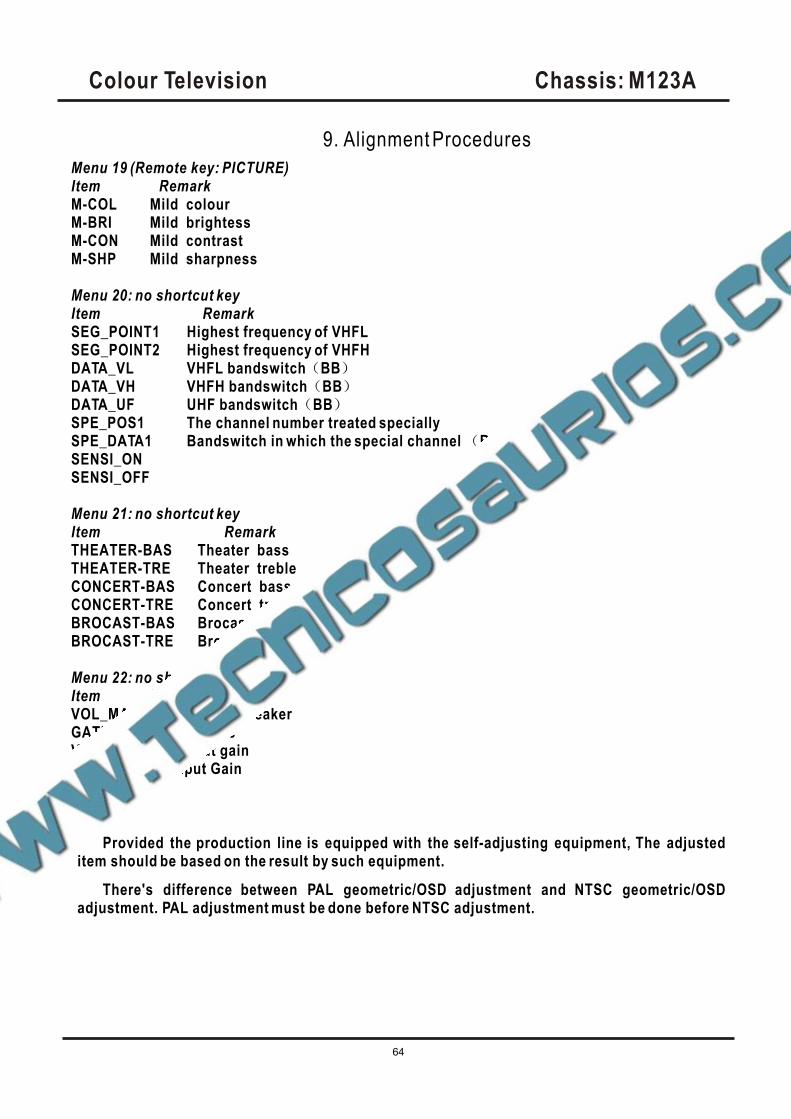
Colour Television Chassis: M123A
64
Menu 19 (Remote key: PICTURE)Item RemarkM-COL Mild colourM-BRI Mild brightessM-CON Mild contrastM-SHP Mild sharpness
Menu 20: no shortcut key Item RemarkSEG_POINT1 Highest frequency of VHFLSEG_POINT2 Highest frequency of VHFHDATA_VL VHFL bandswitch BBDATA_VH VHFH bandswitch BBDATA_UF UHF bandswitch BBSPE_POS1 The channel number treated speciallySPE_DATA1 Bandswitch in which the special channel BBSENSI_ONSENSI_OFF
Menu 21: no shortcut key Item RemarkTHEATER-BAS Theater bassTHEATER-TRE Theater trebleCONCERT-BAS Concert bassCONCERT-TRE Concert trebleBROCAST-BAS Brocast bassBROCAST-TRE Brocast treble
Menu 22: no shortcut key Item RemarkVOL_MAI Volume LoudspeakerGATE Carrier-MuteVOL-OUT AV output gainAV GAIN AV input Gain
Note:
Provided the production line is equipped with the self-adjusting equipment, The adjusteditem should be based on the result by such equipment.
There's difference between PAL geometric/OSD adjustment and NTSC geometric/OSDadjustment. PAL adjustment must be done before NTSC adjustment.
9. Alignment Procedures
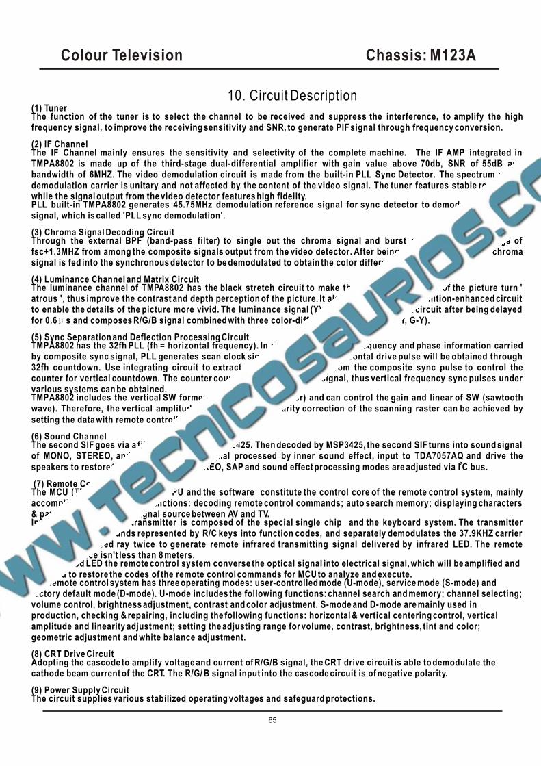
Colour Television Chassis: M123A
65
10. Circuit Description(1) TunerThe function of the tuner is to select the channel to be received and suppress the interference, to amplify the highfrequency signal, to improve the receiving sensitivity and SNR, to generate PIF signal through frequency conversion.
(2) IF ChannelThe IF Channel mainly ensures the sensitivity and selectivity of the complete machine. The IF AMP integrated in TMPA8802 is made up of the third-stage dual-differential amplifier with gain value above 70db, SNR of 55dB and bandwidth of 6MHZ. The video demodulation circuit is made from the built-in PLL Sync Detector. The spectrum of thedemodulation carrier is unitary and not affected by the content of the video signal. The tuner features stable receptivity while the signal output from the video detector features high fidelity.PLL built-in TMPA8802 generates 45.75MHz demodulation reference signal for sync detector to demodulate the videosignal, which is called 'PLL sync demodulation'.
(3) Chroma Signal Decoding Circuit Through the external BPF (band-pass filter) to single out the chroma signal and burst signal within the range of fsc+1.3MHZ from among the composite signals output from the video detector. After being amplified by ACC, the chromasignal is fed into the synchronous detector to be demodulated to obtain the color difference signal.
(4) Luminance Channel and Matrix CircuitThe luminance channel of TMPA8802 has the black stretch circuit to make the 'darkish' ingredient of the picture turn ' atrous ', thus improve the contrast and depth perception of the picture. It also has the delayed definition-enhanced circuit to enable the details of the picture more vivid. The luminance signal (Y) is sent into the matrix circuit after being delayed for 0.6 s and composes R/G/B signal combined with three color-difference signals (B-Y, R-Y, G-Y).
(5) Sync Separation and Deflection Processing CircuitTMPA8802 has the 32fh PLL (fh = horizontal frequency). In accordance with the frequency and phase information carriedby composite sync signal, PLL generates scan clock signal with 32fh and horizontal drive pulse will be obtained through 32fh countdown. Use integrating circuit to extract vertical sync signal from the composite sync pulse to control thecounter for vertical countdown. The counter countdown the 32fh clock signal, thus vertical frequency sync pulses under various systems can be obtained.TMPA8802 includes the vertical SW former (sawtooth wave former) and can control the gain and linear of SW (sawtoothwave). Therefore, the vertical amplitude control and the linearity correction of the scanning raster can be achieved by
2setting the data with remote controller via I C bus input.
(6) Sound ChannelThe second SIF goes via a filter of 4.5MHz, to MSP3425. Then decoded by MSP3425, the second SIF turns into sound signal of MONO, STEREO, and SAP. The sound signal processed by inner sound effect, input to TDA7057AQ and drive the
2speakers to restore the sound. MONO, STEREO, SAP and sound effect processing modes are adjusted via I C bus.
(7) Remote Control SystemThe MCU (TMPA8802) of an 8-bit CPU and the software constitute the control core of the remote control system, mainlyaccomplishing the following functions: decoding remote control commands; auto search memory; displaying characters & patterns; switching the signal source between AV and TV.Infrared remote control transmitter is composed of the special single chip and the keyboard system. The transmitter translates the commands represented by R/C keys into function codes, and separately demodulates the 37.9KHZ carrier and 940nm infrared ray twice to generate remote infrared transmitting signal delivered by infrared LED. The remote control distance isn't less than 8 meters.With infrared LED the remote control system converse the optical signal into electrical signal, which will be amplified and decoded to restore the codes of the remote control commands for MCU to analyze and execute.The remote control system has three operating modes: user-controlled mode (U-mode), service mode (S-mode) andfactory default mode (D-mode). U-mode includes the following functions: channel search and memory; channel selecting;volume control, brightness adjustment, contrast and color adjustment. S-mode and D-mode are mainly used inproduction, checking & repairing, including the following functions: horizontal & vertical centering control, vertical amplitude and linearity adjustment; setting the adjusting range for volume, contrast, brightness, tint and color;geometric adjustment and white balance adjustment.
(8) CRT Drive CircuitAdopting the cascode to amplify voltage and current of R/G/B signal, the CRT drive circuit is able to demodulate the cathode beam current of the CRT. The R/G/ B signal input into the cascode circuit is of negative polarity.
(9) Power Supply CircuitThe circuit supplies various stabilized operating voltages and safeguard protections.
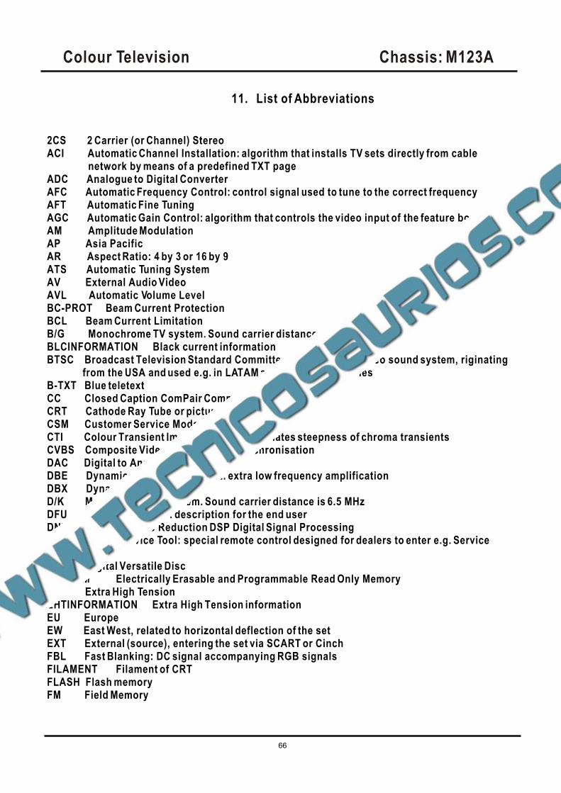
Colour Television Chassis: M123A
66
11. List of Abbreviations
2CS 2 Carrier (or Channel) StereoACI Automatic Channel Installation: algorithm that installs TV sets directly from cable network by means of a predefined TXT pageADC Analogue to Digital ConverterAFC Automatic Frequency Control: control signal used to tune to the correct frequency AFT Automatic Fine TuningAGC Automatic Gain Control: algorithm that controls the video input of the feature boxAM Amplitude ModulationAP Asia PacificAR Aspect Ratio: 4 by 3 or 16 by 9ATS Automatic Tuning SystemAV External Audio VideoAVL Automatic Volume LevelBC-PROT Beam Current ProtectionBCL Beam Current LimitationB/G Monochrome TV system. Sound carrier distance is 5.5 MHzBLCINFORMATION Black current informationBTSC Broadcast Television Standard Committee. Multiplex FM stereo sound system, riginating
from the USA and used e.g. in LATAM and AP-NTSC countriesB-TXT Blue teletextCC Closed Caption ComPair Computer aided rePairCRT Cathode Ray Tube or picture tubeCSM Customer Service ModeCTI Colour Transient Improvement: manipulates steepness of chroma transientsCVBS Composite Video Blanking and SynchronisationDAC Digital to Analogue ConverterDBE Dynamic Bass Enhancement: extra low frequency amplificationDBX Dynamic Bass ExpanderD/K Monochrome TV system. Sound carrier distance is 6.5 MHzDFU Direction For Use: description for the end userDNR Dynamic Noise Reduction DSP Digital Signal ProcessingDST Dealer Service Tool: special remote control designed for dealers to enter e.g. Service modeDVD Digital Versatile DiscEEPROM Electrically Erasable and Programmable Read Only MemoryEHT Extra High TensionEHTINFORMATION Extra High Tension informationEU EuropeEW East West, related to horizontal deflection of the setEXT External (source), entering the set via SCART or CinchFBL Fast Blanking: DC signal accompanying RGB signalsFILAMENT Filament of CRTFLASH Flash memoryFM Field Memory
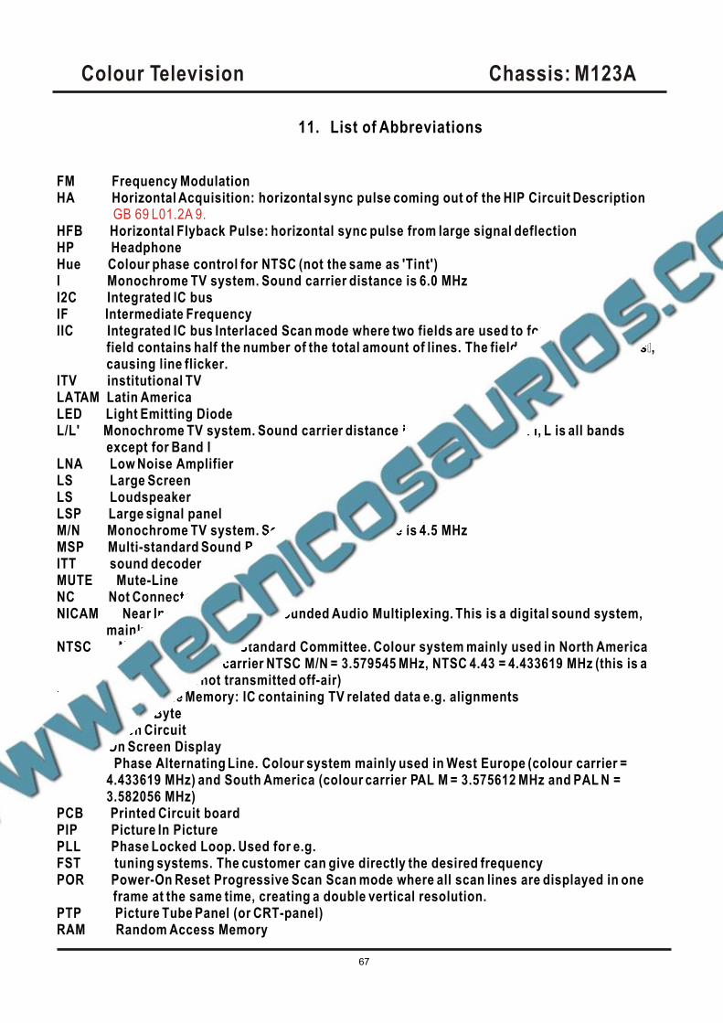
Colour Television Chassis: M123A
67
FM Frequency ModulationHA Horizontal Acquisition: horizontal sync pulse coming out of the HIP Circuit Description
HFB Horizontal Flyback Pulse: horizontal sync pulse from large signal deflectionHP HeadphoneHue Colour phase control for NTSC (not the same as 'Tint') I Monochrome TV system. Sound carrier distance is 6.0 MHzI2C Integrated IC busIF Intermediate FrequencyIIC Integrated IC bus Interlaced Scan mode where two fields are used to form one frame. Each
field contains half the number of the total amount of lines. The fields are written in “pairs”, causing line flicker.
ITV institutional TVLATAM Latin AmericaLED Light Emitting DiodeL/L' Monochrome TV system. Sound carrier distance is 6.5 MHz. L' is Band I, L is all bands
except for Band ILNA Low Noise AmplifierLS Large ScreenLS LoudspeakerLSP Large signal panelM/N Monochrome TV system. Sound carrier distance is 4.5 MHzMSP Multi-standard Sound Processor:ITT sound decoder MUTE Mute-LineNC Not ConnectedNICAM Near Instantaneous Compounded Audio Multiplexing. This is a digital sound system,
mainly used in Europe.NTSC National Television Standard Committee. Colour system mainly used in North America
and Japan. Colour carrier NTSC M/N = 3.579545 MHz, NTSC 4.43 = 4.433619 MHz (this is a VCR norm, it is not transmitted off-air)
NVM Non Volatile Memory: IC containing TV related data e.g. alignmentsOB Option ByteOC Open CircuitOSD On Screen DisplayPAL Phase Alternating Line. Colour system mainly used in West Europe (colour carrier =
4.433619 MHz) and South America (colour carrier PAL M = 3.575612 MHz and PAL N =3.582056 MHz)
PCB Printed Circuit boardPIP Picture In PicturePLL Phase Locked Loop. Used for e.g.FST tuning systems. The customer can give directly the desired frequencyPOR Power-On Reset Progressive Scan Scan mode where all scan lines are displayed in one frame at the same time, creating a double vertical resolution.PTP Picture Tube Panel (or CRT-panel)RAM Random Access Memory
GB 69 L01.2A 9.
11. List of Abbreviations
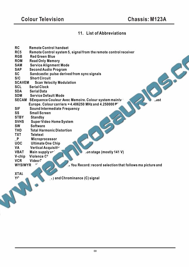
Colour Television Chassis: M123A
68
RC Remote Control handsetRC5 Remote Control system 5, signal from the remote control receiverRGB Red Green BlueROM Read Only MemorySAM Service Alignment ModeSAP Second Audio ProgramSC Sandcastle: pulse derived from sync signalsS/C Short CircuitSCAVEM Scan Velocity ModulationSCL Serial ClockSDA Serial DataSDM Service Default ModeSECAM SEequence Couleur Avec Memoire. Colour system mainly used in France and East Europe. Colour carriers = 4.406250 MHz and 4.250000 MHzSIF Sound Intermediate FrequencySS Small ScreenSTBY StandbySVHS Super Video Home SystemSW SoftwareTHD Total Harmonic DistortionTXT Teletext_P MicroprocessorUOC Ultimate One ChipVA Vertical AcquisitionVBAT Main supply voltage for the deflection stage (mostly 141 V)V-chip Violence ChipVCR Video Cassette RecorderWYSIWYR What You See Is What You Record: record selection that follows ma picture and soundXTAL Quartz crystalYC Luminance (Y) and Chrominance (C) signal
11. List of Abbreviations
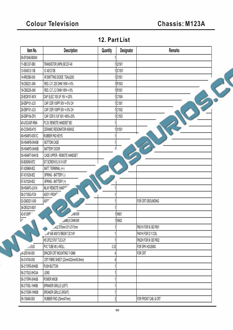
Item No. Description Quantity Designator Remarks
06-0F3046-B004X 1
11-0BC337-0BX TRANSISTOR (NPN) BC337-40 1 Q1501
13-00AS12-13B IC AS1213B 1 IC1501
14-IRE05B-XX0 IR EMITTING DIODE TSAL6200 1 D1501
18-CB0221-JNX RES. C.F. 220 OHM 1/6W +/-5% 1 R1503
18-CB0229-JNX RES. C.F. 2.2 OHM 1/6W +/-5% 1 R1501
25-BCB101-M1X CAP. ELEC 100 UF 16V +/-20% 1 C1504
26-EBP101-JCX CAP. CER 100PF 50V +/-5% CH 1 C1501
26-EBP101-JCX CAP. CER 100PF 50V +/-5% CH 1 C1502
26-EBP104-ZFX CAP. CER 0.1UF 50V +80%/-20% 1 C1503
40-UOCASF-RMA P.C.B. REMOTE HANDSET BD 1
45-COS455-KY0 CERAMIC RESONATOR 455KHZ 1 X1501
49-HS46F0-00X1C RUBBER PAD KEYS 1
55-HS46FB-0HA5B BOTTOM CASE 1
55-HS46FD-0HA5B BATTERY DOOR 1
55-HS46FT-0HA1B CASE UPPER - REMOTE HANDSET 1
63-B26060-BT2 S/T SCREW B 2.6 X 6 BT 1
67-X26968-0E2 BATT. TERMINAL (+/-) 1
67-X31028-0E2 SPRING - BATTERY (-) 1
67-X31029-0E2 SPRING - BATTERY (+) 1
58-HS46F3-JUI1A INLAY REMOTE HANDSET 1
08-2170SG-FCN ASS'Y- FRONT CABINET 1
02-GND021-XX0 ASS"Y - CRT GND WIRE&HOUSE 1 FOR CRT GROUNDING
36-DEG210-BX1 DEGAUSSING COIL 2500mm 1
42-61308E-XX0 SPEAKER (58MMX128MM) 8 OHM 6W 1 W601
42-61308E-XX0 SPEAKER (58MMX128MM) 8 OHM 6W 1 W602
46-14026H-02X HS 2P 2468#22 570mm S11-2Y/7mm 1 P601H FOR M. BD P601
46-27688H-04X HS 4P A/B 400/13 RBGW TJC1/4Y 1 P401H FOR D.Y COIL
46-35196H-02X HS 2P22 570/7 TJC3-2Y 1 P602H FOR M. BD P602
54-113970-0U0 PVC TUBE #5 L=ROLL 0.32 FOR SPK HOUSING
54-205140-000 SPACER CRT MOUNTING T=2MM 4 FOR CRT
54-314740-0X0 CRT FIBRE SHEET (22mmX22mmX0.8mm) 4
56-2170FB-0HA5B PUSH BUTTON 1
56-2170LE-0HCAA LENS 1
56-2170PK-0HA5B POWER KNOB 1
56-2170SL-1HN5B SPRAKER GRILLE (LEFT) 1
56-2170SR-1HN5B SPEAKER GRILLE (RIGHT) 1
59-130460-00X RUBBER PAD (25mmX7mm) 2 FOR FRONT CAB. & CRT
Colour Television Chassis: M123A
69
12. Part List
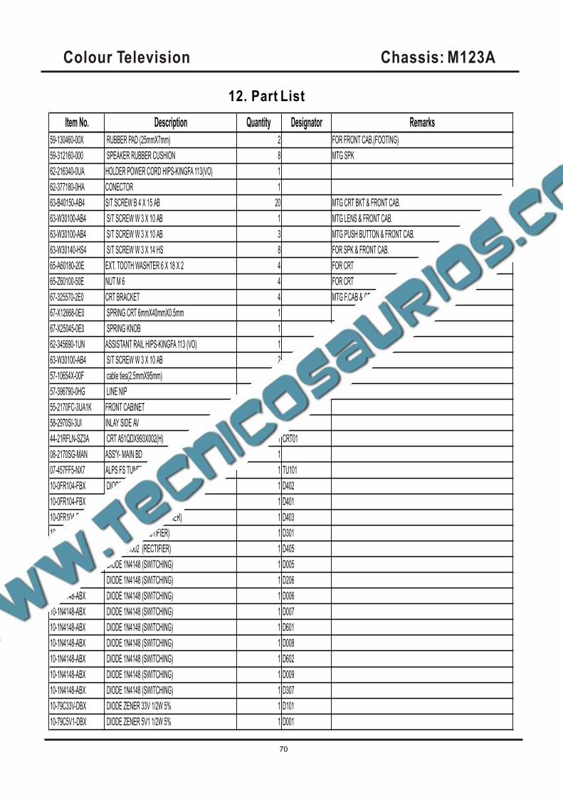
Item No. Description Quantity Designator Remarks
59-130460-00X RUBBER PAD (25mmX7mm) 2 FOR FRONT CAB.(FOOTING)
59-312160-000 SPEAKER RUBBER CUSHION 8 MTG SPK
62-216340-0UA HOLDER POWER CORD HIPS-KINGFA 113(VO) 1
62-377180-0HA CONECTOR 1
63-B40150-AB4 S/T SCREW B 4 X 15 AB 20 MTG CRT BKT & FRONT CAB.
63-W30100-AB4 S/T SCREW W 3 X 10 AB 1 MTG LENS & FRONT CAB.
63-W30100-AB4 S/T SCREW W 3 X 10 AB 3 MTG PUSH BUTTON & FRONT CAB.
63-W30140-HS4 S/T SCREW W 3 X 14 HS 8 FOR SPK & FRONT CAB.
65-A60180-20E EXT. TOOTH WASHTER 6 X 18 X 2 4 FOR CRT
65-Z60100-50E NUT M 6 4 FOR CRT
67-325570-2E0 CRT BRACKET 4 MTG F.CAB & CRT
67-X12668-0E0 SPRING CRT 6mmX40mmX0.5mm 1
67-X25045-0E0 SPRING KNOB 1
62-345690-1UN ASSISTANT RAIL HIPS-KINGFA 113 (VO) 1
63-W30100-AB4 S/T SCREW W 3 X 10 AB 2 ••••••••••••
57-10654X-00F cable ties(2.5mmX95mm) 6
57-396790-0HG LINE NIP 1
55-2170FC-3UA1K FRONT CABINET 1
58-2970SI-3UI INLAY SIDE AV 1
44-21RFLN-SZ3A CRT A51QDX993X002(H) 1 CRT01
08-2170SG-MAN ASS'Y- MAIN BD 1
07-457FF5-NX7 ALPS FS TUNER TEDH9-249A 1 TU101
10-0FR104-FBX DIODE FR104 (FAST RECTIFIER) 1 D402
10-0FR104-FBX DIODE FR104 (FAST RECTIFIER) 1 D401
10-0FR104-FBX DIODE FR104 (FAST RECTIFIER) 1 D403
10-1N4001-EBX DIODE 1N4001 (RECTIFIER) 1 D301
10-1N4002-EBX DIODE 1N4002 (RECTIFIER) 1 D405
10-1N4148-ABX DIODE 1N4148 (SWITCHING) 1 D005
10-1N4148-ABX DIODE 1N4148 (SWITCHING) 1 D206
10-1N4148-ABX DIODE 1N4148 (SWITCHING) 1 D006
10-1N4148-ABX DIODE 1N4148 (SWITCHING) 1 D007
10-1N4148-ABX DIODE 1N4148 (SWITCHING) 1 D601
10-1N4148-ABX DIODE 1N4148 (SWITCHING) 1 D008
10-1N4148-ABX DIODE 1N4148 (SWITCHING) 1 D602
10-1N4148-ABX DIODE 1N4148 (SWITCHING) 1 D009
10-1N4148-ABX DIODE 1N4148 (SWITCHING) 1 D307
10-79C33V-DBX DIODE ZENER 33V 1/2W 5% 1 D101
10-79C5V1-DBX DIODE ZENER 5V1 1/2W 5% 1 D001
Colour Television Chassis: M123A
70
12. Part List
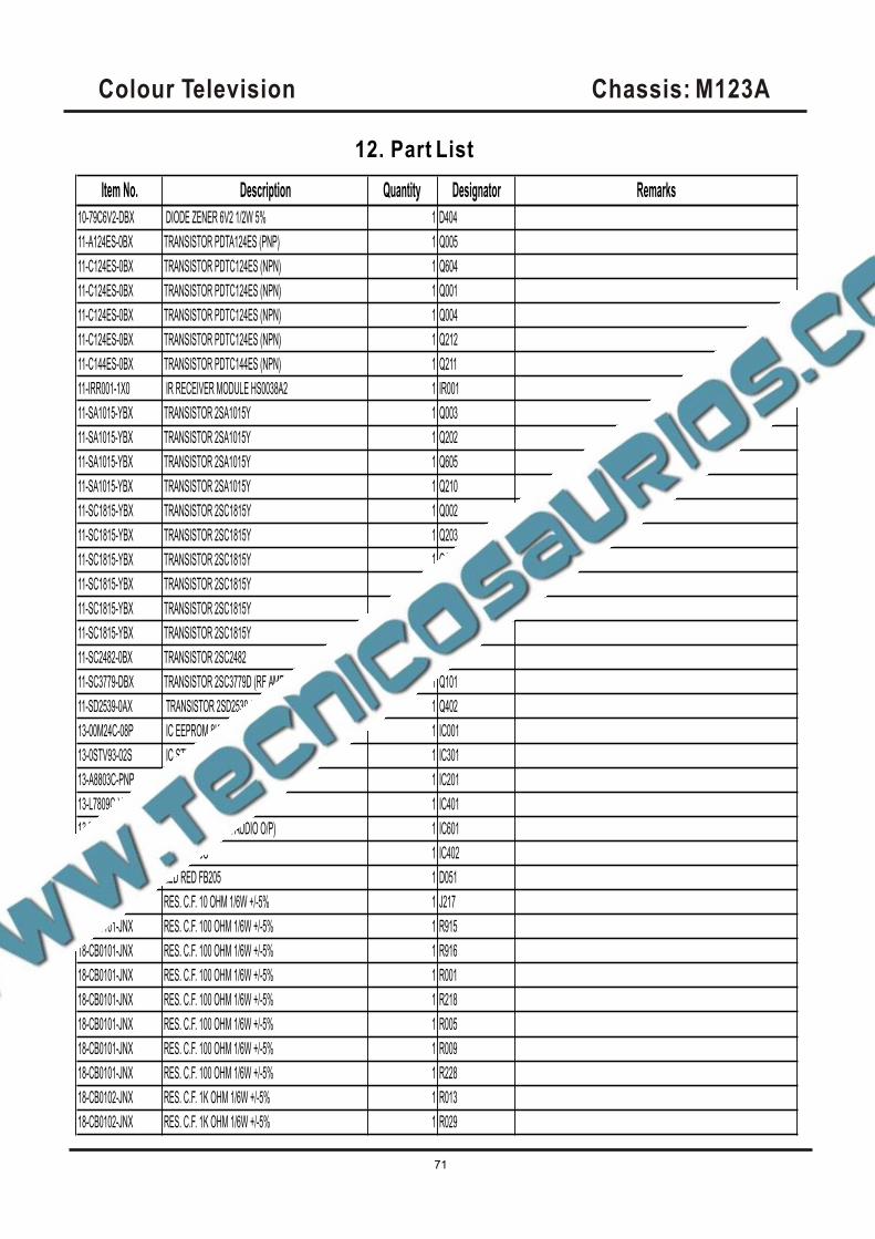
Item No. Description Quantity Designator Remarks
10-79C6V2-DBX DIODE ZENER 6V2 1/2W 5% 1 D404
11-A124ES-0BX TRANSISTOR PDTA124ES (PNP) 1 Q005
11-C124ES-0BX TRANSISTOR PDTC124ES (NPN) 1 Q604
11-C124ES-0BX TRANSISTOR PDTC124ES (NPN) 1 Q001
11-C124ES-0BX TRANSISTOR PDTC124ES (NPN) 1 Q004
11-C124ES-0BX TRANSISTOR PDTC124ES (NPN) 1 Q212
11-C144ES-0BX TRANSISTOR PDTC144ES (NPN) 1 Q211
11-IRR001-1X0 IR RECEIVER MODULE HS0038A2 1 IR001
11-SA1015-YBX TRANSISTOR 2SA1015Y 1 Q003
11-SA1015-YBX TRANSISTOR 2SA1015Y 1 Q202
11-SA1015-YBX TRANSISTOR 2SA1015Y 1 Q605
11-SA1015-YBX TRANSISTOR 2SA1015Y 1 Q210
11-SC1815-YBX TRANSISTOR 2SC1815Y 1 Q002
11-SC1815-YBX TRANSISTOR 2SC1815Y 1 Q203
11-SC1815-YBX TRANSISTOR 2SC1815Y 1 Q208
11-SC1815-YBX TRANSISTOR 2SC1815Y 1 Q209
11-SC1815-YBX TRANSISTOR 2SC1815Y 1 Q404
11-SC1815-YBX TRANSISTOR 2SC1815Y 1 Q905
11-SC2482-0BX TRANSISTOR 2SC2482 1 Q401
11-SC3779-DBX TRANSISTOR 2SC3779D (RF AMPL) 1 Q101
11-SD2539-0AX TRANSISTOR 2SD2539 (HORIZ O/P) 1 Q402
13-00M24C-08P IC EEPROM 8K M24C08 1 IC001
13-0STV93-02S IC STV9302 1 IC301
13-A8803C-PNP IC TMPA8803CPN 1 IC201
13-L7809C-VAP IC L7809CV 1 IC401
13-TDA705-7AS IC TDA7057AQ (R/L AUDIO O/P) 1 IC601
13-UA7805-C0S IC UA7805C 1 IC402
14-LED05R-XX1 LED RED FB205 1 D051
18-CB0100-JNX RES. C.F. 10 OHM 1/6W +/-5% 1 J217
18-CB0101-JNX RES. C.F. 100 OHM 1/6W +/-5% 1 R915
18-CB0101-JNX RES. C.F. 100 OHM 1/6W +/-5% 1 R916
18-CB0101-JNX RES. C.F. 100 OHM 1/6W +/-5% 1 R001
18-CB0101-JNX RES. C.F. 100 OHM 1/6W +/-5% 1 R218
18-CB0101-JNX RES. C.F. 100 OHM 1/6W +/-5% 1 R005
18-CB0101-JNX RES. C.F. 100 OHM 1/6W +/-5% 1 R009
18-CB0101-JNX RES. C.F. 100 OHM 1/6W +/-5% 1 R228
18-CB0102-JNX RES. C.F. 1K OHM 1/6W +/-5% 1 R013
18-CB0102-JNX RES. C.F. 1K OHM 1/6W +/-5% 1 R029
Colour Television Chassis: M123A
71
12. Part List

Item No. Description Quantity Designator Remarks
18-CB0102-JNX RES. C.F. 1K OHM 1/6W +/-5% 1 R051
18-CB0102-JNX RES. C.F. 1K OHM 1/6W +/-5% 1 R116
18-CB0102-JNX RES. C.F. 1K OHM 1/6W +/-5% 1 R234
18-CB0102-JNX RES. C.F. 1K OHM 1/6W +/-5% 1 R415
18-CB0102-JNX RES. C.F. 1K OHM 1/6W +/-5% 1 R924
18-CB0103-JNX RES. C.F. 10K OHM 1/6W +/-5% 1 R003
18-CB0103-JNX RES. C.F. 10K OHM 1/6W +/-5% 1 R004
18-CB0103-JNX RES. C.F. 10K OHM 1/6W +/-5% 1 R006
18-CB0103-JNX RES. C.F. 10K OHM 1/6W +/-5% 1 R010
18-CB0103-JNX RES. C.F. 10K OHM 1/6W +/-5% 1 R011
18-CB0103-JNX RES. C.F. 10K OHM 1/6W +/-5% 1 R012
18-CB0103-JNX RES. C.F. 10K OHM 1/6W +/-5% 1 R025
18-CB0103-JNX RES. C.F. 10K OHM 1/6W +/-5% 1 R030
18-CB0103-JNX RES. C.F. 10K OHM 1/6W +/-5% 1 R042
18-CB0103-JNX RES. C.F. 10K OHM 1/6W +/-5% 1 R043
18-CB0103-JNX RES. C.F. 10K OHM 1/6W +/-5% 1 R047
18-CB0103-JNX RES. C.F. 10K OHM 1/6W +/-5% 1 R050
18-CB0103-JNX RES. C.F. 10K OHM 1/6W +/-5% 1 R406
18-CB0104-JNX RES. C.F. 100K OHM 1/6W +/-5% 1 R031
18-CB0121-JNX RES. C.F. 120 OHM 1/6W +/-5% 1 R227
18-CB0123-JNX RES. C.F. 12k OHM 1/6W +/-5% 1 R212
18-CB0151-JNX RES. C.F. 150 OHM 1/6W +/-5% 1 R115
18-CB0151-JNX RES. C.F. 150 OHM 1/6W +/-5% 1 R117
18-CB0152-JNX RES. C.F. 1.5k OHM 1/6W +/-5% 1 R007
18-CB0152-JNX RES. C.F. 1.5k OHM 1/6W +/-5% 1 R020
18-CB0153-JNX RES. C.F. 15k OHM 1/6W +/-5% 1 R315
18-CB0182-JNX RES. C.F. 1.8K OHM 1/6W +/-5% 1 R021
18-CB0221-JNX RES. C.F. 220 OHM 1/6W +/-5% 1 R201
18-CB0221-JNX RES. C.F. 220 OHM 1/6W +/-5% 1 R202
18-CB0221-JNX RES. C.F. 220 OHM 1/6W +/-5% 1 R203
18-CB0221-JNX RES. C.F. 220 OHM 1/6W +/-5% 1 R220
18-CB0221-JNX RES. C.F. 220 OHM 1/6W +/-5% 1 R238
18-CB0221-JNX RES. C.F. 220 OHM 1/6W +/-5% 1 R401
18-CB0222-JNX RES. C.F. 2.2k OHM 1/6W +/-5% 1 R055
18-CB0222-JNX RES. C.F. 2.2k OHM 1/6W +/-5% 1 R044
18-CB0223-JNX RES. C.F. 22k OHM 1/6W +/-5% 1 R913
18-CB0223-JNX RES. C.F. 22k OHM 1/6W +/-5% 1 R215
18-CB0223-JNX RES. C.F. 22k OHM 1/6W +/-5% 1 R912
Colour Television Chassis: M123A
72
12. Part List

Item No. Description Quantity Designator Remarks
18-CB0224-JNX RES. C.F. 220k OHM 1/6W +/-5% 1 R206
18-CB0271-JNX RES. C.F. 270 OHM 1/6W +/-5% 1 R217
18-CB0271-JNX RES. C.F. 270 OHM 1/6W +/-5% 1 R233
18-CB0272-JNX RES. C.F. 2.7k OHM 1/6W +/-5% 1 R022
18-CB0303-JNX RES. C.F. 30K OHM 1/6W +/-5% 1 R205
18-CB0331-JNX RES. C.F. 330 OHM 1/6W +/-5% 1 R219
18-CB0332-JNX RES. C.F. 3.3k OHM 1/6W +/-5% 1 R218A
18-CB0332-JNX RES. C.F. 3.3k OHM 1/6W +/-5% 1 R046
18-CB0333-JNX RES. C.F. 33K OHM 1/6W +/-5% 1 R602
18-CB0104-JNX RES. C.F. 100K OHM 1/6W +/-5% 1 R232
18-CB0392-JNX RES. C.F. 3.9K OHM 1/6W +/-5% 1 R213
18-CB0392-JNX RES. C.F. 3.9K OHM 1/6W +/-5% 1 R214
18-CB0432-JNX RES. C.F. 4.3K OHM 1/6W +/-5% 1 R023
18-CB0433-JNX RES. C.F. 43k OHM 1/6W +/-5% 1 R026
18-CB0470-JNX RES. C.F. 47 OHM 1/6W +/-5% 1 R002
18-CB0470-JNX RES. C.F. 47 OHM 1/6W +/-5% 1 R018
18-CB0471-JNX RES. C.F. 470 OHM 1/6W +/-5% 1 R119
18-CB0471-JNX RES. C.F. 470 OHM 1/6W +/-5% 1 R208
18-CB0472-JNX RES. C.F. 4.7k OHM 1/6W +/-5% 1 R016
18-CB0472-JNX RES. C.F. 4.7k OHM 1/6W +/-5% 1 R015
18-CB0473-JNX RES. C.F. 47K OHM 1/6W +/-5% 1 R216
18-CB0473-JNX RES. C.F. 47K OHM 1/6W +/-5% 1 R245
18-CB0560-JNX RES. C.F. 56 OHM 1/6W +/-5% 1 R114
18-CB0561-JNX RES. C.F. 560 OHM 1/6W +/-5% 1 R209
18-CB0564-JNX RES. C.F. 560K OHM 1/6W +/-5% 1 R210
18-CB0681-JNX RES. C.F. 680 OHM 1/6W +/-5% 1 R028
18-CB0682-JNX RES. C.F. 6.8K OHM 1/6W +/-5% 1 R024
18-CB0683-JNX RES. C.F. 68K OHM 1/6W +/-5% 1 R211
18-CB0751-JNX RES. C.F. 750 OHM 1/6W +/-5% 1 R008
18-CB0821-JNX RES. C.F. 820 OHM 1/6W +/-5% 1 R118
18-CB0822-JNX RES. C.F. 8.2K OHM 1/6W +/-5% 1 R237
18-CB0822-JNX RES. C.F. 8.2K OHM 1/6W +/-5% 1 R606
18-CD0100-JNX RES. C.F. 10 OHM 1/4W +/-5% 1 R027
18-CE0479-JNX RES. C.F. 4.7 OHM 1/2W +/-5% 1 R640
18-EF0109-JGX RES. FUS. 1 OHM 1W +/-5% (LS) 1 R403
18-EF0109-JGX RES. FUS. 1 OHM 1W +/-5% (LS) 1 R405
18-EF0109-JGX RES. FUS. 1 OHM 1W +/-5% (LS) 1 R418
18-EF0109-JGX RES. FUS. 1 OHM 1W +/-5% (LS) 1 R409
Colour Television Chassis: M123A
73
12. Part List

Item No. Description Quantity Designator Remarks
18-FF0103-JGX RES. M.O. 10k OHM 1W +/-5% 1 R410
18-FF0122-JGX RES. M.O. 1.2k OHM 1W +/-5% 1 R411
18-FF0123-JGX RES. M.O. 12k OHM 1W +/-5% 1 R408
18-FF0129-JGX RES. M.O. 1.2 OHM 1W +/-5% 1 R304
18-FF0221-JGX RES. M.O. 220 OHM 1W +/-5% 1 R336
18-EF0229-JGX RES. FUS. 2.2 OHM 1W +/-5% 1 R420
18-FG0153-JHX RES. M.O. 15k OHM 2W +/-5% 1 R404
18-FG0229-JHX RES. M.O. 2.2 OHM 2W +/-5% 1 R309
18-GJ0332-JUX1 RES.C.C.5W 3.3KOHM +/-5% 1 R402
18-RG0228-JHX RES. WIRE ROUND 0.22 OHM 2W +/-5% 1 R620
25-BCA102-M1X CAP. ELEC 1000 UF 16V +/-20% 1 C232
25-BCB100-M1X CAP. ELEC 10 UF 16V +/-20% 1 C004
25-BCB100-M1X CAP. ELEC 10 UF 16V +/-20% 1 C220
25-BCB100-M1X CAP. ELEC 10 UF 16V +/-20% 1 C023
25-BCB100-M1X CAP. ELEC 10 UF 16V +/-20% 1 C227
25-BCB100-M1X CAP. ELEC 10 UF 16V +/-20% 1 C231
25-BCB100-M1X CAP. ELEC 10 UF 16V +/-20% 1 C907
25-BCB100-M1X CAP. ELEC 10 UF 16V +/-20% 1 C603
25-BCB101-M1X CAP. ELEC 100 UF 16V +/-20% 1 C016
25-BCB101-M1X CAP. ELEC 100 UF 16V +/-20% 1 C240
25-BCB101-M1X CAP. ELEC 100 UF 16V +/-20% 1 C605
25-BCB101-M1X CAP. ELEC 100 UF 16V +/-20% 1 C211
25-BCB101-M1X CAP. ELEC 100 UF 16V +/-20% 1 C101
25-BCB220-M1X CAP. ELEC 22 UF 16V +/-20% 1 C015
25-BCB221-M1X CAP. ELEC 220 UF 16V +/-20% 1 C009
25-BCB470-M1X CAP. ELEC 47 UF 16V +/-20% 1 C423
25-BCB470-M1X CAP. ELEC 47 UF 16V +/-20% 1 C202
25-BCB470-M1X CAP. ELEC 47 UF 16V +/-20% 1 C082
25-BDA471-M1X CAP. ELEC 470 UF 25V +/-20% 1 C217
25-BDA471-M1X CAP. ELEC 470 UF 25V +/-20% 1 C604
25-BDA471-M1X CAP. ELEC 470 UF 25V +/-20% 1 C415
25-BDB221-M1X CAP. ELEC 220 UF 25V +/-20% 1 C301
25-BEA102-M1X CAP. ELEC 1000 UF 35V +/-20% 1 C413
25-BEB101-M1X CAP. ELEC 100 UF 35V +/-20% 1 C302
25-BFA220-M1X CAP. ELEC 22 UF 50V +/-20% 1 C106
25-BFB109-M1X CAP. ELEC 1 UF 50V +/-20% 1 C208
25-BFB109-M1X CAP. ELEC 1 UF 50V +/-20% 1 C203
25-BFB109-M1X CAP. ELEC 1 UF 50V +/-20% 1 C008A
Colour Television Chassis: M123A
74
12. Part List
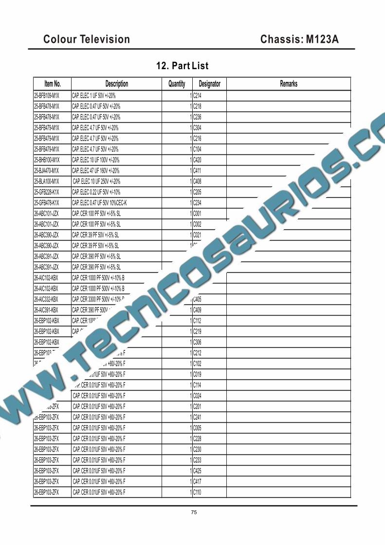
Item No. Description Quantity Designator Remarks
25-BFB109-M1X CAP. ELEC 1 UF 50V +/-20% 1 C214
25-BFB478-M1X CAP. ELEC 0.47 UF 50V +/-20% 1 C218
25-BFB478-M1X CAP. ELEC 0.47 UF 50V +/-20% 1 C236
25-BFB479-M1X CAP. ELEC 4.7 UF 50V +/-20% 1 C304
25-BFB479-M1X CAP. ELEC 4.7 UF 50V +/-20% 1 C216
25-BFB479-M1X CAP. ELEC 4.7 UF 50V +/-20% 1 C104
25-BHB100-M1X CAP. ELEC 10 UF 100V +/-20% 1 C420
25-BJA470-M1X CAP. ELEC 47 UF 160V +/-20% 1 C411
25-BLA100-M1X CAP. ELEC 10 UF 250V +/-20% 1 C408
25-GFB228-K1X CAP. ELEC 0.22 UF 50V +/-10% 1 C205
25-GFB478-K1X CAP. ELEC 0.47 UF 50V 10%CEC-K 1 C234
26-ABC101-JZX CAP. CER 100 PF 50V +/-5% SL 1 C001
26-ABC101-JZX CAP. CER 100 PF 50V +/-5% SL 1 C002
26-ABC390-JZX CAP. CER 39 PF 50V +/-5% SL 1 C021
26-ABC390-JZX CAP. CER 39 PF 50V +/-5% SL 1 C022
26-ABC391-JZX CAP. CER 390 PF 50V +/-5% SL 1 C412
26-ABC391-JZX CAP. CER 390 PF 50V +/-5% SL 1 C403
26-AIC102-KBX CAP. CER 1000 PF 500V +/-10% B 1 C401
26-AIC102-KBX CAP. CER 1000 PF 500V +/-10% B 1 C404
26-AIC332-KBX CAP. CER 3300 PF 500V +/-10% B 1 C405
26-AIC391-KBX CAP. CER 390 PF 500V +/-10% B 1 C409
26-EBP102-KBX CAP. CER 1000 PF 50V +/-10% B 1 C112
26-EBP102-KBX CAP. CER 1000 PF 50V +/-10% B 1 C219
26-EBP102-KBX CAP. CER 1000 PF 50V +/-10% B 1 C306
26-EBP103-ZFX CAP. CER 0.01UF 50V +80/-20% F 1 C212
26-EBP103-ZFX CAP. CER 0.01UF 50V +80/-20% F 1 C102
26-EBP103-ZFX CAP. CER 0.01UF 50V +80/-20% F 1 C019
26-EBP103-ZFX CAP. CER 0.01UF 50V +80/-20% F 1 C114
26-EBP103-ZFX CAP. CER 0.01UF 50V +80/-20% F 1 C024
26-EBP103-ZFX CAP. CER 0.01UF 50V +80/-20% F 1 C201
26-EBP103-ZFX CAP. CER 0.01UF 50V +80/-20% F 1 C241
26-EBP103-ZFX CAP. CER 0.01UF 50V +80/-20% F 1 C005
26-EBP103-ZFX CAP. CER 0.01UF 50V +80/-20% F 1 C228
26-EBP103-ZFX CAP. CER 0.01UF 50V +80/-20% F 1 C230
26-EBP103-ZFX CAP. CER 0.01UF 50V +80/-20% F 1 C233
26-EBP103-ZFX CAP. CER 0.01UF 50V +80/-20% F 1 C425
26-EBP103-ZFX CAP. CER 0.01UF 50V +80/-20% F 1 C417
26-EBP103-ZFX CAP. CER 0.01UF 50V +80/-20% F 1 C110
Colour Television Chassis: M123A
75
12. Part List
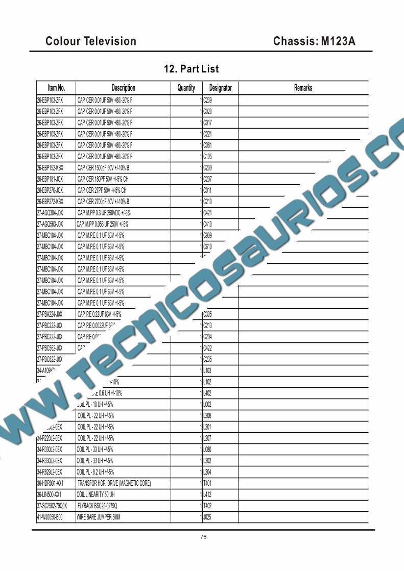
Item No. Description Quantity Designator Remarks
26-EBP103-ZFX CAP. CER 0.01UF 50V +80/-20% F 1 C239
26-EBP103-ZFX CAP. CER 0.01UF 50V +80/-20% F 1 C020
26-EBP103-ZFX CAP. CER 0.01UF 50V +80/-20% F 1 C017
26-EBP103-ZFX CAP. CER 0.01UF 50V +80/-20% F 1 C221
26-EBP103-ZFX CAP. CER 0.01UF 50V +80/-20% F 1 C081
26-EBP103-ZFX CAP. CER 0.01UF 50V +80/-20% F 1 C105
26-EBP152-KBX CAP. CER 1500pF 50V +/-10% B 1 C209
26-EBP181-JCX CAP. CER 180PF 50V +/-5% CH 1 C207
26-EBP270-JCX CAP. CER 27PF 50V +/-5% CH 1 C011
26-EBP272-KBX CAP. CER 2700pF 50V +/-10% B 1 C210
27-AGQ304-J0X CAP. M.PP 0.3 UF 250VDC +/-5% 1 C421
27-AGQ563-J0X CAP. M.PP 0.056 UF 250V +/-5% 1 C410
27-MBC104-J0X CAP. M.P.E 0.1 UF 63V +/-5% 1 C909
27-MBC104-J0X CAP. M.P.E 0.1 UF 63V +/-5% 1 C610
27-MBC104-J0X CAP. M.P.E 0.1 UF 63V +/-5% 1 C911
27-MBC104-J0X CAP. M.P.E 0.1 UF 63V +/-5% 1 C912
27-MBC104-J0X CAP. M.P.E 0.1 UF 63V +/-5% 1 C910
27-MBC104-J0X CAP. M.P.E 0.1 UF 63V +/-5% 1 C242
27-MBC104-J0X CAP. M.P.E 0.1 UF 63V +/-5% 1 C309
27-PBA224-J0X CAP. P.E 0.22UF 63V +/-5% 1 C305
27-PBC222-J0X CAP. P.E 0.0022UF 63V +/-5% 1 C213
27-PBC222-J0X CAP. P.E 0.0022UF 63V +/-5% 1 C204
27-PBC562-J0X CAP. P.E 0.0056UF 63V +/-5% 1 C422
27-PBC822-J0X CAP. P.E 0.0082UF 63V +/-5% 1 C235
34-A109K0-1IX COIL CHOKE 1 UH +/-10% 1 L103
34-A109K0-1IX COIL CHOKE 1 UH +/-10% 1 L102
34-A608K6-1BX COIL CHOKE 0.6 UH +/-10% 1 L402
34-R100J2-0EX COIL PL - 10 UH +/-5% 1 L002
34-R220J2-0EX COIL PL - 22 UH +/-5% 1 L208
34-R220J2-0EX COIL PL - 22 UH +/-5% 1 L201
34-R220J2-0EX COIL PL - 22 UH +/-5% 1 L207
34-R330J2-0EX COIL PL - 33 UH +/-5% 1 L080
34-R330J2-0EX COIL PL - 33 UH +/-5% 1 L202
34-R829J2-0EX COIL PL - 8.2 UH +/-5% 1 L204
36-HDR001-AX1 TRANSFOR HOR. DRIVE (MAGNETIC CORE) 1 T401
36-LIN500-XX1 COIL LINEARITY 50 UH 1 L412
37-SC2502-79Q0X FLYBACK BSC25-0279Q 1 T402
41-WJ0050-B00 WIRE BARE JUMPER 5MM 1 J025
Colour Television Chassis: M123A
76
12. Part List

Item No. Description Quantity Designator Remarks
41-WJ0050-B00 WIRE BARE JUMPER 5MM 1 L101
41-WJ0060-B00 WIRE BARE JUMPER 6mm 1 J001
41-WJ0060-B00 WIRE BARE JUMPER 6mm 1 J009A
41-WJ0060-B00 WIRE BARE JUMPER 6mm 1 J015
41-WJ0060-B00 WIRE BARE JUMPER 6mm 1 J101
41-WJ0060-B00 WIRE BARE JUMPER 6mm 1 J203
41-WJ0060-B00 WIRE BARE JUMPER 6mm 1 J210
41-WJ0060-B00 WIRE BARE JUMPER 6mm 1 J211
41-WJ0060-B00 WIRE BARE JUMPER 6mm 1 R200
41-WJ0060-B00 WIRE BARE JUMPER 6mm 1 R204
41-WJ0060-B00 WIRE BARE JUMPER 6mm 1 R207
41-WJ0060-B00 WIRE BARE JUMPER 6mm 1 R249
41-WJ0065-B00 WIRE BARE JUMPER 6.5MM 1 J010
41-WJ0065-B00 WIRE BARE JUMPER 6.5MM 1 J208
41-WJ0065-B00 WIRE BARE JUMPER 6.5MM 1 J305
41-WJ0070-B00 WIRE BARE JUMPER 7MM 1 J217A
41-WJ0075-B00 WIRE BARE JUMPER 7.5MM 1 J303
41-WJ0075-B00 WIRE BARE JUMPER 7.5MM 1 J024
41-WJ0075-B00 WIRE BARE JUMPER 7.5MM 1 J205
41-WJ0075-B00 WIRE BARE JUMPER 7.5MM 1 J206
41-WJ0075-B00 WIRE BARE JUMPER 7.5MM 1 J207
41-WJ0075-B00 WIRE BARE JUMPER 7.5MM 1 J218
41-WJ0075-B00 WIRE BARE JUMPER 7.5MM 1 J602
41-WJ0075-B00 WIRE BARE JUMPER 7.5MM 1 J914
41-WJ0075-B00 WIRE BARE JUMPER 7.5MM 1 J225
41-WJ0075-B00 WIRE BARE JUMPER 7.5MM 1 J228
41-WJ0075-B00 WIRE BARE JUMPER 7.5MM 1 D838A
41-WJ0075-B00 WIRE BARE JUMPER 7.5MM 1 J215
41-WJ0075-B00 WIRE BARE JUMPER 7.5MM 1 J018
41-WJ0075-B00 WIRE BARE JUMPER 7.5MM 1 J928
41-WJ0080-B00 WIRE BARE JUMPER 8 MM 1 J011
41-WJ0080-B00 WIRE BARE JUMPER 8 MM 1 J012
41-WJ0080-B00 WIRE BARE JUMPER 8 MM 1 J108
41-WJ0085-B00 WIRE BARE JUMPER 8.5MM 1 J219
41-WJ0085-B00 WIRE BARE JUMPER 8.5MM 1 J302
41-WJ0090-B00 WIRE BARE JUMPER 9MM 1 J306
41-WJ0095-B00 WIRE BARE JUMPER 9.5MM 1 J601
41-WJ0095-B00 WIRE BARE JUMPER 9.5MM 1 J230
Colour Television Chassis: M123A
77
12. Part List
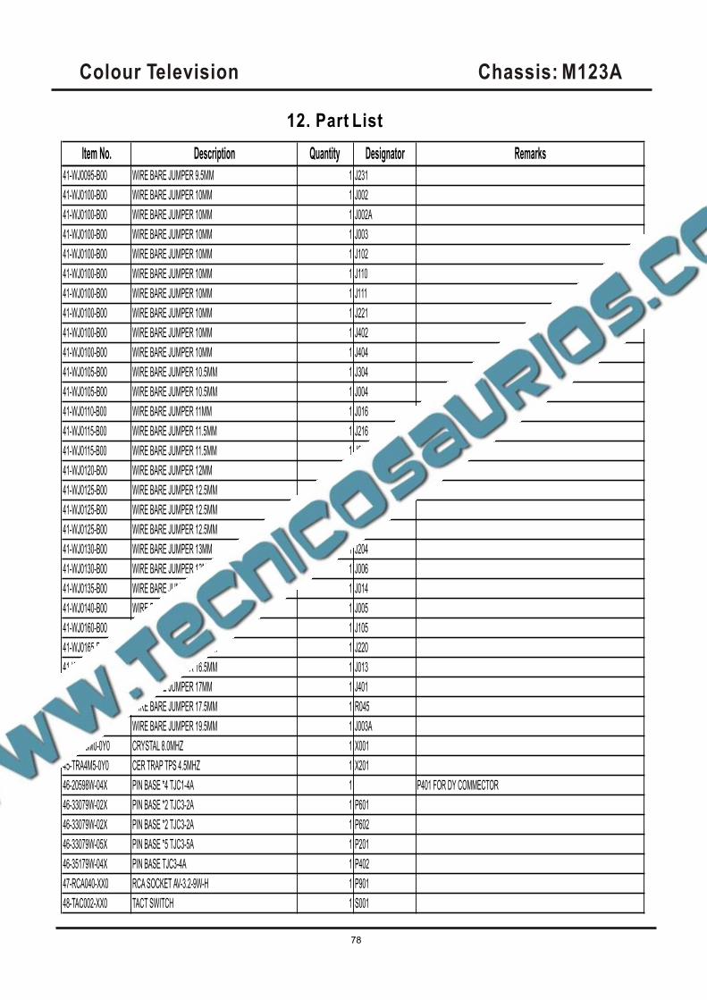
Item No. Description Quantity Designator Remarks
41-WJ0095-B00 WIRE BARE JUMPER 9.5MM 1 J231
41-WJ0100-B00 WIRE BARE JUMPER 10MM 1 J002
41-WJ0100-B00 WIRE BARE JUMPER 10MM 1 J002A
41-WJ0100-B00 WIRE BARE JUMPER 10MM 1 J003
41-WJ0100-B00 WIRE BARE JUMPER 10MM 1 J102
41-WJ0100-B00 WIRE BARE JUMPER 10MM 1 J110
41-WJ0100-B00 WIRE BARE JUMPER 10MM 1 J111
41-WJ0100-B00 WIRE BARE JUMPER 10MM 1 J221
41-WJ0100-B00 WIRE BARE JUMPER 10MM 1 J402
41-WJ0100-B00 WIRE BARE JUMPER 10MM 1 J404
41-WJ0105-B00 WIRE BARE JUMPER 10.5MM 1 J304
41-WJ0105-B00 WIRE BARE JUMPER 10.5MM 1 J004
41-WJ0110-B00 WIRE BARE JUMPER 11MM 1 J016
41-WJ0115-B00 WIRE BARE JUMPER 11.5MM 1 J216
41-WJ0115-B00 WIRE BARE JUMPER 11.5MM 1 J604
41-WJ0120-B00 WIRE BARE JUMPER 12MM 1 J232
41-WJ0125-B00 WIRE BARE JUMPER 12.5MM 1 J106
41-WJ0125-B00 WIRE BARE JUMPER 12.5MM 1 J924
41-WJ0125-B00 WIRE BARE JUMPER 12.5MM 1 R317
41-WJ0130-B00 WIRE BARE JUMPER 13MM 1 J204
41-WJ0130-B00 WIRE BARE JUMPER 13MM 1 J006
41-WJ0135-B00 WIRE BARE JUMPER 13.5MM 1 J014
41-WJ0140-B00 WIRE BARE JUMPER 14MM 1 J005
41-WJ0160-B00 WIRE BARE JUMPER 16MM 1 J105
41-WJ0165-B00 WIRE BARE JUMPER 16.5MM 1 J220
41-WJ0165-B00 WIRE BARE JUMPER 16.5MM 1 J013
41-WJ0170-B00 WIRE BARE JUMPER 17MM 1 J401
41-WJ0175-B00 WIRE BARE JUMPER 17.5MM 1 R045
41-WJ0195-B00 WIRE BARE JUMPER 19.5MM 1 J003A
45-OSC8M0-0Y0 CRYSTAL 8.0MHZ 1 X001
45-TRA4M5-0Y0 CER TRAP TPS 4.5MHZ 1 X201
46-20598W-04X PIN BASE *4 TJC1-4A 1 P401 FOR DY COMMECTOR
46-33079W-02X PIN BASE *2 TJC3-2A 1 P601
46-33079W-02X PIN BASE *2 TJC3-2A 1 P602
46-33079W-05X PIN BASE *5 TJC3-5A 1 P201
46-35179W-04X PIN BASE TJC3-4A 1 P402
47-RCA040-XX0 RCA SOCKET AV-3.2-9W-H 1 P901
48-TAC002-XX0 TACT SWITCH 1 S001
Colour Television Chassis: M123A
78
12. Part List
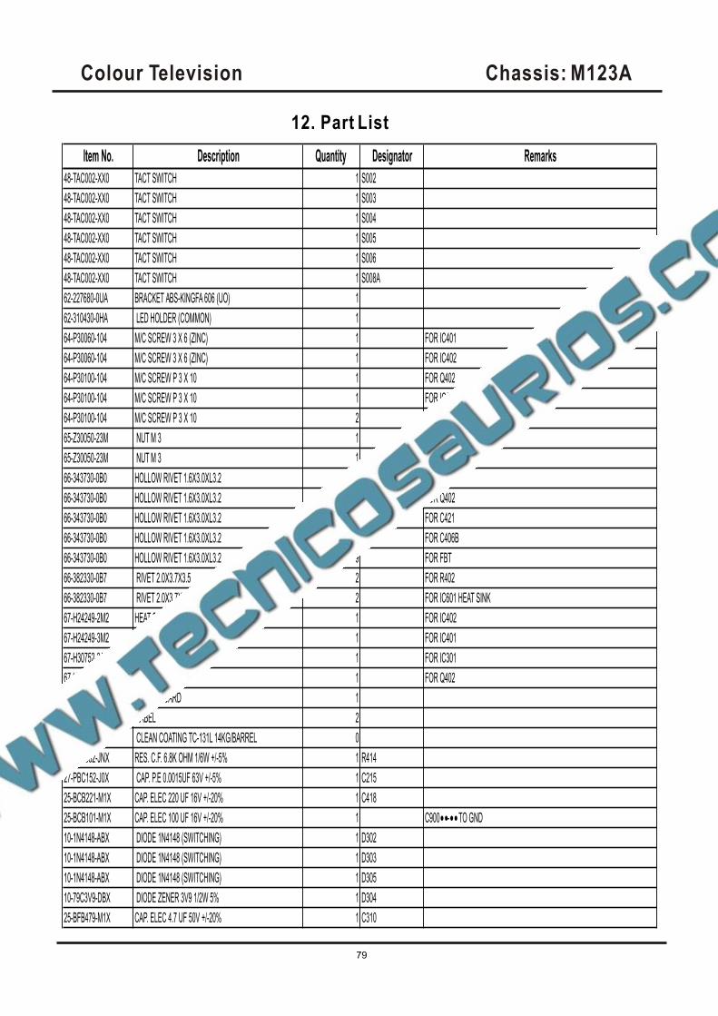
Item No. Description Quantity Designator Remarks
48-TAC002-XX0 TACT SWITCH 1 S002
48-TAC002-XX0 TACT SWITCH 1 S003
48-TAC002-XX0 TACT SWITCH 1 S004
48-TAC002-XX0 TACT SWITCH 1 S005
48-TAC002-XX0 TACT SWITCH 1 S006
48-TAC002-XX0 TACT SWITCH 1 S008A
62-227680-0UA BRACKET ABS-KINGFA 606 (UO) 1
62-310430-0HA LED HOLDER (COMMON) 1
64-P30060-104 M/C SCREW 3 X 6 (ZINC) 1 FOR IC401
64-P30060-104 M/C SCREW 3 X 6 (ZINC) 1 FOR IC402
64-P30100-104 M/C SCREW P 3 X 10 1 FOR Q402
64-P30100-104 M/C SCREW P 3 X 10 1 FOR IC301
64-P30100-104 M/C SCREW P 3 X 10 2 FOR IC601
65-Z30050-23M NUT M 3 1 FOR Q402
65-Z30050-23M NUT M 3 1 FOR IC301
66-343730-0B0 HOLLOW RIVET 1.6X3.0XL3.2 2 FOR L412
66-343730-0B0 HOLLOW RIVET 1.6X3.0XL3.2 3 FOR Q402
66-343730-0B0 HOLLOW RIVET 1.6X3.0XL3.2 2 FOR C421
66-343730-0B0 HOLLOW RIVET 1.6X3.0XL3.2 2 FOR C406B
66-343730-0B0 HOLLOW RIVET 1.6X3.0XL3.2 9 FOR FBT
66-382330-0B7 RIVET 2.0X3.7X3.5 2 FOR R402
66-382330-0B7 RIVET 2.0X3.7X3.5 2 FOR IC601 HEAT SINK
67-H24249-2M2 HEAT SINK 1 FOR IC402
67-H24249-3M2 HEAT SINK 1 FOR IC401
67-H30752-3A0 HEAT SINK 1 FOR IC301
67-H30752-3A0 HEAT SINK 1 FOR Q402
70-271510-00A SERVICE CARD 1
71-270870-0A9 LABEL 2
90-269080-ZU0 CLEAN COATING TC-131L 14KG/BARREL 0
18-CB0682-JNX RES. C.F. 6.8K OHM 1/6W +/-5% 1 R414
27-PBC152-J0X CAP. P.E 0.0015UF 63V +/-5% 1 C215
25-BCB221-M1X CAP. ELEC 220 UF 16V +/-20% 1 C418
25-BCB101-M1X CAP. ELEC 100 UF 16V +/-20% 1 C900••-•• TO GND
10-1N4148-ABX DIODE 1N4148 (SWITCHING) 1 D302
10-1N4148-ABX DIODE 1N4148 (SWITCHING) 1 D303
10-1N4148-ABX DIODE 1N4148 (SWITCHING) 1 D305
10-79C3V9-DBX DIODE ZENER 3V9 1/2W 5% 1 D304
25-BFB479-M1X CAP. ELEC 4.7 UF 50V +/-20% 1 C310
Colour Television Chassis: M123A
79
12. Part List
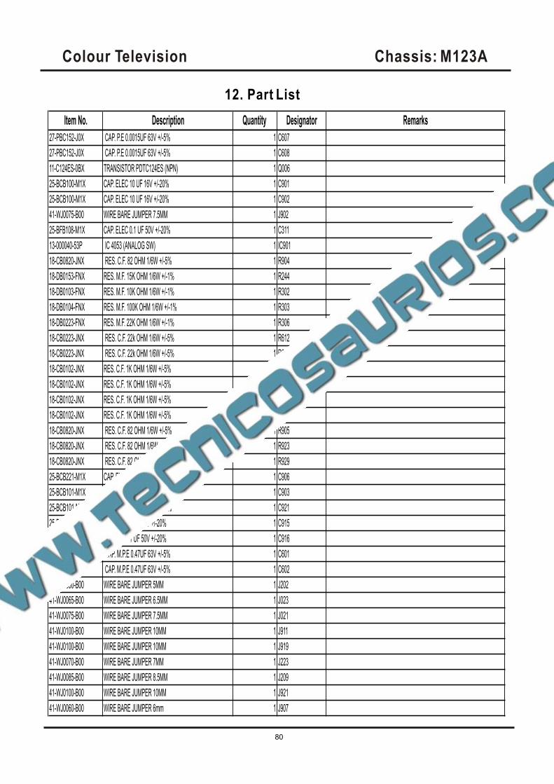
Item No. Description Quantity Designator Remarks
27-PBC152-J0X CAP. P.E 0.0015UF 63V +/-5% 1 C607
27-PBC152-J0X CAP. P.E 0.0015UF 63V +/-5% 1 C608
11-C124ES-0BX TRANSISTOR PDTC124ES (NPN) 1 Q006
25-BCB100-M1X CAP. ELEC 10 UF 16V +/-20% 1 C901
25-BCB100-M1X CAP. ELEC 10 UF 16V +/-20% 1 C902
41-WJ0075-B00 WIRE BARE JUMPER 7.5MM 1 J902
25-BFB108-M1X CAP. ELEC 0.1 UF 50V +/-20% 1 C311
13-000040-53P IC 4053 (ANALOG SW) 1 IC901
18-CB0820-JNX RES. C.F. 82 OHM 1/6W +/-5% 1 R904
18-DB0153-FNX RES. M.F. 15K OHM 1/6W +/-1% 1 R244
18-DB0103-FNX RES. M.F. 10K OHM 1/6W +/-1% 1 R302
18-DB0104-FNX RES. M.F. 100K OHM 1/6W +/-1% 1 R303
18-DB0223-FNX RES. M.F. 22K OHM 1/6W +/-1% 1 R306
18-CB0223-JNX RES. C.F. 22k OHM 1/6W +/-5% 1 R612
18-CB0223-JNX RES. C.F. 22k OHM 1/6W +/-5% 1 R613
18-CB0102-JNX RES. C.F. 1K OHM 1/6W +/-5% 1 R901
18-CB0102-JNX RES. C.F. 1K OHM 1/6W +/-5% 1 R902
18-CB0102-JNX RES. C.F. 1K OHM 1/6W +/-5% 1 R920
18-CB0102-JNX RES. C.F. 1K OHM 1/6W +/-5% 1 R922
18-CB0820-JNX RES. C.F. 82 OHM 1/6W +/-5% 1 R905
18-CB0820-JNX RES. C.F. 82 OHM 1/6W +/-5% 1 R923
18-CB0820-JNX RES. C.F. 82 OHM 1/6W +/-5% 1 R929
25-BCB221-M1X CAP. ELEC 220 UF 16V +/-20% 1 C906
25-BCB101-M1X CAP. ELEC 100 UF 16V +/-20% 1 C903
25-BCB101-M1X CAP. ELEC 100 UF 16V +/-20% 1 C921
25-BFB109-M1X CAP. ELEC 1 UF 50V +/-20% 1 C915
25-BFB109-M1X CAP. ELEC 1 UF 50V +/-20% 1 C916
27-MBC474-J0X CAP. M.P.E 0.47UF 63V +/-5% 1 C601
27-MBC474-J0X CAP. M.P.E 0.47UF 63V +/-5% 1 C602
41-WJ0050-B00 WIRE BARE JUMPER 5MM 1 J202
41-WJ0065-B00 WIRE BARE JUMPER 6.5MM 1 J023
41-WJ0075-B00 WIRE BARE JUMPER 7.5MM 1 J021
41-WJ0100-B00 WIRE BARE JUMPER 10MM 1 J911
41-WJ0100-B00 WIRE BARE JUMPER 10MM 1 J919
41-WJ0070-B00 WIRE BARE JUMPER 7MM 1 J223
41-WJ0085-B00 WIRE BARE JUMPER 8.5MM 1 J209
41-WJ0100-B00 WIRE BARE JUMPER 10MM 1 J921
41-WJ0060-B00 WIRE BARE JUMPER 6mm 1 J907
Colour Television Chassis: M123A
80
12. Part List
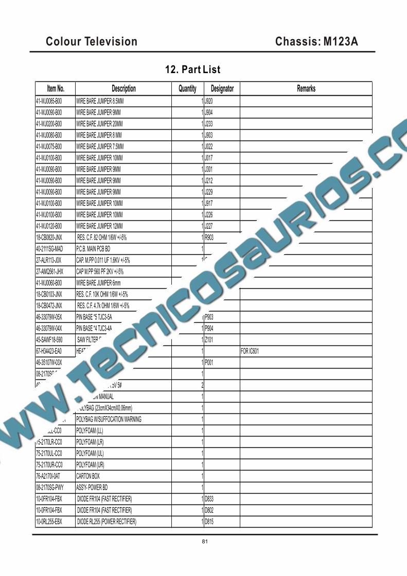
Item No. Description Quantity Designator Remarks
41-WJ0085-B00 WIRE BARE JUMPER 8.5MM 1 J920
41-WJ0090-B00 WIRE BARE JUMPER 9MM 1 J904
41-WJ0200-B00 WIRE BARE JUMPER 20MM 1 J233
41-WJ0080-B00 WIRE BARE JUMPER 8 MM 1 J903
41-WJ0075-B00 WIRE BARE JUMPER 7.5MM 1 J022
41-WJ0100-B00 WIRE BARE JUMPER 10MM 1 J017
41-WJ0090-B00 WIRE BARE JUMPER 9MM 1 J301
41-WJ0090-B00 WIRE BARE JUMPER 9MM 1 J212
41-WJ0090-B00 WIRE BARE JUMPER 9MM 1 J229
41-WJ0100-B00 WIRE BARE JUMPER 10MM 1 J917
41-WJ0100-B00 WIRE BARE JUMPER 10MM 1 J226
41-WJ0120-B00 WIRE BARE JUMPER 12MM 1 J227
18-CB0820-JNX RES. C.F. 82 OHM 1/6W +/-5% 1 R903
40-2111SG-MAD P.C.B. MAIN PCB BD 1
27-ALR113-J0X CAP. M.PP 0.011 UF 1.6KV +/-5% 1 C406B
27-AMQ561-JHX CAP M.PP 560 PF 2KV +/-5% 1 C402
41-WJ0060-B00 WIRE BARE JUMPER 6mm 1 R921
18-CB0103-JNX RES. C.F. 10K OHM 1/6W +/-5% 1 R052
18-CB0472-JNX RES. C.F. 4.7k OHM 1/6W +/-5% 1 R311
46-33079W-05X PIN BASE *5 TJC3-5A 1 P903
46-33079W-04X PIN BASE *4 TJC3-4A 1 P904
45-SAWF18-590 SAW FILTER F1859 1 Z101
67-H34423-EA0 HEAT SINK 1 FOR IC601
46-35107W-03X PIN BASE EH-3A 1 P001
08-2170SG-PAN ASS'Y- PACKING 1
49-382550-BAT BATTERY R06P AA 1.5V 5# 2
72-2170SG-E031A OPERATION MANUAL 1
74-022032-6WE POLYBAG (23cmX34cmX0.06mm) 1
74-120120-80HAA POLYBAG W/SUFFOCATION WARNING 1
75-2170LL-CC0 POLYFOAM (LL) 1
75-2170LR-CC0 POLYFOAM (LR) 1
75-2170UL-CC0 POLYFOAM (UL) 1
75-2170UR-CC0 POLYFOAM (UR) 1
76-A2170I-0AT CARTON BOX 1
08-2170SG-PWY ASS'Y- POWER BD 1
10-0FR104-FBX DIODE FR104 (FAST RECTIFIER) 1 D833
10-0FR104-FBX DIODE FR104 (FAST RECTIFIER) 1 D802
10-0RL255-EBX DIODE RL255 (POWER RECTIFIER) 1 D815
Colour Television Chassis: M123A
81
12. Part List
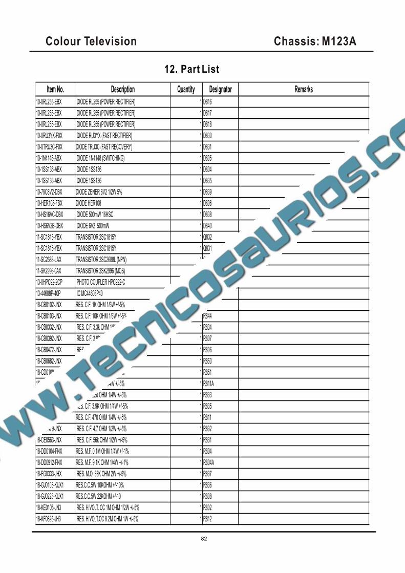
Item No. Description Quantity Designator Remarks
10-0RL255-EBX DIODE RL255 (POWER RECTIFIER) 1 D816
10-0RL255-EBX DIODE RL255 (POWER RECTIFIER) 1 D817
10-0RL255-EBX DIODE RL255 (POWER RECTIFIER) 1 D818
10-0RU3YX-F0X DIODE RU3YX (FAST RECTIFIER) 1 D830
10-0TRU3C-F0X DIODE TRU3C (FAST RECOVERY) 1 D831
10-1N4148-ABX DIODE 1N4148 (SWITCHING) 1 D805
10-1SS136-ABX DIODE 1SS136 1 D804
10-1SS136-ABX DIODE 1SS136 1 D835
10-79C8V2-DBX DIODE ZENER 8V2 1/2W 5% 1 D839
10-HER108-FBX DIODE HER108 1 D806
10-HS16VC-DBX DIODE 500mW 16HSC 1 D838
10-HS6V2B-DBX DIODE 6V2 500mW 1 D840
11-SC1815-YBX TRANSISTOR 2SC1815Y 1 Q832
11-SC1815-YBX TRANSISTOR 2SC1815Y 1 Q831
11-SC2688-LAX TRANSISTOR 2SC2688L (NPN) 1 Q830
11-SK2996-0AX TRANSISTOR 2SK2996 (MOS) 1 Q801
13-0HPC92-2CP PHOTO COUPLER HPC922-C 1 IC802
13-44608P-40P IC MC44608P40 1 IC801
18-CB0102-JNX RES. C.F. 1K OHM 1/6W +/-5% 1 R809
18-CB0103-JNX RES. C.F. 10K OHM 1/6W +/-5% 1 R844
18-CB0332-JNX RES. C.F. 3.3k OHM 1/6W +/-5% 1 R834
18-CB0392-JNX RES. C.F. 3.9K OHM 1/6W +/-5% 1 R807
18-CB0472-JNX RES. C.F. 4.7k OHM 1/6W +/-5% 1 R806
18-CB0682-JNX RES. C.F. 6.8K OHM 1/6W +/-5% 1 R850
18-CD0100-JNX RES. C.F. 10 OHM 1/4W +/-5% 1 R851
18-CD0220-JNX RES. C.F. 22 OHM 1/4W +/-5% 1 R811A
18-CD0221-JNX RES. C.F. 220 OHM 1/4W +/-5% 1 R833
18-CD0392-JNX RES. C.F. 3.9K OHM 1/4W +/-5% 1 R835
18-CD0471-JNX RES. C.F. 470 OHM 1/4W +/-5% 1 R811
18-CE0479-JNX RES. C.F. 4.7 OHM 1/2W +/-5% 1 R832
18-CE0563-JNX RES. C.F. 56k OHM 1/2W +/-5% 1 R831
18-DD0104-FNX RES. M.F. 0.1M OHM 1/4W +/-1% 1 R804
18-DD0912-FNX RES. M.F. 9.1K OHM 1/4W +/-1% 1 R804A
18-FG0333-JHX RES. M.O. 33K OHM 2W +/-5% 1 R837
18-GJ0103-KUX1 RES.C.C.5W 10KOHM +/-10% 1 R836
18-GJ0223-KUX1 RES.C.C.5W 22KOHM +/-10 1 R808
18-KE0105-JN3 RES. H.VOLT. CC 1M OHM 1/2W +/-5% 1 R802
18-KF0825-JH3 RES. H.VOLT.CC 8.2M OHM 1W +/-5% 1 R812
Colour Television Chassis: M123A
82
12. Part List
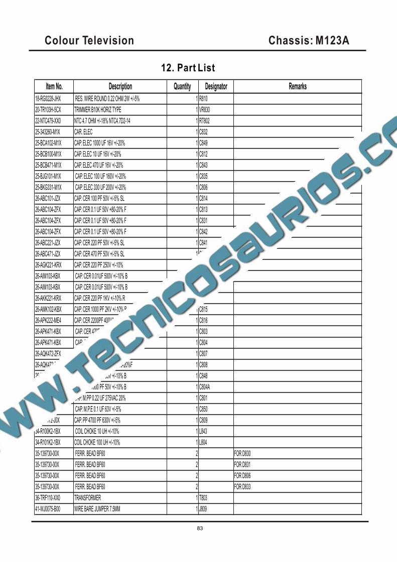
Item No. Description Quantity Designator Remarks
18-RG0228-JHX RES. WIRE ROUND 0.22 OHM 2W +/-5% 1 R810
20-TR103H-5CX TRIMMER B10K HORIZ TYPE 1 VR830
22-NTC479-XX0 NTC 4.7 OHM +/-18% NTC4.7D2-14 1 RT802
25-343260-M1X CAR. ELEC 1 C832
25-BCA102-M1X CAP. ELEC 1000 UF 16V +/-20% 1 C849
25-BCB100-M1X CAP. ELEC 10 UF 16V +/-20% 1 C812
25-BCB471-M1X CAP. ELEC 470 UF 16V +/-20% 1 C843
25-BJG101-M1X CAP. ELEC 100 UF 160V +/-20% 1 C835
25-BKG331-M1X CAP. ELEC 330 UF 200V +/-20% 1 C806
26-ABC101-JZX CAP. CER 100 PF 50V +/-5% SL 1 C814
26-ABC104-ZFX CAP. CER 0.1 UF 50V +80-20% F 1 C813
26-ABC104-ZFX CAP. CER 0.1 UF 50V +80-20% F 1 C831
26-ABC104-ZFX CAP. CER 0.1 UF 50V +80-20% F 1 C842
26-ABC221-JZX CAP. CER 220 PF 50V +/-5% SL 1 C841
26-ABC471-JZX CAP. CER 470 PF 50V +/-5% SL 1 C851
26-AGK221-KRX CAP. CER 220 PF 250V +/-10% 1 C830
26-AIM103-KBX CAP. CER 0.01UF 500V +/-10% B 1 C834
26-AIM103-KBX CAP. CER 0.01UF 500V +/-10% B 1 C805
26-AKK221-KRX CAP. CER 220 PF 1KV +/-10% R 1 C833
26-AMK102-KBX CAP. CER 1000 PF 2KV +/-10% B 1 C815
26-APK222-ME4 CAP. CER 2200PF 400VAC+/-20% E 1 C816
26-APK471-KBX CAP. CER 470PF 400VAC +/-10% B 1 C803
26-APK471-KBX CAP. CER 470PF 400VAC +/-10% B 1 C804
26-AQK472-ZFX CAP. CER 4700PF 250VAC+80-20%F 1 C807
26-AQK472-ZFX CAP. CER 4700PF 250VAC+80-20%F 1 C808
26-EBP102-KBX CAP. CER 1000 PF 50V +/-10% B 1 C848
26-EBP102-KBX CAP. CER 1000 PF 50V +/-10% B 1 C804A
27-AQT224-MVH CAP. M.PP 0.22 UF 275VAC 20% 1 C801
27-MBC104-J0X CAP. M.P.E 0.1 UF 63V +/-5% 1 C850
27-RJP472-J0X CAP. PP 4700 PF 630V +/-5% 1 C809
34-R100K2-1BX COIL CHOKE 10 UH +/-10% 1 L843
34-R101K2-1BX COIL CHOKE 100 UH +/-10% 1 L804
35-139730-00X FERR. BEAD BF60 2 FOR D830
35-139730-00X FERR. BEAD BF60 2 FOR D831
35-139730-00X FERR. BEAD BF60 2 FOR D806
35-139730-00X FERR. BEAD BF60 2 FOR D833
36-TRF110-XX0 TRANSFORMER 1 T803
41-WJ0075-B00 WIRE BARE JUMPER 7.5MM 1 J809
Colour Television Chassis: M123A
83
12. Part List
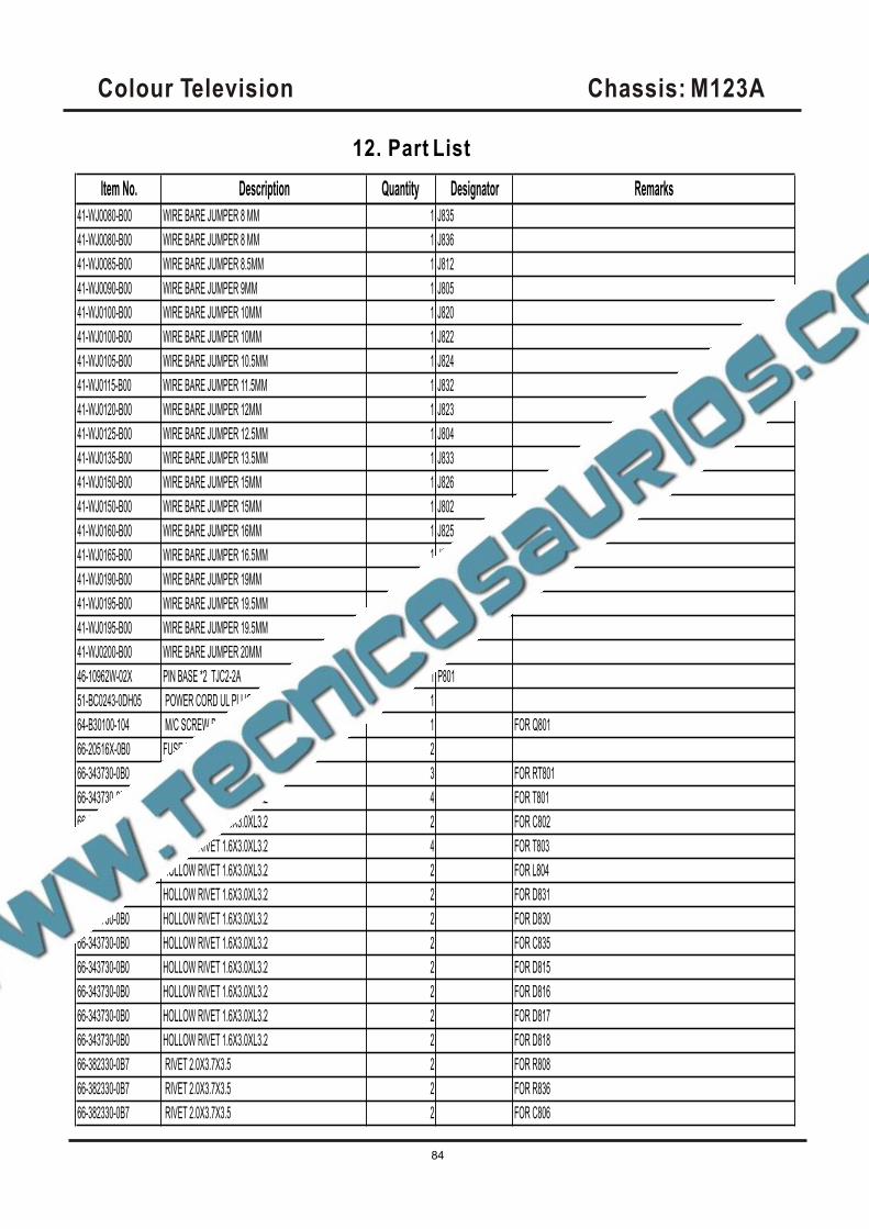
Item No. Description Quantity Designator Remarks
41-WJ0080-B00 WIRE BARE JUMPER 8 MM 1 J835
41-WJ0080-B00 WIRE BARE JUMPER 8 MM 1 J836
41-WJ0085-B00 WIRE BARE JUMPER 8.5MM 1 J812
41-WJ0090-B00 WIRE BARE JUMPER 9MM 1 J805
41-WJ0100-B00 WIRE BARE JUMPER 10MM 1 J820
41-WJ0100-B00 WIRE BARE JUMPER 10MM 1 J822
41-WJ0105-B00 WIRE BARE JUMPER 10.5MM 1 J824
41-WJ0115-B00 WIRE BARE JUMPER 11.5MM 1 J832
41-WJ0120-B00 WIRE BARE JUMPER 12MM 1 J823
41-WJ0125-B00 WIRE BARE JUMPER 12.5MM 1 J804
41-WJ0135-B00 WIRE BARE JUMPER 13.5MM 1 J833
41-WJ0150-B00 WIRE BARE JUMPER 15MM 1 J826
41-WJ0150-B00 WIRE BARE JUMPER 15MM 1 J802
41-WJ0160-B00 WIRE BARE JUMPER 16MM 1 J825
41-WJ0165-B00 WIRE BARE JUMPER 16.5MM 1 J831
41-WJ0190-B00 WIRE BARE JUMPER 19MM 1 J811
41-WJ0195-B00 WIRE BARE JUMPER 19.5MM 1 J828
41-WJ0195-B00 WIRE BARE JUMPER 19.5MM 1 J829
41-WJ0200-B00 WIRE BARE JUMPER 20MM 1 J830
46-10962W-02X PIN BASE *2 TJC2-2A 1 P801
51-BC0243-0DH05 POWER CORD UL PLUG W/HOUSING 1
64-B30100-104 M/C SCREW B 3 X 10 1 FOR Q801
66-20516X-0B0 FUSE HOLDER 2
66-343730-0B0 HOLLOW RIVET 1.6X3.0XL3.2 3 FOR RT801
66-343730-0B0 HOLLOW RIVET 1.6X3.0XL3.2 4 FOR T801
66-343730-0B0 HOLLOW RIVET 1.6X3.0XL3.2 2 FOR C802
66-343730-0B0 HOLLOW RIVET 1.6X3.0XL3.2 4 FOR T803
66-343730-0B0 HOLLOW RIVET 1.6X3.0XL3.2 2 FOR L804
66-343730-0B0 HOLLOW RIVET 1.6X3.0XL3.2 2 FOR D831
66-343730-0B0 HOLLOW RIVET 1.6X3.0XL3.2 2 FOR D830
66-343730-0B0 HOLLOW RIVET 1.6X3.0XL3.2 2 FOR C835
66-343730-0B0 HOLLOW RIVET 1.6X3.0XL3.2 2 FOR D815
66-343730-0B0 HOLLOW RIVET 1.6X3.0XL3.2 2 FOR D816
66-343730-0B0 HOLLOW RIVET 1.6X3.0XL3.2 2 FOR D817
66-343730-0B0 HOLLOW RIVET 1.6X3.0XL3.2 2 FOR D818
66-382330-0B7 RIVET 2.0X3.7X3.5 2 FOR R808
66-382330-0B7 RIVET 2.0X3.7X3.5 2 FOR R836
66-382330-0B7 RIVET 2.0X3.7X3.5 2 FOR C806
Colour Television Chassis: M123A
84
12. Part List
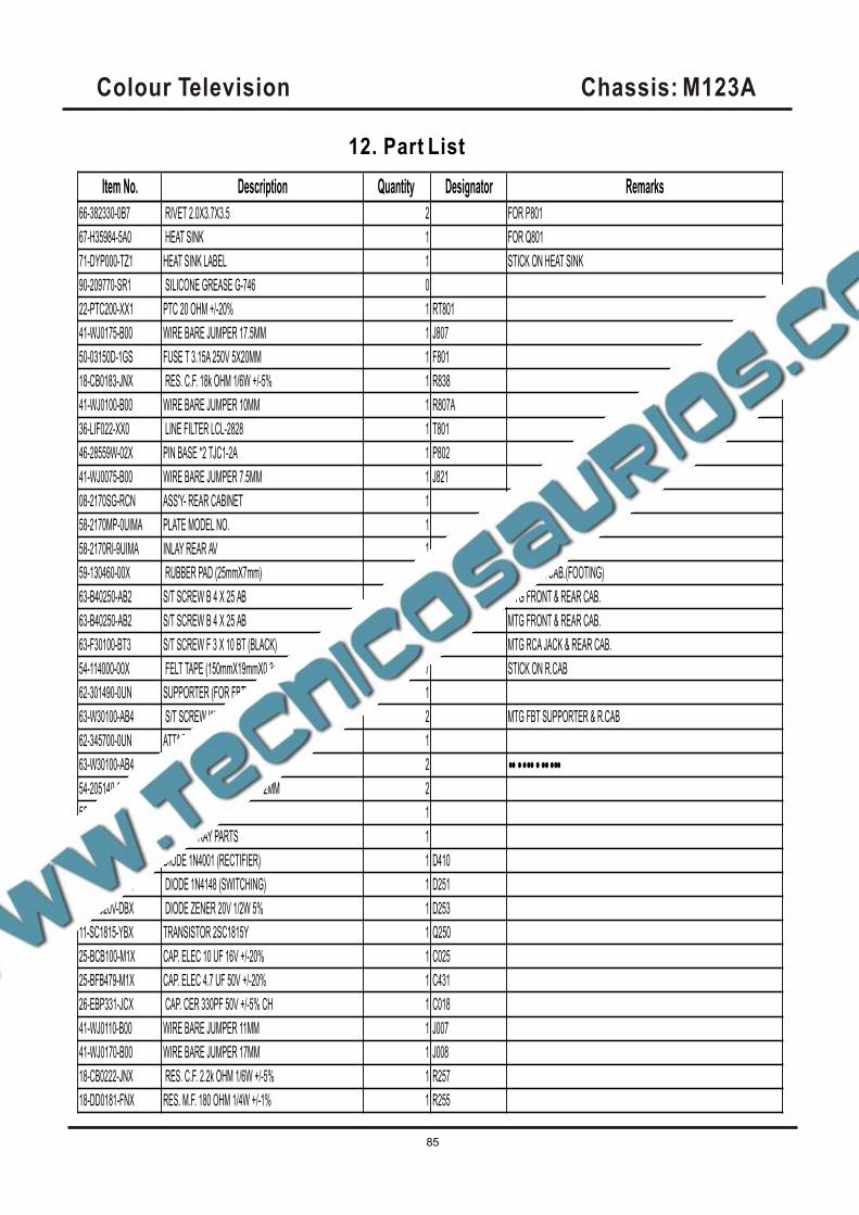
Item No. Description Quantity Designator Remarks
66-382330-0B7 RIVET 2.0X3.7X3.5 2 FOR P801
67-H35984-5A0 HEAT SINK 1 FOR Q801
71-DYP000-TZ1 HEAT SINK LABEL 1 STICK ON HEAT SINK
90-209770-SR1 SILICONE GREASE G-746 0
22-PTC200-XX1 PTC 20 OHM +/-20% 1 RT801
41-WJ0175-B00 WIRE BARE JUMPER 17.5MM 1 J807
50-03150D-1GS FUSE T 3.15A 250V 5X20MM 1 F801
18-CB0183-JNX RES. C.F. 18k OHM 1/6W +/-5% 1 R838
41-WJ0100-B00 WIRE BARE JUMPER 10MM 1 R807A
36-LIF022-XX0 LINE FILTER LCL-2828 1 T801
46-28559W-02X PIN BASE *2 TJC1-2A 1 P802
41-WJ0075-B00 WIRE BARE JUMPER 7.5MM 1 J821
08-2170SG-RCN ASS'Y- REAR CABINET 1
58-2170MP-0UIMA PLATE MODEL NO. 1
58-2170RI-9UIMA INLAY REAR AV 1
59-130460-00X RUBBER PAD (25mmX7mm) 2 FOR REAR CAB.(FOOTING)
63-B40250-AB2 S/T SCREW B 4 X 25 AB 2 MTG FRONT & REAR CAB.
63-B40250-AB2 S/T SCREW B 4 X 25 AB 4 MTG FRONT & REAR CAB.
63-F30100-BT3 S/T SCREW F 3 X 10 BT (BLACK) 2 MTG RCA JACK & REAR CAB.
54-114000-00X FELT TAPE (150mmX19mmX0.3mm) 7 STICK ON R.CAB
62-301490-0UN SUPPORTER (FOR FBT) 1
63-W30100-AB4 S/T SCREW W 3 X 10 AB 2 MTG FBT SUPPORTER & R.CAB
62-345700-0UN ATTACHMENT RAIL PIPS-KINGFA 113 (VO) 1
63-W30100-AB4 S/T SCREW W 3 X 10 AB 2 ••••••••••••
54-205140-000 SPACER CRT MOUNTING T=2MM 2
55-2170RC-1UN5F REAR CABINET 1
08-2170SG-XRY ASS'Y- X- RAY PARTS 1
10-1N4001-EBX DIODE 1N4001 (RECTIFIER) 1 D410
10-1N4148-ABX DIODE 1N4148 (SWITCHING) 1 D251
10-79C20V-DBX DIODE ZENER 20V 1/2W 5% 1 D253
11-SC1815-YBX TRANSISTOR 2SC1815Y 1 Q250
25-BCB100-M1X CAP. ELEC 10 UF 16V +/-20% 1 C025
25-BFB479-M1X CAP. ELEC 4.7 UF 50V +/-20% 1 C431
26-EBP331-JCX CAP. CER 330PF 50V +/-5% CH 1 C018
41-WJ0110-B00 WIRE BARE JUMPER 11MM 1 J007
41-WJ0170-B00 WIRE BARE JUMPER 17MM 1 J008
18-CB0222-JNX RES. C.F. 2.2k OHM 1/6W +/-5% 1 R257
18-DD0181-FNX RES. M.F. 180 OHM 1/4W +/-1% 1 R255
Colour Television Chassis: M123A
85
12. Part List
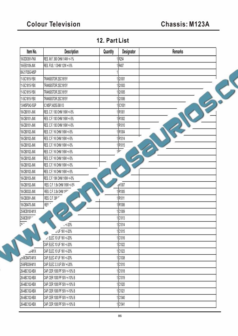
Item No. Description Quantity Designator Remarks
18-DD0391-FNX RES. M.F. 390 OHM 1/4W +/-1% 1 R254
18-EE0109-JNX RES. FUS. 1 OHM 1/2W +/-5% 1 R407
08-2170SG-MSP 1
11-SC1815-YBX TRANSISTOR 2SC1815Y 1 Q1001
11-SC1815-YBX TRANSISTOR 2SC1815Y 1 Q1003
11-SC1815-YBX TRANSISTOR 2SC1815Y 1 Q1005
11-SC1815-YBX TRANSISTOR 2SC1815Y 1 Q1006
13-MSP342-5GP IC MSP 3425G B8 V3 1 IC1001
18-CB0101-JNX RES. C.F. 100 OHM 1/6W +/-5% 1 R1001
18-CB0101-JNX RES. C.F. 100 OHM 1/6W +/-5% 1 R1002
18-CB0101-JNX RES. C.F. 100 OHM 1/6W +/-5% 1 R1010
18-CB0102-JNX RES. C.F. 1K OHM 1/6W +/-5% 1 R1004
18-CB0102-JNX RES. C.F. 1K OHM 1/6W +/-5% 1 R1014
18-CB0102-JNX RES. C.F. 1K OHM 1/6W +/-5% 1 R1015
18-CB0102-JNX RES. C.F. 1K OHM 1/6W +/-5% 1 R1016
18-CB0102-JNX RES. C.F. 1K OHM 1/6W +/-5% 1 R1017
18-CB0102-JNX RES. C.F. 1K OHM 1/6W +/-5% 1 R1022
18-CB0102-JNX RES. C.F. 1K OHM 1/6W +/-5% 1 R1023
18-CB0103-JNX RES. C.F. 10K OHM 1/6W +/-5% 1 R1003
18-CB0152-JNX RES. C.F. 1.5k OHM 1/6W +/-5% 1 R1007
18-CB0332-JNX RES. C.F. 3.3k OHM 1/6W +/-5% 1 R1005
18-CB0391-JNX RES. C.F. 390 OHM 1/6W +/-5% 1 R1011
18-CB0470-JNX RES. C.F. 47 OHM 1/6W +/-5% 1 R1006
25-BCB100-M1X CAP. ELEC 10 UF 16V +/-20% 1 C1009
25-BCB100-M1X CAP. ELEC 10 UF 16V +/-20% 1 C1013
25-BCB100-M1X CAP. ELEC 10 UF 16V +/-20% 1 C1014
25-BCB100-M1X CAP. ELEC 10 UF 16V +/-20% 1 C1015
25-BCB100-M1X CAP. ELEC 10 UF 16V +/-20% 1 C1016
25-BCB100-M1X CAP. ELEC 10 UF 16V +/-20% 1 C1022
25-BCB100-M1X CAP. ELEC 10 UF 16V +/-20% 1 C1023
25-BCB470-M1X CAP. ELEC 47 UF 16V +/-20% 1 C1038
25-BFB339-M1X CAP. ELEC 3.3 UF 50V +/-20% 1 C1010
26-ABC102-KBX CAP. CER 1000 PF 50V +/-10% B 1 C1018
26-ABC102-KBX CAP. CER 1000 PF 50V +/-10% B 1 C1019
26-ABC102-KBX CAP. CER 1000 PF 50V +/-10% B 1 C1020
26-ABC102-KBX CAP. CER 1000 PF 50V +/-10% B 1 C1021
26-ABC102-KBX CAP. CER 1000 PF 50V +/-10% B 1 C1040
26-ABC102-KBX CAP. CER 1000 PF 50V +/-10% B 1 C1041
Colour Television Chassis: M123A
86
12. Part List
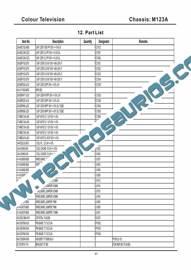
Item No. Description Quantity Designator Remarks
26-ABC152-KBX CAP. CER 1500 PF 50V +/-10% B 1 C1012
26-ABC339-CZX CAP. CER 3.3 PF 50V +/-0.25 SL 1 C1001
26-ABC339-CZX CAP. CER 3.3 PF 50V +/-0.25 SL 1 C1002
26-EBP103-ZFX CAP. CER 0.01UF 50V +80/-20% F 1 C1031
26-EBP103-ZFX CAP. CER 0.01UF 50V +80/-20% F 1 C1032
26-EBP103-ZFX CAP. CER 0.01UF 50V +80/-20% F 1 C1033
26-EBP103-ZFX CAP. CER 0.01UF 50V +80/-20% F 1 C1034
26-EBP220-JCX CAP. CER 22PF 50V +/-5% CH 1 C1035
40-2111SG-MPC MPS BD 1
26-EBP471-JCX CAP. CER 470PF 50V +/-5% CH 1 C1025
26-EBP220-JCX CAP. CER 22PF 50V +/-5% CH 1 C1036
26-EBP560-JZX CAP. CER 56PF 50V +/-5% SL TUBE 1 C1004
26-EBP560-JZX CAP. CER 56PF 50V +/-5% SL TUBE 1 C1005
27-MBC104-J0X CAP. M.P.E 0.1 UF 63V +/-5% 1 C1006
27-MBC104-J0X CAP. M.P.E 0.1 UF 63V +/-5% 1 C1008
27-MBC104-J0X CAP. M.P.E 0.1 UF 63V +/-5% 1 C1011
27-MBC104-J0X CAP. M.P.E 0.1 UF 63V +/-5% 1 C1037
27-MBC474-J0X CAP. M.P.E 0.47UF 63V +/-5% 1 C1039
34-R220J2-0EX COIL PL - 22 UH +/-5% 1 L1001
34-A100K0-0IX COIL CHOKE 10 UH +/-10% 1 J1002
34-A100K0-0IX COIL CHOKE 10 UH +/-10% 1 J1004
41-WJ0065-B00 WIRE BARE JUMPER 6.5MM 1 J1007
41-WJ0065-B00 WIRE BARE JUMPER 6.5MM 1 J1003
41-WJ0065-B00 WIRE BARE JUMPER 6.5MM 1 J1008
41-WJ0065-B00 WIRE BARE JUMPER 6.5MM 1 J1009
41-WJ0065-B00 WIRE BARE JUMPER 6.5MM 1 J1013
41-WJ0065-B00 WIRE BARE JUMPER 6.5MM 1 J1014
41-WJ0065-B00 WIRE BARE JUMPER 6.5MM 1 J1015
41-WJ0065-B00 WIRE BARE JUMPER 6.5MM 1 J1016
41-WJ0070-B00 WIRE BARE JUMPER 7MM 1 J1005
41-WJ0070-B00 WIRE BARE JUMPER 7MM 1 J1006
41-WJ0075-B00 WIRE BARE JUMPER 7.5MM 1 J1001
45-OSC18M-4Y0 CRYSTAL 18.432M 1 X1001
46-33079W-03X PIN BASE *3 TJC3-3A 1 P1002
46-33079W-03X PIN BASE *3 TJC3-3A 1 P1003
46-33079W-03X PIN BASE *3 TJC3-3A 1 P1004
46-21550W-09X HEADER *9 TS9B-SQ-1 1 P1001(2-10)
67-257870-1T0 BRACKET IF BD 1 FOR MSP BD TO M.BD
Colour Television Chassis: M123A
87
12. Part List
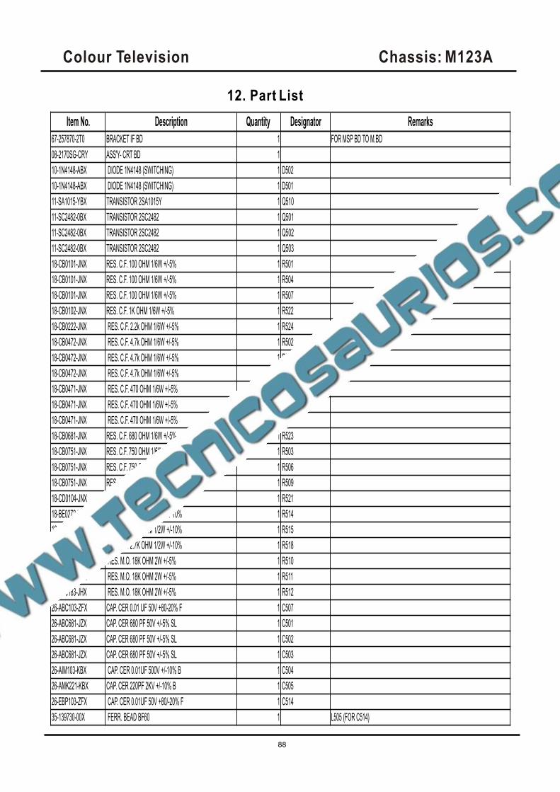
Item No. Description Quantity Designator Remarks
67-257870-2T0 BRACKET IF BD 1 FOR MSP BD TO M.BD
08-2170SG-CRY ASS'Y- CRT BD 1
10-1N4148-ABX DIODE 1N4148 (SWITCHING) 1 D502
10-1N4148-ABX DIODE 1N4148 (SWITCHING) 1 D501
11-SA1015-YBX TRANSISTOR 2SA1015Y 1 Q510
11-SC2482-0BX TRANSISTOR 2SC2482 1 Q501
11-SC2482-0BX TRANSISTOR 2SC2482 1 Q502
11-SC2482-0BX TRANSISTOR 2SC2482 1 Q503
18-CB0101-JNX RES. C.F. 100 OHM 1/6W +/-5% 1 R501
18-CB0101-JNX RES. C.F. 100 OHM 1/6W +/-5% 1 R504
18-CB0101-JNX RES. C.F. 100 OHM 1/6W +/-5% 1 R507
18-CB0102-JNX RES. C.F. 1K OHM 1/6W +/-5% 1 R522
18-CB0222-JNX RES. C.F. 2.2k OHM 1/6W +/-5% 1 R524
18-CB0472-JNX RES. C.F. 4.7k OHM 1/6W +/-5% 1 R502
18-CB0472-JNX RES. C.F. 4.7k OHM 1/6W +/-5% 1 R505
18-CB0472-JNX RES. C.F. 4.7k OHM 1/6W +/-5% 1 R508
18-CB0471-JNX RES. C.F. 470 OHM 1/6W +/-5% 1 R525
18-CB0471-JNX RES. C.F. 470 OHM 1/6W +/-5% 1 R526
18-CB0471-JNX RES. C.F. 470 OHM 1/6W +/-5% 1 R527
18-CB0681-JNX RES. C.F. 680 OHM 1/6W +/-5% 1 R523
18-CB0751-JNX RES. C.F. 750 OHM 1/6W +/-5% 1 R503
18-CB0751-JNX RES. C.F. 750 OHM 1/6W +/-5% 1 R506
18-CB0751-JNX RES. C.F. 750 OHM 1/6W +/-5% 1 R509
18-CD0104-JNX RES. C.F. 100K OHM 1/4W +/-5% 1 R521
18-BE0272-KFX RES. C.C. 2.7K OHM 1/2W +/-10% 1 R514
18-BE0272-KFX RES. C.C. 2.7K OHM 1/2W +/-10% 1 R515
18-BE0272-KFX RES. C.C. 2.7K OHM 1/2W +/-10% 1 R518
18-FG0183-JHX RES. M.O. 18K OHM 2W +/-5% 1 R510
18-FG0183-JHX RES. M.O. 18K OHM 2W +/-5% 1 R511
18-FG0183-JHX RES. M.O. 18K OHM 2W +/-5% 1 R512
26-ABC103-ZFX CAP. CER 0.01 UF 50V +80-20% F 1 C507
26-ABC681-JZX CAP. CER 680 PF 50V +/-5% SL 1 C501
26-ABC681-JZX CAP. CER 680 PF 50V +/-5% SL 1 C502
26-ABC681-JZX CAP. CER 680 PF 50V +/-5% SL 1 C503
26-AIM103-KBX CAP. CER 0.01UF 500V +/-10% B 1 C504
26-AMK221-KBX CAP. CER 220PF 2KV +/-10% B 1 C505
26-EBP103-ZFX CAP. CER 0.01UF 50V +80/-20% F 1 C514
35-139730-00X FERR. BEAD BF60 1 L505 (FOR C514)
Colour Television Chassis: M123A
88
12. Part List
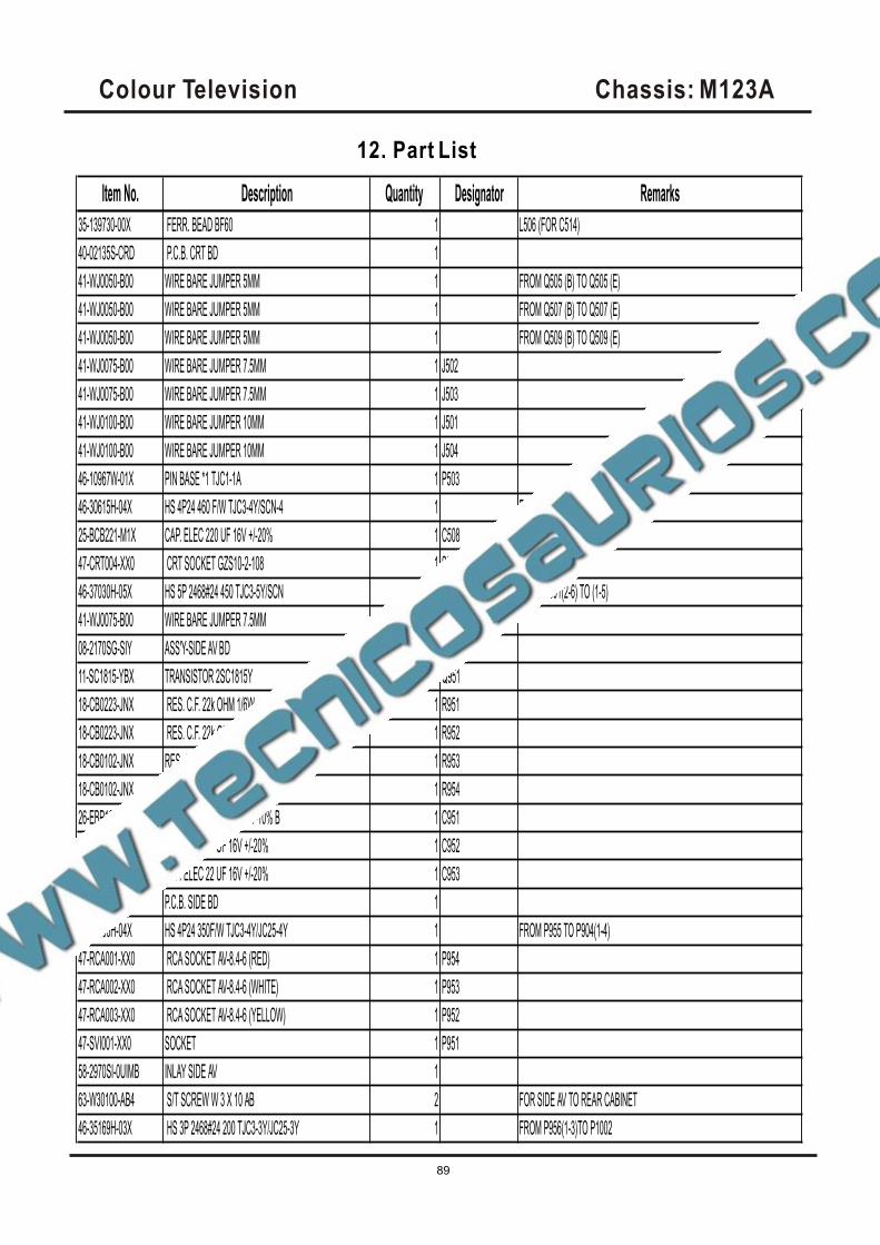
Item No. Description Quantity Designator Remarks
35-139730-00X FERR. BEAD BF60 1 L506 (FOR C514)
40-02135S-CRD P.C.B. CRT BD 1
41-WJ0050-B00 WIRE BARE JUMPER 5MM 1 FROM Q505 (B) TO Q505 (E)
41-WJ0050-B00 WIRE BARE JUMPER 5MM 1 FROM Q507 (B) TO Q507 (E)
41-WJ0050-B00 WIRE BARE JUMPER 5MM 1 FROM Q509 (B) TO Q509 (E)
41-WJ0075-B00 WIRE BARE JUMPER 7.5MM 1 J502
41-WJ0075-B00 WIRE BARE JUMPER 7.5MM 1 J503
41-WJ0100-B00 WIRE BARE JUMPER 10MM 1 J501
41-WJ0100-B00 WIRE BARE JUMPER 10MM 1 J504
46-10967W-01X PIN BASE *1 TJC1-1A 1 P503
46-30615H-04X HS 4P24 460 F/W TJC3-4Y/SCN-4 1 FROM P502 TO M.BD P402
25-BCB221-M1X CAP. ELEC 220 UF 16V +/-20% 1 C508
47-CRT004-XX0 CRT SOCKET GZS10-2-108 1 S501
46-37030H-05X HS 5P 2468#24 450 TJC3-5Y/SCN 1 FROM P501(2-6) TO (1-5)
41-WJ0075-B00 WIRE BARE JUMPER 7.5MM 1 J505
08-2170SG-SIY ASS'Y-SIDE AV BD 1
11-SC1815-YBX TRANSISTOR 2SC1815Y 1 Q951
18-CB0223-JNX RES. C.F. 22k OHM 1/6W +/-5% 1 R951
18-CB0223-JNX RES. C.F. 22k OHM 1/6W +/-5% 1 R952
18-CB0102-JNX RES. C.F. 1K OHM 1/6W +/-5% 1 R953
18-CB0102-JNX RES. C.F. 1K OHM 1/6W +/-5% 1 R954
26-EBP102-KBX CAP. CER 1000 PF 50V +/-10% B 1 C951
25-BCB220-M1X CAP. ELEC 22 UF 16V +/-20% 1 C952
25-BCB220-M1X CAP. ELEC 22 UF 16V +/-20% 1 C953
40-2170SG-SIB P.C.B. SIDE BD 1
46-27266H-04X HS 4P24 350F/W TJC3-4Y/JC25-4Y 1 FROM P955 TO P904(1-4)
47-RCA001-XX0 RCA SOCKET AV-8.4-6 (RED) 1 P954
47-RCA002-XX0 RCA SOCKET AV-8.4-6 (WHITE) 1 P953
47-RCA003-XX0 RCA SOCKET AV-8.4-6 (YELLOW) 1 P952
47-SVI001-XX0 SOCKET 1 P951
58-2970SI-0UIMB INLAY SIDE AV 1
63-W30100-AB4 S/T SCREW W 3 X 10 AB 2 FOR SIDE AV TO REAR CABINET
46-35169H-03X HS 3P 2468#24 200 TJC3-3Y/JC25-3Y 1 FROM P956(1-3)TO P1002
Colour Television Chassis: M123A
89
12. Part List