Embed Size (px)
Citation preview
Electrical Machines Lab Forth Year M2: Fractional HP Motors
Faculty of Engineering Cairo University Electrical Power and Machines Dept.
1
M2 Fractional HP Motors Performance of Reluctance, Universal and Stepper Motors
Introduction In this lab session the following motors will be studied and tested:
1. Synchronous Reluctance Motor. 2. Universal Motor. 3. Stepper Motor.
I. Synchronous Reluctance Motor (S.R.M): Background Synchronous machines are mainly divided into two groups, cylindrical and salient pole machines. The first one has a uniform air gap. The second one, and due to the saliency, has different air gap lengths in direct and quadrature axes. The resultant torque in this case contains two components, one depends on excitation, and the other dose not and is due to the axis reluctance variation.
T T TS R= +
)2sin(2
)(3)sin(32
δω
δω qds
qd
ds
oc
xxxxV
xVET −
+=
Where, Ts represents the torque due to excitation voltage Eoc (the same as for cylindrical machine), TR represents the effect of salient poles and called the reluctance torque. A synchronous reluctance motor, that doesn't have any dc excitation, produces only reluctance torque. Note that in a synch motor, cage windings may be used to start as an induction motor. Electrodynamometer: It is a special machine used as a mechanical load torque. It consists of a cage rotor and salient pole stator excited from a rectifier circuit that is supplied from variac. Its principle depends on the torque produced on the rotor when rotates in the static field. This torque represents the load torque. Measuring of toque is satisfied through an angular spring attached to the free rotating stator. As the torque on the rotor is equal and opposite to the torque produced on the stator, the rotation angle of the stator is proportional to the torque.
Electrical Machines Lab Forth Year M2: Fractional HP Motors
Faculty of Engineering Cairo University Electrical Power and Machines Dept.
2
Test1: Pull Out Torque Procedure:
1. Connect the circuit as shown in Fig1. 2. Make sure that the initial torque is zero and rated voltage is applied. 3. At various load torques, reduce the voltage gradually till the motor pulls out.
Disconnect the supply and measure the voltage. 4. Draw the pull-out-torque voltage relation and get the value of torque at rated voltage
using extrapolation. Test 2: Motor Performance Procedure:
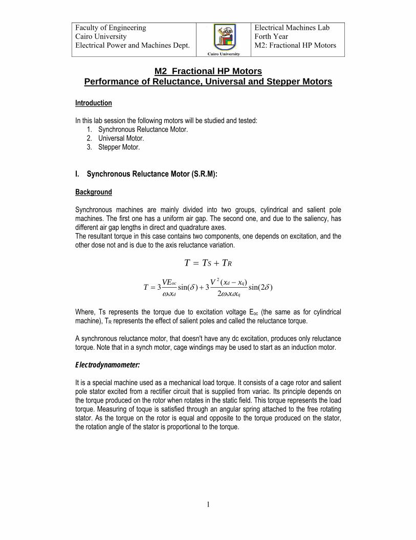
1. Connect the circuit as shown in Fig1. 2. Apply the rated voltage on the motor. 3. At various load torques, get the current and watt meters readings. 4. Draw the relation of efficiency, power factor and current against the load torque.
Fig. 1: SRM circuit diagram. Test 3: Sub-transient impedances Procedure:
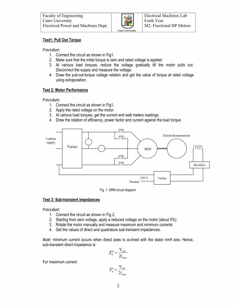
1. Connect the circuit as shown in Fig 2. 2. Starting from zero voltage, apply a reduced voltage on the motor (about 5%). 3. Rotate the motor manually and measure maximum and minimum currents. 4. Get the values of direct and quadrature sub-transient impedances.
Note: minimum current occurs when direct axes is co-lined with the stator mmf axis. Hence, sub-transient direct impedance is:
′′ =Z Vidred
2 min For maximum current:
′′ =Z Viqred
2 max
220 V Neutral
Electrodynamometer
SRM
3-phase supply
Variac
Variac
Rectifier
Electrical Machines Lab Forth Year M2: Fractional HP Motors
Faculty of Engineering Cairo University Electrical Power and Machines Dept.
3
Fig 2
II. Universal Motor: Background Serial single-phase series-motors (universal motors) can be used with either dc source or a single-phase ac source. They are widely used in fractional Hp ratings in many domestic applications such as portable tools, drills, mixers and vacuum cleaners and usually are light in weight and of high speed rating. Procedure:
1. Connect the motor to an ac supply and then to a dc supply of the rated voltage. 2. Measure current and speed in both cases. 3. Measure the input power for ac case. 4. Calculate the supply power factor. 5. Compare the readings of both cases.
III. Stepper Motor: Background
A stepper motor rotates by a specific angle in response to an input electrical pulse. The stepper motor in an electromagnetic incremental actuator that can convert digital pulse inputs into analog output shaft motions. It is therefore, used in digital control systems. A train of pulses is made to turn the shaft of the motor by steps called step angles. Typical applications of stepper motors are printers, tape drives, disk drives, machine tools, process control systems and robots.
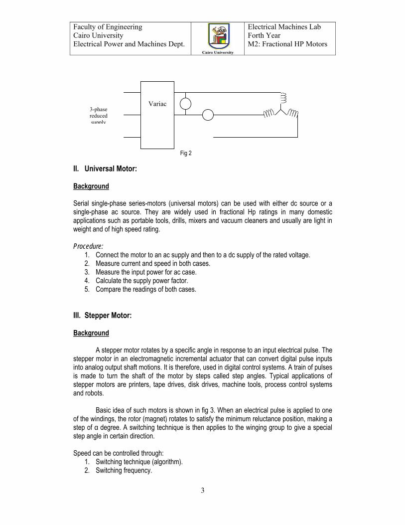
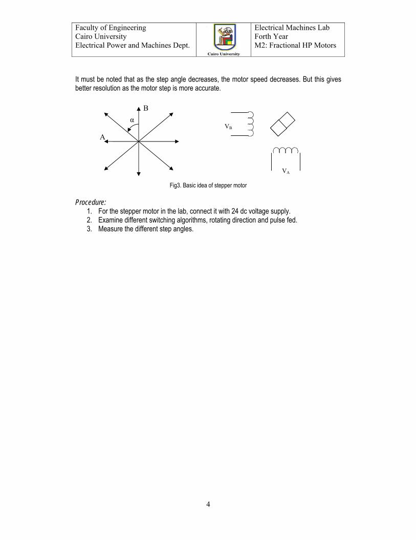
Basic idea of such motors is shown in fig 3. When an electrical pulse is applied to one of the windings, the rotor (magnet) rotates to satisfy the minimum reluctance position, making a step of α degree. A switching technique is then applies to the winging group to give a special step angle in certain direction. Speed can be controlled through:
1. Switching technique (algorithm). 2. Switching frequency.
Variac 3-phase reduced supply
Electrical Machines Lab Forth Year M2: Fractional HP Motors
Faculty of Engineering Cairo University Electrical Power and Machines Dept.
4
It must be noted that as the step angle decreases, the motor speed decreases. But this gives better resolution as the motor step is more accurate.
Fig3. Basic idea of stepper motor
Procedure:
1. For the stepper motor in the lab, connect it with 24 dc voltage supply. 2. Examine different switching algorithms, rotating direction and pulse fed. 3. Measure the different step angles.
B
A
VB
α
VA
Electrical Machines Lab Forth Year M2: Fractional HP Motors
Faculty of Engineering Cairo University Electrical Power and Machines Dept.
5
M2: Fractional HP Motors Lab Results
I. Synchronous Reluctance Motor
Test (1): Pullout Torque V (Volt) Tpo (N.m) Test (2): Motor Performance
T (N.m) I (A)
Pin (Watt) Pout (Watt)
P.F (η)
Test (3): Sub-transient impedances
=
=
max
min
I
I
II. Universal Motor a) DC Supply Case
==
dc
dc
nI
b) AC Supply Case
==
ac
ac
nI

Electrical Machines Lab Forth Year M2: Fractional HP Motors
Faculty of Engineering Cairo University Electrical Power and Machines Dept.
6
M2: Fractional HP Motors Curves and Characteristics
Electrical Machines Lab Forth Year M2: Fractional HP Motors
Faculty of Engineering Cairo University Electrical Power and Machines Dept.
7
Appendix of M2 (Fractional HP Motors)
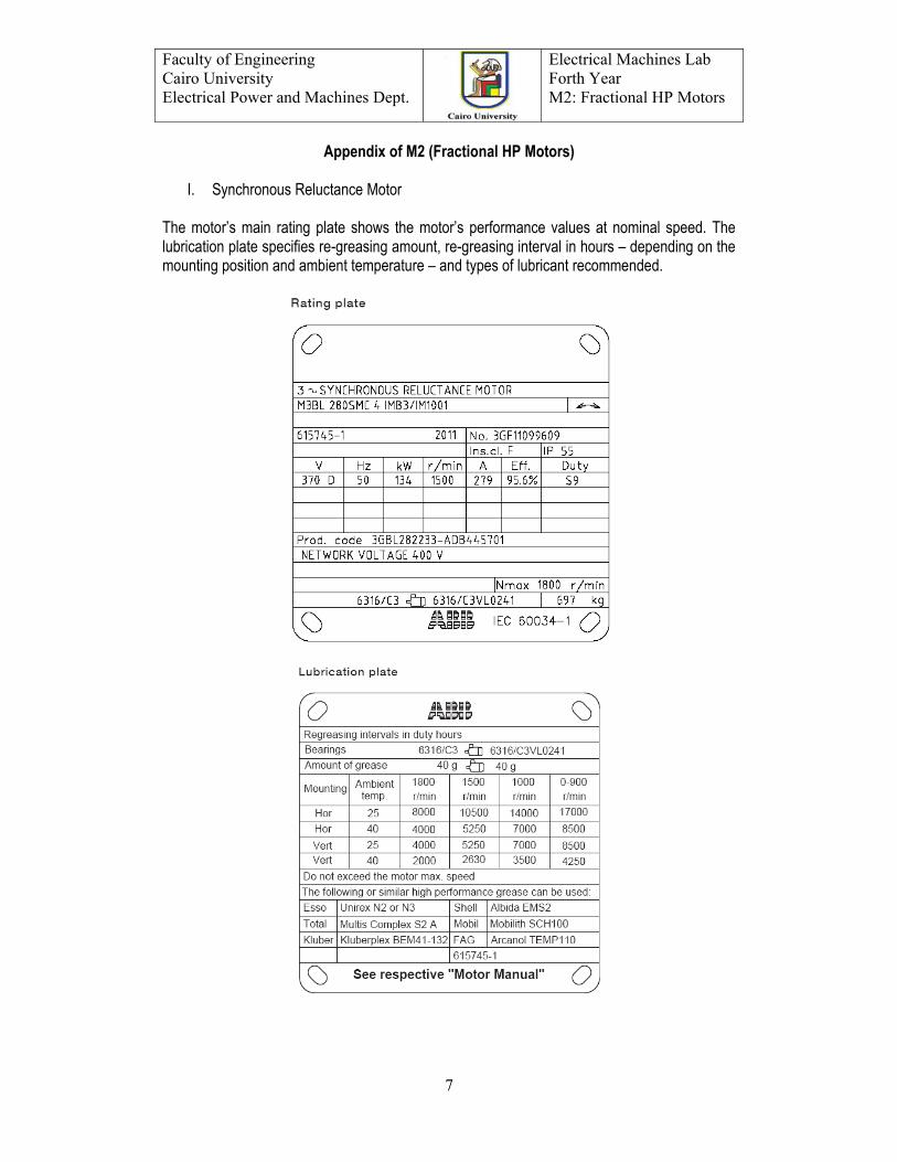
I. Synchronous Reluctance Motor The motor’s main rating plate shows the motor’s performance values at nominal speed. The lubrication plate specifies re-greasing amount, re-greasing interval in hours – depending on the mounting position and ambient temperature – and types of lubricant recommended.
Electrical Machines Lab Forth Year M2: Fractional HP Motors
Faculty of Engineering Cairo University Electrical Power and Machines Dept.
8
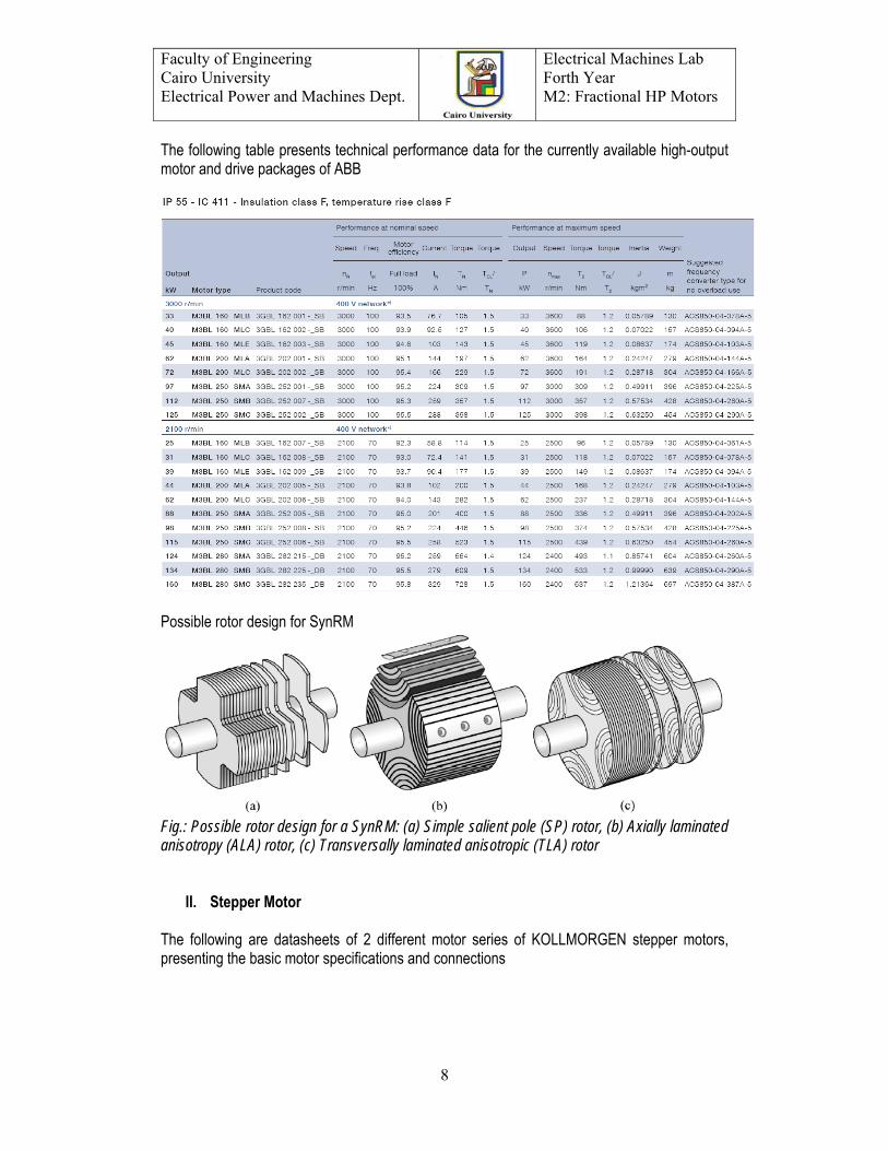
The following table presents technical performance data for the currently available high-output motor and drive packages of ABB
Possible rotor design for SynRM
Fig.: Possible rotor design for a SynRM: (a) Simple salient pole (SP) rotor, (b) Axially laminated anisotropy (ALA) rotor, (c) Transversally laminated anisotropic (TLA) rotor
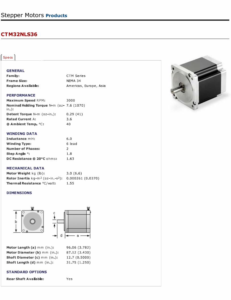
II. Stepper Motor The following are datasheets of 2 different motor series of KOLLMORGEN stepper motors, presenting the basic motor specifications and connections
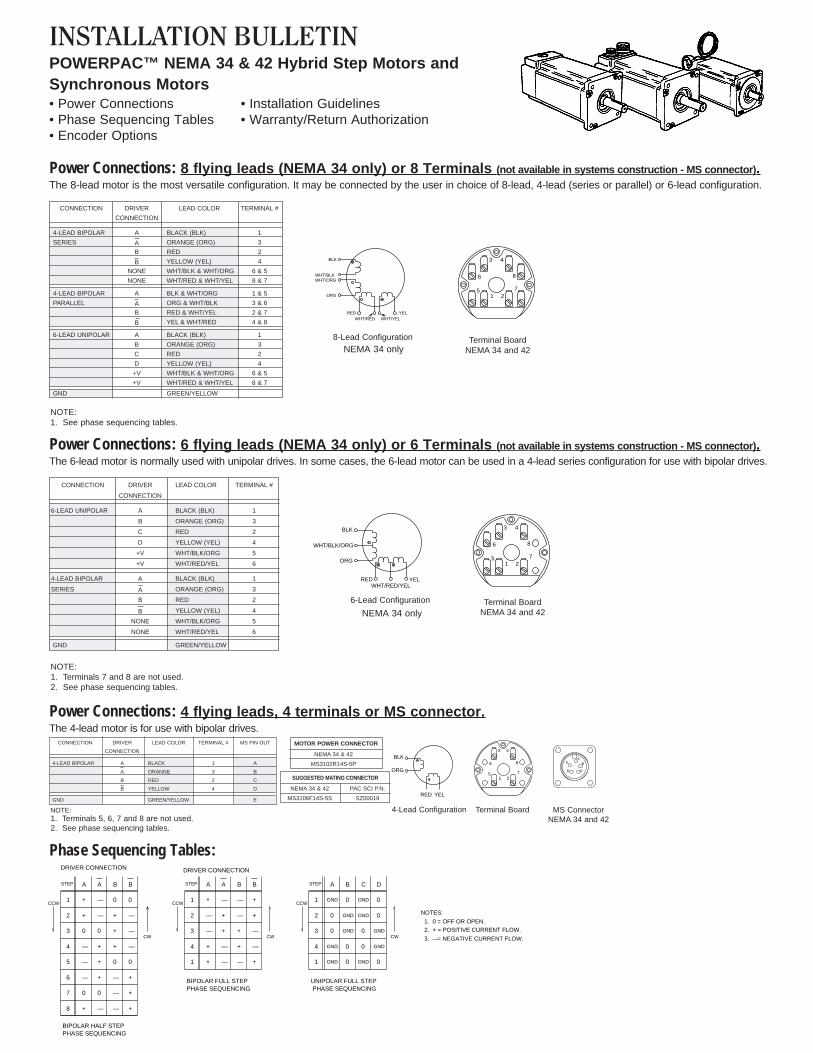
INSTALLATION BULLETINPOWERPAC™ NEMA 34 & 42 Hybrid Step Motors andSynchronous Motors• Power Connections • Installation Guidelines• Phase Sequencing Tables • Warranty/Return Authorization• Encoder Options
Power Connections: 8 flying leads (NEMA 34 only) or 8 Terminals (not available in systems construction - MS connector).The 8-lead motor is the most versatile configuration. It may be connected by the user in choice of 8-lead, 4-lead (series or parallel) or 6-lead configuration.
Power Connections: 6 flying leads (NEMA 34 only) or 6 Terminals (not available in systems construction - MS connector).The 6-lead motor is normally used with unipolar drives. In some cases, the 6-lead motor can be used in a 4-lead series configuration for use with bipolar drives.
Power Connections: 4 flying leads, 4 terminals or MS connector.The 4-lead motor is for use with bipolar drives.
NOTE:1. See phase sequencing tables.
CONNECTION DRIVER LEAD COLOR TERMINAL #
CONNECTION
4-LEAD BIPOLAR A BLACK (BLK) 1
SERIES A ORANGE (ORG) 3
B RED 2
B YELLOW (YEL) 4
NONE WHT/BLK & WHT/ORG 6 & 5
NONE WHT/RED & WHT/YEL 8 & 7
4-LEAD BIPOLAR A BLK & WHT/ORG 1 & 5
PARALLEL A ORG & WHT/BLK 3 & 6
B RED & WHT/YEL 2 & 7
B YEL & WHT/RED 4 & 8
6-LEAD UNIPOLAR A BLACK (BLK) 1
B ORANGE (ORG) 3
C RED 2
D YELLOW (YEL) 4
+V WHT/BLK & WHT/ORG 6 & 5
+V WHT/RED & WHT/YEL 8 & 7
GND GREEN/YELLOW
YELWHT/YELWHT/RED
RED
ORG
WHT/ORGWHT/BLK
BLK
8-Lead Configuration
6
3 4
8
721
5
Terminal BoardNEMA 34 and 42
YELWHT/RED/YEL
RED
ORG
WHT/BLK/ORG
BLK
6-Lead Configuration Terminal BoardNEMA 34 and 42
CONNECTION DRIVER LEAD COLOR TERMINAL #
CONNECTION
6-LEAD UNIPOLAR A BLACK (BLK) 1
B ORANGE (ORG) 3
C RED 2
D YELLOW (YEL) 4
+V WHT/BLK/ORG 5
+V WHT/RED/YEL 6
4-LEAD BIPOLAR A BLACK (BLK) 1
SERIES A ORANGE (ORG) 3
B RED 2
B YELLOW (YEL) 4
NONE WHT/BLK/ORG 5
NONE WHT/RED/YEL 6
GND GREEN/YELLOW
NOTE:1. Terminals 7 and 8 are not used.2. See phase sequencing tables.
6
3 4
8
721
5
MOTOR POWER CONNECTOR
NEMA 34 & 42
MS3102R14S-5P
CONNECTION DRIVER LEAD COLOR TERMINAL # MS PIN OUT
CONNECTION
4-LEAD BIPOLAR A BLACK 1 A
A ORANGE 3 B
B RED 2 C
B YELLOW 4 D
GND GREEN/YELLOW E
NOTE:1. Terminals 5, 6, 7 and 8 are not used.2. See phase sequencing tables.
Terminal Board4-Lead Configuration
YELRED
ORG
BLK
SUGGESTED MATING CONNECTOR
NEMA 34 & 42 PAC SCI P.N.
MS3106F14S-5S SZ00019
MS ConnectorNEMA 34 and 42
EA
B
CD
6
3 4
8
721
5
A B C DSTEP
1
2
3
4
1
6
7
8
GND
GND
GND
—
0
+
GND
GND
+
0
—
GND
GND
GND
—
—
—
GND
GND
+
+
+
A A B BSTEP
1
2
3
4
5
+
+
0
—
—
—
—
0
+
+
0
+
+
+
0
0
—
—
—
0
BIPOLAR HALF STEPPHASE SEQUENCING
CW
CCW CCW
UNIPOLAR FULL STEP PHASE SEQUENCING
CW
A A B BSTEP
1
2
3
4
1
+
—
—
+
+
—
+
+
—
—
—
—
+
+
—
+
+
—
—
+
CCW
BIPOLAR FULL STEPPHASE SEQUENCING
CW
DRIVER CONNECTION
0
0
0
0
00
0
0
0
0
NOTES:
1. 0 = OFF OR OPEN.2. + = POSITIVE CURRENT FLOW.
3. — = NEGATIVE CURRENT FLOW.
DRIVER CONNECTION
Phase Sequencing Tables:
NEMA 34 only
NEMA 34 only
• When machining the motor shaft, or connecting it to a pulleyor other device, do not subject to shaft to a thrust load,overhanging load or shock.
CAUTION1. Do not disassemble the motor, drop it or subject it to shock
• Disassembly results in a considerable reduction in motorperformance. Dropping it or subjecting it to shock may causeinternal damage. Any of the above conditions may void thewarranty.
2. Do not subject the motor to any of the following conditions:• Locations where strong vibrations or shock occur• Dusty locations (unless IP65)• Locations where water, oil or other liquids are likely to comein contact with the motor (unless IP65)• Locations where the ambient temerature is outside thepermissible temperature range of -20°C (-4°F) to +40°C(+104°F)
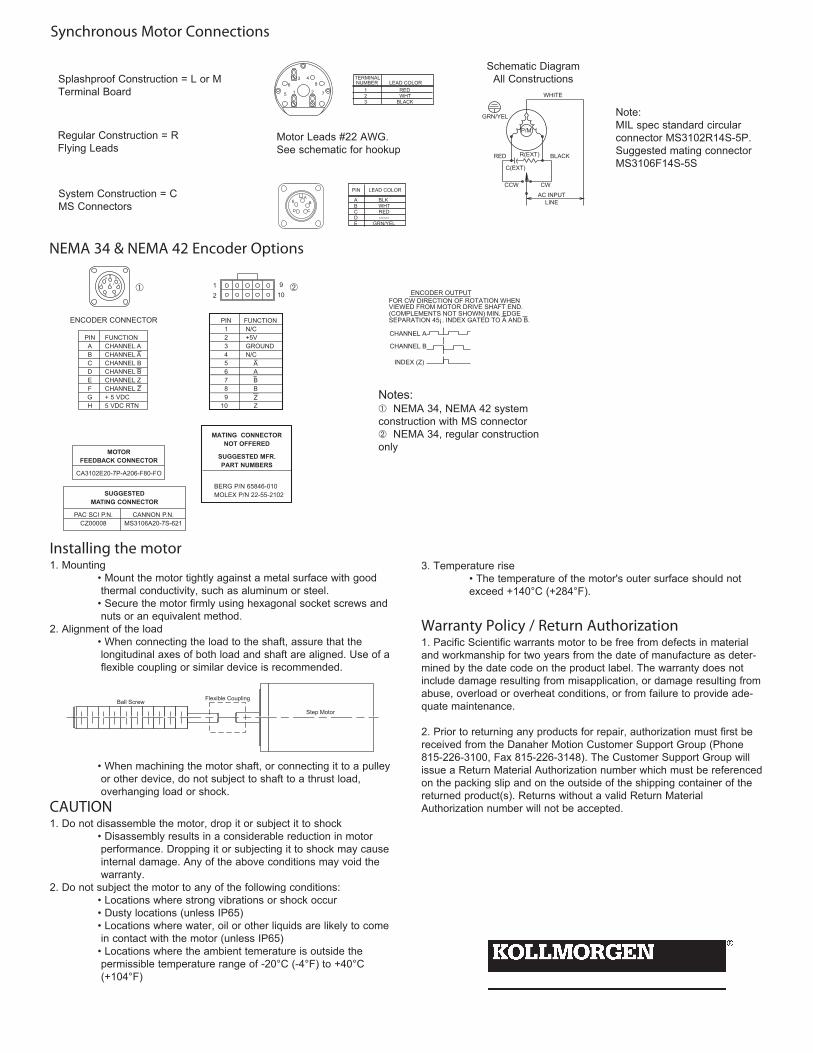
Installing the motor1. Mounting
• Mount the motor tightly against a metal surface with goodthermal conductivity, such as aluminum or steel.• Secure the motor firmly using hexagonal socket screws andnuts or an equivalent method.
2. Alignment of the load• When connecting the load to the shaft, assure that thelongitudinal axes of both load and shaft are aligned. Use of aflexible coupling or similar device is recommended.
Step Motor
Ball Screw Flexible Coupling
3. Temperature rise• The temperature of the motor's outer surface should notexceed +140°C (+284°F).
Warranty Policy / Return Authorization1. Pacific Scientific warrants motor to be free from defects in materialand workmanship for two years from the date of manufacture as deter-mined by the date code on the product label. The warranty does notinclude damage resulting from misapplication, or damage resulting fromabuse, overload or overheat conditions, or from failure to provide ade-quate maintenance.
2. Prior to returning any products for repair, authorization must first bereceived from the Danaher Motion Customer Support Group (Phone815-226-3100, Fax 815-226-3148). The Customer Support Group willissue a Return Material Authorization number which must be referencedon the packing slip and on the outside of the shipping container of thereturned product(s). Returns without a valid Return MaterialAuthorization number will not be accepted.
EA
B
CD
A BLK B WHT C RED D ------ E GRN/YEL
PIN LEAD COLOR
P/M
AC INPUTLINE
CWCCW
C(EXT)
R(EXT) BLACKRED
GRN/YEL
WHITE
63 4
8
7215 1 RED 2 WHT 3 BLACK
TERMINAL NUMBER LEAD COLOR
PIN FUNCTIONA CHANNEL AB CHANNEL AC CHANNEL BD CHANNEL BE CHANNEL ZF CHANNEL ZG + 5 VDCH 5 VDC RTN
ENCODER CONNECTOR
MOTORFEEDBACK CONNECTOR
CA3102E20-7P-A206-F80-FO
SUGGESTEDMATING CONNECTOR
PAC SCI P.N. CANNON P.N.CZ00008 MS3106A20-7S-621
E
G
D
A
F
B
CJK
PIN FUNCTION1 N/C2 +5V3 GROUND4 N/C5 A6 A7 B8 B9 Z
10 Z
MATING CONNECTORNOT OFFERED
SUGGESTED MFR.PART NUMBERS
BERG P/N 65846-010MOLEX P/N 22-55-2102
12
910 ENCODER OUTPUT
FOR CW DIRECTION OF ROTATION WHENVIEWED FROM MOTOR DRIVE SHAFT END.(COMPLEMENTS NOT SHOWN) MIN. EDGESEPARATION 45¡. INDEX GATED TO A AND B.
CHANNEL A
CHANNEL B
INDEX (Z)
Synchronous Motor Connections
NEMA 34 & NEMA 42 Encoder Options
Splashproof Construction = L or MTerminal Board
Regular Construction = RFlying Leads
System Construction = CMS Connectors
Motor Leads #22 AWG. See schematic for hookup
Schematic DiagramAll Constructions
Note:MIL spec standard circularconnector MS3102R14S-5P.Suggested mating connectorMS3106F14S-5S
Notes:NEMA 34, NEMA 42 system
construction with MS connectorNEMA 34, regular construction
only