Embed Size (px)
Citation preview
TRADE OF
Pipefitting
PHASE 2
Module 3
Pipe Processes
UNIT: 4
Pipe Preparation

Produced by
In cooperation with subject matter expert:
Finbar Smith
© SOLAS 2014
Module 3 – Unit 4
Pipefitting Phase 2
Pipe Preparation
Revision 2.0 September 2014
Table of Contents Unit Objective ........................................................................................................... 1 Learning Outcome .................................................................................................... 2 1.0 Material Inspection .................................................................................... 3
1.1 Material Inspection Responsibility .......................................................... 3 1.2 Material Inspection Procedures ............................................................... 3 1.3 Material Certification ................................................................................. 6 1.4 Material Defects ......................................................................................... 7
2.0 Calculate the Volume of Cylindrical Pipes and Vessels ....................... 8 2.1 Formulae for Volume Calculations ......................................................... 8
3.0 Pipe Cutting and Prepping Equipment ................................................... 10 3.1 Manual Pipe Cutting Equipment ............................................................. 10 3.2 Pipe Cutting Equipment ........................................................................... 11 3.3 Manual De-Burring Tool .......................................................................... 13 3.4 Pipe Prepping Equipment ........................................................................ 14
4.0 Hazards and Safety Precautions Associated with Pipe Cutting and Prepping Equipment ................................................................................. 15
4.1 General Safety Precautions for Pipe Cutting Equipment .................... 15 4.2 Safety Precautions for Operating an Orbital Saw ................................. 16
Exercises ..................................................................................................................... 18 Additional Resources ................................................................................................ 19
Module 3– Unit 4
Pipefitting Phase 2
1
Pipe Preparation
Revision 2.0 September 2014
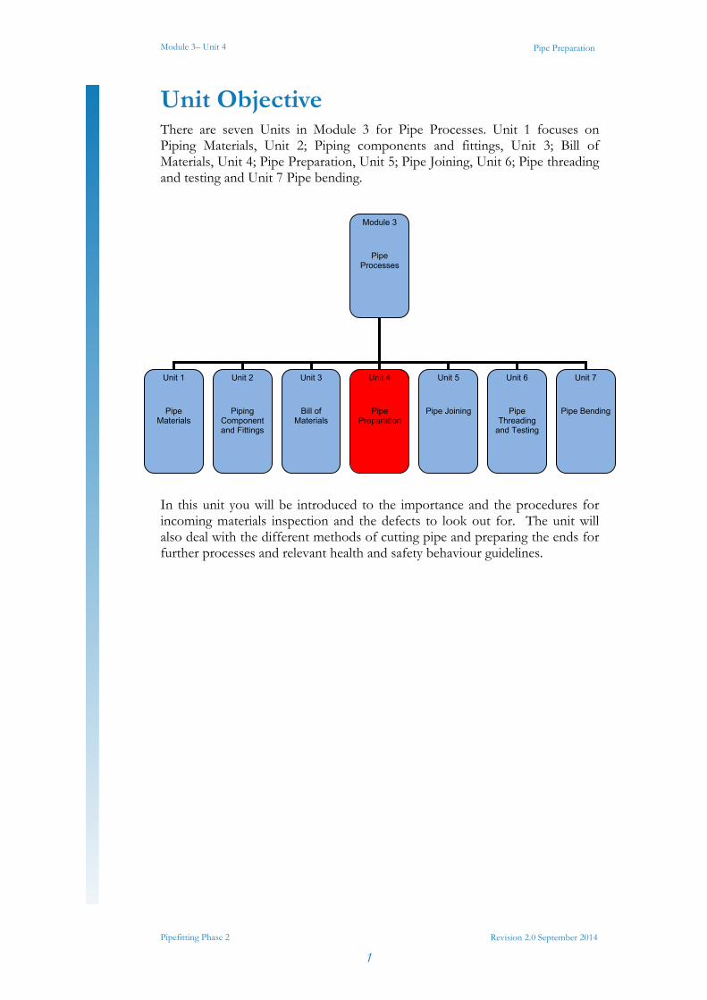
Unit Objective There are seven Units in Module 3 for Pipe Processes. Unit 1 focuses on Piping Materials, Unit 2; Piping components and fittings, Unit 3; Bill of Materials, Unit 4; Pipe Preparation, Unit 5; Pipe Joining, Unit 6; Pipe threading and testing and Unit 7 Pipe bending.
In this unit you will be introduced to the importance and the procedures for incoming materials inspection and the defects to look out for. The unit will also deal with the different methods of cutting pipe and preparing the ends for further processes and relevant health and safety behaviour guidelines.
Module 3
Pipe Processes
Unit 1
Pipe Materials
Unit 2
Piping Component and Fittings
Unit 3
Bill of Materials
Unit 4
Pipe Preparation
Unit 5
Pipe Joining
Unit 6
Pipe Threading
and Testing
Unit 7
Pipe Bending
Module 3– Unit 4
Pipefitting Phase 2
2
Pipe Preparation
Revision 2.0 September 2014
Learning Outcome By the end of this unit each apprentice will be able to:
Describe the procedure for material selection: a) Materials inspection
b) Defects
c) Specification
Calculate volume and capacity of pipes, cylinders and tanks.
Describe the various tools and equipment used in the preparation of pipe for jointing.
Select, measure, cut, ream and de burr mild steel piping using hacksaw, pipe cutters and pipe reamers.
Module 3– Unit 4
Pipefitting Phase 2
3
Pipe Preparation
Revision 2.0 September 2014
1.0 Material Inspection
1.1 Material Inspection Responsibility The first step to ensure the quality of the final product is to make sure that the incoming material being used meets the specified quality standards. To ensure that this happens there should be a procedure in place for the receipt, storage and issuing of materials, fittings and equipment irrespective of their point of origin. The procedure should also ensure that secure storage areas are provided for materials, fittings and that the issue and receipt of material is authorised and that control of stock quantities and quality are maintained. It is important that there are clearly defined roles of responsibility and that these roles are monitored and benchmarked against their required functions. For example the site store person should be responsible for the receipt, storage and issuing of materials at the site stores. The Project Manager should ensure that the above operation is controlled and that all procedures are followed and the quality of stock is maintained.
1.2 Material Inspection Procedures Storage areas should have restricted access so as to guarantee protection against physical damage and losses. Materials (raw materials used in the fabrication of pipework) will be stored separately from other construction materials and separate areas should be designated for different material types such as galvanised, carbon steel, and sanitary stainless steel pipe and fittings.
When operating a store the procedures should include at a minimum (but not be limited to) the following points:
All pipe fittings and installation equipment will, as far as possible, be kept in their original packaging. The cartons will be marked, such that the contents, quantity and size are easily identifiable.
Prior to being placed in storage, all material should be colour coded for ease of identification.
Black 304
Green 316
The colour coding shall be easily removable and shall not damage the material in any way.
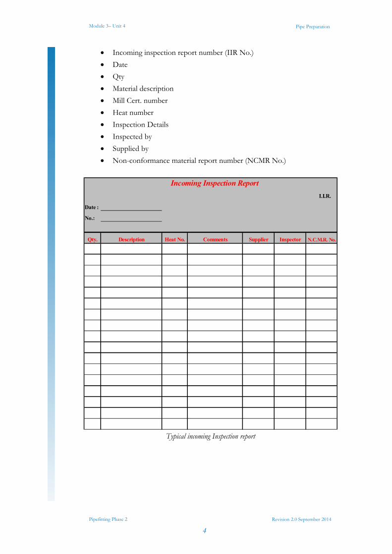
On receipt of materials the site store person shall complete an incoming inspection report (see typical incoming inspection report below ) and on this he / she shall record:
Key Learning Points Identify the key procedures for material inspection
Identify how material specifications are used to verify quality of incoming material
Identify possible material defects
Module 3– Unit 4
Pipefitting Phase 2
4
Pipe Preparation
Revision 2.0 September 2014
Incoming inspection report number (IIR No.)
Date
Qty
Material description
Mill Cert. number
Heat number
Inspection Details
Inspected by
Supplied by
Non-conformance material report number (NCMR No.)
Typical incoming Inspection report
Incoming Inspection Report
I.I.R.
Date :
No.:
Qty. Description Heat No. Comments Supplier Inspector N.C.M.R. No.
Module 3– Unit 4
Pipefitting Phase 2
5
Pipe Preparation
Revision 2.0 September 2014
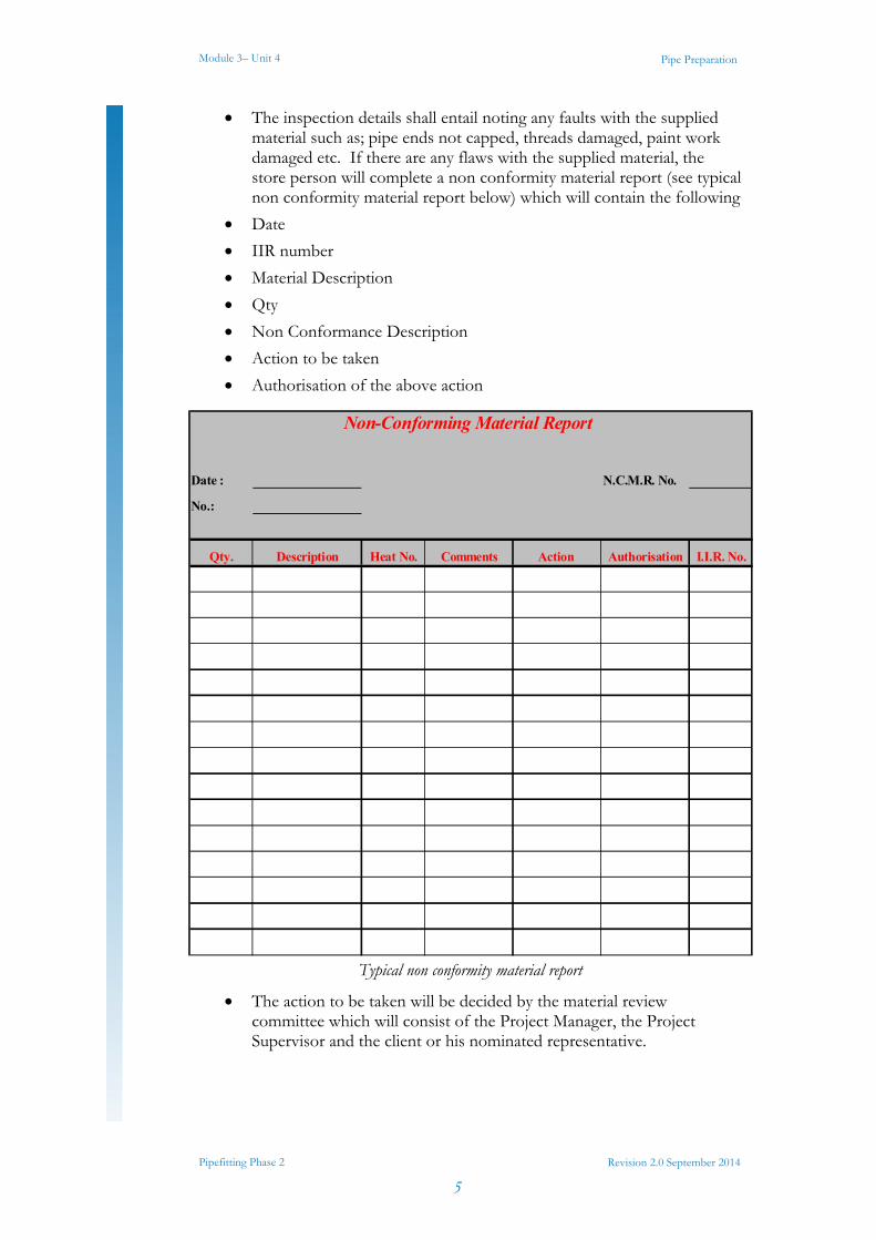
The inspection details shall entail noting any faults with the supplied material such as; pipe ends not capped, threads damaged, paint work damaged etc. If there are any flaws with the supplied material, the store person will complete a non conformity material report (see typical non conformity material report below) which will contain the following
Date
IIR number
Material Description
Qty
Non Conformance Description
Action to be taken
Authorisation of the above action
Typical non conformity material report
The action to be taken will be decided by the material review committee which will consist of the Project Manager, the Project Supervisor and the client or his nominated representative.
Non-Conforming Material Report
Date : N.C.M.R. No.
No.:
Qty. Description Heat No. Comments Action Authorisation I.I.R. No.
Module 3– Unit 4
Pipefitting Phase 2
6
Pipe Preparation
Revision 2.0 September 2014
A monthly inspection of all stock received by the stores will be conducted to ensure that equipment remains properly stored/protected and has not been damaged in any way. A record of this inspection will be retained for future reference.
The site store person is responsible for ensuring that any material returned to stores retains its traceability. Before the return of any material is accepted, it will be rigorously examined to ensure that there is no damage. If the material is damaged it will be deemed scrap. If not, a "return to stores" docket will be completed for the material or fittings. The docket will contain the following information:
Date
Job number
Quantity returned
Material description
Relevant ISO drawing number
Mill Cert. number
Heat number
Signature of person returning material
Signature of person receiving material
This docket shall be completed in duplicate
Original to stores
Copy to stock control
1.3 Material Certification More and more projects in industries such as pharmaceutical, power generation and oil and gas require full material certificates. These certificates provide full chemical composition of the material. There is a reference number on the certificate which is referred to by different names such as mill cert no., heat no., batch no. etc. This same number is etched or stamped on every component part that was made from this batch of material and ensures it’s traceability. When dealing with systems that require material traceability it is essential to verify that the material certificates have being received before installing the component in the system. During the validation phase components which do not have full certification must be removed and be replaced with certified components. This can prove very costly and cause huge time delays if only discovered at this stage.
Module 3– Unit 4
Pipefitting Phase 2
7
Pipe Preparation
Revision 2.0 September 2014
1.4 Material Defects When performing inspections for receipt of incoming materials the following important points should be noted:
Material matches specification for required materials
Quantity of materials matches delivery docket
Material certificates are present and heat numbers on fittings match the heat numbers on the certificates
Check the components for visual damage or rust
If components are individually packed then packaging should be sealed and undamaged.
For critical components such as orbital fittings dimensions and tolerances should be checked.
Module 3– Unit 4
Pipefitting Phase 2
8
Pipe Preparation
Revision 2.0 September 2014
2.0 Calculate the Volume of Cylindrical Pipes and Vessels
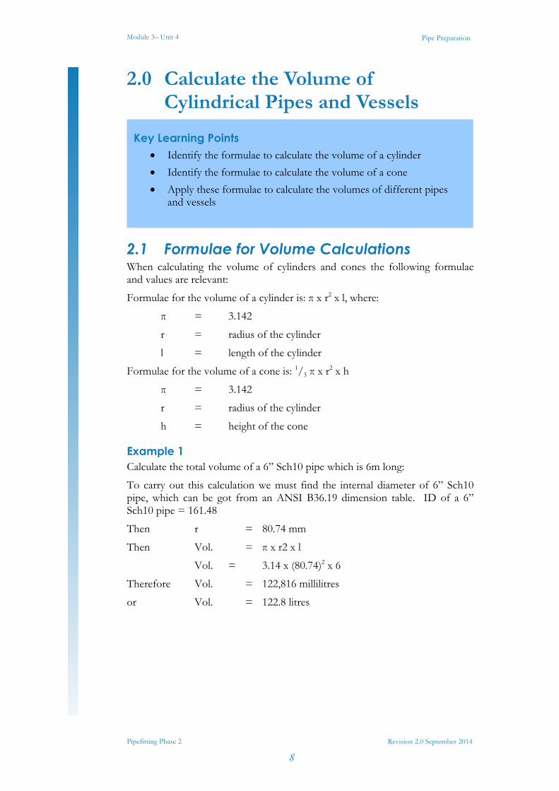
2.1 Formulae for Volume Calculations When calculating the volume of cylinders and cones the following formulae and values are relevant:
Formulae for the volume of a cylinder is: π x r2 x l, where:
π = 3.142
r = radius of the cylinder
l = length of the cylinder
Formulae for the volume of a cone is: 1/3 π x r2 x h
π = 3.142
r = radius of the cylinder
h = height of the cone
Example 1 Calculate the total volume of a 6” Sch10 pipe which is 6m long:
To carry out this calculation we must find the internal diameter of 6” Sch10 pipe, which can be got from an ANSI B36.19 dimension table. ID of a 6” Sch10 pipe = 161.48
Then r = 80.74 mm
Then Vol. = π x r2 x l
Vol. = 3.14 x (80.74)2 x 6
Therefore Vol. = 122,816 millilitres
or Vol. = 122.8 litres
Key Learning Points Identify the formulae to calculate the volume of a cylinder
Identify the formulae to calculate the volume of a cone
Apply these formulae to calculate the volumes of different pipes and vessels
Module 3– Unit 4
Pipefitting Phase 2
9
Pipe Preparation
Revision 2.0 September 2014
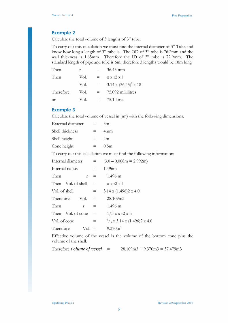
Example 2 Calculate the total volume of 3 lengths of 3” tube:
To carry out this calculation we must find the internal diameter of 3” Tube and know how long a length of 3” tube is. The OD of 3” tube is 76.2mm and the wall thickness is 1.65mm. Therefore the ID of 3” tube is 72.9mm. The standard length of pipe and tube is 6m, therefore 3 lengths would be 18m long
Then r = 36.45 mm
Then Vol. = π x r2 x l
Vol. = 3.14 x (36.45)2 x 18
Therefore Vol. = 75,092 millilitres
or Vol. = 75.1 litres
Example 3 Calculate the total volume of vessel in (m3) with the following dimensions:
External diameter = 3m
Shell thickness = 4mm
Shell height = 4m
Cone height = 0.5m
To carry out this calculation we must find the following information:
Internal diameter = (3.0 – 0.008m = 2.992m)
Internal radius = 1.496m
Then r = 1.496 m
Then Vol. of shell = π x r2 x l
Vol. of shell = 3.14 x (1.496)2 x 4.0
Therefore Vol. = 28.109m3
Then r = 1.496 m
Then Vol. of cone = 1/3 π x r2 x h
Vol. of cone = 1/3 x 3.14 x (1.496)2 x 4.0
Therefore Vol. = 9.370m3
Effective volume of the vessel is the volume of the bottom cone plus the volume of the shell:
Therefore volume of vessel = 28.109m3 + 9.370m3 = 37.479m3
Module 3– Unit 4
Pipefitting Phase 2
10
Pipe Preparation
Revision 2.0 September 2014
3.0 Pipe Cutting and Prepping Equipment
Note: It is important to segregate all cutting equipment that is used for ferrous materials from cutting equipment that is to be used on non-ferrous material. If ferrous cutting equipment is used on non-ferrous material such as stainless steel it can contaminate the parent material and cause discolouration and rusting.
3.1 Manual Pipe Cutting Equipment There are numerous tools used to manually cut pipe and the two most common pieces of equipment used are:
Tube guides and hacksaw
Pipe cutters
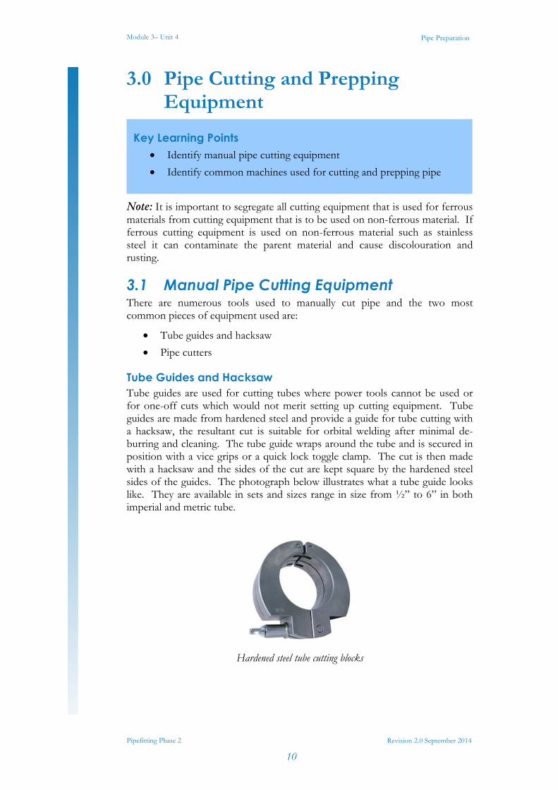
Tube Guides and Hacksaw Tube guides are used for cutting tubes where power tools cannot be used or for one-off cuts which would not merit setting up cutting equipment. Tube guides are made from hardened steel and provide a guide for tube cutting with a hacksaw, the resultant cut is suitable for orbital welding after minimal de-burring and cleaning. The tube guide wraps around the tube and is secured in position with a vice grips or a quick lock toggle clamp. The cut is then made with a hacksaw and the sides of the cut are kept square by the hardened steel sides of the guides. The photograph below illustrates what a tube guide looks like. They are available in sets and sizes range in size from ½” to 6” in both imperial and metric tube.
Hardened steel tube cutting blocks
Key Learning Points Identify manual pipe cutting equipment
Identify common machines used for cutting and prepping pipe
Module 3– Unit 4
Pipefitting Phase 2
11
Pipe Preparation
Revision 2.0 September 2014
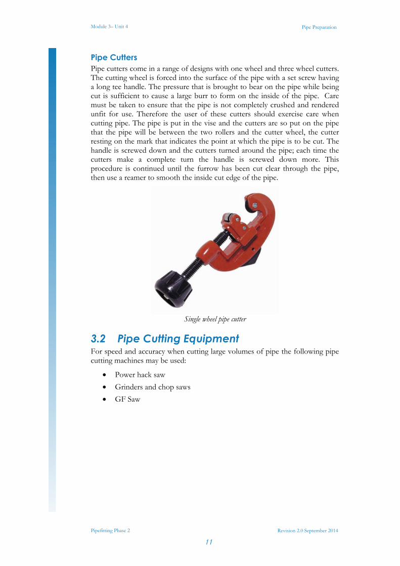
Pipe Cutters Pipe cutters come in a range of designs with one wheel and three wheel cutters. The cutting wheel is forced into the surface of the pipe with a set screw having a long tee handle. The pressure that is brought to bear on the pipe while being cut is sufficient to cause a large burr to form on the inside of the pipe. Care must be taken to ensure that the pipe is not completely crushed and rendered unfit for use. Therefore the user of these cutters should exercise care when cutting pipe. The pipe is put in the vise and the cutters are so put on the pipe that the pipe will be between the two rollers and the cutter wheel, the cutter resting on the mark that indicates the point at which the pipe is to be cut. The handle is screwed down and the cutters turned around the pipe; each time the cutters make a complete turn the handle is screwed down more. This procedure is continued until the furrow has been cut clear through the pipe, then use a reamer to smooth the inside cut edge of the pipe.
Single wheel pipe cutter
3.2 Pipe Cutting Equipment For speed and accuracy when cutting large volumes of pipe the following pipe cutting machines may be used:
Power hack saw
Grinders and chop saws
GF Saw
Module 3– Unit 4
Pipefitting Phase 2
12
Pipe Preparation
Revision 2.0 September 2014
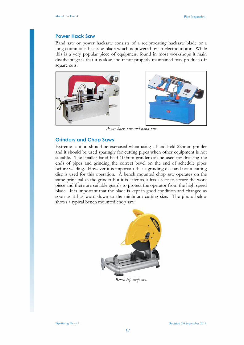
Power Hack Saw Band saw or power hacksaw consists of a reciprocating hacksaw blade or a long continuous hacksaw blade which is powered by an electric motor. While this is a very popular piece of equipment found in most workshops it main disadvantage is that it is slow and if not properly maintained may produce off square cuts.
Power hack saw and band saw
Grinders and Chop Saws Extreme caution should be exercised when using a hand held 225mm grinder and it should be used sparingly for cutting pipes when other equipment is not suitable. The smaller hand held 100mm grinder can be used for dressing the ends of pipes and grinding the correct bevel on the end of schedule pipes before welding. However it is important that a grinding disc and not a cutting disc is used for this operation. A bench mounted chop saw operates on the same principal as the grinder but it is safer as it has a vice to secure the work piece and there are suitable guards to protect the operator from the high speed blade. It is important that the blade is kept in good condition and changed as soon as it has worn down to the minimum cutting size. The photo below shows a typical bench mounted chop saw.
Bench top chop saw
Module 3– Unit 4
Pipefitting Phase 2
13
Pipe Preparation
Revision 2.0 September 2014
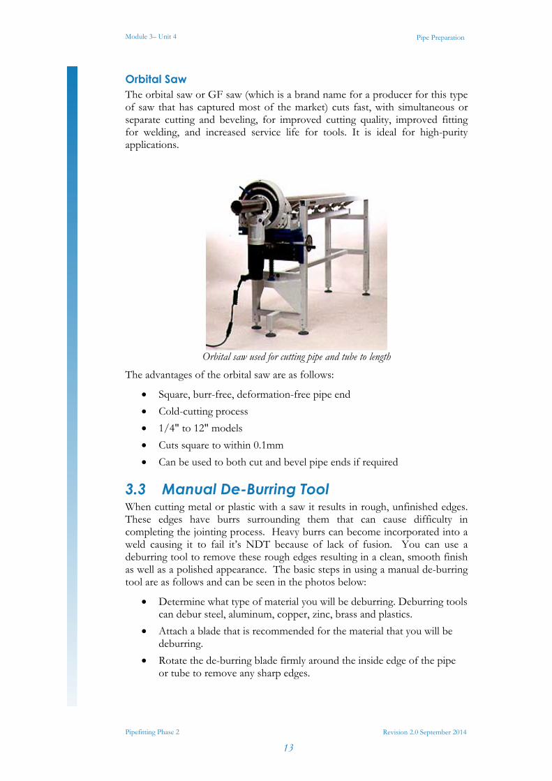
Orbital Saw The orbital saw or GF saw (which is a brand name for a producer for this type of saw that has captured most of the market) cuts fast, with simultaneous or separate cutting and beveling, for improved cutting quality, improved fitting for welding, and increased service life for tools. It is ideal for high-purity applications.
Orbital saw used for cutting pipe and tube to length
The advantages of the orbital saw are as follows:
Square, burr-free, deformation-free pipe end
Cold-cutting process
1/4" to 12" models
Cuts square to within 0.1mm
Can be used to both cut and bevel pipe ends if required
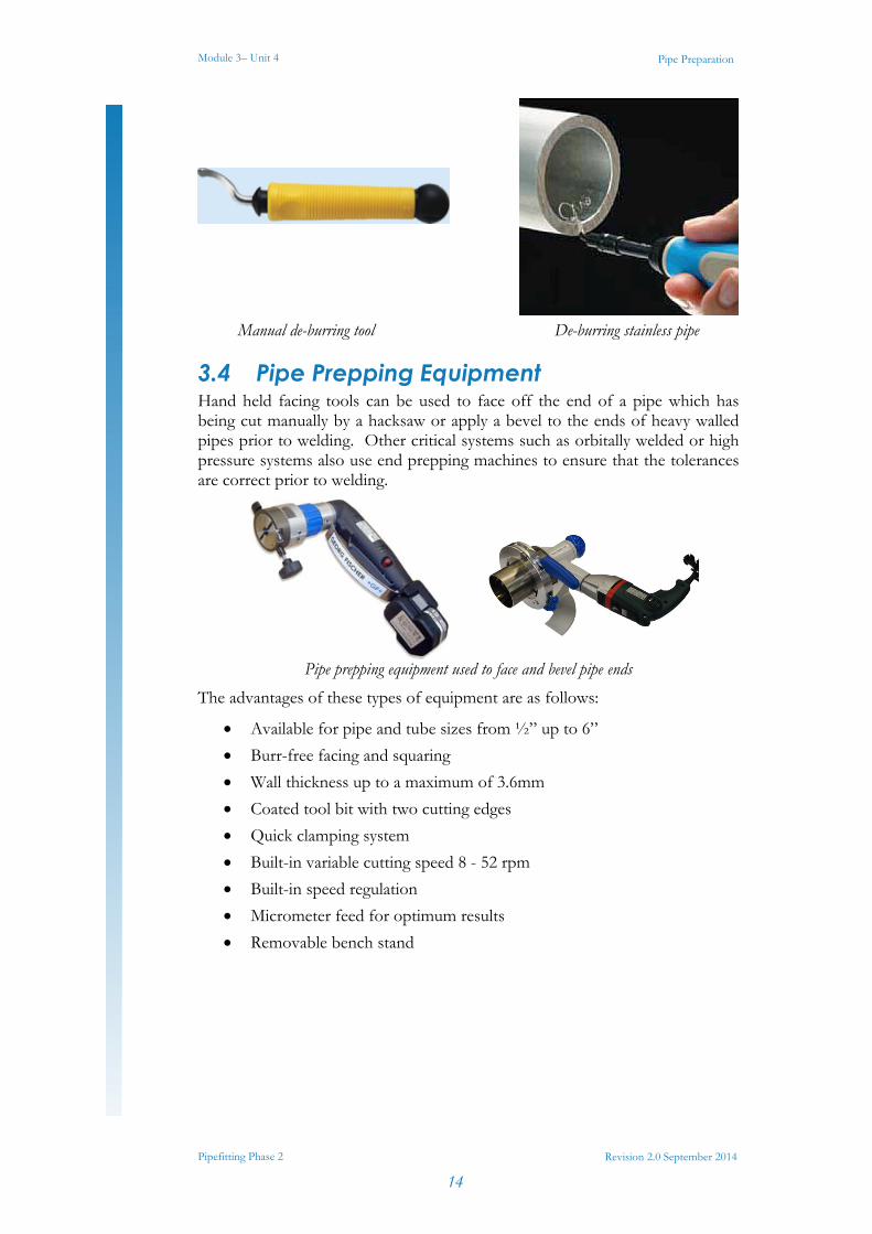
3.3 Manual De-Burring Tool When cutting metal or plastic with a saw it results in rough, unfinished edges. These edges have burrs surrounding them that can cause difficulty in completing the jointing process. Heavy burrs can become incorporated into a weld causing it to fail it’s NDT because of lack of fusion. You can use a deburring tool to remove these rough edges resulting in a clean, smooth finish as well as a polished appearance. The basic steps in using a manual de-burring tool are as follows and can be seen in the photos below:
Determine what type of material you will be deburring. Deburring tools can debur steel, aluminum, copper, zinc, brass and plastics.
Attach a blade that is recommended for the material that you will be deburring.
Rotate the de-burring blade firmly around the inside edge of the pipe or tube to remove any sharp edges.
Module 3– Unit 4
Pipefitting Phase 2
14
Pipe Preparation
Revision 2.0 September 2014
Manual de-burring tool De-burring stainless pipe
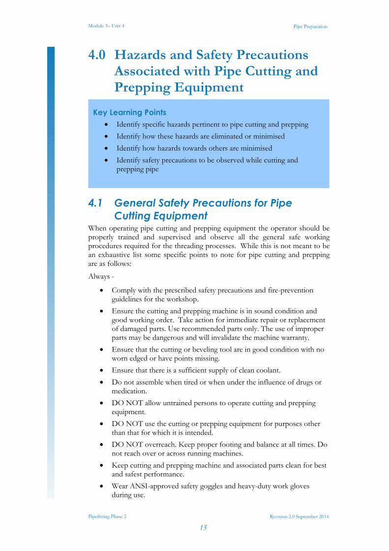
3.4 Pipe Prepping Equipment Hand held facing tools can be used to face off the end of a pipe which has being cut manually by a hacksaw or apply a bevel to the ends of heavy walled pipes prior to welding. Other critical systems such as orbitally welded or high pressure systems also use end prepping machines to ensure that the tolerances are correct prior to welding.
Pipe prepping equipment used to face and bevel pipe ends
The advantages of these types of equipment are as follows:
Available for pipe and tube sizes from ½” up to 6”
Burr-free facing and squaring
Wall thickness up to a maximum of 3.6mm
Coated tool bit with two cutting edges
Quick clamping system
Built-in variable cutting speed 8 - 52 rpm
Built-in speed regulation
Micrometer feed for optimum results
Removable bench stand
Module 3– Unit 4
Pipefitting Phase 2
15
Pipe Preparation
Revision 2.0 September 2014
4.0 Hazards and Safety Precautions Associated with Pipe Cutting and Prepping Equipment
4.1 General Safety Precautions for Pipe Cutting Equipment
When operating pipe cutting and prepping equipment the operator should be properly trained and supervised and observe all the general safe working procedures required for the threading processes. While this is not meant to be an exhaustive list some specific points to note for pipe cutting and prepping are as follows:
Always -
Comply with the prescribed safety precautions and fire-prevention guidelines for the workshop.
Ensure the cutting and prepping machine is in sound condition and good working order. Take action for immediate repair or replacement of damaged parts. Use recommended parts only. The use of improper parts may be dangerous and will invalidate the machine warranty.
Ensure that the cutting or beveling tool are in good condition with no worn edged or have points missing.
Ensure that there is a sufficient supply of clean coolant.
Do not assemble when tired or when under the influence of drugs or medication.
DO NOT allow untrained persons to operate cutting and prepping equipment.
DO NOT use the cutting or prepping equipment for purposes other than that for which it is intended.
DO NOT overreach. Keep proper footing and balance at all times. Do not reach over or across running machines.
Keep cutting and prepping machine and associated parts clean for best and safest performance.
Wear ANSI-approved safety goggles and heavy-duty work gloves during use.
Key Learning Points Identify specific hazards pertinent to pipe cutting and prepping
Identify how these hazards are eliminated or minimised
Identify how hazards towards others are minimised
Identify safety precautions to be observed while cutting and prepping pipe
Module 3– Unit 4
Pipefitting Phase 2
16
Pipe Preparation
Revision 2.0 September 2014
As with any machining process, there is a significant pinch hazard created. Keep hands, fingers, feet, and any item which may be injured or damaged away from the cutting and prepping machine during operation.
Ensure that there are no loose clothes to snag on rotating parts, that long hair is tied up and all jewelry is removed before commencing work.
Locate the cutting and prepping machine in a suitable, well lit working area.
Keep working area clean, tidy and free from unrelated materials.
Use on level and solid ground, preferably concrete.
Ensure all non-essential persons keep a safe distance whilst the cutting and prepping machine is in use.
4.2 Safety Precautions for Operating an Orbital Saw
The following are generic guidelines for orbital saw equipment, as there are many different suppliers of cutting equipment it is not possible to provide a specific check list. This information does not replace the manufacturer’s instruction guide, it is meant only to acquaint the operator with some basic functions and safety tips that he/she must be aware of.
Cutting equipment varies considerably in their control and safety arrangements and therefore it is important to verify that actual equipment used is set-up correctly.
Before each use, inspect the cutting equipment for damaged components.
Only use the pipe cutter for cutting and beveling operations as described in the operating manual and only use on the pipe and tube materials specified in the operation manual.
Do not use the pipe cutter unless all safety devises are working properly and the fixtures on the vise and base plate are fitted securely a) restart inhibitor
b) overload protection
c) saw blade guard
Check that correct blade is fitted for the material and pipe size to be cut.
Check that there are no teeth missing from the blade and that it is free from chips and dirt.
Disconnect the mains plug before fitting or changing the saw blade.
The inscription on the saw blade must always face the out towards the operator.
Regularly wipe down and clean the tool to keep it in best condition.
Module 3– Unit 4
Pipefitting Phase 2
17
Pipe Preparation
Revision 2.0 September 2014
Ensure that the saw blade is regularly lubricated with the correct cutting fluid. (Every 3 cuts is a good rule of thumb.)
Ensure that the speed settings are correct for the pipe size being cut.
Ensure that long lengths of pipe are properly supported on pipe rollers to prevent any strain on the orbital saw (Any pipe longer that 1m either side of the orbital saw should be supported.
Keep hands away from the cutting blade when in operation.
Raise the motor of the pipe cutter as if to start cutting, until the points of the saw blade teeth project about 1.5mm into the pipe.
Carefully turn the pipe cutter clockwise until the wall of the pipe has been pierced through. Continue to turn rapidly until the pipe has been cut off and the marks on the slide housing and vise housing are aligned.
Turn the pipe cutter back into its home position. Switch off the saw motor. Press the on/off switch again.
Gently tap the end of the pipe to remove any chips which may have entered the pipe during the cutting process.
Using a reamer or a had de-burring tool, remove the bur from the inside cut edge.
Ensure that the power cable does not become twisted or strained from the rotation of the cutting head as this will cause the cable to fail.
Check that keys and adjusting wrenches are removed from the tool or machine work surface before plugging it in.
Avoid unintentional starting. Be sure the switch is in the OFF position when not in use and before plugging in.
When not in use, store the tool in a clean, dry, safe location out of reach of children and other unauthorized persons.
Maintain product labels and nameplates. These carry important safety information.
Please refer to your instructor for specific instruction and additional safety information where required.
Module 3– Unit 4
Pipefitting Phase 2
18
Pipe Preparation
Revision 2.0 September 2014
Exercises Identify 2 common defects found on piping material components
What are heat numbers on piping components used for?
Calculate the total volume of a 12” Sch10 pipe which is 6m long:
Calculate the total volume (in litres) of a cone which has a base diameter of 500m and a height of 600mm:
Select, measure, cut, ream and debur mild steel piping using hacksaw, pipe cutters and pipe reamers.
Set up an orbital saw and cut 2” tube x 150mm long.
Module 3– Unit 4
Pipefitting Phase 2
19
Pipe Preparation
Revision 2.0 September 2014
Additional Resources Nayyar, P.E., Mohinder L. (2000). "A1". in Mohinder L. Nayyar, P.E..
Piping Handbook (7th ed.). New York: McGraw-Hill. ISBN 0-07-047106-1.
David L. Goetsch (2000). Technical Drawing (5th ed.). Thompson Delmar Learning ISBN: 1-4018-5760-4
International standard ISO 7-1: Pipe threads where pressure-tight joints are made on the threads — Part 1: Dimensions, tolerances and designation. International Organization for Standardization, Geneva.
BS EN 10226: Pipe threads where pressure tight joints are made on the threads. (The European version of ISO 7.)
Part 1: Taper external threads and parallel internal threads — Dimensions, tolerances and designation.
Part 2: Taper external threads and taper internal threads — Dimensions, tolerances and designation.
BS 21: Pipe threads for tubes and fittings where pressure-tight joints are made on the threads (metric dimensions). British Standards Institution, 1985. (Superseded by BS EN 10226:2004).
International standard ISO 228-1: Pipe threads where pressure-tight joints are not made on the threads — Part 1: Dimensions, tolerances and designation.
BS 2779: Specification for pipe threads for tubes and fittings where pressure-tight joints are not made on the threads (metric dimensions), 1986.
BS EN 10226-1:2004
ASME B31.9 Building Services Piping; 937 – Leak Testing, 1996 Edition
Elements of Plumbing by Samuel Edward Dibble, 2010

Castleforbes House Castleforbes Road
Dublin 1