Embed Size (px)
Citation preview
Motorized Ground ControlTM
Machine (worm gear) Screw Jack Operation & Maintenance Manual
413 Wacouta Street Suite #440St Paul, MN 55101PH: (651) 330-1263
www.arewindtowers.com
Revision G
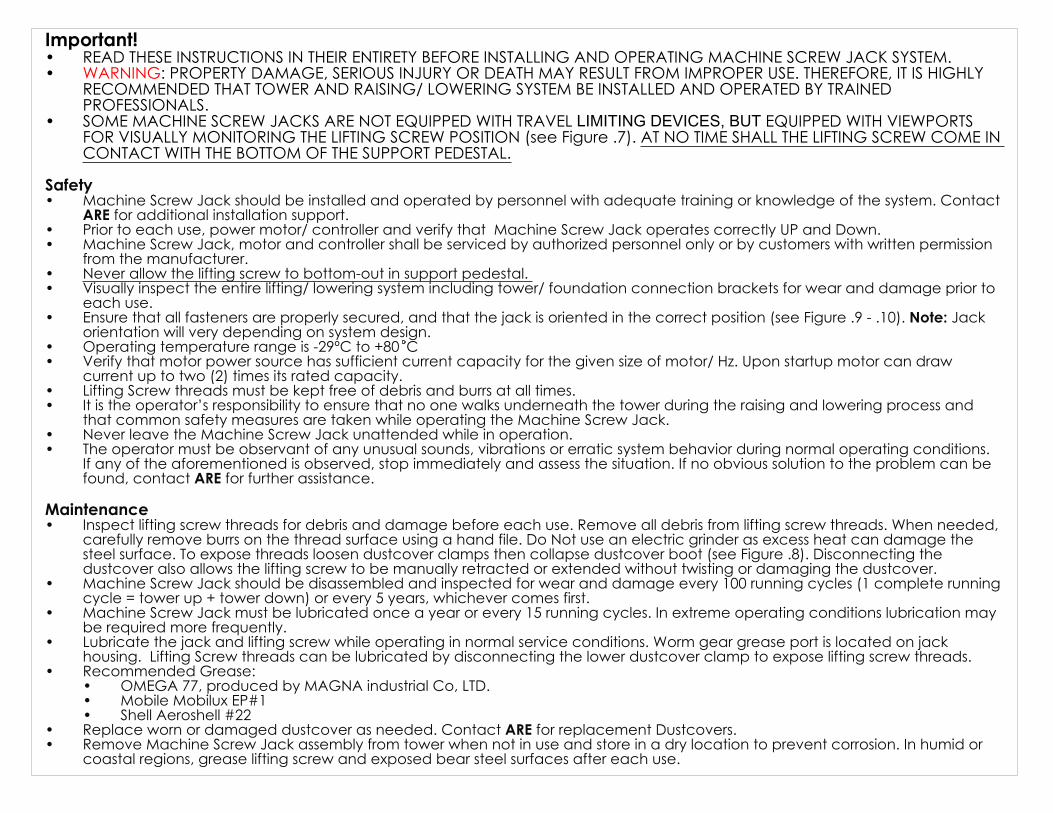
Important! READ THESE INSTRUCTIONS IN THEIR ENTIRETY BEFORE INSTALLING AND OPERATING MACHINE SCREW JACK SYSTEM.•WARNING: PROPERTY DAMAGE, SERIOUS INJURY OR DEATH MAY RESULT FROM IMPROPER USE. THEREFORE, IT IS HIGHLY •RECOMMENDED THAT TOWER AND RAISING/ LOWERING SYSTEM BE INSTALLED AND OPERATED BY TRAINED PROFESSIONALS.SOME MACHINE SCREW JACKS ARE NOT EQUIPPED WITH TRAVEL LIMITING DEVICES, BUT EQUIPPED WITH VIEWPORTS •FOR VISUALLY MONITORING THE LIFTING SCREW POSITION (see Figure .7). AT NO TIME SHALL THE LIFTING SCREW COME IN CONTACT WITH THE BOTTOM OF THE SUPPORT PEDESTAL.
Safety
Machine Screw Jack should be installed and operated by personnel with adequate training or knowledge of the system. Contact •ARE for additional installation support.Prior to each use, power motor/ controller and verify that Machine Screw Jack operates correctly UP and Down.•Machine Screw Jack, motor and controller shall be serviced by authorized personnel only or by customers with written permission •from the manufacturer.Never allow the lifting screw to bottom-out in support pedestal. •Visually inspect the entire lifting/ lowering system including tower/ foundation connection brackets for wear and damage prior to •each use.Ensure that all fasteners are properly secured, and that the jack is oriented in the correct position (see Figure .9 - .10). Note: Jack •orientation will very depending on system design. Operating temperature range is -29ºC to +80 C•Verify that motor power source has sufficient current capacity for the given size of motor/ Hz. Upon startup motor can draw •current up to two (2) times its rated capacity.Lifting Screw threads must be kept free of debris and burrs at all times.•It is the operator’s responsibility to ensure that no one walks underneath the tower during the raising and lowering process and •that common safety measures are taken while operating the Machine Screw Jack.Never leave the Machine Screw Jack unattended while in operation. •The operator must be observant of any unusual sounds, vibrations or erratic system behavior during normal operating conditions. •If any of the aforementioned is observed, stop immediately and assess the situation. If no obvious solution to the problem can be found, contact ARE for further assistance.
Maintenance
Inspect lifting screw threads for debris and damage before each use. Remove all debris from lifting screw threads. When needed, •carefully remove burrs on the thread surface using a hand file. Do Not use an electric grinder as excess heat can damage the steel surface. To expose threads loosen dustcover clamps then collapse dustcover boot (see Figure .8). Disconnecting the dustcover also allows the lifting screw to be manually retracted or extended without twisting or damaging the dustcover. Machine Screw Jack should be disassembled and inspected for wear and damage every 100 running cycles (1 complete running •cycle = tower up + tower down) or every 5 years, whichever comes first. Machine Screw Jack must be lubricated once a year or every 15 running cycles. In extreme operating conditions lubrication may •be required more frequently. Lubricate the jack and lifting screw while operating in normal service conditions. Worm gear grease port is located on jack •housing. Lifting Screw threads can be lubricated by disconnecting the lower dustcover clamp to expose lifting screw threads. Recommended Grease: •
OMEGA 77, produced by MAGNA industrial Co, LTD. •Mobile Mobilux EP#1 •Shell Aeroshell #22 •
Replace worn or damaged dustcover as needed. Contact ARE for replacement Dustcovers.•Remove Machine Screw Jack assembly from tower when not in use and store in a dry location to prevent corrosion. In humid or •coastal regions, grease lifting screw and exposed bear steel surfaces after each use.
2
1
9
4
38
6
7
Figure .2
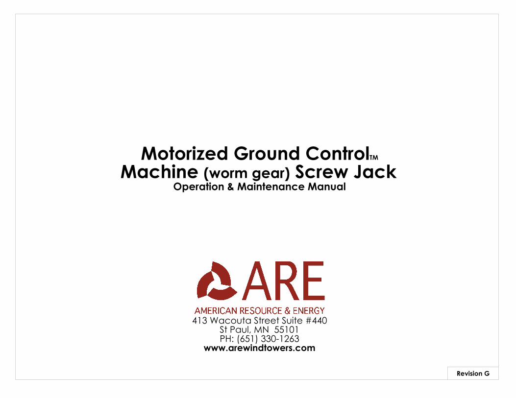
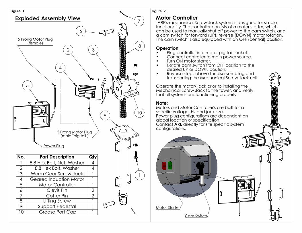
Motor Controller ARE's mechanical Screw Jack system is designed for simple functionality. The controller consists of a motor starter, which can be used to manually shut off power to the cam switch, and a cam switch for forward (UP), reverse (DOWN) motor rotation. The cam switch is also equipped with an OFF (central) position. Operation
Plug controller into motor pig tail socket.•Connect controller to main power source.•Turn ON motor starter.•Rotate cam switch from OFF position to the •desired UP or DOWN position.Reverse steps above for disassembling and •transporting the Mechanical Screw Jack unit
Operate the motor/ jack prior to installing the Mechanical Screw Jack to the tower, and verify that all systems are functioning properly.
Note:Motors and Motor Controller's are built for a specific voltage, Hz and jack size. Power plug configurations are dependent on global location or specification. Contact ARE directly for site specific system configurations.
10
5
5 Prong Motor Plug(female)
Power Plug
5 Prong Motor Plug(male "pig tail")
Motor Starter
Cam Switch
Figure .1
Exploded Assembly View
No. Part Description Qty1 8.8 Hex Bolt, Nut, Washer 4 2 8.8 Hex Bolt, Washer 43 Worm Gear Screw Jack 14 Geared Induction Motor 15 Motor Controller 16 Clevis Pin 27 Cotter Pin 28 Lifting Screw 19 Support Pedestal 110 Grease Port Cap 1
"E" typ
2
"A" Retracted
"C" 2X1
"B" Extended
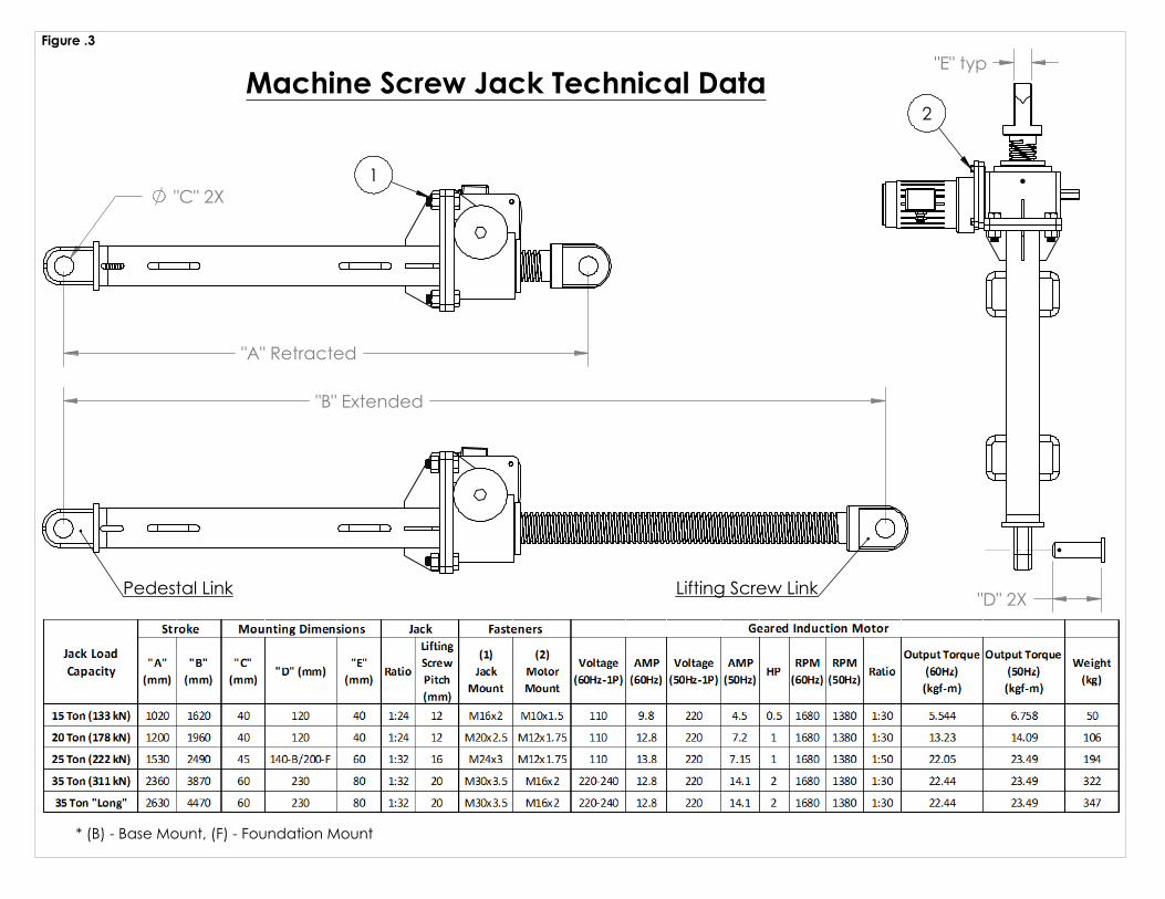
Figure .3
Machine Screw Jack Technical Data
Pedestal Link Lifting Screw Link "D" 2X
* (B) - Base Mount, (F) - Foundation Mount
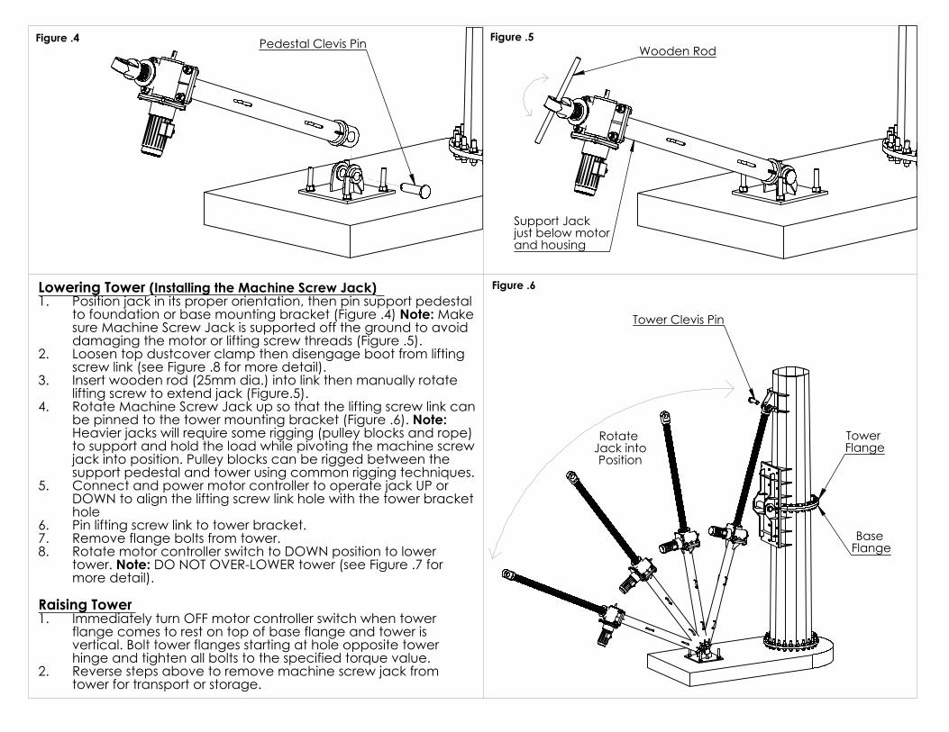
Lowering Tower (Installing the Machine Screw Jack) Position jack in its proper orientation, then pin support pedestal 1.to foundation or base mounting bracket (Figure .4) Note: Make sure Machine Screw Jack is supported off the ground to avoid damaging the motor or lifting screw threads (Figure .5).Loosen top dustcover clamp then disengage boot from lifting 2.screw link (see Figure .8 for more detail). Insert wooden rod (25mm dia.) into link then manually rotate 3.lifting screw to extend jack (Figure.5). Rotate Machine Screw Jack up so that the lifting screw link can 4.be pinned to the tower mounting bracket (Figure .6). Note: Heavier jacks will require some rigging (pulley blocks and rope) to support and hold the load while pivoting the machine screw jack into position. Pulley blocks can be rigged between the support pedestal and tower using common rigging techniques. Connect and power motor controller to operate jack UP or 5.DOWN to align the lifting screw link hole with the tower bracket holePin lifting screw link to tower bracket.6.Remove flange bolts from tower.7.Rotate motor controller switch to DOWN position to lower 8.tower. Note: DO NOT OVER-LOWER tower (see Figure .7 for more detail).
Raising Tower Immediately turn OFF motor controller switch when tower 1.flange comes to rest on top of base flange and tower is vertical. Bolt tower flanges starting at hole opposite tower hinge and tighten all bolts to the specified torque value. Reverse steps above to remove machine screw jack from 2.tower for transport or storage.
Figure .4
Figure .6
Pedestal Clevis Pin Wooden Rod
Support Jackjust below motorand housing
Figure .5
Tower Flange
Base Flange
Tower Clevis Pin
Rotate Jack intoPosition
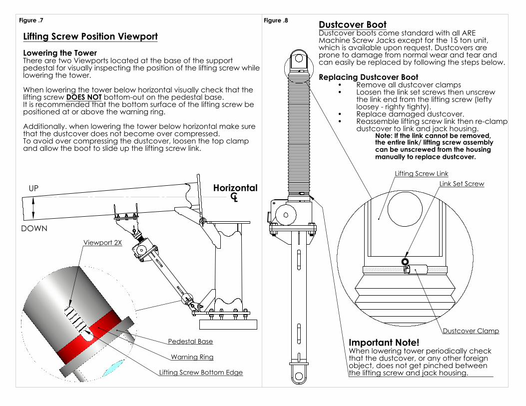
Figure .8
Important Note!When lowering tower periodically check that the dustcover, or any other foreignobject, does not get pinched between the lifting screw and jack housing.
Lifting Screw Position Viewport Lowering the Tower There are two Viewports located at the base of the supportpedestal for visually inspecting the position of the lifting screw while lowering the tower.
When lowering the tower below horizontal visually check that the lifting screw DOES NOT bottom-out on the pedestal base. It is recommended that the bottom surface of the lifting screw be positioned at or above the warning ring. Additionally. when lowering the tower below horizontal make sure that the dustcover does not become over compressed. To avoid over compressing the dustcover, loosen the top clamp and allow the boot to slide up the lifting screw link.
Figure .7
Dustcover Clamp
Link Set ScrewLifting Screw Link
Dustcover BootDustcover boots come standard with all ARE Machine Screw Jacks except for the 15 ton unit, which is available upon request. Dustcovers are prone to damage from normal wear and tear and can easily be replaced by following the steps below.
Replacing Dustcover BootRemove all dustcover clamps•Loosen the link set screws then unscrew •the link end from the lifting screw (lefty loosey - righty tighty).Replace damaged dustcover. •Reassemble lifting screw link then re-clamp •dustcover to link and jack housing.
Note: If the link cannot be removed,the entire link/ lifting screw assemblycan be unscrewed from the housing manually to replace dustcover.
HorizontalCL
UP
Pedestal Base
Lifting Screw Bottom Edge
Viewport 2X
Warning Ring
DOWN
RemovableTower Mounting
Bracket
BaseMountingBracket
Motor/Worm Gear
Axis
TowerHingeAxis
Figure .10 Base Mount
FixedTower Hinge
60mm MIN.75mm MAX.
Fixed TowerMountingBracket
A
Figure .9
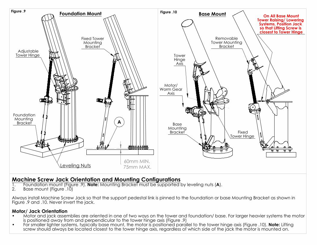
Machine Screw Jack Orientation and Mounting Configurations Foundation mount (Figure .9). Note: Mounting Bracket must be supported by leveling nuts (A). 1.Base mount (Figure .10) 2.
Always install Machine Screw Jack so that the support pedestal link is pinned to the foundation or base Mounting Bracket as shown in Figure .9 and .10. Never invert the jack.
Motor/ Jack OrientationMotor and jack assemblies are oriented in one of two ways on the tower and foundation/ base. For larger heavier systems the motor •is positioned away from and perpendicular to the tower hinge axis (Figure .9)For smaller lighter systems, typically base mount, the motor is positioned parallel to the tower hinge axis (Figure .10). Note: Lifting •screw should always be located closest to the tower hinge axis, regardless of which side of the jack the motor is mounted on.
FoundationMounting
Bracket
AdjustableTower Hinge
Foundation Mount
Leveling Nuts
On All Base MountTower Raising/ Lowering Systems, Position Jack so that Lifting Screw is closest to Tower Hinge