Embed Size (px)
Citation preview
Always consult Fuji before selling any Fuji equipment to a third party. Fuji reserves the right to change the contents or details given in this catalog without prior notification.
Headquarters / Okazaki Plant / Fujioka Plant
201601_general_ca_a4_e_01
www.fuji.co.jp
Headquarters19 Chausuyama, Yamamachi Chiryu, Aichi 472-8686 JAPANPhone : +81(566)81-2111 Fax : +81(566)81-8238
Machine Tool Division (Fujioka Plant)480 Tojiri, Hasama-cho, Toyota, Aichi 470-0452 JAPANPhone : +81(565)76-2211 Fax : +81(565)76-5413
Electronics Assembly Equipment Division (Okazaki Plant)1-3 Kitayoko, Eta-cho, Okazaki, Aichi 444-2107 JAPANPhone : +81(564)45-2000 Fax : +81(564)45-8816
Tokyo Branch Office6F Shinagawa Sankei Build. 2-4-15, Konan, Minato-ku, Tokyo 108-0075 JAPANPhone : +81(3)5460-0241 Fax : +81(3)5460-0250
Osaka Branch Office2F Esprit Esaka 1-17-26, Esakacho Suita, Osaka 564-0063 JAPANPhone : +81(6)6385-7904 Fax : +81(6)6368-106
Domestic SubsidiariesADTEK FUJI CO., LTD.74-1 Shaguchi, Nishihongo-cho, Okazaki, Aichi 444-0947 JAPANPhone : +81(564)31-4690 Fax : +81(564)31-1794
Overseas SubsidiariesUnited StatesChinaBrazilThailand Overseas Affiliates Germany
HungraySpainTurkeyCzechKorea
China
Thailand
India
FUJI MACHINE AMERICA CORP.KUNSHAN FUJI MACHINE MFG. CO., LTD.FUJI DO BRASIL MAQUINAS INDUSTRIAIS LTDA.FUJI MACHINE (THAILAND) CO., LTD.
Nomura Trading Co., Ltd. Hoomann Industrieausrustung GmbHM+E SZERSZAMGEP KERESKEDELMIKFTegasca s.aUNITEC Makine San. Imt. Ith. Ve Tic. A.S.Newtech s.r.o.DongWoo Trading CO., LTD.KI SUNG ENGINEERINGSEONGWON MACHINE CORP.SARA.TRADING CO.TRYTECH KOREA CO., LTD.
AnHui LinHong Mechanical Equipment Co. Ltd.DALIAN XINYU PRECISION MACHINE CO., LTD.Jinding Machinery Tech(SH) Co., Ltd.Kunshan Safety-Ctrl Development Equipment Co,.LtdM&G INTERNATIONAL TRADING(HK) LIMITEDMACHO INTERNATIONAL (HK) CO., LIMITEDNANJING WUYUE MACHINE CO., LTD.P&T MACHINERY INTERNATIONAL CO., LTD.PRO-TECHNIC MACHINERY LTD.SHANGHAI CHUKUMA MACHINE TOOL TRADE CO., LTD.TOP YI INTERNATIONAL TRADING(HK) LIMITEDWashin Tsusho Machinery CorporatioWUHAN SHIHUA TECHNIC LTD.YONGSHI INVESTIMENT TRADE(HONGKONG) CO., LTD.YUANRONG INTERNATIONAL HOLDINGS LIMITED
INUC SALES INTERNATIONAL CO., LTD.YUASA TRADING(THAILAND) CO., LTD.Proteck Machinary PVT. LTD.
Machine Tool
ISO 9001ISO 14001
Primary Business
Business EstablishedHeadquartersNumber of EmployeesManufacturing PlantsOverseas Bases
ISO/QS Certification
: Development, Manufacture, and Sales of Machine Tools: 1959: Toyota, Japan : 283 (2016/03) : 2-Fujioka, Kunshan: Chicago, USA /Sales and Service: Kunshan, China /Production, Sales and Service: ISO 9001, ISO 14001
SALES of Machine Tool Division
COMPANY PROFILE
FUJI robots lead the innovation
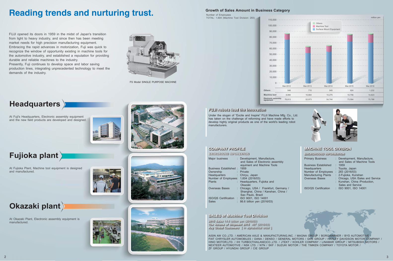
Growth of Sales Amount in Business Category
MACHINE TOOL DIVISION
Headquarters
Fujioka plant
Okazaki plant2015 Sales 14.6 billion yen (2016/03)The Volume of Shipment 2015 487 (2016/03)Key Global Customers [ In alphabetical order ]
AISIN AW CO.,LTD. / AMERICAN AXLE & MANUFACTURING,INC. / MAGNA GROUP / BORGWARNER / BYD AUTOMOTIVE / FIAT CHRYSLER AUTOMOBILES / DANA / DENSO / GENERAL MOTORS / GKN GROUP / HARLEY DAVIDSON MOTOR COMPANY / HINO MOTOR,LTD. / IHI TURBO(THAILAND)CO.,LTD. / JTEKT / KOHLER COMPANY / LINAMAR GROUP / MITSUBISHI MOTORS / NEXTEER AUTOMOTIVE / NSK LTD. / NTN / SKF / SUZUKI MOTOR / THE TIMKEN COMPANY / TOYOTA MOTOR / ZF GROUP / HYUNDAI GROUP / CIE GROUP
BACKGROUND INFORMATION BACKGROUND INFORMATION
million yen
90,000
80,000
70,000
60,000
50,000
40,000
30,000
20,000
10,000
0
100,000
110,000
Others
Machine toolElectronic assemblyeguipment
FS Model SINGLE PURPOSE MACHINE
2 3
Mar.2012
546
8,890
76,813
Mar.2013
710
10,664
52,973
Mar.2014
545
10,275
54,744
Mar.2015
924
10,756
73,584
Mar.2016
1,232
14,623
70,786
Under the slogan of “Excite and Inspire” FUJI Machine Mfg. Co., Ltd. has taken on the challenge of reforming and have made efforts to develop highly original products as one of the world’s leading robot manufacturers.
FUJI opened its doors in 1959 in the midst of Japan's transition from light to heavy industry, and since then has been meeting market needs for high precision manufacturing equipment. Embracing the rapid advances in motorization, Fuji was quick to recognize the window of opportunity existing in machine tools for the automotive industry, and established a reputation for providing durable and reliable machines to the industry. Presently, Fuji continues to develop space and labor saving production lines, integrating unprecedented technology to meet the demands of the industry.
At Fuji's Headquarters, Electronic assembly equipment and the new field products are developed and designed.
At Fujioka Plant, Machine tool equipment is designed and manufactured.
At Okazaki Plant, Electronic assembly equipment is manufactured.
Major business
Business EstablishedOwnershipHeadquartersNumber of EmployeesPlants
Overseas Bases
ISO/QS CertificationSales
: Development, Manufacture, and Sales of Electronic assembly equiment and Machine Tools: 1959: Private: Chiryu, Japan: 1,604 (2016/03): Headquarters, Fujioka and Okazaki: Chicago, USA / Frankfurt, Germany / Shanghai, China / Kanshan, China / Sao Paulo, Brazil: ISO 9001, ISO 14001: 86.6 billion yen (2016/03)
OthersMachine ToolSurface Mount Equipment
Number of EmployeesTOTAL: 1,604 (Machine Tool Division: 283)
Reading trends and nurturing trust.
4 5
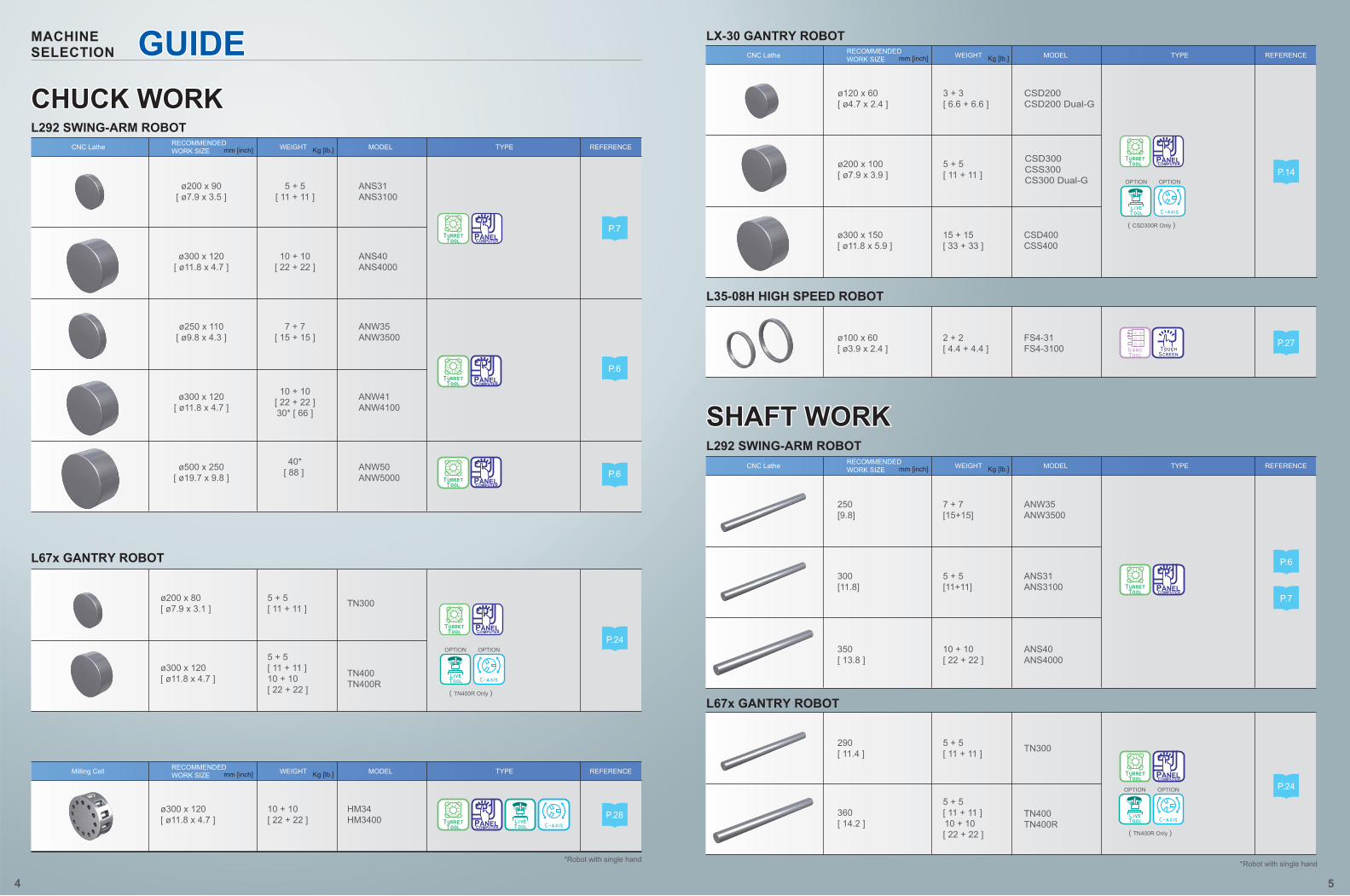
MACHINESELECTION
CHUCK WORKCHUCK WORK
SHAFT WORKSHAFT WORK
ø300 x 120[ ø11.8 x 4.7 ]
5 + 5[ 11 + 11 ]10 + 10[ 22 + 22 ]
TN400TN400R
*Robot with single hand
ø200 x 90[ ø7.9 x 3.5 ]
5 + 5[ 11 + 11 ]
ANS31ANS3100
ø300 x 120[ ø11.8 x 4.7 ]
10 + 10[ 22 + 22 ]
ANS40ANS4000
ø250 x 110[ ø9.8 x 4.3 ]
7 + 7[ 15 + 15 ]
ANW35ANW3500
ø300 x 120[ ø11.8 x 4.7 ]
10 + 10[ 22 + 22 ]30* [ 66 ]
ANW41ANW4100
ø500 x 250[ ø19.7 x 9.8 ]
40*[ 88 ] ANW50
ANW5000
L292 SWING-ARM ROBOT
L67x GANTRY ROBOT
REFERENCETYPEMODELWEIGHT Kg [lb.]mm [inch]RECOMMENDEDWORK SIZECNC Lathe
REFERENCETYPEMODELWEIGHT Kg [lb.]mm [inch]RECOMMENDEDWORK SIZECNC Lathe
REFERENCETYPEMODELWEIGHT Kg [lb.]mm [inch]RECOMMENDEDWORK SIZECNC Lathe
REFERENCETYPEMODELWEIGHT Kg [lb.]mm [inch]RECOMMENDEDWORK SIZEMilling Cell
OPTION OPTION
( TN400R Only )
P.6
ø200 x 80[ ø7.9 x 3.1 ]
5 + 5[ 11 + 11 ] TN300
ø300 x 120[ ø11.8 x 4.7 ]
10 + 10[ 22 + 22 ]
HM34HM3400
ø100 x 60[ ø3.9 x 2.4 ]
2 + 2[ 4.4 + 4.4 ]
FS4-31FS4-3100
ø120 x 60[ ø4.7 x 2.4 ]
3 + 3[ 6.6 + 6.6 ]
CSD200CSD200 Dual-G
ø300 x 150[ ø11.8 x 5.9 ]
15 + 15[ 33 + 33 ]
CSD400CSS400
250[9.8]
7 + 7[15+15]
ANW35ANW3500
300[11.8]
5 + 5[11+11]
ANS31ANS3100
*Robot with single hand
L67x GANTRY ROBOT
LX-30 GANTRY ROBOT
L292 SWING-ARM ROBOT
L35-08H HIGH SPEED ROBOT
290[ 11.4 ]
5 + 5[ 11 + 11 ] TN300
360[ 14.2 ]
5 + 5[ 11 + 11 ]10 + 10[ 22 + 22 ]
TN400TN400R
ø200 x 100[ ø7.9 x 3.9 ]
5 + 5[ 11 + 11 ]
CSD300CSS300CS300 Dual-G
P.7
P.27
P.6
P.7
P.24
P.14
P.6
P.24
P.28
350[ 13.8 ]
10 + 10[ 22 + 22 ]
ANS40ANS4000
GUIDECHUCK WORK
SHAFT WORK
OPTION OPTION
( TN400R Only )
OPTION OPTION
( CSD300R Only )
work area
handling area cutting area
Interrupted cutting steel Finishing of aluminum
5
ø60ø60
4.5μm 1.5μm
6 7
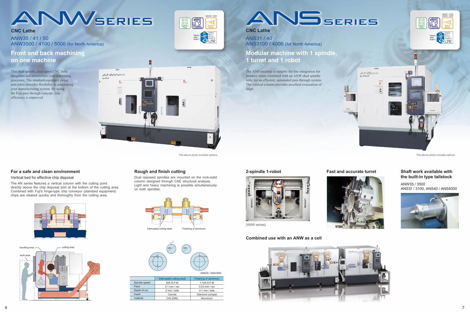
ANW35 / 41 / 50ANW3500 / 4100 / 5000 (for North America)
For a safe and clean environmentVertical bed for effective chip disposal
ANW35 / ANW3500
CNC LatheANS31 / 40ANS3100 / 4000 (for North America)
CNC Lathe
2-spindle 1-robot
825 R.P.MSpindle speed 1,100 R.P.M0.1 mm / revFeed 0.03 mm / rev2 mm / sideDepth of cut 0.1 mm / side
CermetInsert Diamond compaxC45 (DIN)material Aluminum
Interrupted cutting steel Finishing of aluminum
Fast and accurate turret
The above photo includes options. The above photo includes options.
(ANW series)
Shaft work available with the built-in type tailstockANW35 / 3500 ANS31 / 3100, ANS40 / ANS4000
ANS31 / 3100ANS40 / 4000ANW35 / 3500
Front and back machining on one machine
Modular machine with 1 spindle,1 turret and 1 robot
This dual spindle, dual turret CNC lathe integrates and streamlines your machining processes. The standard-equipped swing arm robot provides flexibility in automating your manufacturing system. By using the Fuji pass through concept, line efficiency is improved.
The ANS machine is suitable for line integration for instance when combined with an ANW-dual spindle lathe for an efficient, automated pass through system.The vertical column provides excellent evacuation of chips.
The AN series features a vertical column with the cutting point directly above the chip disposal port at the bottom of the cutting area. Combined with Fuji's hinge-type chip conveyor (standard equipment) chips are cleared quickly and thoroughly from the cutting area.
Rough and finish cuttingDual opposed spindles are mounted on the rock-solid column designed through CAE structural analysis. Light and heavy machining is possible simultaneously on both spindles.
Combined use with an ANW as a cell
Specifications are subject to change without notice.
[ mm ]
200
300
500
250
106110
7876
8
9595
200
200
110 110
250
250
120 120
300
9
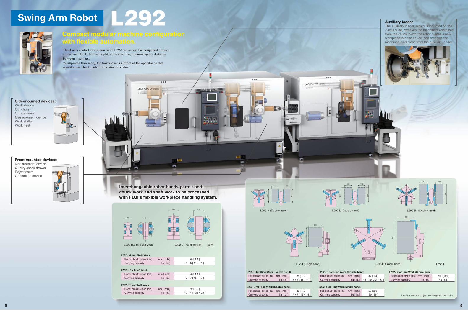
The 4-axis control swing-arm robot L292 can access the peripheral devices at the front, back, left, and right of the machine, minimizing the distance between machines.Workpieces flow along the traverse axis in front of the operator so that operator can check parts from station to station.
Compact modular machine configuration with flexible automation.
Front-mounted devices:Measurement deviceQuality check drawerReject chuteOrientation device
Side-mounted devices:Work stockerOut chuteOut conveyorMeasurement deviceWork shifterWork nest
Auxiliary loaderThe auxiliary loader, which is mounted on the Z-axis slide, removes the machined workpiece from the chuck. Next, the robot places a new workpiece into the chuck, and receives the machined workpiece from the auxiliary loader.
L292-H (Double hand) L292-B1 (Double hand)
L292-J (Single hand) L292-G (Single hand)
L292-L (Double hand)
L292-H,L for shaft work [ mm ]L292-B1 for shaft work
Interchangeable robot hands permit both chuck work and shaft work to be processed with FUJI’s flexible workpiece handling system.
28 [ 1.1 ]Robot chuck stroke (dia)5 + 5 [ 11 + 11 ]Carrying capacity
mm [ inch ]kg [ lb. ]
L292-H/L for Shaft Work
28 [ 1.1 ]Robot chuck stroke (dia)7 + 7 [ 15 + 15 ]Carrying capacity
mm [ inch]kg [ lb. ]
L292-L for Shaft Work
50 [ 2.0 ]Robot chuck stroke (dia)10 + 10 [ 22 + 22 ]Carrying capacity
mm [ inch ]kg [ lb. ]
L292-B1 for Shaft Work
25 [ 1.0 ]Robot chuck stroke (dia)5 + 5 [ 11 + 11 ]Carrying capacity
mm [ inch ]kg [l b. ]
L292-H for Ring Work (Double hand)
25 [ 1.0 ]Robot chuck stroke (dia)7 + 7 [ 15 + 15 ]Carrying capacity
mm [ inch ]kg [ lb. ]
L292-L for Ring Work (Double hand)
30 [ 1.2 ]Robot chuck stroke (dia)10 + 10 [2 2 + 22 ]Carrying capacity
mm [ inch ]kg [ lb. ]
L292-B1 for Ring Work (Double hand)
50 [ 2.0 ]Robot chuck stroke (dia)30 [ 66 ]Carrying capacity
mm [ inch ]kg [ lb. ]
L292-J for RingWork (Single hand)
100 [ 3.9 ]Robot chuck stroke (dia)40 [ 88 ]Carrying capacity
mm [ inch ]kg [ lb. ]
L292-G for RingWork (Single hand)
Swing Arm Robot
10 11
ANW series ANS series
Machine Specifications
Specifications for ANW series
Recommended work sizeSpindle diaSpindle noseSpindle boreSpindle speedSpindle motorNumber of tool stationsTurret index timeTurret mechanism Chuck sizeCNC control
FootprintMachine heightMachine weight
3490 x 1955 [ 11'5'' x 6'5'' ]2310 [ 7'7'' ]
8500 [ 18700 ]
3570 x 2105 [ 11'9'' x 6'11'' ]2420 [ 7'11'' ]9000 [ 19800 ]
4700 x 2645 [ 15'5'' x 8'8'' ]2980 [ 9'9'' ]
12000 [ 26400 ]
mm x mm [ feet, inch x feet, inch ]mm [ feet, inch ]
kg [ lb. ]
Slide stroke
Feed motor
mm [ inch ]mm [ inch ]
mm [ inch ]min-1
kw [ hp ]
sec
inch
mm [ inch ]mm [ inch ]
kw [ hp ]kw [ hp ]
X-axisZ-axisX-axisZ-axis
ø250 x 110 [ ø9.8 x 4.3 ]ø100 [ ø3.9 ]
A2-6ø56 [ ø2.2 ]Max. 3500
15 / 18.5 [ 20 / 25 ]8 + 80.4
Cam8~10
FANUC 0i-TD225 [ 8.86 ]
405 [ 15.94 ]3.0 [ 4.0 ]3.0 [4.0]
ø300 x 120 [ ø11.8 x 4.7 ]ø120 [ ø4.7 ]
A2-8ø67 [ ø2.6 ]Max. 3000
18.5 / 22 [ 25 / 30 ]12 + 12
1.2Two piece coupling
10~12FANUC 0i-TD265 [ 10.43 ]455 [ 17.91]
4.0 [ 5.4 ]4.0 [ 5.4 ]
ø500 x 250 [ ø19.7 x 9.8 ]ø150 [ ø5.9 ]
A2-11ø67 [ ø2.6 ]Max. 2500
30 / 37 [ 40 / 50 ]10 + 10
1.0Two piece coupling
15FANUC 0i-TD345 [ 13.58 ]700 [ 27.56 ]
4.0 [ 5.4 ]4.0 [ 5.4 ]
ANW35 / 3500
Max.work lengthCenter built-in typeQuill strokeQuill dia
250 [ 9.8 ]MT.4
130 [ 5.1 ]ø100 [ ø3.9 ]
mm [ inch ]
mm [ inch ]mm [ inch ]
ANW35 / 3500
ANW41 / 4100Machine Specifications
Recommended work sizeSpindle diaSpindle noseSpindle boreSpindle speedSpindle motorNumber of tool stationsTurret index timeTurret mechanism Chuck size
RobotCarrying capacityRobot controller
FootprintMachine heightMachine weight
mm x mm [ feet, inch x feet, inch ]mm [ feet, inch ]
kg [ lb. ]
1750 x 1906 [ 5'9" x 6'3" ]2260 [ 7'5" ]
3500 [ 7700 ]
1850 x 2106 [ 6'1" x 6'11" ]2420 [ 7'11" ]4000 [ 8800 ]
L292-H5 + 5 [ 11 + 11 ]
MAX SP1
L292-B110 + 10 [ 22 + 22 ]
MAX SP1
CNC control
Slide stroke
Feed motor
mm [ inch ]mm [ inch ]
mm [ inch ]r.p.m
kw [ hp ]
sec
inch
mm [ inch ]mm [ inch ]
kw [ hp ]kw [ hp ]
X-axisZ-axisX-axisZ-axis
ø200 x 90 [ ø7.9 x 3.5 ]ø100 [ ø3.9 ]
A2-6ø56 [ ø2.2 ]Max. 3500
11 / 15 [ 15 / 20 ]8
0.4Cam
8~10FANUC 0i-TD
225 [ 8.86 ]465 [ 18.31 ]
3.0 [ 4.0 ]3.0 [ 4.0 ]
ø300 x 120 [ ø11.8 x 4.7 ]ø120 [ ø4.7 ]
A2-8ø67 [ ø2.6 ]Max. 3000
18.5 / 22 [ 25 / 30 ]121.2
Two piece coupling10~12
FANUC 0i-TD265 [ 10.43 ]445 [ 17.52 ]
4.0 [ 5.4 ]4.0 [ 5.4 ]
ANS31 / 3100
Max. work lengthCenter built-in typeQuill strokeQuill dia
mm [ inch ]
mm [ inch ]mm [ inch ]
300 [ 11.8 ]MT.4
130 [ 5.12 ]ø100 [ 3.9 ]
ANS31 / 3100350 [ 13.8 ]
MT.4 130 [ 5.12 ]ø100 [ 3.9 ]
ANS40 / 4000
ANS40 / 4000ANW50 / 5000
Machine Specifications with Tailstock
Specifications for ANS series
Work example
In-process auto gauging system for accurate off-setting (option).
ANW series line up ANS series line up
Robot Specifications
Robot
Carrying capacity
Robot controller
L292-L
7 + 7 [ 15 + 15 ]
MAX SP1
L292-G
40 [ 88 ]
MAX SP1
L292-B1option : L292-J
10 + 10 [ 22 + 22 ]option: 30 [ 66 ]
MAX SP1
kg [ lb. ]
Machine Size
Machine Specifications with Tailstock
Specifications are subject to change without notice.Specifications are subject to change without notice.
Robot Specifications
kg [ lb. ]
Machine Size
Size.unit: m2 [ f t2 ]
Size.unit: m2 [ f t 2 ]6.8 [ 73 ] 7.5 [ 80 ] 12.4 [ 133 ]
ANW41ANW4100
ANW50ANW5000
ø300[ ø11.8 ]
ø250[ ø9.8 ]
Machining dia.unit: mm [ inch ]
Machining dia.unit: mm [ inch ]
ø500[ ø19.7 ]
ANW35ANW3500
3.3 [ 35 ] 3.9 [ 42 ]
ANS31 / 3100Max length 300 [ 11.8 ]
ANS40 / 4000Max length 350 [ 13.8 ]
ANS31ANS3100
ANS40ANS4000
ø40 [ ø1.6 ]
ø75 [ ø3 ]
ø200 [ ø7.9 ]
ø300 [ ø11.8 ]
ANS31PANS3100PHigh rigid and accurate turning machine for completes hard turning process.Efficient designed rigid machine base for ultimate hard-turn durability.C-3 spacer ball system is used for the x-axis ball screw.
(for North America)
The above photo includes options.
SIDE GEAR HUB FRONT AXLE DRIVE PINION SHAFT GEAR COUNTER DRIVE GEAR DIFFERENTIAL RING
12 13
Main Screen
Touch Screen Operation Panel
The maintenance tool and quality check counters are installed on the screen.
Superb graphics for ease of data recognition and operation.
Each function and commmand can be seen on the screen. No need to look up the control diagram.
Sub Screens
The new operation panel has expanded features and is user friendly.
Touch the menu button twiceto get to pop-up menu
Illuminated for easy visual identification
Indicates the current machine conditionat machine start up
color monitor responds quickly to the selections made by light touching of the screen, making it convenient and easy to operate.
One touch confirmation of current set-up.
Monitors current conditionwithout looking at prints.
Quality Check Counter Tool Counter / Offset
Sequence Parameter Check I/O Check Screen
Panel Computer
Operation Pendant
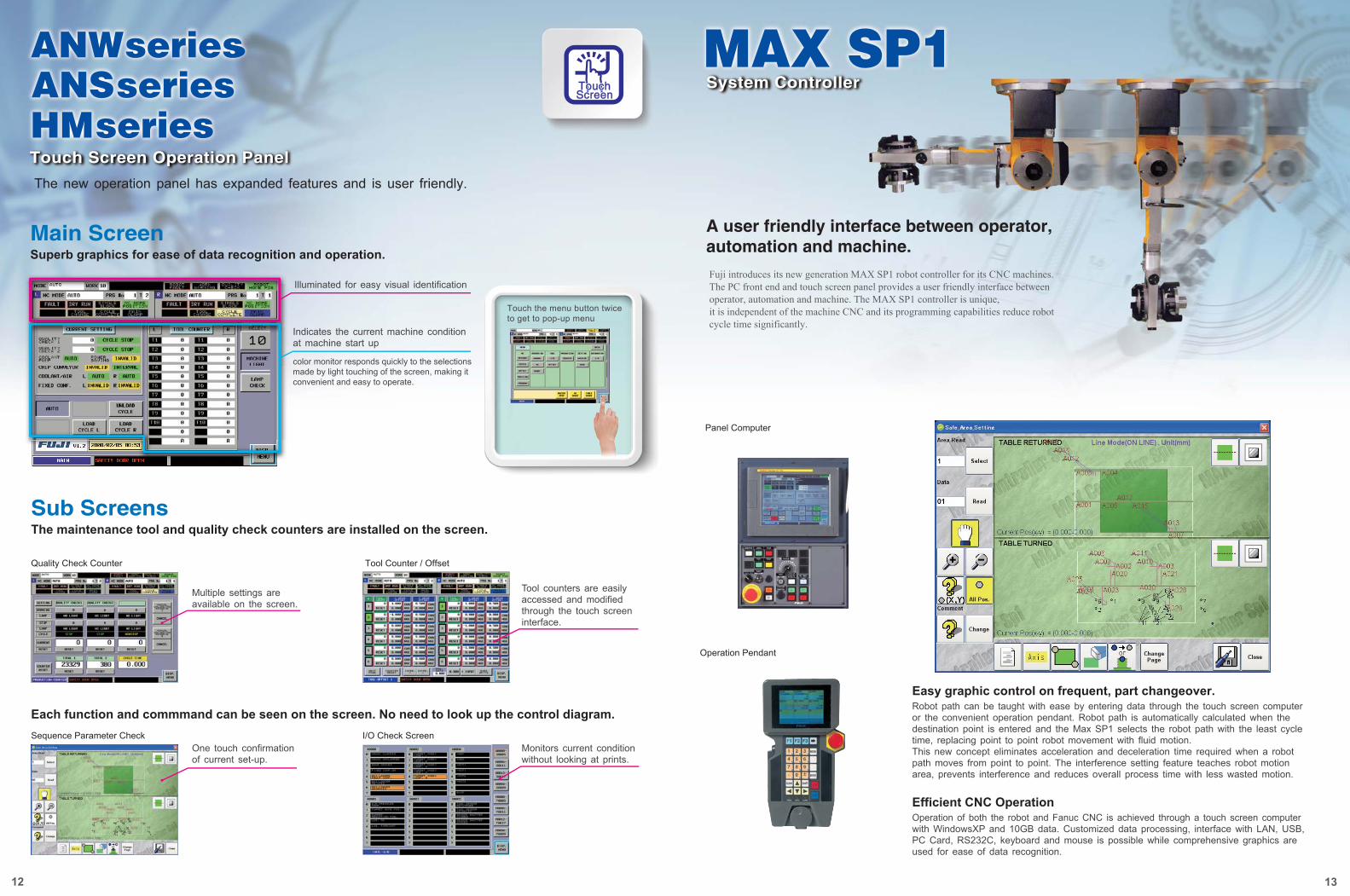
Efficient CNC Operation
A user friendly interface between operator, automation and machine.
Fuji introduces its new generation MAX SP1 robot controller for its CNC machines. The PC front end and touch screen panel provides a user friendly interface between operator, automation and machine. The MAX SP1 controller is unique, it is independent of the machine CNC and its programming capabilities reduce robot cycle time significantly.
System Controller
Tool counters are easily accessed and modified through the touch screen interface.
Multiple settings are available on the screen.
Easy graphic control on frequent, part changeover.
Operation of both the robot and Fanuc CNC is achieved through a touch screen computer with WindowsXP and 10GB data. Customized data processing, interface with LAN, USB, PC Card, RS232C, keyboard and mouse is possible while comprehensive graphics are used for ease of data recognition.
Robot path can be taught with ease by entering data through the touch screen computer or the convenient operation pendant. Robot path is automatically calculated when the destination point is entered and the Max SP1 selects the robot path with the least cycle time, replacing point to point robot movement with fluid motion.This new concept eliminates acceleration and deceleration time required when a robot path moves from point to point. The interference setting feature teaches robot motion area, prevents interference and reduces overall process time with less wasted motion.
-10.0
-5.0
0.0
5.0
10.0
(h)0 2 4 6 8
6μm
-4.0 -3.5
-2.0
1h stop
Dim
ensi
onal
cha
nge
(μm
)
-10.0
-5.0
0.0
5.0
10.0
(h)0 2 4 6 8
5μm
-2.0
3.0-1.0
1h stop
Dim
ensi
onal
cha
nge
(μm
)
-10.0
-5.0
0.0
5.0
10.0
(h)0 2 4 6 8
6.6μm0.3
-4.3
-6.31h stopD
imen
sion
al c
hang
e (μ
m)
The above-mentioned data is actual values, but not a performance guarantee.
Dimensional change after 8h running
Dimensional change after 1h stop
Dimensional change after 8h running
Dimensional change after 1h stop
Dimensional change after 8h running
Dimensional change after 1h stop
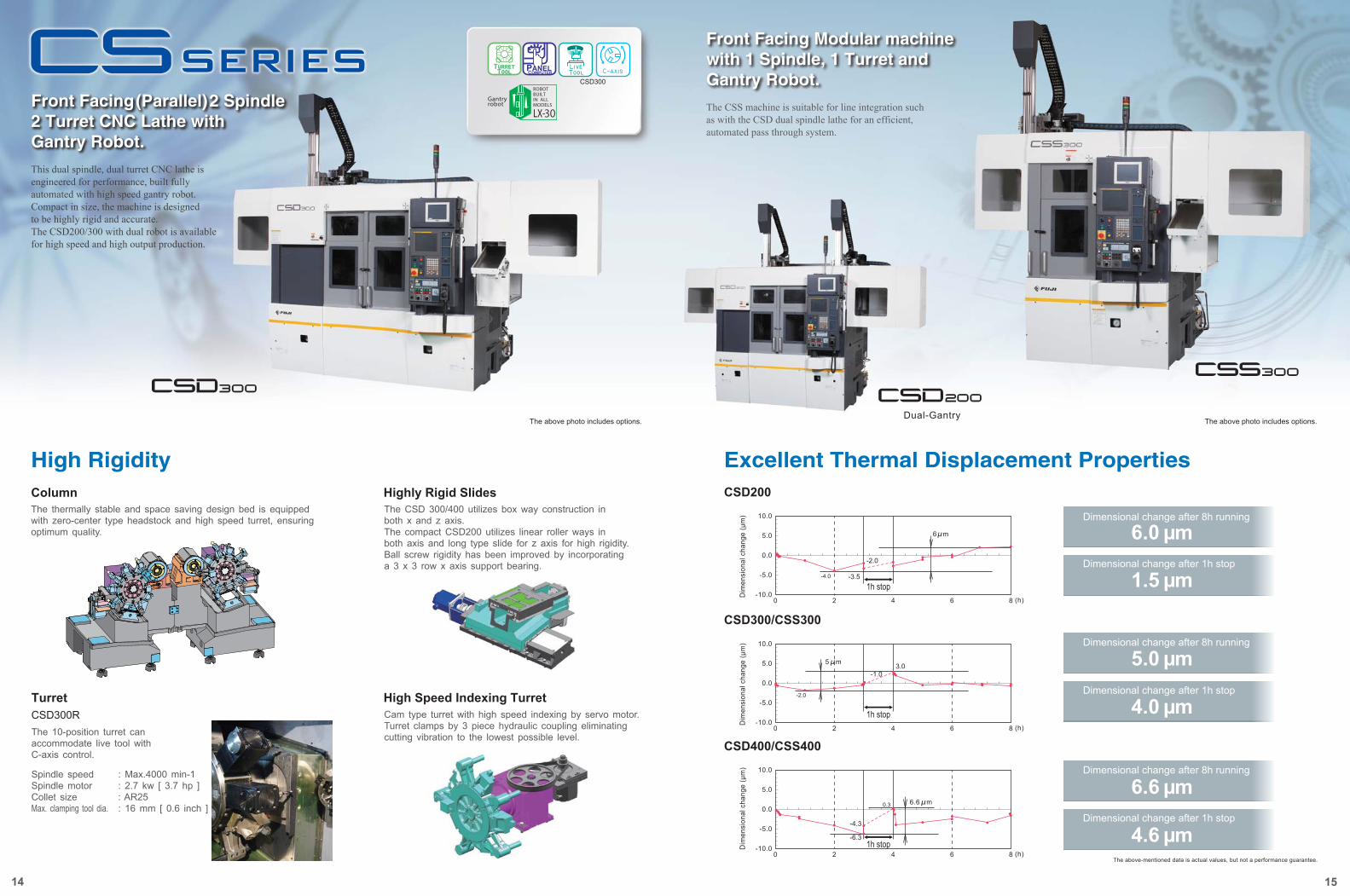
Front Facing(Parallel)2 Spindle 2 Turret CNC Lathe with Gantry Robot.
Dual-Gantry
Excellent Thermal Displacement PropertiesCSD200
CSD300/CSS300
CSD400/CSS400
The above photo includes options. The above photo includes options.
High RigidityColumn
High Speed Indexing Turret
Highly Rigid Slides
TurretCSD300R
14 15
This dual spindle, dual turret CNC lathe is engineered for performance, built fully automated with high speed gantry robot. Compact in size, the machine is designed to be highly rigid and accurate.The CSD200/300 with dual robot is available for high speed and high output production.
Front Facing Modular machine with 1 Spindle, 1 Turret and Gantry Robot.The CSS machine is suitable for line integration such as with the CSD dual spindle lathe for an efficient, automated pass through system.
The thermally stable and space saving design bed is equipped with zero-center type headstock and high speed turret, ensuring optimum quality.
The 10-position turret can accommodate live tool with C-axis control.
Spindle speedSpindle motorCollet sizeMax. clamping tool dia.
: Max.4000 min-1: 2.7 kw [ 3.7 hp ]: AR25: 16 mm [ 0.6 inch ]
The CSD 300/400 utilizes box way construction in both x and z axis.The compact CSD200 utilizes linear roller ways in both axis and long type slide for z axis for high rigidity.Ball screw rigidity has been improved by incorporating a 3 x 3 row x axis support bearing.
Cam type turret with high speed indexing by servo motor.Turret clamps by 3 piece hydraulic coupling eliminating cutting vibration to the lowest possible level.
6.0 μm
1.5 μm
5.0 μm
4.0 μm
6.6 μm
4.6 μm
CSD300
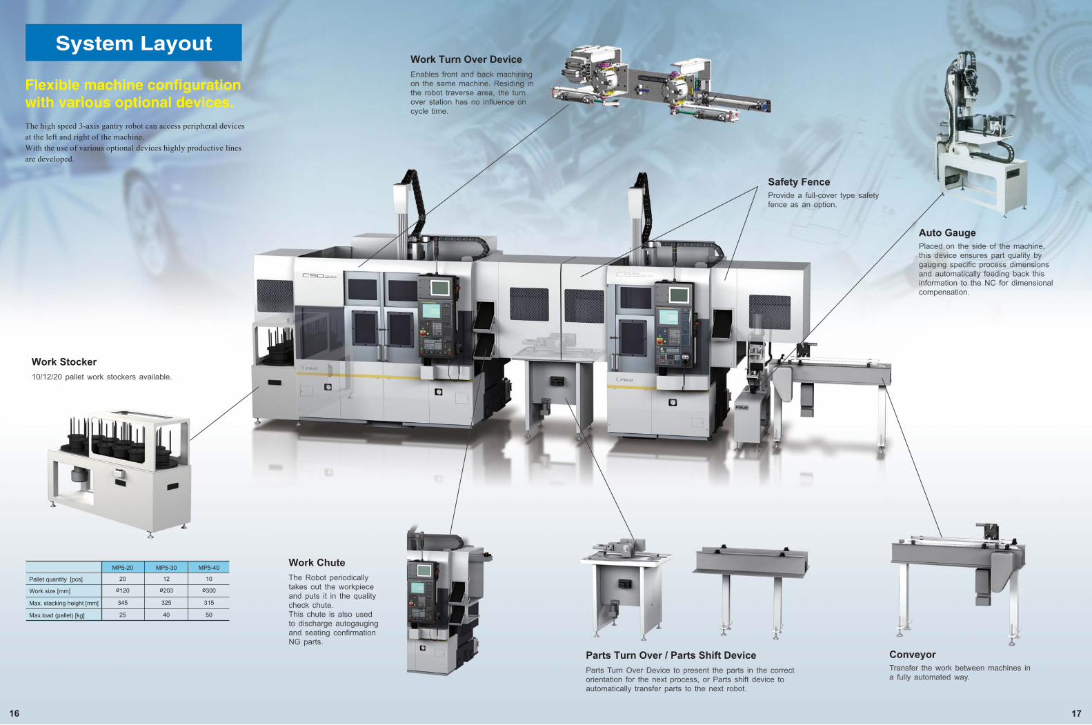
Work Turn Over Device
16 17
Safety FenceProvide a full-cover type safety fence as an option.
Auto GaugePlaced on the side of the machine, this device ensures part quality by gauging specific process dimensions and automatically feeding back this information to the NC for dimensional compensation.
ConveyorTransfer the work between machines in a fully automated way.
Enables front and back machining on the same machine. Residing in the robot traverse area, the turn over station has no influence on cycle time.
Work Stocker10/12/20 pallet work stockers available.
Work ChuteThe Robot periodically takes out the workpiece and puts it in the quality check chute.This chute is also used to discharge autogauging and seating confirmation NG parts.
Parts Turn Over / Parts Shift DeviceParts Turn Over Device to present the parts in the correct orientation for the next process, or Parts shift device to automatically transfer parts to the next robot.
Flexible machine configuration with various optional devices.The high speed 3-axis gantry robot can access peripheral devices at the left and right of the machine.With the use of various optional devices highly productive lines are developed.
20Pallet quantity [pcs]
ø120Work size [mm]
345Max. stacking height [mm]
25Max.load (pallet) [kg]
MP5-20
12
ø203
325
40
MP5-30
10
ø300
315
50
MP5-40
System Layout
B
A
Size.unit : m2 [ f t2 ]
18 19
Swivel Head Robot Chuck
Specification for CS series
Tool detector Work Pusher
CS series Line up
Machine Specifications
Specifications are subject to change without notice.※1 for North America / Europe ※2 CSD300R
Robot Specifications
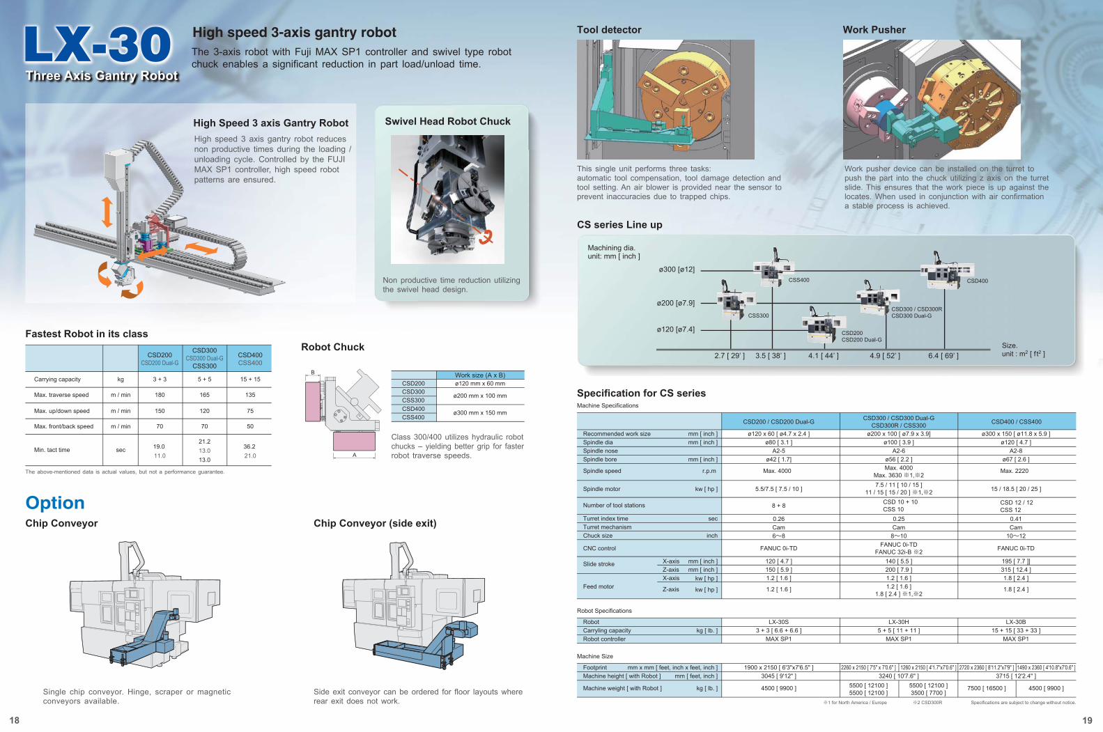
Three Axis Gantry Robot
High speed 3-axis gantry robot
2.7 [ 29’ ] 3.5 [ 38’ ] 4.1 [ 44’ ] 4.9 [ 52’ ] 6.4 [ 69’ ]
Recommended work sizeSpindle diaSpindle noseSpindle bore
Spindle speed
Spindle motor
Number of tool stations
Turret index timeTurret mechanism Chuck size
CNC control
Slide stroke
Feed motor
mm [ inch ]mm [ inch ]
mm [ inch ]
r.p.m
kw [ hp ]
sec
inch
mm [ inch ]mm [ inch ]
kw [ hp ]
kw [ hp ]
X-axisZ-axisX-axis
Z-axis
ø120 x 60 [ ø4.7 x 2.4 ]ø80 [ 3.1 ]
A2-5ø42 [ 1.7]
Max. 4000
5.5/7.5 [ 7.5 / 10 ]
8 + 8
0.26Cam6~8
FANUC 0i-TD
120 [ 4.7 ]150 [ 5.9 ]1.2 [ 1.6 ]
1.2 [ 1.6 ]
ø300 x 150 [ ø11.8 x 5.9 ]ø120 [ 4.7 ]
A2-8ø67 [ 2.6 ]
Max. 2220
15 / 18.5 [ 20 / 25 ]
CSD 12 / 12CSS 12
0.41Cam
10~12
FANUC 0i-TD
195 [ 7.7 ]]315 [ 12.4 ]1.8 [ 2.4 ]
1.8 [ 2.4 ]
ø200 x 100 [ ø7.9 x 3.9]ø100 [ 3.9 ]
A2-6ø56 [ 2.2 ]Max. 4000
Max. 3630 ※1,※2
RobotCarryling capacityRobot controller
kg [ lb. ]LX-30S
3 + 3 [ 6.6 + 6.6 ]MAX SP1
LX-30B15 + 15 [ 33 + 33 ]
MAX SP1
LX-30H5 + 5 [ 11 + 11 ]
MAX SP1
Machine Size
FootprintMachine height [ with Robot ]
Machine weight [ with Robot ]
mm [ feet, inch ]
kg [ lb. ]
mm x mm [ feet, inch x feet, inch ] 1900 x 2150 [ 6'3"x7'6.5" ]3045 [ 9'12" ]
4500 [ 9900 ]
2720 x 2360 [ 8'11.2"x7'9" ] 1490 x 2360 [ 4'10.8"x7'0.6" ]3715 [ 12'2.4" ]
7500 [ 16500 ] 4500 [ 9900 ]
2260 x 2150 [ 7'5" x 7'0.6" ] 1260 x 2150 [ 4'1.7"x7'0.6" ]3240 [ 10'7.6" ]
5500 [ 12100 ]5500 [ 12100 ]
5500 [ 12100 ]3500 [ 7700 ]
7.5 / 11 [ 10 / 15 ]11 / 15 [ 15 / 20 ] ※1,※2
CSD 10 + 10CSS 10
0.25Cam
8~10FANUC 0i-TD
FANUC 32i-B ※2140 [ 5.5 ]200 [ 7.9 ]1.2 [ 1.6 ]1.2 [ 1.6 ]
1.8 [ 2.4 ] ※1,※2
CSD200 / CSD200 Dual-G CSD300 / CSD300 Dual-GCSD300R / CSS300 CSD400 / CSS400
CSS400
CSS300
CSD200CSD200 Dual-G
CSD300 / CSD300RCSD300 Dual-G
CSD400
Machining dia.unit: mm [ inch ]
ø300 [ø12]
ø200 [ø7.9]
ø120 [ø7.4]
Option
Fastest Robot in its class
High Speed 3 axis Gantry Robot
Robot Chuck
Chip Conveyor Chip Conveyor (side exit)
High speed 3 axis gantry robot reduces non productive times during the loading / unloading cycle. Controlled by the FUJI MAX SP1 controller, high speed robot patterns are ensured.
Non productive time reduction utilizing the swivel head design.
Class 300/400 utilizes hydraulic robot chucks – yielding better grip for faster robot traverse speeds.
Carrying capacity kg
CSD200CSD200 Dual-G
3 + 3
CSD300CSD300 Dual-G
CSS300
5 + 5
CSD400CSS400
15 + 15
Max. traverse speed m / min 180 165 135
Max. up/down speed m / min 150 120 75
Max. front/back speed m / min 70 70 50
Min. tact time sec 19.0 11.0
21.213.013.0
36.2 21.0
The above-mentioned data is actual values, but not a performance guarantee.
Single chip conveyor. Hinge, scraper or magnetic conveyors available.
Side exit conveyor can be ordered for floor layouts where rear exit does not work.
CSD300CSS300CSD400CSS400
ø200 mm x 100 mm
ø300 mm x 150 mm
ø120 mm x 60 mmWork size (A x B)
CSD200
This single unit performs three tasks:automatic tool compensation, tool damage detection and tool setting. An air blower is provided near the sensor to prevent inaccuracies due to trapped chips.
Work pusher device can be installed on the turret to push the part into the chuck utilizing z axis on the turret slide. This ensures that the work piece is up against the locates. When used in conjunction with air confirmation a stable process is achieved.
The 3-axis robot with Fuji MAX SP1 controller and swivel type robot chuck enables a significant reduction in part load/unload time.
90900 mmmm900 mm
700 mm
Base Module
Machine Module45450 mmmm450 mm
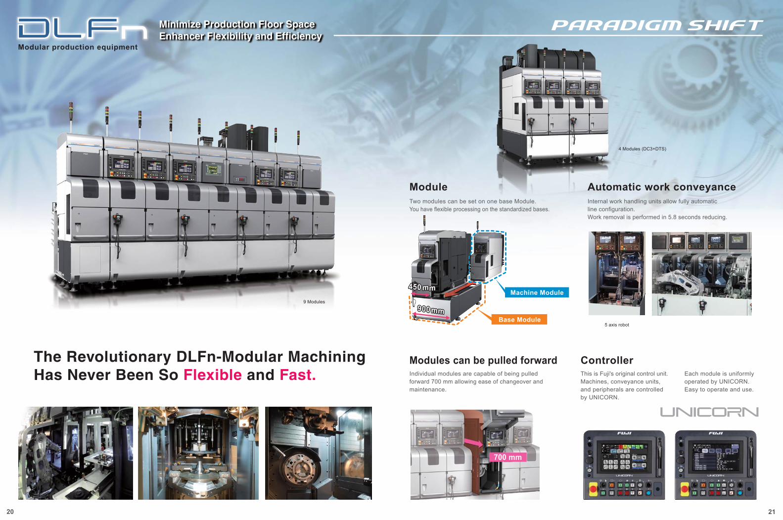
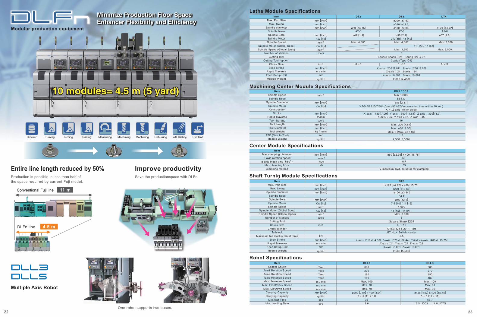
Modular production equipment
Minimize Production Floor SpaceEnhancer Flexibility and Efficiency
20 21
The Revolutionary DLFn-Modular MachiningHas Never Been So Flexible and Fast.
ControllerThis is Fuji's original control unit. Machines, conveyance units,and peripherals are controlled by UNICORN.
Each module is uniformly operated by UNICORN.Easy to operate and use.
Modules can be pulled forward
Two modules can be set on one base Module. You have flexible processing on the standardized bases.
Internal work handling units allow fully automatic line configuration. Work removal is performed in 5.8 seconds reducing.
Automatic work conveyanceModule
5 axis robot
Individual modules are capable of being pulled forward 700 mm allowing ease of changeover and maintenance.
4 Modules (DC3+DTS)
9 Modules
Multiple Axis Robot
One robot supports two bases.
11 m
4.5 m
Modular production equipment
10 modules= 4.5 m (5 yard)10 modules= 4.5 m (5 yard)
Stocker Measuring Machining Deburring Parts Washing Exit UnitMachiningTurning Turning Turning
Production is possible in less than half of the space required by current Fuji model.
Entire line length reduced by 50%Save the productionspace with DLFn
Improve productivity
DLFn line
Conventional Fuji line
22
Minimize Production Floor SpaceEnhancer Flexibility and Efficiency
Lathe Module Specifications
Machining Center Module Specifications
DT4DT2 DT3Item
ø310 [ø12.2]ø120 [ø4.72]
A2-8ø67 [2.6]
ø100 [ø3.94]A2-6
ø56 [2.2]
ø80 [ø3.15]A2-5
ø47 [1.9]7.5 [10] / 11 [15]
Max. 3,000
Max. 3,0008
Square Shank □25 Boring Bar φ32Capto (Type-C4)
8~12X-axis : 200 [7.87] Z-axis : 230 [9.06]
X-axis : 24 Z-axis : 24X-axis : 0.001 Z-axis : 0.001
2,000 [4,400]
mm [inch]mm [inch]
mm [inch]KW [hp]
min-1
KW [hp]min-1
tools
inchmm [inch]
kg [lb.]
m / minmm
Max. Swingmm [inch]Max. Part Size ø200 [ø7.87]
Spindle diameterSpindle NoseSpindle BoreSpindle MotorSpindle Speed
Spindle Motor (Global Spec)Spindle Speed (Global Spec)
Number of stationsCutting Tool
Cutting Tool (option)Chuck SizeSlide Stroke
Rapid TraverseFeed Setup UnitModule Weight
Max. 4,000
Max. 3,600
Max. 4,300
8~106~8
11 [15] / 15 [20]
DM3 / DC3ItemMax.10000
BBT30ø55 [2.17]
3.7/5.5/22 [5/7/30] (Cont./50%ED/acceleration time within 10 sec)X, Y, Z-axis roller guide
X-axis : 180 [7.09] Y-axis : 300 [11.81] Z-axis : 330[13.0]X-axis : 25 Y-axis : 45 Z-axis : 45
16Max. 200 [7.87]Max. ø60 [2.36]
Max. 3 [Max. 32 / 16]1.3
2,500 [5,500]
min-1
mm [inch]KW [hp]
mm [inch]m/mintools
mm [inch]mm [inch]kg / tools
seckg [lb.]
Spindle SpeedSpindle Nose
Spindle DiameterSpindle MotorConstruction
StrokeRapid Traverse
Tool StorageTool Length
Tool DiameterTool Weight
ATC (Tool to Tool)Module Weight
ø60 [ø2.36] x 400 [15.75]50 0.7
mm [inch]min-1
seckN
Center Module SpecificationsItem
332-indivisual hyd. actuator for clamping
Max.clamping diameterB axis rotation speed
B axis index time (180°)
Max.clamping forceClamping method
Shaft Turnig Module Specifications
Robot Specifications
Item
C1SB 125 x 20 1 PortMT No.4 Built-in center
X-axis : 110st [4.33] Z-axis : 570st [22.44] Tailstock-axis : 400st [15.75]X-axis : 24 Y-axis : 24 Z-axis : 24
X-axis : 0.001 Z-axis : 0.001
inch
Max. SwingMax. Part Size
Spindle diameterSpindle NoseSpindle BoreSpindle MotorSpindle Speed
Number of stationsCutting ToolChuck Size
Chuck cylinderTailstock
Maximum tail stock's thrust forceSlide Stroke
Rapid TraverseFeed Setup UnitModule Weight
DTS
ø270 [ø10.63]ø100 [ø3.94]
A2-6ø56 [ø2.2]
7.5 [10] / 11 [15]
8 ~ 10
8
2,500 [5,500]
mm [inch]mm [inch]
mm [inch]KW [hp]
min-1
tools
kNmm [inch]
kg [ib.]
m / minmm
mm [inch]
4,000Spindle Motor (Global Spec)Spindle Speed (Global Spec)
11 [15] / 15 [20] KW [hp]min-1 Max. 3,600
Square Shank □25
5.5
ø125 [ø4.92] x 400 [15.75]
Item
9.6secsec
Loader ChuckArm1 Rotation SpeedArm2 Rotation SpeedTable Rotation SpeedMax. Traverse Speed
Max. Front/Back Speed
Carrying CapacityMin.Tact Time
Min. Loading Time
DLL3
270180180
Max. 100
36
°/sec°/sec°/sec
m / minm / min
kg [lb.]
°/sec
Max. 70Max. Up/Down Speed
Carrying CapacityMax. 70m / min
mm [inch] ø200 [7.87] x 100 [3.94]5 + 5 [11 + 11]
600
16.5 / DC3 14.8 / DTS
DLLS
270150180
Max. 100
53.7
Max. 51Max. 39
ø125 [4.92] x 400 [15.75]5 + 5 [11 + 11]
360
23
10 modules= 4.5 m (5 yard)
24 25
High speed indexing turret
High rigidity slide
The abore-mentioned data is actual values but not a performance guarantee.
Tailstock
TurretTN400RThe 12-position turret can accommodate live tool with C-axis control.
Shaft works are available with tailstock.
Spindle speedSpindle motorCollet sizeMax. clamping tool dia.
: Max.4000 min-1: 4.5 kw [ 6.0 hp ]: AR32: 20 mm [ 0.8 inch ]
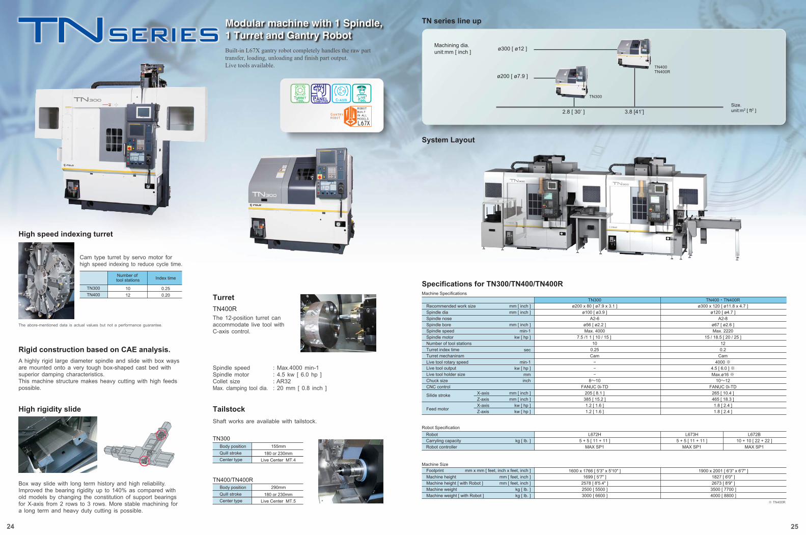
Modular machine with 1 Spindle, 1 Turret and Gantry RobotBuilt-in L67X gantry robot completely handles the raw part transfer, loading, unloading and finish part output.Live tools available.
10TN300 0.2512TN400 0.20
Number of tool stations Index time
TN400/TN400R
TN300155mmBody position
180 or 230mmQuill strokeLive Center MT.4Center type
290mmBody position180 or 230mmQuill stroke
Live Center MT.5Center type
Rigid construction based on CAE analysis.A highly rigid large diameter spindle and slide with box ways are mounted onto a very tough box-shaped cast bed with superior damping characteristics. This machine structure makes heavy cutting with high feeds possible.
Cam type turret by servo motor for high speed indexing to reduce cycle time.
Box way slide with long term history and high reliability. Improved the bearing rigidity up to 140% as compared with old models by changing the constitution of support bearings for X-axis from 2 rows to 3 rows. More stable machining for a long term and heavy duty cutting is possible.
TN series line up
System Layout
2.8 [ 30’ ]
TN300
TN400TN400R
3.8 [41’]
ø300 [ ø12 ]
ø200 [ ø7.9 ]
Machine Specifications
Recommended work sizeSpindle diaSpindle noseSpindle boreSpindle speedSpindle motorNumber of tool stationsTurret index timeTurret mechaninsmLive tool rotary speed
RobotCarryling capacityRobot controller
kg [ lb. ]L672H
5 + 5 [ 11 + 11 ]MAX SP1
L673H5 + 5 [ 11 + 11 ]
MAX SP1
L672B10 + 10 [ 22 + 22 ]
MAX SP1
Silide stroke
Feed motor
mm [ inch ]mm [ inch ]
mm [ inch ]min-1
kw [ hp ]
sec
min-1Live tool outputLive tool holder sizeChuck sizeCNC control
mmkw [ hp ]
inch
mm [ inch ]mm [ inch ]
kw [ hp ]kw [ hp ]
X-axisZ-axisX-axisZ-axis
ø200 x 80 [ ø7.9 x 3.1 ]ø100 [ ø3.9 ]
A2-6ø56 [ ø2.2 ]Max. 4000
7.5 /1 1 [ 10 / 15 ] 10
0.25Cam
−−−
8~10
4000 ※4.5 [ 6.0 ] ※Max.ø16 ※
10~12FANUC 0i-TD FANUC 0i-TD
205 [ 8.1 ]385 [ 15.2 ]1.2 [ 1.6 ]1.2 [ 1.6 ]
ø300 x 120 [ ø11.8 x 4.7 ]ø120 [ ø4.7 ]
A2-8ø67 [ ø2.6 ]Max. 2220
15 / 18.5 [ 20 / 25 ]120.2
Cam
265 [ 10.4 ]465 [ 18.3 ]1.8 [ 2.4 ]1.8 [ 2.4 ]
TN300
Machine heightFootprint
Machine height [ with Robot ]Machine weightMachine weight [ with Robot ]
mm [ feet, inch ]mm x mm [ feet, inch x feet, inch ]
kg [ lb. ]mm [ feet, inch ]
kg [ lb. ]
1699 [ 5'7" ]2578 [ 8'5.4" ]2500 [ 5500 ]3000 [ 6600 ]
1600 x 1766 [ 5'3" x 5'10" ]1827 [ 6'0" ]2673 [ 8'9" ]
3500 [ 7700 ]4000 [ 8800 ]
1900 x 2001 [ 6'3" x 6'7" ]
TN400・TN400R
Machine Size
Specifications for TN300/TN400/TN400R
Robot Specification
Machining dia.unit:mm [ inch ]
Size.unit:m2 [ ft2 ]
※ TN400R
26 27
Specifications are subject to change without notice.※ TN400R
High Output CNC Lathe
Geared for high volume production of small to medium-sized rings with the fastest automation in its class.This compact machine is designed in pursuit of high productivity and ease of operation. High speed , high output machining and extra smooth chip disposal are based on FUJI's field-proven technologies.
O.D. Cup type
I.D. Pin type
Air chuck
L35-08H LoaderHigh speed CNC loader unloads and loads the work piece in just 2.5 sec.
Loader chuck
3-jaw type loading chuck available for quick change-over
Work example
Machine
Work pieceCycletime
: FS4-31: FS4-3100: inner ring: 13 sec
Machine
Work pieceCycletime
: FS4-31: FS4-3100: inner race: 20.8 sec
Machine SpecificationsSpecifications for FS4-31/FS4-3100
Robot Specifications
Machine Size
Specifications are subject to change without notice.
The above photo include options.
ø100 x 60 [ ø3.9 x 2.4 ]
Gang
Recommended work sizemm [ inch ]mm [ inch ]
mm [ inch ]min-1
kw [ hp ]
ø100 [ ø3.9 ]Spindle diaA2-6Spindle nose
ø56 [ ø2.2 ]Spindle boreSpindle speed Max. 4000
7.5 / 11 [ 10 / 15 ]
8FANUC 0i-TD300 [ 11.81 ]270 [ 10.63 ]
1.6 [ 2.1 ]1.6 [ 2.1 ]
Spindle motorTooling
inch
mm [ inch ]mm [ inch ]
kw [ hp ]
Chuck sizeCNC control
1100 x 1675 [ 3'7'' x 5'6'' ]2115 [ 6’11'' ]2500 [ 5500 ]
Footprintmm [ feet, inch ]
kg [ lb. ]
mm x mm [ feet, inch x feet, inch ]Machine heightMachine weight
Slide stroke
Feed motor
X-axis
X-axisZ-axis
kw [ hp ]Z-axis
L35-08HFANUC
Cup / Pin / Air chuck2 + 2 [ 4.4 + 4.4]
1 + 1 [ 2.2 + 2.2 ]0.5 + 0.5 [ 1.1 + 1.1 ]
Robot
kg [ lb. ]kg [ lb. ]kg [ lb. ]
Robot controllerLoader chuck
Carrying capacityCup / Pin
Air chuck (rotatory)Air chuck (fixed)
FS4-31 / 3100
165mmA
6.5inch
FS4-31FS4-3100
60.15[2.37”]
75.60[2.97”]
22.455[0.88”]
27.20[1.07”]
A
1
2
3
1
23
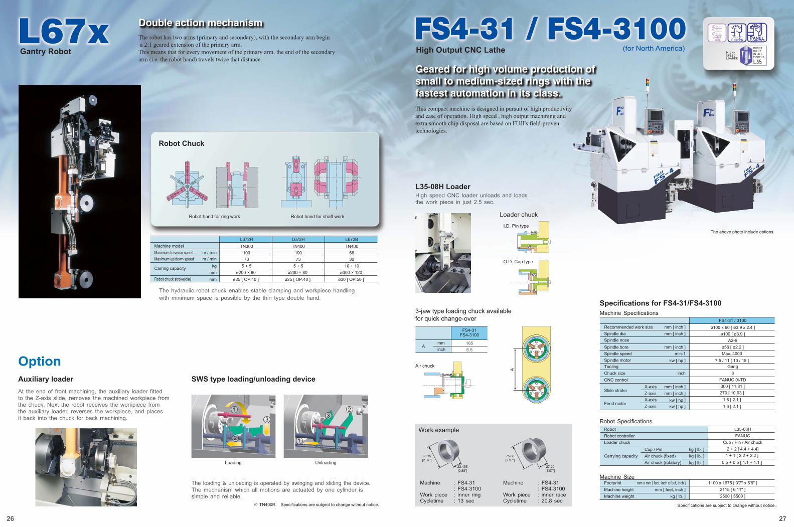
Gantry Robot
Double action mechanismThe robot has two arms (primary and secondary), with the secondary arm begin a 2:1 geared extension of the primary arm. This means that for every movement of the primary arm, the end of the secondary arm (i.e. the robot hand) travels twice that distance.
Robot Chuck
Loading Unloading
Robot hand for ring work Robot hand for shaft work
The hydraulic robot chuck enables stable clamping and workpiece handling with minimum space is possible by the thin type double hand.
Machine modelm / minm / min
kgmmmm
TN300Maximum traverse speed 100Maximum up/down speed 73
Carring capacity 5 + 5ø200 × 80
Robot chuck stroke(dia) ø25 [ OP:40 ]
L672HTN400
10073
5 + 5ø200 × 80
ø25 [ OP:40 ]
L673HTN400
6630
10 + 10ø300 × 120
ø30 [ OP:50 ]
L672B
OptionAuxiliary loader SWS type loading/unloading deviceAt the end of front machining, the auxiliary loader fitted to the Z-axis slide, removes the machined workpiece from the chuck. Next the robot receives the workpiece from the auxiliary loader, reverses the workpiece, and places it back into the chuck for back machining.
The loading & unloading is operated by swinging and sliding the device. The mechanism which all motions are actuated by one cylinder is simple and reliable.
(for North America)
Y-axis
Z-axis
X-axis
C-axis
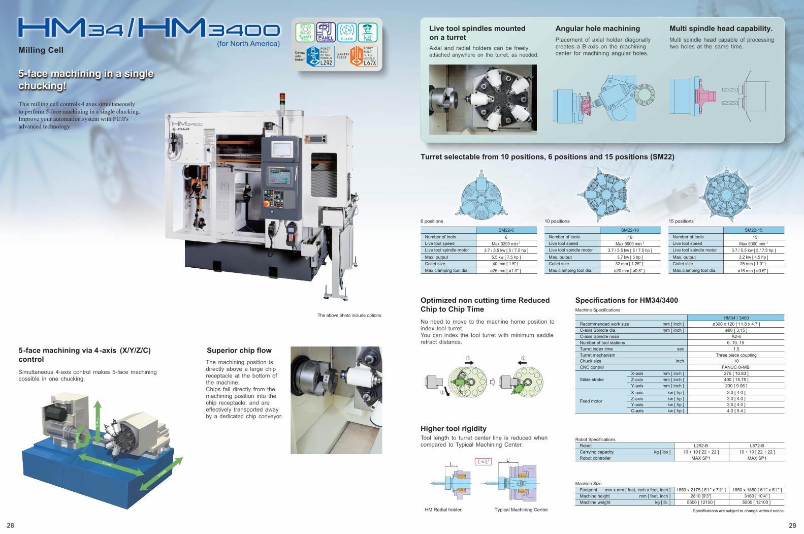
Superior chip flow5-face machining via 4 -axis (X/Y/Z/C) controlSimultaneous 4-axis control makes 5-face machining possible in one chucking.
The machining position is directly above a large chip receptacle at the bottom of the machine. Chips fall directly from the machining position into the chip receptacle, and are effectively transported away by a dedicated chip conveyor.
Turret selectable from 10 positions, 6 positions and 15 positions (SM22)
Specifications for HM34/3400
Robot Specifications
Specifications are subject to change without notice.
6 positions 10 positions 15 positions
Live tool spindles mounted on a turretAxial and radial holders can be freely attached anywhere on the turret, as needed.
Placement of axial holder diagonally creates a B-axis on the machining center for machining angular holes.
Multi spindle head capable of processing two holes at the same time.
Angular hole machining
Optimized non cutting time Reduced Chip to Chip TimeNo need to move to the machine home position to index tool turret.You can index the tool turret with minimum saddle retract distance.
Higher tool rigidityTool length to turret center line is reduced when compared to Typical Machining Center.
Multi spindle head capability.
5-face machining in a single chucking!
(for North America)
L < L’
Typical Machining Center
L’
HM Radial holder
L
6Number of toolsMax.3200 min-1Live tool speed
3.7 / 5.5 kw [ 5 / 7.5 hp ]Live tool spindle motor5.5 kw [ 7.5 hp ]Max. output
Collet size 40 mm [ 1.5" ]ø25 mm [ ø1.0" ]Max.clamping tool dia.
SM22-610Number of tools
Max.5000 min-1Live tool speed3.7 / 5.5 kw [ 5 / 7.5 hp ]Live tool spindle motor
3.7 kw [ 5 hp ]Max. outputCollet size 32 mm [ 1.25" ]
ø20 mm [ ø0.8" ]Max.clamping tool dia.
SM22-1015Number of tools
Max.5000 min-1Live tool speed3.7 / 5.5 kw [ 5 / 7.5 hp ]Live tool spindle motor
3.2 kw [ 4.5 hp ]Max. outputCollet size 25 mm [ 1.0" ]
ø16 mm [ ø0.6" ]Max.clamping tool dia.
SM22-15
Milling Cell
The above photo include options.
This milling cell controls 4 axes simultaneously to perform 5-face machining in a single chucking. Improve your automation system with FUJI's advanced technology.
28 29
Machine Specifications
Recommended work sizeC-axis Spindle dia.C-axis Spindle noseNumber of tool stationsTurret index timeTurret mechanism
Silide stroke
Feed motor
mm [ inch ]mm [ inch ]
sec
Chuck sizeCNC control
inch
mm [ inch ]mm [ inch ]
kw [ hp ]kw [ hp ]
X-axisZ-axis
X-axisZ-axis
ø300 x 120 [ 11.8 x 4.7 ]ø80 [ 3.15 ]
A2-66, 10, 15
1.5Three piece coupling
10FANUC 0i-MB 275 [ 10.83 ]400 [ 15.75 ]
mm [ inch ]Y-axis 230 [ 9.06 ]3.0 [ 4.0 ]3.0 [ 4.0 ]
kw [ hp ]kw [ hp ]
Y-axisC-axis
3.0 [ 4.0 ]4.0 [ 5.4 ]
HM34 / 3400
RobotCarrying capacityRobot controller
kg [ lbs ]L292-B
10 + 10 [ 22 + 22 ]MAX SP1
L672-B10 + 10 [ 22 + 22 ]
MAX SP1
Machine SizeFootprintMachine heightMachine weight
mm [ feet, inch ]kg [ lb. ]
mm x mm [ feet, inch x feet, inch ]2810 [9'3"]
5500 [ 12100 ]
1850 x 1850 [ 6'1" x 6'1" ]3160 [ 10'4" ]
5500 [ 12100 ]
1850 x 2175 [ 6'1" x 7'2" ]
30 31
High Rigidity
FUJI's Basic and Special Technologies
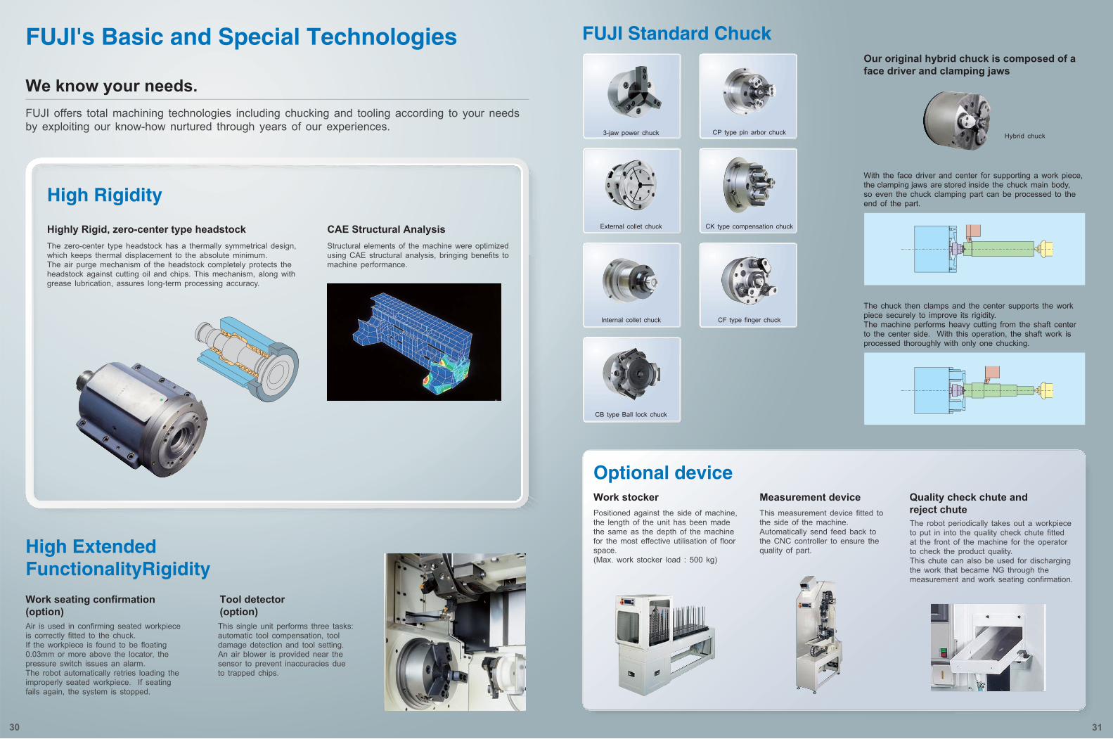
We know your needs. FUJI offers total machining technologies including chucking and tooling according to your needs by exploiting our know-how nurtured through years of our experiences.
3-jaw power chuck
External collet chuck
Internal collet chuck
CB type Ball lock chuck
Highly Rigid, zero-center type headstockThe zero-center type headstock has a thermally symmetrical design, which keeps thermal displacement to the absolute minimum. The air purge mechanism of the headstock completely protects the headstock against cutting oil and chips. This mechanism, along with grease lubrication, assures long-term processing accuracy.
Structural elements of the machine were optimized using CAE structural analysis, bringing benefits to machine performance.
Work seating confirmation (option)Air is used in confirming seated workpiece is correctly fitted to the chuck. If the workpiece is found to be floating 0.03mm or more above the locator, the pressure switch issues an alarm. The robot automatically retries loading the improperly seated workpiece. If seating fails again, the system is stopped.
This single unit performs three tasks: automatic tool compensation, tool damage detection and tool setting. An air blower is provided near the sensor to prevent inaccuracies due to trapped chips.
Measurement device Quality check chute and reject chute
Work stockerPositioned against the side of machine, the length of the unit has been made the same as the depth of the machine for the most effective utilisation of floor space. (Max. work stocker load : 500 kg)
This measurement device fitted to the side of the machine. Automatically send feed back to the CNC controller to ensure the quality of part.
The robot periodically takes out a workpiece to put in into the quality check chute fitted at the front of the machine for the operator to check the product quality. This chute can also be used for discharging the work that became NG through the measurement and work seating confirmation.
Our original hybrid chuck is composed of a face driver and clamping jaws
Tool detector (option)
CAE Structural Analysis
Optional device
FUJI Standard Chuck
High Extended FunctionalityRigidity
CP type pin arbor chuck Hybrid chuck
With the face driver and center for supporting a work piece, the clamping jaws are stored inside the chuck main body, so even the chuck clamping part can be processed to the end of the part.
The chuck then clamps and the center supports the work piece securely to improve its rigidity. The machine performs heavy cutting from the shaft center to the center side. With this operation, the shaft work is processed thoroughly with only one chucking.
CK type compensation chuck
CF type finger chuck

![Servo CAT.NO.N3312E - Sugino Corp · 2014-12-29 · CAT.NO.N3312E Adjustable spindle nose[ST3・ST4] An adjustable spindle nose is available for ST3 and ST4 models. Please specify](https://img.pdfslide.net/doc/110x75/5e940696df5b97614f4141c5/servo-catnon3312e-sugino-corp-2014-12-29-catnon3312e-adjustable-spindle.jpg)


![400 mm PALLET HORIZONTAL MACHINING …training.methodsmachine.com/_assets/machines/41d6e585-e2f5-4560-91...horizontal machining centers ... Spindle nose to pallet center mm [inch]](https://img.pdfslide.net/doc/110x75/5ab571647f8b9a6e1c8cd8d8/400-mm-pallet-horizontal-machining-machining-centers-spindle-nose-to-pallet.jpg)

![SPINDLE CONNECTION DATA TOPlus mini chuck · 2020. 9. 9. · SPINDLE CONNECTION DATA TOPlus mini chuck Size 65 Variant Pull-back Spindle nose DU AP120 AP140 AP170 Total length [mm]](https://img.pdfslide.net/doc/110x75/5ff9e8a372dda227452105fb/spindle-connection-data-toplus-mini-chuck-2020-9-9-spindle-connection-data.jpg)