Embed Size (px)
Citation preview
BIO ANALYTICAL TECHNIQUESTOPIC: ATOMIC FORCE
MICROSCOPYMade By:1.ABHIST KUMAR2.SHUBHAM DIXIT 3.NEHA SRIVASTAVA4.PALLAVINI PANDEY5.TANVI SINGH
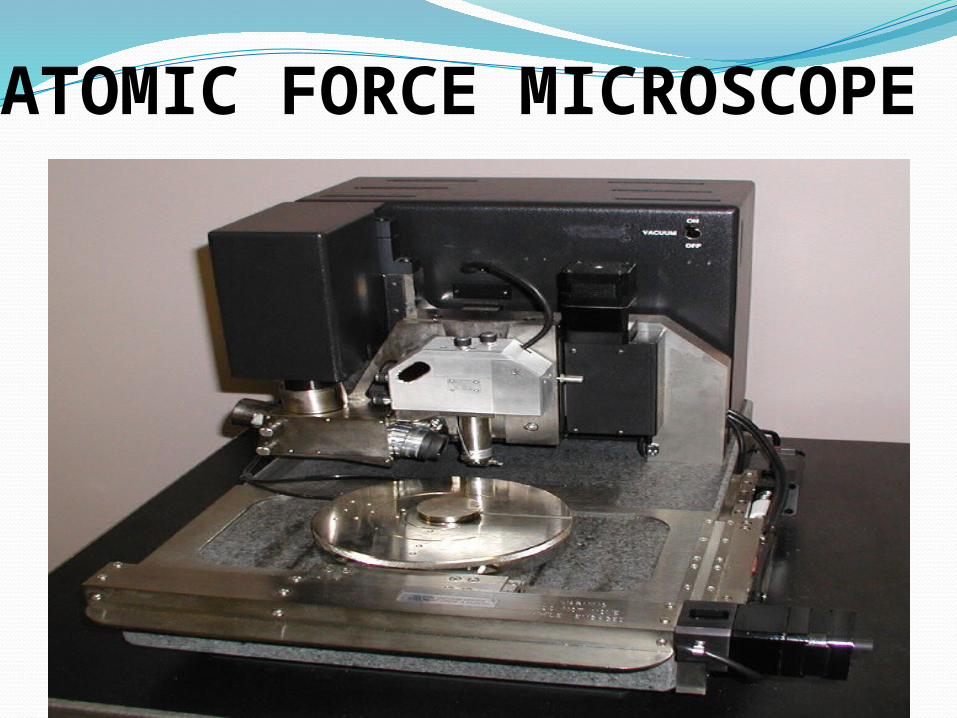
ATOMIC FORCE MICROSCOPE
INTRODUCTION
The atomic force microscope (AFM), developed in the mid 1980‘s, uses a sharp probe to magnify surface features. With the AFM, it is possible to image an object‘ s surface topography with extremely high magnifications, up to 1,000,000X. Further, the magnification of an AFM is made in three dimensions, the horizontal X-Y plane and the vertical Z dimension.
History
The first AFM was made in 1986 by Gerd Binnig, C.F Quate and Christoph Gerber by meticulously gluing a tiny shard of diamond onto one end of a tiny strip of gold foil by using cantilever to examine insulating surfaces.

Principle of AFM
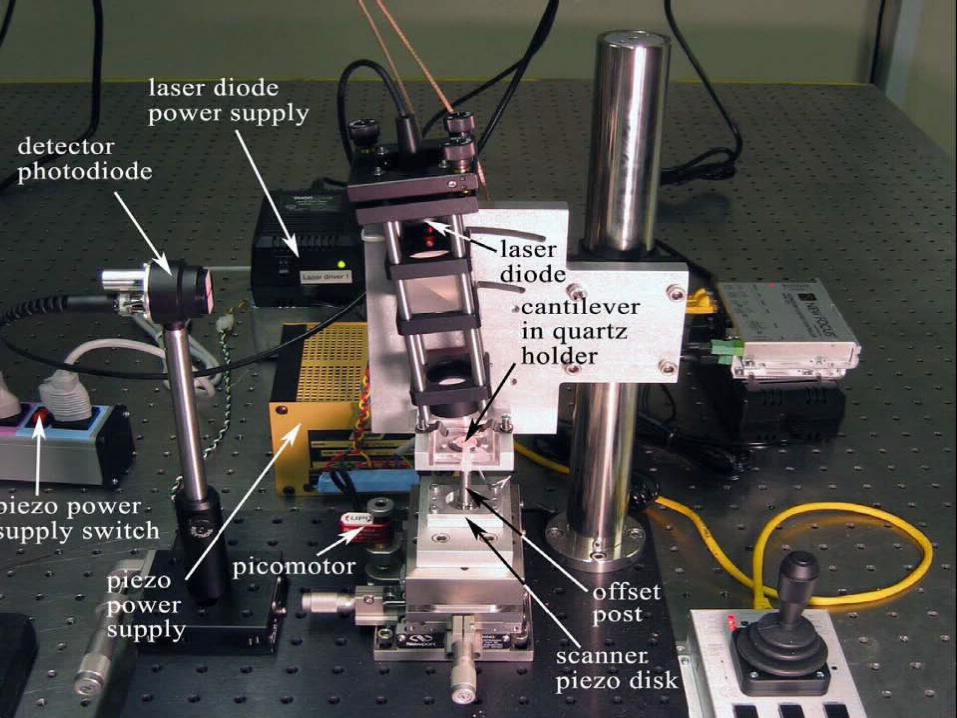
COMPONENTS OF AFM
Motion control system
Optical system
Cantilever probes for imaging
Cantilevers for thermal noise measurements
COMPONENTS OF AFM
1.) Motion control system
Manual (coarse): turning the knob on the red picomotor with your hand (clockwise moves the stage up).
Pico motor (medium): using the joystick to drive the picomotor (pushing the joystick forward moves the stage upward).
Piezo-disk (fine): actuating the piezo disk over a few hundred nanometers using the mat-lab software.
COMPONENTS OF AFM
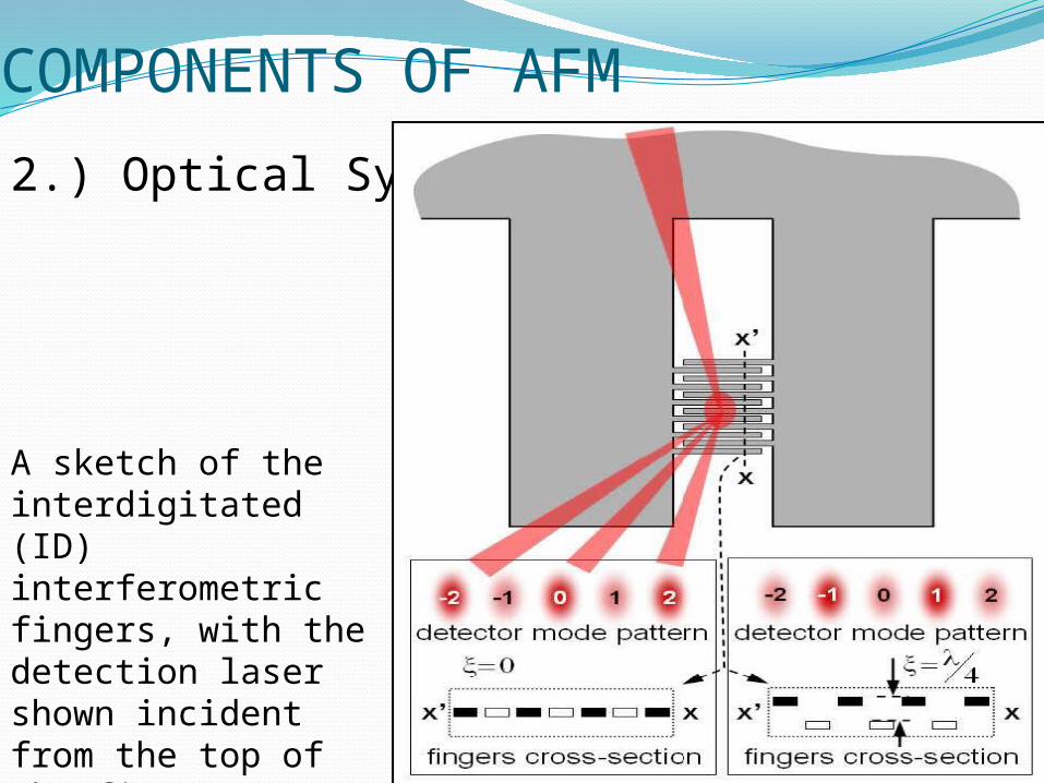
2.) Optical System
A sketch of the interdigitated (ID) interferometric fingers, with the detection laser shown incident from the top of the figure.
COMPONENTS OF AFM
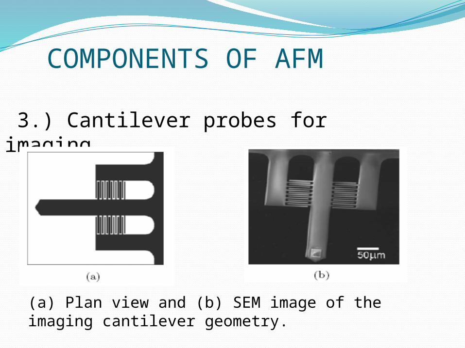
3.) Cantilever probes for imaging
(a) Plan view and (b) SEM image of the imaging cantilever geometry.
COMPONENTS OF AFM
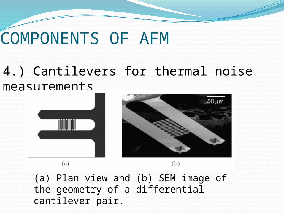
4.) Cantilevers for thermal noise measurements
(a) Plan view and (b) SEM image of the geometry of a differential cantilever pair.

IMAGING MODES
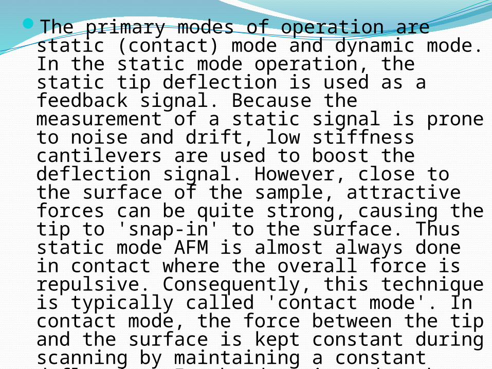
The primary modes of operation are static (contact) mode and dynamic mode. In the static mode operation, the static tip deflection is used as a feedback signal. Because the measurement of a static signal is prone to noise and drift, low stiffness cantilevers are used to boost the deflection signal. However, close to the surface of the sample, attractive forces can be quite strong, causing the tip to 'snap-in' to the surface. Thus static mode AFM is almost always done in contact where the overall force is repulsive. Consequently, this technique is typically called 'contact mode'. In contact mode, the force between the tip and the surface is kept constant during scanning by maintaining a constant deflection. In the dynamic mode, the cantilever is externally oscillated at or close to its fundamental resonance frequency or a harmonic. The oscillation amplitude, phase and resonance frequency are modified by tip-sample interaction forces; these changes in oscillation with respect to the external reference oscillation provide information about the sample's characteristics.
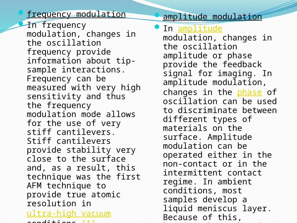
frequency modulation In frequency modulation,
changes in the oscillation frequency provide information about tip-sample interactions. Frequency can be measured with very high sensitivity and thus the frequency modulation mode allows for the use of very stiff cantilevers. Stiff cantilevers provide stability very close to the surface and, as a result, this technique was the first AFM technique to provide true atomic resolution in ultra-high vacuum conditions [1].
amplitude modulation In amplitude modulation,
changes in the oscillation amplitude or phase provide the feedback signal for imaging. In amplitude modulation, changes in the phase of oscillation can be used to discriminate between different types of materials on the surface. Amplitude modulation can be operated either in the non-contact or in the intermittent contact regime. In ambient conditions, most samples develop a liquid meniscus layer. Because of this, keeping the probe tip close enough to the sample for short-range forces to become detectable while preventing the tip from sticking.
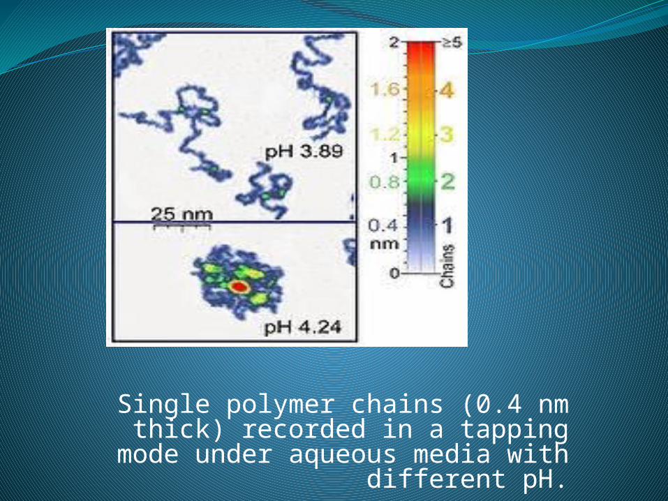
Single polymer chains (0.4 nm thick) recorded in a tapping mode
under aqueous media with different pH.

Tapping mode
In tapping mode the cantilever is driven to oscillate up and down at near its resonance frequency by a small piezoelectric element
mounted in the AFM tip holder. The amplitude of this oscillation is greater than 10 nm, typically 100 to 200 nm. Due to the
interaction of forces acting on the cantilever when the tip comes close to the surface,
Van der Waals force or dipole-dipole interaction, electrostatic forces, etc cause
the amplitude of this oscillation to decrease as the tip gets closer to the sample. An electronic servo uses the piezoelectric
actuator to control the height of the cantilever above the sample. The servo
adjusts the height to maintain a set cantilever oscillation amplitude as the
cantilever is scanned over the sample. A tapping AFM image is therefore produced by imaging the force of the oscillating contacts of the tip with the sample surface. This is an
improvement on conventional.
AFM contact mode In which the cantilever just
drags across the surface at constant force and can result in surface damage. Tapping mode is gentle enough even for the visualization of supported lipid bilayers or adsorbed single polymer molecules (for instance, 0.4 nm thick chains of synthetic polyelectrolytes) under liquid medium. At the application of proper scanning parameters, the conformation of single molecules remains unchanged for hours .
AFM non contact mode The cantilever is instead
oscillated at a frequency slightly above its resonance frequency where the amplitude of oscillation is typically a few nanometers (<10 nm). Non-contact mode AFM does not suffer from tip or sample degradation effects that are sometimes observed after taking numerous scans with contact AFM. This makes non-contact AFM preferable to contact AFM for measuring soft samples. In the case of rigid samples, contact and non-contact images may look the same. However, if a few monolayers of adsorbed fluid are lying on the surface of a rigid sample, the images may look quite different. An AFM operating in contact mode will penetrate the liquid layer to image the underlying surface, whereas in non-contact mode an AFM will oscillate above the adsorbed fluid layer to image both the liquid and surface
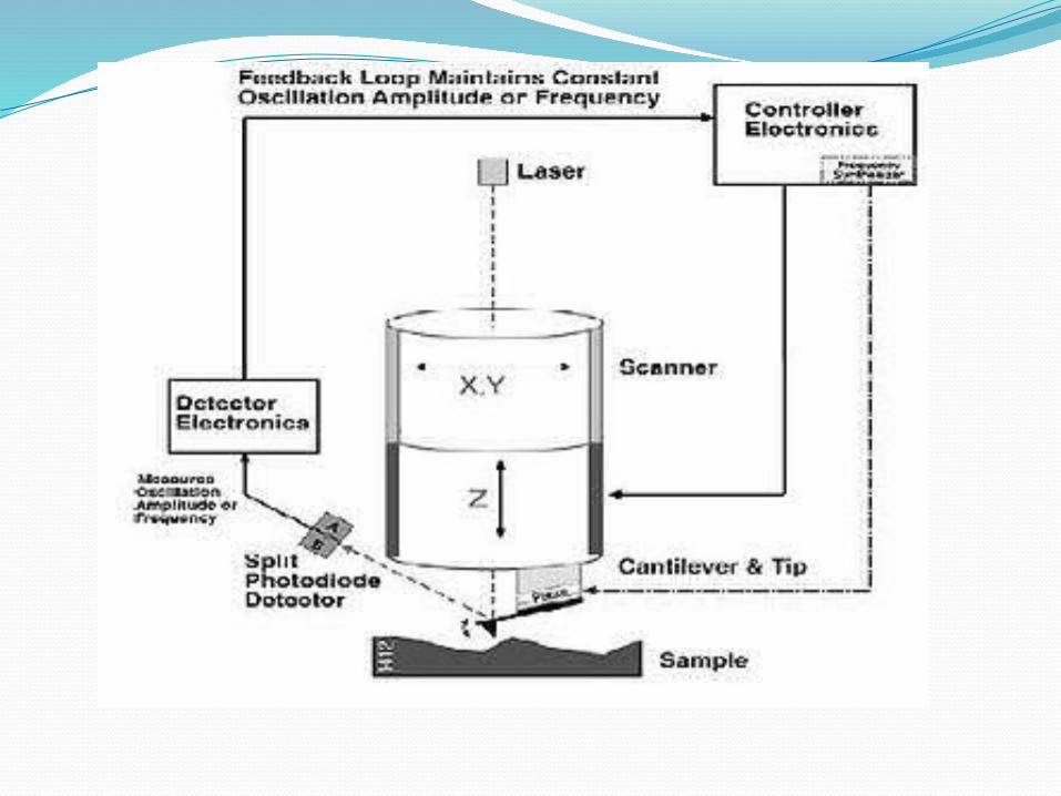
AFM cantilever deflection measurement
Laser light from a solid state diode is reflected off the back of the cantilever and collected by a position sensitive detector (PSD) consisting of two closely spaced photodiodes whose output signal is collected by a differential amplifier. Angular displacement of cantilever results in one photodiode collecting more light than the other photodiode, producing an output signal (the difference between the photodiode signals normalized by their sum) which is proportional to the deflection of the cantilever. It detects cantilever deflections <1 Å (thermal noise limited). A long beam path (several cm) amplifies changes in beam angle.
FORCE SPECTROSCOPYAnother major application of AFM (besides imaging) is force spectroscopy, the direct measurement of tip-sample interaction forces as a function of the gap between the tip and sample (the result of this measurement is called a force-distance curve). For this method, the AFM tip is extended towards and retracted from the surface as the deflection of the cantilever is monitored as a function of piezoelectric displacement. These measurements have been used to measure nanoscale contacts, atomic bonding, Van der Waals forces, and Casimir forces, dissolution forces in liquids and single molecule stretching and rupture forces [
Forces of the order of a few pico-Newton can now be routinely measured with a vertical distance resolution of better than 0.1 nanometer. Force spectroscopy can be performed with either static or dynamic modes. In dynamic modes, information about the cantilever vibration is monitored in addition to the static deflection [5]
Problems with the technique include no direct measurement of the tip-sample separation and the common need for low stiffness cantilevers which tend to 'snap' to the surface. The snap-in can be reduced by measuring in liquids or by using stiffer cantilevers, but in the latter case a more sensitive deflection sensor is needed. By applying a small dither to the tip, the stiffness (force gradient) of the bond can be measured as well
Identification of individual surface atoms
The AFM can be used to image and manipulate atoms and structures on a variety of surfaces. The atom at the apex of the tip "senses" individual atoms on the underlying surface when it forms incipient chemical bonds with each atom. Because these chemical interactions subtly alter the tip's vibration frequency, they can be detected and mapped. This principle was used to distinguish between atoms of silicon, tin and lead on an alloy surface.The trick is to first measure these forces precisely for each type of atom expected in the sample. The team found that the tip interacted most strongly with silicon atoms, and interacted 23% and 41% less strongly with tin and lead atoms, respectively. Thus, each different type of atom can be identified in the matrix as the tip is moved across the surface.
Such a technique has been used now in biology and extended recently to cell biology. Forces corresponding (i) the unbinding of receptor ligand couples (ii) unfolding of proteins (iii) cell adhesion at single cell scale have been gathered.In 2009 scientists at IBM visualised one molecule of pentacene using an AFM with a modified tip to include a CO molecule at the end, with the oxygen atom probing the surface of the pentacene molecule. This was the most detailed image of a molecule ever obtained.
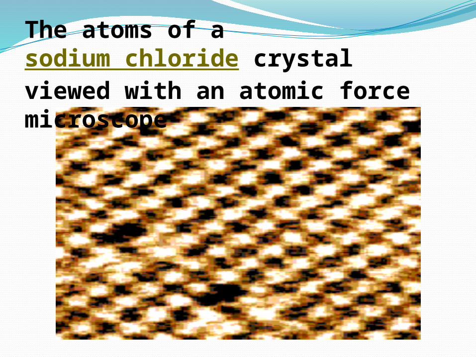
The atoms of a sodium chloride crystal viewed with an atomic force microscope
Piezoelectric scannersAFM scanners are made from piezoelectric material, which expands and contracts proportionally to an applied voltage. Whether they elongate or contract depends upon the polarity of the voltage applied. The scanner is constructed by combining independently operated piezo electrodes for X, Y, and Z into a single tube, forming a scanner which can manipulate samples and probes with extreme precision in 3 dimensions.Scanners are characterized by their sensitivity which is the ratio of piezo movement to piezo voltage, i.e., by how much the piezo material extends or contracts per applied volt. Because of differences in material or size, the sensitivity varies from scanner to scanner. Sensitivity varies non-linearly with respect to scan size..
Piezo scanners exhibit more sensitivity at the end than at the beginning of a scan. This causes the forward and reverse scans to behave differently and display hysteresis between the two scan directions. This can be corrected by applying a non-linear voltage to the piezo electrodes to cause linear scanner movement and calibrating the scanner accordingly.The sensitivity of piezoelectric materials decreases exponentially with time. This causes most of the change in sensitivity to occur in the initial stages of the scanner’s life. Piezoelectric scanners are run for approximately 48 hours before they are shipped from the factory so that they are past the point where we can expect large changes in sensitivity. As the scanner ages, the sensitivity will change less with time and the scanner would seldom require recalibration.

Advantages of AFMthe AFM provides a true three-dimensional surface profilesamples viewed by AFM do not require any special treatments (such as metal/carbon coatings) that would irreversibly change or damage the sample.AFM can provide higher resolution than SEMgive true atomic resolution in ultra-high vacuum (UHV) and, more recently, in liquid environments
Disadvantages of AFMThe AFM can only image a maximum height on the order of micrometres and a maximum scanning area of around 150 by 150 micrometres.An incorrect choice of tip for the required resolution can lead to image artifactsRequires several minutes for a typical scanAFM images can also be affected by hysteresis of the piezoelectric materialDue to the nature of AFM probes, they cannot normally measure steep walls or overhangs
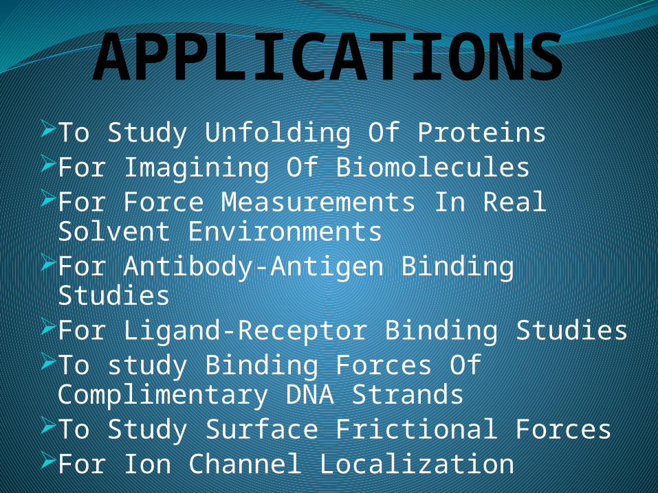
APPLICATIONSTo Study Unfolding Of ProteinsFor Imagining Of BiomoleculesFor Force Measurements In Real
Solvent EnvironmentsFor Antibody-Antigen Binding StudiesFor Ligand-Receptor Binding StudiesTo study Binding Forces Of
Complimentary DNA StrandsTo Study Surface Frictional ForcesFor Ion Channel Localization