Embed Size (px)
DESCRIPTION
Lutron Technical Support Center 1-800-523-9466 24 hrs / 7 days www.lutron.com For Incandescent/Halogen Lighting, use an Incandescent/Halogen Dimmers. For Magnetic Low-Voltage Lighting, use a Magnetic Low-Voltage Dimmers ONLY. • Form wires carefully into the wallbox, mount and align Dimmer (and Accessory Dimmer). • Install wallplate. Same colored screw (or marked IN or OUT) Ground (Bare Copper or Green Wire) For Electronic Low-Voltage Lighting, use an Electronic Low-Voltage Dimmers ONLY.
Citation preview
English
Important NotesPlease read before installing.1. Caution: To avoid overheating and possible damage to other equipment, do not use to control
receptacles, fluorescent lighting fixtures, motor-operated or transformer-supplied appliances, orelectronic low-voltage lighting fixtures.
2. Caution: Operating a dimmed magnetic low-voltage circuit with all lamps inoperative or removedmay result in current flow in excess of normal levels. To avoid possible transformer overheating orfailure, Lutron strongly recommends the following:•Do not operate without operative lamps in place.•Replace burned out lamps as soon as possible.•To prevent premature failure due to overcurrent, use transformers with thermal protection or fused
primary transformer windings.3. Install in accordance with all national and local electrical codes.4. DO NOT use Maestro® dimmers for compact fluorescent (Energy Saver) lamps.5. When no “grounding means” exist within the wallbox then the NEC® 2005, Article 404-9 allows a
dimmer without a grounding connection to be installed as a replacement, as long as a plastic, non-combustible wallplate is used. For this type of installation, cap or remove the green ground wire onthe dimmer and use an appropriate wallplate such as Lutron’s Claro® series wallplates.
6. Do not paint Dimmers or Maestro Accessory Dimmers (MA-R, MSC-AD).7. Maestro IR® Dimmers are not compatible with standard 3-way/4-way switches. Use only with
Maestro Accessory Dimmers (MA-R, MSC-AD).8. Maestro Accessory Dimmers (MA-R, MSC-AD) can not be used individually and must be used in
conjunction with a Maestro IR Dimmer in a 3-way/4-way application.9. In any 3-way/4-way circuit use only one Dimmer with up to 9 Maestro Accessory Dimmers (MA-R,
MSC-AD).10. Do not use where total lamp wattage is less than 60 W/VA or greater than wattage indicated on unit
label.11. Operate between 0 °C (32 °F) and 40 °C (104 °F).12. Dimmers may feel warm to the touch during normal operation.13. Recommended wallbox depth is 2.5" (64 mm) minimum.14. Maximum wire length between the Dimmer and the last Maestro Accessory Dimmer (MA-R,
MSC-AD) is 250 feet (76 m).15. Clean dimmers with a soft damp cloth only. Do not use any chemical cleaners.16. DO NOT use Incandescent/Halogen or Electronic Low-Voltage dimmers
for Magnetic Low-Voltage lighting.
Multigang InstallationsWhen installing more than one control in the same wallbox, it may be necessary to remove allinner side sections prior to wiring (see below). Using pliers, bend side sections up and down untilthey break off. Repeat for each side section to be removed. Removal of Dimmer side sectionsreduces maximum load capacity. Refer to the dimmer capacity chart below.
Breaking SideSections
Limited Warranty (Valid only in U.S.A., Canada, Puerto Rico, and the Caribbean.)Lutron will, at its option, repair or replace any unit that is defective in materials or manufacture within one year after purchase. For warrantyservice, return unit to place of purchase or mail to Lutron at 7200 Suter Rd., Coopersburg, PA 18036-1299, postage pre-paid.THIS WARRANTY IS IN LIEU OF ALL OTHER EXPRESS WARRANTIES, AND THE IMPLIED WARRANTY OF MERCHANTABILITY IS LIMITEDTO ONE YEAR FROM PURCHASE. THIS WARRANTY DOES NOT COVER THE COST OF INSTALLATION, REMOVAL OR REINSTALLATION, ORDAMAGE RESULTING FROM MISUSE, ABUSE, OR DAMAGE FROM IMPROPER WIRING OR INSTALLATION. THIS WARRANTY DOES NOTCOVER INCIDENTAL OR CONSEQUENTIAL DAMAGES. LUTRON’S LIABILITY ON ANY CLAIM FOR DAMAGES ARISING OUT OF OR IN CON-NECTION WITH THE MANUFACTURE, SALE, INSTALLATION, DELIVERY, OR USE OF THE UNIT SHALL NEVER EXCEED THE PURCHASEPRICE OF THE UNIT.This warranty gives you specific legal rights, and you may have other rights which vary from state to state. Some states do not allow theexclusion or limitation of incidental or consequential damages, or limitation on how long an implied warranty may last, so the above limita-tions may not apply to you.This product may be covered under one or more of the following U.S. patents: 4,835,343; 5,248,919; 5,399,940; 5,637,930; 5,798,581;5,909,087; 6,169,377; 6,300,727; 6,380,696; D353,798; D518,447 and corresponding foreign patents. U.S. and foreign patents pending.Lutron, Claro, Maestro, and Maestro IR are registered trademarks and FASS is a trademark of Lutron Electronics Co., Inc. NEC is a registeredtrademark of the National Fire Protection Association, Quincy, Massachusetts. © 2006 Lutron Electronics Co., Inc.
? Technical AssistanceIf you have questions concerning the installation or operation of this product, call theLutron Technical Support Center. Please provide exact model number when calling.
U.S.A. and Canada (24 hrs/7days) 1-800-523-9466 Other countries 8am – 8pm ET+1-610-282-3800
Fax +1-610-282-3090
http://www.lutron.com
Installation
ON
OF
F
ON
OF
F
ON
OF
F
11
Identifying the Circuit Type.33
Removing Wallplate and Switch.• Remove the wallplate and switch mounting screws.• Carefully remove switch from wall (do not remove wires).
22
One switch controlling a light fixture.This switch will be a single-pole. The switch willhave insulated wires connected to two screws ofthe same color plus a green ground screw.
Ground(Bare Copper orGreen Wire)
Disconnecting Switch Wires.44
Two switches controlling a light fixture.Both switches will be 3-way. Each switch willhave insulated wires connected to three screwsplus a green ground screw. One of these wires isconnected to a screw of a different color (notgreen) or labeled COMMON. TAG this wire onboth switches to identify when wiring.
TagDifferent coloredscrew (Common)
Three or more switches controlling a light fix-ture.Two switches will be 3-way and any others willbe 4-way. TAG the two 3-way switches as in theTwo-Location diagram above. The 4-way switchwill have insulated wires connected to fourscrews plus a green ground screw. TAG the twosame color insulated wires which are connectedto opposite colored screws. Follow this procedurefor each 4-way switch.
Tag
Note: Screwplacement maybe different onyour switch.
Same coloredscrew (ormarked IN orOUT)
Ground(Bare Copper orGreen Wire)
Caution: Verify power to each switchis OFF before proceeding.
Turning Off Power.• Turn power OFF at circuit breaker (or remove
fuse).
5c - Two-Location control
5d - Three-Location control or more
ON
OF
F
ON
OF
F
ON
OF
F
Turning On Power.• Turn power ON at circuit breaker (or replace fuse).
77
Operation
Lutron Electronics Co., Inc.7200 Suter RoadCoopersburg, PA 18036-1299, U.S.A.Made and printed in the U.S.A. 12/06 P/N 030-864 Rev. B
Type ofDimmer
Incandescent/HalogenMIR-600/600MMIR-1000/1000M
Magnetic Low-VoltageMIRLV-600/600M*MIRLV-1000/1000M*
No SidesRemoved
600 W1000 W
600 VA / 450 W*1000 VA / 800 W*
1 SideRemoved
500 W800 W
500 VA / 400 W*800 VA / 650 W*
2 SidesRemoved
400 W650 W
400 VA / 300 W*650 VA / 500 W*
Dimmer Capacity Chart
Each control has insidesection removed.
Middle control has twoside sections removed.
Do not removeoutside sections.
Mounting Dimmer (and Accessory Dimmer) toWallbox.• Form wires carefully into the wallbox, mount and align Dimmer (and Accessory
Dimmer).• Install wallplate.
66
Start screws.
Caution: Do notovertighten mountingscrews.
Troubleshooting
3c - Three-Location control or more
3b - Two-Location control
3a - Single-Location control
Maximum Load Screw Terminals: Turn screws to loosen.
Push-in Terminals:Insert screwdriver. Pull wire out.
Important Note: Your wall switch may have two wires attached to the same screw (see illustra-tions below for examples). Tape these two wires together before disconnecting. When wiring,connect wires to the Dimmer the same way they were connected to the switch.
One wire in thebackwired holeand one to thescrew.
One continuouswire to thescrew.
Looped Wire:Turn screw to loosen.
Important Wiring Information
When making wire connections, follow the recommended strip lengths and combinations for thesupplied wire connector. Note: All wire connectors provided are suitable for copper wire only.For aluminum wire, consult an electrician.
Wire Connector:Use to join 14 AWG or 12 AWGground wire to 18 AWG dimmerground wire.
Twist wire con-nector tight.
Push-in Terminals: Insert wires fully.NOTE: Push-in terminals are for use with14 AWG solid copper wire only. DO NOT usestranded or twisted wire.
Screw Terminals: Tighten securely.Screw terminals are for use with 12 or14 AWG solid copper wire only. DO NOT usestranded or twisted wire.
Trim or strip wallbox wires to the length indicated by the strip gauge onthe back of the dimmer
OR
One location will be replaced with a Dimmer and the other with an Accessory Dimmer.
Ground
Tag
Green wire
Black screw
Brass screw Blue screw
Ground
Tag
Green wireBlackscrew
Brass screw Blue screw
Wiring the Dimmer:• Connect the green ground wire on the Dimmer to
the bare copper or green ground wire in the wall-box. (See Important Note 4.)
• Connect the tagged wire removed from the switchin Step 3 to the black screw terminal on theDimmer.
• Connect one of the remaining wires removed fromthe switch to the brass screw terminal on theDimmer.
• Connect the remaining wire removed from theswitch (note wire color) to the blue screw terminalon the Dimmer.
Wiring the Accessory Dimmer (MA-R, MSC-AD):• Connect the green ground wire on the Accessory
Dimmer to the bare copper or green ground wirein the wallbox. (See Important Note 4.)
• Connect the tagged wire removed from the switchin Step 3 to the black screw terminal on theAccessory Dimmer.
• Connect the same color wire connected to the bluescrew terminal on the Dimmer (wire color notedabove) to the blue screw terminal on the AccessoryDimmer.
• Connect the remaining wire removed from theswitch to the brass screw terminal on theAccessory Dimmer.
Dimmer
AccessoryDimmer
Blue
Hot/Live
120 V~60 Hz
Blue
Neutral
LightFixture
Brass Brass
BlackBlack
GreenGreen
Ground GroundWallbox
Dimmer or Accessory Dimmer
Dimmer or Accessory Dimmer
Wallbox
Reference Wiring Diagram
One location will be replaced with a Dimmer and the others with Accessory Dimmers. Only oneDimmer can be used with up to 9 Accessory Dimmers.
Replace the 4-way switch(es)Note: 4-way switches may be replaced with either aDimmer or a Accessory Dimmers• Connect the green ground wire on the Dimmer or
Accessory Dimmer to the bare copper or greenground wire in the wallbox. (See Important Note 4.)
• Connect both of the tagged wires (noting theircolor) removed from the 4-way switch in Step 3 tothe blue screw terminal on the Dimmer orAccessory Dimmer (one wire to the screw and theother to the push-in terminal).
• Connect one of the remaining wires removed fromthe switch to the black screw terminal on theDimmer or Accessory Dimmer.
• Connect the remaining wire removed from theswitch to the brass screw terminal on the Dimmeror Accessory Dimmer.
Ground
Tag
Green wire
Black screw
Brass screw Bluescrew
Dimmer orAccessory
Dimmer
Replace the 3-way switches• Connect the green ground wire on the Dimmer or
Accessory Dimmer to the bare copper or greenground wire in the wallbox. (See Important Note 4.)
• Connect the tagged wire removed from the switchin Step 3 to the black screw terminal on theDimmer or Accessory Dimmer.
• Connect the same color wire connected to theblue screw terminal on the Dimmer or AccessoryDimmer that replaced a 4-way switch (wire colornoted above) to the blue screw terminal on theDimmer or Accessory Dimmer.
• Connect the remaining wire removed from theswitch to the brass screw terminal on the Dimmeror Accessory Dimmer.
Blue
Hot/Live
120 V~60 Hz
Blue
Neutral
LightFixture
Brass Brass
BlackBlack
GreenGreen
Ground GroundWallbox
Dimmer or Accessory Dimmer
Dimmer or Accessory Dimmer
Dimmer or Accessory Dimmer
Wallbox
BlueBrass
Black
Green
GroundWallbox
Reference Wiring Diagram
Tap Button Options• Tap once when unit is off -
Lights brighten smoothly topreset intensity.
• Tap once when unit is on -Lights dim smoothly to off.
• Tap twice quickly - Lightsbrighten rapidly to full inten-sity.
• Press and hold when unitis on - Each time dimmer isturned off delayed fade toOFF can be activated. As thetap button is held, the LEDswill begin to flash. The firstflashing LED represents a 10second fade to OFF. Eachadditional flashing LED rep-resents an additional 10seconds of delay beforelights fade to OFF (up to 60seconds of delay).
FASSTM - Front AccessibleService Switch
IMPORTANT NOTICE:To replace bulb, power may be
conveniently removed bypulling the FASS switch out onthe Dimmer or any Accessory
Dimmer.For any procedure other
than routine bulb replace-ment, power must be dis-
connected at the main elec-trical panel.
To learn about the Advanced Features of Maestro® Dimmers including locked preset andadjustable fade times, please visit:http://www.lutron.com/maestro/advfeaturesor call the Lutron Technical Support Center
Symptom
Light does not turn ON or no LEDsturn ON.
Light turns ON and Dimmer works,but Accessory Dimmer does notwork.
Light does not remain ON, LEDs glowdimly or blink.
Tap switch on Accessory Dimmerdoes not work when light is at bright-est level.
Light does not respond to infraredwireless transmitter.
Possible Cause
• Front Accessible Service Switch (FASS) on Dimmer or AccessoryDimmer(s) is pulled out to the OFF position.
• Light bulb(s) burned out.• Breaker is OFF or tripped.• Wiring error. Call Lutron Technical Support Center
• Wire connected to the blue screw terminal on Dimmer is not thesame wire connected to the blue screw terminal on AccessoryDimmer(s).
• Blue screw terminal miswired to neutral wire or touching ground.
• Load is less that 60 W.
• Transmitter batteries installed incorrectly.• Transmitter batteries are low.• Transmitter not aimed directly at dimmer.• Transmitter outside operating range.• Dimmer has already received and responded to command.
Align dimmer andtighten screws.
IR®
For Incandescent/Halogen Lighting, usean Incandescent/Halogen Dimmers.Incandescent/Halogen Dimmer with IR ReceiverMIR-600: 600 W 120 V~ 60 Hz (single-pole unit)MIR-600M: 600 W 120 V~ 60 Hz (multi-location unit)MIR-1000: 1000 W 120 V~ 60 Hz (single-pole unit)MIR-1000M: 1000 W 120 V~ 60 Hz (multi-location unit)
For Magnetic Low-Voltage Lighting, usea Magnetic Low-Voltage Dimmers ONLY.Magnetic Low-Voltage Dimmer with IR ReceiverMIRLV-600: 600 VA / 450 W 120 V~ 60 Hz (single-pole unit)MIRLV-600M: 600 VA / 450 W 120 V~ 60 Hz (multi-location unit)MIRLV-1000: 1000 VA / 800 W 120 V~ 60 Hz (single-pole unit)MIRLV-1000M: 1000 VA / 800 W 120 V~ 60 Hz (multi-location unit)
Accessory DimmerMA-R, MSC-AD 8.3 A 120 V~ 60 Hz
Infrared Wireless Transmitter with One-Touch ButtonMIR-ITFS 0.15 W 3 V
For Electronic Low-Voltage Lighting, usean Electronic Low-Voltage Dimmers ONLY.Electronic Low-Voltage Dimmer with IR ReceiverPurchased Separately
Infrared Wireless Transmitter Operation
Multiple Gang ApplicationIf multiple Maestro IR Dimmers are installed in the same location they will perform as below:• Pressing the ON FULL button will cause each dimmer to fade to full brightness, regardless of
whether some are on and some are off.• Pressing the OFF button will cause all dimmers to fade off.• Pressing the BRIGHTEN or DIM buttons will change the light level on all units at the same rate
until the button is released or the lights are at min or max level. If any units are off when theBRIGHTEN button is pressed they will turn on at the min brightness level.
• To save your favorite light level, adjust all the Maestro IR dimmers to the desired level thenpress and hold the ONE-TOUCH button for about 3 seconds until the dimmer LED begins toflash. Once your favorite light level is set, pressing the ONE-TOUCH button will cause eachdimmer to return to your favorite light level.
Point the transmitter at the Maestro IR Dimmer(s), then use the buttons as outlined below.
ON FULL:Tap once - lights brightensmoothly to full intensity.
OFF:Tap once: 3 second fade to offPress and hold: 10–60 seconddelayed fade to off.
This transmitter is compatable withmost learning remote controls.Please see the learning remotecontrol manufacturer’s instructionsfor programming information.
BRIGHTEN:Press to brighten lights
DIM:Press to dim lights.
ONE-TOUCH BUTTON:Tap once to recall your favoritelight level.To store your favorite level, pressand hold for about 3 seconds untilthe dimmer LED begins to flash.(“Off” is a valid preset level.)
Wiring.• For installations involving more than one control in a wallbox, refer to Multigang
Installations before beginning.• Use the screw or push-in terminals when making connections on the Dimmer or
Accessory Dimmer.• Wire all controls before mounting.
55
Ground(Bare Copper orGreen Wire)
Wiring the Dimmer:MIR-600, MIR-1000, MIRLV-600, MIRLV-1000• Connect the green ground wire on the Dimmer to
the bare copper or green ground wire in the wall-box. (See Important Note 4.)
• Connect either of the wires removed from theswitch to one of the brass screw terminals on theDimmer.
• Connect the remaining wire removed from theswitch to the other brass screw terminal on theDimmer.
Ground
Green wire
Brass screw
Brass screw
5a - Single-Location control - Single-Pole Unit
Wiring the Dimmer: MIR-600M, MIR-1000M, MIRLV-600M, MIRLV-1000M• Connect the green ground wire on the Dimmer to
the bare copper or green ground wire in thewallbox. (See Important Note 4.)
• Connect either of the wires removed from theswitch to the black screw terminal on theDimmer.
• Connect the remaining wire removed from theswitch to the brass screw terminal on theDimmer.
• Tighten the blue screw terminal on the Dimmer. Itis not used in a single-pole circuit.
Reference Wiring Diagram
5b - Single-Location control - Multi-Location Unit
Blue
Hot/Live
120 V~60 Hz
Neutral
LightFixture
Brass
Black
Green
GroundWallbox
Dimmer
GroundGreen wire
Black screw
Brass screw
Dimmer
Reference Wiring Diagram
Hot/Live
120 V~60 Hz Neutral
LightFixture
Brass
Brass
Green
Ground
Wallbox
Dimmer
Dimmer
Ground
Tag
Green wireBlackscrew
Brass screw Blue screw
Dimmer orAccessory
Dimmer
Lutron TechnicalSupport Center1-800-523-946624 hrs / 7 days
www.lutron.com
030-864
*Note:The maximum lamp wattage is determined by the efficiency of the transformer, with 70–85%as typical. For actual transformer efficiency, contact either the fixture or transformer manufacturer.The total VA rating of the transformer(s) shall not exceed the VA rating of the dimmer.
Dimming Rocker
Press to brightenPress to dim
LEDs Light level indicators(not available on Accessory Dimmers)
Español
Notas ImportantesPor favor lea antes de instalar.1. Cuidado: Para evitar el sobrecalentamiento y daño posible a otros equipos, no utilice para controlar los receptáculos,
guarniciones de iluminación fluorescente, herramientas operadas por motor o transformador o apliques de iluminaciónelectrónicos de bajo voltaje.
2. Cuidado: Si se hace funcionar un circuito magnético de bajo voltaje atenuado con todas sus lámparas extraídas o que-madas se puede producir un flujo de corriente superior a los niveles normales. Para evitar un posible sobrecalentamientoo falla del transformador Lutron recomienda lo siguiente:• Sólo utilice con lámparas colocadas que funcionen.• Reemplace las lámparas quemadas cuanto antes.• Para evitar fallas prematuras por exceso de corriente, use transformadores con protección térmica o bobinas primarias
con fusibles.3. La instalación se debe realizar de acuerdo con todas las reglamentaciones de los códigos eléctricos nacionales y locales.4. NO USE atenuadores Maestro® para lámparas fluorescentes compactas (de Ahorro de Energía).5. Si en la caja de embutir no hay accesso a una conexión de tierra, la norma NEC® 2005, Article 404-9 permite instalar
como reemplazo un atenuador sin conexión a tierra, en tanto se utilice una placa de pared de plástico no combustible.Para este tipo de instalación, aisle o elimine el conductor verde de tierra del atenuador y utilice una placa adecuada talcomo la Claro® de Lutron.
6. No pinte los Atenuadores ni Los Atenuadores Accesorios (MA-R, MSC-AD).7. Los Atenuadores Maestro IR® no son compatibles con interruptores estándar de 3 o 4 vías. Use solamente con
Atenuadores Accesorios Maestro (MA-R, MSC-AD).8. Los Atenuadores Accesorios Maestro (MA-R, MSC-AD) no se deben utilizar individualmente, sino junto con un Atenuador
Maestro IR en una aplicación de 3 o 4 vías.9. En los circuitos de 3 o 4 vías utilice solamente un Atenuador con un máximo de 9 Atenuadores Accesorios Maestro (MA-
R, MSC-AD).10. No utilice si el vataje total de las lámparas está por debajo de los 60 W/VA o si supera
el vataje indicado en la etiqueta de la unidad.11. Mantenga entre los 0 °C (32 °F) y los 40 °C (104 °F) de temperatura.12. Es posible que el Atenuador esté caliente al tacto durante el funcionamiento normal.13. La profundidad de caja de embutir recomendada es de 64 mm (2,5") mínimo.14. La longitud máxima del cable entre el Atenuador y el último Atenuadores Accesorios Maestro
(MA-R, MSC-AD) es de 76 m (250').15. Limpie los atenuadores con un paño suave húmedo solamente. No utilice productos químicos de limpieza.16. NO USE atenuadores Incandescentes/Halógenos o Electrónicos de Bajo Voltaje para iluminación Magnética de Bajo
Voltaje.
Instalaciones con Varios Componentes Cuando se instala más de un control en la misma caja de embutir, puede ser necesario retirartodas las secciones laterales internas antes de cablear (ver más abajo). Utilizando pinzas, doblelas secciones laterales hacia arriba y hacia abajo hasta que se quiebren. Repita para cada sec-ción lateral que se desee retirar. La remoción de las secciones laterales del Atenuador reduce lacapacidad de carga máxima. Consulte el Diagrama de Capacidad de los Atenuadores, más abajo.
Quiebre de lasSecciones Laterales
Garantía Limitada(Válido solamente en los E.U.A., Canadá, Puerto Rico, y el Caribe.)Lutron, a discreción propia, reparará o reemplazará las unidades con fallas en sus materiales o fabricación dentro del año pos-terior a su compra. Para obtener el servicio de garantía, remita la unidad al lugar donde la compró o envíela a Lutron, 7200Suter Rd., Coopersburg, PA 18036-1299, con servicio postal prepago.ESTA GARANTÍA REEMPLAZA A TODA OTRA GARANTÍA EXPRESA Y LA GARANTÍA IMPLÍCITA DE COMERCIABILIDAD ESTÁLIMITADA A UN AÑO DESDE LA FECHA DE COMPRA. ESTA GARANTÍA NO CUBRE EL COSTO DE INSTALACIÓN, DE REMO-CIÓN NI DE REINSTALACIÓN, NI LOS DAÑOS PROVOCADOS POR USO INCORRECTO O ABUSO NI LOS DAÑOS RESULTANTESDE UN CABLEADO O UNA INSTALACIÓN INCORRECTOS. ESTA GARANTÍA NO CUBRE DAÑOS INCIDENTALES O INDIRECTOS.LA RESPONSABILIDAD DE LUTRON ANTE UNA DEMANDA POR DAÑOS CAUSADOS POR O RELA-CIONADOS CON LA FABRICACIÓN, VENTA, INSTALACIÓN, ENTREGA O USO DE LA UNIDAD NOEXCEDERÁ EN NINGÚN CASO EL PRECIO DE COMPRA DE LA UNIDAD.La presente garantía le otorga derechos legales específicos y usted puede tener otros derechos que varían según el estado.Algunos estados no admiten la exclusión o limitación de los daños incidentales o indirectos, ni las limitaciones en la duraciónde las garantías implícitas, de modo que las limitaciones anteriores pueden no ser aplicables en su caso.Este producto puede estar cubierto por una o más de las siguientes patentes de E.U.A.:4,835,343; 5,248,919; 5,399,940;5,637,930; 5,798,581; 5,909,087; 6,169,377; 6,300,727; 6,380,696; D353,798; D518,44 y correspondientes patentes extranjeras.Patentes de E.U.A. y extranjeras pendientes. Lutron, Claro, Maestro, y Maestro IR son marcas registradas, y FASS es una marcaregistrada de Lutron Electronics Co., Inc. NEC es una marca registrada de National Fire Protection Association, Quincy,Massachusetts. © 2006 Lutron Electronics Co., Inc.
? Asistencia TécnicaSi usted tiene alguna duda con respecto a la instalación o al funcionamiento de este producto, comuníquese con el Centro de Soporte Técnico de Lutron. Por favor,indique el modelo exacto al llamar.E.U.A. y Canadá (24 horas/7 días a la semana)
1-800-523-9466
Otros países 8 a.m. – 8 p.m. (Hora del Este)
+1-610-282-3800
Fax +1-610-282-3090
http://www.lutron.com
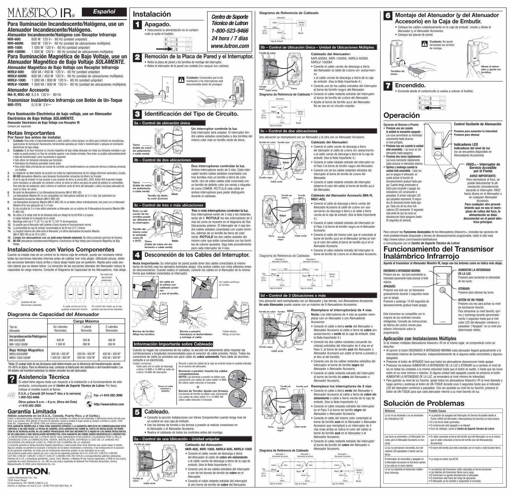
Instalación
ON
OF
F
ON
OF
F
ON
OF
F
11
Identificación del Tipo de Circuito.33
Remoción de la Placa de Pared y el Interruptor.• Retire la placa de pared y los tornillos de montaje del interruptor.• Retire el interruptor de la pared con cuidado (no saque los cables).
22
Un interruptor controla la luz.
Este interruptor será unipolar. El interruptor ten-drá cables aislados conectados a dos tornillos delmismo color más un tornillo verde de tierra.
Tierra
(Cable de cobre
sin aislamiento
o cable verde)
Desconexión de los Cables del Interruptor.4
Dos interruptores controlan la luz.
Ambos interruptores serán de 3 vías. Cada inter-ruptor tendrá cables aislados conectados contres tornillos más un tornillo a tierra de colorverde. Uno de estos cables está conectado conun tornillo de distinto color (no verde) o etiqueta-do como COMÚN. ROTULE este cable enambos interruptores para poder distinguirlodurante el cableado.
RótuloTornillo de distin-
to color (Común)
Tres o más interruptores controlan la luz.
Dos interruptores serán de 3 vías y los restantesserán de 4. ROTULE los dos interruptores de 3vías tal como se muestra en el diagrama de DosUbicaciones anterior. El interruptor de 4 vías ten-drá cables aislados conectados con cuatro tornil-los, además de un tornillo de tierra de colorverde. ROTULE los dos cables aislados delmismo color que están conectados con los tornil-los de colores opuestos. Siga este procedimientopara cada interruptor de 4 vías.
Rótulo
Nota: La ubi-
cación de los
tornillos puede
ser diferente en
su interruptor.
Tornillo del
mismo color
(o señalado
como IN
o OUT) Tierra
(Cable de cobre sin ais-
lamiento o cable verde)
Cuidado: Compruebe que la ali-mentación a los interruptores estédesconectada antes de proseguir.
Apagado.• Desconecte la alimentación en el cortacir-cuito (o quite el fusible).
5c – Control de dos ubicaciones
5d – Control de 3 Ubicaciones o más
ON
OF
F
ON
OF
F
ON
OF
F
Encendido.• Encienda desde el cortacircuito (o vuelva a colocar el fusible).
77
Operación
Lutron Electronics Co., Inc.7200 Suter RoadCoopersburg, PA 18036-1299 E.U.A.Hecho e impreso en los E.U.A. 12/06 P/N 030-864 Rev. B
Tipo deAtenuador
Incandescente/HalógenoMIR-600/600MMIR-1000/1000M
Bajo Voltaje MagnéticoMIRLV-600/600M*MIRLV-1000/1000M*
Sin LateralesRemovidos
600 W1 000 W
600 VA / 450 W*1 000 VA / 800 W*
1 LateralRemovido
500 W800 W
500 VA / 400 W*800 VA / 650 W*
2 LateralesRemovidos
400 W650 W
400 VA / 300 W*650 VA / 500 W*
Diagrama de Capacidad del Atenuador
A cada control se le haquitado la sección interior.
Al control del medio se le hanquitado las secciones laterales
No retire lasseccionesexteriores.
Montaje del Atenuador (y del AtenuadorAccesorio) en la Caja de Embutir.• Coloque los cables cuidadosamente en la caja de embutir, monte y alinee el
Atenuador (y el Atenuador Accesorio). • Coloque las placas de pared.
66
Tornillos de
inicio.
Cuidado: No ajustedemasiado los tornillosde montaje.
Solución de Problemas
3c – Control de tres o más ubicaciones
3b – Control de dos ubicaciones
3a – Control de ubicación única
Carga Máxima
Bornes de tornillo:
Afloje los tornillos.
Bornes a presión:
Introduzca el destornillador
y extraiga el cable.
Nota Importante: Su interruptor de pared puede tener dos cables conectados al mismoborne de tornillo (vea los ejemplos ilustrados abajo). Una ambos cables con cinta adhesiva antesde desconectarlos. Cuando realice el cableado, conecte los cables en el Atenuador de la mismaforma que estaban conectados al interruptor.
Un cable en
el orificio con
cableado poste-
rior
y uno al tornillo.
Un cable continuo al tornillo.
Cable atado:Afloje el tornillo.
Información Importante sobre Cableado
Cuando se hagan las conexiones de los cables, la sección sin aislamiento debe respetar lascombinaciones y longitudes recomendadas para el conector de cable provisto. Nota: Todos losconectores de cable ya provistos son para cable de cobre solamente. Para cable de aluminio,consulte a un electricista. Cable conector:
Úselo para unir el cable de descargaa tierra 14 AWG o 12 AWG al cable dea tierra 18 AWG del atenuador.
Trence el cableconector yajústelo.
Borneras a presión: Inserte los cables completamente.NOTA: Las borneras a presión se deben usarúnicamente con cables de cobre sólido 14 AWG.NO utilice cable retorcido ni trenzado.
Bornes de Tornillo: Ajuste con firmeza.Los bornes de tornillo se deben usar únicamentecon cables de cobre sólido 12 o 14 AWG. NOutilice cable retorcido ni trenzado.
Recorte o pele los cables de la caja de embutir hasta la medida indicadaen el reverso del atenuador.
O
Una ubicación se reemplazará con un Atenuador y la otra con un Atenuador Accesorio.
Tierra
Rótulo
Cable verde
Tornillo negro
Tornillo de cobre Tornillo azul
Tierra
Rótulo
Cable verdeTornillonegro
Tornillo decobre
Tornilloazul
Cableado del Atenuador:
• Conecte el cable verde de descarga a tierra del atenuador al cable de cobre sin aislamientoo al cable verde de descarga a tierra de la caja deembutir. (Vea la Nota Importante 4.)
• Conecte el cable rotulado extraído del interruptor enel Paso 3 al borne de tornillo negro del Atenuador.
• Conecte uno de los cables restantes extraídos delinterruptor al borne de tornillo de cobre delAtenuador.
• Conecte el cable restante extraído del interruptor(observe el color del cable) al borne de tornillo azuldel Atenuador.
Cableado del Atenuador Accesorio (MA-R,
MSC-AD):
• Conecte el cable de descarga a tierra verde delAtenuador Accesorio al cable de cobre sin ais-lamiento de descarga a tierra o al cable a tierraverde de la caja de embutir. (Vea la Nota Importante4.)
• Conecte el cable rotulado extraído del interruptor enel Paso 3 al borne de tornillo negro en el AtenuadorAccesorio.
• Conecte el cable del mismo color que el conectado alborne de tornillo azul en el Atenuador (arriba se indi-ca el color del cable) al borne de tornillo azul en elAtenuador Accesorio.
• Conecte el cable restante extraído del interruptor alborne de tornillo de cobre en el Atenuador Accesorio.
Atenuador
AtenuadorAccesorio
Azul
Vivo
120 V~60 Hz
Azul
Neutro
Apliquede luz
Cobre Cobre
NegroNegro
VerdeVerde
Tierra TierraCaja de embutir
Atenuador o Atenuador Accesorio
Atenuador o Atenuador Accesorio
Caja de embutir
Diagrama de Referencia de Cableado
Una ubicación será reemplazada con un Atenuador y las demás, con Atenuadores Accesorios.Un solo Atenuador puede usarse con un máximo de 9 Atenuadores Accesorios.
Reemplace el interruptor(es) de 4 vías
Nota: Los interruptores de 4 vías se pueden reem-plazar con un Atenuador o con AtenuadoresAccesorios• Conecte el cable a tierra verde del Atenuador o
Atenuador Accesorio al cable a tierra de cobre sinaislamiento o verde de la caja de embutir. (Veala Nota Importante 4.)
• Conecte los dos cables rotulados (recuerde loscolores) extraídos del interruptor de 4 vías en elPaso 3, al borne de tornillo azul del Atenuador oAtenuador Accesorio (un cable al borne a presión yel otro al del tornillo).
• Conecte uno de los cables restantes extraídos delinterruptor al borne de tornillo negro delAtenuador o Atenuador Accesorio.
• Conecte el cable restante extraído del interruptoral borne de tornillo de cobre del Atenuador oAtenuador Accesorio.
Tierra
Rótulo
Cable verde
Tornillo negro
Tornillo de cobre Tornilloazul
Atenuador oAtenuadorAccesorio
Reemplace los interruptores de 3 vías
• Conecte el cable a tierra verde del Atenuador oAtenuador Accesorio al cable a tierra de cobre sinaislamiento o cable a tierra verde de la caja deembutir. (Vea la Nota Importante 4.)
• Conecte el cable rotulado extraído del interruptoren el Paso 3 al borne de tornillo negro delAtenuador o Atenuador Accesorio.
• Conecte el cable del mismo color conectado alborne de tornillo azul en el Atenuador o AtenuadorAccesorio que reemplazó a un interruptor de 4vías (más arriba se indica el color del cable) alborne de tornillo azul en el Atenuador o elAtenuador Accesorio.
• Conecte el cable restante extraído del interruptoral borne de tornillo de cobre del Atenuador oAtenuador Accesorio.
Azul
Vivo
120 V~60 Hz
Azul
Neutro
Apliquede luz
Cobre Cobre
NegroNegro
VerdeVerde
Tierra TierraCaja de embutir
Atenuador o Atenuador Accesorio
Atenuador o Atenuador Accesorio
Atenuador o Atenuador Accesorio
Caja de embutir
AzulCobre
Negro
Verde
TierraCaja de embutir
Diagrama de Referencia de Cableado
Opciones de Botones a Presión• Presione una vez cuando
la unidad se encuentre apagada -Las luces aumentarán su intensidadsuavemente hasta alcanzar el nivel prefijado.
• Presione una vez cuando la unidadesté encendida - Las luces se iránatenuando hasta apagarse.
• Presione dos veces rápidamente -Las luces iluminarán rápidamentehasta alcanzar la intensidad máxima.
• Oprima y sostenga cuando launidad esté encendida - Cada vezque se apague el atenuador, sepuede activar la función dedesvanecimiento gradual hasta apa-gar. Cuando tenga presionado elbotón para encender y apagar, losindicadores LED comenzarán aparpadear. El primer indicador LEDque parpadea representa 10 segun-dos de desvanecimiento hasta apa-gar. Cada uno de los otros indi-cadores LED representa 10 segundosmás antes de que las luces sedesvanezcan hasta apagarse (hasta60 segundos de demora).
FASSTM – Interruptor deServicio Accesible
por el FrenteAVISO IMPORTANTE:
Para reemplazar el foco, sepuede desconectar la ali-mentación cómodamente
sacando el interruptor FASShacia afuera en el Atenuador o
en cualquier AtenuadorAccesorio.
Para cualquier otro proced-imiento que no sea el reem-plazo de rutina del foco, la
alimentación se debedesconectar en el panel eléc-
trico principal.
Para conocer las Funciones Avanzadas de los Atenuadores Maestro®, incluidas las opciones denivel predeterminado bloqueado y tiempo de desvanecimiento programable, visite el sitio webhttp://www.lutron.com/maestro/advfeatureso comuníquese con el Centro de Soporte Técnico de Lutron
Síntoma
La luz no se enciende o no se enciendenlos indicadores LED.
Las luces se encienden y el Atenuador fun-ciona, pero el Atenuador Accesorio no fun-ciona.
La luz no permanece encendida, los indi-cadores LED parpadean o tienen una luztenue.
El interruptor de encendido y apagado enel Atenuador Accesorio no funciona cuandola luz está en el nivel máximo.La luz no responde al transmisor inalám-brico infrarrojo.
Posible Causa
• La posición de apagado del Interruptor de Servicio Accesible desde elFrente (FASS) del Atenuador o Atenuador(es) Accesorio(s) es hacia afuera.
• El o los focos están quemados.• El cortacircuito está apagado o se disparó.• Error de cableado. Llame al Centro de Soporte Técnico de Lutron
• El cable conectado al borne del tornillo azul del Atenuador no es el mismoque el cable conectado al borne del tornillo azul del Atenuador(es)Accesorio(s).
• El borne del tornillo azul está conectado con el neutro o está tocando tierra.
• La carga es menor que 60 W.
• Las baterías del transmisor están colocadas en forma incorrecta.• Las baterías del transmisor tienen poca carga.• El transmisor no apunta directamente al atenuador.• El transmisor está fuera del rango de operación.• El Atenuador ya ha recibido y respondido al comando.
Alinee el atenu-
ador y ajuste los
tornillos.
IR®
Para Iluminación Incandescente/Halógena, use unAtenuador Incandescente/Halógeno.Atenuador Incandescente/Halógeno con Receptor InfrarrojoMIR-600: 600 W 120 V~ 60 Hz (unidad unipolar)MIR-600M: 600 W 120 V~ 60 Hz (unidad de ubicaciones múltiples)MIR-1000: 1 000 W 120 V~ 60 Hz (unidad unipolar)MIR-1000M: 1 000 W 120 V~ 60 Hz (unidad de ubicaciones múltiples)
Para Iluminación Magnética de Bajo Voltaje, use unAtenuador Magnético de Bajo Voltaje SOLAMENTE.Atenuador Magnético de Bajo Voltaje con Receptor InfrarrojoMIRLV-600: 600 VA / 450 W 120 V~ 60 Hz (unidad unipolar)MIRLV-600M: 600 VA / 450 W 120 V~ 60 Hz (unidad de ubicaciones múltiples)MIRLV-1000: 1 000 VA / 800 W 120 V~ 60 Hz (unidad unipolar)MIRLV-1000M: 1 000 VA / 800 W 120 V~ 60 Hz (unidad de ubicaciones múltiples)
Atenuador AccesorioMA-R, MSC-AD 8,3 A 120 V~ 60 Hz
Transmisor Inalámbrico Infrarrojo con Botón de Un-ToqueMIR-ITFS 0,15 W 3 V
Para Iluminación Electrónica de bajo voltaje, use un AtenuadorElectrónico de Bajo Voltaje SOLAMENTE.Atenuador Electrónico de Bajo Voltaje con Receptor IRCompre por separado
Funcionamiento del TransmisorInalámbrico Infrarrojo
Aplicación con Instalaciones MúltiplesSi se instalan múltiples Atenuadores Maestro IR en el mismo lugar, se comportarán como sedescribe:• Al oprimir el botón ENCENDIDO A INTENSIDAD MÁXIMA cada atenuador llegará gradualmente a la
intensidad máxima de iluminación, independientemente de si algunos están encendidos y algunosapagados.
• Presionar el botón de APAGADO hará que todos los atenuadores desvanezcan hasta apagar.• Presionar los botones AUMENTAR LA INTENSIDAD DE LA LUZ o ATENUAR va a cambiar el nivel de
luz en todas las unidades a la misma velocidad hasta que el botón se suelte, o hasta que las lucesestén en su nivel mínimo o máximo. Si alguna unidad está apagada cuando se presiona el botónAUMENTAR LA INTENSIDAD DE LA LUZ, se encenderá al nivel mínimo de intensidad.
• Para guardar su nivel de luz favorito, ajuste todos los atenuadores Maestro IR al nivel deseado yluego oprima y sostenga el botón de UN-TOQUE durante unos 3 segundos hasta que el indicadorLED del atenuador comience a parpadear. Una vez ajustado su nivel de luz favorito, presione elbotón de UN-TOQUE para que cada atenuador retorne a su nivel favorito de luz.
Apunte el transmisor al Atenuador Maestro IR, luego use los botones como se indica más abajo.
ENCENDIDO A INTENSIDAD MÁXIMA:Presione una vez - las luces aumentarán suintensidad suavemente hasta alcanzar el brillomáximo.APAGADO:Presione una sola vez: se desvanecegradualmente durante 3 segundos hastaque se apaga.Presione y sostenga: 10-60 segundos dedesvanecimiento gradual hasta apagar.
Este transmisor es compatible con lamayoría de los controles remotosinteligentes. Consulte las instruccionesde fábrica del control remoto paraobtener información sobre laprogramación.
AUMENTAR LA INTENSIDADDE LA LUZ:Presione para aumentar la intensidadde las luces:
ATENUAR:Presione para atenuar las luces.
BOTÓN DE UN-TOQUE:Presione una vez para activar su nivelde iluminación favorito.Para almacenar su nivel favorito, opri-ma y mantenga durante aproximada-mente 3 segundos hasta que el indi-cador LED del atenuador comience aparpadear. (“Apagado” es un nivel pre-determinado válido).
Cableado.• Consulte la sección Instalaciones con Varios Componentes cuando tenga más de
un control en una caja de embutir.• Use los bornes de tornillo o los bornes a presión al realizar conexiones en
el Atenuador o el Atenuador Accesorio.• Realice el cableado de todos los controles antes del montaje.
5
Tierra
(Cable de cobre
sin aislamiento
o cable verde)
Cableado del Atenuador:
MIR-600, MIR-1000, MIRLV-600, MIRLV-1000
• Conecte el cable verde de descarga a tierra del Atenuador al cable de cobre sin aislamientoo al cable verde de descarga a tierra de la caja deembutir. (Vea la Nota Importante 4.)
• Conecte uno de los cables extraídos del interruptor a uno de los bornes de tornillo de cobre en elAtenuador.
• Conecte el cable restante extraído del interruptor al otro borne de tornillo de cobre del Atenuador.
Tierra
Cable verde
Tornillo decobre
Tornillo de cobre
5a – Control de una Ubicación – Unidad unipolar
Cableado del Atenuador:
MIR-600M, MIR-1000M, MIRLV-600M,MIRLV-1000M• Conecte el cable verde de descarga a tierra
del Atenuador al cable de cobre sin aislamien-too al cable verde de descarga a tierra de la cajade embutir. (Vea la Nota Importante 4.)
• Conecte uno de los cables extraídos del interruptoral borne de tornillo negro del Atenuador.
• Conecte el cable restante extraído del interruptor al borne de tornillo de cobre del Atenuador.
• Ajuste el borne de tornillo azul del Atenuador. No se usa en un circuito unipolar.
Diagrama de Referencia de Cableado
5b – Control de Ubicación Única – Unidad de Ubicaciones Múltiples
Azul
Vivo
120 V~60 Hz
Neutro
Apliquede luz
Cobre
Negro
Verde
TierraCaja de embutir
Atenuador
TierraCable verde
Tornillonegro
Tornillo de cobre
Atenuador
Diagrama de Referencia de Cableado
Vivo
120 V~60 Hz Neutro
Apliquede luz
Cobre
Cobre
Verde
Tierra
Caja de embutir
Atenuador
Atenuador
Tierra
Rótulo
Cable verdeTornillonegro
Tornillo decobre
Tornillo azul
Atenuador oAtenuadorAccesorio
Centro de SoporteTécnico de Lutron1-800-523-946624 hora / 7 díaswww.lutron.com
Control Oscilante de Atenuación
Presione para aumentar la intensidadPresione para atenuar
Indicadores LEDIndicadores del nivel de luz(no se encuentra disponible enAtenuadores Accesorios)
*Nota: El wataje total de las lámparas está determinado por la eficiencia del transformador, siendo70–85% lo típico. Para la eficiencia real, contacte al fabricante del artefacto o del transformador. LosVA totales del transformador(es) no deben exceder los del atenuador.